WO2021182213A1 - Tip saw and method for manufacturing same - Google Patents
Tip saw and method for manufacturing same Download PDFInfo
- Publication number
- WO2021182213A1 WO2021182213A1 PCT/JP2021/008089 JP2021008089W WO2021182213A1 WO 2021182213 A1 WO2021182213 A1 WO 2021182213A1 JP 2021008089 W JP2021008089 W JP 2021008089W WO 2021182213 A1 WO2021182213 A1 WO 2021182213A1
- Authority
- WO
- WIPO (PCT)
- Prior art keywords
- pitch
- tip
- cutting
- base metal
- tip saw
- Prior art date
Links
Images


Classifications
-
- B—PERFORMING OPERATIONS; TRANSPORTING
- B23—MACHINE TOOLS; METAL-WORKING NOT OTHERWISE PROVIDED FOR
- B23D—PLANING; SLOTTING; SHEARING; BROACHING; SAWING; FILING; SCRAPING; LIKE OPERATIONS FOR WORKING METAL BY REMOVING MATERIAL, NOT OTHERWISE PROVIDED FOR
- B23D47/00—Sawing machines or sawing devices working with circular saw blades, characterised only by constructional features of particular parts
-
- B—PERFORMING OPERATIONS; TRANSPORTING
- B23—MACHINE TOOLS; METAL-WORKING NOT OTHERWISE PROVIDED FOR
- B23D—PLANING; SLOTTING; SHEARING; BROACHING; SAWING; FILING; SCRAPING; LIKE OPERATIONS FOR WORKING METAL BY REMOVING MATERIAL, NOT OTHERWISE PROVIDED FOR
- B23D61/00—Tools for sawing machines or sawing devices; Clamping devices for these tools
- B23D61/02—Circular saw blades
-
- B—PERFORMING OPERATIONS; TRANSPORTING
- B27—WORKING OR PRESERVING WOOD OR SIMILAR MATERIAL; NAILING OR STAPLING MACHINES IN GENERAL
- B27B—SAWS FOR WOOD OR SIMILAR MATERIAL; COMPONENTS OR ACCESSORIES THEREFOR
- B27B33/00—Sawing tools for saw mills, sawing machines, or sawing devices
- B27B33/02—Structural design of saw blades or saw teeth
- B27B33/08—Circular saw blades
-
- B—PERFORMING OPERATIONS; TRANSPORTING
- B28—WORKING CEMENT, CLAY, OR STONE
- B28D—WORKING STONE OR STONE-LIKE MATERIALS
- B28D1/00—Working stone or stone-like materials, e.g. brick, concrete or glass, not provided for elsewhere; Machines, devices, tools therefor
- B28D1/02—Working stone or stone-like materials, e.g. brick, concrete or glass, not provided for elsewhere; Machines, devices, tools therefor by sawing
- B28D1/04—Working stone or stone-like materials, e.g. brick, concrete or glass, not provided for elsewhere; Machines, devices, tools therefor by sawing with circular or cylindrical saw-blades or saw-discs
Definitions
- One form of the present disclosure relates to a tipped saw and a method for manufacturing a tipped saw.
- the tipped saw cuts, for example, wood and wood materials, ceramic materials such as outer walls, steel materials such as pipes, and work materials of non-ferrous metal materials such as aluminum.
- the tip saw has a disk-shaped base metal and a plurality of cutting chips joined to the outer circumference of the base metal.
- the cutting tip is composed of, for example, a cemented carbide or a polycrystalline diamond (PCD) sintered body.
- the cutting tips are arranged at predetermined intervals (pitch) in the circumferential direction of the base metal.
- the cutting tip is joined to the base metal in a posture in which the rake face faces in the circumferential direction of the base metal.
- the cutting edge at the edge of the rake face of the cutting tip cuts the work material.
- a plurality of cutting tips intermittently cut the work material to form a groove in the work material. As a result, the work material can be cut with a tip saw.
- Each cutting tip receives cutting resistance from the work material when cutting the work material.
- the component of the cutting resistance in the thickness direction (lateral direction) of the base metal vibrates the tip saw in the lateral direction to generate cutting vibration.
- the exciting force is generated intermittently each time the cutting tips arranged at intervals cut the work material.
- the intermittent frequency (Hz) of the exciting force generated each time each cutting tip cuts the work material is obtained by the following formula (1).
- Intermittent frequency (Hz) ⁇ 360 x rotation speed (rpm) ⁇ / ⁇ 60 x pitch (°) ⁇
- the excitation frequency that causes the cutting vibration is often an intermittent frequency, a harmonic frequency that is an integral multiple of the intermittent frequency, or a low harmonic frequency that is an integral fraction of the intermittent frequency.
- a large cutting vibration is generated in the tip saw due to the resonance phenomenon.
- the cutting vibration of the tip saw increases, the cutting power and cutting noise increase. Further, since defects such as pattern skipping are likely to occur in the work material, the cutting quality of the work material may deteriorate.
- Japanese Patent No. 3030705 and Japanese Patent No. 6472875 disclose random pitch tipped saws.
- the size of each pitch varies. Therefore, there are variations in each intermittent frequency corresponding to each cutting tip. As a result, the vibration frequency is dispersed, and the vibration force due to the vibration frequency that matches the natural frequency of the tip saw can be suppressed.
- the excitation force due to the excitation frequency tends to be concentrated in a narrow frequency region centered on the intermittent frequency. Therefore, when the peak of the excitation frequency and the natural frequency of the tip saw match, the amplitude of the cutting vibration may increase. Therefore, we propose a tip saw that can effectively suppress cutting vibration.
- the tipped saw is used at the time of cutting.
- the tip saw has a disk-shaped base metal and a plurality of cutting tips joined to the outer periphery of the base metal.
- a circumferential pitch is formed between the plurality of cutting tips.
- the pitch includes the maximum pitch and the minimum pitch, and the ratio of the magnitude of the maximum pitch to the magnitude of the minimum pitch is three times or more.
- the intermittent frequency is inversely proportional to the pitch of the cutting tip. Therefore, the ratio of the maximum value and the minimum value of the intermittent frequency is also tripled or more. As a result, the excitation frequency is dispersed in a wide frequency domain. Therefore, the exciting force due to the exciting frequency that matches the natural frequency of the tip saw can be reduced. Thus, the cutting vibration of the tip saw can be effectively suppressed.
- the arrangement of the plurality of cutting tips is rotationally asymmetric with respect to the rotation axis passing through the disk-shaped center of the base metal.
- the rotational asymmetry indicates a property that the same shape cannot be obtained unless it is rotated by 360 ° when rotating about the rotation axis. Therefore, the aperiodicity of the intermittent frequency becomes large. Therefore, it is easier to disperse the excitation frequency. As a result, the excitation force due to the excitation frequency can be further dispersed and reduced.
- the plurality of cutting tips include a first tip and a second tip constituting a pitch.
- the first chip and the second chip are joined to the first blade and the second blade, respectively, which protrude outward in the radial direction from the main body of the base metal.
- a dummy blade that protrudes outward in the radial direction from the main body of the base metal and to which the cutting tip is not joined is provided. Insertion recesses are formed between the dummy blade and the first blade, and between the dummy blade and the second blade, into which a feed rod used for polishing the cutting tip is inserted.
- the cutting tip is polished, for example, by bringing a rotating grindstone close to the polishing position.
- the plurality of cutting tips are sequentially sent to the polishing position by rotating the base metal at a predetermined angle.
- the feed rod is inserted into the insertion recess of the base metal and moved along the circumferential direction of the base metal.
- the base metal rotates by a predetermined angle. Therefore, by providing the insertion recesses between the predetermined pitches, the base metal can be rotated by the feed rod at an angle smaller than the maximum value of the pitch. As a result, the cutting tip can be polished smoothly and efficiently.
- the tip saw has a disk-shaped base metal and a plurality of cutting tips joined to the outer periphery of the base metal.
- a circumferential pitch is formed between the plurality of cutting tips. Includes first pitch, second pitch and third pitch in which the pitch ratio is relatively prime.
- the intermittent frequency is inversely proportional to the pitch of the cutting tip. Therefore, each intermittent frequency is dispersed by pitches of at least three magnitudes. Moreover, the ratio of each intermittent frequency is relatively prime. When harmonics of different intermittent frequencies overlap, it is a case where the frequencies are common multiples of each other.
- the common multiple of intermittent frequencies, which are relatively prime, is a very large frequency. Since cutting vibration at a large frequency is unlikely to occur, cutting vibration of the tip saw can be suppressed.
- the tip saw has a plurality of tip sets composed of a plurality of adjacent cutting tips arranged at a pitch including the first pitch, the second pitch, and the third pitch. Therefore, each intermittent frequency is dispersed by a combination of pitches of at least three magnitudes that are relatively prime. Further, the tip saw is easily formed by repeatedly holding the tip set. Further, in a tip saw having many cutting tips, if all pitches are set in a relatively prime relationship, the difference between the pitches tends to be small. Therefore, by allowing the chip set to be repeated, the difference between the pitches, which are relatively prime, can be made larger than a predetermined value. As a result, the exciting force due to the exciting frequency that matches the natural frequency of the tip saw can be reduced.
- the difference in size between the first pitch, the second pitch, and the third pitch is (10 / number of cutting chips) ° or more. Therefore, it is possible to provide a difference of a predetermined value or more in the magnitude of each intermittent frequency. Therefore, it is possible to prevent the intermittent frequencies from approaching each other. As a result, the exciting force due to the exciting frequency that matches the natural frequency of the tip saw can be reduced.
- Each pitch is determined so that the ratio of each pitch in the circumferential direction between the plurality of cutting tips connected to the disk-shaped base metal includes at least three relatively prime integers.
- a plurality of cutting tips are joined to the outer circumference of the base metal at each pitch.
- the intermittent frequency is inversely proportional to the pitch of the cutting tip. Therefore, each intermittent frequency is dispersed by pitches of at least three magnitudes.
- the ratio of each intermittent frequency is relatively prime. When harmonics of different intermittent frequencies overlap, it is a case where the frequencies are common multiples of each other.
- the common multiple of intermittent frequencies, which are relatively prime is a very large frequency. Since cutting vibration at a large frequency is unlikely to occur, cutting vibration of the tip saw can be suppressed.
- the tip saw 1 has a disk-shaped base metal 2 and a plurality of cutting tips 10 joined to the outer periphery of the base metal 2.
- the tip saw 1 is not a structure in which a plurality of base metal 2s are joined, for example, but is used alone at the time of cutting.
- the tip saw 1 is rotatably attached to a cutting tool such as a rechargeable battery type electric circular saw or a stationary type tip saw cutting machine. The tip saw 1 rotates the base metal 2 to form a groove in the work material with each cutting tip 10, and finally cuts the work material.
- the work material is, for example, wood and wood-based materials, resin-based materials, composite materials, or ceramic-based materials such as siding boards.
- the work material is a steel material such as carbon steel, general structural rolled steel, chrome molybdenum steel, stainless steel, cast iron, or a non-ferrous metal such as aluminum and aluminum alloy, copper and copper alloy.
- a substantially circular mounting hole 3 penetrating in the plate thickness direction of the base metal 2 is provided at the center of the base metal 2.
- the rotating shaft of the cutting tool is inserted into the mounting hole 3, and the tip saw 1 is mounted on the cutting tool.
- the tip saw 1 rotates clockwise in FIG. 1 with the center 2a of the base metal 2 as the center.
- a plurality of projecting portions 4 and 7 projecting outward in the radial direction of the base metal 2 are provided on the peripheral edge of the base metal 2 at predetermined intervals.
- the protruding portion 4 has a tip sheet 6 notched in a rectangular shape at the front end portion of the tip saw 1 in the rotation direction.
- the cutting tip 10 is joined to the tip sheet 6.
- the protrusion (dummy blade) 7 is provided between the protrusion (first blade) 4a and the protrusion (second blade) 4b.
- a cutting tip (first tip) 10d and a cutting tip (second tip) 10e are joined to the first blade 4a and the second blade 4b, respectively.
- the dummy blade body 7 projects outward in the radial direction of the base metal 2 without having the chip sheet 6. Therefore, the cutting tip 10 is not joined to the dummy blade body 7.
- a tooth chamber (insertion recess) 5 recessed in the circumferential direction is formed between the protrusions 4 and 7.
- the tooth chamber 5 is provided between the adjacent protrusions 4, between the adjacent first blade 4a and the dummy blade 7, or between the adjacent second blade 4b and the dummy blade 7.
- the tooth chambers 5 are provided at intervals of predetermined angles in the circumferential direction of the base metal 2.
- a plurality of external slits 8 extending inward in the radial direction of the base metal 2 from the tooth chamber 5 are provided on the disk surface of the base metal 2.
- the external slit 8 may not be provided.
- An internal slit may be provided in addition to or in place of the external slit 8. Both ends of the internal slit are located in the central region of the base metal 2, and are not open to, for example, the tooth chamber 5.
- the cutting tip 10 has a rake face 10a in front of the tip saw 1 in the rotation direction.
- the cutting tip 10 has a flank surface 10b outward in the radial direction of the base metal 2.
- the cutting edge 10c is formed at the intersection of the rake face 10a and the flank surface 10b.
- Each cutting edge 10c is set to the same height in the radial direction.
- Each cutting tip 10 is arranged with a pitch 11 in the circumferential direction.
- the pitch 11 is an angle in the circumferential direction about the center 2a (see FIG. 1) of the base metal 2.
- the pitch 11 is an angle between adjacent virtual lines, for example, assuming a virtual line passing through the center 2a and the cutting edge 10c of each cutting tip 10.
- the outer diameter of the tip saw 1 is, for example, 50 to 200 mm. In the tip saw 1 having an outer diameter of 125 mm, 1 ° of the pitch corresponds to a length of 1.09 mm in the circumferential direction.
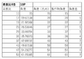
- the tip saw 1 has 10 pitches 11a to 11j between each of the 10 cutting tips 10.
- the pitches 11a to 11j are set, for example, at the manufacturing angle shown in FIG.
- the pitches 11a to 11j have a ratio of 13:53:17:47: 19: 43: 23: 37: 29: 31 in order from the pitch 11a toward the front in the rotation direction of the tip saw 1. That is, the pitches 11a to 11j are relatively prime to each other.
- the ratio (pitch ratio) between the maximum pitch 11b and the minimum pitch 11a is 53:13, which is approximately 4 times, for example, 3 to 5 times.
- the minimum value of the difference between the pitches 11a to 11j is 2 °.
- the pitches shown in FIGS. 3, 5 to 11 are arranged in the order of their sizes, and do not indicate the order of arrangement in the circumferential direction.
- the tip saw 1 has three or more cutting tips 10 arranged in the circumferential direction of the base metal 2 and a tip group 12 having three or more different pitches 11.
- the chip group 12 is composed of, for example, pitches 11a, 11b, 11c and three cutting chips 10 located at the rear end or the front end of each pitch 11a, 11b, 11c in the rotation direction.
- the pitches 11a, 11b, 11c of the chip group 12 and the three cutting chips 10 are alternately arranged in the circumferential direction of the base metal 2. Since the sizes of the pitches 11a to 11j are all different, the tip saw 1 has a shape that does not have the tip group 12 repeatedly.
- the chip group 12 may be composed of, for example, another three pitches alternately arranged in the circumferential direction of the base metal 2 and the other three cutting chips 10.
- the chip group 12 may be composed of four or more pitches and the same number of cutting chips 10 as the pitches.
- the ratios of pitches 11a to 11j are set in a relatively prime relationship.
- the angle (°) obtained by allocating 360 ° of the entire circumference of the base metal 2 at each ratio of pitches 11a to 11j is obtained.
- the total of the rounded angles is 360 °
- the rounded angles are set as the manufacturing angles. If the sum of the rounded angles is greater than 360 °, one or more pitches 11 are rounded down by 1 ° to a sum of 360 °.
- the sum of the rounded angles is less than 360 °, one or more pitches 11 are rounded up by 1 ° to a sum of 360 °.
- the total of the rounded angles is 361 °. Therefore, the pitch of 33 ° is devalued by 1 ° and 32 ° is set as the manufacturing angle. As a result, the total of the pitches 11a to 11j becomes 360 °.
- the rounding process is performed so that it becomes an integer, the digit may be changed and the rounding process may be performed after the decimal point.
- a protrusion 4 is provided on the outer periphery of the base metal 2 based on the size of each pitch 11.
- a chip sheet 6 is provided at the front end of each protrusion 4 in the rotation direction.
- the cutting tip 10 is joined to each tip sheet 6.
- a dummy blade body 7 projecting outward in the radial direction is formed between the adjacent projecting portions 4.
- a dummy blade 7 is formed between the first blade 4a and the second blade 4b at both ends of the pitch 11b, which is the maximum value.
- the tooth chamber 5 is formed between the first blade body 4a and the dummy blade body 7, and between the second blade body 4b and the dummy blade body 7.
- the maximum amplitude of the tip saw 1 can be suppressed by more than half as compared with the conventional case by setting the pitch ratio to 3 times or more.
- the pitch ratio is excessive, the maximum amplitude can be suppressed more, but the excessive pitch ratio may have an adverse effect.
- one pitch is larger than the other pitch.
- the insert after a large pitch cuts the work material with a large thickness. In this case, a large cutting resistance is applied to the chip as compared with other chips. Therefore, it is considered that the pitch ratio capable of effectively suppressing the maximum amplitude is 3 times or more, more preferably 5 times or less.
- FIG. 5 shows Experimental Example 1 of pitches 11a to 11j (see FIG. 1).
- the pitches 11a to 11j of Experimental Example 1 are relatively prime to each other.
- the pitch ratio is 127:43, which is approximately three times.
- the angle (°) obtained by rounding off the second decimal place of the angle (°) in which 360 ° of the entire circumference of the base metal 2 is allocated at each ratio is obtained. Since the total of the rounded angles is 360.2 °, the pitches of 29.1 ° and 34.3 ° are rounded down by 0.1 ° and set to 29 ° and 34.2 °, respectively.
- the minimum value of the difference between the pitches 11a to 11j is 2.6 °.
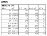
- FIG. 6 shows Experimental Example 2 with pitches 11a to 11j (see FIG. 1).
- the pitches 11a to 11j of Experimental Example 2 are relatively prime to each other.
- the pitch ratio is 131: 73, which is approximately 1.8 times.
- the angle (°) obtained by rounding off the second decimal place of the angle (°) in which 360 ° of the entire circumference of the base metal 2 is allocated at each ratio is obtained. Since the total of the rounded angles is 360 °, the rounded angles are set as the manufacturing angles.
- the minimum value of the difference between the pitches 11a to 11j is 1.4 °, which is smaller than the experimental examples shown in FIGS. 3 and 5.
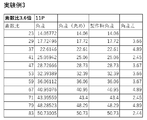
- FIGS. 7 to 11 show experimental examples 3 to 7 of pitch 11 (see FIG. 1), respectively.
- the tip saws of Experimental Examples 3 to 7 have 11 cutting tips 10 and 11 pitches 11.
- the pitch 11 is relatively prime to all blades.
- the angle (°) obtained by rounding off the third decimal place of the angle (°) in which 360 ° of the entire circumference of the base metal 2 is allocated at each ratio is obtained.
- the rounded angles are set as the manufacturing angles.
- the total of the rounded angles is larger than 360 ° as in Experimental Example 6, one or more pitches 11 are rounded down by 0.01 ° to make the total 360 °.
- the pitch 11 of Experimental Example 3 has a pitch ratio of 83:23, which is approximately 3.6 times.
- the minimum value of the difference between the pitches 11 is 2.44 °.
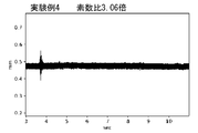
- the pitch 11 of Experimental Example 4 has a pitch ratio of 89:29, which is approximately 3.06 times.
- the minimum value of the difference between the pitches 11 is 2.19 °.
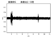
- the pitch 11 of Experimental Example 5 has a pitch ratio of 113:53, which is approximately 2.13 times.
- the minimum value of the difference between the pitches 11 is 1.56 °.
- the pitch 11 of Experimental Example 6 has a pitch ratio of 197: 127, which is approximately 1.55 times.
- the minimum value of the difference between the pitches 11 is 0.81 °. As shown in FIG. 11, the pitch 11 of Experimental Example 7 has a pitch ratio of 457: 383, which is approximately 1.19 times. The minimum value of the difference between the pitches 11 is 0.31 °. As described above, as the pitch ratio becomes smaller, the minimum value of the difference between the pitches 11 tends to become smaller.
- the cutting vibration when cutting the work material was measured for the random pitch tip saws of Experimental Examples 3 to 7.
- the amplitude of the cutting vibration tends to be suppressed as the pitch ratio increases.
- the amplitude of cutting vibration was suppressed to be small.
- the cutting vibration of the tip saw of Experimental Example 4 shown in FIG. 13 has an amplitude of approximately 10 to 30% of the cutting vibration of the tip saw of Experimental Example 7 shown in FIG.
- the cutting vibration during cutting was substantially constant except at the start of cutting.
- FIG. 18 shows the relationship between the intermittent frequency and the exciting force of each tip saw having a different pitch.
- the equipitch tip saw shown in FIG. 18 has a plurality of cutting tips 10 arranged at a pitch 41 of the same size as schematically shown in FIG.
- the random pitch tip saw shown in FIG. 18 has a pitch 42 having a ratio of 1: 2 and a plurality of cutting tips 10 alternately arranged in the circumferential direction at a pitch 43 as schematically shown in FIG.
- the randomly pitched tip saws shown in FIG. 18 have a plurality of cutting tips 10 arranged at pitches 11a to 11c and 11h to 11j having sizes relatively prime to each other as schematically shown in FIG. Has.
- the random pitch which is relatively prime for all blades, has a relatively prime relationship no matter which two pitches are selected.
- Each of the three types of tip saws has 10 cutting tips 10 (see FIG. 1) and is used at a rotation speed of 6000 rpm.
- the intermittent frequency of each tip saw shown in FIG. 18 has an inverse proportional relationship with each pitch (°) as referred to the equation (1).
- the equipitch tip saw is concentrated in a narrow frequency region centered on 1000 Hz and has a large excitation force at intermittent frequencies.
- the intermittent frequencies of a random pitch tip saw with a ratio of 1: 2 have peaks in each of the two narrow frequency regions, centered on the 2: 1 ratio of 1000 Hz and 500 Hz.
- the first peak centered at 1000 Hz is, for example, approximately three-quarters of the maximum exciting force of a tipped saw having an equal pitch.
- the first peak centered at 500 Hz is, for example, approximately half of the maximum exciting force of a tipped saw having an equal pitch.
- Each intermittent frequency corresponding to the random pitch of all blades relatively prime is dispersed in a wide frequency range. For example, it is dispersed with a relatively wide width of 250 Hz in the front and rear around 1000 Hz. As a result, the maximum excitation force of the intermittent frequency is suppressed to, for example, one-fourth or less of the maximum excitation force of the tip saw having an equal pitch.
- the peak of each intermittent frequency seen at 100 Hz on the left side in FIG. 18 corresponds to the rotation speed of the tip saw of 6000 rpm.
- the intermittent frequency of each tip saw shown in FIG. 18 has a proportional relationship with the rotation speed of the tip saw as referred to the equation (1). Therefore, when the rotation speed of the tip saw is increased, the peak of the intermittent frequency moves to a high frequency region.
- the natural frequency of the tip saw also correlates with the rotation speed of the tip saw. For example, by increasing the rotation speed of the tip saw, the natural frequency of the tip saw moves to a high frequency region.
- the intermittent frequency the amount of movement due to the change in the rotation speed of the tip saw is larger than the natural frequency of the tip saw. Therefore, when changing the rotation speed of the tip saw, the intermittent frequency and the natural frequency of the tip saw may match.
- the cutting vibration increases corresponding to the exciting force of the intermittent frequency that matches the natural frequency of the tip saw. Therefore, in a random pitch tip saw in which all blades are relatively prime, the frequency range in which the intermittent frequency and the natural frequency of the tip saw can match is wide. On the other hand, the exciting force of the intermittent frequency that matches the natural frequency of the tip saw can be suppressed to, for example, one-fourth or less of that of a tip saw having an equal pitch. As a result, cutting vibration can be suppressed to a small extent.
- the cutting vibration of the tipped saw having an equal pitch was measured under the same conditions as in Experimental Examples 3 to 7 shown in FIGS. 12 to 16.
- the cutting vibration of the tipped saw of equal pitch tends to have a larger amplitude than that of the tipped saw of Experimental Example 6 shown in FIG. 15, and tends to be suppressed more than that of the tipped saw of Experimental Example 7 shown in FIG. It is considered that this is because the amount of coincidence between the intermittent frequency concentrated in the narrow frequency region of the tipped saw having an equal pitch and the natural frequency of the tipped saw was small.
- the peak of the exciting force at the intermittent frequency and the natural frequency of the tip saw can easily match. Therefore, the amplitude of the cutting vibration of the tipped saw having an equal pitch can be easily increased depending on the rotation speed of the tipped saw, as compared with the tipped saw of Experimental Example 7, for example.
- the base metal 2 is created in step 01 shown in FIG. 21 (hereinafter, abbreviated as ST) 01.
- the base metal 2 is formed with a protruding portion 4 having a chip sheet 6 and a dummy blade body 7 not provided with the chip sheet 6.
- the cutting tip 10 is joined to the tip sheet 6 of the base metal 2 (ST02 in FIG. 21).
- the base metal 2 is set in the polishing apparatus so that the base metal 2 rotates around the center 2a (see FIG. 1) (ST03).
- the cutting tips 10 of the tip saw 1 set in the polishing device are sequentially polished (ST04).
- the feed rod 30 enters the tooth chamber 5 from the side of the base metal 2 (ST05).
- the feed rod 30 is moved in the direction opposite to the rotation direction of the tip saw 1 (downward in FIG. 20) by a predetermined distance.
- the tip saw 1 rotates about a center 2a (see FIG. 1) by a predetermined angle.
- the feed rod 30 feeds the cutting tip 10 to the polishing position (ST06).
- the feed rod 30 separates from the tooth chamber 5 in the thickness direction of the base metal 2 (ST07). Therefore, the feed rod 30 moves to the initial position (ST08).
- the grindstone 31 is rotated to bring it closer to the cutting tip 10 at the polishing position. As a result, the grindstone 31 polishes the cutting tip 10 (ST09). The grindstone 31 polishes the rake face 10a and / or the flank surface 10b of the cutting tip 10.
- the feed rod 30 enters the tooth chamber 5 in front of the cutting tip 10 for which the polishing work has been completed (ST05). The feed rod 30 feeds each cutting tip 10 to the polishing position in order. As a result, the polishing process is performed until the polishing of all the cutting tips 10 is completed.
- the polishing process of the cutting tip 10 is completed (ST10), the production of the tip saw 1 is completed.
- the pitch ratio between the maximum value and the minimum value is, for example, four times. Therefore, when the base metal 2 is to be rotated by the feed rod 30 (see FIG. 21) according to each pitch 11, it is necessary to change the rotation angle of the base metal 2 for each polishing process.
- the tooth chambers 5 are provided at intervals of a predetermined angle in the circumferential direction of the base metal 2.
- the feed rod 30 is moved from the outside in the axial direction into the outer space of each of the tooth chambers 5 or the protrusions 4 and 7 where there is no cutting tip. Subsequently, the feed rod 30 is rotated by a predetermined amount (for example, at intervals of the same angle) in the circumferential direction.
- the feed rod 30 that has entered the tooth chamber 5 or the space hits the wall surface or the tip of the tooth chamber 5 and pushes the tip saw 1 in the circumferential direction.
- the base metal 2 can be rotated, and all the cutting tips 10 can be polished.
- the feed rod 30 is rotated in the circumferential direction at regular intervals of 36 ° or more and less than 40 °.
- the feed rod 30 is retracted outward in the axial direction, and the feed rod 30 is moved in the circumferential direction to return to the original position. Subsequently, the feed rod 30 is re-entered from the outside in the axial direction into the outer space of each of the tooth chambers 5 or the protrusions 4 and 7 where there is no cutting tip. Then, the feed rod 30 is rotated in the circumferential direction. By repeating these operations, the tip saw 1 can be rotated, and all the cutting tips 10 can be polished.
- the feed rod 30 is made to enter the tooth chamber 5 in front of the dummy blade 7 in the rotation direction without performing ST09 (see FIG. 21) (see FIG. 21).
- ST05 the grindstone 31 is rotated (idle) in front of the dummy blade 7 in the same manner as in the case of polishing the cutting tip 10.
- the polishing process of the cutting tip 10 can be smoothly performed.
- the tip saw 1 is used at the time of cutting.
- the tip saw 1 has a disk-shaped base metal 2 and a plurality of cutting tips 10 joined to the outer periphery of the base metal 2.
- the pitch 11 of the plurality of cutting tips 10 has a plurality of different sizes.
- the ratio of the maximum pitch 11b to the minimum pitch 11a is three times or more.
- the intermittent frequency is inversely proportional to the pitch 11 of the cutting tip 10. Therefore, the ratio of the maximum value and the minimum value of the intermittent frequency is also tripled or more. As a result, the excitation frequency is dispersed in a wide frequency domain. Therefore, the exciting force due to the exciting frequency that matches the natural frequency of the tip saw 1 can be reduced. Thus, the cutting vibration of the tip saw 1 can be effectively suppressed.
- the arrangement of the pitches 11 is rotationally asymmetric with respect to the rotation axis passing through the disk-shaped center 2a of the base metal 2. Therefore, the aperiodicity of the intermittent frequency becomes large. Therefore, it is easier to disperse the excitation frequency. As a result, the excitation force due to the excitation frequency can be further dispersed and reduced.
- the plurality of cutting tips 10 include the first tip 10d and the second tip 10e constituting the pitch 11b.
- the first chip 10d and the second chip 10e are joined to the first blade 4a and the second blade 4b, which project radially outward from the main body of the base metal 2, respectively.
- a dummy blade 7 is provided between the first blade 4a and the second blade 4b, which protrudes outward in the radial direction from the main body of the base metal 2 and to which the cutting tip 10 is not joined.
- a feed rod 30 (see FIG. 20) used for polishing the cutting tip 10 is provided between the dummy blade 7 and the first blade 4a and between the dummy blade 7 and the second blade 4b, respectively.
- the tooth chamber 5 to be inserted is formed.
- the cutting tip 10 is polished, for example, by bringing the rotating grindstone 31 (see FIG. 20) close to the polishing position.
- the plurality of cutting tips 10 are sequentially sent to the polishing position by rotating the base metal 2 at a predetermined angle.
- the feed rod 30 is inserted into the tooth chamber 5 of the base metal 2 and moved along the circumferential direction of the base metal 2.
- the base metal 2 rotates by a predetermined angle. Therefore, by providing the tooth chamber 5 between the pitches 11b, the base metal 2 can be rotated by the feed rod 30 at an angle smaller than the maximum value of the pitch 11b. As a result, the cutting tip 10 can be polished smoothly and efficiently.
- the tip saw 1 has a disk-shaped base metal 2 and a plurality of cutting tips 10 joined to the outer periphery of the base metal 2.
- the pitch 11 of the plurality of cutting tips 10 has at least three sizes.
- the ratios of pitches 11 of at least three magnitudes are relatively prime to each other.
- the intermittent frequency is inversely proportional to the pitch 11 of the cutting tip 10. Therefore, each intermittent frequency is dispersed by pitch 11 having at least three sizes. Moreover, the ratio of each intermittent frequency is relatively prime. When harmonics of different intermittent frequencies overlap, it is a case where the frequencies are common multiples of each other.
- the common multiple of intermittent frequencies, which are relatively prime, is a very large frequency. Since cutting vibration at a large frequency is unlikely to occur, cutting vibration of the tip saw 1 can be suppressed.
- the difference between at least three pitches 11a to 11j having different sizes is 1 ° or more, which is (10 / number of a plurality of cutting tips 10) ° or more. Therefore, it is possible to provide a difference of a predetermined value or more in the magnitude of each intermittent frequency. Therefore, it is possible to prevent the intermittent frequencies from approaching each other. As a result, the exciting force due to the exciting frequency that matches the natural frequency of the tip saw 1 can be reduced.
- the ratio of each pitch 11 in the plurality of cutting tips 10 connected to the disk-shaped base metal 2 is set to be an integer including at least three relatively prime integers. Then, each pitch 11 is obtained. Next, at each pitch 11, a plurality of cutting tips 10 are joined to the outer periphery of the base metal 2.
- the intermittent frequency has an inversely proportional relationship with the pitch 11 of the cutting tip 10. Therefore, each intermittent frequency is dispersed by pitch 11 having at least three sizes.
- the ratio of each intermittent frequency is relatively prime. When harmonics of different intermittent frequencies overlap, they are frequencies that are common multiples of each other.
- the common multiple of intermittent frequencies, which are relatively prime is a very large frequency. Since cutting vibration at a large frequency is unlikely to occur, cutting vibration of the tip saw 1 can be suppressed.
- the tip saw 20 shown in FIG. 22 has 40 cutting tips 10 in place of the 10 cutting tips 10 of the tip saw 1 shown in FIG.
- the 40 cutting chips 10 are joined to the chip sheet 6 of the protruding portion 4 with a predetermined pitch 22 in the circumferential direction.
- a plurality of meandering damping slits 21 are provided on the disk surface of the base metal 2.
- a plurality of external slits 24 extending inward in the radial direction from the tooth chamber 5 are provided on the disk surface of the base metal 2. Only one of the vibration damping slit 21 and the external slit 24 may be provided, and neither of them may be provided.
- the tip saw 20 has a tip set 23 including 10 cutting tips 10 arranged in the circumferential direction of the base metal 2 and 10 pitches 22a to 22j.
- the cutting tips 10 and the pitches 22 constituting the tip set 23 are alternately arranged in the circumferential direction of the base metal 2.
- the tip saw 20 has a repeating tip set 23.
- the tip saw 20 has four sets of tips 23.
- the pitches 22a to 22i have a ratio of 19:59:23: 53: 29: 47: 31: 41: 37 in order from the pitch 22a toward the front in the rotation direction of the tip saw 20. be. That is, the pitches 22a to 22i are all different in size and are relatively prime. Of the pitches 22a to 22j, the pitch 22j was set to 9 ° in advance. The pitches 22a to 22i are set at angles obtained by allocating 81 °, which is obtained by subtracting 9 ° from 90 °, at their respective ratios. Each angle is rounded to the third decimal place to obtain the rounded angle. The total of the rounded angles was 81.01 °.
- the pitch of 5.5 ° was devalued by 0.01 ° to set it to 5.49 °.
- the pitch ratio between the maximum pitch 22b and the minimum pitch 22a is 59:19, which is approximately 3.1 times.
- the minimum value of the difference between the pitches 22a to 22i is 0.48 °.
- the minimum value of the difference when the pitch 22j is included in the pitches 22a to 22i is 0.16 °.
- the tip saw 20 has a plurality of tip sets 23 composed of a plurality of adjacent cutting tips 10 arranged at a pitch 22 of at least three sizes which are relatively prime. Therefore, each intermittent frequency is dispersed by a combination of pitches 22 having at least three sizes that are relatively prime. Further, the tip saw 20 can be easily formed by repeatedly holding the tip set 23. Further, in the tip saw 20 having many cutting tips 10, if all the pitches 22 are set in a relatively prime relationship, the difference between the pitches 22 tends to be small. Therefore, by allowing the chip set 23 to be repeated, the difference between the pitches 22 which are relatively prime to each other can be made larger than a predetermined value. As a result, it is possible to prevent the intermittent frequencies corresponding to each pitch 22 from approaching each other.
- the difference between the pitches 22a to 22i having at least three different sizes is 0.25 ° or more, which is (10 / number of a plurality of cutting tips 10) ° or more. Therefore, it is possible to provide a difference of a predetermined value or more in the magnitude of each intermittent frequency. Therefore, it is possible to prevent the intermittent frequencies from approaching each other. As a result, the exciting force due to the exciting frequency that matches the natural frequency of the tip saw 1 can be reduced.
- tipped saws 1 and 20 of each of the above-described embodiments may be applied to a tip saw having an outer diameter of 50 mm or less or an outer diameter of 200 mm or more.
- the number of cutting tips 10 provided on the tip saw is not limited to the number exemplified, and can be applied as long as it is 3 or more.
- An example is a tip saw 1 in which the cutting edge 10c is set to the same height. Instead of this, for example, the height of the cutting edge 10c rearward in the rotation direction of the large pitch 11 may be lowered. As a result, the cutting resistance of the cutting edge 10c having a low height can be reduced, and the cutting vibration can be further suppressed.
- a plurality of dummy blades 7 may be provided between predetermined pitches.
- pitches 11a to 11j are all relatively prime. Instead, for example, 3 to 9 pitches out of the pitches 11a to 11j may be relatively prime. Alternatively, for example, the pitches 11a to 11j may have the same size and may have at least three pitches that are relatively prime.
- An example is a tip saw 20 having a plurality of tip sets 23 including pitches 22 having at least three sizes that are relatively prime.
- a tip saw may have a plurality of tip sets including pitches of at least three sizes that are relatively prime, and may include pitches that do not match the tip sets.
Landscapes
- Engineering & Computer Science (AREA)
- Mechanical Engineering (AREA)
- Life Sciences & Earth Sciences (AREA)
- Mining & Mineral Resources (AREA)
- Wood Science & Technology (AREA)
- Forests & Forestry (AREA)
- Sawing (AREA)
Abstract
A tip saw (1) is used in cutting. The tip saw (1) has a disc-shaped base metal (2) and a plurality of cutting tips (10) that are bonded to the outer circumference of the base metal (2). The pitches (11) of the plurality of cutting tips (10) comprise a plurality of different pitches. The value of the largest pitch (11b) is greater than or equal to three times the value of the smallest pitch (11a).
Description
本開示の1つの形態は、チップソー及びチップソーの製造方法に関する。チップソーは、例えば木材及び木質材料、外壁等の窯業系材料、パイプ等の鉄鋼材料やアルミニウム等の非鉄金属材料の被削材を切断する。
One form of the present disclosure relates to a tipped saw and a method for manufacturing a tipped saw. The tipped saw cuts, for example, wood and wood materials, ceramic materials such as outer walls, steel materials such as pipes, and work materials of non-ferrous metal materials such as aluminum.
チップソーは、円盤状の台金と、台金の外周に接合された複数の切削用チップを有する。切削用チップは、例えば超硬合金や多結晶ダイヤモンド(PCD)焼結体で構成される。切削用チップは台金の周方向に所定の間隔(ピッチ)を空けて配置される。切削用チップは、台金の周方向にすくい面が向く姿勢で台金に接合される。チップソーを台金の円盤状の中心を通る軸回りに回転させることで、切削用チップのすくい面の端縁の切れ刃が被削材を切削する。複数の切削用チップが被削材を断続的に切削して被削材に溝を形成する。これによりチップソーで被削材を切断できる。
The tip saw has a disk-shaped base metal and a plurality of cutting chips joined to the outer circumference of the base metal. The cutting tip is composed of, for example, a cemented carbide or a polycrystalline diamond (PCD) sintered body. The cutting tips are arranged at predetermined intervals (pitch) in the circumferential direction of the base metal. The cutting tip is joined to the base metal in a posture in which the rake face faces in the circumferential direction of the base metal. By rotating the tip saw around the axis passing through the disk-shaped center of the base metal, the cutting edge at the edge of the rake face of the cutting tip cuts the work material. A plurality of cutting tips intermittently cut the work material to form a groove in the work material. As a result, the work material can be cut with a tip saw.
各切削用チップは、被削材を切削する際に被削材から切削抵抗を受ける。切削抵抗の台金の厚み方向(横方向)の成分は、チップソーを横方向に加振して切削振動を生じさせる。加振力は、ピッチを空けて配置された各切削用チップが被削材を切削するたびに断続的に発生する。各切削用チップが被削材を切削するたびに発生する加振力の断続周波数(Hz)は、下記の式(1)によって求められる。
Each cutting tip receives cutting resistance from the work material when cutting the work material. The component of the cutting resistance in the thickness direction (lateral direction) of the base metal vibrates the tip saw in the lateral direction to generate cutting vibration. The exciting force is generated intermittently each time the cutting tips arranged at intervals cut the work material. The intermittent frequency (Hz) of the exciting force generated each time each cutting tip cuts the work material is obtained by the following formula (1).
(式1)断続周波数(Hz)={360×回転数(rpm)}/{60×ピッチ(°)}
切削振動を引き起こす加振周波数は、多くの場合に断続周波数、または断続周波数の整数倍の高調波の周波数、または断続周波数の整数分の1倍の低調波の周波数である。加振周波数とチップソーの固有振動数が一致すると、共振現象によってチップソーに大きい切削振動が発生する。チップソーの切削振動が大きくなると、切削動力や切削騒音が増加する。さらに被削材に柄飛び等の欠損が生じ易くなるため、被削材の切断品質が悪化し得る。 (Equation 1) Intermittent frequency (Hz) = {360 x rotation speed (rpm)} / {60 x pitch (°)}
The excitation frequency that causes the cutting vibration is often an intermittent frequency, a harmonic frequency that is an integral multiple of the intermittent frequency, or a low harmonic frequency that is an integral fraction of the intermittent frequency. When the excitation frequency and the natural frequency of the tip saw match, a large cutting vibration is generated in the tip saw due to the resonance phenomenon. When the cutting vibration of the tip saw increases, the cutting power and cutting noise increase. Further, since defects such as pattern skipping are likely to occur in the work material, the cutting quality of the work material may deteriorate.
加振周波数とチップソーの固有振動数の一致を抑制できるランダムピッチのチップソーが従来提供されている。特許第3030705号公報と特許第6472875号公報には、ランダムピッチのチップソーが開示されている。ランダムピッチのチップソーでは、各ピッチの大きさにばらつきが設けられている。そのため各切削用チップと対応する各断続周波数にばらつきが生じる。これにより加振周波数が分散され、チップソーの固有振動数と一致する加振周波数による加振力を抑制できる。
Conventionally, a random pitch tip saw that can suppress the matching between the vibration frequency and the natural frequency of the tip saw has been provided. Japanese Patent No. 3030705 and Japanese Patent No. 6472875 disclose random pitch tipped saws. In the random pitch tip saw, the size of each pitch varies. Therefore, there are variations in each intermittent frequency corresponding to each cutting tip. As a result, the vibration frequency is dispersed, and the vibration force due to the vibration frequency that matches the natural frequency of the tip saw can be suppressed.
従来のランダムピッチのチップソーでは、加振周波数の分散に改良の余地があった。例えば、下記の現象は従来知られていなかったが、この度、発明者が下記の現象を発見した。すなわち加振周波数による加振力は、断続周波数を中心とする狭い周波数領域に集中する傾向がある。そのため加振周波数のピークとチップソーの固有振動数が一致する際に、切削振動の振幅が大きくなる場合がある。そこで切削振動を効果的に抑制できるチップソーをこの度、提案する。
With the conventional random pitch tip saw, there was room for improvement in the dispersion of the excitation frequency. For example, the following phenomenon has not been known in the past, but the inventor has discovered the following phenomenon. That is, the excitation force due to the excitation frequency tends to be concentrated in a narrow frequency region centered on the intermittent frequency. Therefore, when the peak of the excitation frequency and the natural frequency of the tip saw match, the amplitude of the cutting vibration may increase. Therefore, we propose a tip saw that can effectively suppress cutting vibration.
本開示の1つの特徴によればチップソーは、切断時に用いられる。チップソーは、円盤状の台金と、台金の外周に接合される複数の切削用チップを有する。複数の切削用チップの相互間には、周方向のピッチが形成される。ピッチは、最大ピッチと、最小ピッチを含み、最大ピッチの大きさと最小ピッチの大きさの比率は3倍以上である。
According to one feature of the present disclosure, the tipped saw is used at the time of cutting. The tip saw has a disk-shaped base metal and a plurality of cutting tips joined to the outer periphery of the base metal. A circumferential pitch is formed between the plurality of cutting tips. The pitch includes the maximum pitch and the minimum pitch, and the ratio of the magnitude of the maximum pitch to the magnitude of the minimum pitch is three times or more.
断続周波数は、切削用チップのピッチと反比例の関係がある。そのため断続周波数の最大値と最小値の比率も3倍以上になる。これにより加振周波数は、広い周波数領域で分散される。そのためチップソーの固有振動数と一致する加振周波数による加振力を小さくできる。かくしてチップソーの切削振動を効果的に抑制できる。
The intermittent frequency is inversely proportional to the pitch of the cutting tip. Therefore, the ratio of the maximum value and the minimum value of the intermittent frequency is also tripled or more. As a result, the excitation frequency is dispersed in a wide frequency domain. Therefore, the exciting force due to the exciting frequency that matches the natural frequency of the tip saw can be reduced. Thus, the cutting vibration of the tip saw can be effectively suppressed.
本開示の他の特徴によれば複数の切削用チップの配置が、台金の円盤状の中心を通る回転軸に対し、回転非対称である。ここで回転非対称とは、回転軸を中心に回転させる際に360°回転させないと同じ形状にならない性質を示す。したがって断続周波数の非周期性が大きくなる。そのため加振周波数をより分散し易い。これにより加振周波数による加振力を更に分散して小さくできる。
According to another feature of the present disclosure, the arrangement of the plurality of cutting tips is rotationally asymmetric with respect to the rotation axis passing through the disk-shaped center of the base metal. Here, the rotational asymmetry indicates a property that the same shape cannot be obtained unless it is rotated by 360 ° when rotating about the rotation axis. Therefore, the aperiodicity of the intermittent frequency becomes large. Therefore, it is easier to disperse the excitation frequency. As a result, the excitation force due to the excitation frequency can be further dispersed and reduced.
本開示の他の特徴によれば複数の切削用チップは、ピッチを構成する第1チップと第2チップを含む。第1チップと第2チップがそれぞれ台金の本体から径方向外方に突出する第1刃体と第2刃体のそれぞれに接合される。第1刃体と第2刃体の間には、台金の本体から径方向外方に突出しかつ切削用チップが接合されていないダミー刃体が設けられる。ダミー刃体と第1刃体の間、およびダミー刃体と第2刃体の間のそれぞれに切削用チップを研磨する際に使用される送り棒が挿入される挿入凹部が形成される。
According to other features of the present disclosure, the plurality of cutting tips include a first tip and a second tip constituting a pitch. The first chip and the second chip are joined to the first blade and the second blade, respectively, which protrude outward in the radial direction from the main body of the base metal. Between the first blade and the second blade, a dummy blade that protrudes outward in the radial direction from the main body of the base metal and to which the cutting tip is not joined is provided. Insertion recesses are formed between the dummy blade and the first blade, and between the dummy blade and the second blade, into which a feed rod used for polishing the cutting tip is inserted.
なお切削用チップは、例えば研磨位置に位置決めされて回転する砥石を近づけられることで研磨される。複数の切削用チップは、台金を所定の角度で回転させることで研磨位置へ順に送られる。例えば送り棒を台金の挿入凹部に挿入させかつ台金の周方向に沿って移動させる。これにより台金が所定の角度分だけ回転する。したがって挿入凹部を所定のピッチの間に設けることで、ピッチの最大値よりも小さい角度で送り棒によって台金を回転させることができる。これにより切削用チップをスムーズに効率良く研磨することができる。
The cutting tip is polished, for example, by bringing a rotating grindstone close to the polishing position. The plurality of cutting tips are sequentially sent to the polishing position by rotating the base metal at a predetermined angle. For example, the feed rod is inserted into the insertion recess of the base metal and moved along the circumferential direction of the base metal. As a result, the base metal rotates by a predetermined angle. Therefore, by providing the insertion recesses between the predetermined pitches, the base metal can be rotated by the feed rod at an angle smaller than the maximum value of the pitch. As a result, the cutting tip can be polished smoothly and efficiently.
本開示の他の特徴によればチップソーは、円盤状の台金と、台金の外周に接合される複数の切削用チップを有する。複数の切削用チップの相互間には、周方向のピッチが形成される。ピッチの比が互いに素の関係の第1ピッチと第2ピッチと第3ピッチを含む。
According to another feature of the present disclosure, the tip saw has a disk-shaped base metal and a plurality of cutting tips joined to the outer periphery of the base metal. A circumferential pitch is formed between the plurality of cutting tips. Includes first pitch, second pitch and third pitch in which the pitch ratio is relatively prime.
断続周波数は、切削用チップのピッチと反比例の関係がある。そのため少なくとも3つの大きさのピッチによって各断続周波数が分散される。しかも各断続周波数の比がそれぞれ互いに素の関係になっている。異なる断続周波数の高調波が重なる場合は、互いの公倍数の周波数となる場合である。互いに素の関係である断続周波数の公倍数は、非常に大きい周波数となる。大きい周波数での切削振動は発生し難いことから、チップソーの切削振動を抑制できる。
The intermittent frequency is inversely proportional to the pitch of the cutting tip. Therefore, each intermittent frequency is dispersed by pitches of at least three magnitudes. Moreover, the ratio of each intermittent frequency is relatively prime. When harmonics of different intermittent frequencies overlap, it is a case where the frequencies are common multiples of each other. The common multiple of intermittent frequencies, which are relatively prime, is a very large frequency. Since cutting vibration at a large frequency is unlikely to occur, cutting vibration of the tip saw can be suppressed.
本開示の他の特徴によればチップソーは、第1ピッチと第2ピッチと第3ピッチを含むピッチで配置された複数の隣接する切削用チップからなるチップ組を複数有する。したがって互いに素の関係である少なくとも3つの大きさのピッチの組合せによって各断続周波数が分散される。さらにチップソーは、チップ組を繰り返し有することで形成し易い。また切削用チップが多いチップソーは、全てのピッチを互いに素の関係で設定すると各ピッチの差が小さくなり易い。そこでチップ組の繰り返しを許容することにより、互いに素の関係である各ピッチの差を所定以上に大きくできる。これによりチップソーの固有振動数と一致する加振周波数による加振力を小さくできる。
According to another feature of the present disclosure, the tip saw has a plurality of tip sets composed of a plurality of adjacent cutting tips arranged at a pitch including the first pitch, the second pitch, and the third pitch. Therefore, each intermittent frequency is dispersed by a combination of pitches of at least three magnitudes that are relatively prime. Further, the tip saw is easily formed by repeatedly holding the tip set. Further, in a tip saw having many cutting tips, if all pitches are set in a relatively prime relationship, the difference between the pitches tends to be small. Therefore, by allowing the chip set to be repeated, the difference between the pitches, which are relatively prime, can be made larger than a predetermined value. As a result, the exciting force due to the exciting frequency that matches the natural frequency of the tip saw can be reduced.
本開示の他の特徴によれば第1ピッチと第2ピッチと第3ピッチのそれぞれの大きさの差は、(10/複数の切削用チップの個数)°以上である。したがって各断続周波数の大きさに所定以上の差を設けることができる。そのため各断続周波数が互いに近づくことを抑制できる。これによりチップソーの固有振動数と一致する加振周波数による加振力を小さくできる。
According to other features of the present disclosure, the difference in size between the first pitch, the second pitch, and the third pitch is (10 / number of cutting chips) ° or more. Therefore, it is possible to provide a difference of a predetermined value or more in the magnitude of each intermittent frequency. Therefore, it is possible to prevent the intermittent frequencies from approaching each other. As a result, the exciting force due to the exciting frequency that matches the natural frequency of the tip saw can be reduced.
本開示の他の特徴は、チップソーの製造方法に関する。円盤状の台金に接続される複数の切削用チップの相互間の周方向の各ピッチの比が少なくとも3つの互いに素である整数を含むように各ピッチを求める。各ピッチにおいて複数の切削用チップを台金の外周に接合する。断続周波数は、切削用チップのピッチと反比例の関係がある。そのため少なくとも3つの大きさのピッチによって各断続周波数が分散される。しかも各断続周波数の比がそれぞれ互いに素の関係になっている。異なる断続周波数の高調波が重なる場合は、互いの公倍数の周波数となる場合である。互いに素の関係である断続周波数の公倍数は、非常に大きい周波数となる。大きい周波数での切削振動は発生し難いことから、チップソーの切削振動を抑制できる。
Another feature of this disclosure relates to the manufacturing method of the tipped saw. Each pitch is determined so that the ratio of each pitch in the circumferential direction between the plurality of cutting tips connected to the disk-shaped base metal includes at least three relatively prime integers. A plurality of cutting tips are joined to the outer circumference of the base metal at each pitch. The intermittent frequency is inversely proportional to the pitch of the cutting tip. Therefore, each intermittent frequency is dispersed by pitches of at least three magnitudes. Moreover, the ratio of each intermittent frequency is relatively prime. When harmonics of different intermittent frequencies overlap, it is a case where the frequencies are common multiples of each other. The common multiple of intermittent frequencies, which are relatively prime, is a very large frequency. Since cutting vibration at a large frequency is unlikely to occur, cutting vibration of the tip saw can be suppressed.
本開示の第1実施形態を図1~21に基づいて説明する。図1に示すようにチップソー1は、円盤状の台金2と、台金2の外周に接合される複数の切削用チップ10を有する。チップソー1は、例えば複数の台金2を接合させた構成ではなく、切断時に単体で用いられる。チップソー1は、例えば充電バッテリ式の電動丸のこや定置式のチップソー切断機等の切削工具に回転可能に装着される。チップソー1は、台金2を回転させて各切削用チップ10で被削材に溝を形成し、最終的に被削材を切断する。被削材は、例えば木材及び木質材料、樹脂系材料、複合材料、あるいはサイディングボード等の窯業系材料である。あるいは被削材は、炭素鋼、一般構造圧延鋼、クロムモリブデン鋼、ステンレス鋼、鋳鉄等の鉄鋼材料、あるいは例えばアルミ及びアルミ合金、銅及び銅合金等の非鉄金属である。
The first embodiment of the present disclosure will be described with reference to FIGS. 1 to 21. As shown in FIG. 1, the tip saw 1 has a disk-shaped base metal 2 and a plurality of cutting tips 10 joined to the outer periphery of the base metal 2. The tip saw 1 is not a structure in which a plurality of base metal 2s are joined, for example, but is used alone at the time of cutting. The tip saw 1 is rotatably attached to a cutting tool such as a rechargeable battery type electric circular saw or a stationary type tip saw cutting machine. The tip saw 1 rotates the base metal 2 to form a groove in the work material with each cutting tip 10, and finally cuts the work material. The work material is, for example, wood and wood-based materials, resin-based materials, composite materials, or ceramic-based materials such as siding boards. Alternatively, the work material is a steel material such as carbon steel, general structural rolled steel, chrome molybdenum steel, stainless steel, cast iron, or a non-ferrous metal such as aluminum and aluminum alloy, copper and copper alloy.
図1に示すように台金2の中心部には台金2の板厚方向に貫通する略円形の取付孔3が設けられる。取付孔3に切削工具の回転軸が挿入されて、チップソー1が切削工具に装着される。切削工具の回転軸が回転することで、台金2の中心2aを中心としてチップソー1が図1において時計回りに回転する。台金2の周縁には、台金2の径方向外方に突出する複数の突出部4,7が所定の間隔を有して設けられる。突出部4は、チップソー1の回転方向前方の端部に矩形状に切欠かれたチップシート6を有する。チップシート6に切削用チップ10が接合される。
As shown in FIG. 1, a substantially circular mounting hole 3 penetrating in the plate thickness direction of the base metal 2 is provided at the center of the base metal 2. The rotating shaft of the cutting tool is inserted into the mounting hole 3, and the tip saw 1 is mounted on the cutting tool. As the rotation axis of the cutting tool rotates, the tip saw 1 rotates clockwise in FIG. 1 with the center 2a of the base metal 2 as the center. A plurality of projecting portions 4 and 7 projecting outward in the radial direction of the base metal 2 are provided on the peripheral edge of the base metal 2 at predetermined intervals. The protruding portion 4 has a tip sheet 6 notched in a rectangular shape at the front end portion of the tip saw 1 in the rotation direction. The cutting tip 10 is joined to the tip sheet 6.
図1に示すように突出部(ダミー刃体)7は、突出部(第1刃体)4aと突出部(第2刃体)4bの間に設けられる。第1刃体4aと第2刃体4bには、切削用チップ(第1チップ)10dと切削用チップ(第2チップ)10eがそれぞれ接合される。ダミー刃体7は、チップシート6を有さずに台金2の径方向外方に突出する。そのためダミー刃体7には、切削用チップ10が接合されていない。突出部4,7の間には、周方向に窪む歯室(挿入凹部)5が形成される。そのため歯室5は、隣接する突出部4同士、隣接する第1刃体4aとダミー刃体7の間、あるいは隣接する第2刃体4bとダミー刃体7の間に設けられる。歯室5は、台金2の周方向に所定角度の間隔で設けられる。台金2の円盤面には、歯室5から台金2の径方向内方へ延びる外部スリット8が複数設けられる。外部スリット8は設けられていなくても良い。外部スリット8に加えてまたは外部スリット8の代わりに内部スリットを設ける場合がある。内部スリットは、両端が台金2の中央領域に位置し、例えば歯室5に対して開放していない。
As shown in FIG. 1, the protrusion (dummy blade) 7 is provided between the protrusion (first blade) 4a and the protrusion (second blade) 4b. A cutting tip (first tip) 10d and a cutting tip (second tip) 10e are joined to the first blade 4a and the second blade 4b, respectively. The dummy blade body 7 projects outward in the radial direction of the base metal 2 without having the chip sheet 6. Therefore, the cutting tip 10 is not joined to the dummy blade body 7. A tooth chamber (insertion recess) 5 recessed in the circumferential direction is formed between the protrusions 4 and 7. Therefore, the tooth chamber 5 is provided between the adjacent protrusions 4, between the adjacent first blade 4a and the dummy blade 7, or between the adjacent second blade 4b and the dummy blade 7. The tooth chambers 5 are provided at intervals of predetermined angles in the circumferential direction of the base metal 2. A plurality of external slits 8 extending inward in the radial direction of the base metal 2 from the tooth chamber 5 are provided on the disk surface of the base metal 2. The external slit 8 may not be provided. An internal slit may be provided in addition to or in place of the external slit 8. Both ends of the internal slit are located in the central region of the base metal 2, and are not open to, for example, the tooth chamber 5.
図2に示すように切削用チップ10は、チップソー1の回転方向前方にすくい面10aを有する。切削用チップ10は、台金2の径方向外方に逃げ面10bを有する。すくい面10aと逃げ面10bの交差する部分に切れ刃10cが形成される。各切れ刃10cは、径方向において同じ高さに設定されている。各切削用チップ10は、周方向にピッチ11を空けて配置される。ピッチ11は、台金2の中心2a(図1参照)を中心とする周方向の角度である。ピッチ11は、例えば中心2aと各切削用チップ10の切れ刃10cを通る仮想線を想定した際に、隣接する各仮想線間の角度である。チップソー1の外径は、例えば50~200mmである。外径が125mmのチップソー1において、ピッチの1°は周方向長さ1.09mmに相当する。
As shown in FIG. 2, the cutting tip 10 has a rake face 10a in front of the tip saw 1 in the rotation direction. The cutting tip 10 has a flank surface 10b outward in the radial direction of the base metal 2. The cutting edge 10c is formed at the intersection of the rake face 10a and the flank surface 10b. Each cutting edge 10c is set to the same height in the radial direction. Each cutting tip 10 is arranged with a pitch 11 in the circumferential direction. The pitch 11 is an angle in the circumferential direction about the center 2a (see FIG. 1) of the base metal 2. The pitch 11 is an angle between adjacent virtual lines, for example, assuming a virtual line passing through the center 2a and the cutting edge 10c of each cutting tip 10. The outer diameter of the tip saw 1 is, for example, 50 to 200 mm. In the tip saw 1 having an outer diameter of 125 mm, 1 ° of the pitch corresponds to a length of 1.09 mm in the circumferential direction.
図1に示すようにチップソー1は、10個の各切削用チップ10の間に10個のピッチ11a~11jを有する。ピッチ11a~11jは、例えば図3に示す製作時角度で設定される。ピッチ11a~11jは、ピッチ11aからチップソー1の回転方向前方へ向けて順番に13:53:17:47:19:43:23:37:29:31の比の関係である。すなわちピッチ11a~11jは、全刃互いに素の関係である。最大のピッチ11bと最小のピッチ11aの比率(ピッチ比率)は、53:13で概ね4倍、例えば3~5倍である。ピッチ11a~11jの差の最小値は2°である。なお図3,5~11に示す各ピッチは、大きさの順で並べたものであり、周方向の並び順を示すものではない。
As shown in FIG. 1, the tip saw 1 has 10 pitches 11a to 11j between each of the 10 cutting tips 10. The pitches 11a to 11j are set, for example, at the manufacturing angle shown in FIG. The pitches 11a to 11j have a ratio of 13:53:17:47: 19: 43: 23: 37: 29: 31 in order from the pitch 11a toward the front in the rotation direction of the tip saw 1. That is, the pitches 11a to 11j are relatively prime to each other. The ratio (pitch ratio) between the maximum pitch 11b and the minimum pitch 11a is 53:13, which is approximately 4 times, for example, 3 to 5 times. The minimum value of the difference between the pitches 11a to 11j is 2 °. It should be noted that the pitches shown in FIGS. 3, 5 to 11 are arranged in the order of their sizes, and do not indicate the order of arrangement in the circumferential direction.
図1に示すようにチップソー1は、台金2の周方向に並んだ3個以上の切削用チップ10と3個以上の互いに異なるピッチ11を具備するチップ群12を有する。チップ群12は、例えばピッチ11a,11b,11cと、各ピッチ11a,11b,11cの回転方向後端または前端に位置する3個の切削用チップ10で構成される。チップ群12のピッチ11a,11b,11cと3個の切削用チップ10は、台金2の周方向に交互に並ぶ。チップソー1は、ピッチ11a~11jの大きさは全て異なるため、チップ群12を繰り返して有しない形状である。したがってピッチ11の並びは、台金2の中心2aを通る回転軸を中心に回転させる際、360°回転させないと同じ形状にならない回転非対称である。チップ群12は、例えば台金2の周方向に交互に並んだ他の3個のピッチと他の3個の切削用チップ10で構成されても良い。あるいはチップ群12は、4個またはそれ以上のピッチと、ピッチと同数の切削用チップ10で構成されていても良い。
As shown in FIG. 1, the tip saw 1 has three or more cutting tips 10 arranged in the circumferential direction of the base metal 2 and a tip group 12 having three or more different pitches 11. The chip group 12 is composed of, for example, pitches 11a, 11b, 11c and three cutting chips 10 located at the rear end or the front end of each pitch 11a, 11b, 11c in the rotation direction. The pitches 11a, 11b, 11c of the chip group 12 and the three cutting chips 10 are alternately arranged in the circumferential direction of the base metal 2. Since the sizes of the pitches 11a to 11j are all different, the tip saw 1 has a shape that does not have the tip group 12 repeatedly. Therefore, the arrangement of the pitches 11 is rotationally asymmetric so that the same shape cannot be obtained unless the pitch 11 is rotated by 360 ° when it is rotated about the rotation axis passing through the center 2a of the base metal 2. The chip group 12 may be composed of, for example, another three pitches alternately arranged in the circumferential direction of the base metal 2 and the other three cutting chips 10. Alternatively, the chip group 12 may be composed of four or more pitches and the same number of cutting chips 10 as the pitches.
図1,3を参照してピッチ11a~11jを設定してチップソー1を製造する流れを説明する。まずピッチ11a~11jの比率を互いに素の関係で設定する。台金2の全周の360°をピッチ11a~11jの各比率で割り振った角度(°)を求める。各角度(°)の小数点以下を四捨五入で丸め処理(端数処理)した角度(°)を求める。丸め処理した角度の合計が360°である場合は、丸め処理した角度を製作時角度に設定する。丸め処理した角度の合計が360°より大きい場合は、1つまたは複数のピッチ11を1°切り下げて合計を360°にする。丸め処理した角度の合計が360°より小さい場合は、1つまたは複数のピッチ11を1°切り上げて合計を360°にする。図3に示す例では、丸め処理した角度の合計が361°である。そのため33°のピッチを1°切り下げて32°を製作時角度に設定する。これによりピッチ11a~11jの合計が360°になる。整数になるように丸め処理したが、桁を変えて小数点以下で丸め処理しても良い。
The flow of manufacturing the tip saw 1 by setting the pitches 11a to 11j with reference to FIGS. 1 and 3 will be described. First, the ratios of pitches 11a to 11j are set in a relatively prime relationship. The angle (°) obtained by allocating 360 ° of the entire circumference of the base metal 2 at each ratio of pitches 11a to 11j is obtained. Find the angle (°) by rounding off the decimal point of each angle (°). When the total of the rounded angles is 360 °, the rounded angles are set as the manufacturing angles. If the sum of the rounded angles is greater than 360 °, one or more pitches 11 are rounded down by 1 ° to a sum of 360 °. If the sum of the rounded angles is less than 360 °, one or more pitches 11 are rounded up by 1 ° to a sum of 360 °. In the example shown in FIG. 3, the total of the rounded angles is 361 °. Therefore, the pitch of 33 ° is devalued by 1 ° and 32 ° is set as the manufacturing angle. As a result, the total of the pitches 11a to 11j becomes 360 °. Although the rounding process is performed so that it becomes an integer, the digit may be changed and the rounding process may be performed after the decimal point.
次に各ピッチ11の大きさに基づいて台金2の外周に突出部4を設ける。各突出部4の回転方向前方の端部にチップシート6を設ける。各チップシート6に切削用チップ10を接合する。ピッチ11が大きい場合には隣接する突出部4の間に、径方向外方に突出するダミー刃体7を形成する。例えば最大値であるピッチ11bの両端の第1刃体4aと第2刃体4bの間にダミー刃体7を形成する。これにより第1刃体4aとダミー刃体7の間、および第2刃体4bとダミー刃体7の間に歯室5が形成される。
Next, a protrusion 4 is provided on the outer periphery of the base metal 2 based on the size of each pitch 11. A chip sheet 6 is provided at the front end of each protrusion 4 in the rotation direction. The cutting tip 10 is joined to each tip sheet 6. When the pitch 11 is large, a dummy blade body 7 projecting outward in the radial direction is formed between the adjacent projecting portions 4. For example, a dummy blade 7 is formed between the first blade 4a and the second blade 4b at both ends of the pitch 11b, which is the maximum value. As a result, the tooth chamber 5 is formed between the first blade body 4a and the dummy blade body 7, and between the second blade body 4b and the dummy blade body 7.
図4に示すようにピッチ11の最大値と最小値のピッチ比率と、台金2の板厚方向におけるチップソー1の最大振幅の関係を示した。実験の結果、ピッチ比率(倍)と空転時の振幅を除いた切削振動の最大振幅(mm)の間に以下の式(2)で示す相関関係があることがわかった。
As shown in FIG. 4, the relationship between the pitch ratio between the maximum value and the minimum value of the pitch 11 and the maximum amplitude of the tip saw 1 in the plate thickness direction of the base metal 2 is shown. As a result of the experiment, it was found that there is a correlation shown by the following equation (2) between the pitch ratio (times) and the maximum amplitude (mm) of the cutting vibration excluding the amplitude at the time of idling.
(式2)最大振幅(mm)=1.2316×exp(-0.692×ピッチ比率)
実験結果の回帰式によれば、ピッチ比率が3倍のチップソーの最大振幅は、ピッチ比率が2倍のチップソーの概ね半分である。またピッチ比率が3倍のチップソーの最大振幅は、ピッチ比率が1倍である等ピッチのチップソーの概ね4分の1である。ピッチ比率が4倍のチップソーの最大振幅は、ピッチ比率が3倍のチップソーの概ね半分である。従来のチップソーのピッチ比率は、概ね1~2倍である。そのためピッチ比率を3倍以上に設定することで、チップソー1の最大振幅を従来よりも半分以上抑制できると考えられる。ピッチ比率が過大な場合においては、最大振幅をより抑制できるが、過大なピッチ比率が悪影響を及ぼす時がある。例えば1つのピッチが他のピッチに比べて大きくなる。大きいピッチの後のチップが大きな厚みで被削材を切断する場合が生じる。この場合、前記チップには、他のチップに比べて大きな切削抵抗が加わる。そのため最大振幅を効果的に抑制できるピッチ比率は、3倍以上であり、より好ましくは5倍以下であると考えられる。 (Equation 2) Maximum amplitude (mm) = 1.2316 x exp (-0.692 x pitch ratio)
According to the regression equation of the experimental results, the maximum amplitude of the tip saw having a pitch ratio of 3 times is about half that of the tip saw having a pitch ratio of 2 times. The maximum amplitude of a tipped saw having a pitch ratio of 3 times is approximately one-fourth that of a tipped saw having an equal pitch ratio of 1 times. The maximum amplitude of a tip saw with a pitch ratio of 4 times is approximately half that of a tip saw with a pitch ratio of 3 times. The pitch ratio of the conventional tipped saw is approximately 1 to 2 times. Therefore, it is considered that the maximum amplitude of the tip saw 1 can be suppressed by more than half as compared with the conventional case by setting the pitch ratio to 3 times or more. When the pitch ratio is excessive, the maximum amplitude can be suppressed more, but the excessive pitch ratio may have an adverse effect. For example, one pitch is larger than the other pitch. In some cases, the insert after a large pitch cuts the work material with a large thickness. In this case, a large cutting resistance is applied to the chip as compared with other chips. Therefore, it is considered that the pitch ratio capable of effectively suppressing the maximum amplitude is 3 times or more, more preferably 5 times or less.
図5にピッチ11a~11j(図1参照)の実験例1を示す。実験例1のピッチ11a~11jは、全刃互いに素の関係である。ピッチ比率は、127:43で概ね3倍である。台金2の全周の360°を各比率で割り振った角度(°)の小数第2位を四捨五入で丸め処理した角度(°)を求める。丸め処理した角度の合計が360.2°であるため、29.1°,34.3°のピッチをそれぞれ0.1°切り下げて29°,34.2°に設定する。各ピッチ11a~11jの差の最小値は2.6°である。
FIG. 5 shows Experimental Example 1 of pitches 11a to 11j (see FIG. 1). The pitches 11a to 11j of Experimental Example 1 are relatively prime to each other. The pitch ratio is 127:43, which is approximately three times. The angle (°) obtained by rounding off the second decimal place of the angle (°) in which 360 ° of the entire circumference of the base metal 2 is allocated at each ratio is obtained. Since the total of the rounded angles is 360.2 °, the pitches of 29.1 ° and 34.3 ° are rounded down by 0.1 ° and set to 29 ° and 34.2 °, respectively. The minimum value of the difference between the pitches 11a to 11j is 2.6 °.
図6にピッチ11a~11j(図1参照)の実験例2を示す。実験例2のピッチ11a~11jは、全刃互いに素の関係である。ピッチ比率は、131:73で概ね1.8倍である。台金2の全周の360°を各比率で割り振った角度(°)の小数第2位を四捨五入で丸め処理した角度(°)を求める。丸め処理した角度の合計が360°であるため、丸め処理した角度を製作時角度に設定する。各ピッチ11a~11jの差の最小値は1.4°であり、図3,5に示す実験例よりも小さい。
FIG. 6 shows Experimental Example 2 with pitches 11a to 11j (see FIG. 1). The pitches 11a to 11j of Experimental Example 2 are relatively prime to each other. The pitch ratio is 131: 73, which is approximately 1.8 times. The angle (°) obtained by rounding off the second decimal place of the angle (°) in which 360 ° of the entire circumference of the base metal 2 is allocated at each ratio is obtained. Since the total of the rounded angles is 360 °, the rounded angles are set as the manufacturing angles. The minimum value of the difference between the pitches 11a to 11j is 1.4 °, which is smaller than the experimental examples shown in FIGS. 3 and 5.
図7~11にピッチ11(図1参照)の実験例3~7をそれぞれ示す。実験例3~7のチップソーは、11個の切削用チップ10と11個のピッチ11を有する。ピッチ11は、全刃互いに素の関係である。台金2の全周の360°を各比率で割り振った角度(°)の小数第3位を四捨五入で丸め処理した角度(°)を求める。実験例3~5,7では、丸め処理した角度の合計が360°であるため、丸め処理した角度を製作時角度に設定する。実験例6のように丸め処理した角度の合計が360°より大きい場合は、1つまたは複数のピッチ11を0.01°切り下げて合計を360°にする。実験例6では、38.83°,40.05°のピッチをそれぞれ0.01°切り下げて38.82°,40.04°に設定した。丸め処理した角度の合計が360°より小さい場合は、1つまたは複数のピッチ11を0.01°切り上げて合計を360°にする。
FIGS. 7 to 11 show experimental examples 3 to 7 of pitch 11 (see FIG. 1), respectively. The tip saws of Experimental Examples 3 to 7 have 11 cutting tips 10 and 11 pitches 11. The pitch 11 is relatively prime to all blades. The angle (°) obtained by rounding off the third decimal place of the angle (°) in which 360 ° of the entire circumference of the base metal 2 is allocated at each ratio is obtained. In Experimental Examples 3 to 5 and 7, since the total of the rounded angles is 360 °, the rounded angles are set as the manufacturing angles. When the total of the rounded angles is larger than 360 ° as in Experimental Example 6, one or more pitches 11 are rounded down by 0.01 ° to make the total 360 °. In Experimental Example 6, the pitches of 38.83 ° and 40.05 ° were rounded down by 0.01 ° and set to 38.82 ° and 40.04 °, respectively. If the sum of the rounded angles is less than 360 °, one or more pitches 11 are rounded up by 0.01 ° to a sum of 360 °.
図7に示すように実験例3のピッチ11(図1参照)は、ピッチ比率が83:23で概ね3.6倍である。各ピッチ11の差の最小値は2.44°である。図8に示すように実験例4のピッチ11は、ピッチ比率が89:29で概ね3.06倍である。各ピッチ11の差の最小値は2.19°である。図9に示すように実験例5のピッチ11は、ピッチ比率が113:53で概ね2.13倍である。各ピッチ11の差の最小値は1.56°である。図10に示すように実験例6のピッチ11は、ピッチ比率が197:127で概ね1.55倍である。各ピッチ11の差の最小値は0.81°である。図11に示すように実験例7のピッチ11は、ピッチ比率が457:383で概ね1.19倍である。各ピッチ11の差の最小値は0.31°である。このようにピッチ比率が小さくなるほど各ピッチ11の差の最小値が小さくなる傾向がある。
As shown in FIG. 7, the pitch 11 of Experimental Example 3 (see FIG. 1) has a pitch ratio of 83:23, which is approximately 3.6 times. The minimum value of the difference between the pitches 11 is 2.44 °. As shown in FIG. 8, the pitch 11 of Experimental Example 4 has a pitch ratio of 89:29, which is approximately 3.06 times. The minimum value of the difference between the pitches 11 is 2.19 °. As shown in FIG. 9, the pitch 11 of Experimental Example 5 has a pitch ratio of 113:53, which is approximately 2.13 times. The minimum value of the difference between the pitches 11 is 1.56 °. As shown in FIG. 10, the pitch 11 of Experimental Example 6 has a pitch ratio of 197: 127, which is approximately 1.55 times. The minimum value of the difference between the pitches 11 is 0.81 °. As shown in FIG. 11, the pitch 11 of Experimental Example 7 has a pitch ratio of 457: 383, which is approximately 1.19 times. The minimum value of the difference between the pitches 11 is 0.31 °. As described above, as the pitch ratio becomes smaller, the minimum value of the difference between the pitches 11 tends to become smaller.
実験例3~7のランダムピッチのチップソーについて被削材を切削する際の切削振動を測定した。図12~16に示すように、ピッチ比率が大きくなるほど切削振動の振幅が抑制される傾向があった。特にピッチ比率が概ね3.06倍以上の実験例3,4のチップソーにおいて、切削振動の振幅が小さく抑制された。例えば図13に示す実験例4のチップソーの切削振動は、図16に示す実験例7のチップソーの切削振動の概ね10~30%の振幅である。さらに図12,13に示すように実験例3,4のチップソーにおいて、切削開始時を除いた切削中の切削振動が略一定であった。
The cutting vibration when cutting the work material was measured for the random pitch tip saws of Experimental Examples 3 to 7. As shown in FIGS. 12 to 16, the amplitude of the cutting vibration tends to be suppressed as the pitch ratio increases. In particular, in the tip saws of Experimental Examples 3 and 4 having a pitch ratio of about 3.06 times or more, the amplitude of cutting vibration was suppressed to be small. For example, the cutting vibration of the tip saw of Experimental Example 4 shown in FIG. 13 has an amplitude of approximately 10 to 30% of the cutting vibration of the tip saw of Experimental Example 7 shown in FIG. Further, as shown in FIGS. 12 and 13, in the tip saws of Experimental Examples 3 and 4, the cutting vibration during cutting was substantially constant except at the start of cutting.
図18にピッチが相違する各チップソーの断続周波数と加振力の関係を示す。図18に示す等ピッチのチップソーは、図19で模式的に示すように同じ大きさのピッチ41で配置された複数の切削用チップ10を有する。図18に示すランダムピッチのチップソーは、図19で模式的に示すように比率が1:2であるピッチ42とピッチ43において周方向に交互に配置された複数の切削用チップ10を有する。図18に示す互いに素の関係のランダムピッチのチップソーは、図19で模式的に示すように互いに素の関係の大きさのピッチ11a~11c,11h~11jで配置された複数の切削用チップ10を有する。全刃互いに素の関係のランダムピッチは、どの2つのピッチを選んでも互いに素の関係を有する。3種類のチップソーは、それぞれ10個の切削用チップ10(図1参照)を有し、6000rpmの回転数で使用される。
FIG. 18 shows the relationship between the intermittent frequency and the exciting force of each tip saw having a different pitch. The equipitch tip saw shown in FIG. 18 has a plurality of cutting tips 10 arranged at a pitch 41 of the same size as schematically shown in FIG. The random pitch tip saw shown in FIG. 18 has a pitch 42 having a ratio of 1: 2 and a plurality of cutting tips 10 alternately arranged in the circumferential direction at a pitch 43 as schematically shown in FIG. The randomly pitched tip saws shown in FIG. 18 have a plurality of cutting tips 10 arranged at pitches 11a to 11c and 11h to 11j having sizes relatively prime to each other as schematically shown in FIG. Has. The random pitch, which is relatively prime for all blades, has a relatively prime relationship no matter which two pitches are selected. Each of the three types of tip saws has 10 cutting tips 10 (see FIG. 1) and is used at a rotation speed of 6000 rpm.
図18に示す各チップソーの断続周波数は、式(1)を参照するように各ピッチ(°)と反比例の関係がある。図18に示すように等ピッチのチップソーは、1000Hzを中心とする狭い周波数領域に集中しており断続周波数における加振力が大きい。比率が1:2のランダムピッチのチップソーの断続周波数は、2:1の比である1000Hzと500Hzを中心として、2つの狭い周波数領域それぞれにピークを有する。1000Hzを中心とする第1のピークは、例えば等ピッチのチップソーの最大加振力の略4分の3である。500Hzを中心とする第1のピークは、例えば等ピッチのチップソーの最大加振力の略半分である。
The intermittent frequency of each tip saw shown in FIG. 18 has an inverse proportional relationship with each pitch (°) as referred to the equation (1). As shown in FIG. 18, the equipitch tip saw is concentrated in a narrow frequency region centered on 1000 Hz and has a large excitation force at intermittent frequencies. The intermittent frequencies of a random pitch tip saw with a ratio of 1: 2 have peaks in each of the two narrow frequency regions, centered on the 2: 1 ratio of 1000 Hz and 500 Hz. The first peak centered at 1000 Hz is, for example, approximately three-quarters of the maximum exciting force of a tipped saw having an equal pitch. The first peak centered at 500 Hz is, for example, approximately half of the maximum exciting force of a tipped saw having an equal pitch.
全刃互いに素の関係のランダムピッチと対応する各断続周波数は、広い周波数領域で分散される。例えば1000Hzを中心として前後それぞれに250Hzの比較的広い幅を有して分散される。これにより断続周波数の最大加振力が、例えば等ピッチのチップソーの最大加振力の4分の1以下に抑制される。なお図18において左方の100Hzに見られる各断続周波数のピークは、チップソーの回転数の6000rpmと対応するものである。
Each intermittent frequency corresponding to the random pitch of all blades relatively prime is dispersed in a wide frequency range. For example, it is dispersed with a relatively wide width of 250 Hz in the front and rear around 1000 Hz. As a result, the maximum excitation force of the intermittent frequency is suppressed to, for example, one-fourth or less of the maximum excitation force of the tip saw having an equal pitch. The peak of each intermittent frequency seen at 100 Hz on the left side in FIG. 18 corresponds to the rotation speed of the tip saw of 6000 rpm.
図18に示す各チップソーの断続周波数は、式(1)を参照するようにチップソーの回転数と比例の関係がある。そのため、チップソーの回転数を大きくすると断続周波数のピークが高い周波数領域へ移動する。チップソーの固有振動数もチップソーの回転数と相関性がある。例えばチップソーの回転数を大きくすることでチップソーの固有振動数が高い周波数領域へ移動する。しかしながら断続周波数は、チップソーの回転数の変化による移動量がチップソーの固有振動数よりも大きい。そのためチップソーの回転数を変える際に断続周波数とチップソーの固有振動数が一致する場合がある。切削振動は、チップソーの固有振動数と一致する断続周波数の加振力と対応して大きくなる。そのため全刃互いに素の関係のランダムピッチのチップソーは、断続周波数とチップソーの固有振動数が一致し得る周波数領域は広くなる。一方でチップソーの固有振動数と一致する断続周波数の加振力を例えば等ピッチのチップソーの4分の1以下に抑制できる。これにより切削振動を小さく抑制できる。
The intermittent frequency of each tip saw shown in FIG. 18 has a proportional relationship with the rotation speed of the tip saw as referred to the equation (1). Therefore, when the rotation speed of the tip saw is increased, the peak of the intermittent frequency moves to a high frequency region. The natural frequency of the tip saw also correlates with the rotation speed of the tip saw. For example, by increasing the rotation speed of the tip saw, the natural frequency of the tip saw moves to a high frequency region. However, as for the intermittent frequency, the amount of movement due to the change in the rotation speed of the tip saw is larger than the natural frequency of the tip saw. Therefore, when changing the rotation speed of the tip saw, the intermittent frequency and the natural frequency of the tip saw may match. The cutting vibration increases corresponding to the exciting force of the intermittent frequency that matches the natural frequency of the tip saw. Therefore, in a random pitch tip saw in which all blades are relatively prime, the frequency range in which the intermittent frequency and the natural frequency of the tip saw can match is wide. On the other hand, the exciting force of the intermittent frequency that matches the natural frequency of the tip saw can be suppressed to, for example, one-fourth or less of that of a tip saw having an equal pitch. As a result, cutting vibration can be suppressed to a small extent.
図17に示すように等ピッチのチップソーの切削振動を、図12~16に示す実験例3~7と同条件で測定した。等ピッチのチップソーの切削振動は、図15に示す実験例6のチップソーよりも振幅が大きい傾向があり、かつ図16に示す実験例7のチップソーよりも振幅が抑制される傾向がある。これは、等ピッチのチップソーの狭い周波数領域に集中する断続周波数とチップソーの固有振動数との一致量が小さかったためと考えられる。しかしながらチップソーの回転数が変化することで断続周波数の加振力のピークとチップソーの固有振動数が容易に一致し得る。そのため等ピッチのチップソーの切削振動は、チップソーの回転数によって例えば実験例7のチップソーよりも容易に振幅が大きくなり得る。
As shown in FIG. 17, the cutting vibration of the tipped saw having an equal pitch was measured under the same conditions as in Experimental Examples 3 to 7 shown in FIGS. 12 to 16. The cutting vibration of the tipped saw of equal pitch tends to have a larger amplitude than that of the tipped saw of Experimental Example 6 shown in FIG. 15, and tends to be suppressed more than that of the tipped saw of Experimental Example 7 shown in FIG. It is considered that this is because the amount of coincidence between the intermittent frequency concentrated in the narrow frequency region of the tipped saw having an equal pitch and the natural frequency of the tipped saw was small. However, by changing the rotation speed of the tip saw, the peak of the exciting force at the intermittent frequency and the natural frequency of the tip saw can easily match. Therefore, the amplitude of the cutting vibration of the tipped saw having an equal pitch can be easily increased depending on the rotation speed of the tipped saw, as compared with the tipped saw of Experimental Example 7, for example.
図20,21にしたがってチップソー1を製作するフローを説明する。まず図21に示すステップ(以下、STと略記する)01で台金2を作成する。図20に示すように台金2には、チップシート6を具備する突出部4と、チップシート6を具備しないダミー刃体7が形成される。台金2のチップシート6に切削用チップ10を接合する(図21のST02)。中心2a(図1参照)を中心として台金2が回転するように台金2を研磨装置にセットする(ST03)。研磨装置にセットされたチップソー1の切削用チップ10が順に研磨される(ST04)。
The flow for manufacturing the tip saw 1 will be described with reference to FIGS. 20 and 21. First, the base metal 2 is created in step 01 shown in FIG. 21 (hereinafter, abbreviated as ST) 01. As shown in FIG. 20, the base metal 2 is formed with a protruding portion 4 having a chip sheet 6 and a dummy blade body 7 not provided with the chip sheet 6. The cutting tip 10 is joined to the tip sheet 6 of the base metal 2 (ST02 in FIG. 21). The base metal 2 is set in the polishing apparatus so that the base metal 2 rotates around the center 2a (see FIG. 1) (ST03). The cutting tips 10 of the tip saw 1 set in the polishing device are sequentially polished (ST04).
図21のST04で示す切削用チップ10の研磨処理の流れを説明する。送り棒30が台金2の側方から歯室5に進入する(ST05)。送り棒30をチップソー1の回転方向と反対方向(図20において下方)に所定の距離だけ移動させる。これによりチップソー1が中心2a(図1参照)を中心として所定の角度だけ回転する。かくして送り棒30が切削用チップ10を研磨位置に送る(ST06)。切削用チップ10が研磨位置に移動すると、送り棒30が歯室5から台金2の厚み方向に離脱する(ST07)。そのため送り棒30が初期位置に移動する(ST08)。砥石31を回転させて研磨位置の切削用チップ10に近づける。これにより砥石31が切削用チップ10を研磨する(ST09)。砥石31は、切削用チップ10のすくい面10aまたは逃げ面10b、あるいはその両方を研磨する。チップソー1の全ての切削用チップ10の研磨が完了していない場合(ST10)、送り棒30が研磨作業の終わった切削用チップ10の前方の歯室5に進入する(ST05)。送り棒30が各切削用チップ10を順に研磨位置に送る。これにより全ての切削用チップ10の研磨が完了するまで研磨処理が行われる。切削用チップ10の研磨処理が完了すると(ST10)、チップソー1の作成が終了する。
The flow of the polishing process of the cutting tip 10 shown in ST04 of FIG. 21 will be described. The feed rod 30 enters the tooth chamber 5 from the side of the base metal 2 (ST05). The feed rod 30 is moved in the direction opposite to the rotation direction of the tip saw 1 (downward in FIG. 20) by a predetermined distance. As a result, the tip saw 1 rotates about a center 2a (see FIG. 1) by a predetermined angle. Thus, the feed rod 30 feeds the cutting tip 10 to the polishing position (ST06). When the cutting tip 10 moves to the polishing position, the feed rod 30 separates from the tooth chamber 5 in the thickness direction of the base metal 2 (ST07). Therefore, the feed rod 30 moves to the initial position (ST08). The grindstone 31 is rotated to bring it closer to the cutting tip 10 at the polishing position. As a result, the grindstone 31 polishes the cutting tip 10 (ST09). The grindstone 31 polishes the rake face 10a and / or the flank surface 10b of the cutting tip 10. When all the cutting tips 10 of the tip saw 1 have not been polished (ST10), the feed rod 30 enters the tooth chamber 5 in front of the cutting tip 10 for which the polishing work has been completed (ST05). The feed rod 30 feeds each cutting tip 10 to the polishing position in order. As a result, the polishing process is performed until the polishing of all the cutting tips 10 is completed. When the polishing process of the cutting tip 10 is completed (ST10), the production of the tip saw 1 is completed.
図1に示すようにチップソー1のピッチ11は、最大値と最小値のピッチ比率が例えば4倍である。そのため各ピッチ11に合わせて送り棒30(図21参照)で台金2を回転させようとすると、台金2の回転角度を1回の研磨処理の度に変更させる必要がある。図1に示すように歯室5は、台金2の周方向に所定角度の間隔を空けて設けられる。
As shown in FIG. 1, in the pitch 11 of the tip saw 1, the pitch ratio between the maximum value and the minimum value is, for example, four times. Therefore, when the base metal 2 is to be rotated by the feed rod 30 (see FIG. 21) according to each pitch 11, it is necessary to change the rotation angle of the base metal 2 for each polishing process. As shown in FIG. 1, the tooth chambers 5 are provided at intervals of a predetermined angle in the circumferential direction of the base metal 2.
送り棒30を軸方向外方から各歯室5または突出部4,7の切削用チップのない外側の空間に進入させる。続いて送り棒30を周方向に所定量(例えば同じ角度の間隔)回転させる。歯室5または空間内に侵入した送り棒30は、歯室5の壁面またはチップに当たり、チップソー1を周方向に押す。これにより台金2を回転させることができ、すべての切削用チップ10を研磨できる。例えば、図1では36°以上、40°未満の一定間隔で送り棒30を周方向に回転させる。送り棒30を軸方向外方に退避させ、送り棒30を周方向へ移動させて、元の位置に戻す。続いて、送り棒30を軸方向外方から再度、各歯室5または突出部4,7の切削用チップのない外側の空間に進入させる。そして送り棒30を周方向に回転させる。これら動作を繰り返すことで、チップソー1を回転させることができ、すべての切削用チップ10の研磨をすることができる。
The feed rod 30 is moved from the outside in the axial direction into the outer space of each of the tooth chambers 5 or the protrusions 4 and 7 where there is no cutting tip. Subsequently, the feed rod 30 is rotated by a predetermined amount (for example, at intervals of the same angle) in the circumferential direction. The feed rod 30 that has entered the tooth chamber 5 or the space hits the wall surface or the tip of the tooth chamber 5 and pushes the tip saw 1 in the circumferential direction. As a result, the base metal 2 can be rotated, and all the cutting tips 10 can be polished. For example, in FIG. 1, the feed rod 30 is rotated in the circumferential direction at regular intervals of 36 ° or more and less than 40 °. The feed rod 30 is retracted outward in the axial direction, and the feed rod 30 is moved in the circumferential direction to return to the original position. Subsequently, the feed rod 30 is re-entered from the outside in the axial direction into the outer space of each of the tooth chambers 5 or the protrusions 4 and 7 where there is no cutting tip. Then, the feed rod 30 is rotated in the circumferential direction. By repeating these operations, the tip saw 1 can be rotated, and all the cutting tips 10 can be polished.
切削用チップ10を具備しないダミー刃体7が研磨位置に送られた場合、ST09(図21参照)を行わずに送り棒30をダミー刃体7の回転方向前方の歯室5に進入させる(ST05)。あるいはST09に代えて、切削用チップ10を研磨する場合と同様に砥石31をダミー刃体7の手前で回転(空転)させる。かくして切削用チップ10の研磨処理をスムーズに行うことができる。
When the dummy blade 7 not provided with the cutting tip 10 is sent to the polishing position, the feed rod 30 is made to enter the tooth chamber 5 in front of the dummy blade 7 in the rotation direction without performing ST09 (see FIG. 21) (see FIG. 21). ST05). Alternatively, instead of ST09, the grindstone 31 is rotated (idle) in front of the dummy blade 7 in the same manner as in the case of polishing the cutting tip 10. Thus, the polishing process of the cutting tip 10 can be smoothly performed.
上述するようにチップソー1は、切断時に用いられる。チップソー1は、図1に示すように円盤状の台金2と、台金2の外周に接合される複数の切削用チップ10を有する。複数の切削用チップ10のピッチ11は複数の異なる大きさを有する。最大値であるピッチ11bと最小値であるピッチ11aの比率は3倍以上である。
As described above, the tip saw 1 is used at the time of cutting. As shown in FIG. 1, the tip saw 1 has a disk-shaped base metal 2 and a plurality of cutting tips 10 joined to the outer periphery of the base metal 2. The pitch 11 of the plurality of cutting tips 10 has a plurality of different sizes. The ratio of the maximum pitch 11b to the minimum pitch 11a is three times or more.
断続周波数は、切削用チップ10のピッチ11と反比例の関係がある。そのため断続周波数の最大値と最小値の比率も3倍以上になる。これにより加振周波数は、広い周波数領域で分散される。そのためチップソー1の固有振動数と一致する加振周波数による加振力を小さくできる。かくしてチップソー1の切削振動を効果的に抑制できる。
The intermittent frequency is inversely proportional to the pitch 11 of the cutting tip 10. Therefore, the ratio of the maximum value and the minimum value of the intermittent frequency is also tripled or more. As a result, the excitation frequency is dispersed in a wide frequency domain. Therefore, the exciting force due to the exciting frequency that matches the natural frequency of the tip saw 1 can be reduced. Thus, the cutting vibration of the tip saw 1 can be effectively suppressed.
図1に示すようにピッチ11の並びは、台金2の円盤状の中心2aを通る回転軸に対し、回転非対称である。したがって断続周波数の非周期性が大きくなる。そのため加振周波数をより分散し易い。これにより加振周波数による加振力を更に分散して小さくできる。
As shown in FIG. 1, the arrangement of the pitches 11 is rotationally asymmetric with respect to the rotation axis passing through the disk-shaped center 2a of the base metal 2. Therefore, the aperiodicity of the intermittent frequency becomes large. Therefore, it is easier to disperse the excitation frequency. As a result, the excitation force due to the excitation frequency can be further dispersed and reduced.
図1に示すように複数の切削用チップ10は、ピッチ11bを構成する第1チップ10dと第2チップ10eを含む。第1チップ10dと第2チップ10eがそれぞれ台金2の本体から径方向外方に突出する第1刃体4aと第2刃体4bのそれぞれに接合される。第1刃体4aと第2刃体4bの間には、台金2の本体から径方向外方に突出しかつ切削用チップ10が接合されていないダミー刃体7が設けられる。ダミー刃体7と第1刃体4aの間、およびダミー刃体7と第2刃体4bの間のそれぞれに切削用チップ10を研磨する際に使用される送り棒30(図20参照)が挿入される歯室5が形成される。
As shown in FIG. 1, the plurality of cutting tips 10 include the first tip 10d and the second tip 10e constituting the pitch 11b. The first chip 10d and the second chip 10e are joined to the first blade 4a and the second blade 4b, which project radially outward from the main body of the base metal 2, respectively. A dummy blade 7 is provided between the first blade 4a and the second blade 4b, which protrudes outward in the radial direction from the main body of the base metal 2 and to which the cutting tip 10 is not joined. A feed rod 30 (see FIG. 20) used for polishing the cutting tip 10 is provided between the dummy blade 7 and the first blade 4a and between the dummy blade 7 and the second blade 4b, respectively. The tooth chamber 5 to be inserted is formed.
なお切削用チップ10は、例えば研磨位置に位置決めされて回転する砥石31(図20参照)を近づけられることで研磨される。複数の切削用チップ10は、台金2を所定の角度で回転させることで研磨位置へ順に送られる。例えば送り棒30を台金2の歯室5に挿入させかつ台金2の周方向に沿って移動させる。これにより台金2が所定の角度分だけ回転する。したがって歯室5をピッチ11bの間に設けることで、ピッチ11bの最大値よりも小さい角度で送り棒30によって台金2を回転させることができる。これにより切削用チップ10をスムーズに効率良く研磨することができる。
The cutting tip 10 is polished, for example, by bringing the rotating grindstone 31 (see FIG. 20) close to the polishing position. The plurality of cutting tips 10 are sequentially sent to the polishing position by rotating the base metal 2 at a predetermined angle. For example, the feed rod 30 is inserted into the tooth chamber 5 of the base metal 2 and moved along the circumferential direction of the base metal 2. As a result, the base metal 2 rotates by a predetermined angle. Therefore, by providing the tooth chamber 5 between the pitches 11b, the base metal 2 can be rotated by the feed rod 30 at an angle smaller than the maximum value of the pitch 11b. As a result, the cutting tip 10 can be polished smoothly and efficiently.
図1に示すようにチップソー1は、円盤状の台金2と、台金2の外周に接合される複数の切削用チップ10を有する。複数の切削用チップ10のピッチ11は、少なくとも3つの大きさからなる。少なくとも3つの大きさのピッチ11の比は、それぞれが互いに素の関係である。
As shown in FIG. 1, the tip saw 1 has a disk-shaped base metal 2 and a plurality of cutting tips 10 joined to the outer periphery of the base metal 2. The pitch 11 of the plurality of cutting tips 10 has at least three sizes. The ratios of pitches 11 of at least three magnitudes are relatively prime to each other.
断続周波数は、切削用チップ10のピッチ11と反比例の関係がある。そのため少なくとも3つの大きさのピッチ11によって各断続周波数が分散される。しかも各断続周波数の比がそれぞれ互いに素の関係になっている。異なる断続周波数の高調波が重なる場合は、互いの公倍数の周波数となる場合である。互いに素の関係である断続周波数の公倍数は、非常に大きい周波数となる。大きい周波数での切削振動は発生し難いことから、チップソー1の切削振動を抑制できる。
The intermittent frequency is inversely proportional to the pitch 11 of the cutting tip 10. Therefore, each intermittent frequency is dispersed by pitch 11 having at least three sizes. Moreover, the ratio of each intermittent frequency is relatively prime. When harmonics of different intermittent frequencies overlap, it is a case where the frequencies are common multiples of each other. The common multiple of intermittent frequencies, which are relatively prime, is a very large frequency. Since cutting vibration at a large frequency is unlikely to occur, cutting vibration of the tip saw 1 can be suppressed.
図3に示すように少なくとも3つの大きさの異なるピッチ11a~11jの差は、(10/複数の切削用チップ10の個数)°以上となる1°以上である。したがって各断続周波数の大きさに所定以上の差を設けることができる。そのため各断続周波数が互いに近づくことを抑制できる。これによりチップソー1の固有振動数と一致する加振周波数による加振力を小さくできる。
As shown in FIG. 3, the difference between at least three pitches 11a to 11j having different sizes is 1 ° or more, which is (10 / number of a plurality of cutting tips 10) ° or more. Therefore, it is possible to provide a difference of a predetermined value or more in the magnitude of each intermittent frequency. Therefore, it is possible to prevent the intermittent frequencies from approaching each other. As a result, the exciting force due to the exciting frequency that matches the natural frequency of the tip saw 1 can be reduced.
図1に示すチップソー1の製造方法は、まず円盤状の台金2に接続される複数の切削用チップ10における各ピッチ11の比を少なくとも3つの互いに素である整数を含む整数であると設定して各ピッチ11を求める。次に各ピッチ11において複数の切削用チップ10を台金2の外周に接合する。断続周波数は、切削用チップ10のピッチ11と反比例の関係がある。そのため少なくとも3つの大きさのピッチ11によって各断続周波数が分散される。しかも各断続周波数の比がそれぞれ互いに素の関係になっている。異なる断続周波数の高調波が重なる場合は、互いに公倍数の周波数となる場合である。互いに素の関係である断続周波数の公倍数は、非常に大きい周波数となる。大きい周波数での切削振動は発生し難いことから、チップソー1の切削振動を抑制できる。
In the method of manufacturing the tip saw 1 shown in FIG. 1, first, the ratio of each pitch 11 in the plurality of cutting tips 10 connected to the disk-shaped base metal 2 is set to be an integer including at least three relatively prime integers. Then, each pitch 11 is obtained. Next, at each pitch 11, a plurality of cutting tips 10 are joined to the outer periphery of the base metal 2. The intermittent frequency has an inversely proportional relationship with the pitch 11 of the cutting tip 10. Therefore, each intermittent frequency is dispersed by pitch 11 having at least three sizes. Moreover, the ratio of each intermittent frequency is relatively prime. When harmonics of different intermittent frequencies overlap, they are frequencies that are common multiples of each other. The common multiple of intermittent frequencies, which are relatively prime, is a very large frequency. Since cutting vibration at a large frequency is unlikely to occur, cutting vibration of the tip saw 1 can be suppressed.
次に本開示の第2施形態を図22,23に基づいて説明する。図22に示すチップソー20は、図1に示すチップソー1の10個の切削用チップ10に代えて、40個の切削用チップ10を有する。40個の切削用チップ10は、周方向に所定のピッチ22を空けて突出部4のチップシート6に接合される。台金2の円盤面には、蛇行状の制振スリット21が複数設けられる。台金2の円盤面には、歯室5から台金2の径方向内方へ延びる外部スリット24が複数設けられる。制振スリット21と外部スリット24はいずれか一方のみでも良く、いずれも設けられていなくても良い。
Next, the second embodiment of the present disclosure will be described with reference to FIGS. 22 and 23. The tip saw 20 shown in FIG. 22 has 40 cutting tips 10 in place of the 10 cutting tips 10 of the tip saw 1 shown in FIG. The 40 cutting chips 10 are joined to the chip sheet 6 of the protruding portion 4 with a predetermined pitch 22 in the circumferential direction. A plurality of meandering damping slits 21 are provided on the disk surface of the base metal 2. A plurality of external slits 24 extending inward in the radial direction from the tooth chamber 5 are provided on the disk surface of the base metal 2. Only one of the vibration damping slit 21 and the external slit 24 may be provided, and neither of them may be provided.
図22に示すようにチップソー20は、台金2の周方向に並んだ10個の切削用チップ10と10個のピッチ22a~22jを含むチップ組23を有する。チップ組23を構成する各切削用チップ10と各ピッチ22は、台金2の周方向に交互に並ぶ。チップソー20にはチップ組23の繰り返しがある。チップソー20は、4組のチップ組23を有する。
As shown in FIG. 22, the tip saw 20 has a tip set 23 including 10 cutting tips 10 arranged in the circumferential direction of the base metal 2 and 10 pitches 22a to 22j. The cutting tips 10 and the pitches 22 constituting the tip set 23 are alternately arranged in the circumferential direction of the base metal 2. The tip saw 20 has a repeating tip set 23. The tip saw 20 has four sets of tips 23.
図22,23に示すようにピッチ22a~22iは、ピッチ22aからチップソー20の回転方向前方へ向けて順番に19:59:23:53:29:47:31:41:37の比の関係である。すなわちピッチ22a~22iは、全て大きさが異なり互いに素の関係である。ピッチ22a~22jの内、ピッチ22jは予め9°に設定した。ピッチ22a~22iは、90°から9°を差し引いた81°をそれぞれの比率で割り振った角度で設定される。各角度を小数第3位で四捨五入して丸め処理した角度を求める。丸め処理した角度の合計が81.01°であった。そのため5.5°のピッチを0.01°切り下げて5.49°に設定した。最大のピッチ22bと最小のピッチ22aのピッチ比率は、59:19で概ね3.1倍である。ピッチ22a~22iの差の最小値は0.48°である。なおピッチ22a~22iにピッチ22jを含めた場合の差の最小値は0.16°である。
As shown in FIGS. 22 and 23, the pitches 22a to 22i have a ratio of 19:59:23: 53: 29: 47: 31: 41: 37 in order from the pitch 22a toward the front in the rotation direction of the tip saw 20. be. That is, the pitches 22a to 22i are all different in size and are relatively prime. Of the pitches 22a to 22j, the pitch 22j was set to 9 ° in advance. The pitches 22a to 22i are set at angles obtained by allocating 81 °, which is obtained by subtracting 9 ° from 90 °, at their respective ratios. Each angle is rounded to the third decimal place to obtain the rounded angle. The total of the rounded angles was 81.01 °. Therefore, the pitch of 5.5 ° was devalued by 0.01 ° to set it to 5.49 °. The pitch ratio between the maximum pitch 22b and the minimum pitch 22a is 59:19, which is approximately 3.1 times. The minimum value of the difference between the pitches 22a to 22i is 0.48 °. The minimum value of the difference when the pitch 22j is included in the pitches 22a to 22i is 0.16 °.
上述するようにチップソー20は、図22に示すように互いに素の関係である少なくとも3つの大きさのピッチ22で配置された複数の隣接する切削用チップ10からなるチップ組23を複数有する。したがって互いに素の関係である少なくとも3つの大きさのピッチ22の組合せによって各断続周波数が分散される。さらにチップソー20は、チップ組23を繰り返し有することで形成し易い。また切削用チップ10が多いチップソー20は、全てのピッチ22を互いに素の関係で設定すると各ピッチ22の差が小さくなり易い。そこでチップ組23の繰り返しを許容することにより、互いに素の関係である各ピッチ22の差を所定以上に大きくできる。これにより各ピッチ22と対応する断続周波数が近づくことを抑制できる。
As described above, as shown in FIG. 22, the tip saw 20 has a plurality of tip sets 23 composed of a plurality of adjacent cutting tips 10 arranged at a pitch 22 of at least three sizes which are relatively prime. Therefore, each intermittent frequency is dispersed by a combination of pitches 22 having at least three sizes that are relatively prime. Further, the tip saw 20 can be easily formed by repeatedly holding the tip set 23. Further, in the tip saw 20 having many cutting tips 10, if all the pitches 22 are set in a relatively prime relationship, the difference between the pitches 22 tends to be small. Therefore, by allowing the chip set 23 to be repeated, the difference between the pitches 22 which are relatively prime to each other can be made larger than a predetermined value. As a result, it is possible to prevent the intermittent frequencies corresponding to each pitch 22 from approaching each other.
図23に示すように少なくとも3つの大きさの異なるピッチ22a~22iの差は、(10/複数の切削用チップ10の個数)°以上となる0.25°以上である。したがって各断続周波数の大きさに所定以上の差を設けることができる。そのため各断続周波数が互いに近づくことを抑制できる。これによりチップソー1の固有振動数と一致する加振周波数による加振力を小さくできる。
As shown in FIG. 23, the difference between the pitches 22a to 22i having at least three different sizes is 0.25 ° or more, which is (10 / number of a plurality of cutting tips 10) ° or more. Therefore, it is possible to provide a difference of a predetermined value or more in the magnitude of each intermittent frequency. Therefore, it is possible to prevent the intermittent frequencies from approaching each other. As a result, the exciting force due to the exciting frequency that matches the natural frequency of the tip saw 1 can be reduced.
以上説明した各実施形態のチップソー1,20には様々な変更を加えることができる。例えば外径が50mm以下、あるいは外径が200mm以上のチップソーに適用しても良い。チップソーに設けられる切削用チップ10の個数は、例示した個数に限らず3個以上であれば適用することができる。切れ刃10cが同じ高さに設定されたチップソー1を例示した。これに代えて、例えば大きいピッチ11の回転方向後方の切れ刃10cの高さを低くしても良い。これにより高さの低い切れ刃10cの切削抵抗を小さくでき、切削振動をより抑制することができる。所定のピッチの間に1つに限らず複数のダミー刃体7を設けても良い。
Various changes can be made to the tipped saws 1 and 20 of each of the above-described embodiments. For example, it may be applied to a tip saw having an outer diameter of 50 mm or less or an outer diameter of 200 mm or more. The number of cutting tips 10 provided on the tip saw is not limited to the number exemplified, and can be applied as long as it is 3 or more. An example is a tip saw 1 in which the cutting edge 10c is set to the same height. Instead of this, for example, the height of the cutting edge 10c rearward in the rotation direction of the large pitch 11 may be lowered. As a result, the cutting resistance of the cutting edge 10c having a low height can be reduced, and the cutting vibration can be further suppressed. Not limited to one, a plurality of dummy blades 7 may be provided between predetermined pitches.
ピッチ11a~11jが、全て互いに素の関係であるチップソー1を例示した。これに代えて、例えばピッチ11a~11jのうち3~9個のピッチが、互いに素の関係であっても良い。あるいは、例えばピッチ11a~11jの中に同じ大きさのものがあり、かつ互いに素の関係である少なくとも3つの大きさのピッチを有する構成としても良い。互いに素の関係である少なくとも3つの大きさのピッチ22を含むチップ組23を複数有するチップソー20を例示した。これに代えて、例えば互いに素の関係である少なくとも3つの大きさのピッチを含むチップ組を複数有し、かつチップ組と一致しないピッチを含むチップソーであっても良い。
Illustrated the tip saw 1 in which pitches 11a to 11j are all relatively prime. Instead, for example, 3 to 9 pitches out of the pitches 11a to 11j may be relatively prime. Alternatively, for example, the pitches 11a to 11j may have the same size and may have at least three pitches that are relatively prime. An example is a tip saw 20 having a plurality of tip sets 23 including pitches 22 having at least three sizes that are relatively prime. Alternatively, for example, a tip saw may have a plurality of tip sets including pitches of at least three sizes that are relatively prime, and may include pitches that do not match the tip sets.
Claims (7)
- 切断時に用いられるチップソーであって、
円盤状の台金と、
前記台金の外周に接合される複数の切削用チップと、
前記複数の切削用チップの相互間の周方向のピッチを有し、
前記ピッチは、最大ピッチと、最小ピッチを含み、前記最大ピッチの大きさと前記最小ピッチの大きさの比率が3倍以上であるチップソー。 A tip saw used for cutting
With a disk-shaped base metal
A plurality of cutting tips joined to the outer circumference of the base metal,
It has a circumferential pitch between the plurality of cutting tips and has a pitch in the circumferential direction.
The pitch includes a maximum pitch and a minimum pitch, and the ratio of the size of the maximum pitch to the size of the minimum pitch is three times or more. - 請求項1に記載のチップソーであって、
前記複数の切削用チップの配置が、前記台金の円盤状の中心を通る回転軸に対し、回転非対称であるチップソー。 The tip saw according to claim 1.
A tip saw in which the arrangement of the plurality of cutting tips is asymmetric with respect to a rotation axis passing through the disk-shaped center of the base metal. - 請求項1または2に記載のチップソーであって、
前記複数の切削用チップは、前記ピッチを構成する第1チップと第2チップを含み、前記第1チップと前記第2チップがそれぞれ前記台金の本体から径方向外方に突出する第1刃体と第2刃体のそれぞれに接合され、
前記第1刃体と前記第2刃体の間には、前記台金の前記本体から径方向外方に突出しかつ切削用チップが接合されていないダミー刃体が設けられ、
前記ダミー刃体と前記第1刃体の間、および前記ダミー刃体と前記第2刃体の間のそれぞれに前記切削用チップを研磨する際に使用される送り棒が挿入される挿入凹部が形成されているチップソー。 The tip saw according to claim 1 or 2.
The plurality of cutting chips include a first chip and a second chip constituting the pitch, and the first blade and the second chip each project radially outward from the main body of the base metal. Joined to each of the body and the second blade,
A dummy blade that protrudes radially outward from the main body of the base metal and is not joined with a cutting tip is provided between the first blade and the second blade.
Insertion recesses into which feed rods used for polishing the cutting tip are inserted are provided between the dummy blade and the first blade, and between the dummy blade and the second blade, respectively. The tipped saw that is formed. - 切断時に用いられるチップソーであって、
円盤状の台金と、
前記台金の外周に接合される複数の切削用チップと、
前記複数の切削用チップの相互間の周方向のピッチを有し、
前記ピッチの比が互いに素の関係の第1ピッチと第2ピッチと第3ピッチを含むチップソー。 A tip saw used for cutting
With a disk-shaped base metal
A plurality of cutting tips joined to the outer circumference of the base metal,
It has a circumferential pitch between the plurality of cutting tips and has a pitch in the circumferential direction.
A tip saw including a first pitch, a second pitch, and a third pitch in which the ratio of the pitches is relatively prime. - 請求項4に記載のチップソーであって、
前記第1ピッチと前記第2ピッチと前記第3ピッチを含む前記ピッチで配置された複数の隣接する前記切削用チップからなるチップ組を複数有しているチップソー。 The tip saw according to claim 4.
A tip saw having a plurality of tip sets composed of a plurality of adjacent cutting tips arranged at the pitch including the first pitch, the second pitch, and the third pitch. - 請求項4または5に記載のチップソーであって、
前記第1ピッチと前記第2ピッチと前記第3ピッチのそれぞれの大きさの差は、(10/前記複数の切削用チップの個数)°以上であるチップソー。 The tip saw according to claim 4 or 5.
A tip saw in which the difference in size between the first pitch, the second pitch, and the third pitch is (10 / number of the plurality of cutting tips) ° or more. - チップソーの製造方法であって、
円盤状の台金に接続される複数の切削用チップの相互間の周方向の各ピッチの比が少なくとも3つの互いに素である整数を含むように前記各ピッチを求め、
前記各ピッチにおいて前記複数の切削用チップを前記台金の外周に接合する、チップソーの製造方法。 This is a manufacturing method for tipped saws.
Each pitch is determined so that the ratio of each pitch in the circumferential direction between the plurality of cutting tips connected to the disk-shaped base metal includes at least three relatively prime integers.
A method for manufacturing a tip saw, in which the plurality of cutting tips are joined to the outer periphery of the base metal at each pitch.
Priority Applications (2)
| Application Number | Priority Date | Filing Date | Title |
|---|---|---|---|
| CN202180006814.4A CN114728354B (en) | 2020-03-13 | 2021-03-03 | Circular saw blade and method for manufacturing circular saw blade |
| JP2022505962A JPWO2021182213A1 (en) | 2020-03-13 | 2021-03-03 |
Applications Claiming Priority (2)
| Application Number | Priority Date | Filing Date | Title |
|---|---|---|---|
| JP2020043845 | 2020-03-13 | ||
| JP2020-043845 | 2020-03-13 |
Publications (1)
| Publication Number | Publication Date |
|---|---|
| WO2021182213A1 true WO2021182213A1 (en) | 2021-09-16 |
Family
ID=77671639
Family Applications (1)
| Application Number | Title | Priority Date | Filing Date |
|---|---|---|---|
| PCT/JP2021/008089 WO2021182213A1 (en) | 2020-03-13 | 2021-03-03 | Tip saw and method for manufacturing same |
Country Status (3)
| Country | Link |
|---|---|
| JP (1) | JPWO2021182213A1 (en) |
| CN (1) | CN114728354B (en) |
| WO (1) | WO2021182213A1 (en) |
Citations (5)
| Publication number | Priority date | Publication date | Assignee | Title |
|---|---|---|---|---|
| JPS57201120A (en) * | 1981-06-01 | 1982-12-09 | Int Paper Co | Damped oscillation circular saw |
| JPH0671110U (en) * | 1993-03-22 | 1994-10-04 | 株式会社日光製作所 | Rotary blade plate for cutting outer wall boards for construction |
| JP2004098273A (en) * | 2002-07-19 | 2004-04-02 | Amada Co Ltd | Sawblade |
| JP2006142462A (en) * | 2004-11-24 | 2006-06-08 | Kanefusa Corp | Rotary cutting tool |
| JP2010528892A (en) * | 2007-06-12 | 2010-08-26 | アーウィン インダストリアル トゥール カンパニー | Reciprocating saw blade with non-constant height teeth and related method |
Family Cites Families (10)
| Publication number | Priority date | Publication date | Assignee | Title |
|---|---|---|---|---|
| JP3030705B2 (en) * | 1994-11-23 | 2000-04-10 | 株式会社谷テック | Circular saw |
| US7013784B2 (en) * | 2002-03-19 | 2006-03-21 | Oldham Saw Company, Inc. | Variable tooth saw blade |
| JP2004050367A (en) * | 2002-07-23 | 2004-02-19 | Tenryu Saw Mfg Co Ltd | Disc cutter |
| US7913601B2 (en) * | 2006-04-28 | 2011-03-29 | Simonds International Corporation | Enhanced performance saw blade toothform pattern |
| CN201030621Y (en) * | 2006-09-26 | 2008-03-05 | 广西大学 | Porous matrix and non-equal arc length block compound structure vibration-damping noise reduction diamond circular saw sheet |
| JP5184172B2 (en) * | 2008-03-26 | 2013-04-17 | 株式会社アマダ | Saw blade |
| CN102548697B (en) * | 2009-07-27 | 2015-08-19 | 艾温工业工具公司 | There is saw blade and the correlation technique of single-stage and multistage setting model in pitch model |
| DE102015004182B4 (en) * | 2015-04-02 | 2016-12-08 | Leitz Gmbh & Co. Kg | Circular saw blade with group toothing |
| CN107530800A (en) * | 2015-05-07 | 2018-01-02 | 兼房株式会社 | Annular saw |
| JP3216064U (en) * | 2018-02-19 | 2018-05-10 | 株式会社加藤研削工業 | edged tool |
-
2021
- 2021-03-03 JP JP2022505962A patent/JPWO2021182213A1/ja active Pending
- 2021-03-03 WO PCT/JP2021/008089 patent/WO2021182213A1/en active Application Filing
- 2021-03-03 CN CN202180006814.4A patent/CN114728354B/en active Active
Patent Citations (5)
| Publication number | Priority date | Publication date | Assignee | Title |
|---|---|---|---|---|
| JPS57201120A (en) * | 1981-06-01 | 1982-12-09 | Int Paper Co | Damped oscillation circular saw |
| JPH0671110U (en) * | 1993-03-22 | 1994-10-04 | 株式会社日光製作所 | Rotary blade plate for cutting outer wall boards for construction |
| JP2004098273A (en) * | 2002-07-19 | 2004-04-02 | Amada Co Ltd | Sawblade |
| JP2006142462A (en) * | 2004-11-24 | 2006-06-08 | Kanefusa Corp | Rotary cutting tool |
| JP2010528892A (en) * | 2007-06-12 | 2010-08-26 | アーウィン インダストリアル トゥール カンパニー | Reciprocating saw blade with non-constant height teeth and related method |
Also Published As
| Publication number | Publication date |
|---|---|
| CN114728354B (en) | 2024-07-23 |
| CN114728354A (en) | 2022-07-08 |
| JPWO2021182213A1 (en) | 2021-09-16 |
Similar Documents
| Publication | Publication Date | Title |
|---|---|---|
| KR20150143547A (en) | Skiving of cylindrical gears | |
| KR20080087145A (en) | Rotary cutting tool | |
| JP2006198767A (en) | Milling cutter tool | |
| JP6309158B2 (en) | Insert type tool and thread mill | |
| WO2021182213A1 (en) | Tip saw and method for manufacturing same | |
| TWI705875B (en) | Grindstone and, method for manufacturing same | |
| JP2017164841A (en) | Cutting tool and cutting method | |
| JP5946984B1 (en) | Groove processing method | |
| CN114535677A (en) | Variable-spiral unequal-pitch end mill with surface microtexture | |
| JP5951788B2 (en) | Tip saw | |
| CN212976870U (en) | Variable relief angle end mill with three teeth and unequal tooth pitches | |
| JPH01127214A (en) | Rough cutting end mill | |
| JP5582386B2 (en) | Chip saw and manufacturing method thereof | |
| JPS5924909A (en) | Front milling cutter | |
| WO2016203521A1 (en) | Reamer | |
| KR101220899B1 (en) | Three edge drill manufacture method and three edge drill | |
| JP6967516B2 (en) | End mill | |
| JPH0631533A (en) | Method and gear-shaped tool for manufacture of gear shaping and finishing tool | |
| JP2004195699A (en) | Composite tool for hole processing | |
| CN111975075A (en) | Unequal tooth variable relief angle end milling cutter | |
| JPH11156714A (en) | Diamond rotary dresser and manufacture thereof | |
| JP2008119819A (en) | Method for manufacturing grinding wheel having depression | |
| US20240009745A1 (en) | Tool and Method for Chip-Removing Deburring and/or Chamfering of a Workpiece Toothing Comprising a Plurality of Workpiece Teeth | |
| CN210059931U (en) | Grinding tool steel composite milling cutter | |
| JP5468110B2 (en) | Manufacturing method of grindstone with recess |
Legal Events
| Date | Code | Title | Description |
|---|---|---|---|
| 121 | Ep: the epo has been informed by wipo that ep was designated in this application |
Ref document number: 21768842 Country of ref document: EP Kind code of ref document: A1 |
|
| ENP | Entry into the national phase |
Ref document number: 2022505962 Country of ref document: JP Kind code of ref document: A |
|
| NENP | Non-entry into the national phase |
Ref country code: DE |
|
| 122 | Ep: pct application non-entry in european phase |
Ref document number: 21768842 Country of ref document: EP Kind code of ref document: A1 |