WO2021182064A1 - 薬液の精製方法、薬液の製造方法、薬液 - Google Patents
薬液の精製方法、薬液の製造方法、薬液 Download PDFInfo
- Publication number
- WO2021182064A1 WO2021182064A1 PCT/JP2021/006184 JP2021006184W WO2021182064A1 WO 2021182064 A1 WO2021182064 A1 WO 2021182064A1 JP 2021006184 W JP2021006184 W JP 2021006184W WO 2021182064 A1 WO2021182064 A1 WO 2021182064A1
- Authority
- WO
- WIPO (PCT)
- Prior art keywords
- chemical solution
- filter
- purifying
- liquid
- purified
- Prior art date
- Legal status (The legal status is an assumption and is not a legal conclusion. Google has not performed a legal analysis and makes no representation as to the accuracy of the status listed.)
- Ceased
Links
Images



Classifications
-
- B—PERFORMING OPERATIONS; TRANSPORTING
- B01—PHYSICAL OR CHEMICAL PROCESSES OR APPARATUS IN GENERAL
- B01D—SEPARATION
- B01D71/00—Semi-permeable membranes for separation processes or apparatus characterised by the material; Manufacturing processes specially adapted therefor
- B01D71/06—Organic material
- B01D71/26—Polyalkenes
- B01D71/262—Polypropylene
-
- B—PERFORMING OPERATIONS; TRANSPORTING
- B01—PHYSICAL OR CHEMICAL PROCESSES OR APPARATUS IN GENERAL
- B01D—SEPARATION
- B01D61/00—Processes of separation using semi-permeable membranes, e.g. dialysis, osmosis or ultrafiltration; Apparatus, accessories or auxiliary operations specially adapted therefor
- B01D61/14—Ultrafiltration; Microfiltration
-
- B—PERFORMING OPERATIONS; TRANSPORTING
- B01—PHYSICAL OR CHEMICAL PROCESSES OR APPARATUS IN GENERAL
- B01D—SEPARATION
- B01D61/00—Processes of separation using semi-permeable membranes, e.g. dialysis, osmosis or ultrafiltration; Apparatus, accessories or auxiliary operations specially adapted therefor
- B01D61/14—Ultrafiltration; Microfiltration
- B01D61/22—Controlling or regulating
-
- B—PERFORMING OPERATIONS; TRANSPORTING
- B01—PHYSICAL OR CHEMICAL PROCESSES OR APPARATUS IN GENERAL
- B01D—SEPARATION
- B01D71/00—Semi-permeable membranes for separation processes or apparatus characterised by the material; Manufacturing processes specially adapted therefor
- B01D71/06—Organic material
- B01D71/26—Polyalkenes
- B01D71/261—Polyethylene
-
- B—PERFORMING OPERATIONS; TRANSPORTING
- B01—PHYSICAL OR CHEMICAL PROCESSES OR APPARATUS IN GENERAL
- B01D—SEPARATION
- B01D71/00—Semi-permeable membranes for separation processes or apparatus characterised by the material; Manufacturing processes specially adapted therefor
- B01D71/06—Organic material
- B01D71/30—Polyalkenyl halides
- B01D71/32—Polyalkenyl halides containing fluorine atoms
-
- B—PERFORMING OPERATIONS; TRANSPORTING
- B01—PHYSICAL OR CHEMICAL PROCESSES OR APPARATUS IN GENERAL
- B01D—SEPARATION
- B01D71/00—Semi-permeable membranes for separation processes or apparatus characterised by the material; Manufacturing processes specially adapted therefor
- B01D71/06—Organic material
- B01D71/56—Polyamides, e.g. polyester-amides
-
- H—ELECTRICITY
- H10—SEMICONDUCTOR DEVICES; ELECTRIC SOLID-STATE DEVICES NOT OTHERWISE PROVIDED FOR
- H10P—GENERIC PROCESSES OR APPARATUS FOR THE MANUFACTURE OR TREATMENT OF DEVICES COVERED BY CLASS H10
- H10P52/00—Grinding, lapping or polishing of wafers, substrates or parts of devices
Definitions
- the present invention relates to a method for purifying a chemical solution, a method for producing a chemical solution, and a chemical solution.
- Patent Document 1 is a method for purifying a chemical solution, which comprises a purification step of filtering a solution to be purified containing an organic solvent using a filter, wherein the filter is a contact between a test solution made of an organic solvent and a filter.
- An invention relating to a method for purifying a drug solution using a filter in which the content of a specific metal particle in a test solution after a test meets a specific requirement is described.
- a method for purifying a chemical solution containing an organic solvent using a purification device including a conduit and a filter arranged in the conduit, wherein gas is supplied to the conduit to purify the chemical solution. It has a ventilation step of passing the gas through the filter and a purification step of filtering the chemical solution using the filter through which the gas has passed, and the Fe component, Cr component, Ni component and Al component in the chemical solution.
- [2] The method for purifying a chemical solution according to [1], wherein the contents of each of the Fe component, the Cr component, the Ni component, and the Al component are 50 mass ppt or less with respect to the total mass of the chemical solution.
- [3] The method for purifying a chemical solution according to [1], wherein the contents of each of the Fe component, the Cr component, the Ni component, and the Al component are 10 mass ppt or less with respect to the total mass of the chemical solution.
- [4] The method for purifying a chemical solution according to any one of [1] to [3], wherein the gas is a gas of a non-polar organic compound.
- the purification apparatus further includes a container for storing the chemical solution to be delivered to the filter, and in the purification step, the pumping gas is introduced into the container to deliver the chemical solution, and the chemical solution is used as described above.
- the pumping gas is a gas of a non-polar organic compound.
- the organic solvents are propylene glycol monomethyl ether, propylene glycol monoethyl ether, propylene glycol monopropyl ether, propylene glycol monomethyl ether acetate, ethyl lactate, methyl methoxypropionate, ethyl propionate, cyclopentanone, cyclohexanone, ⁇ -butyrolactone, Diisoamyl ether, butyl acetate, isoamyl acetate, isopropanol, 4-methyl-2-pentanol, 1-hexanol, dimethylsulfoxide, n-methyl-2-pyrrolidone, diethylene glycol, ethylene glycol, dipropylene glycol, propylene glycol, ethylene carbonate
- the drug solution according to any one of [1] to [13], which is at least one selected from the group consisting of propylene carbonate, sulfolane, cycloheptanone, 2-heptanone,
- the present invention it is possible to provide a method for purifying a chemical solution, which has excellent removal performance of organic impurity particles in the chemical solution. Further, according to the present invention, it is possible to provide a method for producing a chemical solution and a chemical solution.
- the numerical range represented by using “-” means a range including the numerical values before and after "-" as the lower limit value and the upper limit value.
- the term “preparation” as used herein means not only synthesizing or blending a specific material to prepare the material, but also procuring a predetermined material by purchase.
- ppm means “parts-per-million ( 10-6 )
- ppb means “parts-per-billion ( 10-9 )”
- ppt means "parts-per-billion ( 10-9 )
- light means active light rays or radiation.
- exposure includes not only exposure with far ultraviolet rays, X-rays or EUV, but also drawing with particle beams such as electron beams and ion beams.
- a chemical solution containing an organic solvent is prepared by using a purification apparatus including a conduit and a filter arranged in the conduit. It is a method for purifying a chemical solution.
- This purification method includes a ventilation step of supplying gas to a pipeline and passing the gas through a filter, and a purification step of filtering a chemical solution using a filter through which the gas has passed.
- this purification method is a method for purifying a chemical solution in which the contents of each of the Fe component, Cr component, Ni component and Al component (hereinafter, also referred to as “specific metal component”) are specified.
- the present inventors have made the filter by passing the filter through a gas in the aeration step. After removing the residual water, the filter is easily charged by passing a chemical solution in which the content of each of the specific metal components is reduced to a specific range through the filter, and as a result, the present purification method is applied to the chemical solution. It is presumed that the performance of the filter that captures the contained organic impurity particles has improved, and the removal performance of the organic impurity particles in the chemical solution has improved.
- the "organic impurity particles" contained in the chemical solution are particles containing an organic compound, and have a diameter of 19 nm, which is measured by a method for measuring the content of organic impurity particles in the chemical solution described later. It means the above particles.
- the method for purifying a drug solution of the present invention is a method for purifying a drug solution using a purification device including a pipeline and a filter.
- a purification device including a pipeline and a filter.
- FIG. 1 is a schematic view showing an example of a purification apparatus used in this purification method.
- the purification device 10 includes a storage container 11, a filling device 13, a conduit 14 connecting the storage container 11 and the filling device 13, and a filter unit 12 arranged on the conduit 14.
- F 1 and F 2 indicate the transfer direction of the liquid (the liquid to be purified) in the purification apparatus 10.
- the storage container 11 is a container having a function of storing the liquid to be purified.
- To be purified liquid stored in the reservoir 11, as indicated by an arrow F 1, is sent to the filter unit 12 via line 14.
- the transfer of the liquid to be purified is carried out, for example, by operating a pump (not shown) arranged in the pipeline 14.
- the filter unit 12 contains a filter cartridge having a filter.
- the filter unit 12 has a function of filtering the liquid to be purified supplied through the conduit using a filter.
- Liquid purified by the filter, as indicated by the arrow F 2 the filter unit 12 via line 14 is fed to the filling device 13, is stored in the filling apparatus 13.
- the term "pipeline” is used in the present specification, unless otherwise specified, it means all sites where a chemical solution can exist inside between the storage container 11 and the filling device 13.
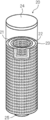
- FIG. 2 is a perspective view showing an example of a filter cartridge included in the filter unit 12.
- the filter cartridge 20 includes a cylindrical filter 21, a cylindrical core 22 that contacts the inner peripheral surface of the filter 21 and supports the filter 21, and a cylindrical sleeve that contacts the outer peripheral surface of the filter 21 and supports the filter 21. 23 and.
- the core 22 and the sleeve 23 are formed in a mesh shape so that a liquid can easily pass through.
- a cap 24 is arranged on the upper ends of the filter 21, the core 22, and the sleeve 23 to cover them. Further, at the lower end of the filter cartridge 20, an outlet 25 for letting the liquid flow out from the inside of the core 22 is arranged.
- FIG. 3 is a perspective view showing an example of the filter unit 12.
- FIG. 4 is a cross-sectional view showing an example of the filter unit 12.
- the filter unit 12 has a housing including a main body 31 and a lid 32, and a filter cartridge 20 housed in the housing.
- the lid 32 is provided with an inflow port 33 for connecting to the conduit 14 (a) and an outflow port 34 for connecting to the conduit 14 (b). Further, the lid 32 is provided with a first internal pipeline 35 connected to the inflow port 33 and a second internal pipeline 36 connected to the outlet 34.
- F 1 and F 2 indicate the transfer direction of the liquid (the liquid to be purified) in the filter unit 12.
- the liquid flows in from the inflow port 33 provided in the lid 32, flows into the inside of the main body 31 through the first internal pipeline 35 (F 1 in FIG. 4).
- the liquid that has flowed into the main body 31 passes through the filter cartridge 20. More specifically, the liquid flows in from the outer peripheral surface side of the sleeve 23, passes through the sleeve 23, the filter 21, and the core 22, and flows out from the inner peripheral surface of the core 22.
- the liquid flowing into the filter unit 12 is filtered and purified in the process of passing through the filter cartridge 20.
- the purified liquid that has flowed out near the central axis of the filter cartridge 20 is taken out of the filter cartridge 20 from the outlet 34 via the second internal conduit 36 (F 2 in FIG. 4).
- the purification device 10 includes a gas pipe (not shown) connected to the pipeline 14 (a) on the upstream side of the filter unit 12.
- gas can be supplied to the inside through a gas pipe.
- a regulating valve (not shown) for adjusting the flow rate of liquid and gas is located upstream of the branch portion where the pipeline 14 (a) and the gas pipe are connected. ) are provided respectively.
- the purification device 10 includes an exhaust pipe (not shown) connected to the pipeline 14 (b) on the downstream side of the filter unit 12. In the purification apparatus 10, gas can be discharged from the inside through the exhaust pipe.
- Each of the pipeline 14 (b) and the exhaust pipe has a regulating valve (not shown) for adjusting the flow rate of liquid and gas on the downstream side of the branch portion where the pipeline 14 (b) and the exhaust pipe are connected.
- a regulating valve (not shown) for adjusting the flow rate of liquid and gas on the downstream side of the branch portion where the pipeline 14 (b) and the exhaust pipe are connected.
- Each is provided.
- the purification apparatus 10 can perform a ventilation step (described later) for passing gas through the filter.
- the purification apparatus used in this purification method is not limited to the purification apparatus 10 having the configuration described above.
- the purification apparatus used in the present purification method may have a configuration other than the configuration described above.
- a pressure adjusting member such as a damper for adjusting the supply pressure of the liquid to the filter may be arranged on the pipe on the upstream side of the filter.
- the purification device 10 shown in FIG. 1 includes only one filter unit 12, the purification device may include a plurality of filters.
- the plurality of filters included in the purification apparatus may be arranged in series or in parallel with respect to the flow direction of the liquid.
- the purification device 10 shown in FIG. 1 has a configuration in which the purified liquid flowing out of the filter unit 12 is transferred to the filling device 13, but the purification device transfers the liquid flowing out of the filter unit 12 to the storage container 11. It may have a configuration in which it is returned and passed through the filter unit 12 again.
- a filtration method is called circulation filtration. From the viewpoint of productivity and from the viewpoint of suppressing the inclusion of impurities and other traps trapped in the filter in the liquid again, a purification method in which the liquid to be purified is passed through the filter only once without performing circulation filtration. Is preferable.
- the filter cartridge 20 shown in FIG. 2 has a filter 21, a core 22 and a sleeve 23, but the filter cartridge may have a configuration in which one or both of the core and the sleeve are not provided. .. That is, the filter cartridge may be formed only of the filter.
- the filter cartridge may have a flat or pleated filter. By using the pleated filter, the filtration area through which the liquid passes becomes wider, so that the flow rate of the liquid can be increased and the productivity can be improved.
- the purification device 10 includes the filter 21 housed in the filter cartridge 20, a filter not housed in the filter cartridge may be used.
- the purification apparatus may have, for example, a mode in which a liquid is passed through a filter formed in a flat plate shape.
- the inflow port 33 and the outflow port 34 are provided in the lid 32, but a filter unit in which the inflow port and the outflow port are provided in a member other than the lid may be used.
- the filter unit 12 shown in FIGS. 3 and 4 has a main body 31 and a lid 32, a filter unit in which the main body and the lid are integrally formed may be used.
- a gas pipe having a function of supplying gas is connected to the pipe line 14 (a), but the position where the gas pipe is connected is not particularly limited. It may be connected to an internal pipeline (upstream side or downstream side of the filter) in the filter unit and / or a pipeline on the downstream side of the filter unit. Further, in the above-mentioned purification apparatus 10, an exhaust pipe having a function of discharging gas is connected to the pipe line 14 (b), but the position where the exhaust pipe is connected is not particularly limited. For example, in the filter unit. It may be connected to an internal pipeline (upstream or downstream of the filter) and / or a pipeline upstream of the filter unit. Further, the purification device may not be provided with an exhaust pipe, and the gas may be discharged from the filling device or the downstream side of the filling device.
- the pore size of the filter is not particularly limited as long as it is used for filtering the liquid to be purified.
- the pore diameter of the filter is preferably 20 nm or less, more preferably 5 nm or less, still more preferably 2 nm or less, because the effect of the present invention is more excellent.
- the lower limit is not particularly limited, but is preferably 1 nm or more.
- the pore size of the filter is defined by the bubble point of isopropanol (IPA) or HFE-7200 (“Novec 7200”, manufactured by 3M, Hydrofluoroether, C 4 F 9 OC 2 H 5). It means the determined hole diameter.
- the material constituting the filter is not particularly limited, and for example, polyethylene (PE), polyolefin (including high density and ultrahigh molecular weight) such as polypropylene (PP); nylon (including nylon 6 and nylon 66). ) And the like; polyimide; polyamideimide; polyester such as polyethylene terephthalate; polyether sulfone; cellulose; polytetrafluoroethylene (PTFE), and a fluororesin such as perfluoroalkoxyalkane; and the above polymer (or resin). Derivatives of.
- PE polyethylene
- polyolefin including high density and ultrahigh molecular weight
- PP polypropylene
- nylon including nylon 6 and nylon 66
- polyimide polyamideimide
- polyester such as polyethylene terephthalate
- polyether sulfone cellulose
- PTFE polytetrafluoroethylene
- fluororesin such as perfluoroalkoxyalkane
- a material consisting of at least one selected from the group consisting of polyolefin, polyamide, polyimide, polyamideimide, polyester, polyethylene, cellulose, fluororesin, and derivatives thereof is preferable, and the effect of the present invention is more excellent. Therefore, polyethylene, polypropylene, nylon or fluororesin is more preferable, and PTFE is even more preferable.
- the material constituting the filter include diatomaceous earth and glass.
- the material constituting the filter may be a derivative of the above polymer.
- the derivative include those in which an ion exchange group is introduced into the polymer by a chemical modification treatment.
- the ion exchange group include a cation exchange group such as a sulfonic acid group, a carboxy group and a phosphoric acid group, and an anion exchange group such as a secondary, tertiary and quaternary ammonium group.
- the method for introducing the ion exchange group into the polymer is not particularly limited, and examples thereof include a method in which a compound having an ion exchange group and a polymerizable group is reacted with the polymer to graft the polymer.
- polyolefin polyethylene, polypropylene, etc.
- ionizing radiation ⁇ -ray, ⁇ -ray, ⁇ -ray, X-ray, electron beam, etc.
- an active moiety radical
- the irradiated polyolefin is immersed in a monomer-containing solution to graft-polymerize the monomer.
- a product in which this monomer is bonded to polyolefin as a graft polymerization side chain is produced.
- a polyolefin fiber having this monomer as a side chain is brought into contact with a compound having an anion exchange group or a cation exchange group, and the two are reacted to introduce an ion exchange group into the graft-polymerized side chain monomer.
- a compound having an anion exchange group or a cation exchange group You get things.
- an ion exchange group is not introduced into the polyolefin fiber which is the main chain, and an ion exchange group is introduced into the monomer of the side chain graft-polymerized on the main chain.
- the filter may have a configuration in which a woven fabric or non-woven fabric having an ion exchange group formed by a radiation graft polymerization method is combined with a conventional glass wool, woven fabric, or non-woven fabric.
- the filter may have a surface treatment other than chemical modification.
- the surface treatment method is not particularly limited, and a known method can be used. Examples of the surface treatment method include plasma treatment, hydrophobic treatment, coating, gas treatment, and sintering.
- Plasma treatment is preferable because the surface of the filter becomes hydrophilic.
- the water contact angle on the surface of the filter hydrophilized by plasma treatment is not particularly limited, but the static contact angle at 25 ° C. measured by a contact angle meter is preferably 60 ° or less, preferably 50 ° or less. More preferably, it is more preferably 30 ° or less.
- the pore structure of the filter is not particularly limited, and may be appropriately selected depending on the form of impurities contained in the liquid to be purified.
- the pore structure of the filter means a structure such as a pore size distribution, a positional distribution of pores in the filter, and a shape of pores, which differs depending on the method of manufacturing the filter.
- the porous film formed by sintering powder such as resin and the fiber film formed by methods such as electrospinning, electroblowing, and melt blowing have different pore structures.
- the critical surface tension of the filter is not particularly limited and can be appropriately selected depending on the impurities to be removed.
- the liquid to be purified by this purification method contains an organic solvent, and the content of each of the specific metal components is 100 mass ppt or less with respect to the total mass of the liquid to be purified.
- the liquid to be purified contains an organic solvent.
- the content of the organic solvent in the liquid to be purified is not particularly limited, but is preferably 98% by mass or more, more preferably 99% by mass or more, and 99% by mass, based on the total mass of the chemical solution, in that the effect of the present invention is more excellent. 9.9% by mass or more is more preferable.
- the upper limit is not particularly limited, but is preferably 99.999999% by mass or less.
- One type of organic solvent may be used alone, or two or more types may be used in combination. When two or more kinds of organic solvents are used in combination, the total content is preferably within the above range.
- the organic solvent is intended to be a liquid organic compound contained in a content exceeding 10,000 mass ppm per component with respect to the total mass of the chemical solution. That is, in the present specification, a liquid organic compound contained in excess of 10,000 mass ppm with respect to the total mass of the chemical solution corresponds to an organic solvent.
- a liquid is intended to be a liquid at 25 ° C. and an atmospheric pressure.
- the type of the organic solvent is not particularly limited, and a known organic solvent can be used.
- the organic solvent include alkylene glycol monoalkyl ether carboxylate, alkylene glycol monoalkyl ether, lactate alkyl ester, alkyl alkoxypropionate, cyclic lactone (preferably having 4 to 10 carbon atoms), and a monoketone which may have a ring.
- examples thereof include polar organic solvents such as compounds (preferably 4 to 10 carbon atoms), alkylene carbonates, alkyl alkoxyacetates, and alkyl pyruvates, and non-polar organic solvents such as liquid unsubstituted hydrocarbons.
- liquid unsubstituted hydrocarbon examples include linear, branched or cyclic substituted hydrocarbons having 5 to 12 carbon atoms, such as n-pentane, n-hexane, n-heptane, n-octane, and n.
- n-pentane such as n-pentane, n-hexane, n-heptane, n-octane, and n.
- n-decane, n-undecane, n-dodecane isopentane, neopentane 5-ethyl-3-methyloctane, cyclopentane, cyclohexane, methylcyclopentane, 1ethyl-3-methylcyclohexane, or a combination thereof
- n-hexane is more preferred.
- the organic solvent for example, those described in JP-A-2016-057614, JP-
- organic solvent examples include propylene glycol monomethyl ether (PGMM), propylene glycol monoethyl ether (PGME), propylene glycol monopropyl ether (PGMP), propylene glycol monomethyl ether acetate (PGMEA), ethyl lactate (EL), and methyl methoxypropionate.
- PGMM propylene glycol monomethyl ether
- PGME propylene glycol monoethyl ether
- PGMP propylene glycol monopropyl ether
- PGMEA propylene glycol monomethyl ether acetate
- EL ethyl lactate
- MCM cyclopentanone
- CyPn cyclohexanone
- ⁇ BL diisoamyl ether
- DIAE butyl acetate
- iAA isoamyl acetate
- IPA isopropanol
- MIBC 4-Methyl-2-pentanol
- 1-hexanol dimethylsulfoxide (DMSO), n-methyl-2-pyrrolidone (NMP), diethylene glycol (DEG), ethylene glycol (EG), dipropylene glycol (DPG) ), Propylene glycol (PG), ethylene carbonate (EC), propylene carbonate (PC), sulfolane, cycloheptanone, 2-heptanone (MAK), methyl ethyl ketone (MEK), hexane, or a combination thereof.
- DEG dimethylsulfoxide
- DPG dipropylene glycol
- PC propylene carbonate
- sulfolane cycl
- PGMEA ethyl propionate
- CyPn CyHe
- nBA iAA
- MAK MAK
- MEK propylene carbonate
- hexane or a combination thereof
- the type and content of the organic compound (including the organic solvent and the organic impurities described later) contained in the liquid to be purified can be measured by using a gas chromatograph mass spectrometer (GC-MS: Gas Chromatography-Mass Spectroscopy). ..
- GC-MS Gas Chromatography-Mass Spectroscopy
- the contents of each of the Fe component, Cr component, Ni component and Al component are 100 mass ppt or less with respect to the total mass of the liquid to be purified.
- the "metal component” is composed of a metal existing as particles (that is, “metal particles”) and a metal existing as ions (that is, “metal ions”) in the liquid to be purified.
- the metal particles mean, in addition to particles composed of elemental metal or alloy, a compound in which a metal such as oxide and sulfide of elemental metal or alloy and other non-metal elements are bonded.
- the metal ion means an ion of a simple substance of a metal and a complex ion (for example, an ammine complex, a cyano complex, a halogeno complex, a hydroxy complex, etc.).
- the “content of metal component” refers to the content of only the metal component containing the metal element M when a metal component (metal particles and metal ions) containing a certain metal element M is present. means.
- the metal component contains two or more kinds of metal elements
- the metal component is calculated as the content of the metal component only for the metal element having the highest content. That is, the content of the metal component containing two or more kinds of metal elements does not overlap with the content of the two or more metal components. More specifically, the content of the metal component containing Fe and Cr is not included in both the content of the Fe component and the content of the Cr component.
- the "Fe component content” refers to metal particles (Fe particles) having the highest Fe content among metal elements and metal ions (Fe) having the highest Fe content among metal elements. Ion) means the total content.
- the "Cr component content” is the total content of the metal particles (Cr particles) having the highest Cr content among the metal elements and the metal ions (Cr ions) having the highest Cr content among the metal elements. Means quantity.
- the "Ni component content” is the total content of the metal particles (Ni particles) having the highest Ni content among the metal elements and the metal ions (Ni ions) having the highest Ni content among the metal elements.
- the "Al component content” is the total content of the metal particles (Al particles) having the highest Al content among the metal elements and the metal ions (Al ions) having the highest Al content among the metal elements. Means quantity.
- the present inventors have stated that the contents of each of the Fe component, Cr component, Ni component, and Al component contained in the liquid to be purified have a particularly large effect on the removal performance of organic impurity particles of the filter.
- the content of each of the Fe component, Cr component, Ni component and Al component in the liquid to be purified is 100 mass ppt or less, the content of all metal components in the liquid to be purified is small, and such a product to be purified
- the amount of metal components captured by the filter can be reduced, and the state in which the filter is easily charged is maintained, so that it is presumed that the removal performance of organic impurity particles of the filter is improved.
- the content of each of the specific metal components in the liquid to be purified is preferably 50% by mass or less, and more preferably 10% by mass or less, in that the effect of the present invention is more excellent.
- the lower limit is not particularly limited and may be below the detection limit, preferably 0.001 mass ppt or more.
- the total content of all metal components in the liquid to be purified is preferably 5000 mass ppt (5 mass ppb) or less, and more preferably 500 mass ppt or less.
- the lower limit is not particularly limited and may be below the detection limit.
- the content of the Fe component, Cr component, Ni component, and other metal components other than the Al component in the liquid to be purified is preferably 50 mass ppt or less, more preferably 10 mass ppt or less.
- the lower limit is not particularly limited and may be below the detection limit, preferably 0.001 mass ppt or more.
- the type and content of the metal component in the liquid to be purified can be measured by the SP-ICP-MS method (Single Nano Particle Inductively Coupled Plasma Mass Spectrometry).
- the SP-ICP-MS method uses the same apparatus as the ordinary ICP-MS method (inductively coupled plasma mass spectrometry), and differs only in data analysis. Data analysis of the SP-ICP-MS method can be performed by commercially available software.
- the content of the metal component to be measured is measured regardless of its existence form. Therefore, the total mass of the metal particles to be measured and the metal ions is quantified as the content of the metal component.
- Agilent 8800 triple quadrupole ICP-MS inductively coupled plasma mass spectrometry, for semiconductor analysis, option # 200
- Agilent Technologies is described in Examples. It can be measured by the above method.
- the method for preparing the liquid to be purified in which the content of each of the specific metal components is in the above range is not particularly limited, and the metal component contained in the composition containing the organic solvent is reduced by a known purification method.
- the liquid to be purified may be prepared.
- Examples of the method for reducing the metal component contained in the composition containing the organic solvent include an ion exchange treatment, an ion adsorption treatment, and a treatment for removing metal particles.
- the ion exchange treatment is a treatment in which a composition containing an organic solvent is passed through an ion exchange unit.
- the method of passing the composition through the ion exchange unit is not particularly limited, and examples thereof include a method of passing the composition through the ion exchange unit with or without pressure.
- an ion exchange unit is arranged in a pipeline on the upstream side of the filter through which the liquid to be purified is passed, and the composition containing an organic solvent is passed through the ion exchange unit.
- the above-mentioned liquid to be purified may be prepared.
- the ion exchange unit is not particularly limited, and a known ion exchange unit can be used.
- Examples of the ion exchange unit include a unit in which an ion exchange resin is housed in a tower-shaped container (resin tower) and an electrodialysis device using an ion exchange membrane.
- a cation exchange resin or an anion exchange resin may be used in a single bed, a cation exchange resin and an anion exchange resin may be used in a double bed, or a cation exchange resin and an anion exchange may be used.
- the resin and the resin may be used in a mixed bed.
- the ion exchange resin it is preferable to use a dry resin containing as little water as possible in order to reduce the elution of water from the ion exchange resin.
- a dry resin a commercially available product can be used, and 15JS-HG / DRY (trade name, dry cation exchange resin, moisture content of 2% or less) manufactured by Organo Corporation, and MSPS2-1 / DRY (trade name, Mixed bed resin, moisture content 10% or less) can be mentioned. Further, by using an electrodialysis machine using an ion exchange membrane, processing at a high flow velocity is possible.
- the ion exchange membrane is not particularly limited, and examples thereof include Neocepta (trade name, manufactured by Astom).
- ion adsorption treatment examples include a method using an ion adsorption resin and / or a chelating agent having a function of capturing metal ions instead of the ion exchange resin already described.
- the chelating agent for example, the chelating agents described in JP-A-2016-028021 and JP-A-2000-169828 can be used.
- the ion adsorption resin for example, the resins described in JP-A-2001-123381 and JP-A-2000-328449 can be used.
- the metal particle removing treatment is a treatment for removing metal particles in a composition containing an organic solvent by using a particle removing filter.
- the form of the particle removal filter is not particularly limited, and examples thereof include a filter having a particle removal diameter of 20 nm or less.
- the particle size of the filter is preferably 1 to 15 nm.
- the particle size removal means the minimum size of particles that can be removed by the filter. For example, when the removal particle diameter of the filter is 20 nm, particles having a diameter of 20 nm or more can be removed.
- the adsorption and purification treatment step for the metal component using silicon carbide described in International Publication No. 2012/043496 may be carried out. Further, the metal component contained in the liquid to be purified may be reduced by using the filter listed as the filter used for purifying (filtering) the liquid to be purified.
- the liquid to be purified may contain components other than the above. Examples of other components include organic impurities and water.
- the liquid to be purified may contain organic impurities.
- the content of organic impurities in the liquid to be purified is not particularly limited, but is preferably 10,000 mass ppm or less, more preferably 1000 mass ppm or less, based on the total mass of the liquid to be purified.
- the lower limit is not particularly limited, but is preferably 0.1 mass ppm or more.
- the organic impurity means an organic compound different from the organic solvent and contained in a content of 10,000 mass ppm or less with respect to the total mass of the liquid to be purified.
- the organic compound contained in a content of 10,000 mass ppm or less with respect to the total mass of the liquid to be purified corresponds to an organic impurity and does not correspond to an organic solvent.
- each of the plurality of organic compounds is contained in the liquid to be purified at a content of 10,000 mass ppm or less with respect to the total mass of the liquid to be purified, each of them corresponds to an organic impurity.
- Organic impurities are often mixed or added to the liquid to be purified in the process of synthesizing, purifying and / or transferring the organic solvent contained in the liquid to be purified.
- organic impurities include plasticizers, antioxidants, and compounds derived from them (eg, decomposition products).
- the plasticizer may be eluted into the organic solvent from the wetted parts of each unit (reaction unit, distillation column, filter unit, etc.) of the equipment (refining equipment) used for purification. be.
- the antioxidant may be intentionally added to the organic solvent, or may be mixed in the commercially available organic solvent when purchased and used.
- the organic impurities of these components those having a high boiling point (hereinafter, also referred to as “high boiling point organic impurities”) are hard to volatilize and therefore easily remain as organic impurity particles on the substrate surface, which causes defects in semiconductor devices.
- the content of high boiling point organic impurities (particularly, organic impurities having a boiling point of 250 ° C. or higher) in the liquid to be purified is preferably 1 mass ppm or less, more preferably 50 mass ppb or less, based on the total mass of the liquid to be purified. It is more preferably 10 mass ppb or less.
- the lower limit is not particularly limited, but is preferably 10 mass ppt or more.
- High boiling point organic impurities include dioctyl phthalate (DOP, boiling point 385 ° C.), diisononyl phthalate (DINP, boiling point 403 ° C.), dioctyl adipate (DOA, boiling point 335 ° C.), dibutyl phthalate (DBP, boiling point 340 ° C.). And ethylene propylene rubber (EPDM, boiling point 300-450 ° C.).
- the content of dioctyl phthalate (DOP) in the liquid to be purified is preferably 10 mass ppb or less, more preferably 5 mass ppb or less, based on the total mass of the liquid to be purified, in that the effect of the present invention is more excellent. It is preferable, and 1 mass ppb or less is more preferable.
- the lower limit is not particularly limited, but is preferably 10 mass ppt or more.
- the liquid to be purified may contain water.
- the content of water in the liquid to be purified is not particularly limited, but is preferably 100 mass ppm or less with respect to the total mass of the liquid to be purified.
- the lower limit is not particularly limited, but is preferably 10 mass ppm or more.
- the water content in the liquid to be purified means the water content measured by using a device based on the Karl Fischer water content measurement method.
- a ventilation step is performed in which gas is supplied to the pipeline and the gas is passed through the filter.
- the aeration step is performed to remove the moisture remaining on the filter.
- the water remaining in the filter is considered to be derived from, for example, the manufacturing process of the filter. Further, by passing the gas through the filter in the ventilation step, other impurities and / or stains remaining on the filter can be removed.
- the method of supplying the gas to the pipeline is not particularly limited as long as the gas can pass through the voids of the filter.
- the filter is provided via the gas pipe.
- the ventilation step can be performed by supplying gas into the filter cartridge and discharging the gas that has passed through the filter through the exhaust pipe.
- the position where the gas is supplied in the purification apparatus may be in the filter unit and / or in the pipeline on the downstream side of the filter unit. Further, the position where the gas is discharged in the purification device may be in the filter unit, in the pipeline on the upstream side of the filter unit, and / or on the downstream side of the filling device.
- the gas used in the aeration step is not particularly limited as long as it is a compound that is a gas at 25 ° C. and atmospheric pressure, and examples thereof include polar gas and non-polar organic compound gas.
- the polar gas include carbon dioxide, ammonia and volatile amines, with carbon dioxide or ammonia being preferred.
- the gas of the non-polar organic compound include hydrocarbons such as methane, ethane, propane and butane, and halogenated hydrocarbons in which at least one hydrogen atom of these hydrocarbons is replaced with a halogen atom. Be done.
- halogen atom contained in the halogenated hydrocarbon examples include a fluorine atom, a chlorine atom, an iodine atom and a bromine atom, and a fluorine atom or a chlorine atom is preferable, and a fluorine atom is more preferable.
- the halogenated hydrocarbon examples include chloromethane, trichloromethane, carbon tetrachloride (tetrachloromethane), fluoromethane, difluoromethane, trifluoromethane, tetrafluoromethane, fluoroethane, difluoroethane, trifluoroethane and tetrafluoroethane.
- an inert gas such as nitrogen and argon, and dry air may be used.
- the above gas may be used alone or in combination of two or more.
- a gas having a polarity close to the polarity of the liquid to be purified used in the purification step described later.
- a gas having a polarity close to that of the liquid to be purified is used, at least a part of the gas remaining in the voids in the filter cartridge is dissolved in the liquid to be purified, so that the liquid to be purified infiltrates the filter cartridge at a high speed.
- the faster the liquid to be purified infiltrates the filter cartridge the shorter the time required to fill the voids in the filter with the liquid to be purified, and the filtration efficiency of the filter can be maximized. Filtration performance can be improved.
- the cleaning step described later it is preferable to use a gas having a polarity close to the polarity of the cleaning liquid in the aeration step for the same reason as described above.
- the liquid to be purified or the cleaning liquid is a polar organic solvent
- a polar gas more preferably carbon dioxide or ammonia, and further preferably carbon dioxide in the aeration step.
- the polar organic solvent include the compounds described as the polar organic solvent contained in the above-mentioned liquid to be purified, including the preferred embodiment thereof.
- the liquid to be purified or the cleaning liquid is a non-polar organic solvent, it is preferable to use a gas of a non-polar organic compound in the aeration step.
- non-polar organic solvent examples include compounds listed as non-polar organic solvents among the organic solvents contained in the above-mentioned liquid to be purified, such as n-pentane, n-hexane, n-heptane, n-octane, and n.
- n-pentane n-hexane
- n-heptane n-heptane
- n-octane n.
- n-Nonan, n-decane, n-undecane, n-dodecane, or a combination thereof is preferable, and n-hexane is more preferable.
- the degree of removal of water remaining in the filter by the ventilation process can be specified by collecting and analyzing the exhaust gas discharged from the pipeline. Exhaust analysis can be performed by GC-MS.
- the time for performing the aeration step is not particularly limited, but is preferably 1 to 120 minutes in terms of excellent balance between the removal of water in the filter and the efficiency of the entire purification method.
- the gas supply pressure and flow rate to the filter in the ventilation step are not particularly limited, and may be appropriately set according to the pressure resistance of each member provided in the purification device such as the filter, the pipeline and the regulating valve.
- the pressure on the upstream side of the filter is preferably 0.01 to 0.34 MPa.
- the flow rate of the gas with respect to the filter in the ventilation step is preferably 0.05 to 5 L / s.
- the temperature of the gas passed through the filter in the aeration step is, for example, 10 to 50 ° C.
- the number of aeration steps is not particularly limited, and may be only once or may be two or more.
- a depressurization step may be performed before and / or after the aeration step to reduce the pressure inside the conduit in which the filter is arranged (for example, inside the filter cartridge). By reducing the pressure inside the filter cartridge, the residual water content in the filter can be further reduced.
- the depressurization step may be either before or after the ventilation step. Further, the depressurizing step and the aeration step may be repeated.
- the method for carrying out the depressurization step is not particularly limited, and for example, a known vacuum pump may be connected to the exhaust pipe provided in the purification apparatus to depressurize the inside of the pipeline in which the filter is arranged.
- the degree of depressurization is not particularly limited, and may be appropriately set according to the pressure resistance of each member provided in the purification device such as a filter, a pipeline, and a regulating valve.
- This purification method includes a purification step of filtering a liquid to be purified using a filter through which gas is passed by a ventilation step. Impurities contained in the liquid to be purified are removed by a filter in the purification step of the liquid to be purified. As a result, a purified chemical solution is produced.
- the liquid to be purified, which is filtered by the purification step, is as described above.
- the liquid to be purified stored in the storage container 11 is sent out to the filter unit 12 having the filter 21 via the conduit 14.
- a specific example of the method of transferring the liquid to be purified to the filter 21 will be described later.
- the liquid to be purified delivered to the filter unit 12 flows into the inside of the main body 31 through the inflow port 33 and the first internal pipeline 35, and passes through the filter cartridge 20.
- the filter 21 constituting the filter cartridge 20 When passing through the filter 21 constituting the filter cartridge 20, the liquid to be purified is filtered and purified.
- the purified chemical solution flowing out of the filter cartridge 20 is discharged from the filter unit 12 via the second internal conduit 36 and the outlet 34.
- the chemical solution discharged from the filter unit 12 is sent to the filling device 13 via the conduit 14, and is stored in a container for storing and / or transporting the chemical solution.
- ⁇ Transfer method of liquid to be purified> As a method of transferring the liquid to be purified stored in the storage container to the filter via the pipeline, for example, a method using a pump provided on the pipeline, a method of introducing a pumping gas into the storage container, and a method of introducing a pumping gas into the storage container. A method of depressurizing the inside of the pipeline on the downstream side of the filter can be mentioned.
- the liquid to be purified stored in the storage container may be transferred to the filter by using a pump provided on the pipeline.
- the position where the pump is provided is not particularly limited and may be on the upstream side or the downstream side of the filter on the pipeline, but the upstream side is preferable. Further, the number of pumps used may be one or a combination of two or more.
- the supply pressure of the liquid to be purified when the liquid to be purified is transferred using a pump is not particularly limited, but the pressure inside the pipeline on the upstream side of the filter is preferably 0.00010 to 1.0 MPa, which is 0. More preferably, it is 0.01 to 0.34 Mpa. Further, since the filtration pressure affects the filtration accuracy, it is preferable that the pulsation of the supply pressure of the liquid to be purified to the filter is as small as possible.
- a method of reducing the pulsation of the supply pressure of the liquid to be purified a method of using a regulating valve and / or a damper arranged in the pipeline on the upstream side of the filter can be mentioned.
- the liquid to be purified stored in the storage container may be transferred to the filter by introducing a pumping gas into the storage container to increase the pressure of the liquid to be purified. More specifically, a pumping gas is introduced into the storage container from a gas pipe connected to the storage container, the purified liquid is pushed out by the introduced pumping gas, and the purified liquid is passed through a filter. be able to.
- the pumping liquid is transferred using the pumping gas, if residual gas is present in the voids inside the filter cartridge, the pumping gas dissolved in the purified liquid vaporizes in the vicinity of the residual gas and pushes out the residual gas. As a result, it is presumed that the filtration performance of the liquid to be purified by this purification method can be improved.
- the supply pressure and flow rate of the gas to the purification device in the transfer process of the liquid to be purified using the pumping gas are not particularly limited, and depend on the pressure resistance of each member provided in the purification device such as a filter, a pipeline and a regulating valve. It may be set appropriately.
- the gas supply pressure in the transfer process using the pumping gas the pressure of the pumping gas before contacting with the liquid to be purified at the time of pumping is preferably 0.01 to 0.34 MPa.
- the pumping gas is not particularly limited as long as it is a compound that is a gas at 25 ° C. and atmospheric pressure, and examples thereof include a polar gas and a non-polar organic compound gas.
- the polar gas include carbon dioxide, ammonia and volatile amines, with carbon dioxide or ammonia being preferred.
- the gas of the non-polar organic compound include the compounds described as the gas used in the aeration step, including its preferred embodiment.
- an inert gas such as nitrogen and argon, and dry air may be used. Further, as the pumping gas, the above-mentioned gas may be used alone or in combination of two or more.
- the liquid to be purified may be transferred to the filter by a depressurization treatment in which at least a part of the inside of the pipeline on the downstream side of the filter is depressurized.
- the inside of the filter unit is filled with the liquid to be purified or the cleaning liquid
- the adjusting valve arranged on the pipeline connecting the filter unit and the filling device is closed, and the adjusting valve is used.
- Another method is to open the regulating valve after decompressing the inside of the pipeline on the downstream side using a decompression device.
- a regulating valve arranged on the pipeline connecting the storage container and the filter unit is closed, and a pressure reducing device is used inside the pipeline on the downstream side of the regulating valve (including the filter unit).
- a method of opening the regulating valve after depressurizing the pressure can be mentioned.
- the liquid to be purified stored in the storage container is transferred to the filter unit and passes through the filter.
- the arrangement of the decompression device is not particularly limited as long as it is connected to the decompression region in the pipeline.
- the decompression device may be connected to the exhaust pipe connected to the pipeline on the downstream side of the filter. Can be mentioned. Further, the decompression device may be arranged on the downstream side of the filling device.
- the depressurizing device used for the depressurizing treatment a known device such as a vacuum pump is used.
- the pressure in the depressurized region inside the pipeline is not particularly limited as long as it is lower than the pressure inside the pipeline on the upstream side, but 100 Pa or less is preferable, and the present invention. 50 Pa or less is more preferable, 1 Pa or less is further preferable, and 0.1 Pa or less is particularly preferable.
- the lower limit of the pressure inside the pipeline to be depressurized is not particularly limited as long as the members such as the filter, the pipeline and the regulating valve have pressure resistance, but 0.01 Pa or more is preferable.
- the method of introducing the pumping gas into the storage container described above or the method of depressurizing treatment described above is preferable.
- the temperature at which the liquid to be purified is passed through the filter is not particularly limited, but may be 0 to 50 ° C, preferably 0 to 25 ° C.
- the filtration rate of the liquid to be purified passing through the filter is not particularly limited, but the flow rate (L / min) per filtration area of the filter is preferably 0.6 L / min / m 2 or more, and 0.75 L / min / m 2. The above is more preferable, and 1.0 L / min / m 2 or more is further preferable.
- the filter has a differential pressure resistance that guarantees filter performance (the filter does not break), and if this value is large, the filtration rate can be increased by increasing the filtration pressure.
- the upper limit of the filtration rate depends on the differential pressure resistance of the filter, but is preferably 10.0 L / min / m 2 or less.
- the purification step of the chemical solution may further include a step of distilling the solution to be purified after or before the purification step.
- the method for purifying the chemical solution may include steps other than the above. Examples of other steps include a cleaning step, a moisture adjusting step, and a static elimination step. In the following, each step will be described in detail.
- the present purification method may further include a cleaning step of passing the cleaning liquid through the filter to clean the filter after the aeration step and before the purification step, and the content of impurities in the purified chemical solution. It is preferable to further have a cleaning step in that the above can be suppressed.
- the cleaning step is not particularly limited as long as it is a method of cleaning the filter with a cleaning liquid, and examples thereof include a method of immersing the filter in the cleaning liquid, passing the cleaning liquid through the filter, and a method of combining these.
- the filter constitutes a filter cartridge
- the voids in the filter can be filled with the cleaning liquid to remove the gas contained in the voids in that the filtration efficiency of the filter can be improved and the purification efficiency of the chemical solution by this purification method can be improved. preferable.
- the cleaning liquid is not particularly limited, but an organic solvent is preferable.
- the organic solvent used as the cleaning liquid is the same as the compound described as the organic solvent contained in the above-mentioned purified liquid, including its preferred embodiment.
- the cleaning liquid used in the cleaning step may be the same as or different from the liquid to be purified in the subsequent purification step, but the rinsing treatment using the liquid to be purified is not required. Therefore, it is preferable that it is the same as the liquid to be purified.
- the method for transferring the cleaning liquid in the cleaning step is not particularly limited, and the cleaning liquid can be transferred inside the pipeline and passed through the filter according to the method described as the method for transferring the liquid to be purified in the purification step.
- the supply pressure of the cleaning liquid when the cleaning liquid is passed through the filter is not particularly limited, and for example, the pressure on the upstream side of the filter inside the pipeline may be 0.0001 to 1.0 MPa.
- the pressure on the upstream side of the filter inside the pipeline is preferably 0.10 to 0.34 MPa, more preferably 0.15 to 0.34 MPa, and 0.25 to 0.25 to 0.25 to 0.25 to 0.34 MPa, more preferably 0.15 to 0.34 MPa, in terms of improving the cleaning efficiency with the cleaning liquid. 0.34 MPa is more preferable.
- the timing for ending the cleaning step is not particularly limited, and the cleaning step may be terminated after confirming that the amount of impurities eluted from the filter into the cleaning liquid is saturated.
- Examples of the above confirmation method include the following methods.
- the cleaning liquid that has passed through the filter is collected, the obtained sample liquid is applied to the surface of the wafer, the coating film is dried, and then the number of defects generated on the wafer surface is measured. When the number of measured defects does not increase, it is judged that the amount of impurities eluted from the filter into the cleaning liquid is saturated.
- the apparatus used for measuring the number of defects is not particularly limited, and a known inspection apparatus such as a wafer surface inspection apparatus “Surfscan SP5” (manufactured by KLA Tencor) can be used.
- the flow rate of the cleaning liquid passed through the filter in the cleaning step is not particularly limited, but the flow rate (L / min) per filtration area of the filter is preferably 0.6 to 10.0 L / min / m 2.
- the temperature of the cleaning liquid used in the cleaning step is not particularly limited, but is preferably 0 to 50 ° C.
- the number of cleaning steps is not particularly limited, and may be performed only once or twice or more.
- the water content adjusting step is a step of adjusting the content of water in the liquid to be purified.
- the method for adjusting the water content include a method for removing water in the liquid to be purified.
- the method for removing water is not particularly limited, and a known dehydration method can be used.
- the method for removing water include a dehydration membrane, a water adsorbent insoluble in an organic solvent, an aquatic replacement device using a dry inert gas, and a heating or vacuum heating device.
- PV osmotic vaporization
- VP vapor permeation
- the dehydrated membrane is configured as, for example, a permeable membrane module.
- a membrane made of a polymer-based material such as polyimide-based, cellulosic-based and polyvinyl alcohol-based, or an inorganic material such as zeolite can be used.
- the water adsorbent is used by adding it to the liquid to be purified.
- the water adsorbent include zeolite, diphosphorus pentoxide, silica gel, calcium chloride, sodium sulfate, magnesium sulfate, anhydrous zinc chloride, fuming sulfuric acid and soda lime.
- zeolite particularly, molecular sieve (trade name) manufactured by Union Showa Co., Ltd.
- olefins can also be removed.
- the static elimination step is a step of reducing the charging potential of the liquid to be purified by removing static electricity from the liquid to be purified.
- the static elimination method is not particularly limited, and a known static elimination method can be used.
- Examples of the static elimination method include a method of bringing the liquid to be purified into contact with the conductive material.
- the contact time for bringing the liquid to be purified into contact with the conductive material is preferably 0.001 to 60 seconds, more preferably 0.001 to 1 second, still more preferably 0.01 to 0.1 seconds.
- Conductive materials include stainless steel, gold, platinum, diamond, and glassy carbon.
- Examples of the method of bringing the liquid to be purified into contact with the conductive material include a method of arranging a grounded mesh made of the conductive material inside the conduit and passing the liquid to be purified through the grounded mesh.
- each step already described is preferably performed in a closed state and in an inert gas atmosphere in which water is unlikely to be mixed in the liquid to be purified, and the dew point temperature is to be suppressed as much as possible in order to suppress the mixing of water as much as possible.
- the clean room preferably meets the 14644-1 clean room standard. It is preferable to satisfy any one of ISO (International Organization for Standardization) class 1, ISO class 2, ISO class 3, and ISO class 4, more preferably ISO class 1 or ISO class 2, and satisfy ISO class 1. Is even more preferable.
- ISO International Organization for Standardization
- the chemical solution of the present invention is a chemical solution produced by a method for producing a chemical solution having the above-mentioned purification method for purifying a product to be purified to obtain a chemical solution.
- the chemical solution contains an organic solvent.
- the content of the organic solvent in the chemical solution is not particularly limited, but is preferably 99.0% by mass or more, more preferably 99.9% by mass or more, and further 99.99% by mass or more, based on the total mass of the chemical solution. preferable.
- the organic solvent one type may be used alone, or two or more types may be used in combination. When two or more kinds of organic solvents are used in combination, the total content is preferably within the above range.
- the organic solvent contained in the chemical solution may be the same as the organic solvent contained in the product to be purified, including its preferred embodiment.
- the chemical solution may contain a specific metal component, or may contain a metal component other than the specific metal component.
- the specific metal component and other metal components contained in the chemical solution may be the same as the specific metal component and other metal components contained in the product to be purified as described above, including their preferred embodiments.
- the chemical solution may contain organic impurities.
- the organic impurities contained in the chemical solution may be the same as the organic impurities contained in the product to be purified, including its preferred embodiment.
- the chemical solution purified by the above purification method is preferably used for manufacturing semiconductor devices. Specifically, it is preferably used for processing using an organic substance in a wiring forming process including photolithography (including a lithography process, an etching process, an ion implantation process, and a peeling process). More specifically, it is preferably used as a pre-wet solution, a developing solution, a rinsing solution, a stripping solution, a CMP slurry, and a rinsing solution after CMP (p-CMP rinsing solution).
- the rinsing liquid for example, it can be used for rinsing the edge erase of the wafer before and after applying the resist liquid.
- the chemical solution can also be used as a diluent for the resin contained in the resist film forming composition (resist composition) used for manufacturing semiconductor devices. That is, it can be used as a solvent for a composition for forming a resist film. Further, the above chemical solution may be diluted with another organic solvent and / or a solvent such as water before use. When the chemical solution is used as a CMP slurry, for example, additives such as abrasive grains and an oxidizing agent may be added to the chemical solution. It can also be used as a solvent when diluting the CMP slurry.
- the chemical solution can be suitably used for applications other than those for manufacturing semiconductor devices, and can also be used as a developing solution such as a polyimide, a resist for a sensor, a resist for a lens, and a rinsing solution.
- the chemical solution can also be used as a solvent for medical use or cleaning use.
- it can be suitably used for cleaning members such as containers, pipes, and substrates (for example, wafers and glass).
- the chemical solution may be temporarily stored in a container until use.
- the container for storing the chemical solution is not particularly limited, and a known container can be used.
- the container for storing the chemical solution it is preferable that the container has a high degree of cleanliness and less elution of impurities for semiconductor device manufacturing applications.
- usable containers include, but are not limited to, the "clean bottle” series manufactured by Aicello Chemical Corporation and the "pure bottle” manufactured by Kodama Resin Industry.
- a multi-layer bottle having a 6-layer structure with 6 types of resin or a multi-layer bottle with a 7-layer structure with 6 types of resin is used for the purpose of preventing impurities from being mixed in the chemical solution. It is also preferable.
- these containers include the containers described in Japanese Patent Application Laid-Open No. 2015-123351.
- the wetted portion of this container is formed of a non-metal material or an electropolished metal material.
- a fluorine-containing resin material such as polyethylene resin, polypropylene resin, polyethylene-polypropylene resin, or perfluoro resin is preferable, and a fluorine-containing resin is more preferable from the viewpoint of less elution of metal atoms.
- fluorine-containing resin examples include perfluoro resin, tetrafluoride ethylene resin (PTFE), tetrafluoride ethylene / perfluoroalkyl vinyl ether copolymer (PFA), and tetrafluoride ethylene-hexfluoride propylene copolymer.
- Resin FEP
- EFE ethylene tetrafluoride-ethylene copolymer resin
- ECTFE ethylene trifluoride-ethylene copolymer resin
- PVDF vinylidene fluoride resin
- ETFE ethylene trifluoride copolymer resin
- PCTFE vinyl fluoride resin
- an ethylene tetrafluoride resin an ethylene tetrafluoride / perfluoroalkyl vinyl ether copolymer, or an ethylene tetrafluoride-propylene hexafluoride copolymer resin is preferable.
- a container in which the wetted portion is polyfluorocarbon When a container in which the wetted portion is polyfluorocarbon is used, elution of ethylene or propylene oligomer can be suppressed as compared with the case where a container in which the wetted portion is made of polyethylene resin, polypropylene resin, or polyethylene-polypropylene resin is used.
- a container in which the wetted portion is polyfluorocarbon include, for example, a Fluoro Pure PFA composite drum manufactured by Entegris.
- the containers described on pages 4 of JP-A-3-502677, page 3 of International Publication No. 2004/016526, and pages 9 and 16 of International Publication No. 99/046309 shall also be used. Can be done.
- it is used as a wetted portion of a non-metal material it is preferable that elution of the non-metal material into a chemical solution is suppressed.
- the metal material examples include metal materials in which the total content of chromium and nickel is more than 25% by mass with respect to the total mass of the metal material, and among them, 30% by mass or more is preferable.
- the upper limit of the total content of chromium and nickel in the metal material is not particularly limited, but is preferably 90% by mass or less.
- the metal material include stainless steel, carbon steel, alloy steel, nickel-chromium molybdenum steel, chrome steel, chrome molybdenum steel, manganese steel, and nickel-chrome alloy.
- the stainless steel is not particularly limited, and known stainless steel can be used. Among them, an alloy containing 8% by mass or more of nickel is preferable, and an austenitic stainless steel containing 8% by mass or more of nickel is more preferable.
- austenitic stainless steels include SUS (Steel Use Stainless) 304 (Ni content 8% by mass, Cr content 18% by mass), SUS304L (Ni content 9% by mass, Cr content 18% by mass), and SUS316. (Ni content 10% by mass, Cr content 16% by mass), and SUS316L (Ni content 12% by mass, Cr content 16% by mass).
- the nickel-chromium alloy is not particularly limited, and a known nickel-chromium alloy can be used. Of these, nickel-chromium alloys having a nickel content of 40 to 75% by mass and a chromium content of 1 to 30% by mass are preferable. Examples of the nickel-chromium alloy include Hastelloy (trade name, the same shall apply hereinafter), Monel (trade name, the same shall apply hereinafter), and Inconel (trade name, the same shall apply hereinafter).
- Hastelloy C-276 Ni content 63% by mass, Cr content 16% by mass
- Hastelloy-C Ni content 60% by mass, Cr content 17% by mass
- Hastelloy C- 22 Ni content 61% by mass, Cr content 22% by mass
- the nickel-chromium alloy may further contain at least one selected from the group consisting of boron, silicon, tungsten, molybdenum, copper, and cobalt, in addition to the alloys described above, if necessary. good.
- the method of electrolytic polishing a metal material is not particularly limited, and a known method can be used. For example, it can be carried out by the method described in paragraphs 0011 to 0014 of JP2015-227501 and paragraphs 0036 to 0042 of JP2008-264929.
- the content of chromium in the passivation layer on the surface of the metal material is higher than the content of chromium in the matrix by electropolishing. Therefore, a metal component containing a metal atom does not easily flow out into the organic solvent from a refining apparatus in which the wetted portion is formed of an electrolytically polished metal material, so that an organic solvent having a reduced impurity content can be obtained. It is presumed that it can be done.
- the metal material may be buffed.
- the method of buffing is not particularly limited, and a known method can be used.
- the size of the abrasive grains used for finishing the buffing is not particularly limited, but # 400 or less is preferable because the unevenness on the surface of the metal material tends to be smaller.
- the buffing is preferably performed before the electrolytic polishing.
- the inside of the container is cleaned before containing the chemical solution.
- the above-mentioned chemical solution itself or a diluted solution of the above-mentioned chemical solution is preferable.
- the chemical solution may be bottling, transported and / or stored in a container such as a gallon bottle or a coated bottle after production.
- the gallon bottle may or may not be made of glass material.
- the inside of the container may be replaced with an inert gas (nitrogen, argon, etc.) having a purity of 99.99995% by volume or more for the purpose of preventing changes in the components in the solution during storage.
- an inert gas nitrogen, argon, etc.
- a gas having a low water content is preferable.
- the temperature may be normal temperature, but the temperature may be controlled in the range of ⁇ 20 ° C. to 30 ° C. in order to prevent deterioration.
- the present invention will be described in more detail based on Examples.
- the materials, amounts used, ratios, treatment contents, treatment procedures, etc. shown in the following examples can be appropriately changed as long as they do not deviate from the gist of the present invention. Therefore, the scope of the present invention should not be construed as limiting by the examples shown below.
- the object to be measured purified solution or chemical solution
- the object to be measured was concentrated or diluted using a washed glass instrument for measurement.
- the liquid to be purified was also used as the cleaning liquid in the cleaning step. means.
- the content of the organic solvent in the cleaning liquid is 99 to 99.9 with respect to the total mass of the cleaning liquid. It was% by mass.
- a quartz torch, a coaxial PFA (perfluoroalkoxy alkane) nebulizer (for self-priming), and a platinum interface cone were used as the sample introduction system.
- the measurement parameters of the cool plasma condition are as follows.
- a filter material composed of the following materials was used.
- PTFE Polytetrafluoroethylene
- PE Polyethylene
- PP polypropylene
- a commercially available organic solvent was prepared and purified using the following purification apparatus to prepare a liquid to be purified used in each Example and each Comparative Example.
- a purification device was prepared.
- the filtration device is composed of three filter units arranged in series on the pipeline and does not have a regulating valve. The following filters were arranged in order from the upstream side (primary side) in the filtration device.
- the return pipeline has a function of returning the organic solvent that has passed through the filtration device to the container.
- the wetted portion of the purification apparatus was thoroughly washed with an organic solvent, and then the purified liquid to be purified was prepared using the washed purification apparatus.
- the pump placed on the pipeline connecting the container and the filtration device was operated to send the organic solvent from the container to the filtration device.
- the filtered organic solvent was returned to the container via the return pipe.
- the return of the filtered organic solvent was repeated 3 times. That is, the filtered organic solvent was returned to the container until the amount of liquid passed through the filtration device exceeded three times the amount of the organic solvent filled in the container before purification. Then, the filtered organic solvent was discharged from the discharge port to obtain a liquid to be purified used in each Example and each Comparative Example.
- Example 1 As shown in FIG. 1, a purification device including a storage container, a filling device, a pipeline connecting the storage container and the filling device, and a filter unit arranged on the pipeline was prepared. A filter cartridge having a filter having a pore diameter of 15 nm was housed in the filter unit. The material (filter material) constituting the filter was polytetrafluoroethylene (PTFE).
- PTFE polytetrafluoroethylene
- each of the organic solvent, all metal components including the specific metal component, and dioctyl phthalate contained in the liquid to be purified by the above purification method are measured in the liquid to be purified by the above measurement method, and then stored. 100 L of the liquid to be purified was stored in the container.
- CO 2 carbon dioxide
- the flow rate of the CO 2 gas was 1.8 L / s, and the pressure of the CO 2 gas was 0.1 MPa.
- a cleaning step of cleaning the filter cartridge was carried out by operating a pump arranged on a pipeline connecting the storage container and the filter unit and sending a liquid to be purified from the storage container to the filter unit.
- the pressure inside the pipeline on the upstream side of the filter unit was adjusted to 0.10 MPa.
- the cleaning liquid that passed through the filter cartridge was not sent to the filling device and was discarded.
- the cleaning liquid that has passed through the filter unit is collected, the obtained sample liquid is applied to the surface of the wafer, the coating film is dried, and then the number of defects generated on the wafer surface is measured by the surface inspection device "Surfscan SP5" on the wafer. (Manufactured by KLA Tencor).
- the cleaning step was carried out until the number of defects measured by the above method did not increase, that is, until the amount of impurities eluted from the filter unit into the cleaning liquid did not increase.
- a purification step of filtering the purified liquid using a filter cartridge was carried out by operating a pump arranged in the pipeline and sending the purified liquid from the storage container to the filter unit. At this time, the pressure inside the pipeline on the upstream side of the filter unit was adjusted to 0.10 MPa. The purified chemical solution filtered by the filter cartridge and transferred from the filter unit was sent to the filling device via a conduit.
- Examples 2 to 67, Comparative Examples 1 to 3 Purified according to the method described in Example 1, except that the liquid to be purified and the filter shown in Table 1 were used, and the aeration step, the washing step, and the purification step were performed under the conditions shown in Table 1. The solution was purified to obtain a purified drug solution. The following evaluations were carried out using the chemical solutions obtained in each Example and each Comparative Example.
- “Decompression 1” to “Decompression 3” in the “Purification step” column of Table 1 are used in the inside of the conduit instead of the method of transferring the liquid to be purified using the pump performed in the purification step of Example 1. It means that the liquid to be purified stored in the storage container was transferred and passed through the filter by the depressurization treatment in which at least a part of the downstream side of the filter was depressurized. More specifically, after filling the inside of the filter unit with a cleaning liquid by the above cleaning step, the adjusting valve arranged on the pipeline connecting the filter unit and the filling device is closed, and the pipeline on the downstream side of the adjusting valve is closed. The inside of the was reduced to the following pressure using a vacuum pump. Then, by opening the regulating valve, the cleaning liquid in the filter unit was transferred to the filling device, and then the liquid to be purified stored in the storage container was transferred to the filter unit and passed through the filter.
- the substrate was set in a spin discharge device, and while rotating the substrate, the liquid to be purified before each purification method was carried out was discharged to the surface of the substrate at a flow velocity of 1 mL / s. Then, the substrate was spin-dried. Using the above inspection device, the number of organic residues having a diameter of 19 nm or more existing on the substrate after the liquid to be purified was applied was measured (this is used as a measured value). The difference between the initial value and the measured value (measured value-initial value) was calculated and used as the amount of organic residue A1 derived from the liquid to be purified before purification.
- EDX Error dispersive X-
- SEMVision G6 defect analysis device
- Elemental analysis was performed by ray spectroscopy (energy dispersive X-ray analysis). By this method, it was confirmed that the particles measured as the organic residue did not contain a metal component.
- the initial value and the measured value are measured according to the same method as described above, and the measured particles are organic residues containing no metal component.
- the difference between the obtained initial value and the measured value (measured value-initial value) was calculated to obtain the amount of organic residue A2 derived from the purified chemical solution.
- each Example and each comparative example using the formula ((A1-A2) / A1).
- the removal rate (%) of the organic residue by the purification method of was calculated.
- the calculated removal rate of the organic residue is shown in Table 1. The higher the removal rate of organic residues, the higher the performance of removing organic impurity particles in the liquid to be purified means.
- Table 1 shows the composition of the liquid to be purified used in each Example and each comparative example, the filter medium and pore size of the filter, the type of gas used in the aeration step, the conditions of the cleaning step (the type of cleaning liquid used, and the filter). The pressure on the upstream side of the cartridge), the method of the purification process, and the above evaluation results are shown.
- the "Type” column and “Amount (%)" column of "Organic solvent” in Table 1 indicate the type of organic solvent used in each Example and each Comparative Example, and the content (unit) with respect to the total mass of the liquid to be purified. : Mass%).
- the content of the mixed solvent A that is, the total content of butyl acetate and propylene carbonate was 99.99% by mass with respect to the total mass of the liquids to be purified. It means that.
- the "Fe (ppt)” column, “Cr (ppt)” column, “Ni (ppt)” column, and “Al (ppt)” column of “metal components” are the Fe components with respect to the total mass of the liquid to be purified.
- Content total content of Fe particles and Fe ions
- Cr component content total content of Cr particles and Cr ions
- Ni component content total content of Ni particles and Ni ions
- Al total content of Al particles and Al ions
- total amount (pt) column indicates the total content (unit: mass ppt) of all metal components (metal particles and metal ions) with respect to the total mass of the liquid to be purified.
- the content of metal components other than the specific metal component contained in the liquid to be purified used in each example was measured.
- the content per metal component with respect to the total mass of the liquid to be purified was 10 mass ppt or less in Examples 1, 2 and 6 to 67, and Example 3 In each of ⁇ 5, it was 50 mass ppt or less.
- the “Dioctyl phthalate (ppb)” column in Table 1 shows the content of dioctyl phthalate (unit: mass ppb) with respect to the total mass of the liquid to be purified used in each Example and each Comparative Example.
- the balance other than the above components contained in the liquids to be purified in each Example and each Comparative Example were organic impurities.
- the pumping gas is carbon dioxide, ethane, propane, butane, butane and propane in a volume ratio of 1: 1. It was confirmed that the mixed gas or propane had better organic impurity particle removing performance (see comparison between Examples 14 and 50 to 65).
- the purification step when the liquid to be purified is transferred by the depressurization treatment, it has been confirmed that the organic impurity particle removing performance is more excellent when the pressure inside the depressurizing conduit is 50 Pa or less (Examples 16 and 15). (Refer to the comparison with), it was confirmed that the organic impurity particle removing performance was further excellent when the pressure inside the depressurizing pipeline was 0.1 Pa or less (see the comparison between Example 17 and Example 16).
- Purification equipment 11 Storage container 12 Filter unit 13 Filling equipment 14 Pipeline 20 Filter cartridge 21 Filter 22 Core 23 Sleeve 24 Cap 25 Outlet 31 Main body 32 Lid 33 Inlet 34 Outlet 35 1st internal pipeline 36 2nd internal pipeline
Landscapes
- Chemical & Material Sciences (AREA)
- Chemical Kinetics & Catalysis (AREA)
- Engineering & Computer Science (AREA)
- Water Supply & Treatment (AREA)
- Separation Using Semi-Permeable Membranes (AREA)
- Cleaning Or Drying Semiconductors (AREA)
Abstract
本発明は、薬液中の有機不純物粒子の除去性能が優れる、薬液の精製方法を提供することを課題とする。また、本発明は、薬液の製造方法及び薬液を提供することも課題とする。本発明の薬液の製造方法は、管路と、管路に配置されるフィルタとを備える精製装置を用いて、有機溶剤を含有する薬液を精製する、薬液の精製方法であって、管路にガスを供給して、フィルタにガスを通過させる通気工程と、ガスを通過させたフィルタを用いて薬液をろ過する精製工程と、を有し、薬液における、Fe成分、Cr成分、Ni成分及びAl成分のそれぞれの含有量が、薬液の全質量に対していずれも100質量ppt以下である。
Description
本発明は、薬液の精製方法、薬液の製造方法、及び、薬液に関する。
フォトリソグラフィを含む配線形成工程による半導体デバイスの製造の際、プリウェット液、レジスト液、現像液、リンス液、剥離液、化学機械的研磨(CMP:Chemical Mechanical Polishing)スラリー、及び、CMP後の洗浄液等の処理液として、溶剤(典型的には有機溶剤)を含有する薬液が用いられている。近年、10nmノード以下の半導体デバイスの製造が検討されており、ウェハ上に欠陥発生させにくい、より優れた欠陥抑制性能を有する薬液が求められている。
そのような薬液を得るためには、被精製液を精密ろ過し、薬液中の不純物含有量を低減することが重要であると考えられている。例えば特許文献1には、フィルタを用いて、有機溶剤を含有する被精製液をろ過する精製工程を有する、薬液の精製方法であって、フィルタとして、有機溶剤からなる試験液とフィルタとの接触試験後の試験液中における特定の金属粒子の含有量が特定の要件を満たすフィルタを用いる、薬液の精製方法に関する発明が記載されている。
本発明者らは、特許文献1に記載された方法を参考にして、有機溶剤を含有する薬液を、フィルタを備える精製装置を用いて精製する薬液の精製方法について検討した結果、薬液中の有機不純物粒子の除去性能について、更なる改善の余地があることを知見した。
そこで、本発明は、薬液中の有機不純物粒子の除去性能が優れる、薬液の精製方法を提供することを課題とする。また、本発明は、薬液の製造方法及び薬液を提供することも課題とする。
本発明者らは、上記課題を解決すべく鋭意検討した結果、以下の構成により上記課題を解決できることを見出した。
〔1〕
管路と、上記管路に配置されるフィルタとを備える精製装置を用いて、有機溶剤を含有する薬液を精製する、薬液の精製方法であって、上記管路にガスを供給して、上記フィルタに上記ガスを通過させる通気工程と、上記ガスを通過させたフィルタを用いて上記薬液をろ過する精製工程と、を有し、上記薬液における、Fe成分、Cr成分、Ni成分及びAl成分のそれぞれの含有量が、上記薬液の全質量に対していずれも100質量ppt以下である、薬液の精製方法。
〔2〕
上記Fe成分、上記Cr成分、上記Ni成分及び上記Al成分のそれぞれの含有量が、上記薬液の全質量に対していずれも50質量ppt以下である、〔1〕に記載の薬液の精製方法。
〔3〕
上記Fe成分、上記Cr成分、上記Ni成分及び上記Al成分のそれぞれの含有量が、上記薬液の全質量に対していずれも10質量ppt以下である、〔1〕に記載の薬液の精製方法。
〔4〕
上記ガスが、非極性有機化合物のガスである、〔1〕~〔3〕のいずれかに記載の薬液の精製方法。
〔5〕
上記ガスが、二酸化炭素及びアンモニアからなる群より選択される少なくとも1つを含む、〔1〕~〔4〕のいずれかに記載の薬液の精製方法。
〔6〕
上記精製装置が、上記フィルタに送出される上記薬液を貯留する容器を更に備え、上記精製工程において、上記容器の内部に圧送用ガスを導入することにより、上記薬液を送出し、上記薬液を上記フィルタに通過させる、〔1〕~〔5〕のいずれかに記載の薬液の精製方法。
〔7〕
上記圧送用ガスが、非極性有機化合物のガスである、〔6〕に記載の薬液の精製方法。
〔8〕
上記圧送用ガスが、二酸化炭素及びアンモニアからなる群より選択される少なくとも1つを含む、〔6〕に記載の薬液の精製方法。
〔9〕
上記精製工程において、上記管路の内部のうち、上記フィルタよりも下流側の少なくとも一部を減圧する減圧処理により、上記薬液を上記フィルタに通過させる、〔1〕~〔5〕のいずれかに記載の薬液の精製方法。
〔10〕
上記減圧処理により上記管路の内部の少なくとも一部の圧力を100Pa以下に減圧した後、上記フィルタに上記薬液を通過させる、〔9〕に記載の薬液の精製方法。
〔11〕
上記減圧処理により上記管路の内部の少なくとも一部の圧力を0.1Pa以下に減圧した後、上記フィルタに上記薬液を通過させる、〔9〕又は〔10〕に記載の薬液の精製方法。
〔12〕
上記薬液における有機溶剤の含有量が、上記薬液の全質量に対して98質量%以上である、〔1〕~〔11〕のいずれかに記載の薬液の精製方法。
〔13〕
上記薬液中における有機溶剤の含有量が、上記薬液の全質量に対して99質量%以上である、〔1〕~〔12〕のいずれかに記載の薬液の精製方法。
〔14〕
上記有機溶剤が、プロピレングリコールモノメチルエーテル、プロピレングリコールモノエチルエーテル、プロピレングリコールモノプロピルエーテル、プロピレングリコールモノメチルエーテルアセテート、乳酸エチル、メトキシプロピオン酸メチル、プロピオン酸エチル、シクロペンタノン、シクロヘキサノン、γ-ブチロラクトン、ジイソアミルエーテル、酢酸ブチル、酢酸イソアミル、イソプロパノール、4-メチル-2-ペンタノール、1-ヘキサノール、ジメチルスルホキシド、n-メチル-2-ピロリドン、ジエチレングリコール、エチレングリコール、ジプロピレングリコール、プロピレングリコール、炭酸エチレン、炭酸プロピレン、スルホラン、シクロヘプタノン、2-ヘプタノン、メチルエチルケトン、ヘキサン、及び、これらの組合せからなる群から選択される少なくとも1種である、〔1〕~〔13〕のいずれかに記載の薬液の精製方法。
〔15〕
上記薬液におけるフタル酸ジオクチルの含有量が、上記薬液の全質量に対して10質量ppb以下である、〔1〕~〔14〕のいずれかに記載の薬液の精製方法。
〔16〕
上記薬液におけるフタル酸ジオクチルの含有量が、上記薬液の全質量に対して5質量ppb以下である、〔1〕~〔15〕のいずれかに記載の薬液の精製方法。
〔17〕
上記薬液におけるフタル酸ジオクチルの含有量が、上記薬液の全質量に対して1質量ppb以下である、〔1〕~〔16〕のいずれかに記載の薬液の精製方法。
〔18〕
上記フィルタを構成する材料が、ポリエチレン、ポリプロピレン、ポリアミド及びフッ素樹脂からなる群より選択される少なくとも1つからなる、〔1〕~〔17〕のいずれかに記載の薬液の精製方法。
〔19〕
上記フィルタの孔径が5nm以下である、〔1〕~〔18〕のいずれかに記載の薬液の精製方法。
〔20〕
上記フィルタの孔径が2nm以下である、〔1〕~〔19〕のいずれかに記載の薬液の精製方法。
〔21〕
上記通気工程の後であって、上記精製工程の前に、洗浄液を上記フィルタに通過させて上記フィルタを洗浄する洗浄工程を更に有する、〔1〕~〔20〕のいずれかに記載の薬液の精製方法。
〔22〕
上記洗浄工程において、上記管路内部の上記フィルタよりも上流側の圧力が、0.10~0.34MPaである、〔21〕に記載の薬液の精製方法。
〔23〕
上記洗浄工程において、上記管路内部の上記フィルタよりも上流側の圧力が、0.15~0.34MPaである、〔21〕又は〔22〕に記載の薬液の精製方法。
〔24〕
上記洗浄工程において、上記管路内部の上記フィルタよりも上流側の圧力が、0.25~0.34MPaである、〔21〕~〔23〕のいずれかに記載の薬液の精製方法。
〔25〕
〔1〕~〔24〕のいずれかに記載の薬液の精製方法を有する薬液の製造方法。
〔26〕
〔25〕に記載の薬液の製造方法により製造された薬液。
管路と、上記管路に配置されるフィルタとを備える精製装置を用いて、有機溶剤を含有する薬液を精製する、薬液の精製方法であって、上記管路にガスを供給して、上記フィルタに上記ガスを通過させる通気工程と、上記ガスを通過させたフィルタを用いて上記薬液をろ過する精製工程と、を有し、上記薬液における、Fe成分、Cr成分、Ni成分及びAl成分のそれぞれの含有量が、上記薬液の全質量に対していずれも100質量ppt以下である、薬液の精製方法。
〔2〕
上記Fe成分、上記Cr成分、上記Ni成分及び上記Al成分のそれぞれの含有量が、上記薬液の全質量に対していずれも50質量ppt以下である、〔1〕に記載の薬液の精製方法。
〔3〕
上記Fe成分、上記Cr成分、上記Ni成分及び上記Al成分のそれぞれの含有量が、上記薬液の全質量に対していずれも10質量ppt以下である、〔1〕に記載の薬液の精製方法。
〔4〕
上記ガスが、非極性有機化合物のガスである、〔1〕~〔3〕のいずれかに記載の薬液の精製方法。
〔5〕
上記ガスが、二酸化炭素及びアンモニアからなる群より選択される少なくとも1つを含む、〔1〕~〔4〕のいずれかに記載の薬液の精製方法。
〔6〕
上記精製装置が、上記フィルタに送出される上記薬液を貯留する容器を更に備え、上記精製工程において、上記容器の内部に圧送用ガスを導入することにより、上記薬液を送出し、上記薬液を上記フィルタに通過させる、〔1〕~〔5〕のいずれかに記載の薬液の精製方法。
〔7〕
上記圧送用ガスが、非極性有機化合物のガスである、〔6〕に記載の薬液の精製方法。
〔8〕
上記圧送用ガスが、二酸化炭素及びアンモニアからなる群より選択される少なくとも1つを含む、〔6〕に記載の薬液の精製方法。
〔9〕
上記精製工程において、上記管路の内部のうち、上記フィルタよりも下流側の少なくとも一部を減圧する減圧処理により、上記薬液を上記フィルタに通過させる、〔1〕~〔5〕のいずれかに記載の薬液の精製方法。
〔10〕
上記減圧処理により上記管路の内部の少なくとも一部の圧力を100Pa以下に減圧した後、上記フィルタに上記薬液を通過させる、〔9〕に記載の薬液の精製方法。
〔11〕
上記減圧処理により上記管路の内部の少なくとも一部の圧力を0.1Pa以下に減圧した後、上記フィルタに上記薬液を通過させる、〔9〕又は〔10〕に記載の薬液の精製方法。
〔12〕
上記薬液における有機溶剤の含有量が、上記薬液の全質量に対して98質量%以上である、〔1〕~〔11〕のいずれかに記載の薬液の精製方法。
〔13〕
上記薬液中における有機溶剤の含有量が、上記薬液の全質量に対して99質量%以上である、〔1〕~〔12〕のいずれかに記載の薬液の精製方法。
〔14〕
上記有機溶剤が、プロピレングリコールモノメチルエーテル、プロピレングリコールモノエチルエーテル、プロピレングリコールモノプロピルエーテル、プロピレングリコールモノメチルエーテルアセテート、乳酸エチル、メトキシプロピオン酸メチル、プロピオン酸エチル、シクロペンタノン、シクロヘキサノン、γ-ブチロラクトン、ジイソアミルエーテル、酢酸ブチル、酢酸イソアミル、イソプロパノール、4-メチル-2-ペンタノール、1-ヘキサノール、ジメチルスルホキシド、n-メチル-2-ピロリドン、ジエチレングリコール、エチレングリコール、ジプロピレングリコール、プロピレングリコール、炭酸エチレン、炭酸プロピレン、スルホラン、シクロヘプタノン、2-ヘプタノン、メチルエチルケトン、ヘキサン、及び、これらの組合せからなる群から選択される少なくとも1種である、〔1〕~〔13〕のいずれかに記載の薬液の精製方法。
〔15〕
上記薬液におけるフタル酸ジオクチルの含有量が、上記薬液の全質量に対して10質量ppb以下である、〔1〕~〔14〕のいずれかに記載の薬液の精製方法。
〔16〕
上記薬液におけるフタル酸ジオクチルの含有量が、上記薬液の全質量に対して5質量ppb以下である、〔1〕~〔15〕のいずれかに記載の薬液の精製方法。
〔17〕
上記薬液におけるフタル酸ジオクチルの含有量が、上記薬液の全質量に対して1質量ppb以下である、〔1〕~〔16〕のいずれかに記載の薬液の精製方法。
〔18〕
上記フィルタを構成する材料が、ポリエチレン、ポリプロピレン、ポリアミド及びフッ素樹脂からなる群より選択される少なくとも1つからなる、〔1〕~〔17〕のいずれかに記載の薬液の精製方法。
〔19〕
上記フィルタの孔径が5nm以下である、〔1〕~〔18〕のいずれかに記載の薬液の精製方法。
〔20〕
上記フィルタの孔径が2nm以下である、〔1〕~〔19〕のいずれかに記載の薬液の精製方法。
〔21〕
上記通気工程の後であって、上記精製工程の前に、洗浄液を上記フィルタに通過させて上記フィルタを洗浄する洗浄工程を更に有する、〔1〕~〔20〕のいずれかに記載の薬液の精製方法。
〔22〕
上記洗浄工程において、上記管路内部の上記フィルタよりも上流側の圧力が、0.10~0.34MPaである、〔21〕に記載の薬液の精製方法。
〔23〕
上記洗浄工程において、上記管路内部の上記フィルタよりも上流側の圧力が、0.15~0.34MPaである、〔21〕又は〔22〕に記載の薬液の精製方法。
〔24〕
上記洗浄工程において、上記管路内部の上記フィルタよりも上流側の圧力が、0.25~0.34MPaである、〔21〕~〔23〕のいずれかに記載の薬液の精製方法。
〔25〕
〔1〕~〔24〕のいずれかに記載の薬液の精製方法を有する薬液の製造方法。
〔26〕
〔25〕に記載の薬液の製造方法により製造された薬液。
本発明によれば、薬液中の有機不純物粒子の除去性能が優れる、薬液の精製方法を提供できる。また、本発明によれば、薬液の製造方法及び薬液を提供できる。
以下、本発明について詳細に説明する。
以下に記載する構成要件の説明は、本発明の代表的な実施形態に基づいてなされることがあるが、本発明はそのような実施形態に制限されるものではない。
なお、本明細書において、「~」を用いて表される数値範囲は、「~」の前後に記載される数値を下限値及び上限値として含む範囲を意味する。
また、本明細書において「準備」というときには、特定の材料を合成又は調合して備えることのほか、購入により所定の物を調達することを含む意味である。
また、本明細書において、「ppm」は「parts-per-million(10-6)」を意味し、「ppb」は「parts-per-billion(10-9)」を意味し、「ppt」は「parts-per-trillion(10-12)」を意味する。
また、本明細書における基(原子群)の表記において、置換及び無置換を記していない表記は、本発明の効果を損ねない範囲で、置換基を有さないものと共に置換基を有するものをも包含するものである。例えば、「炭化水素基」とは、置換基を有さない炭化水素基(無置換炭化水素基)のみならず、置換基を有する炭化水素基(置換炭化水素基)をも包含するものである。このことは、各化合物についても同義である。
また、本明細書における「放射線」とは、例えば、遠紫外線、極紫外線(EUV;Extreme ultraviolet)、X線、又は、電子線を意味する。また、本明細書において光とは、活性光線又は放射線を意味する。本明細書における「露光」とは、特に断らない限り、遠紫外線、X線又はEUVによる露光のみならず、電子線及びイオンビーム等の粒子線による描画も露光に含める。
以下に記載する構成要件の説明は、本発明の代表的な実施形態に基づいてなされることがあるが、本発明はそのような実施形態に制限されるものではない。
なお、本明細書において、「~」を用いて表される数値範囲は、「~」の前後に記載される数値を下限値及び上限値として含む範囲を意味する。
また、本明細書において「準備」というときには、特定の材料を合成又は調合して備えることのほか、購入により所定の物を調達することを含む意味である。
また、本明細書において、「ppm」は「parts-per-million(10-6)」を意味し、「ppb」は「parts-per-billion(10-9)」を意味し、「ppt」は「parts-per-trillion(10-12)」を意味する。
また、本明細書における基(原子群)の表記において、置換及び無置換を記していない表記は、本発明の効果を損ねない範囲で、置換基を有さないものと共に置換基を有するものをも包含するものである。例えば、「炭化水素基」とは、置換基を有さない炭化水素基(無置換炭化水素基)のみならず、置換基を有する炭化水素基(置換炭化水素基)をも包含するものである。このことは、各化合物についても同義である。
また、本明細書における「放射線」とは、例えば、遠紫外線、極紫外線(EUV;Extreme ultraviolet)、X線、又は、電子線を意味する。また、本明細書において光とは、活性光線又は放射線を意味する。本明細書における「露光」とは、特に断らない限り、遠紫外線、X線又はEUVによる露光のみならず、電子線及びイオンビーム等の粒子線による描画も露光に含める。
[薬液の精製方法]
本発明に係る薬液の精製方法(以下、単に「本精製方法」とも記載する)は、管路と、管路に配置されるフィルタとを備える精製装置を用いて、有機溶剤を含有する薬液を精製する、薬液の精製方法である。本精製方法は、管路にガスを供給して、フィルタにガスを通過させる通気工程と、ガスを通過させたフィルタを用いて薬液をろ過する精製工程と、を有する。また、本精製方法は、Fe成分、Cr成分、Ni成分及びAl成分(以下、「特定金属成分」とも記載する)のそれぞれの含有量が特定されている薬液の精製方法である。
本発明に係る薬液の精製方法(以下、単に「本精製方法」とも記載する)は、管路と、管路に配置されるフィルタとを備える精製装置を用いて、有機溶剤を含有する薬液を精製する、薬液の精製方法である。本精製方法は、管路にガスを供給して、フィルタにガスを通過させる通気工程と、ガスを通過させたフィルタを用いて薬液をろ過する精製工程と、を有する。また、本精製方法は、Fe成分、Cr成分、Ni成分及びAl成分(以下、「特定金属成分」とも記載する)のそれぞれの含有量が特定されている薬液の精製方法である。
上記薬液の精製方法により、薬液中の有機不純物粒子を除去するフィルタの性能が向上するメカニズムについて詳細は明らかではないが、本発明者らは、通気工程においてフィルタをガスに通過させることによりフィルタに残存する水分を除去した後、特定金属成分のそれぞれの含有量が特定の範囲に低減された薬液をフィルタに通過させることで、フィルタが帯電し易くなり、その結果、本精製方法は、薬液に含まれる有機不純物粒子を捕捉するフィルタの性能が向上し、薬液中の有機不純物粒子の除去性能が向上したものと推測している。
以下、本発明に関して薬液中の有機不純物粒子の除去性能がより優れることを、本発明の効果がより優れるとも記載する。
また、本明細書において、薬液に含有される「有機不純物粒子」とは、有機化合物を含有する粒子であって、後述する薬液における有機不純物粒子の含有量の計測方法によって計測される、直径19nm以上の粒子を意味する。
以下、本発明に関して薬液中の有機不純物粒子の除去性能がより優れることを、本発明の効果がより優れるとも記載する。
また、本明細書において、薬液に含有される「有機不純物粒子」とは、有機化合物を含有する粒子であって、後述する薬液における有機不純物粒子の含有量の計測方法によって計測される、直径19nm以上の粒子を意味する。
まず、本精製方法に用いる精製装置について説明し、次いで、本精製方法を適用する薬液について説明する。
〔精製装置〕
本発明の薬液の精製方法は、管路とフィルタとを備える精製装置を用いて、薬液を精製する方法である。
以下、本精製方法を適用する前の薬液と本精製方法を適用した後の薬液とを明確に区別するため、フィルタに通過させる前の薬液を「被精製液」とも記載する。
本発明の薬液の精製方法は、管路とフィルタとを備える精製装置を用いて、薬液を精製する方法である。
以下、本精製方法を適用する前の薬液と本精製方法を適用した後の薬液とを明確に区別するため、フィルタに通過させる前の薬液を「被精製液」とも記載する。
図1は、本精製方法に用いられる精製装置の一例を示す模式図である。
図1中、精製装置10は、貯蔵容器11と、充填装置13と、貯蔵容器11及び充填装置13を接続する管路14と、管路14上に配置されたフィルタユニット12とを備える。
図1中、F1及びF2は、精製装置10における液体(被精製液)の移送方向を示す。
図1中、精製装置10は、貯蔵容器11と、充填装置13と、貯蔵容器11及び充填装置13を接続する管路14と、管路14上に配置されたフィルタユニット12とを備える。
図1中、F1及びF2は、精製装置10における液体(被精製液)の移送方向を示す。
貯蔵容器11は、被精製液を貯留する機能を有する容器である。貯蔵容器11に貯留された被精製液は、矢印F1が示すように、管路14を経由してフィルタユニット12へと送られる。被精製液の移送は、例えば、管路14中に配置されたポンプ(図示しない)を稼動させることにより、行われる。
フィルタユニット12には、後述するように、フィルタを有するフィルタカートリッジが収納されている。フィルタユニット12は、管路を通じて供給される被精製液をフィルタを用いてろ過する機能を有する。
フィルタにより精製された液体は、矢印F2が示すように、フィルタユニット12から管路14を経由して充填装置13へと送られ、充填装置13内に貯留される。
なお、本明細書において「管路」と記載した場合、特に言及がない限り、それは貯蔵容器11と充填装置13との間において内部に薬液が存在し得る全ての部位を意味する。
フィルタユニット12には、後述するように、フィルタを有するフィルタカートリッジが収納されている。フィルタユニット12は、管路を通じて供給される被精製液をフィルタを用いてろ過する機能を有する。
フィルタにより精製された液体は、矢印F2が示すように、フィルタユニット12から管路14を経由して充填装置13へと送られ、充填装置13内に貯留される。
なお、本明細書において「管路」と記載した場合、特に言及がない限り、それは貯蔵容器11と充填装置13との間において内部に薬液が存在し得る全ての部位を意味する。
精製装置10が備えるフィルタユニット12について、図2~図4を用いて詳細に説明する。
図2は、フィルタユニット12が有するフィルタカートリッジの一例を示す斜視図である。フィルタカートリッジ20は、円筒状のフィルタ21と、フィルタ21の内周面に接してフィルタ21を支持する円筒状のコア22と、フィルタ21の外周面に接してフィルタ21を支持する円筒状のスリーブ23と、を有する。コア22及びスリーブ23はメッシュ状に形成されており、液体が容易に通過できるようになっている。フィルタ21、コア22及びスリーブ23の上端部には、これらを覆うキャップ24が配置されている。また、フィルタカートリッジ20の下端部には、コア22の内側から液体を流出させるための流出口25が配置されている。
図2は、フィルタユニット12が有するフィルタカートリッジの一例を示す斜視図である。フィルタカートリッジ20は、円筒状のフィルタ21と、フィルタ21の内周面に接してフィルタ21を支持する円筒状のコア22と、フィルタ21の外周面に接してフィルタ21を支持する円筒状のスリーブ23と、を有する。コア22及びスリーブ23はメッシュ状に形成されており、液体が容易に通過できるようになっている。フィルタ21、コア22及びスリーブ23の上端部には、これらを覆うキャップ24が配置されている。また、フィルタカートリッジ20の下端部には、コア22の内側から液体を流出させるための流出口25が配置されている。
図3は、フィルタユニット12の一例を示す斜視図である。図4は、フィルタユニット12の一例を示す断面図である。
フィルタユニット12は、本体31及び蓋32からなるハウジングと、ハウジング内に収納されたフィルタカートリッジ20とを有する。
蓋32には、管路14(a)と接続する流入口33、及び、管路14(b)と接続するための流出口34が設けられている。また、蓋32には、流入口33と接続する第1内部管路35、及び、流出口34と接続する第2内部管路36が設けられている。
図4中、F1及びF2は、フィルタユニット12における液体(被精製液)の移送方向を示す。
フィルタユニット12は、本体31及び蓋32からなるハウジングと、ハウジング内に収納されたフィルタカートリッジ20とを有する。
蓋32には、管路14(a)と接続する流入口33、及び、管路14(b)と接続するための流出口34が設けられている。また、蓋32には、流入口33と接続する第1内部管路35、及び、流出口34と接続する第2内部管路36が設けられている。
図4中、F1及びF2は、フィルタユニット12における液体(被精製液)の移送方向を示す。
フィルタユニット12において、液体は、蓋32に設けられた流入口33から流入し、第1内部管路35を経て、本体31の内部に流入する(図4中のF1)。次いで、本体31の内部に流入した液体は、フィルタカートリッジ20を通過する。より詳しくは、液体は、スリーブ23の外周面側から流入し、スリーブ23、フィルタ21及びコア22を通過して、コア22の内周面から流出する。フィルタユニット12に流入した液体は、フィルタカートリッジ20を通過する過程で、ろ過され、精製される。フィルタカートリッジ20の中心軸の近傍に流出した精製後の液体は、第2内部管路36を経て、流出口34からフィルタカートリッジ20の外に取り出される(図4中のF2)。
また、精製装置10は、フィルタユニット12よりも上流側の管路14(a)と接続するガス管(図示しない)を備える。精製装置10では、ガス管を介して内部にガスを供給できる。また、管路14(a)及びガス管のそれぞれには、管路14(a)とガス管とが接続する分岐部よりも上流側に、液体及びガスの流量を調整する調整弁(図示しない)がそれぞれ設けられている。
また、精製装置10は、フィルタユニット12よりも下流側の管路14(b)と接続する排気管(図示しない)を備える。精製装置10では、排気管を介して内部からガスを排出できる。管路14(b)及び排気管のそれぞれには、管路14(b)と排気管とが接続する分岐部よりも下流側に、液体及びガスの流量を調整する調整弁(図示しない)がそれぞれ設けられている。
精製装置10は、上記のガス管及び排気管を備えることにより、フィルタにガスを通過させる通気工程(後述)を行うことができる。
また、精製装置10は、フィルタユニット12よりも下流側の管路14(b)と接続する排気管(図示しない)を備える。精製装置10では、排気管を介して内部からガスを排出できる。管路14(b)及び排気管のそれぞれには、管路14(b)と排気管とが接続する分岐部よりも下流側に、液体及びガスの流量を調整する調整弁(図示しない)がそれぞれ設けられている。
精製装置10は、上記のガス管及び排気管を備えることにより、フィルタにガスを通過させる通気工程(後述)を行うことができる。
なお、本精製方法に用いられる精製装置は、上記で説明した構成を有する精製装置10に制限されない。本精製方法に用いられる精製装置は、上記で説明した構成以外の構成を有していてもよい。
例えば、精製装置においては、フィルタよりも上流側の配管上に、液体のフィルタへの供給圧力を調整するためのダンパ等の圧力調整部材が配置されていてもよい。
精製装置は、上記の調整弁及び/又はダンパ等の圧力調整部材を備えることにより、フィルタにかかる圧力の脈動を抑えて、フィルタの耐久性を向上させることができる。
精製装置は、上記の調整弁及び/又はダンパ等の圧力調整部材を備えることにより、フィルタにかかる圧力の脈動を抑えて、フィルタの耐久性を向上させることができる。
また、図1に示す精製装置10は、1つのフィルタユニット12のみを備えているが、精製装置は、複数のフィルタを備えていてもよい。その場合、精製装置が備える複数のフィルタは、液体の流れ方向に対して、直列に配置されていてもよく、並列に配置されていてもよい。
また、図1に示す精製装置10は、フィルタユニット12から流出した精製後の液体が充填装置13に移送される構成を有するが、精製装置は、フィルタユニット12から流出した液体を貯蔵容器11に返送し、再度フィルタユニット12に通過させる構成を有していてもよい。このようなろ過の方法を循環ろ過という。
生産性の観点、及び、フィルタに捕捉された不純物等の捕捉物が再度液体に混入することを抑制する観点からは、循環ろ過を行わず、被精製液をフィルタに1回のみ通過させる精製方法が好ましい。
生産性の観点、及び、フィルタに捕捉された不純物等の捕捉物が再度液体に混入することを抑制する観点からは、循環ろ過を行わず、被精製液をフィルタに1回のみ通過させる精製方法が好ましい。
また、図2に示すフィルタカートリッジ20は、フィルタ21、コア22及びスリーブ23を有しているが、フィルタカートリッジは、コア及びスリーブの一方又は両方を有していない構成を有していてもよい。即ち、フィルタカートリッジは、フィルタのみで形成されていてもよい。
フィルタカートリッジは、平板状又はプリーツ状のフィルタを有してもよい。プリーツ状のフィルタを用いることにより、液体が通過するろ過面積がより広くなるため、液体の流量を増やし、生産性を向上させることができる。
また、精製装置10は、フィルタカートリッジ20に収容されたフィルタ21を備えているが、フィルタカートリッジに収容されていないフィルタを用いてもよい。精製装置は、例えば、平板状に形成されたフィルタに液体を通過させる態様を有していてもよい。
フィルタカートリッジは、平板状又はプリーツ状のフィルタを有してもよい。プリーツ状のフィルタを用いることにより、液体が通過するろ過面積がより広くなるため、液体の流量を増やし、生産性を向上させることができる。
また、精製装置10は、フィルタカートリッジ20に収容されたフィルタ21を備えているが、フィルタカートリッジに収容されていないフィルタを用いてもよい。精製装置は、例えば、平板状に形成されたフィルタに液体を通過させる態様を有していてもよい。
図3及び図4に示すフィルタユニット12では、蓋32に流入口33及び流出口34が設けられているが、流入口及び流出口を蓋以外の部材に設けたフィルタユニットを用いてもよい。
また、図3及び図4に示すフィルタユニット12は、本体31及び蓋32を有するが、本体と蓋とが一体的に構成されたフィルタユニットを用いてもよい。
また、図3及び図4に示すフィルタユニット12は、本体31及び蓋32を有するが、本体と蓋とが一体的に構成されたフィルタユニットを用いてもよい。
また、上記の精製装置10では、ガスを供給する機能を有するガス管が管路14(a)に接続されているが、ガス管が接続する位置は特に制限されず、例えば、貯蔵容器11、フィルタユニット内の内部管路(フィルタの上流側もしくは下流側)、及び/又は、フィルタユニットよりも下流側の管路に接続されていてもよい。
また、上記の精製装置10では、ガスを排出する機能を有する排気管が管路14(b)に接続されているが、排気管が接続する位置は特に制限されず、例えば、フィルタユニット内の内部管路(フィルタの上流側もしくは下流側)、及び/又は、フィルタユニットよりも上流側の管路に接続されていてもよい。更に、精製装置には排気管を設けず、充填装置又は充填装置よりも下流側からガスを排出させてもよい。
また、上記の精製装置10では、ガスを排出する機能を有する排気管が管路14(b)に接続されているが、排気管が接続する位置は特に制限されず、例えば、フィルタユニット内の内部管路(フィルタの上流側もしくは下流側)、及び/又は、フィルタユニットよりも上流側の管路に接続されていてもよい。更に、精製装置には排気管を設けず、充填装置又は充填装置よりも下流側からガスを排出させてもよい。
<フィルタ>
以下、本精製方法において被精製液の精製(ろ過)に用いられるフィルタについて、詳しく説明する。
以下、本精製方法において被精製液の精製(ろ過)に用いられるフィルタについて、詳しく説明する。
(孔径)
フィルタの孔径は特に制限されず、被精製液のろ過用として使用される孔径であればよい。フィルタの孔径としては、本発明の効果がより優れる点で、20nm以下が好ましく、5nm以下がより好ましく、2nm以下が更に好ましい。下限は特に制限されないが、1nm以上が好ましい。
精製装置が複数のフィルタを備える場合、少なくとも1つのフィルタの孔径が、上記範囲内であることが好ましい。
なお、本明細書においてフィルタの孔径とは、イソプロパノール(IPA)、又は、HFE-7200(「ノベック7200」、3M社製、ハイドロフロオロエーテル、C4F9OC2H5)のバブルポイントによって決定される孔径を意味する。
フィルタの孔径は特に制限されず、被精製液のろ過用として使用される孔径であればよい。フィルタの孔径としては、本発明の効果がより優れる点で、20nm以下が好ましく、5nm以下がより好ましく、2nm以下が更に好ましい。下限は特に制限されないが、1nm以上が好ましい。
精製装置が複数のフィルタを備える場合、少なくとも1つのフィルタの孔径が、上記範囲内であることが好ましい。
なお、本明細書においてフィルタの孔径とは、イソプロパノール(IPA)、又は、HFE-7200(「ノベック7200」、3M社製、ハイドロフロオロエーテル、C4F9OC2H5)のバブルポイントによって決定される孔径を意味する。
(材料)
フィルタを構成する材料としては特に制限されないが、例えば、ポリエチレン(PE)、及び、ポリプロピレン(PP)等のポリオレフィン(高密度、及び、超高分子量を含む);ナイロン(ナイロン6及びナイロン66を含む)等のポリアミド;ポリイミド;ポリアミドイミド;ポリエチレンテレフタレート等のポリエステル;ポリエーテルスルフォン;セルロース;ポリテトラフルオロエチレン(PTFE)、及び、パーフルオロアルコキシアルカン等のフッ素樹脂;並びに、上記重合体(又は樹脂)の誘導体が挙げられる。
中でも、ポリオレフィン、ポリアミド、ポリイミド、ポリアミドイミド、ポリエステル、ポリスルフォン、セルロース、フッ素樹脂、及び、これらの誘導体からなる群から選択される少なくとも1つからなる材料が好ましく、本発明の効果がより優れる点で、ポリエチレン、ポリプロピレン、ナイロン又はフッ素樹脂がより好ましく、PTFEが更に好ましい。
フィルタを構成する材料としては、ケイソウ土及びガラスも挙げられる。
フィルタを構成する材料としては特に制限されないが、例えば、ポリエチレン(PE)、及び、ポリプロピレン(PP)等のポリオレフィン(高密度、及び、超高分子量を含む);ナイロン(ナイロン6及びナイロン66を含む)等のポリアミド;ポリイミド;ポリアミドイミド;ポリエチレンテレフタレート等のポリエステル;ポリエーテルスルフォン;セルロース;ポリテトラフルオロエチレン(PTFE)、及び、パーフルオロアルコキシアルカン等のフッ素樹脂;並びに、上記重合体(又は樹脂)の誘導体が挙げられる。
中でも、ポリオレフィン、ポリアミド、ポリイミド、ポリアミドイミド、ポリエステル、ポリスルフォン、セルロース、フッ素樹脂、及び、これらの誘導体からなる群から選択される少なくとも1つからなる材料が好ましく、本発明の効果がより優れる点で、ポリエチレン、ポリプロピレン、ナイロン又はフッ素樹脂がより好ましく、PTFEが更に好ましい。
フィルタを構成する材料としては、ケイソウ土及びガラスも挙げられる。
フィルタを構成する材料としては、上記重合体の誘導体であってもよい。誘導体としては、例えば、化学修飾処理により上記重合体にイオン交換基を導入したものが挙げられる。
イオン交換基としては、スルホン酸基、カルボキシ基、及び、リン酸基等のカチオン交換基、並びに、2級、3級、及び、4級アンモニウム基等のアニオン交換基が挙げられる。イオン交換基を重合体に導入する方法としては特に制限されないが、イオン交換基と重合性基とを有する化合物を重合体と反応させ、重合体をグラフト化する方法が挙げられる。
イオン交換基としては、スルホン酸基、カルボキシ基、及び、リン酸基等のカチオン交換基、並びに、2級、3級、及び、4級アンモニウム基等のアニオン交換基が挙げられる。イオン交換基を重合体に導入する方法としては特に制限されないが、イオン交換基と重合性基とを有する化合物を重合体と反応させ、重合体をグラフト化する方法が挙げられる。
例えば、ポリオレフィン(ポリエチレン及びポリプロピレン等)を用いる場合、これに電離放射線(α線、β線、γ線、X線、及び、電子線等)を照射してポリオレフィンの分子鎖中に活性部分(ラジカル)を生成させる。この照射後のポリオレフィンをモノマー含有溶液に浸漬してモノマーをグラフト重合させる。その結果、このモノマーがポリオレフィンにグラフト重合側鎖として結合したものが生成する。このモノマーを側鎖として有するポリオレフィン繊維をアニオン交換基又はカチオン交換基を有する化合物と接触させ、両者を反応させることにより、グラフト重合された側鎖のモノマーにイオン交換基が導入されてなる最終生成物が得られる。この最終生成物においては、主鎖であるポリオレフィン繊維にはイオン交換基が導入されておらず、この主鎖にグラフト重合された側鎖のモノマーにイオン交換基が導入されている。
また、フィルタは、放射線グラフト重合法によりイオン交換基を形成した織布、又は、不織布と、従来のガラスウール、織布、又は、不織布とを組み合わせた構成でもよい。
また、フィルタは化学修飾以外の表面処理がされたものであってもよい。表面処理の方法としては特に制限されず、公知の方法が使用できる。表面処理の方法としては、例えば、プラズマ処理、疎水処理、コーティング、ガス処理、及び、焼結が挙げられる。
プラズマ処理は、フィルタの表面が親水化するため、好ましい。プラズマ処理により親水化されたフィルタの表面における水接触角は、特に制限されないが、接触角計で測定した25℃における静的接触角が、60°以下であることが好ましく、50°以下であることがより好ましく、30°以下であることが更に好ましい。
フィルタの細孔構造としては特に制限されず、被精製液が含有する不純物の形態により適宜選択すればよい。フィルタの細孔構造とは、孔径分布、フィルタ中の細孔の位置的な分布、及び、細孔の形状等の構造を意味し、これはフィルタの製造方法により異なる。
例えば、樹脂等の粉末を焼結して形成される多孔質膜、及び、エレクトロスピニング、エレクトロブローイング、及び、メルトブローイング等の方法により形成される繊維膜では、それぞれ細孔構造が異なる。
フィルタの臨界表面張力としては特に制限されず、除去すべき不純物に応じて適宜選択できる。
例えば、樹脂等の粉末を焼結して形成される多孔質膜、及び、エレクトロスピニング、エレクトロブローイング、及び、メルトブローイング等の方法により形成される繊維膜では、それぞれ細孔構造が異なる。
フィルタの臨界表面張力としては特に制限されず、除去すべき不純物に応じて適宜選択できる。
〔被精製液〕
本精製方法により精製される被精製液は、有機溶剤を含有し、かつ、特定金属成分のそれぞれの含有量が、被精製液の全質量に対して100質量ppt以下である。
本精製方法により精製される被精製液は、有機溶剤を含有し、かつ、特定金属成分のそれぞれの含有量が、被精製液の全質量に対して100質量ppt以下である。
<有機溶剤>
被精製液は、有機溶剤を含有する。被精製液における有機溶剤の含有量としては特に制限されないが、本発明の効果がより優れる点で、薬液の全質量に対して、98質量%以上が好ましく、99質量%以上がより好ましく、99.9質量%以上が更に好ましい。上限値は特に制限されないが、99.99999質量%以下が好ましい。
有機溶剤は1種を単独で用いても、2種以上を併用してもよい。2種以上の有機溶剤を併用する場合には、合計含有量が上記範囲内であることが好ましい。
被精製液は、有機溶剤を含有する。被精製液における有機溶剤の含有量としては特に制限されないが、本発明の効果がより優れる点で、薬液の全質量に対して、98質量%以上が好ましく、99質量%以上がより好ましく、99.9質量%以上が更に好ましい。上限値は特に制限されないが、99.99999質量%以下が好ましい。
有機溶剤は1種を単独で用いても、2種以上を併用してもよい。2種以上の有機溶剤を併用する場合には、合計含有量が上記範囲内であることが好ましい。
なお、本明細書において、有機溶剤とは、上記薬液の全質量に対して、1成分あたり10000質量ppmを超えた含有量で含有される液状の有機化合物を意図する。つまり、本明細書においては、上記薬液の全質量に対して10000質量ppmを超えて含有される液状の有機化合物は、有機溶剤に該当するものとする。
なお、本明細書において液状とは、25℃、大気圧下において、液体であることを意図する。
なお、本明細書において液状とは、25℃、大気圧下において、液体であることを意図する。
上記有機溶剤の種類は特に制限されず、公知の有機溶剤を用いることができる。
有機溶剤としては、例えば、アルキレングリコールモノアルキルエーテルカルボキシレート、アルキレングリコールモノアルキルエーテル、乳酸アルキルエステル、アルコキシプロピオン酸アルキル、環状ラクトン(好ましくは炭素数4~10)、環を有してもよいモノケトン化合物(好ましくは炭素数4~10)、アルキレンカーボネート、アルコキシ酢酸アルキル、及び、ピルビン酸アルキル等の極性有機溶剤、並びに、液状の非置換炭化水素等の非極性有機溶剤が挙げられる。
液状の非置換炭化水素としては、炭素数5~12の直鎖状、分岐鎖状又は環状の被置換炭化水素が挙げられ、n-ペンタン、n-ヘキサン、n-ヘプタン、n-オクタン、n-ノナン、n-デカン、n-ウンデカン、n-ドデカン、イソペンタン、ネオペンタン5-エチル-3-メチルオクタン、シクロペンタン、シクロヘキサン、メチルシクロペンタン、1エチル-3-メチルシクロヘキサン、又は、これらの組合せが好ましく、n-ヘキサンがより好ましい。
また、有機溶剤としては、例えば、特開2016-057614号公報、特開2014-219664号公報、特開2016-138219号公報、及び、特開2015-135379号公報に記載のものを用いてもよい。
有機溶剤としては、例えば、アルキレングリコールモノアルキルエーテルカルボキシレート、アルキレングリコールモノアルキルエーテル、乳酸アルキルエステル、アルコキシプロピオン酸アルキル、環状ラクトン(好ましくは炭素数4~10)、環を有してもよいモノケトン化合物(好ましくは炭素数4~10)、アルキレンカーボネート、アルコキシ酢酸アルキル、及び、ピルビン酸アルキル等の極性有機溶剤、並びに、液状の非置換炭化水素等の非極性有機溶剤が挙げられる。
液状の非置換炭化水素としては、炭素数5~12の直鎖状、分岐鎖状又は環状の被置換炭化水素が挙げられ、n-ペンタン、n-ヘキサン、n-ヘプタン、n-オクタン、n-ノナン、n-デカン、n-ウンデカン、n-ドデカン、イソペンタン、ネオペンタン5-エチル-3-メチルオクタン、シクロペンタン、シクロヘキサン、メチルシクロペンタン、1エチル-3-メチルシクロヘキサン、又は、これらの組合せが好ましく、n-ヘキサンがより好ましい。
また、有機溶剤としては、例えば、特開2016-057614号公報、特開2014-219664号公報、特開2016-138219号公報、及び、特開2015-135379号公報に記載のものを用いてもよい。
有機溶剤としては、プロピレングリコールモノメチルエーテル(PGMM)、プロピレングリコールモノエチルエーテル(PGME)、プロピレングリコールモノプロピルエーテル(PGMP)、プロピレングリコールモノメチルエーテルアセテート(PGMEA)、乳酸エチル(EL)、メトキシプロピオン酸メチル(MPM)、プロピオン酸エチル、シクロペンタノン(CyPn)、シクロヘキサノン(CyHe)、γ-ブチロラクトン(γBL)、ジイソアミルエーテル(DIAE)、酢酸ブチル(nBA)、酢酸イソアミル(iAA)、イソプロパノール(IPA)、4-メチル-2-ペンタノール(MIBC)、1-ヘキサノール、ジメチルスルホキシド(DMSO)、n-メチル-2-ピロリドン(NMP)、ジエチレングリコール(DEG)、エチレングリコール(EG)、ジプロピレングリコール(DPG)、プロピレングリコール(PG)、炭酸エチレン(EC)、炭酸プロピレン(PC)、スルホラン、シクロヘプタノン、2-ヘプタノン(MAK)、メチルエチルケトン(MEK)、ヘキサン、又は、これらの組合せが好ましい。
中でも、本発明の効果がより優れる点で、PGMEA、プロピオン酸エチル、CyPn、CyHe、nBA、iAA、MAK、MEK、炭酸プロピレン、ヘキサン、又は、これらの組合せがより好ましい。
中でも、本発明の効果がより優れる点で、PGMEA、プロピオン酸エチル、CyPn、CyHe、nBA、iAA、MAK、MEK、炭酸プロピレン、ヘキサン、又は、これらの組合せがより好ましい。
なお、被精製液に含有される有機化合物(有機溶剤及び後述する有機不純物を含む)の種類及び含有量は、ガスクロマトグラフ質量分析計(GC-MS:Gas Chromatography-Mass Spectroscopy)を用いて測定できる。測定条件は実施例に記載したとおりである。
<金属成分>
本精製方法により精製される被精製液において、Fe成分、Cr成分、Ni成分及びAl成分のそれぞれの含有量は、被精製液の全質量に対して100質量ppt以下である。
本明細書において、「金属成分」とは、被精製液中に粒子として存在する金属(即ち「金属粒子」)、及び、イオンとして存在する金属(即ち「金属イオン」)からなる。
金属粒子とは、金属単体又は合金からなる粒子に加えて、金属単体又は合金の酸化物及び硫化物等の金属と他の非金属元素が結合した化合物も意味する。
金属イオンとは、金属単体のイオン並びに錯イオン(例えば、アンミン錯体、シアノ錯体、ハロゲノ錯体、及び、ヒドロキシ錯体等)を意味する。
本精製方法により精製される被精製液において、Fe成分、Cr成分、Ni成分及びAl成分のそれぞれの含有量は、被精製液の全質量に対して100質量ppt以下である。
本明細書において、「金属成分」とは、被精製液中に粒子として存在する金属(即ち「金属粒子」)、及び、イオンとして存在する金属(即ち「金属イオン」)からなる。
金属粒子とは、金属単体又は合金からなる粒子に加えて、金属単体又は合金の酸化物及び硫化物等の金属と他の非金属元素が結合した化合物も意味する。
金属イオンとは、金属単体のイオン並びに錯イオン(例えば、アンミン錯体、シアノ錯体、ハロゲノ錯体、及び、ヒドロキシ錯体等)を意味する。
本明細書において、「金属成分の含有量」とは、ある金属元素Mを含有する金属成分(金属粒子及び金属イオン)が存在する場合、その金属元素Mを含有する金属成分のみの含有量を意味する。
金属成分が2種以上の金属元素を含有する場合、その金属成分は、最も含有量が多い金属元素についてのみ、金属成分の含有量として算出される。即ち、2種以上の金属元素を含有する金属成分の含有量が、2つ以上の金属成分の含有量に重複して含まれることは無い。より具体的には、Fe及びCrを含有する金属成分の含有量は、Fe成分の含有量及びCr成分の含有量の両者に包含されることは無い。
金属成分が2種以上の金属元素を含有する場合、その金属成分は、最も含有量が多い金属元素についてのみ、金属成分の含有量として算出される。即ち、2種以上の金属元素を含有する金属成分の含有量が、2つ以上の金属成分の含有量に重複して含まれることは無い。より具体的には、Fe及びCrを含有する金属成分の含有量は、Fe成分の含有量及びCr成分の含有量の両者に包含されることは無い。
本明細書において、「Fe成分の含有量」とは、金属元素のうちFeの含有量が最も多い金属粒子(Fe粒子)、及び、金属元素のうちFeの含有量が最も多い金属イオン(Feイオン)の合計含有量を意味する。「Cr成分の含有量」とは、金属元素のうちCrの含有量が最も多い金属粒子(Cr粒子)、及び、金属元素のうちCrの含有量が最も多い金属イオン(Crイオン)の合計含有量を意味する。「Ni成分の含有量」とは、金属元素のうちNiの含有量が最も多い金属粒子(Ni粒子)、及び、金属元素のうちNiの含有量が最も多い金属イオン(Niイオン)の合計含有量を意味する。「Al成分の含有量」とは、金属元素のうちAlの含有量が最も多い金属粒子(Al粒子)、及び、金属元素のうちAlの含有量が最も多い金属イオン(Alイオン)の合計含有量を意味する。
本発明者らは、被精製液に含有されるFe成分、Cr成分、Ni成分及びAl成分のそれぞれの含有量が、フィルタが有する有機不純物粒子の除去性能に対して特に大きい影響を及ぼすことを知見している。即ち、被精製液におけるFe成分、Cr成分、Ni成分及びAl成分のそれぞれの含有量が100質量ppt以下である場合、被精製液における全ての金属成分の含有量が少なく、そのような被精製液をろ過することにより、フィルタにより捕捉される金属成分の量を低減でき、フィルタが帯電し易い状態が維持されるため、フィルタの有機不純物粒子の除去性能が向上するものと推測される。
被精製液における特定金属成分のそれぞれの含有量は、本発明の効果がより優れる点で、いずれも50質量ppt以下が好ましく、いずれも10質量ppt以下がより好ましい。下限は特に制限されず、検出限界以下であってもよく、0.001質量ppt以上が好ましい。
被精製液における特定金属成分のそれぞれの含有量は、本発明の効果がより優れる点で、いずれも50質量ppt以下が好ましく、いずれも10質量ppt以下がより好ましい。下限は特に制限されず、検出限界以下であってもよく、0.001質量ppt以上が好ましい。
被精製液における全ての金属成分の合計含有量は、5000質量ppt(5質量ppb)以下が好ましく、500質量ppt以下がより好ましい。下限は特に制限されず、検出限界以下であってもよい。
また、被精製液におけるFe成分、Cr成分、Ni成分及びAl成分以外の他の金属成分の各金属元素あたりの含有量は、50質量ppt以下が好ましく、10質量ppt以下がより好ましい。下限は特に制限されず、検出限界以下であってもよく、0.001質量ppt以上が好ましい。
また、被精製液におけるFe成分、Cr成分、Ni成分及びAl成分以外の他の金属成分の各金属元素あたりの含有量は、50質量ppt以下が好ましく、10質量ppt以下がより好ましい。下限は特に制限されず、検出限界以下であってもよく、0.001質量ppt以上が好ましい。
被精製液における金属成分の種類及び含有量は、SP-ICP-MS法(Single Nano Particle Inductively Coupled Plasma Mass Spectrometry)で測定できる。
ここで、SP-ICP-MS法とは、通常のICP-MS法(誘導結合プラズマ質量分析法)と同様の装置を用いるもので、データ分析のみが異なる。SP-ICP-MS法のデータ分析は、市販のソフトウエアにより実施できる。
ICP-MS法では、測定対象とされた金属成分の含有量が、その存在形態に関わらず、測定される。従って、測定対象とされた金属粒子と、金属イオンの合計質量が、金属成分の含有量として定量される。
ここで、SP-ICP-MS法とは、通常のICP-MS法(誘導結合プラズマ質量分析法)と同様の装置を用いるもので、データ分析のみが異なる。SP-ICP-MS法のデータ分析は、市販のソフトウエアにより実施できる。
ICP-MS法では、測定対象とされた金属成分の含有量が、その存在形態に関わらず、測定される。従って、測定対象とされた金属粒子と、金属イオンの合計質量が、金属成分の含有量として定量される。
SP-ICP-MS法の装置としては、例えば、アジレントテクノロジー社製、Agilent 8800 トリプル四重極ICP-MS(inductively coupled plasma mass spectrometry、半導体分析用、オプション#200)を用いて、実施例に記載した方法により測定できる。
特定金属成分のそれぞれの含有量が上記の範囲にある被精製液をする方法は、特に制限されず、公知の精製方法により、有機溶剤を含有する組成物に含有される金属成分を低減して、被精製液を調製すればよい。
有機溶剤を含有する組成物に含有される金属成分を低減する方法としては、イオン交換処理、イオン吸着処理、及び、金属粒子の除去処理が挙げられる。
有機溶剤を含有する組成物に含有される金属成分を低減する方法としては、イオン交換処理、イオン吸着処理、及び、金属粒子の除去処理が挙げられる。
(イオン交換処理)
イオン交換処理とは、有機溶剤を含有する組成物をイオン交換ユニットに通過させる処理である。
組成物をイオン交換ユニットに通過させる方法としては特に制限されず、イオン交換ユニットに加圧又は無加圧で組成物を通液する方法が挙げられる。本精製方法を実施する精製装置において、被精製液を通過させるフィルタよりも上流側の管路にイオン交換ユニットを配置して、有機溶剤を含有する組成物をイオン交換ユニットに通過させることにより、上記の被精製液を調製してもよい。
イオン交換処理とは、有機溶剤を含有する組成物をイオン交換ユニットに通過させる処理である。
組成物をイオン交換ユニットに通過させる方法としては特に制限されず、イオン交換ユニットに加圧又は無加圧で組成物を通液する方法が挙げられる。本精製方法を実施する精製装置において、被精製液を通過させるフィルタよりも上流側の管路にイオン交換ユニットを配置して、有機溶剤を含有する組成物をイオン交換ユニットに通過させることにより、上記の被精製液を調製してもよい。
イオン交換ユニットとしては特に制限されず、公知のイオン交換ユニットを用いることができる。イオン交換ユニットとしては、例えば、塔状の容器内(樹脂塔)にイオン交換樹脂を収容したもの、及び、イオン交換膜を用いた電気透析装置が挙げられる。
イオン交換樹脂を用いる場合、カチオン交換樹脂又はアニオン交換樹脂を単床で使用してもよいし、カチオン交換樹脂とアニオン交換樹脂とを複床で使用してもよいし、カチオン交換樹脂とアニオン交換樹脂とを混床で使用してもよい。
イオン交換樹脂としては、イオン交換樹脂からの水分溶出を低減させるために、極力水分を含まない乾燥樹脂を使用することが好ましい。このような乾燥樹脂としては、市販品を用いることができ、オルガノ社製の15JS-HG・DRY(商品名、乾燥カチオン交換樹脂、水分2%以下)、及びMSPS2-1・DRY(商品名、混床樹脂、水分10%以下)が挙げられる。
また、イオン交換膜を用いた電気透析装置を使用すると、高流速での処理が可能である。なお、イオン交換膜としては特に制限されないが、例えば、ネオセプタ(商品名、アストム社製)が挙げられる。
イオン交換樹脂としては、イオン交換樹脂からの水分溶出を低減させるために、極力水分を含まない乾燥樹脂を使用することが好ましい。このような乾燥樹脂としては、市販品を用いることができ、オルガノ社製の15JS-HG・DRY(商品名、乾燥カチオン交換樹脂、水分2%以下)、及びMSPS2-1・DRY(商品名、混床樹脂、水分10%以下)が挙げられる。
また、イオン交換膜を用いた電気透析装置を使用すると、高流速での処理が可能である。なお、イオン交換膜としては特に制限されないが、例えば、ネオセプタ(商品名、アストム社製)が挙げられる。
(イオン吸着処理)
イオン吸着処理としては、例えば、既に説明したイオン交換樹脂に代えて、金属イオンを捕捉する機能を有する、イオン吸着樹脂及び/又はキレート剤を用いる方法が挙げられる。キレート剤としては、例えば、特開2016-028021号公報、及び、特開2000-169828号公報に記載のキレート剤を用いることができる。また、イオン吸着樹脂としては、例えば、特開2001-123381号公報、及び、特開2000-328449号公報に記載の樹脂を使用できる。
イオン吸着処理としては、例えば、既に説明したイオン交換樹脂に代えて、金属イオンを捕捉する機能を有する、イオン吸着樹脂及び/又はキレート剤を用いる方法が挙げられる。キレート剤としては、例えば、特開2016-028021号公報、及び、特開2000-169828号公報に記載のキレート剤を用いることができる。また、イオン吸着樹脂としては、例えば、特開2001-123381号公報、及び、特開2000-328449号公報に記載の樹脂を使用できる。
(金属粒子の除去処理)
金属粒子の除去処理は、粒子除去フィルタを用いて、有機溶剤を含有する組成物中の金属粒子を除去する処理である。
粒子除去フィルタの形態としては、特に制限されないが、例えば、除粒子径が20nm以下のフィルタが挙げられる。フィルタの除粒子径としては、1~15nmが好ましい。ここで、除粒子径とは、フィルタが除去可能な粒子の最小サイズを意味する。例えば、フィルタの除粒子径が20nmである場合には、直径20nm以上の粒子を除去可能である。
金属粒子の除去処理は、粒子除去フィルタを用いて、有機溶剤を含有する組成物中の金属粒子を除去する処理である。
粒子除去フィルタの形態としては、特に制限されないが、例えば、除粒子径が20nm以下のフィルタが挙げられる。フィルタの除粒子径としては、1~15nmが好ましい。ここで、除粒子径とは、フィルタが除去可能な粒子の最小サイズを意味する。例えば、フィルタの除粒子径が20nmである場合には、直径20nm以上の粒子を除去可能である。
また、金属成分を低減する方法としては、国際公開第2012/043496号に記載されている、炭化ケイ素を用いた金属成分の吸着精製処理工程を実施してもよい。
また、上記の被精製液の精製(ろ過)に用いられるフィルタとして挙げられたフィルタを用いて、被精製液に含まれる金属成分を低減してもよい。
また、上記の被精製液の精製(ろ過)に用いられるフィルタとして挙げられたフィルタを用いて、被精製液に含まれる金属成分を低減してもよい。
<その他の成分>
被精製液は、上記以外の他の成分を含有してもよい。他の成分としては、例えば、有機不純物、及び、水が挙げられる。
被精製液は、上記以外の他の成分を含有してもよい。他の成分としては、例えば、有機不純物、及び、水が挙げられる。
(有機不純物)
被精製液は有機不純物を含有してもよい。被精製液中における有機不純物の含有量としては特に制限されないが、被精製液の全質量に対して、10000質量ppm以下が好ましく、1000質量ppm以下がより好ましい。なお、下限値としては特に制限されないが、0.1質量ppm以上が好ましい。
なお、本明細書において、有機不純物とは、有機溶剤とは異なる有機化合物であって、被精製液の全質量に対して、10000質量ppm以下の含有量で含有される有機化合物を意味する。つまり、本明細書においては、被精製液の全質量に対して10000質量ppm以下の含有量で含有される有機化合物は、有機不純物に該当し、有機溶剤には該当しない。
なお、複数の有機化合物のそれぞれが被精製液の全質量に対して10000質量ppm以下の含有量で被精製液に含有される場合は、それぞれが有機不純物に該当する。
被精製液は有機不純物を含有してもよい。被精製液中における有機不純物の含有量としては特に制限されないが、被精製液の全質量に対して、10000質量ppm以下が好ましく、1000質量ppm以下がより好ましい。なお、下限値としては特に制限されないが、0.1質量ppm以上が好ましい。
なお、本明細書において、有機不純物とは、有機溶剤とは異なる有機化合物であって、被精製液の全質量に対して、10000質量ppm以下の含有量で含有される有機化合物を意味する。つまり、本明細書においては、被精製液の全質量に対して10000質量ppm以下の含有量で含有される有機化合物は、有機不純物に該当し、有機溶剤には該当しない。
なお、複数の有機化合物のそれぞれが被精製液の全質量に対して10000質量ppm以下の含有量で被精製液に含有される場合は、それぞれが有機不純物に該当する。
有機不純物は、被精製液に含有される有機溶剤を合成、精製及び/又は移送する過程で、被精製液に混入、又は、添加されることが多い。そのような有機不純物としては、例えば、可塑剤、酸化防止剤、及び、これらに由来する化合物(例えば分解生成物)が挙げられる。
可塑剤は、有機溶剤の合成及び精製の過程で、精製に用いられる装置(精製装置)が有する各ユニット(反応部、蒸留塔及びフィルタユニット等)の接液部から有機溶剤に溶出することがある。
また、酸化防止剤は、有機溶剤に意図的に添加される場合、又は、市販の有機溶剤を購入して使用する際に、それらに混入している場合がある。
可塑剤は、有機溶剤の合成及び精製の過程で、精製に用いられる装置(精製装置)が有する各ユニット(反応部、蒸留塔及びフィルタユニット等)の接液部から有機溶剤に溶出することがある。
また、酸化防止剤は、有機溶剤に意図的に添加される場合、又は、市販の有機溶剤を購入して使用する際に、それらに混入している場合がある。
これらの成分の有機不純物のうち、沸点の高いもの(以下「高沸点有機不純物」とも記載する。)は、揮発しにくいため、基板表面に有機不純物粒子として残りやすく、半導体デバイスの欠陥の原因になりやすい。
したがって、被精製液における高沸点有機不純物(特に、沸点250℃以上の有機不純物)の含有量は、被精製液の全質量に対して、1質量ppm以下が好ましく、50質量ppb以下がより好ましく、10質量ppb以下が更に好ましい。下限値は特に制限されないが、10質量ppt以上が好ましい。
高沸点有機不純物としては、フタル酸ジオクチル(DOP、沸点385℃)、フタル酸ジイソノニル(DINP、沸点403℃)、アジピン酸ジオクチル(DOA、沸点335℃)、フタル酸ジブチル(DBP、沸点340℃)及びエチレンプロピレンゴム(EPDM、沸点300~450℃)が挙げられる。
したがって、被精製液における高沸点有機不純物(特に、沸点250℃以上の有機不純物)の含有量は、被精製液の全質量に対して、1質量ppm以下が好ましく、50質量ppb以下がより好ましく、10質量ppb以下が更に好ましい。下限値は特に制限されないが、10質量ppt以上が好ましい。
高沸点有機不純物としては、フタル酸ジオクチル(DOP、沸点385℃)、フタル酸ジイソノニル(DINP、沸点403℃)、アジピン酸ジオクチル(DOA、沸点335℃)、フタル酸ジブチル(DBP、沸点340℃)及びエチレンプロピレンゴム(EPDM、沸点300~450℃)が挙げられる。
中でも、本発明の効果がより優れる点で、被精製液におけるフタル酸ジオクチル(DOP)の含有量が、被精製液の全質量に対して、10質量ppb以下が好ましく、5質量ppb以下がより好ましく、1質量ppb以下が更に好ましい。下限値は特に制限されないが、10質量ppt以上が好ましい。
(水)
被精製液は、水を含有してもよい。
被精製液における水の含有量は、特に制限されないが、被精製液の全質量に対して、100質量ppm以下が好ましい。下限は特に制限されないが、10質量ppm以上が好ましい。
被精製液における水の含有量は、カールフィッシャー水分測定法を測定原理とする装置を用いて、測定される水分含有量を意味する。
被精製液は、水を含有してもよい。
被精製液における水の含有量は、特に制限されないが、被精製液の全質量に対して、100質量ppm以下が好ましい。下限は特に制限されないが、10質量ppm以上が好ましい。
被精製液における水の含有量は、カールフィッシャー水分測定法を測定原理とする装置を用いて、測定される水分含有量を意味する。
次いで、本精製方法が有する各工程について説明する。
〔通気工程〕
本精製方法は、管路とフィルタとを備える精製装置において、管路にガスを供給して、フィルタにガスを通過させる通気工程を行う。
通気工程は、フィルタに残留する水分を除去するために行われる。フィルタに残留する水分は、例えば、フィルタの製造工程に由来すると考えられる。また、通気工程においてフィルタにガスを通過させることにより、フィルタに残留する他の不純物及び/又は汚れを除去できる。
本精製方法は、管路とフィルタとを備える精製装置において、管路にガスを供給して、フィルタにガスを通過させる通気工程を行う。
通気工程は、フィルタに残留する水分を除去するために行われる。フィルタに残留する水分は、例えば、フィルタの製造工程に由来すると考えられる。また、通気工程においてフィルタにガスを通過させることにより、フィルタに残留する他の不純物及び/又は汚れを除去できる。
管路にガスを供給する方法は、フィルタが有する空隙をガスが通過できる態様であれば、特に制限されない。
例えば、フィルタよりも上流側の管路に接続するガス管と、フィルタよりも下流側の管路に接続する排気管とを備える上記の精製装置10を用いて、ガス管を介してフィルタを有するフィルタカートリッジ内にガスを供給し、排気管を介してフィルタを通過したガスを排出することにより、通気工程を行うことができる。
精製装置においてガスを供給する位置は、フィルタユニット内及び/又はフィルタユニットよりも下流側の管路であってもよい。また、精製装置においてガスを排出する位置は、フィルタユニット内、フィルタユニットよりも上流側の管路、及び/又は、充填装置より下流側であってもよい。
例えば、フィルタよりも上流側の管路に接続するガス管と、フィルタよりも下流側の管路に接続する排気管とを備える上記の精製装置10を用いて、ガス管を介してフィルタを有するフィルタカートリッジ内にガスを供給し、排気管を介してフィルタを通過したガスを排出することにより、通気工程を行うことができる。
精製装置においてガスを供給する位置は、フィルタユニット内及び/又はフィルタユニットよりも下流側の管路であってもよい。また、精製装置においてガスを排出する位置は、フィルタユニット内、フィルタユニットよりも上流側の管路、及び/又は、充填装置より下流側であってもよい。
通気工程に使用するガスは、25℃及び大気圧下において気体である化合物であれば特に制限されず、例えば、極性ガス、及び、非極性有機化合物のガスが挙げられる。
極性ガスとしては、例えば、二酸化炭素、アンモニア及び揮発性アミンが挙げられ、二酸化炭素又はアンモニアが好ましい。
非極性有機化合物のガスとしては、例えば、メタン、エタン、プロパン及びブタン等の炭化水素、並びに、これらの炭化水素が有する少なくとも1つの水素原子がハロゲン原子に置換されてなるハロゲン化炭化水素が挙げられる。
ハロゲン化炭化水素が有するハロゲン原子としては、フッ素原子、塩素原子、ヨウ素原子及び臭素原子が挙げられ、フッ素原子又は塩素原子が好ましく、フッ素原子がより好ましい。ハロゲン化炭化水素としては、例えば、クロロメタン、トリクロロメタン、四塩化炭素(テトラクロロメタン)、フルオロメタン、ジフルオロメタン、トリフルオロメタン、テトラフルオロメタン、フルオロエタン、ジフルオロエタン、トリフルオロエタン及びテトラフルオロエタンが挙げられる。
通気工程において、窒素及びアルゴン等の不活性ガス、並びに、乾燥空気を使用してもよい。
また、通気工程において、上記のガスを1種単独で使用してもよく、2種以上を組み合わせて使用してもよい。
極性ガスとしては、例えば、二酸化炭素、アンモニア及び揮発性アミンが挙げられ、二酸化炭素又はアンモニアが好ましい。
非極性有機化合物のガスとしては、例えば、メタン、エタン、プロパン及びブタン等の炭化水素、並びに、これらの炭化水素が有する少なくとも1つの水素原子がハロゲン原子に置換されてなるハロゲン化炭化水素が挙げられる。
ハロゲン化炭化水素が有するハロゲン原子としては、フッ素原子、塩素原子、ヨウ素原子及び臭素原子が挙げられ、フッ素原子又は塩素原子が好ましく、フッ素原子がより好ましい。ハロゲン化炭化水素としては、例えば、クロロメタン、トリクロロメタン、四塩化炭素(テトラクロロメタン)、フルオロメタン、ジフルオロメタン、トリフルオロメタン、テトラフルオロメタン、フルオロエタン、ジフルオロエタン、トリフルオロエタン及びテトラフルオロエタンが挙げられる。
通気工程において、窒素及びアルゴン等の不活性ガス、並びに、乾燥空気を使用してもよい。
また、通気工程において、上記のガスを1種単独で使用してもよく、2種以上を組み合わせて使用してもよい。
通気工程においては、後述する精製工程において使用される被精製液の極性と近い極性を有するガスを使用することが好ましい。被精製液と極性が近いガスを使用すると、フィルタカートリッジ内の空隙に残存するガスの少なくとも一部が被精製液に溶解するため、被精製液がフィルタカートリッジを浸潤する速度が速くなる。被精製液がフィルタカートリッジを浸潤する速度が速いほど、より短い時間で、フィルタ内の空隙を被精製液により満たしてフィルタのろ過効率を最大化することができ、本精製方法による被精製液のろ過性能を向上させることができる。
後述する洗浄工程を行う場合は、上記と同様の理由から、通気工程において、洗浄液の極性と近い極性を有するガスを使用することが好ましい。
後述する洗浄工程を行う場合は、上記と同様の理由から、通気工程において、洗浄液の極性と近い極性を有するガスを使用することが好ましい。
被精製液又は洗浄液が極性を有する有機溶剤である場合、通気工程において、極性ガスを使用することが好ましく、二酸化炭素又はアンモニアを使用することがより好ましく、二酸化炭素を使用することが更に好ましい。
極性有機溶剤としては、その好ましい態様も含めて、上記被精製液が含有する極性有機溶剤として記載した化合物が挙げられる。
また、被精製液又は洗浄液が非極性有機溶剤である場合、通気工程において、非極性有機化合物のガスを使用することが好ましい。中でも、メタン、エタン、プロパン、ブタン、トリクロロメタン、四塩化炭素、ジフルオロメタン、トリフルオロメタン又はテトラフルオロメタンがより好ましく、メタン、エタン、プロパン又はブタンが更に好ましい。
非極性有機溶剤としては、例えば、上記被精製液が含有する有機溶剤のうち、非極性有機溶剤として挙げた化合物が挙げられ、n-ペンタン、n-ヘキサン、n-ヘプタン、n-オクタン、n-ノナン、n-デカン、n-ウンデカン、n-ドデカン、又は、これらの組合せが好ましく、n-ヘキサンがより好ましい。
極性有機溶剤としては、その好ましい態様も含めて、上記被精製液が含有する極性有機溶剤として記載した化合物が挙げられる。
また、被精製液又は洗浄液が非極性有機溶剤である場合、通気工程において、非極性有機化合物のガスを使用することが好ましい。中でも、メタン、エタン、プロパン、ブタン、トリクロロメタン、四塩化炭素、ジフルオロメタン、トリフルオロメタン又はテトラフルオロメタンがより好ましく、メタン、エタン、プロパン又はブタンが更に好ましい。
非極性有機溶剤としては、例えば、上記被精製液が含有する有機溶剤のうち、非極性有機溶剤として挙げた化合物が挙げられ、n-ペンタン、n-ヘキサン、n-ヘプタン、n-オクタン、n-ノナン、n-デカン、n-ウンデカン、n-ドデカン、又は、これらの組合せが好ましく、n-ヘキサンがより好ましい。
通気工程によるフィルタ内に残存する水分の除去の程度は、管路から排出される排気を採取して分析することにより特定できる。排気の分析は、GC-MSにより行うことができる。
通気工程を行う時間は、特に制限されないが、フィルタ内の水分の除去と精製方法全体の効率とのバランスに優れる点で、1~120分間が好ましい。
通気工程を行う時間は、特に制限されないが、フィルタ内の水分の除去と精製方法全体の効率とのバランスに優れる点で、1~120分間が好ましい。
通気工程におけるフィルタに対するガスの供給圧力及び流量は、特に制限されず、フィルタ、管路及び調整弁等の精製装置が備える各部材の圧力耐性に応じて適宜設定すればよい。
通気工程におけるフィルタに対するガスの供給圧力は、フィルタの上流側の圧力が0.01~0.34MPaであることが好ましい。
また、通気工程におけるフィルタに対するガスの流量は、0.05~5L/sが好ましい。
通気工程においてフィルタに通過させるガスの温度は、例えば、10~50℃である。
通気工程の回数は特に制限されず、1回のみでもよく、2回以上であってもよい。
通気工程におけるフィルタに対するガスの供給圧力は、フィルタの上流側の圧力が0.01~0.34MPaであることが好ましい。
また、通気工程におけるフィルタに対するガスの流量は、0.05~5L/sが好ましい。
通気工程においてフィルタに通過させるガスの温度は、例えば、10~50℃である。
通気工程の回数は特に制限されず、1回のみでもよく、2回以上であってもよい。
<減圧工程>
精製方法では、通気工程の前及び/又は後に、フィルタが配置された管路の内部(例えばフィルタカートリッジ内部)を減圧する減圧工程を行ってもよい。フィルタカートリッジ内を減圧することにより、フィルタ内の残留水分をより低下させることができる。
減圧工程は、通気工程の前及び後のいずれでもよい。また、減圧工程と通気工程とを繰り返し行ってもよい。
減圧工程の実施方法は、特に制限されず、例えば、上記精製装置が備える排気管に公知の真空ポンプを接続し、フィルタが配置された管路の内部を減圧すればよい。
減圧の程度は特に制限されず、フィルタ、管路及び調整弁等の精製装置が備える各部材の圧力耐性に応じて適宜設定すればよい。
精製方法では、通気工程の前及び/又は後に、フィルタが配置された管路の内部(例えばフィルタカートリッジ内部)を減圧する減圧工程を行ってもよい。フィルタカートリッジ内を減圧することにより、フィルタ内の残留水分をより低下させることができる。
減圧工程は、通気工程の前及び後のいずれでもよい。また、減圧工程と通気工程とを繰り返し行ってもよい。
減圧工程の実施方法は、特に制限されず、例えば、上記精製装置が備える排気管に公知の真空ポンプを接続し、フィルタが配置された管路の内部を減圧すればよい。
減圧の程度は特に制限されず、フィルタ、管路及び調整弁等の精製装置が備える各部材の圧力耐性に応じて適宜設定すればよい。
〔精製工程〕
本精製方法は、通気工程によりガスを通過させたフィルタを用いて被精製液をろ過する精製工程を有する。
被精製液は、精製工程においてフィルタにより被精製液に含有される不純物が除去される。これにより、精製された薬液が製造される。
精製工程によりろ過する被精製液については、既に説明した通りである。
本精製方法は、通気工程によりガスを通過させたフィルタを用いて被精製液をろ過する精製工程を有する。
被精製液は、精製工程においてフィルタにより被精製液に含有される不純物が除去される。これにより、精製された薬液が製造される。
精製工程によりろ過する被精製液については、既に説明した通りである。
以下に、精製工程の一例として、図1~図4に示す精製装置10を用いて被精製液を精製する方法を説明する。
貯蔵容器11に貯留された被精製液を、管路14を経由してフィルタ21を有するフィルタユニット12へと送出する。被精製液をフィルタ21へ移送する方法の具体例については、後述する。
フィルタユニット12に送出された被精製液は、流入口33及び第1内部管路35を経て、本体31の内部に流入し、フィルタカートリッジ20を通過する。このフィルタカートリッジ20を構成するフィルタ21を通過する際に、被精製液がろ過され、精製される。フィルタカートリッジ20から流出した精製後の薬液は、第2内部管路36及び流出口34を経て、フィルタユニット12から排出される。
フィルタユニット12から排出された薬液は、管路14を経由して充填装置13へと送られ、薬液の保管及び/又は運搬用の容器に貯留される。
フィルタユニット12に送出された被精製液は、流入口33及び第1内部管路35を経て、本体31の内部に流入し、フィルタカートリッジ20を通過する。このフィルタカートリッジ20を構成するフィルタ21を通過する際に、被精製液がろ過され、精製される。フィルタカートリッジ20から流出した精製後の薬液は、第2内部管路36及び流出口34を経て、フィルタユニット12から排出される。
フィルタユニット12から排出された薬液は、管路14を経由して充填装置13へと送られ、薬液の保管及び/又は運搬用の容器に貯留される。
<被精製液の移送方法>
貯蔵容器に貯留された被精製液を管路を経由してフィルタへ移送する方法としては、例えば、管路上に設けたポンプを用いる方法、貯蔵容器内に圧送用ガスを導入する方法、及び、フィルタよりも下流側の管路の内部を減圧する方法が挙げられる。
貯蔵容器に貯留された被精製液を管路を経由してフィルタへ移送する方法としては、例えば、管路上に設けたポンプを用いる方法、貯蔵容器内に圧送用ガスを導入する方法、及び、フィルタよりも下流側の管路の内部を減圧する方法が挙げられる。
(ポンプを用いる移送)
精製工程では、貯蔵容器に貯留された被精製液を、管路上に設けたポンプを用いてフィルタに移送してもよい。この場合、ポンプを設ける位置は特に制限されず、管路上のフィルタよりも上流側及び下流側のいずれであってもよいが、上流側が好ましい。また、使用するポンプの個数は、1つであってもよく、2つ以上を組み合わせてもよい。
精製工程では、貯蔵容器に貯留された被精製液を、管路上に設けたポンプを用いてフィルタに移送してもよい。この場合、ポンプを設ける位置は特に制限されず、管路上のフィルタよりも上流側及び下流側のいずれであってもよいが、上流側が好ましい。また、使用するポンプの個数は、1つであってもよく、2つ以上を組み合わせてもよい。
ポンプを用いて被精製液を移送する場合の被精製液の供給圧力としては特に制限されないが、フィルタの上流側の管路内部の圧力が0.00010~1.0MPaであることが好ましく、0.01~0.34Mpaであることがより好ましい。
また、ろ過圧力はろ過精度に影響を与えることから、フィルタに対する被精製液の供給圧力の脈動は可能な限り少ない方が好ましい。被精製液の供給圧力の脈動を低減する方法としては、フィルタの上流側の管路に配置された調整弁及び/又はダンパを使用する方法が挙げられる。
また、ろ過圧力はろ過精度に影響を与えることから、フィルタに対する被精製液の供給圧力の脈動は可能な限り少ない方が好ましい。被精製液の供給圧力の脈動を低減する方法としては、フィルタの上流側の管路に配置された調整弁及び/又はダンパを使用する方法が挙げられる。
(圧送用ガスの導入による移送)
精製工程では、貯蔵容器に貯留された被精製液を、貯蔵容器内に圧送用ガスを導入して被精製液の圧力を高めることにより、フィルタに移送してもよい。
より具体的には、貯蔵容器に接続されたガス管から、圧送用ガスを貯蔵容器の内部に導入し、この導入された圧送用ガスによって被精製液を押し出し、被精製液をフィルタに通過させることができる。
圧送用ガスを用いて被精製液を移送すると、フィルタカートリッジの内部の空隙に残留ガスが存在する場合、残留ガスの近傍で被精製液に溶解した圧送用ガスが気化して、残留ガスを押し出すことができ、その結果、本精製方法による被精製液のろ過性能を向上させることができるものと推測される。
精製工程では、貯蔵容器に貯留された被精製液を、貯蔵容器内に圧送用ガスを導入して被精製液の圧力を高めることにより、フィルタに移送してもよい。
より具体的には、貯蔵容器に接続されたガス管から、圧送用ガスを貯蔵容器の内部に導入し、この導入された圧送用ガスによって被精製液を押し出し、被精製液をフィルタに通過させることができる。
圧送用ガスを用いて被精製液を移送すると、フィルタカートリッジの内部の空隙に残留ガスが存在する場合、残留ガスの近傍で被精製液に溶解した圧送用ガスが気化して、残留ガスを押し出すことができ、その結果、本精製方法による被精製液のろ過性能を向上させることができるものと推測される。
圧送用ガスを用いる被精製液の移送処理における、精製装置へのガスの供給圧力及び流量は、特に制限されず、フィルタ、管路及び調整弁等の精製装置が備える各部材の圧力耐性に応じて適宜設定すればよい。
圧送用ガスを用いる移送処理におけるガスの供給圧力としては、圧送時における被精製液と接触する前の圧送用ガスの圧力が0.01~0.34MPaであることが好ましい。
圧送用ガスを用いる移送処理におけるガスの供給圧力としては、圧送時における被精製液と接触する前の圧送用ガスの圧力が0.01~0.34MPaであることが好ましい。
圧送用ガスは、25℃及び大気圧下において気体である化合物であれば特に制限されず、例えば、極性ガス、及び、非極性有機化合物のガスが挙げられる。
極性ガスとしては、例えば、二酸化炭素、アンモニア及び揮発性アミンが挙げられ、二酸化炭素又はアンモニアが好ましい。
非極性有機化合物のガスとしては、その好ましい態様も含めて、通気工程において使用されるガスとして記載した化合物が挙げられる。
圧送用ガスとしては、窒素及びアルゴン等の不活性ガス、並びに、乾燥空気を使用してもよい。
また、圧送用ガスとして、上記のガスを1種単独で使用してもよく、2種以上を組み合わせて使用してもよい。
極性ガスとしては、例えば、二酸化炭素、アンモニア及び揮発性アミンが挙げられ、二酸化炭素又はアンモニアが好ましい。
非極性有機化合物のガスとしては、その好ましい態様も含めて、通気工程において使用されるガスとして記載した化合物が挙げられる。
圧送用ガスとしては、窒素及びアルゴン等の不活性ガス、並びに、乾燥空気を使用してもよい。
また、圧送用ガスとして、上記のガスを1種単独で使用してもよく、2種以上を組み合わせて使用してもよい。
(減圧処理による移送)
精製工程として、管路の内部のうち、フィルタよりも下流側の少なくとも一部を減圧する減圧処理により、被精製液をフィルタに移送してもよい。
精製工程として、管路の内部のうち、フィルタよりも下流側の少なくとも一部を減圧する減圧処理により、被精製液をフィルタに移送してもよい。
減圧処理による被精製液の移送方法としては、例えば、フィルタユニット内部を被精製液又は洗浄液により満たし、フィルタユニットと充填装置とを接続する管路上に配置された調整弁を閉じ、その調整弁よりも下流側の管路の内部を減圧装置を用いて減圧した後、その調整弁を開く方法が挙げられる。これにより、フィルタユニット内の被精製液又は洗浄液が充填装置に移送され、それに続いて、貯蔵容器に貯留された被精製液がフィルタユニットに移送され、フィルタを通過する。
別の方法としては、貯蔵容器とフィルタユニットとを接続する管路上に配置された調整弁を閉じ、その調整弁よりも下流側の管路の内部(フィルタユニットを含む)を減圧装置を用いて減圧した後、その調整弁を開く方法が挙げられる。これにより、貯蔵容器に貯留された被精製液がフィルタユニットに移送され、フィルタを通過する。
別の方法としては、貯蔵容器とフィルタユニットとを接続する管路上に配置された調整弁を閉じ、その調整弁よりも下流側の管路の内部(フィルタユニットを含む)を減圧装置を用いて減圧した後、その調整弁を開く方法が挙げられる。これにより、貯蔵容器に貯留された被精製液がフィルタユニットに移送され、フィルタを通過する。
減圧装置の配置は、管路内部のうち減圧する領域と接続する位置であれば特に制限されず、例えば、フィルタよりも下流側の管路と接続する上記排気管に減圧装置を接続する構成が挙げられる。また、充填装置よりも下流側に減圧装置が配置していてもよい。
減圧処理に用いる減圧装置としては、真空ポンプ等の公知の装置が用いられる。
減圧処理に用いる減圧装置としては、真空ポンプ等の公知の装置が用いられる。
上記減圧処理により被精製液を移送する場合、管路内部のうち減圧する領域の圧力は、より上流側の管路内部の圧力よりも低い限り、特に制限されないが、100Pa以下が好ましく、本発明の効果がより優れる点で、50Pa以下がより好ましく、1Pa以下が更に好ましく、0.1Pa以下が特に好ましい。
減圧される管路内部の圧力の下限は、フィルタ、管路及び調整弁等の部材が圧力耐性を有する範囲内であれば特に制限されないが、0.01Pa以上が好ましい。
減圧される管路内部の圧力の下限は、フィルタ、管路及び調整弁等の部材が圧力耐性を有する範囲内であれば特に制限されないが、0.01Pa以上が好ましい。
被精製液を管路上に配置されたフィルタに移送する方法としては、上記の貯蔵容器内に圧送用ガスを導入する方法、又は、上記の減圧処理による方法が好ましい。
被精製液をフィルタに通過させる際の温度としては特に制限されないが、0~50℃であればよく、0~25℃が好ましい。
フィルタを通過する被精製液のろ過速度は特に制限されないが、フィルタのろ過面積あたりの流量(L/分)で、0.6L/分/m2以上が好ましく、0.75L/分/m2以上がより好ましく、1.0L/分/m2以上が更に好ましい。
フィルタにはフィルタ性能(フィルタが壊れない)を保障する耐差圧が設定されており、この値が大きい場合にはろ過圧力を高めることでろ過速度を高めることができる。ろ過速度の上限はフィルタの耐差圧に依存するが、10.0L/分/m2以下が好ましい。
フィルタにはフィルタ性能(フィルタが壊れない)を保障する耐差圧が設定されており、この値が大きい場合にはろ過圧力を高めることでろ過速度を高めることができる。ろ過速度の上限はフィルタの耐差圧に依存するが、10.0L/分/m2以下が好ましい。
また、薬液の精製工程は、精製工程の後又は前に被精製液を蒸留する工程を更に有していてもよい。
〔その他の工程〕
薬液の精製方法は、上記以外の他の工程を有していてもよい。他の工程としては例えば、洗浄工程、水分調整工程、及び、除電工程が挙げられる。以下では、各工程について詳述する。
薬液の精製方法は、上記以外の他の工程を有していてもよい。他の工程としては例えば、洗浄工程、水分調整工程、及び、除電工程が挙げられる。以下では、各工程について詳述する。
<洗浄工程>
本精製方法は、通気工程の後であって、精製工程の前に、洗浄液をフィルタに通過させてフィルタを洗浄する洗浄工程を更に有していてもよく、精製される薬液の不純物の含有量を抑制できる点で、洗浄工程を更に有することが好ましい。
本精製方法は、通気工程の後であって、精製工程の前に、洗浄液をフィルタに通過させてフィルタを洗浄する洗浄工程を更に有していてもよく、精製される薬液の不純物の含有量を抑制できる点で、洗浄工程を更に有することが好ましい。
洗浄工程としては、洗浄液を用いてフィルタを洗浄する方法であれば特に制限されず、洗浄液にフィルタを浸漬する、洗浄液をフィルタに通液する、及び、これらを組合せた方法が挙げられる。
なお、フィルタがフィルタカートリッジを構成している場合、フィルタカートリッジ全体からの不純物の溶出を抑制できる点で、フィルタカートリッジごと洗浄することが好ましい。
洗浄工程においては、フィルタのろ過効率を向上し、本精製方法による薬液の精製効率を向上させることができる点で、フィルタ内の空隙を洗浄液で満たして、空隙に含まれる気体を除去することが好ましい。
なお、フィルタがフィルタカートリッジを構成している場合、フィルタカートリッジ全体からの不純物の溶出を抑制できる点で、フィルタカートリッジごと洗浄することが好ましい。
洗浄工程においては、フィルタのろ過効率を向上し、本精製方法による薬液の精製効率を向上させることができる点で、フィルタ内の空隙を洗浄液で満たして、空隙に含まれる気体を除去することが好ましい。
洗浄液としては特に制限されないが、有機溶剤が好ましい。
洗浄液として使用する有機溶剤については、その好ましい態様も含めて、上記の被精製液が含有する有機溶剤として記載した化合物と同じである。
また、洗浄工程で使用する洗浄液は、続いて実施される精製工程で精製する被精製液と同一であってもよく、異なっていてもよいが、被精製液を用いるリンス処理が不要である点で、被精製液と同一であることが好ましい。
洗浄液として使用する有機溶剤については、その好ましい態様も含めて、上記の被精製液が含有する有機溶剤として記載した化合物と同じである。
また、洗浄工程で使用する洗浄液は、続いて実施される精製工程で精製する被精製液と同一であってもよく、異なっていてもよいが、被精製液を用いるリンス処理が不要である点で、被精製液と同一であることが好ましい。
洗浄工程における洗浄液の移送方法としては、特に制限されず、精製工程において被精製液の移送方法として記載した方法に従い、管路内部で洗浄液を移送させ、洗浄液をフィルタに通過させることができる。
洗浄工程において、フィルタに洗浄液を通過させる際の洗浄液の供給圧力は特に制限されず、例えば、管路内部のフィルタよりも上流側の圧力が、0.0001~1.0MPaであってよい。中でも、洗浄液による洗浄効率を向上できる点で、管路内部のフィルタよりも上流側の圧力は、0.10~0.34MPaが好ましく、0.15~0.34MPaがより好ましく、0.25~0.34MPaが更に好ましい。
洗浄工程において、フィルタに洗浄液を通過させる際の洗浄液の供給圧力は特に制限されず、例えば、管路内部のフィルタよりも上流側の圧力が、0.0001~1.0MPaであってよい。中でも、洗浄液による洗浄効率を向上できる点で、管路内部のフィルタよりも上流側の圧力は、0.10~0.34MPaが好ましく、0.15~0.34MPaがより好ましく、0.25~0.34MPaが更に好ましい。
洗浄工程を終了するタイミングは特に制限されず、フィルタから洗浄液への不純物の溶出量が飽和したことを確認した後、洗浄工程を終了させればよい。上記確認方法としては、例えば、以下の方法が挙げられる。フィルタを通過した洗浄液を採取し、得られたサンプル液をウェハの表面に塗布し、塗膜を乾燥後、ウェハ表面に生じた欠陥の数を測定する。測定された欠陥の数が増加しなくなったとき、フィルタから洗浄液への不純物の溶出量が飽和したと判断する。上記の欠陥数の測定に用いる装置は、特に制限されず、ウェハ上表面検査装置「Surfscan SP5」(KLA Tencor社製)等の公知の検査装置が使用できる。
洗浄工程においてフィルタに通過させる洗浄液の流量は特に制限されないが、フィルタのろ過面積あたりの流量(L/分)で、0.6~10.0L/分/m2が好ましい。
洗浄工程に使用する洗浄液の温度は、特に制限されないが、0~50℃が好ましい。
洗浄工程の回数は特に制限されず、1回のみ行ってもよく、2回以上行ってもよい。
洗浄工程においてフィルタに通過させる洗浄液の流量は特に制限されないが、フィルタのろ過面積あたりの流量(L/分)で、0.6~10.0L/分/m2が好ましい。
洗浄工程に使用する洗浄液の温度は、特に制限されないが、0~50℃が好ましい。
洗浄工程の回数は特に制限されず、1回のみ行ってもよく、2回以上行ってもよい。
<水分調整工程>
水分調整工程は、被精製液中の水の含有量を調整する工程である。水の含有量の調整方法としては、被精製液中の水を除去する方法が挙げられる。
水を除去する方法としては特に制限されず、公知の脱水方法を用いることができる。
水を除去する方法としては、脱水膜、有機溶剤に不溶である水吸着剤、乾燥した不活性ガスを用いたばっ気置換装置、及び、加熱又は真空加熱装置が挙げられる。
脱水膜を用いる場合には、浸透気化(PV)又は蒸気透過(VP)による膜脱水を行う。脱水膜は、例えば、透水性膜モジュールとして構成されるものである。脱水膜としては、ポリイミド系、セルロース系及びポリビニルアルコール系等の高分子系又はゼオライト等の無機系の素材からなる膜を用いることができる。
水吸着剤は、被精製液に添加して用いられる。水吸着剤としては、ゼオライト、5酸化2リン、シリカゲル、塩化カルシウム、硫酸ナトリウム、硫酸マグネシウム、無水塩化亜鉛、発煙硫酸及びソーダ石灰が挙げられる。
なお、脱水処理においてゼオライト(特に、ユニオン昭和社製のモレキュラーシーブ(商品名)等)を使用した場合には、オレフィン類も除去可能である。
水分調整工程は、被精製液中の水の含有量を調整する工程である。水の含有量の調整方法としては、被精製液中の水を除去する方法が挙げられる。
水を除去する方法としては特に制限されず、公知の脱水方法を用いることができる。
水を除去する方法としては、脱水膜、有機溶剤に不溶である水吸着剤、乾燥した不活性ガスを用いたばっ気置換装置、及び、加熱又は真空加熱装置が挙げられる。
脱水膜を用いる場合には、浸透気化(PV)又は蒸気透過(VP)による膜脱水を行う。脱水膜は、例えば、透水性膜モジュールとして構成されるものである。脱水膜としては、ポリイミド系、セルロース系及びポリビニルアルコール系等の高分子系又はゼオライト等の無機系の素材からなる膜を用いることができる。
水吸着剤は、被精製液に添加して用いられる。水吸着剤としては、ゼオライト、5酸化2リン、シリカゲル、塩化カルシウム、硫酸ナトリウム、硫酸マグネシウム、無水塩化亜鉛、発煙硫酸及びソーダ石灰が挙げられる。
なお、脱水処理においてゼオライト(特に、ユニオン昭和社製のモレキュラーシーブ(商品名)等)を使用した場合には、オレフィン類も除去可能である。
<除電工程>
除電工程は、被精製液を除電することで、被精製液の帯電電位を低減させる工程である。
除電方法としては特に制限されず、公知の除電方法を用いることができる。除電方法としては、例えば、被精製液を導電性材料に接触させる方法が挙げられる。
被精製液を導電性材料に接触させる接触時間は、0.001~60秒間が好ましく、0.001~1秒間がより好ましく、0.01~0.1秒間が更に好ましい。導電性材料としては、ステンレス鋼、金、白金、ダイヤモンド、及びグラッシーカーボンが挙げられる。
被精製液を導電性材料に接触させる方法としては、例えば、導電性材料からなる接地されたメッシュを管路内部に配置し、ここに被精製液を通す方法が挙げられる。
除電工程は、被精製液を除電することで、被精製液の帯電電位を低減させる工程である。
除電方法としては特に制限されず、公知の除電方法を用いることができる。除電方法としては、例えば、被精製液を導電性材料に接触させる方法が挙げられる。
被精製液を導電性材料に接触させる接触時間は、0.001~60秒間が好ましく、0.001~1秒間がより好ましく、0.01~0.1秒間が更に好ましい。導電性材料としては、ステンレス鋼、金、白金、ダイヤモンド、及びグラッシーカーボンが挙げられる。
被精製液を導電性材料に接触させる方法としては、例えば、導電性材料からなる接地されたメッシュを管路内部に配置し、ここに被精製液を通す方法が挙げられる。
なお、既に説明した各工程は、密閉状態で、かつ、被精製液に水の混入する可能性が低い不活性ガス雰囲気下で行われることが好ましく、水分の混入を極力抑えるために、露点温度が-70℃以下の不活性ガス雰囲気下で行うことがより好ましい。-70℃以下の不活性ガス雰囲気下では、気相中の水分濃度が2質量ppm以下であるため、被精製液中に水分が混入する可能性が低くなるためである。
薬液の精製、並びに、それに付随する、容器の開封、容器及び装置の洗浄、溶液の収容、及び、分析等の工程は、全てクリーンルームで行うことが好ましい。クリーンルームは、14644-1クリーンルーム基準を満たすことが好ましい。ISO(国際標準化機構)クラス1、ISOクラス2、ISOクラス3、及び、ISOクラス4のいずれかを満たすことが好ましく、ISOクラス1又はISOクラス2を満たすことがより好ましく、ISOクラス1を満たすことが更に好ましい。
[薬液]
以下では、本発明の薬液の好適形態について説明するが、本発明の薬液としては下記に制限されない。
本発明の薬液は、被精製物を精製して薬液を得る上記の精製方法を有する薬液の製造方法により、製造された薬液である。
以下では、本発明の薬液の好適形態について説明するが、本発明の薬液としては下記に制限されない。
本発明の薬液は、被精製物を精製して薬液を得る上記の精製方法を有する薬液の製造方法により、製造された薬液である。
上記薬液は、有機溶剤を含有する。
薬液中における有機溶剤の含有量としては特に制限されないが、薬液の全質量に対して、99.0質量%以上が好ましく、99.9質量%以上がより好ましく、99.99質量%以上が更に好ましい。
有機溶剤は、1種を単独で用いても、2種以上を併用してもよい。2種以上の有機溶剤を併用する場合には、合計含有量が上記範囲内であることが好ましい。
薬液に含有される有機溶剤は、その好ましい態様も含めて、既に説明した被精製物が含有する有機溶剤と同じであってよい。
薬液中における有機溶剤の含有量としては特に制限されないが、薬液の全質量に対して、99.0質量%以上が好ましく、99.9質量%以上がより好ましく、99.99質量%以上が更に好ましい。
有機溶剤は、1種を単独で用いても、2種以上を併用してもよい。2種以上の有機溶剤を併用する場合には、合計含有量が上記範囲内であることが好ましい。
薬液に含有される有機溶剤は、その好ましい態様も含めて、既に説明した被精製物が含有する有機溶剤と同じであってよい。
薬液は、特定金属成分を含有してもよく、特定金属成分以外の他の金属成分を含有してもよい。薬液に含有される特定金属成分及び他の金属成分は、その好ましい態様も含めて、既に説明した被精製物が含有する特定金属成分及び他の金属成分とそれぞれ同じであってよい。
また、薬液は、有機不純物を含有してもよい。薬液に含有される有機不純物は、その好ましい態様も含めて、既に説明した被精製物が含有する有機不純物と同じであってよい。
また、薬液は、有機不純物を含有してもよい。薬液に含有される有機不純物は、その好ましい態様も含めて、既に説明した被精製物が含有する有機不純物と同じであってよい。
[薬液の用途]
上記精製方法により精製された薬液は、半導体デバイス製造用に使用することが好ましい。具体的には、フォトリソグラフィを含む配線形成プロセス(リソグラフィ工程、エッチング工程、イオン注入工程、及び、剥離工程を含む)において、有機物を用いた処理に使用されることが好ましい。より具体的には、プリウェット液、現像液、リンス液、剥離液、CMPスラリー、及び、CMP後のリンス液(p-CMPリンス液)として使用されることが好ましい。
リンス液としては、例えば、レジスト液塗布前後のウェハのエッジエラインのリンスにも使用できる。
また、上記薬液は、半導体デバイス製造用に用いられるレジスト膜形成用組成物(レジスト組成物)に含有される樹脂の希釈液としても使用できる。すなわち、レジスト膜形成用組成物用の溶剤として使用できる。
また、上記薬液は、他の有機溶剤及び/又は水等の溶剤により希釈して使用してもよい。
上記薬液を、CMPスラリーとして使用する場合、例えば、上記薬液に砥粒及び酸化剤等の添加剤を加えればよい。また、CMPスラリーを希釈する際の溶剤としても使用できる。
上記精製方法により精製された薬液は、半導体デバイス製造用に使用することが好ましい。具体的には、フォトリソグラフィを含む配線形成プロセス(リソグラフィ工程、エッチング工程、イオン注入工程、及び、剥離工程を含む)において、有機物を用いた処理に使用されることが好ましい。より具体的には、プリウェット液、現像液、リンス液、剥離液、CMPスラリー、及び、CMP後のリンス液(p-CMPリンス液)として使用されることが好ましい。
リンス液としては、例えば、レジスト液塗布前後のウェハのエッジエラインのリンスにも使用できる。
また、上記薬液は、半導体デバイス製造用に用いられるレジスト膜形成用組成物(レジスト組成物)に含有される樹脂の希釈液としても使用できる。すなわち、レジスト膜形成用組成物用の溶剤として使用できる。
また、上記薬液は、他の有機溶剤及び/又は水等の溶剤により希釈して使用してもよい。
上記薬液を、CMPスラリーとして使用する場合、例えば、上記薬液に砥粒及び酸化剤等の添加剤を加えればよい。また、CMPスラリーを希釈する際の溶剤としても使用できる。
また、上記薬液は、半導体デバイス製造用以外の他の用途でも好適に用いることができ、ポリイミド、センサー用レジスト及びレンズ用レジスト等の現像液、並びに、リンス液としても使用できる。
また、上記薬液は、医療用途又は洗浄用途の溶剤としても用いることができる。特に、容器、配管並びに基板(例えば、ウェハ及びガラス等)等の部材の洗浄に好適に用いることができる。
また、上記薬液は、医療用途又は洗浄用途の溶剤としても用いることができる。特に、容器、配管並びに基板(例えば、ウェハ及びガラス等)等の部材の洗浄に好適に用いることができる。
<容器>
上記薬液は、使用時まで一時的に容器内に保管してもよい。上記薬液を保管するための容器としては特に制限されず、公知の容器を用いることができる。
上記薬液を保管する容器としては、半導体デバイス製造用途向けに、容器内のクリーン度が高く、不純物の溶出が少ないものが好ましい。
使用可能な容器としては、例えば、アイセロ化学(株)製の「クリーンボトル」シリーズ、及び、コダマ樹脂工業製の「ピュアボトル」が挙げられるが、これらに制限されない。
上記薬液は、使用時まで一時的に容器内に保管してもよい。上記薬液を保管するための容器としては特に制限されず、公知の容器を用いることができる。
上記薬液を保管する容器としては、半導体デバイス製造用途向けに、容器内のクリーン度が高く、不純物の溶出が少ないものが好ましい。
使用可能な容器としては、例えば、アイセロ化学(株)製の「クリーンボトル」シリーズ、及び、コダマ樹脂工業製の「ピュアボトル」が挙げられるが、これらに制限されない。
容器としては、薬液への不純物混入(コンタミ)防止を目的として、容器内壁を6種の樹脂による6層構造とした多層ボトル、又は、6種の樹脂による7層構造とした多層ボトルを使用することも好ましい。これらの容器としては例えば特開2015-123351号公報に記載の容器が挙げられる。
この容器の接液部は、非金属材料、又は、電解研磨された金属材料により形成されたものであることも好ましい。
非金属材料としては、ポリエチレン樹脂、ポリプロピレン樹脂、ポリエチレン-ポリプロピレン樹脂、又は、パーフルオロ樹脂などのフッ素含有樹脂材料が好ましく、金属原子の溶出が少ない観点から、フッ素含有樹脂がより好ましい。
非金属材料としては、ポリエチレン樹脂、ポリプロピレン樹脂、ポリエチレン-ポリプロピレン樹脂、又は、パーフルオロ樹脂などのフッ素含有樹脂材料が好ましく、金属原子の溶出が少ない観点から、フッ素含有樹脂がより好ましい。
フッ素含有樹脂としては、パーフルオロ樹脂などが挙げられ、四フッ化エチレン樹脂(PTFE)、四フッ化エチレン・パーフルオロアルキルビニルエーテル共重合体(PFA)、四フッ化エチレン-六フッ化プロピレン共重合樹脂(FEP)、四フッ化エチレン-エチレン共重合体樹脂(ETFE)、三フッ化塩化エチレン-エチレン共重合樹脂(ECTFE)、フッ化ビニリデン樹脂(PVDF)、三フッ化塩化エチレン共重合樹脂(PCTFE)、及び、フッ化ビニル樹脂(PVF)が挙げられる。
フッ素含有樹脂としては、四フッ化エチレン樹脂、四フッ化エチレン・パーフルオロアルキルビニルエーテル共重合体、又は、四フッ化エチレン-六フッ化プロピレン共重合樹脂が好ましい。
フッ素含有樹脂としては、四フッ化エチレン樹脂、四フッ化エチレン・パーフルオロアルキルビニルエーテル共重合体、又は、四フッ化エチレン-六フッ化プロピレン共重合樹脂が好ましい。
接液部がポリフルオロカーボンである容器を用いる場合、接液部がポリエチレン樹脂、ポリプロピレン樹脂、又はポリエチレン-ポリプロピレン樹脂である容器を用いる場合と比べて、エチレン又はプロピレンのオリゴマーの溶出を抑制できる。
このような接液部がポリフルオロカーボンである容器の具体例としては、例えば、Entegris社製Fluoro Pure PFA複合ドラムが挙げられる。また、特表平3-502677号公報の第4頁、国際公開第2004/016526号の第3頁、並びに、国際公開第99/046309号の第9頁及び16頁に記載の容器も用いることができる。なお、非金属材料の接液部とする場合、非金属材料中の薬液への溶出が抑制されていることが好ましい。
このような接液部がポリフルオロカーボンである容器の具体例としては、例えば、Entegris社製Fluoro Pure PFA複合ドラムが挙げられる。また、特表平3-502677号公報の第4頁、国際公開第2004/016526号の第3頁、並びに、国際公開第99/046309号の第9頁及び16頁に記載の容器も用いることができる。なお、非金属材料の接液部とする場合、非金属材料中の薬液への溶出が抑制されていることが好ましい。
金属材料としては、例えば、クロム及びニッケルの含有量の合計が金属材料全質量に対して25質量%超である金属材料が挙げられ、中でも、30質量%以上が好ましい。金属材料におけるクロム及びニッケルの含有量の合計の上限値としては特に制限されないが、90質量%以下が好ましい。
金属材料としては、例えば、ステンレス鋼、炭素鋼、合金鋼、ニッケルクロムモリブデン鋼、クロム鋼、クロムモリブデン鋼、マンガン鋼、及びニッケル-クロム合金が挙げられる。
金属材料としては、例えば、ステンレス鋼、炭素鋼、合金鋼、ニッケルクロムモリブデン鋼、クロム鋼、クロムモリブデン鋼、マンガン鋼、及びニッケル-クロム合金が挙げられる。
ステンレス鋼としては、特に制限されず、公知のステンレス鋼を用いることができる。中でも、ニッケルを8質量%以上含有する合金が好ましく、ニッケルを8質量%以上含有するオーステナイト系ステンレス鋼がより好ましい。オーステナイト系ステンレス鋼としては、例えば、SUS(Steel Use Stainless)304(Ni含有量8質量%、Cr含有量18質量%)、SUS304L(Ni含有量9質量%、Cr含有量18質量%)、SUS316(Ni含有量10質量%、Cr含有量16質量%)、及びSUS316L(Ni含有量12質量%、Cr含有量16質量%)が挙げられる。
ニッケル-クロム合金としては、特に制限されず、公知のニッケル-クロム合金を用いることができる。中でも、ニッケル含有量が40~75質量%、クロム含有量が1~30質量%のニッケル-クロム合金が好ましい。
ニッケル-クロム合金としては、例えば、ハステロイ(商品名、以下同じ。)、モネル(商品名、以下同じ)、及びインコネル(商品名、以下同じ)が挙げられる。より具体的には、ハステロイC-276(Ni含有量63質量%、Cr含有量16質量%)、ハステロイ-C(Ni含有量60質量%、Cr含有量17質量%)、及び、ハステロイC-22(Ni含有量61質量%、Cr含有量22質量%)が挙げられる。
また、ニッケル-クロム合金は、必要に応じて、上記した合金の他に、更に、ホウ素、ケイ素、タングステン、モリブデン、銅、及びコバルトからなる群より選択される少なくとも1つを含有していてもよい。
ニッケル-クロム合金としては、例えば、ハステロイ(商品名、以下同じ。)、モネル(商品名、以下同じ)、及びインコネル(商品名、以下同じ)が挙げられる。より具体的には、ハステロイC-276(Ni含有量63質量%、Cr含有量16質量%)、ハステロイ-C(Ni含有量60質量%、Cr含有量17質量%)、及び、ハステロイC-22(Ni含有量61質量%、Cr含有量22質量%)が挙げられる。
また、ニッケル-クロム合金は、必要に応じて、上記した合金の他に、更に、ホウ素、ケイ素、タングステン、モリブデン、銅、及びコバルトからなる群より選択される少なくとも1つを含有していてもよい。
金属材料を電解研磨する方法としては特に制限されず、公知の方法で行うことができる。例えば、特開2015-227501号公報の0011~0014段落、及び、特開2008-264929号公報の0036~0042段落に記載された方法で行うことができる。
金属材料は、電解研磨されることにより表面の不動態層におけるクロムの含有量が、母相のクロムの含有量よりも多くなっているものと推測される。そのため、接液部が電解研磨された金属材料から形成された精製装置からは、有機溶剤中に金属原子を含有する金属成分が流出しにくいため、不純物含有量が低減された有機溶剤を得ることができるものと推測される。
なお、金属材料はバフ研磨されていてもよい。バフ研磨の方法は特に制限されず、公知の方法を用いることができる。バフ研磨の仕上げに用いられる研磨砥粒のサイズは特に制限されないが、金属材料の表面の凹凸がより小さくなりやすい点で、#400以下が好ましい。なお、バフ研磨は、電解研磨の前に行われることが好ましい。
なお、金属材料はバフ研磨されていてもよい。バフ研磨の方法は特に制限されず、公知の方法を用いることができる。バフ研磨の仕上げに用いられる研磨砥粒のサイズは特に制限されないが、金属材料の表面の凹凸がより小さくなりやすい点で、#400以下が好ましい。なお、バフ研磨は、電解研磨の前に行われることが好ましい。
容器は、薬液を収容する前にその内部が洗浄されることが好ましい。洗浄に用いる液体としては、上記薬液そのもの、又は、上記薬液を希釈したものが好ましい。上記薬液は、製造後にガロン瓶又はコート瓶等の容器にボトリングし、輸送及び/又は保管されてもよい。ガロン瓶はガラス材料を使用したものであってもそれ以外であってもよい。
保管における溶液中の成分の変化を防ぐ目的で、容器内を純度99.99995体積%以上の不活性ガス(窒素又はアルゴン等)で置換しておいてもよい。特に、含水率が少ないガスが好ましい。また、輸送及び保管に際しては、常温でもよいが、変質を防ぐため、-20℃から30℃の範囲に温度制御してもよい。
以下に実施例に基づいて本発明を更に詳細に説明する。以下の実施例に示す材料、使用量、割合、処理内容、及び、処理手順等は、本発明の趣旨を逸脱しない限り適宜変更できる。従って、本発明の範囲は以下に示す実施例により限定的に解釈されるべきものではない。
なお、各種測定において、測定対象成分が、各測定装置の測定可能範囲を外れた場合(例えば、測定限界以下だった場合)には、測定対象物(被精製液、又は、薬液)で十分に洗浄したガラス器具を用いて、測定対象物を濃縮又は希釈して測定した。
なお、各種測定において、測定対象成分が、各測定装置の測定可能範囲を外れた場合(例えば、測定限界以下だった場合)には、測定対象物(被精製液、又は、薬液)で十分に洗浄したガラス器具を用いて、測定対象物を濃縮又は希釈して測定した。
[原料又は材料]
(有機溶剤)
各実施例及び各比較例において、被精製液として下記の有機溶剤を使用した。また、洗浄工程において、下記の有機溶剤を含有する洗浄液を使用した。
・1-ヘキサノール
・4-メチル-2-ペンタノール(MIBC)
・イソプロパノール(IPA)
・プロピレングリコールモノエチルエーテル(PGME)
・乳酸エチル(EL)
・酢酸ブチル(nBA)
・プロピレングリコールモノメチルエーテルアセテート(PGMEA)
・炭酸プロピレン
・プロピオン酸エチル
・酢酸イソアミル
・2-ヘプタノン(MAK)
・メチルエチルケトン(MEK)
・シクロヘキサノン
・シクロペンタノン
・酢酸ブチル及び炭酸プロピレンの質量比1:1の混合物(混合溶剤A)
(有機溶剤)
各実施例及び各比較例において、被精製液として下記の有機溶剤を使用した。また、洗浄工程において、下記の有機溶剤を含有する洗浄液を使用した。
・1-ヘキサノール
・4-メチル-2-ペンタノール(MIBC)
・イソプロパノール(IPA)
・プロピレングリコールモノエチルエーテル(PGME)
・乳酸エチル(EL)
・酢酸ブチル(nBA)
・プロピレングリコールモノメチルエーテルアセテート(PGMEA)
・炭酸プロピレン
・プロピオン酸エチル
・酢酸イソアミル
・2-ヘプタノン(MAK)
・メチルエチルケトン(MEK)
・シクロヘキサノン
・シクロペンタノン
・酢酸ブチル及び炭酸プロピレンの質量比1:1の混合物(混合溶剤A)
なお、被精製液に含有される有機溶剤と、洗浄液に含有される有機溶剤とが同じである場合、その実施例又は比較例では、被精製液を、洗浄工程における洗浄液としても使用したことを意味する。
また、洗浄工程で洗浄液として使用した有機溶剤と、被精製液に含有される有機溶剤とが異なる場合、洗浄液における有機溶剤の含有量はいずれも、洗浄液の全質量に対して99~99.9質量%であった。
また、洗浄工程で洗浄液として使用した有機溶剤と、被精製液に含有される有機溶剤とが異なる場合、洗浄液における有機溶剤の含有量はいずれも、洗浄液の全質量に対して99~99.9質量%であった。
(有機溶剤及びフタル酸ジオクチルの含有量)
被精製液における有機溶剤の種類及び含有量、並びに、フタル酸ジオクチルの含有量を、ガスクロマトグラフ質量分析計(製品名「GCMS-2020」、島津製作所)を用いて、以下の条件により測定した。
被精製液における有機溶剤の種類及び含有量、並びに、フタル酸ジオクチルの含有量を、ガスクロマトグラフ質量分析計(製品名「GCMS-2020」、島津製作所)を用いて、以下の条件により測定した。
キャピラリーカラム:InertCap 5MS/NP 0.25mmI.D. ×30m df=0.25μm
試料導入法:スプリット 75kPa 圧力一定
気化室温度 :230℃
カラムオーブン温度:80℃(2min)-500℃(13min)昇温速度15℃/min
キャリアガス:ヘリウム
セプタムパージ流量:5mL/min
スプリット比:25:1
インターフェイス温度:250℃
イオン源温度:200℃
測定モード:Scan m/z=85~1000
試料導入量:1μL
試料導入法:スプリット 75kPa 圧力一定
気化室温度 :230℃
カラムオーブン温度:80℃(2min)-500℃(13min)昇温速度15℃/min
キャリアガス:ヘリウム
セプタムパージ流量:5mL/min
スプリット比:25:1
インターフェイス温度:250℃
イオン源温度:200℃
測定モード:Scan m/z=85~1000
試料導入量:1μL
(特定金属成分の含有量)
被精製液における金属成分(金属イオン及び金属粒子)の種類ごとの含有量、及び、全ての金属成分の合計含有量を、ICP-MS(「Agilent 8800 トリプル四重極ICP-MS(半導体分析用、オプション#200)」)を用いて、以下の条件により測定した。
被精製液における金属成分(金属イオン及び金属粒子)の種類ごとの含有量、及び、全ての金属成分の合計含有量を、ICP-MS(「Agilent 8800 トリプル四重極ICP-MS(半導体分析用、オプション#200)」)を用いて、以下の条件により測定した。
サンプル導入系は石英のトーチと同軸型PFA(パーフルオロアルコキシアルカン)ネブライザ(自吸用)、及び、白金インターフェースコーンを使用した。クールプラズマ条件の測定パラメータは以下のとおりである。
・RF(Radio Frequency)出力(W):600
・キャリアガス流量(L/min):0.7
・メークアップガス流量(L/min):1
・サンプリング深さ(mm):18
・RF(Radio Frequency)出力(W):600
・キャリアガス流量(L/min):0.7
・メークアップガス流量(L/min):1
・サンプリング深さ(mm):18
(フィルタの材料)
各実施例及び各比較例において、下記の材料で構成されたフィルタを使用した。
・ポリテトラフルオロエチレン(PTFE)
・ポリエチレン(PE)
・ナイロン
・ポリプロピレン(PP)
各実施例及び各比較例において、下記の材料で構成されたフィルタを使用した。
・ポリテトラフルオロエチレン(PTFE)
・ポリエチレン(PE)
・ナイロン
・ポリプロピレン(PP)
(通気工程のガスの種類)
各実施例及び各比較例の通気工程において、フィルタカートリッジに通過させるガスとして、下記に示すガスを使用した。
・二酸化炭素(CO2)
・アンモニア
・空気
・エタン
・プロパン
・ブタン
・四塩化炭素
・トリクロロメタン
・ジフルオロメタン
・TFE
・ブタン:プロパンの体積比1:1の混合ガス(混合ガスB)
各実施例及び各比較例の通気工程において、フィルタカートリッジに通過させるガスとして、下記に示すガスを使用した。
・二酸化炭素(CO2)
・アンモニア
・空気
・エタン
・プロパン
・ブタン
・四塩化炭素
・トリクロロメタン
・ジフルオロメタン
・TFE
・ブタン:プロパンの体積比1:1の混合ガス(混合ガスB)
[被精製液の精製]
市販の有機溶剤を準備し、以下の精製装置を用いて精製して、各実施例及び各比較例で用いる被精製液を調製した。
まず、容器、排出口、容器と排出口とを接続する管路、管路上に配置されたろ過装置、及び、3つのフィルタユニットよりも下流側の管路と容器とを接続する返送管路を備える精製装置を準備した。ろ過装置は、管路上に直列に配置された3つのフィルタユニットで構成されており、調整弁を有さない。ろ過装置には、上流側(一次側)から順に以下のフィルタが配置されていた。
・ポリプロピレン製フィルタ(細孔径:200nm、多孔質膜)
・イオン交換基を有するポリフルオロカーボン製フィルタ(細孔径:100nm、PTFEとPES(ポリエチレンスルホン酸)の重合体からなる繊維膜)
・ナイロン製フィルタ(細孔径:3nm、繊維膜)
また、返送管路は、ろ過装置を通過した有機溶剤を容器に返送する機能を有する。
なお、上記精製装置の接液部を有機溶剤を用いて十分に洗浄した後、洗浄された精製装置を用いて被精製液の調製を行った。
市販の有機溶剤を準備し、以下の精製装置を用いて精製して、各実施例及び各比較例で用いる被精製液を調製した。
まず、容器、排出口、容器と排出口とを接続する管路、管路上に配置されたろ過装置、及び、3つのフィルタユニットよりも下流側の管路と容器とを接続する返送管路を備える精製装置を準備した。ろ過装置は、管路上に直列に配置された3つのフィルタユニットで構成されており、調整弁を有さない。ろ過装置には、上流側(一次側)から順に以下のフィルタが配置されていた。
・ポリプロピレン製フィルタ(細孔径:200nm、多孔質膜)
・イオン交換基を有するポリフルオロカーボン製フィルタ(細孔径:100nm、PTFEとPES(ポリエチレンスルホン酸)の重合体からなる繊維膜)
・ナイロン製フィルタ(細孔径:3nm、繊維膜)
また、返送管路は、ろ過装置を通過した有機溶剤を容器に返送する機能を有する。
なお、上記精製装置の接液部を有機溶剤を用いて十分に洗浄した後、洗浄された精製装置を用いて被精製液の調製を行った。
有機溶剤を容器に充填した後、容器とろ過装置とを接続する管路上に配置されたポンプを稼働して、容器からろ過装置に有機溶剤を送出した。有機溶剤をろ過装置内の3つのフィルタユニットでろ過した後、ろ過した有機溶剤を返送管路を介して容器に返送した。ろ過した有機溶剤の返送を3回繰り返した。即ち、ろ過装置の通液量が、精製する前に容器に充填された有機溶剤の量の3倍を超えるまで、ろ過した有機溶剤を容器に返送した。その後、ろ過した有機溶剤を排出口から排出して、各実施例及び各比較例で用いる被精製液を得た。
[実施例1]
図1に示すような、貯蔵容器と、充填装置と、貯蔵容器及び充填装置を接続する管路と、管路上に配置されたフィルタユニットとを備える精製装置を準備した。フィルタユニットには、孔径15nmのフィルタを有するフィルタカートリッジを収納した。フィルタを構成する材料(ろ過材)は、ポリテトラフルオロエチレン(PTFE)であった。
図1に示すような、貯蔵容器と、充填装置と、貯蔵容器及び充填装置を接続する管路と、管路上に配置されたフィルタユニットとを備える精製装置を準備した。フィルタユニットには、孔径15nmのフィルタを有するフィルタカートリッジを収納した。フィルタを構成する材料(ろ過材)は、ポリテトラフルオロエチレン(PTFE)であった。
上記の精製方法で精製された被精製液に含まれる有機溶剤、特定金属成分を含む全ての金属成分及びフタル酸ジオクチルの各含有量を、上記の測定方法で被精製液における測定した後、貯蔵容器に100Lの被精製液を貯留した。
通気工程として、フィルタユニットの上流側から管路内部に二酸化炭素(CO2)ガスを供給して、フィルタカートリッジにCO2ガスを30分間通過させた。CO2ガスの流量は、1.8L/sであり、CO2ガスの圧力は、0.1MPaであった。
次いで、貯蔵容器とフィルタユニットとを接続する管路上に配置されたポンプを稼動し、貯蔵容器からフィルタユニットに被精製液を送出することにより、フィルタカートリッジを洗浄する洗浄工程を実施した。このとき、フィルタユニットの上流側における管路内部の圧力が0.10MPaになるように調整した。また、フィルタカートリッジを通過した洗浄液は、充填装置に送出せず、廃棄した。
洗浄工程において、フィルタユニットを通過した洗浄液を採取し、得られたサンプル液をウェハの表面に塗布し、塗膜を乾燥後、ウェハ表面に生じた欠陥の数をウェハ上表面検査装置「Surfscan SP5」(KLA Tencor社製)を用いて測定した。上記方法で測定された欠陥の数が増加しなくなるまで、即ち、フィルタユニットから洗浄液へ溶出する不純物の量が増加しなくなるまで、洗浄工程を実施した。
洗浄工程において、フィルタユニットを通過した洗浄液を採取し、得られたサンプル液をウェハの表面に塗布し、塗膜を乾燥後、ウェハ表面に生じた欠陥の数をウェハ上表面検査装置「Surfscan SP5」(KLA Tencor社製)を用いて測定した。上記方法で測定された欠陥の数が増加しなくなるまで、即ち、フィルタユニットから洗浄液へ溶出する不純物の量が増加しなくなるまで、洗浄工程を実施した。
次いで、管路に配置されたポンプを稼動し、貯蔵容器からフィルタユニットに被精製液を送出することにより、フィルタカートリッジを用いて被精製液をろ過する精製工程を実施した。このとき、フィルタユニットの上流側における管路内部の圧力が0.10MPaになるように、調整した。
フィルタカートリッジによりろ過され、フィルタユニットから移送された精製後の薬液を、管路を介して充填装置に送出した。
フィルタカートリッジによりろ過され、フィルタユニットから移送された精製後の薬液を、管路を介して充填装置に送出した。
[実施例2~67、比較例1~3]
表1に記載の被精製液及びフィルタを用いたこと、並びに、表1に記載の条件で通気工程、洗浄工程及び精製工程を行ったこと以外は、実施例1に記載の方法に従って、被精製液を精製し、精製後の薬液を得た。
各実施例及び各比較例で得られた薬液を使用して、以下の評価を行った。
表1に記載の被精製液及びフィルタを用いたこと、並びに、表1に記載の条件で通気工程、洗浄工程及び精製工程を行ったこと以外は、実施例1に記載の方法に従って、被精製液を精製し、精製後の薬液を得た。
各実施例及び各比較例で得られた薬液を使用して、以下の評価を行った。
表1の「精製工程」欄の「ガス圧送1」~「ガス圧送12」は、実施例1の精製工程において行ったポンプを用いた被精製液の移送方法に代えて、貯蔵容器に接続したガス管から、下記の圧送用ガスを貯蔵容器の内部に導入することにより、被精製液を移送して、フィルタに通過させたことを意味する。これらの圧送用ガスを用いた被精製液の移送方法において、被精製液と接触する前のガス管内での圧送用ガスの圧力は0.10MPaであった。圧送用ガスの流量は、各実施例において圧送用ガスの圧力が0.10MPaとなるように適宜調整した。例えば、圧送用ガスとして窒素(N2)を用いたときの流量は、2.3L/sであった。
(圧送用ガス)
・ガス圧送1:二酸化炭素
・ガス圧送2:アンモニア
・ガス圧送3:空気
・ガス圧送4:エタン
・ガス圧送5:プロパン
・ガス圧送6:ブタン
・ガス圧送7:四塩化炭素
・ガス圧送8:トリクロロメタン
・ガス圧送9:ジフルオロメタン
・ガス圧送10:TFE
・ガス圧送11:ブタン及びプロパンの体積比1:1での混合ガス
・ガス圧送12:窒素
・ガス圧送1:二酸化炭素
・ガス圧送2:アンモニア
・ガス圧送3:空気
・ガス圧送4:エタン
・ガス圧送5:プロパン
・ガス圧送6:ブタン
・ガス圧送7:四塩化炭素
・ガス圧送8:トリクロロメタン
・ガス圧送9:ジフルオロメタン
・ガス圧送10:TFE
・ガス圧送11:ブタン及びプロパンの体積比1:1での混合ガス
・ガス圧送12:窒素
表1の「精製工程」欄の「減圧1」~「減圧3」は、実施例1の精製工程において行ったポンプを用いた被精製液の移送方法に代えて、管路の内部のうち、フィルタよりも下流側の少なくとも一部を減圧する減圧処理により、貯蔵容器に貯留された被精製液を移送して、フィルタに通過させたことを意味する。
より具体的には、上記洗浄工程によりフィルタユニット内部を洗浄液で満たした後、フィルタユニットと充填装置とを接続する管路上に配置された調整弁を閉じ、その調整弁よりも下流側の管路の内部を真空ポンプを用いて下記の圧力まで減圧した。その後、上記調整弁を開くことにより、フィルタユニット内の洗浄液を充填装置に移送し、それに続いて、貯蔵容器に貯留された被精製液をフィルタユニットに移送して、フィルタを通過させた。
より具体的には、上記洗浄工程によりフィルタユニット内部を洗浄液で満たした後、フィルタユニットと充填装置とを接続する管路上に配置された調整弁を閉じ、その調整弁よりも下流側の管路の内部を真空ポンプを用いて下記の圧力まで減圧した。その後、上記調整弁を開くことにより、フィルタユニット内の洗浄液を充填装置に移送し、それに続いて、貯蔵容器に貯留された被精製液をフィルタユニットに移送して、フィルタを通過させた。
(減圧処理により到達した圧力値)
・減圧1:100Pa
・減圧2:50Pa
・減圧3:0.1Pa
・減圧1:100Pa
・減圧2:50Pa
・減圧3:0.1Pa
[有機不純物粒子の除去性能の評価]
各実施例及び各比較例の精製方法について、以下の方法で薬液における有機不純物粒子の含有量を計測することにより、有機不純物粒子の除去性能をそれぞれ評価し、結果を表1に示した。
まず、直径300mmのシリコン酸化膜基板を準備した。ウェハ上表面検査装置(Surfscan SP5;KLA Tencor製)を用いて、上記基板上に存在する直径19nm以上の有機残渣の個数を計測した(これを初期値とする。)。
次に、上記基板をスピン吐出装置にセットし、基板を回転させながら、基板の表面に対して、各精製方法を実施する前の被精製液を1mL/sの流速で吐出した。
その後、基板をスピン乾燥した。上記検査装置を用いて、被精製液を塗布した後の基板に存在する直径19nm以上の有機残渣の個数を計測した(これを計測値とする。)。初期値と計測値の差(計測値-初期値)を計算して、精製前の被精製液に由来する有機残渣量A1とした。
なお、上記検査装置により計算された座標データを元に、被精製液を塗布した後に新たに増加した欠陥に対して、欠陥解析装置(SEMVision G6;AMAT製)を用いてEDX(Energy dispersive X-ray spectrometry:エネルギー分散型X線分析)による元素分析を行った。この方法により、有機残渣として計測された粒子が、金属成分を含まないことを確認した。
各実施例及び各比較例の精製方法について、以下の方法で薬液における有機不純物粒子の含有量を計測することにより、有機不純物粒子の除去性能をそれぞれ評価し、結果を表1に示した。
まず、直径300mmのシリコン酸化膜基板を準備した。ウェハ上表面検査装置(Surfscan SP5;KLA Tencor製)を用いて、上記基板上に存在する直径19nm以上の有機残渣の個数を計測した(これを初期値とする。)。
次に、上記基板をスピン吐出装置にセットし、基板を回転させながら、基板の表面に対して、各精製方法を実施する前の被精製液を1mL/sの流速で吐出した。
その後、基板をスピン乾燥した。上記検査装置を用いて、被精製液を塗布した後の基板に存在する直径19nm以上の有機残渣の個数を計測した(これを計測値とする。)。初期値と計測値の差(計測値-初期値)を計算して、精製前の被精製液に由来する有機残渣量A1とした。
なお、上記検査装置により計算された座標データを元に、被精製液を塗布した後に新たに増加した欠陥に対して、欠陥解析装置(SEMVision G6;AMAT製)を用いてEDX(Energy dispersive X-ray spectrometry:エネルギー分散型X線分析)による元素分析を行った。この方法により、有機残渣として計測された粒子が、金属成分を含まないことを確認した。
各実施例及び各比較例の精製方法で精製して得られた薬液について、上記と同じ方法に従って初期値及び計測値を計測するとともに、計測された粒子が金属成分を含まない有機残渣であることを確認し、得られた初期値と計測値の差(計測値-初期値)を計算して、精製後の薬液に由来する有機残渣量A2とした。
精製前の被精製液に由来する有機残渣量A1、及び、精製後の薬液に由来する有機残渣量A2から、式((A1-A2)/A1)を用いて、各実施例及び各比較例の精製方法による有機残渣の除去率(%)を算出した。算出された有機残渣の除去率を、表1に示す。
有機残渣の除去率が高いほど、被精製液の有機不純物粒子の除去性能が高い精製方法であることを意味する。
精製前の被精製液に由来する有機残渣量A1、及び、精製後の薬液に由来する有機残渣量A2から、式((A1-A2)/A1)を用いて、各実施例及び各比較例の精製方法による有機残渣の除去率(%)を算出した。算出された有機残渣の除去率を、表1に示す。
有機残渣の除去率が高いほど、被精製液の有機不純物粒子の除去性能が高い精製方法であることを意味する。
[洗浄液量の評価]
洗浄工程において、管路に配置した流量計を用いて管路を流れる洗浄液の流量を測定し、洗浄工程の開始から終了までにフィルタを通過した洗浄液の合計量(単位:L)を求めた。実施例1における上記洗浄液の合計量に対する各実施例及び各比較例における上記洗浄液の合計量の体積比(フラッシング量)を算出した。算出されたフラッシング量を、表1に示す。
フラッシング量が少ないほど、洗浄工程にかかる時間が短く、本精製方法の効率性が高いことを意味する。
洗浄工程において、管路に配置した流量計を用いて管路を流れる洗浄液の流量を測定し、洗浄工程の開始から終了までにフィルタを通過した洗浄液の合計量(単位:L)を求めた。実施例1における上記洗浄液の合計量に対する各実施例及び各比較例における上記洗浄液の合計量の体積比(フラッシング量)を算出した。算出されたフラッシング量を、表1に示す。
フラッシング量が少ないほど、洗浄工程にかかる時間が短く、本精製方法の効率性が高いことを意味する。
表1に、各実施例及び各比較例において使用した被精製液の組成、フィルタのろ過材及び孔径、通気工程に使用したガスの種類、洗浄工程の条件(使用した洗浄液の種類、及び、フィルタカートリッジの上流側圧力)、精製工程の方法、並びに、上記評価結果を示す。
表1の「有機溶剤」の「種類」欄及び「量(%)」欄は、各実施例及び各比較例において使用した有機溶剤の種類、及び、被精製液の全質量に対する含有量(単位:質量%)を示す。なお、実施例49及び64の被精製液については、混合溶剤Aの含有量、即ち、酢酸ブチル及び炭酸プロピレンの合計含有量が、被精製液の全質量に対して99.99質量%であったことを意味する。
表1の「金属成分」の「Fe(ppt)」欄、「Cr(ppt)」欄、「Ni(ppt)」欄及び「Al(ppt)」欄は、被精製液の全質量に対するFe成分の含有量(Fe粒子及びFeイオンの合計含有量)、Cr成分の含有量(Cr粒子及びCrイオンの合計含有量)、Ni成分の含有量(Ni粒子及びNiイオンの合計含有量)及びAl成分の含有量(Al粒子及びAlイオンの合計含有量)(単位:質量ppt)をそれぞれ示す。また、「総量(ppt)」欄は、被精製液の全質量に対する全ての金属成分(金属粒子及び金属イオン)の合計含有量(単位:質量ppt)を示す。
なお、各実施例において使用した被精製液に含まれる特定金属成分以外の他の金属成分の含有量を測定した。その結果、上記他の金属成分については、被精製液の全質量に対する各金属成分あたりの含有量は、実施例1、2及び6~67では、いずれも10質量ppt以下であり、実施例3~5では、いずれも50質量ppt以下であった。
なお、各実施例において使用した被精製液に含まれる特定金属成分以外の他の金属成分の含有量を測定した。その結果、上記他の金属成分については、被精製液の全質量に対する各金属成分あたりの含有量は、実施例1、2及び6~67では、いずれも10質量ppt以下であり、実施例3~5では、いずれも50質量ppt以下であった。
表1の「フタル酸ジオクチル(ppb)」欄は、各実施例及び各比較例において使用した被精製液の全質量に対するフタル酸ジオクチルの含有量(単位:質量ppb)を示す。
また、各実施例及び各比較例の被精製液に含まれる上記成分以外の残部は、有機不純物であった。
また、各実施例及び各比較例の被精製液に含まれる上記成分以外の残部は、有機不純物であった。
表1の「通気工程」欄、「洗浄工程」欄、及び、「精製工程」欄については、上記の通りである。

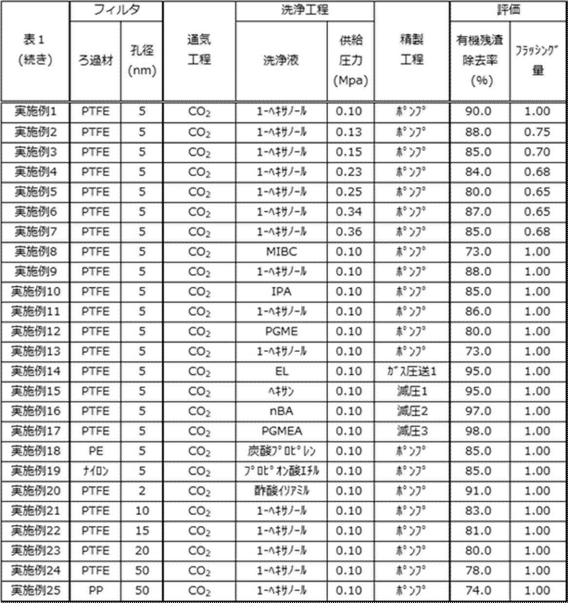
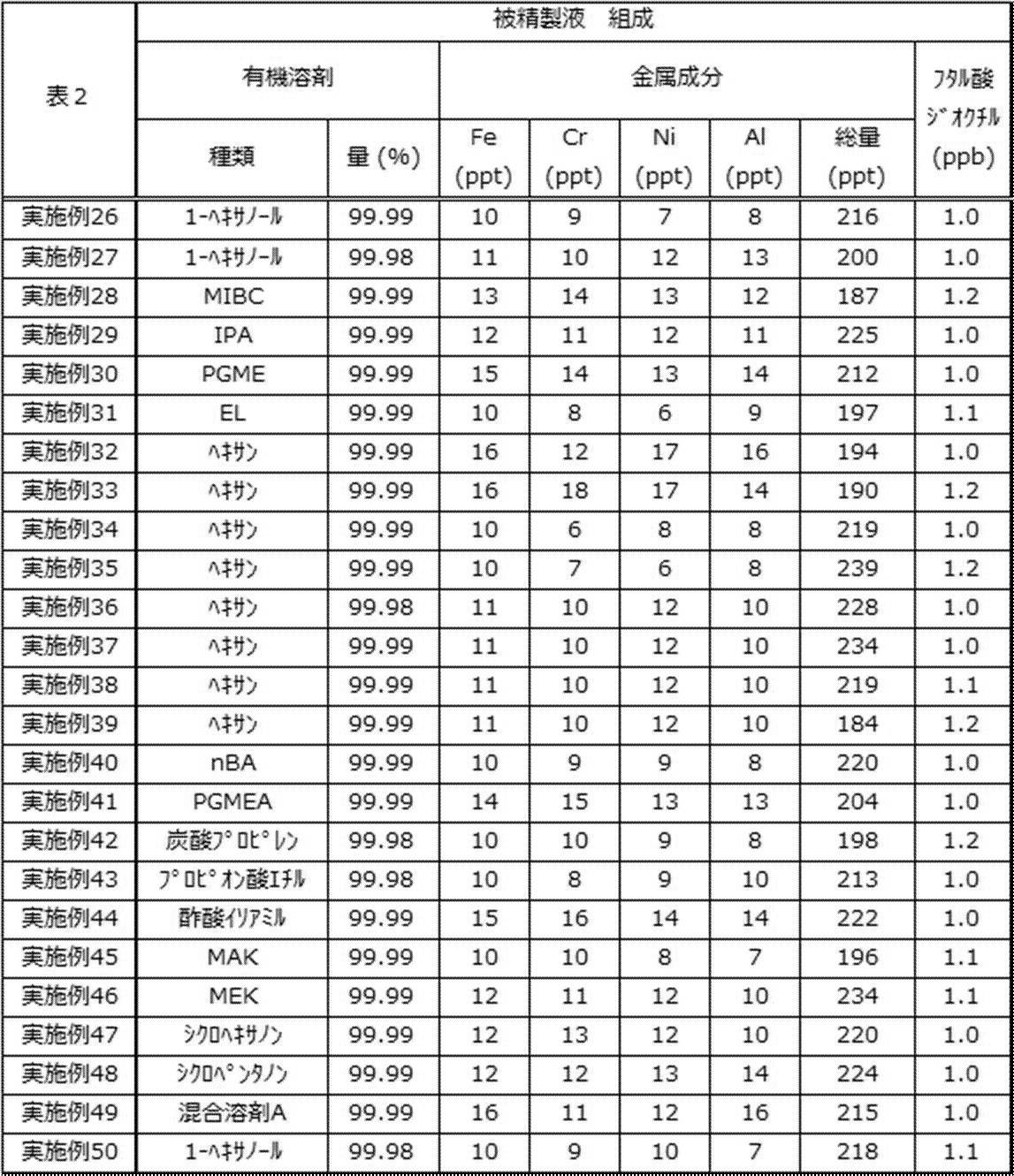

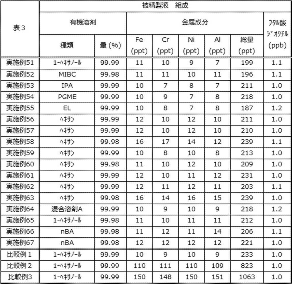
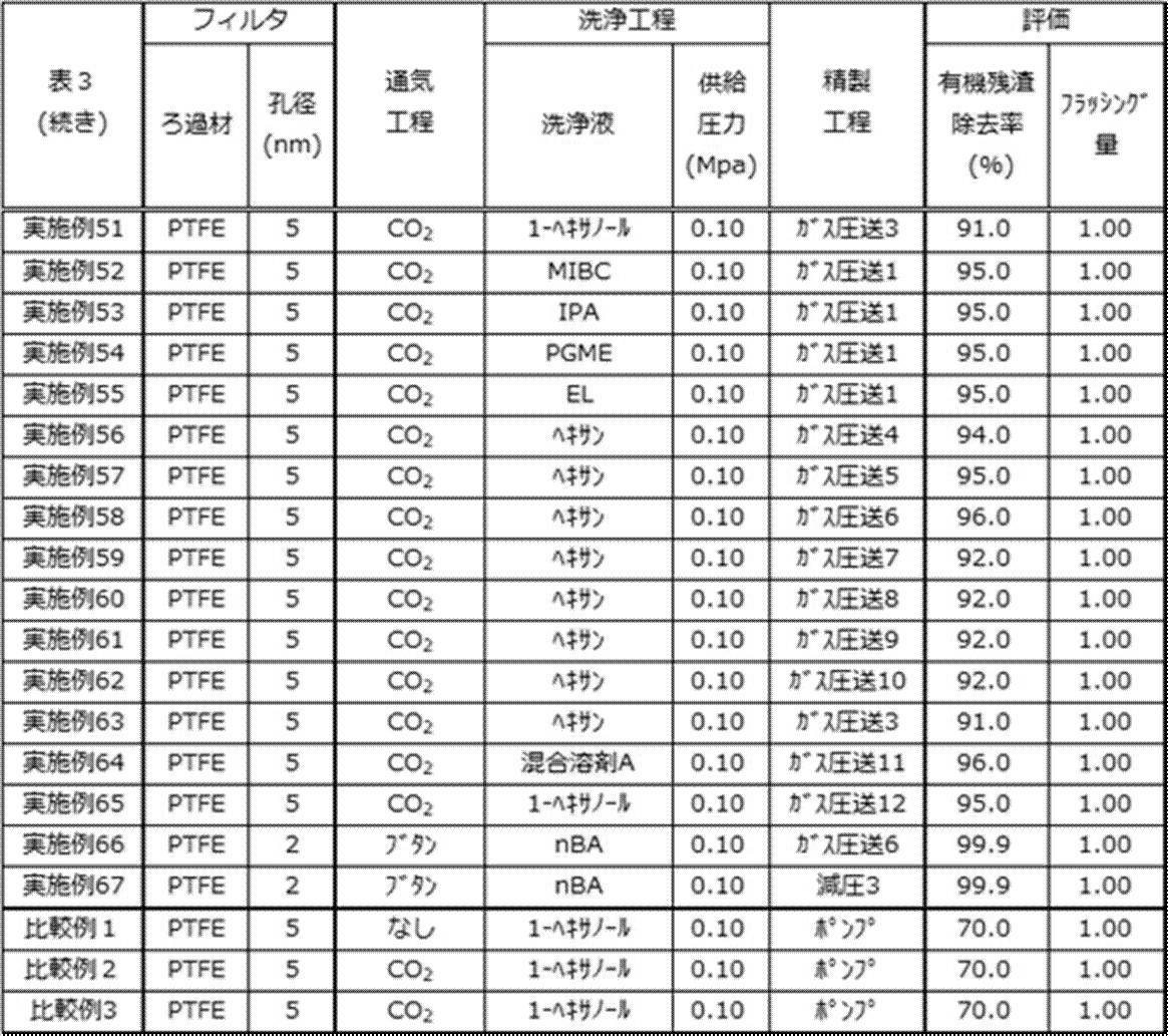
表1に示すとおり、実施例1~67の薬液の精製方法は、優れた有機不純物粒子除去性能を有していた。一方、比較例1~3の薬液の精製方法は、所望の効果を有していなかった。
また、有機溶剤の含有量が被精製液の全質量に対して98質量%以上である場合、有機不純物粒子除去性能がより優れることが確認され(実施例7と実施例8との比較参照)、有機溶剤の含有量が被精製液の全質量に対して99質量%以上である場合、有機不純物粒子除去性能が更に優れることが確認され(実施例6と実施例7との比較参照)、有機溶剤の含有量が被精製液の全質量に対して99.9質量%以上である場合、有機不純物粒子除去性能が特に優れることが確認された(実施例1と実施例6との比較参照)。
特定金属成分の含有量がいずれも、被精製液の全質量に対して50質量ppt以下である場合、有機不純物粒子除去性能がより優れることが確認され(実施例3と実施例4との比較参照)、特定金属成分の含有量がいずれも、被精製液の全質量に対して10質量ppt以下である場合、有機不純物粒子除去性能が更に優れることが確認された(実施例1と実施例2との比較参照)。
DOPの含有量が被精製液の全質量に対して10質量ppb以下である場合、有機不純物粒子除去性能がより優れることが確認され(実施例12と実施例13との比較参照)、DOPの含有量が被精製液の全質量に対して5質量ppb以下である場合、有機不純物粒子除去性能が更に優れることが確認され(実施例10と実施例11との比較参照)、DOPの含有量が被精製液の全質量に対して1質量ppb以下である場合、有機不純物粒子除去性能が特に優れることが確認された(実施例1と実施例9との比較参照)。
フィルタを構成する材料がPTFEである場合、有機不純物粒子除去性能がより優れることが確認された(実施例1と実施例18及び19との比較、実施例24と実施例25との比較を参照)
フィルタの孔径が20nm以下である場合、有機不純物粒子除去性能がより優れることが確認され(実施例22と実施例23との比較参照)、フィルタの孔径が5nm以下である場合、有機不純物粒子除去性能が更に優れることが確認され(実施例1と実施例21との比較参照)、フィルタの孔径が2nm以下である場合、有機不純物粒子除去性能が特に優れることが確認された(実施例20と実施例1との比較参照)。
フィルタの孔径が20nm以下である場合、有機不純物粒子除去性能がより優れることが確認され(実施例22と実施例23との比較参照)、フィルタの孔径が5nm以下である場合、有機不純物粒子除去性能が更に優れることが確認され(実施例1と実施例21との比較参照)、フィルタの孔径が2nm以下である場合、有機不純物粒子除去性能が特に優れることが確認された(実施例20と実施例1との比較参照)。
精製工程において、圧送用ガスを貯蔵容器の内部に導入することにより被精製液を移送する場合、圧送用ガスが、二酸化炭素、エタン、プロパン、ブタン、ブタン及びプロパンの体積比1:1での混合ガス、又は、窒素であると、有機不純物粒子除去性能がより優れることが確認された(実施例14及び50~65の比較参照)。
精製工程において、上記減圧処理により被精製液を移送する場合、減圧する管路内部の圧力が50Pa以下であると、有機不純物粒子除去性能がより優れることが確認され(実施例16と実施例15との比較参照)、減圧する管路内部の圧力が0.1Pa以下であると、有機不純物粒子除去性能が更に優れることが確認された(実施例17と実施例16との比較参照)。
精製工程において、上記減圧処理により被精製液を移送する場合、減圧する管路内部の圧力が50Pa以下であると、有機不純物粒子除去性能がより優れることが確認され(実施例16と実施例15との比較参照)、減圧する管路内部の圧力が0.1Pa以下であると、有機不純物粒子除去性能が更に優れることが確認された(実施例17と実施例16との比較参照)。
洗浄工程において、管路内部のフィルタよりも上流側の圧力が0.15~0.34MPaである場合、洗浄液による洗浄効率がより優れることが確認され(実施例3と実施例2との比較参照)、管路内部のフィルタよりも上流側の圧力が0.10~0.34MPaである場合、洗浄液による洗浄効率が更に優れることが確認された(実施例5と実施例4との比較、実施例6と実施例7との比較参照)。
10 精製装置
11 貯蔵容器
12 フィルタユニット
13 充填装置
14 管路
20 フィルタカートリッジ
21 フィルタ
22 コア
23 スリーブ
24 キャップ
25 流出口
31 本体
32 蓋
33 流入口
34 流出口
35 第1内部管路
36 第2内部管路
11 貯蔵容器
12 フィルタユニット
13 充填装置
14 管路
20 フィルタカートリッジ
21 フィルタ
22 コア
23 スリーブ
24 キャップ
25 流出口
31 本体
32 蓋
33 流入口
34 流出口
35 第1内部管路
36 第2内部管路
Claims (26)
- 管路と、前記管路に配置されるフィルタとを備える精製装置を用いて、有機溶剤を含有する薬液を精製する、薬液の精製方法であって、
前記管路にガスを供給して、前記フィルタに前記ガスを通過させる通気工程と、
前記ガスを通過させたフィルタを用いて前記薬液をろ過する精製工程と、を有し、
前記薬液における、Fe成分、Cr成分、Ni成分及びAl成分のそれぞれの含有量が、前記薬液の全質量に対していずれも100質量ppt以下である、
薬液の精製方法。 - 前記Fe成分、前記Cr成分、前記Ni成分及び前記Al成分のそれぞれの含有量が、前記薬液の全質量に対していずれも50質量ppt以下である、請求項1に記載の薬液の精製方法。
- 前記Fe成分、前記Cr成分、前記Ni成分及び前記Al成分のそれぞれの含有量が、前記薬液の全質量に対していずれも10質量ppt以下である、請求項1に記載の薬液の精製方法。
- 前記ガスが、非極性有機化合物のガスである、請求項1~3のいずれか1項に記載の薬液の精製方法。
- 前記ガスが、二酸化炭素及びアンモニアからなる群より選択される少なくとも1つを含む、請求項1~3のいずれか1項に記載の薬液の精製方法。
- 前記精製装置が、前記フィルタに送出される前記薬液を貯留する容器を更に備え、
前記精製工程において、前記容器の内部に圧送用ガスを導入することにより、前記薬液を送出し、前記薬液を前記フィルタに通過させる、請求項1~5のいずれか1項に記載の薬液の精製方法。 - 前記圧送用ガスが、非極性有機化合物のガスである、請求項6に記載の薬液の精製方法。
- 前記圧送用ガスが、二酸化炭素及びアンモニアからなる群より選択される少なくとも1つを含む、請求項6に記載の薬液の精製方法。
- 前記精製工程において、前記管路の内部のうち、前記フィルタよりも下流側の少なくとも一部を減圧する減圧処理により、前記薬液を前記フィルタに通過させる、請求項1~5のいずれか1項に記載の薬液の精製方法。
- 前記減圧処理により前記管路の内部の少なくとも一部の圧力を100Pa以下に減圧した後、前記フィルタに前記薬液を通過させる、請求項9に記載の薬液の精製方法。
- 前記減圧処理により前記管路の内部の少なくとも一部の圧力を0.1Pa以下に減圧した後、前記フィルタに前記薬液を通過させる、請求項9又は10に記載の薬液の精製方法。
- 前記薬液における有機溶剤の含有量が、前記薬液の全質量に対して98質量%以上である、請求項1~11のいずれか1項に記載の薬液の精製方法。
- 前記薬液中における有機溶剤の含有量が、前記薬液の全質量に対して99質量%以上である、請求項1~12のいずれか1項に記載の薬液の精製方法。
- 前記有機溶剤が、プロピレングリコールモノメチルエーテル、プロピレングリコールモノエチルエーテル、プロピレングリコールモノプロピルエーテル、プロピレングリコールモノメチルエーテルアセテート、乳酸エチル、メトキシプロピオン酸メチル、プロピオン酸エチル、シクロペンタノン、シクロヘキサノン、γ-ブチロラクトン、ジイソアミルエーテル、酢酸ブチル、酢酸イソアミル、イソプロパノール、4-メチル-2-ペンタノール、1-ヘキサノール、ジメチルスルホキシド、n-メチル-2-ピロリドン、ジエチレングリコール、エチレングリコール、ジプロピレングリコール、プロピレングリコール、炭酸エチレン、炭酸プロピレン、スルホラン、シクロヘプタノン、2-ヘプタノン、メチルエチルケトン、ヘキサン、及び、これらの組合せからなる群から選択される少なくとも1種である、請求項1~13のいずれか1項に記載の薬液の精製方法。
- 前記薬液におけるフタル酸ジオクチルの含有量が、前記薬液の全質量に対して10質量ppb以下である、請求項1~14のいずれか1項に記載の薬液の精製方法。
- 前記薬液におけるフタル酸ジオクチルの含有量が、前記薬液の全質量に対して5質量ppb以下である、請求項1~15のいずれか1項に記載の薬液の精製方法。
- 前記薬液におけるフタル酸ジオクチルの含有量が、前記薬液の全質量に対して1質量ppb以下である、請求項1~16のいずれか1項に記載の薬液の精製方法。
- 前記フィルタを構成する材料が、ポリエチレン、ポリプロピレン、ポリアミド及びフッ素樹脂からなる群より選択される少なくとも1つからなる、請求項1~17のいずれか1項に記載の薬液の精製方法。
- 前記フィルタの孔径が5nm以下である、請求項1~18のいずれか1項に記載の薬液の精製方法。
- 前記フィルタの孔径が2nm以下である、請求項1~19のいずれか1項に記載の薬液の精製方法。
- 前記通気工程の後であって、前記精製工程の前に、洗浄液を前記フィルタに通過させて前記フィルタを洗浄する洗浄工程を更に有する、請求項1~20のいずれか1項に記載の薬液の精製方法。
- 前記洗浄工程において、前記管路内部の前記フィルタよりも上流側の圧力が、0.10~0.34MPaである、請求項21に記載の薬液の精製方法。
- 前記洗浄工程において、前記管路内部の前記フィルタよりも上流側の圧力が、0.15~0.34MPaである、請求項21又は22に記載の薬液の精製方法。
- 前記洗浄工程において、前記管路内部の前記フィルタよりも上流側の圧力が、0.25~0.34MPaである、請求項21~23のいずれか1項に記載の薬液の精製方法。
- 請求項1~24のいずれか1項に記載の薬液の精製方法を有する薬液の製造方法。
- 請求項25に記載の薬液の製造方法により製造された薬液。
Priority Applications (1)
| Application Number | Priority Date | Filing Date | Title |
|---|---|---|---|
| JP2022505882A JP7390470B2 (ja) | 2020-03-12 | 2021-02-18 | 薬液の精製方法、薬液の製造方法、薬液 |
Applications Claiming Priority (2)
| Application Number | Priority Date | Filing Date | Title |
|---|---|---|---|
| JP2020-042604 | 2020-03-12 | ||
| JP2020042604 | 2020-03-12 |
Publications (1)
| Publication Number | Publication Date |
|---|---|
| WO2021182064A1 true WO2021182064A1 (ja) | 2021-09-16 |
Family
ID=77671670
Family Applications (1)
| Application Number | Title | Priority Date | Filing Date |
|---|---|---|---|
| PCT/JP2021/006184 Ceased WO2021182064A1 (ja) | 2020-03-12 | 2021-02-18 | 薬液の精製方法、薬液の製造方法、薬液 |
Country Status (2)
| Country | Link |
|---|---|
| JP (1) | JP7390470B2 (ja) |
| WO (1) | WO2021182064A1 (ja) |
Cited By (1)
| Publication number | Priority date | Publication date | Assignee | Title |
|---|---|---|---|---|
| WO2025063059A1 (ja) * | 2023-09-21 | 2025-03-27 | 株式会社Screenホールディングス | 基板処理装置 |
Citations (6)
| Publication number | Priority date | Publication date | Assignee | Title |
|---|---|---|---|---|
| JP2003251154A (ja) * | 2002-02-28 | 2003-09-09 | Nitto Denko Corp | ベッセル、膜モジュールおよびその運転方法 |
| JP2013061426A (ja) * | 2011-09-12 | 2013-04-04 | Nomura Micro Sci Co Ltd | フォトレジスト膜形成用樹脂溶液の不純物除去方法、不純物除去用濾過部材及び不純物除去用濾過装置 |
| JP2016179417A (ja) * | 2015-03-23 | 2016-10-13 | 日本碍子株式会社 | 分離方法及び分離装置 |
| WO2018043697A1 (ja) * | 2016-09-02 | 2018-03-08 | 富士フイルム株式会社 | 有機溶剤の精製方法および有機溶剤の精製装置 |
| WO2018180735A1 (ja) * | 2017-03-31 | 2018-10-04 | 富士フイルム株式会社 | 薬液の精製方法、薬液の製造方法、及び、薬液 |
| JP2019150823A (ja) * | 2017-03-31 | 2019-09-12 | 日本碍子株式会社 | ゼオライト膜複合体、および、ゼオライト膜複合体の製造方法 |
Family Cites Families (4)
| Publication number | Priority date | Publication date | Assignee | Title |
|---|---|---|---|---|
| JP2015147187A (ja) | 2014-02-07 | 2015-08-20 | 東レ株式会社 | ナノ材料の分離方法 |
| JP7084683B2 (ja) | 2015-02-23 | 2022-06-15 | 東京応化工業株式会社 | 液体の精製方法、薬液又は洗浄液の製造方法、フィルターメディア、及び、フィルターデバイス |
| WO2018062471A1 (ja) | 2016-09-30 | 2018-04-05 | 富士フイルム株式会社 | パターン形成方法、電子デバイスの製造方法、キット |
| JP6818037B2 (ja) | 2016-09-30 | 2021-01-20 | 富士フイルム株式会社 | 半導体チップの製造方法、キット |
-
2021
- 2021-02-18 WO PCT/JP2021/006184 patent/WO2021182064A1/ja not_active Ceased
- 2021-02-18 JP JP2022505882A patent/JP7390470B2/ja active Active
Patent Citations (6)
| Publication number | Priority date | Publication date | Assignee | Title |
|---|---|---|---|---|
| JP2003251154A (ja) * | 2002-02-28 | 2003-09-09 | Nitto Denko Corp | ベッセル、膜モジュールおよびその運転方法 |
| JP2013061426A (ja) * | 2011-09-12 | 2013-04-04 | Nomura Micro Sci Co Ltd | フォトレジスト膜形成用樹脂溶液の不純物除去方法、不純物除去用濾過部材及び不純物除去用濾過装置 |
| JP2016179417A (ja) * | 2015-03-23 | 2016-10-13 | 日本碍子株式会社 | 分離方法及び分離装置 |
| WO2018043697A1 (ja) * | 2016-09-02 | 2018-03-08 | 富士フイルム株式会社 | 有機溶剤の精製方法および有機溶剤の精製装置 |
| WO2018180735A1 (ja) * | 2017-03-31 | 2018-10-04 | 富士フイルム株式会社 | 薬液の精製方法、薬液の製造方法、及び、薬液 |
| JP2019150823A (ja) * | 2017-03-31 | 2019-09-12 | 日本碍子株式会社 | ゼオライト膜複合体、および、ゼオライト膜複合体の製造方法 |
Cited By (1)
| Publication number | Priority date | Publication date | Assignee | Title |
|---|---|---|---|---|
| WO2025063059A1 (ja) * | 2023-09-21 | 2025-03-27 | 株式会社Screenホールディングス | 基板処理装置 |
Also Published As
| Publication number | Publication date |
|---|---|
| JP7390470B2 (ja) | 2023-12-01 |
| JPWO2021182064A1 (ja) | 2021-09-16 |
Similar Documents
| Publication | Publication Date | Title |
|---|---|---|
| JP7282862B2 (ja) | 薬液の精製方法 | |
| JP6943888B2 (ja) | 薬液の製造方法、及び、薬液の製造装置 | |
| JP6794462B2 (ja) | 薬液、薬液収容体、薬液の製造方法、及び、薬液収容体の製造方法 | |
| US12311294B2 (en) | Chemical liquid purification method and chemical liquid | |
| JP7390470B2 (ja) | 薬液の精製方法、薬液の製造方法、薬液 | |
| JP2022176197A (ja) | 薬液、薬液収容体、キット、半導体チップの製造方法 | |
| JP7029459B2 (ja) | 薬液収容体 | |
| JP2025038058A (ja) | 薬液の供給方法、パターン形成方法 | |
| JP7629083B2 (ja) | 薬液、薬液収容体 | |
| TWI754080B (zh) | 構件、容器、藥液收容體、藥液的純化裝置、製造槽 | |
| KR102519818B1 (ko) | 약액, 약액 수용체 | |
| JPWO2020040003A1 (ja) | 薬液、薬液収容体 |
Legal Events
| Date | Code | Title | Description |
|---|---|---|---|
| 121 | Ep: the epo has been informed by wipo that ep was designated in this application |
Ref document number: 21768714 Country of ref document: EP Kind code of ref document: A1 |
|
| ENP | Entry into the national phase |
Ref document number: 2022505882 Country of ref document: JP Kind code of ref document: A |
|
| NENP | Non-entry into the national phase |
Ref country code: DE |
|
| 122 | Ep: pct application non-entry in european phase |
Ref document number: 21768714 Country of ref document: EP Kind code of ref document: A1 |