WO2021182059A1 - 元素分析装置 - Google Patents
元素分析装置 Download PDFInfo
- Publication number
- WO2021182059A1 WO2021182059A1 PCT/JP2021/006093 JP2021006093W WO2021182059A1 WO 2021182059 A1 WO2021182059 A1 WO 2021182059A1 JP 2021006093 W JP2021006093 W JP 2021006093W WO 2021182059 A1 WO2021182059 A1 WO 2021182059A1
- Authority
- WO
- WIPO (PCT)
- Prior art keywords
- flow path
- dust
- electrode
- cleaning gas
- furnace
- Prior art date
- Legal status (The legal status is an assumption and is not a legal conclusion. Google has not performed a legal analysis and makes no representation as to the accuracy of the status listed.)
- Ceased
Links
Images


Classifications
-
- G—PHYSICS
- G01—MEASURING; TESTING
- G01N—INVESTIGATING OR ANALYSING MATERIALS BY DETERMINING THEIR CHEMICAL OR PHYSICAL PROPERTIES
- G01N1/00—Sampling; Preparing specimens for investigation
- G01N1/02—Devices for withdrawing samples
- G01N1/22—Devices for withdrawing samples in the gaseous state
- G01N1/2202—Devices for withdrawing samples in the gaseous state involving separation of sample components during sampling
- G01N1/2205—Devices for withdrawing samples in the gaseous state involving separation of sample components during sampling with filters
-
- G—PHYSICS
- G01—MEASURING; TESTING
- G01N—INVESTIGATING OR ANALYSING MATERIALS BY DETERMINING THEIR CHEMICAL OR PHYSICAL PROPERTIES
- G01N25/00—Investigating or analyzing materials by the use of thermal means
- G01N25/20—Investigating or analyzing materials by the use of thermal means by investigating the development of heat, i.e. calorimetry, e.g. by measuring specific heat, by measuring thermal conductivity
- G01N25/22—Investigating or analyzing materials by the use of thermal means by investigating the development of heat, i.e. calorimetry, e.g. by measuring specific heat, by measuring thermal conductivity on combustion or catalytic oxidation, e.g. of components of gas mixtures
-
- F—MECHANICAL ENGINEERING; LIGHTING; HEATING; WEAPONS; BLASTING
- F27—FURNACES; KILNS; OVENS; RETORTS
- F27B—FURNACES, KILNS, OVENS OR RETORTS IN GENERAL; OPEN SINTERING OR LIKE APPARATUS
- F27B14/00—Crucible or pot furnaces
- F27B14/06—Crucible or pot furnaces heated electrically, e.g. induction crucible furnaces with or without any other source of heat
-
- F—MECHANICAL ENGINEERING; LIGHTING; HEATING; WEAPONS; BLASTING
- F27—FURNACES; KILNS; OVENS; RETORTS
- F27B—FURNACES, KILNS, OVENS OR RETORTS IN GENERAL; OPEN SINTERING OR LIKE APPARATUS
- F27B14/00—Crucible or pot furnaces
- F27B14/08—Details specially adapted for crucible or pot furnaces
- F27B14/20—Arrangement of controlling, monitoring, alarm or like devices
-
- F—MECHANICAL ENGINEERING; LIGHTING; HEATING; WEAPONS; BLASTING
- F27—FURNACES; KILNS; OVENS; RETORTS
- F27B—FURNACES, KILNS, OVENS OR RETORTS IN GENERAL; OPEN SINTERING OR LIKE APPARATUS
- F27B17/00—Furnaces of a kind not covered by any of groups F27B1/00 - F27B15/00
- F27B17/02—Furnaces of a kind not covered by any of groups F27B1/00 - F27B15/00 specially designed for laboratory use
-
- F—MECHANICAL ENGINEERING; LIGHTING; HEATING; WEAPONS; BLASTING
- F27—FURNACES; KILNS; OVENS; RETORTS
- F27D—DETAILS OR ACCESSORIES OF FURNACES, KILNS, OVENS OR RETORTS, IN SO FAR AS THEY ARE OF KINDS OCCURRING IN MORE THAN ONE KIND OF FURNACE
- F27D21/00—Arrangement of monitoring devices; Arrangement of safety devices
-
- G—PHYSICS
- G01—MEASURING; TESTING
- G01N—INVESTIGATING OR ANALYSING MATERIALS BY DETERMINING THEIR CHEMICAL OR PHYSICAL PROPERTIES
- G01N1/00—Sampling; Preparing specimens for investigation
- G01N1/02—Devices for withdrawing samples
- G01N1/10—Devices for withdrawing samples in the liquid or fluent state
- G01N1/14—Suction devices, e.g. pumps; Ejector devices
-
- G—PHYSICS
- G01—MEASURING; TESTING
- G01N—INVESTIGATING OR ANALYSING MATERIALS BY DETERMINING THEIR CHEMICAL OR PHYSICAL PROPERTIES
- G01N1/00—Sampling; Preparing specimens for investigation
- G01N1/02—Devices for withdrawing samples
- G01N1/10—Devices for withdrawing samples in the liquid or fluent state
- G01N1/20—Devices for withdrawing samples in the liquid or fluent state for flowing or falling materials
- G01N1/2035—Devices for withdrawing samples in the liquid or fluent state for flowing or falling materials by deviating part of a fluid stream, e.g. by drawing-off or tapping
-
- G—PHYSICS
- G01—MEASURING; TESTING
- G01N—INVESTIGATING OR ANALYSING MATERIALS BY DETERMINING THEIR CHEMICAL OR PHYSICAL PROPERTIES
- G01N1/00—Sampling; Preparing specimens for investigation
- G01N1/02—Devices for withdrawing samples
- G01N1/22—Devices for withdrawing samples in the gaseous state
- G01N1/2226—Sampling from a closed space, e.g. food package, head space
-
- G—PHYSICS
- G01—MEASURING; TESTING
- G01N—INVESTIGATING OR ANALYSING MATERIALS BY DETERMINING THEIR CHEMICAL OR PHYSICAL PROPERTIES
- G01N1/00—Sampling; Preparing specimens for investigation
- G01N1/02—Devices for withdrawing samples
- G01N1/22—Devices for withdrawing samples in the gaseous state
- G01N1/2247—Sampling from a flowing stream of gas
-
- G—PHYSICS
- G01—MEASURING; TESTING
- G01N—INVESTIGATING OR ANALYSING MATERIALS BY DETERMINING THEIR CHEMICAL OR PHYSICAL PROPERTIES
- G01N1/00—Sampling; Preparing specimens for investigation
- G01N1/28—Preparing specimens for investigation including physical details of (bio-)chemical methods covered elsewhere, e.g. G01N33/50, C12Q
- G01N1/34—Purifying; Cleaning
-
- G—PHYSICS
- G01—MEASURING; TESTING
- G01N—INVESTIGATING OR ANALYSING MATERIALS BY DETERMINING THEIR CHEMICAL OR PHYSICAL PROPERTIES
- G01N31/00—Investigating or analysing non-biological materials by the use of the chemical methods specified in the subgroup; Apparatus specially adapted for such methods
- G01N31/12—Investigating or analysing non-biological materials by the use of the chemical methods specified in the subgroup; Apparatus specially adapted for such methods using combustion
-
- G—PHYSICS
- G01—MEASURING; TESTING
- G01N—INVESTIGATING OR ANALYSING MATERIALS BY DETERMINING THEIR CHEMICAL OR PHYSICAL PROPERTIES
- G01N1/00—Sampling; Preparing specimens for investigation
- G01N1/28—Preparing specimens for investigation including physical details of (bio-)chemical methods covered elsewhere, e.g. G01N33/50, C12Q
- G01N1/44—Sample treatment involving radiation, e.g. heat
-
- G—PHYSICS
- G01—MEASURING; TESTING
- G01N—INVESTIGATING OR ANALYSING MATERIALS BY DETERMINING THEIR CHEMICAL OR PHYSICAL PROPERTIES
- G01N1/00—Sampling; Preparing specimens for investigation
- G01N1/02—Devices for withdrawing samples
- G01N1/10—Devices for withdrawing samples in the liquid or fluent state
- G01N1/14—Suction devices, e.g. pumps; Ejector devices
- G01N2001/1418—Depression, aspiration
- G01N2001/1436—Ejector
-
- G—PHYSICS
- G01—MEASURING; TESTING
- G01N—INVESTIGATING OR ANALYSING MATERIALS BY DETERMINING THEIR CHEMICAL OR PHYSICAL PROPERTIES
- G01N1/00—Sampling; Preparing specimens for investigation
- G01N1/02—Devices for withdrawing samples
- G01N1/10—Devices for withdrawing samples in the liquid or fluent state
- G01N1/20—Devices for withdrawing samples in the liquid or fluent state for flowing or falling materials
- G01N1/2035—Devices for withdrawing samples in the liquid or fluent state for flowing or falling materials by deviating part of a fluid stream, e.g. by drawing-off or tapping
- G01N2001/205—Devices for withdrawing samples in the liquid or fluent state for flowing or falling materials by deviating part of a fluid stream, e.g. by drawing-off or tapping using a valve
-
- G—PHYSICS
- G01—MEASURING; TESTING
- G01N—INVESTIGATING OR ANALYSING MATERIALS BY DETERMINING THEIR CHEMICAL OR PHYSICAL PROPERTIES
- G01N1/00—Sampling; Preparing specimens for investigation
- G01N1/02—Devices for withdrawing samples
- G01N1/22—Devices for withdrawing samples in the gaseous state
- G01N1/2226—Sampling from a closed space, e.g. food package, head space
- G01N2001/2235—Sampling from a closed space, e.g. food package, head space over a melt, e.g. furnace
-
- G—PHYSICS
- G01—MEASURING; TESTING
- G01N—INVESTIGATING OR ANALYSING MATERIALS BY DETERMINING THEIR CHEMICAL OR PHYSICAL PROPERTIES
- G01N1/00—Sampling; Preparing specimens for investigation
- G01N1/02—Devices for withdrawing samples
- G01N1/22—Devices for withdrawing samples in the gaseous state
- G01N1/2226—Sampling from a closed space, e.g. food package, head space
- G01N2001/2238—Sampling from a closed space, e.g. food package, head space the gas being compressed or pressurized
-
- G—PHYSICS
- G01—MEASURING; TESTING
- G01N—INVESTIGATING OR ANALYSING MATERIALS BY DETERMINING THEIR CHEMICAL OR PHYSICAL PROPERTIES
- G01N1/00—Sampling; Preparing specimens for investigation
- G01N1/02—Devices for withdrawing samples
- G01N1/22—Devices for withdrawing samples in the gaseous state
- G01N1/2247—Sampling from a flowing stream of gas
- G01N2001/227—Sampling from a flowing stream of gas separating gas from solid, e.g. filter
Definitions
- the present invention relates to an elemental analyzer that analyzes elements contained in a sample based on a sample gas generated by heating the sample.
- An elemental analyzer is used to quantify elements such as nitrogen (N), hydrogen (H), and oxygen (O) contained in the sample.
- a graphite crucible containing a sample is sandwiched between a pair of electrodes in a heating furnace, and an electric current is directly passed through the crucible to heat the crucible and the sample.
- the mixed gas composed of the sample gas and the carry gas generated by heating is passed through a dust filter to filter dust such as soot.
- the concentration of various components contained in the mixed gas after being filtered is measured by an analytical mechanism consisting of NDIR (Non Dispersive Infrared: non-dispersive infrared gas analyzer), TCD (Thermal Conductivity Detector), etc. NS.
- the present invention has been made in view of the above-mentioned problems, and an object of the present invention is to provide an elemental analyzer capable of reducing the frequency of replacement of dust filters and reducing the time and effort required for maintenance by the user.
- the element analyzer includes a heating furnace in which a sample placed in a pot is heated to generate a sample gas from the sample, an introduction flow path for introducing a carrier gas into the heating furnace, and the heating furnace.
- the dust such as soot collected in the dust filter can be flushed to the heating furnace side by the cleaning gas supplied by the cleaning gas supply mechanism, and the dust filter can be regenerated.
- the frequency of maintenance such as replacement and cleaning of the dust filter can be reduced as compared with the conventional case.
- the cleaning gas is flowed from between the dust filter and the analysis mechanism in the lead-out flow path so as to flow back through the lead-out flow path, dust such as soot separated from the dust filter is sent to the analysis mechanism. Not flowing. Therefore, the analysis accuracy of the analysis mechanism can be maintained even if the dust filter is regenerated.
- the analysis mechanism is allowed to allow the cleaning gas to flow back toward the dust filter in the lead-out flow path, so that the cleaning gas does not flow to the analysis mechanism, and dust such as soot separated from the dust filter is prevented from flowing to the analysis mechanism.
- the cleaning flow path is further provided with an exhaust flow path that branches from between the dust filter and the analysis mechanism in the lead-out flow path and exhausts the mixed gas that has passed through the dust filter.
- the gas supply mechanism is provided with at least a switching valve provided at a branch point between the lead-out flow path and the branch flow path so that the cleaning gas flows in the direction opposite to the direction in which the mixed gas flows in the lead-out flow path. It may be any one provided with a flow path switching unit for switching the flow path and a cleaning gas supply unit for supplying cleaning gas to the exhaust flow path or the switching valve.
- the cleaning gas supply unit injects the cleaning gas at a predetermined pressure for cleaning.
- a first three-way valve that includes a gas supply source, a cleaning gas supply flow path that connects the supply source, and the exhaust flow path, and the flow path switching unit is the switching valve, and the exhaust gas. Examples thereof include a second three-way valve provided at a confluence of the flow path and the cleaning gas supply flow path. In such a case, the second three-way valve required to form the cleaning gas supply unit is not provided on the lead-out flow path, so that the conventional elemental analyzer is on the lead-out flow path.
- the analysis accuracy can be maintained without adding an extra valve. That is, if a valve other than the first three-way valve is added on the lead-out flow path, the number of places where the mixed gas stagnates at the time of analysis increases, and the gas escape to the analysis mechanism at the time of analysis becomes worse. This may lead to a decrease in sensitivity. Further, when the cleaning gas is sprayed onto the dust filter for backwashing, the components of the cleaning gas remain in the valve provided on the lead-out flow path, and the components of the cleaning gas are contained together with the mixed gas in the next analysis. It may be detected by the analysis mechanism and the analysis accuracy may deteriorate. With the arrangement of the second three-way valve as described above, it is possible to prevent such problems from occurring in the first place.
- the cleaning gas supply unit is used for cleaning.
- a cleaning gas supply source for injecting gas at a predetermined pressure and a cleaning gas supply flow path connected to the cleaning gas supply source are provided, and the flow path switching unit serves as the switching valve of the lead-out flow path.
- the dust filter may be a membrane filter. Any one may be provided with a filter holder for holding and holding the membrane filter in the thickness direction. Further, in such a case, when the membrane filter cannot be regenerated with the cleaning gas, the membrane filter may be simply removed from the filter holder and replaced. Therefore, the labor required for the replacement work can be reduced as compared with the conventional case.
- the filter holder may be made of resin or glass. Further, if the filter holder is formed of transparent resin or glass, the degree of dust collection such as soot in the membrane filter can be visually confirmed, so that it is easy to determine when to supply the cleaning gas. Therefore, the frequency of supplying cleaning gas can be minimized and the labor required for maintenance can be reduced.
- the dust filter is a metal filter and a filter holder to which the metal filter is welded. It suffices as long as it is provided with.
- the heating furnace is configured to be movable between a furnace closed position in which the pot is sandwiched between the first electrode and the first electrode and a furnace open position separated from the furnace closed position by a predetermined distance.
- a second electrode a drive mechanism for moving the second electrode between the furnace closed position and the furnace open position, and a dust suction flow path provided with a dust suction port that opens in the heating furnace and sucks dust.
- An ejector including a suction port connected to the heating furnace side on the dust suction flow path, a discharge port connected to the discharge side on the dust suction flow path, and a drive port to which a working fluid is supplied.
- the drive mechanism is configured so that the working fluid flows into the drive port of the ejector when the second electrode is moved from the furnace closed position to the furnace open position, the above.
- the ejector can exert a suction action.
- the dust scattered as the heating furnace is opened can be recovered from the dust suction port in the heating furnace through the dust suction flow path by the suction action of the ejector.
- the drive mechanism is a first port through which the working fluid flows in or out.
- the first port is a fluid pressure cylinder configured to be configured so that the piston rod is pulled in and the second electrode moves to the furnace open position side when the working fluid flows in from the first port.
- the working fluid may also flow into the ejector from the drive port.
- a first supply line connecting the working fluid supply source and the first port, and the first supply Any drive line that branches off from the line and is connected to the drive port may be further provided.
- the fluid pressure cylinder is used. It is provided with a second port through which the working fluid flows in or out, and when the working fluid flows in from the second port, the piston rod is pushed out and the second electrode is configured to move to the furnace closed position side. Anything is fine.
- the fluid pressure cylinder is an air cylinder.
- the working fluid may be compressed air.
- An example is one in which the dust suction flow path is formed inside, a support for supporting the second electrode is further provided, and the piston rod of the fluid pressure cylinder is connected to the support.
- the dust suction flow path may be provided with a plurality of dust suction ports that open on the surface of the support.
- a cleaning mechanism configured to move between the first electrode and the second electrode to remove dust from the first electrode or the second electrode is further provided, and the cleaning mechanism is the first electrode.
- the dust dropped from the second electrode may be configured to be recovered from the inside of the heating furnace via the dust suction flow path.
- the heating furnace is movable between the furnace closing position where the pot is sandwiched between the first electrode and the first electrode and the furnace opening position which is separated from the furnace closing position by a predetermined distance.
- a dust suction port including a configured second electrode, a drive mechanism for moving the second electrode between the furnace closed position and the furnace open position, and a dust suction port that opens in the heating furnace and sucks dust.
- An ejector including a flow path, a suction port connected to the heating furnace side on the dust suction flow path, a discharge port connected to the discharge side on the dust suction flow path, and a drive port to which a working fluid is supplied.
- the cleaning gas is supplied to the dust filter by the cleaning gas supply mechanism in the direction opposite to the direction in which the mixed gas flows during analysis, and the soot is collected. Dust can be flowed into the heating furnace. Therefore, the dust filter can be regenerated to reduce the replacement frequency, and the analysis accuracy can be maintained by preventing dust such as soot peeling from the dust filter during regeneration from reaching the analysis mechanism.
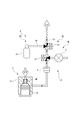
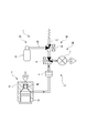
- the schematic diagram which shows the whole structure of the elemental analyzer in one Embodiment of this invention The schematic diagram which shows the structure of a heating furnace and its surroundings in the same embodiment.
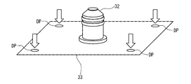
- the schematic perspective view which shows the structure around the lower electrode (second electrode) in the same embodiment.
- the schematic cross-sectional view which shows the structure of the ejector in the same embodiment.
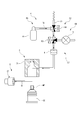
- the schematic diagram which shows the state at the time of exhausting which expanded the periphery of the cleaning gas supply mechanism in the same embodiment.
- FIG. 6 is an enlarged schematic view of the periphery of the cleaning gas supply mechanism according to another embodiment of the present invention.
- the schematic diagram which shows the structure of a heating furnace and its surroundings in still another embodiment of this invention.
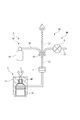
- FIG. 1 shows an outline of the elemental analyzer 100 of the present embodiment.
- the elemental analyzer 100 heats and dissolves, for example, a metal sample, a ceramics sample, or the like (hereinafter, simply referred to as a sample) housed in the graphite pot MP, and analyzes the sample gas generated at that time in the sample. It measures the amount of elements contained.
- O oxygen
- H hydrogen
- N nitrogen
- the elemental analyzer 100 includes a heating furnace 3 in which a sample housed in a crucible MP is heated, an introduction flow path L1 for introducing a carrier gas into the heating furnace 3, and an introduction flow path L1. It is provided with a lead-out flow path L2 from which a mixed gas of a carrier gas and a sample gas is derived from the heating furnace 3. More specifically, the elemental analyzer 100 controls the heating furnace 3, each device provided in the introduction flow path L1 or the lead-out flow path L2, control of each device, and control of arithmetic processing such as measured concentration. It is composed of a calculation mechanism COM.
- the control calculation mechanism COM is, for example, a so-called computer equipped with a CPU, a memory, an A / D converter, a D / A converter, and various input / output means, and a program stored in the memory is executed and various devices cooperate with each other. Therefore, the functions as the measurement value calculation unit C1 and the mode setter C2, which will be described later, are exhibited. Further, the control calculation mechanism COM displays the concentrations of various elements contained in the sample based on the outputs of, for example, CO detection unit 5, CO 2 detection unit 7, H 2 O detection unit 8, and N 2 detection unit 11, which will be described later. It also functions as a display unit (not shown).
- a gas cylinder which is a carrier gas supply source 1, is connected to the base end of the introduction flow path L1.
- He helium
- a purifier 2 is provided on the introduction flow path L1 to remove a minute amount of hydrocarbons contained in the carrier gas to increase the purity of the carrier gas.
- the refiner 2 is made of a material that physically adsorbs hydrocarbons contained in the carrier gas and does not substantially adsorb the carrier gas itself.
- the material forming the refiner 2 does not chemically react with the carrier gas or hydrocarbon. That is, this refiner 2 is also used in, for example, a gas chromatograph, and for example, a zeolite-based molecular sieve can be used as a material for forming the refiner 2.
- the material for forming the refiner 2 may be silica gel, activated carbon, ascarite or the like.
- the heating furnace 3 is configured to sandwich the graphite crucible MP containing the sample between the first electrode and the second electrode, which are a pair of electrodes, and directly apply an electric current to the crucible MP to heat the crucible MP and the sample. ing.
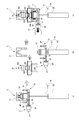
- the heating furnace 3 has an upper electrode 31 which is a cylindrical first electrode in which an internal space is formed and an upper electrode 31 which is inserted into the internal space to provide a crucible MP. It is provided with a lower electrode 32 which is a columnar second electrode sandwiched between the two.
- the upper electrode 31 is formed with through holes in the vertical direction for supplying the carrier gas supplied from the introduction flow path L1 to the internal space. Further, the mixed gas of the sample gas and the carrier gas generated from the sample flows out into the lead-out flow path L2 through the through hole formed on the side surface of the upper electrode 31.
- the lower electrode 32 is configured to move forward and backward in the vertical direction by an air cylinder 34 which is a linear fluid pressure cylinder. That is, specifically, when the sample in the crucible MP is heated, the lower electrode 32 is moved upward by the air cylinder 34 and inserted into the internal space of the upper electrode 31. In this state, the crucible MP is sandwiched between the upper electrode 31 and the lower electrode 32. Further, the lower electrode 32 airtightly closes the lower opening of the upper electrode 31 by a seal portion provided on the side surface so as to project toward the outer peripheral side. As a result, the mixed gas in which the sample gas and the carrier gas generated by heating the sample are mixed flows out from the side surface side of the upper electrode 31 to the lead-out flow path L2.
- an air cylinder 34 which is a linear fluid pressure cylinder. That is, specifically, when the sample in the crucible MP is heated, the lower electrode 32 is moved upward by the air cylinder 34 and inserted into the internal space of the upper electrode 31. In this state, the crucible MP is
- the lower electrode 32 has a furnace closed position for sandwiching the crucible with the upper electrode 31 as shown in FIG. 2 (a) and a furnace separated from the furnace closed position by a predetermined distance as shown in FIG. 2 (b). It is configured to be movable between and from the open position.
- the furnace closing position is arranged below the furnace opening position.
- a door (not shown) is closed in the heating furnace 3 so that the sample gas generated inside does not leak to the outside.
- a door (not shown) is opened for replacement of the crucible MP or for cleaning and maintenance of the inside of the heating furnace 3. That is, when cleaning the dust filter 4 or exchanging the sample, which will be described later, the lower electrode 32 is moved downward by the air cylinder 34 and is arranged outside the internal space of the upper electrode 31.
- the space inside the heating furnace 3 is in a state of communicating with the suction source P such as a vacuum cleaner.
- the suction source P such as a vacuum cleaner.
- the lower electrode 32 is supported by a support 33 having a bottom surface formed in a substantially flat rectangular parallelepiped shape.
- the piston rod 35 of the air cylinder 34 is connected to the outside of the support 33, and by moving the support 33 in the vertical direction by the air cylinder 34, the lower electrode 32 is placed between the furnace closed position and the furnace open position. Move with.
- a first port SP1 and a second port SP2 into which compressed air, which is a working fluid, flows in or out, are opened on the side surface of the cylinder 36.
- compressed air flows into the first port SP1
- the piston rod 35 is drawn into the cylinder 36.
- compressed air flows into the second port SP2
- the piston rod 35 is pushed out of the cylinder 36. That is, in the cylinder 36, the first chamber communicating with the first port SP1 and the second chamber communicating with the second port SP2 are separated by the piston rod 35, and the first chamber and the second chamber are separated by the inflow and outflow of compressed air.
- the compressed air supply source and the first port SP1 are connected by the first supply line SL1, and the supply source and the second port SP2 are connected by the second supply line SL2. There is. Whether the compressed air is supplied from the supply source to the first port SP1 or the second port SP2, and the amount of the compressed air to be supplied are controlled by the compressed air control mechanism provided in the supply source.
- the compressed air control mechanism is configured to perform a predetermined operation in response to, for example, a furnace opening command of the heating furnace 3 input from the mode setter C2 or a furnace closing command.
- a plurality of dust suction ports DP for sucking dust are opened on the inner surface of the furnace on the bottom surface of the support 33.
- the lower electrode 32 is supported in the center of the bottom surface of the support 33, and the dust suction ports DP are opened at each of the four corners.
- a dust suction flow path DL having the above-mentioned dust suction port DP is formed inside the support 33.
- the ejector 37 is provided so that the inside side of the heating furnace 3 and the suction port VP are connected in the dust suction flow path DL formed in the support 33. Further, the drive port AP of the ejector 37 and the first supply line SL1 are connected by a drive line AL branching from the first supply line SL1. That is, when the compressed air is supplied from the compressed air supply source to the first port SP1 of the air cylinder 34, the compressed air is also supplied to the drive port AP of the ejector 37 in parallel. ..
- the discharge port EP of the ejector 37 is connected to the exhaust side where, for example, a dust box is located in the dust suction flow path DL.
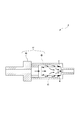
- the ejector 37 of the present embodiment will be described in detail.
- the ejector 37 has a substantially cylindrical shape, a suction port VP is formed on one end face, and a discharge port EP is formed on the other end face. Is formed.
- a drive port AP into which compressed air, which is a working fluid, flows in is formed on the side surface of the ejector 37.
- the drive port AP communicates with a nozzle (not shown) formed inside the ejector 37, and the depressurization of the air generated by the compressed air passing through the nozzle causes a gas from the suction port VP as shown in FIG. 4 (a). Is inhaled.
- the compressed air flowing in from the drive port AP and the gas sucked in from the suction port VP are discharged to the outside from the discharge port EP in a mixed state.
- the flow rate discharged from the discharge port EP is, for example, about 3 to 4 times the flow rate of the compressed air flowing in from the drive port AP. That is, the flow rate of the gas sucked from the suction port VP is about 2 to 3 times that of the compressed air flowing into the drive port AP.
- the ejector 37 generates a suction force in the suction port VP by inflowing the compressed air into the drive port AP, and sucks the dust in the heating furnace 3 from the dust suction port DP.
- the analysis mechanism AM is a CO detection unit 5, an oxidizer 6, a CO 2 detection unit 7, an H 2 O detection unit 8, a removal mechanism 9, a mass flow controller 10, and an N 2 detection unit which is a thermal conductivity analysis unit. It is composed of 11, and each device is provided side by side in this order from the upstream side in the lead-out flow path L2.
- the lead-out flow path L2 is provided with a cleaning gas supply mechanism R that supplies the cleaning gas to the dust filter 4 in the direction opposite to the direction in which the mixed gas flows.
- the cleaning gas supply mechanism R supplies the cleaning gas to the dust filter 4 via an exhaust flow path L3 that branches from between the dust filter 4 and the CO detection unit 5 located on the most upstream side in the analysis mechanism AM. It is configured as follows.
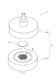
- the dust filter 4 filters out dust such as soot contained in the mixed gas and removes the dust.
- the dust filter 4 includes, for example, a membrane filter 41 made of PTFE and a filter holder 42 that sandwiches and holds the membrane filter 41 in the thickness direction.
- the filter holder 42 is configured as a flange joint in the lead-out flow path L2, and is composed of a substantially disk-shaped upstream holder 4A and a downstream holder 4B, respectively.
- a mesh-shaped sheet screen 4C is formed in the central portion of the downstream holder 4B, and a membrane filter 41 is arranged on the sheet screen 4C and is sandwiched between the sheet screen 4C and the upstream holder 4A.
- the outer peripheral portions of the upstream holder 4A and the downstream holder 4B are fastened with bolts and nuts (not shown), respectively.
- the filter holder 42 is made of a transparent resin such as acrylic, and is configured so that the state of the membrane filter 41 can be visually recognized from the outside of the filter holder 42.
- the cleaning gas supply mechanism R specifies cleaning gas to the dust filter 4 from the exhaust flow path L3 branching from between the dust filter 4 and the CO detection unit 5 in the lead-out flow path L2. It is configured to reverse-inject at a pressure above. That is, the cleaning gas supply mechanism R includes a cleaning gas supply unit RS that supplies cleaning gas to the exhaust flow path L3, and a flow path switching unit RC including two switching valves. The flow path switching unit RC is controlled by, for example, the mode setter C2, and the connection destination of each switching valve is changed according to the set mode.
- the cleaning gas supply unit RS includes, for example, a cleaning gas supply source R1 that injects an inert gas as a cleaning gas at a predetermined pressure, and a cleaning gas supply flow path R2 that connects the cleaning gas supply source R1 and the exhaust flow path L3. And have.
- the cleaning gas supply flow path R2 is provided so as to join the exhaust flow path on the upstream side of the capillary provided on the downstream end side.
- the inert gas injected from the cleaning gas supply source R1 is preferably not detected by the analysis mechanism AM, and for example, He can be used as in the carrier gas of the present embodiment.
- the flow path switching portion RC includes a first three-way valve R3 provided at a branch point between the lead-out flow path L2 and the exhaust flow path L3, and a second three-way valve R3 provided at the confluence of the exhaust flow path and the cleaning gas supply flow path R2. It is equipped with a valve R4. By switching the states of the first three-way valve R3 and the second three-way valve R4, the type of gas flowing and the direction in which the gas flows are changed as shown in FIGS. 2 to 4. That is, by switching the flow path switching unit RC, the exhaust mode shown in FIG. 5, the analysis mode shown in FIG. 6, and the cleaning mode shown in FIG. 7 are realized.
- the first three-way valve R3 communicates the lead-out flow path L2 and the exhaust flow path L3, closes the analysis mechanism AM side of the lead-out flow path L2, and the second three-way valve R4 supplies cleaning gas.
- the flow path R2 is blocked.
- the mixed gas led out from the heating furnace 3 is exhausted from the exhaust flow path L3 without passing through the analysis mechanism AM.
- the sample is air-baked without being put in the crucible MP, the impurities contained in the crucible MP are gasified, and the impurities contained in the crucible MP are gasified and exhausted to the outside from the exhaust flow path L3 without entering the analysis mechanism AM. used.
- the first three-way valve R3 closes the exhaust flow path L3 and allows the mixed gas to flow into the analysis mechanism AM.
- Analytical mechanism AM measures the concentration of various components in the inflowing mixed gas.
- the first three-way valve R3 communicates the lead-out flow path L2 and the exhaust flow path L3, and closes the analysis mechanism AM side of the lead-out flow path L2.
- the second three-way valve R4 communicates the exhaust flow path L3 with the cleaning gas supply flow path R2 and closes the outlet side of the exhaust flow path L3.
- the lower electrode 32 is arranged below, and the cleaning gas injected from the cleaning gas supply source R1 flows back through the dust filter 4 and then flows from the inside of the heating furnace 3 to the suction source P. A road is formed.
- the CO detection unit 5 detects CO (carbon monoxide) contained in the mixed gas that has passed through the dust filter 4 and measures the concentration thereof, and is composed of an NDIR (non-dispersive infrared gas analyzer). There is.
- the CO detection unit 5 operates effectively when the oxygen contained in the sample is high in concentration due to its measurement accuracy. Specifically, it is preferable to measure CO of 150 ppm or more.
- the oxidizer 6 oxidizes CO and CO 2 contained in the mixed gas that has passed through the CO detection unit 5, and oxidizes H 2 to H 2 O (water) to generate water vapor.
- Copper oxide is used as the oxidizer 6 in the first embodiment, and its temperature is maintained at 450 ° C. or lower by a heat generating resistor provided in the surroundings.
- the CO 2 detection unit 7 is an NDIR that detects CO 2 in the mixed gas that has passed through the oxidizer 6 and measures the concentration thereof.
- the CO 2 detection unit 7 operates effectively when the oxygen contained in the sample is low (for example, less than 150 ppm) from the viewpoint of measurement accuracy.
- the H 2 O detection unit 8 is an NDIR that detects H 2 O in the mixed gas that has passed through the CO 2 detection unit 7 and measures the concentration thereof.
- the flow path from the oxidizer 6 to the H 2 O detection unit 8 is configured such that the temperature of the mixed gas is maintained at 100 ° C. or higher and the H 2 O is maintained in a water vapor state. In this way, measurement errors due to condensation is prevented generated in H 2 O detection unit 8.
- the removal mechanism 9 adsorbs and removes CO 2 and H 2 O contained in the mixed gas.
- the removing mechanism 9 is composed of an adsorbent, and for example, the same one as the purifier 2 provided in the introduction flow path L1 described above is used. Therefore, for example, a zeolite-based molecular sieve can be used as the adsorbent constituting the removal mechanism 9. Further, the material forming the removal mechanism 9 may be silica gel, activated carbon, ascarite or the like.
- the mass flow controller 10 is a flow rate control device in which a flow rate sensor, a control valve, and a flow rate controller (not shown) are packaged in one package.
- the mass flow controller 10 supplies a mixed gas kept constant at a set flow rate to the N 2 detection unit 11 on the downstream side.
- N 2 detector 11 a TCD (thermal conductivity detector), and the change in thermal conductivity of the mixed gas, a predetermined component contained in the mixed gas from the flow rate of the mixed gas supplied N 2 Measure the concentration of. That is, since the mixed gas supplied to the N 2 detection unit 11 is composed almost exclusively of the carrier gas and N 2 , the concentration of N 2 contained in the mixed gas corresponds to the change in the measured thermal conductivity. It becomes a value. Further, in the first embodiment, the flow meter is not provided on the downstream side of the N 2 detection unit 11, and the downstream side of the N 2 detection unit 11 is directly connected to the exhaust port of the outlet flow path L2.
- a current is passed directly through the crucible MP containing the sample to energize and heat the crucible MP.
- the carrier gas is continuously supplied from the introduction flow path L1 so that the inside of the heating furnace 3 is maintained in a state where the differential pressure is increased to 60 kPa or less with respect to the atmospheric pressure.
- the sample gas generated by thermal decomposition reduction in the heating furnace 3 is led out to the lead-out flow path L2 by the carrier gas.
- the mixed gas composed of the carrier gas and the sample gas led out from the heating furnace 3 is guided to the CO detection unit 5 after passing through the dust filter 4.
- the components that may be contained in the sample gas introduced into the CO detection unit 5 are CO, H 2 , and N 2 .
- the CO concentration is measured in the CO detection unit 5.
- the mixed gas that has passed through the CO detection unit 5 is guided to the oxidizer 6.
- CO contained in the mixed gas is oxidized to CO 2
- H 2 is oxidized to H 2 O. Therefore, the components that may be contained in the sample gas that has passed through the oxidizer 6 are CO 2 , H 2 O, and N 2 .
- the mixed gas that has passed through the oxidizer 6 is guided to the CO 2 detection unit 7.
- the CO 2 detection unit 7 measures the concentration of CO 2 contained in the mixed gas.
- the mixed gas that has passed through the CO 2 detection unit 7 is guided to the H 2 O detection unit 8, and the concentration of H 2 O contained in the mixed gas is measured.
- H 2 O detection unit 8 Mixed gas passing through of H 2 O detection unit 8 is guided to the removal mechanism 9. Since CO 2 and H 2 O are adsorbed and removed in the removal mechanism 9, the only component that may be contained in the sample gas that has passed through the removal mechanism 9 is N 2.
- the mixed gas that has passed through the removal mechanism 9 is guided to the N 2 detection unit 11 in a state of being maintained at a constant flow rate at a set flow rate by the mass flow controller 10.
- the N 2 detection unit 11 measures the concentration of N 2.
- the measurement signal indicating the concentration of each component obtained by each detection unit is input to the measurement value calculation unit C1.
- the measured value calculation unit C1 calculates the concentrations of O, H, and N contained in the sample based on each measurement signal.
- the measured value calculation unit C1 outputs the oxygen concentration obtained by the CO detection unit 5 when the oxygen concentration inside the sample is equal to or higher than a predetermined threshold (150 ppm). If it is less than the threshold value, the oxygen concentration obtained by the CO 2 detection unit 7 is used as the output value.
- the cleaning gas supply mechanism R causes the cleaning gas to flow to the dust filter 4 in the direction opposite to the direction in which the mixed gas flows in the analysis mode. Since the gas is sprayed, the collected dust such as soot can be desorbed and the function as a filter can be regenerated without removing the membrane filter 41 from the filter holder 42. Therefore, the number of times that elemental analysis can be performed can be significantly increased without replacing the membrane filter 41, and the frequency of maintenance and the labor thereof can be reduced.
- the dust filter 4 uses the membrane filter 41, dust such as soot is substantially deposited only on the surface of the membrane filter 41 on the heating furnace 3 side. Therefore, by flowing the cleaning gas through the membrane filter 41 toward the heating furnace 3, the collected soot and other dust is returned to the heating furnace 3 side and sucked without flowing to the analysis mechanism AM side. It can be recovered at source P. As a result, the analysis accuracy of the analysis mechanism AM can be maintained even if the membrane filter 41 is regenerated in the cleaning mode.
- the membrane filter 41 dust and the material itself constituting the filter are less likely to flow out to the analysis mechanism AM side as compared with the case where quartz wool or the like is used as the filter.
- the membrane filter 41 can be easily replaced by simply arranging the membrane filter 41 in the filter holder 42 and sandwiching it. Therefore, it is easy to prevent dust such as soot from leaking to the analyzer side due to poor maintenance.
- the ejector 37 is provided on the dust suction flow path DL, and the heating furnace 3 is simply connected by the drive line AL between the first supply line SL1 for operating the air cylinder 34 and the drive port AP of the ejector 37.
- the inside of the heating furnace 3 can be sucked in conjunction with the opening operation. Therefore, it is not necessary to use advanced control equipment to link the opening / closing operation and the suction in the heating furnace 3.
- the power source for operating the air cylinder 34 and the power source for operating the ejector 37 can be shared, the dust in the heating furnace 3 can be recovered with a simple configuration.
- the ejector 37 since the ejector 37 is used, it is possible to exert a sufficient suction force for sucking dust into the heating furnace 3 without increasing the flow rate of the compressed air supplied to the drive port AP so much. ..
- the dust filter is not limited to the one using a membrane filter.
- a film-like filter other than resin or a filter filled with quartz wool in a container may be used. Even in such a case, the dust collected by the cleaning gas supply mechanism is desorbed, the function as a filter is regenerated, and the frequency and labor of maintenance can be reduced.
- a vibrator that gives vibration to the dust filter may be provided to vibrate the dust filter in the cleaning mode. That is, the cleaning gas may be supplied to the dust filter after the dust can be easily attached and detached by vibrating the dust filter.
- the filter holder that holds the membrane filter is not limited to the one described in the above-described embodiment.
- the filter holder may be made of metal.
- the dust filter 4 may use a metal filter 41. That is, the outer peripheral portion of the thin plate circular metal filter 41 may be sandwiched between the upstream side holder 4A and the downstream side holder 4B, which are made of metal and formed in a substantially flange shape, and may be fixed by welding W.
- a metal mesh filter 41 formed in a cylindrical shape instead of a thin circular plate shape may be used as the filter.
- the metal mesh filter 41 may be fixed to the downstream holder 4B by welding W so that the metal mesh filter 41 can be sufficiently regenerated by backwashing with a cleaning gas.
- the metal filter 41 and the metal mesh filter 41 are used, it is possible to eliminate the replacement of the filter itself, and the frequency of requiring maintenance can be significantly reduced.
- the cleaning gas supply mechanism may be any one that blows the cleaning gas to the dust filter in the direction opposite to the direction in which the mixed gas flows.
- the cleaning gas may be directly supplied between the dust filter and the analysis mechanism in the lead-out flow path.
- the flow path switching portion constituting the cleaning gas supply mechanism may be provided with only one switching valve.
- one four-way valve R5 is used with respect to the heating furnace 3 side of the lead-out flow path L2, the analysis mechanism AM side of the lead-out flow path L2, the exhaust flow path L3, or the cleaning gas supply flow. It may be configured so that any one of the roads R2 is connected.
- the mechanism 38 may be further provided.
- the cleaning mechanism 38 includes an upper brush 38A that contacts the upper electrode 31, a lower brush 38B that contacts the lower electrode 32, and an actuator 38C that rotates the upper brush 38A and the lower brush 38B while being arranged in the heating furnace 3.
- a dust container 38D that receives dust dropped from the upper electrode 31 or the lower electrode 32 and is arranged so as to communicate with each dust suction port DP.
- cleaning gas is supplied to the dust filter 4 to perform backwashing, and the drive port AP of the ejector 37 is activated.
- the fluid may be allowed to flow so that the dust separated from the dust filter 4 and flowing into the heating furnace 3 can be recovered from the dust suction flow path DL. By doing so, it is possible to efficiently collect the separated dust while cleaning both the inside of the heating furnace 3 and the dust filter 4.
- the timing at which compressed air, which is a working fluid, is supplied to the drive port AP of the ejector 37 is not limited to the timing at which the lower electrode 32, which is the second electrode, moves to the open position of the furnace, and the dust filter 4 May be backwashed, or at any other time.
- the cleaning gas used for backwashing the dust filter 4 may be compressed air supplied from the same supply source as the working fluid supplied to the ejector.
- the gas used for cleaning-related operations used in elemental analyzers can be standardized and the configuration can be further simplified.
- the refiner is composed of heated copper oxide / reduced copper, and a CO 2 / H 2 O agent is provided between the refiner and the heating furnace in the introduction flow path on the downstream side thereof. May be good. Further, not limited to the removal of CO 2 and H 2 O adsorption also removal mechanism may be one for removing CO 2 and H 2 O by chemical reaction with the reagent.
- the elemental analyzer is not limited to those in which O (oxygen), H (hydrogen), and N (nitrogen) are measured as elements. That is, the analytical mechanism may measure only H (hydrogen). More specifically, the elemental analyzer uses Ar as the carrier gas, and on the lead-out flow path, there is a dust filter, an oxidizer, a removal mechanism, a separation column, a mass flow controller, and a thermal conductivity analyzer H. 2
- the detection units may be provided side by side in this order from the upstream side.
- the oxidizer may be a room temperature oxidant
- the removal mechanism may be one that removes only CO 2 with an adsorbent.
- C (carbon) may be included as an analysis target.
- the analysis mechanism is not limited to the above-described embodiment.
- a needle valve may be provided instead of the mass flow controller to maintain a constant opening.
- the analysis mechanism may detect a plurality of components or may detect a single component.
- an elemental analyzer capable of reducing the frequency of replacement of dust filters and reducing the time and effort required for maintenance by the user.
Landscapes
- Life Sciences & Earth Sciences (AREA)
- Health & Medical Sciences (AREA)
- Engineering & Computer Science (AREA)
- Chemical & Material Sciences (AREA)
- General Physics & Mathematics (AREA)
- Immunology (AREA)
- Physics & Mathematics (AREA)
- Analytical Chemistry (AREA)
- Biochemistry (AREA)
- General Health & Medical Sciences (AREA)
- Pathology (AREA)
- Molecular Biology (AREA)
- Biomedical Technology (AREA)
- Mechanical Engineering (AREA)
- General Engineering & Computer Science (AREA)
- Hydrology & Water Resources (AREA)
- Combustion & Propulsion (AREA)
- Chemical Kinetics & Catalysis (AREA)
- Clinical Laboratory Science (AREA)
- Sampling And Sample Adjustment (AREA)
- Investigating Or Analyzing Non-Biological Materials By The Use Of Chemical Means (AREA)
- Crucibles And Fluidized-Bed Furnaces (AREA)
- Investigating Or Analyzing Materials Using Thermal Means (AREA)
Priority Applications (4)
| Application Number | Priority Date | Filing Date | Title |
|---|---|---|---|
| EP21766986.0A EP4109021A4 (en) | 2020-03-11 | 2021-02-18 | ELEMENTARY ANALYZER |
| US17/905,856 US12253443B2 (en) | 2020-03-11 | 2021-02-18 | Elemental analysis device for analyzing test sample having cleaning gas supply mechanism |
| CN202180019971.9A CN115280127A (zh) | 2020-03-11 | 2021-02-18 | 元素分析装置 |
| JP2022505879A JP7445743B2 (ja) | 2020-03-11 | 2021-02-18 | 元素分析装置 |
Applications Claiming Priority (2)
| Application Number | Priority Date | Filing Date | Title |
|---|---|---|---|
| JP2020-042062 | 2020-03-11 | ||
| JP2020042062 | 2020-03-11 |
Publications (1)
| Publication Number | Publication Date |
|---|---|
| WO2021182059A1 true WO2021182059A1 (ja) | 2021-09-16 |
Family
ID=77671436
Family Applications (1)
| Application Number | Title | Priority Date | Filing Date |
|---|---|---|---|
| PCT/JP2021/006093 Ceased WO2021182059A1 (ja) | 2020-03-11 | 2021-02-18 | 元素分析装置 |
Country Status (5)
| Country | Link |
|---|---|
| US (1) | US12253443B2 (enExample) |
| EP (1) | EP4109021A4 (enExample) |
| JP (1) | JP7445743B2 (enExample) |
| CN (1) | CN115280127A (enExample) |
| WO (1) | WO2021182059A1 (enExample) |
Cited By (2)
| Publication number | Priority date | Publication date | Assignee | Title |
|---|---|---|---|---|
| WO2022091748A1 (ja) * | 2020-11-02 | 2022-05-05 | 株式会社堀場製作所 | 元素分析方法、元素分析装置、及び、元素分析装置用プログラム |
| US11585794B1 (en) * | 2022-03-29 | 2023-02-21 | United Arab Emirates University | Method and system for gas identification by simultaneous permeation through parallel membranes |
Families Citing this family (2)
| Publication number | Priority date | Publication date | Assignee | Title |
|---|---|---|---|---|
| DE102024126955A1 (de) * | 2023-12-04 | 2025-06-05 | Eltra GmbH | Analysegerät und Verfahren zur Analyse einer Probe |
| CN120142584B (zh) * | 2025-03-24 | 2025-10-24 | 泰州市计量测试院 | 一种碳排放计量分析装置 |
Citations (10)
| Publication number | Priority date | Publication date | Assignee | Title |
|---|---|---|---|---|
| JPH0295863U (enExample) * | 1989-01-14 | 1990-07-31 | ||
| JP2000002699A (ja) * | 1998-06-12 | 2000-01-07 | Horiba Ltd | 試料中の元素分析装置 |
| JP2000065696A (ja) * | 1998-08-19 | 2000-03-03 | Mitsubishi Chemicals Corp | フィルタ装置及びフィルタ装置を有する硫黄分析システム |
| JP2000258307A (ja) * | 1999-03-08 | 2000-09-22 | Horiba Ltd | 元素分析装置 |
| JP2000266741A (ja) * | 1999-03-15 | 2000-09-29 | Horiba Ltd | 元素分析装置のガス抽出炉 |
| JP2000338019A (ja) * | 1999-05-28 | 2000-12-08 | Horiba Ltd | 元素分析装置のガス抽出炉 |
| JP2004077259A (ja) * | 2002-08-16 | 2004-03-11 | Mitsubishi Heavy Ind Ltd | ダイオキシン類測定装置 |
| JP2004286698A (ja) * | 2003-03-25 | 2004-10-14 | Jfe Engineering Kk | ダイオキシン類二次生成能測定装置および測定方法 |
| JP2007187579A (ja) * | 2006-01-13 | 2007-07-26 | Horiba Ltd | 試料中の元素分析装置 |
| JP2010032264A (ja) | 2008-07-25 | 2010-02-12 | Horiba Ltd | 元素分析装置 |
Family Cites Families (5)
| Publication number | Priority date | Publication date | Assignee | Title |
|---|---|---|---|---|
| DK172741B1 (da) * | 1992-07-21 | 1999-06-21 | Fls Automation As | Fremgangsmåde og apparat til udtagning af gasprøver fra en varm, støvfuldt gasstrøm |
| US6627155B1 (en) * | 1998-06-12 | 2003-09-30 | Horiba, Ltd. | Combustion furnace system for analyzing elements in a sample |
| JP5198947B2 (ja) | 2008-06-24 | 2013-05-15 | 株式会社堀場製作所 | 元素分析装置 |
| JP6605807B2 (ja) * | 2014-12-26 | 2019-11-13 | 株式会社堀場製作所 | 分析装置 |
| EP3388830A4 (en) * | 2015-12-07 | 2019-08-14 | Horiba, Ltd.g | ANALYSIS DEVICE |
-
2021
- 2021-02-18 EP EP21766986.0A patent/EP4109021A4/en active Pending
- 2021-02-18 WO PCT/JP2021/006093 patent/WO2021182059A1/ja not_active Ceased
- 2021-02-18 CN CN202180019971.9A patent/CN115280127A/zh active Pending
- 2021-02-18 US US17/905,856 patent/US12253443B2/en active Active
- 2021-02-18 JP JP2022505879A patent/JP7445743B2/ja active Active
Patent Citations (10)
| Publication number | Priority date | Publication date | Assignee | Title |
|---|---|---|---|---|
| JPH0295863U (enExample) * | 1989-01-14 | 1990-07-31 | ||
| JP2000002699A (ja) * | 1998-06-12 | 2000-01-07 | Horiba Ltd | 試料中の元素分析装置 |
| JP2000065696A (ja) * | 1998-08-19 | 2000-03-03 | Mitsubishi Chemicals Corp | フィルタ装置及びフィルタ装置を有する硫黄分析システム |
| JP2000258307A (ja) * | 1999-03-08 | 2000-09-22 | Horiba Ltd | 元素分析装置 |
| JP2000266741A (ja) * | 1999-03-15 | 2000-09-29 | Horiba Ltd | 元素分析装置のガス抽出炉 |
| JP2000338019A (ja) * | 1999-05-28 | 2000-12-08 | Horiba Ltd | 元素分析装置のガス抽出炉 |
| JP2004077259A (ja) * | 2002-08-16 | 2004-03-11 | Mitsubishi Heavy Ind Ltd | ダイオキシン類測定装置 |
| JP2004286698A (ja) * | 2003-03-25 | 2004-10-14 | Jfe Engineering Kk | ダイオキシン類二次生成能測定装置および測定方法 |
| JP2007187579A (ja) * | 2006-01-13 | 2007-07-26 | Horiba Ltd | 試料中の元素分析装置 |
| JP2010032264A (ja) | 2008-07-25 | 2010-02-12 | Horiba Ltd | 元素分析装置 |
Non-Patent Citations (1)
| Title |
|---|
| See also references of EP4109021A4 |
Cited By (5)
| Publication number | Priority date | Publication date | Assignee | Title |
|---|---|---|---|---|
| WO2022091748A1 (ja) * | 2020-11-02 | 2022-05-05 | 株式会社堀場製作所 | 元素分析方法、元素分析装置、及び、元素分析装置用プログラム |
| JPWO2022091748A1 (enExample) * | 2020-11-02 | 2022-05-05 | ||
| JP7322303B2 (ja) | 2020-11-02 | 2023-08-07 | 株式会社堀場製作所 | 元素分析方法、元素分析装置、及び、元素分析装置用プログラム |
| US12467912B2 (en) | 2020-11-02 | 2025-11-11 | Horiba, Ltd. | Element analysis method, element analysis device, and non-transitory computer readable medium storing program for element analysis device |
| US11585794B1 (en) * | 2022-03-29 | 2023-02-21 | United Arab Emirates University | Method and system for gas identification by simultaneous permeation through parallel membranes |
Also Published As
| Publication number | Publication date |
|---|---|
| JP7445743B2 (ja) | 2024-03-07 |
| JPWO2021182059A1 (enExample) | 2021-09-16 |
| US12253443B2 (en) | 2025-03-18 |
| EP4109021A1 (en) | 2022-12-28 |
| EP4109021A4 (en) | 2024-03-06 |
| US20230098544A1 (en) | 2023-03-30 |
| CN115280127A (zh) | 2022-11-01 |
Similar Documents
| Publication | Publication Date | Title |
|---|---|---|
| JP7445743B2 (ja) | 元素分析装置 | |
| CA2246564C (en) | Apparatus for and method of collecting gaseous mercury and differentiating between different mercury components | |
| EP1758669A2 (en) | System and method for removing contaminants | |
| JP5203006B2 (ja) | 試料ガス捕集装置及びガスクロマトグラフ装置 | |
| CN218036659U (zh) | 烟气气态总汞浓度在线监测系统 | |
| JP2000187027A (ja) | 微量有機化合物分析方法及び装置 | |
| EP3006098B1 (en) | Gas separation cartridge | |
| CN101103262B (zh) | 测定有机物气体浓度的装置和方法 | |
| CN113866281B (zh) | 一种跨温区全压程材料吸附脱附特性测试装置及方法 | |
| KR100727487B1 (ko) | 파티클 흡착챔버, 파티클 샘플링 장치 및 파티클 샘플링방법 | |
| JP7556018B2 (ja) | 元素分析装置 | |
| JP2007248114A (ja) | ガス分析装置 | |
| JP4032573B2 (ja) | ガス測定装置 | |
| JP2005069874A (ja) | ガス濃度測定装置 | |
| JP2009150652A (ja) | ガス濃縮セルおよびガス濃縮方法 | |
| JP4515903B2 (ja) | ガス中水銀の測定装置の自動洗浄 | |
| JP5082419B2 (ja) | におい識別装置 | |
| JP2003149099A (ja) | エンジン排ガス測定装置 | |
| CN213285978U (zh) | 一种用于危化实验室的漂浮物吸附装置 | |
| JP6225369B2 (ja) | ガス検知ユニット | |
| JP2003279552A (ja) | 揮発性有機化合物の測定装置および測定方法 | |
| JPH09297127A (ja) | 成分脱離装置 | |
| CN208043753U (zh) | 整合型挥发性有机物质分析机台 | |
| JP4100607B2 (ja) | ガス分析装置及びガス分析方法 | |
| CN114375395A (zh) | 气体分析方法和气体分析装置 |
Legal Events
| Date | Code | Title | Description |
|---|---|---|---|
| 121 | Ep: the epo has been informed by wipo that ep was designated in this application |
Ref document number: 21766986 Country of ref document: EP Kind code of ref document: A1 |
|
| ENP | Entry into the national phase |
Ref document number: 2022505879 Country of ref document: JP Kind code of ref document: A |
|
| WWE | Wipo information: entry into national phase |
Ref document number: 202217052198 Country of ref document: IN |
|
| ENP | Entry into the national phase |
Ref document number: 2021766986 Country of ref document: EP Effective date: 20220923 |
|
| NENP | Non-entry into the national phase |
Ref country code: DE |
|
| WWG | Wipo information: grant in national office |
Ref document number: 17905856 Country of ref document: US |