WO2021182053A1 - 乗物用シート - Google Patents
乗物用シート Download PDFInfo
- Publication number
- WO2021182053A1 WO2021182053A1 PCT/JP2021/006049 JP2021006049W WO2021182053A1 WO 2021182053 A1 WO2021182053 A1 WO 2021182053A1 JP 2021006049 W JP2021006049 W JP 2021006049W WO 2021182053 A1 WO2021182053 A1 WO 2021182053A1
- Authority
- WO
- WIPO (PCT)
- Prior art keywords
- groove
- seat
- pad
- duct
- vehicle seat
- Prior art date
- Legal status (The legal status is an assumption and is not a legal conclusion. Google has not performed a legal analysis and makes no representation as to the accuracy of the status listed.)
- Ceased
Links
Images


Classifications
-
- A—HUMAN NECESSITIES
- A47—FURNITURE; DOMESTIC ARTICLES OR APPLIANCES; COFFEE MILLS; SPICE MILLS; SUCTION CLEANERS IN GENERAL
- A47C—CHAIRS; SOFAS; BEDS
- A47C7/00—Parts, details, or accessories of chairs or stools
- A47C7/62—Accessories for chairs
- A47C7/72—Adaptations for incorporating lamps, radio sets, bars, telephones, ventilation, heating or cooling arrangements or the like
- A47C7/74—Adaptations for incorporating lamps, radio sets, bars, telephones, ventilation, heating or cooling arrangements or the like for ventilation, heating or cooling
-
- B—PERFORMING OPERATIONS; TRANSPORTING
- B60—VEHICLES IN GENERAL
- B60N—SEATS SPECIALLY ADAPTED FOR VEHICLES; VEHICLE PASSENGER ACCOMMODATION NOT OTHERWISE PROVIDED FOR
- B60N2/00—Seats specially adapted for vehicles; Arrangement or mounting of seats in vehicles
- B60N2/56—Heating or ventilating devices
Definitions
- the present invention relates to a vehicle seat.
- a vehicle seat provided with a duct extending from a blower device arranged under the seat cushion toward the seat back is known (see Patent Document 1).
- the duct wraps around the back side of the seat back and is connected to an opening formed in the back of the pad of the seat back.
- an object of the present invention is to improve the appearance of the vehicle seat by suppressing the duct from protruding to the back side of the pad from the back side.
- the vehicle seat according to the present invention includes a seat cushion, a seat back connected to the seat cushion, a blower, and ventilation formed in at least one of the seat cushion and the seat back. It is provided with a duct for connecting to the road.
- the seat cushion or the seat back comprises a pad.
- the pad is formed by a base end portion located on the connecting portion side of the seat cushion and the seat back, a tip end portion on the side opposite to the base end portion, and a groove extending from the base end portion toward the tip end portion. It has at least a groove that opens to the occupant side.
- the duct is in the groove.
- the duct is contained in a groove that opens at least to the occupant side and extends from the base end portion to the tip end portion of the pad, so that the duct is prevented from protruding to the back side of the back surface of the pad. It is possible to improve the appearance of the vehicle seat.
- the groove may be arranged unevenly on either the left or right side of the pad.
- the duct supported by the groove is biased to the left and right of the pad, it is possible to suppress the occupant from sitting on the duct, and it is possible to suppress the discomfort when the occupant is seated.
- the pad has a seat surface that supports the occupant and bulging portions that are arranged on the left and right sides of the seat surface and bulge from the seat surface, and the groove has the seat surface and the bulge. It may be arranged at the boundary of the part.
- the groove is arranged at the boundary between the seat surface and the bulge, that is, the corner formed by the seat surface and the bulge, it is possible to further suppress the occupant from sitting on the duct. It is possible to further suppress the discomfort when the occupant is seated.
- the groove may penetrate from the occupant side of the pad toward the side opposite to the occupant.
- the duct easily moves in the groove to the side opposite to the occupant, it is possible to suppress the occupant's discomfort even when the part where the pad duct is arranged is pushed by the occupant's hand, for example. can.
- the duct has a tubular pipe portion and a flange portion extending from the peripheral surface of the tip of the pipe portion, and the pad is arranged around the end portion of the groove, and the flange is provided. It may have a support surface for supporting the portion.
- left and right widths of the end of the groove may be smaller than those of other parts of the groove.
- the flange portion can be satisfactorily supported at the portion where the rigidity is increased.
- a convex portion may be formed on one of the outer peripheral surface of the duct and the side surface of the groove, and a concave portion that engages with the convex portion may be formed on the other side.
- the holding power of the duct in the groove can be improved.
- the groove may be provided in the pad of the seat back.
- the groove may be provided in the pad of the seat cushion.
- the vehicle seat may include a frame member that supports the pad and a skin that covers the pad.
- the duct is contained in a groove that opens at least to the occupant side and extends from the base end portion to the tip end portion of the pad, it is possible to prevent the duct from protruding to the back side of the back surface of the pad. It is possible to improve the appearance of the vehicle seat.
- the duct is arranged at a position shifted to the left or right with respect to the occupant seated on the vehicle seat, so that the occupant feels uncomfortable when seated. can do.
- the groove penetrates from the occupant side of the pad toward the side opposite to the occupant, the duct can easily move to the opposite side of the occupant in the groove. Even when the button is pressed, the occupant's discomfort can be suppressed.
- the flange portion of the duct is supported by the support surface of the pad, it is possible to prevent the duct from coming off the groove.
- the rigidity around the end of the groove becomes higher than the rigidity around the other part, so that the rigidity is increased.
- the flange portion can be well supported by the portion.
- the holding force of the duct in the groove is improved by forming a convex portion on one of the outer peripheral surface of the duct and the side surface of the groove and forming a concave portion that engages with the convex portion on the other side. Can be done.
- the vehicle seat of the present embodiment is configured as a vehicle seat S mounted on an automobile, and includes a seat cushion S1, a seat back S2, and a headrest S3.
- the vehicle seat S is formed by covering a seat frame F (see FIG. 3) as a frame member with a pad P made of urethane foam or the like and skins U1 and U2 made of cloth or leather. It is configured.
- the pad P covers the seat frame F, and the skins U1 and U2 cover the pad P.
- the seat frame F supports the pad P.
- the pad P includes a cushion pad P1 constituting the pad of the seat cushion S1 and a back pad P2 constituting the pad of the seat back S2.
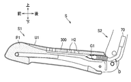
- the cushion pad P1 has a ventilation passage A1 formed inside and a plurality of ventilation holes H1 communicating with the ventilation passage A1 from the upper surface.
- the back pad P2 has a ventilation passage A2 formed inside and a plurality of ventilation holes H2 communicating with the ventilation passage A2 from the front surface.
- the ventilation passages A1 and A2 are connected to the blower 70 by a duct D described later.
- the blower 70 is a sirocco fan and is arranged below the pan frame 12 described later.
- the blower 70 is attached to the pan frame 12 via the bracket 71.
- the vehicle seat S is configured to blow out the air blown from the blower 70 toward the occupant sitting on the seat.
- the air from the blower 70 is blown out from the ventilation holes H1 and H2 through the duct D and the ventilation passages A1 and A2.
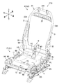
- the seat frame F includes a cushion frame F1 constituting the frame of the seat cushion S1 and a back frame F2 constituting the frame of the seat back S2.
- the seat cushion S1 is configured by covering the cushion frame F1 with the cushion pad P1 and the skin U1.
- the seat back S2 is configured by covering the back frame F2 with the back pad P2 and the skin U2 (see FIG. 1).
- the cushion frame F1 includes left and right cushion side frames 11, a pan frame 12 as a pressure receiving member, a rear pipe 13 as a rear frame, and a front pipe 14 (see FIG. 5).
- the left and right cushion side frames 11 are members that form the left and right frames of the seat cushion S1.
- the left and right cushion side frames 11 are arranged so as to face each other in the left-right direction.
- the cushion side frame 11 is made of sheet metal and is formed in a long shape that is long in the front-rear direction.
- the pan frame 12 is a plate-shaped member that receives a load from an occupant sitting on the seat.
- the width of the pan frame 12 in the left-right direction is more than half the length of the rear pipe 13.
- the pan frame 12 is made of sheet metal and is supported by left and right cushion side frames 11, a rear pipe 13, and a front pipe 14. The structure of the pan frame 12 will be described in detail later.
- the rear pipe 13 and the front pipe 14 are made of a metal pipe material.
- the rear pipe 13 and the front pipe 14 are arranged apart from each other in the front-rear direction, and connect the left and right cushion side frames 11.
- the rear pipe 13 connects the rear portions of the left and right cushion side frames 11
- the front pipe 14 connects the front portions of the left and right cushion side frames 11.
- the duct D is arranged to the right (one of the left and right directions) of the center (center surface CP) of the seat cushion S1 in the left and right direction.
- the back frame F2 includes left and right sheet metal frames 22, a pipe frame 23, a lower frame 24, and a bridge frame 25.
- the left and right sheet metal frames 22 are arranged so as to face each other in the left-right direction.
- the sheet metal frame 22 is made of sheet metal and is formed in a long shape that is long in the vertical direction.
- the pipe frame 23 is made of a metal pipe material, and has left and right upper side frames 23A and an upper frame 23B.
- the left and right upper side frames 23A extend substantially vertically.
- the upper frame 23B connects the upper ends of the upper side frame 23A to each other. Since the lower part of the left and right upper side frames 23A is connected to the upper part of the sheet metal frame 22, the left and right backside frames 21 are formed together with the left and right sheet metal frames 22.
- the left and right back side frames 21 constitute the left and right frames of the seat back S2.
- the lower frame 24 is made of sheet metal and connects the lower portions of the left and right back side frames 21 to each other.
- the crosslinked frame 25 is made of sheet metal and connects the upper portions of the left and right backside frames 21 to each other.
- the rear portion of the cushion side frame 11 and the lower portion of the back side frame 21 are rotatably connected via a reclining mechanism RL.
- the seat back S2 is connected to the seat cushion S1, and the seat back S2 can rotate back and forth with respect to the seat cushion S1.
- a motor bracket MB is provided on the sheet metal frame 22 on the right side.
- the motor bracket MB has a built-in motor for driving the reclining mechanism RL.
- the duct D may or may not be in contact with the motor bracket MB.
- the pan frame 12 has a front bottom wall W1, a central bottom wall W2, a rear bottom wall W3, a vertical wall W4, a flange W5, an inclined wall W6, and a rear wall W7.
- the front bottom wall W1 extends substantially horizontally and is arranged at the front of the cushion side frame 11.
- the vertical wall W4 extends upward from the front end and the left and right ends of the front bottom wall W1.
- the flange W5 extends outward (horizontally away from the front bottom wall W1) from the front, left and right vertical walls W4.
- the flange W5 is joined to the front portion of the cushion side frame 11.
- the central bottom wall W2 extends diagonally downward from the rear end of the front bottom wall W1.
- the central bottom wall W2 has a hole H3 through which a part of the duct D (fourth duct member 140 described later) passes through.
- Two holes H3 are arranged symmetrically with respect to the center in the left-right direction of the central bottom wall W2.
- the hole H3 on the right side is used, but in the case of the type in which the duct D is arranged on the left side of the vehicle seat S, the left side is used.
- the hole H3 may be used.
- the rear bottom wall W3 extends rearward from the rear end of the central bottom wall W2.
- the rear bottom wall W3 is arranged at a position corresponding to the buttocks of the occupant, and supports the buttocks of the occupant via the cushion pad P1 or the like.
- Inclined walls W6 are provided on both the left and right sides of the rear bottom wall W3.
- the inclined wall W6 extends obliquely from the left end or the right end of the rear bottom wall W3 toward the outer side and the upper side in the left-right direction.
- the left and right inclined walls W6 are arranged at positions corresponding to the left and right side portions of the occupant's buttocks, and support the left and right side portions of the occupant's buttocks via cushion pads P1 and the like.
- Each inclined wall W6 is gently connected to the central bottom wall W2 and the rear wall W7. Each inclined wall W6 is separated from the rear pipe 13 in the front-rear direction.
- the rear wall W7 extends diagonally upward from the rear end of the rear bottom wall W3.
- the rear end portion of the rear wall W7 is formed in a hook shape along the outer peripheral surface of the rear pipe 13, and is engaged with the rear pipe 13 from above.
- the width of the rear wall W7 in the left-right direction is smaller than the length of the rear pipe 13, and the rear wall W7 is arranged in the center of the rear pipe 13 in the left-right direction. As a result, the rear wall W7 is separated from the cushion side frame 11 in the left-right direction.
- each of the holes HR and HL is formed by being surrounded by the rear end of the inclined wall W6, the right end or the left end of the rear wall W7, the rear pipe 13, and the cushion side frame 11.
- a part of the duct D described later (a portion extending from the seat cushion S1 toward the seat back S2, specifically, a curved pipe portion 112 described later) passes through the hole HR on the right side. That is, the duct D is arranged so as to avoid the pan frame 12. In this embodiment, the curved pipe portion 112 of the duct D is not in contact with the pan frame 12.
- a part of the duct D is arranged between the rear pipe 13 and the inclined wall W6 on the right side of the pan frame 12.
- a part of the duct D is arranged between the cushion side frame 11 on the right side and the rear wall W7 of the pan frame 12.
- a part of the duct D is not in contact with the pan frame 12 and the cushion side frame 11.
- the duct D is a member that connects the ventilation passages A1 and A2 formed in the pads P (P1 and P2) of the seat cushion S1 and the seat back S2 and the blower 70.
- the duct D is formed by connecting a plurality of parts. Specifically, as shown in FIG. 4, the duct D includes a first duct member 110, a second duct member 120, a third duct member 130, and a fourth duct member 140.
- the first duct member 110 has a lower pipe portion 111, a curved pipe portion 112, and a first connecting pipe portion 113.
- the lower pipe portion 111 extends substantially back and forth.
- the curved pipe portion 112 extends upward while being curved so as to be convex rearward from the rear end of the lower pipe portion 111.
- the first connecting pipe portion 113 extends substantially upward from the upper end of the curved pipe portion 112.
- the front end of the lower pipe portion 111 is connected to the blower 70 (see FIG. 2).
- the second duct member 120 is connected to the rear portion of the first duct member 110 and is provided so as to extend substantially vertically.
- the second duct member 120 has a second connecting pipe portion 121, a first bellows portion 122, and a third connecting pipe portion 123.
- the first bellows portion 122 is provided as a flexible portion on the second connecting pipe portion 121.
- the third connecting pipe portion 123 is provided on the first bellows portion 122.
- the second connecting pipe portion 121 is formed in a size such that the first connecting pipe portion 113 of the first duct member 110 fits inside.
- the first bellows portion 122 is flexible and stretchable.
- a convex portion 123A is formed on the outer peripheral surface of the third connecting pipe portion 123.
- the convex portion 123A is formed in an annular shape over the entire circumference of the third connecting pipe portion 123 having a rectangular cross-sectional view.
- the third duct member 130 is connected to the upper end of the second duct member 120.
- the third duct member 130 has a rectangular tubular pipe portion 131 and a flange portion 132 extending from the peripheral surface of the upper end of the pipe portion 131.
- the lower end of the pipe portion 131 is fitted in the third connecting pipe portion 123 of the second duct member 120.
- the opening 131A at the upper end of the pipe portion 131 faces diagonally upward and forward, and leads to the ventilation path A2 formed in the back pad P2 (see FIG. 2).
- the fourth duct member 140 is connected to the front portion of the first duct member 110 and is provided so as to extend substantially vertically.
- the fourth duct member 140 includes a second bellows portion 141, a cushion connecting pipe portion 142 provided above the second bellows portion 141, and left and right connecting wall portions 143 provided below the second bellows portion 141. have.
- the second bellows portion 141 is flexible and stretchable.
- the cushion connecting pipe portion 142 is connected to the ventilation passage A1 formed in the cushion pad P1 (see FIG. 2).
- the connecting wall portion 143 extends downward from the lower end of the second bellows portion 141, and is provided so as to sandwich the lower pipe portion 111 of the first duct member 110 from the left and right.
- the duct D is supported by the blower 70, the cushion pad P1 and the back pad P2 to which the duct D is connected, and is not fixed to the pan frame 12.
- the duct D is arranged so as to straddle the seat cushion S1 and the seat back S2.
- the first duct member 110 and the fourth duct member 140 are mainly arranged on the seat cushion S1
- the third duct member 130 is arranged on the seat back S2
- the second duct member 120 is the seat cushion. It is arranged so as to straddle S1 and the seat back S2.
- the back pad P2 has a front side portion P21 arranged in front of the back frame F2 and a rear side portion P22 arranged after the back frame F2.
- the rear side portion P22 extends downward from the upper end portion of the front side portion P21 in a state of being spaced apart from the front side portion P21 in the front-rear direction.
- the front side portion P21 has a seat surface 211 for supporting the occupant and a bulging portion 212.
- the bulging portion 212 is arranged on the left and right and above the seat surface 211, and bulges forward from the seat surface 211.
- the front side portion P21 has a base end portion E1 and a tip end portion E2 on the opposite side of the base end portion E1.
- the base end portion E1 is located on the connecting portion side of the seat cushion S1 and the seat back S2.
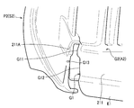
- the seat surface 211 is formed with a groove G1 for supporting the duct D and a ventilation groove G2 for forming the ventilation path A2.
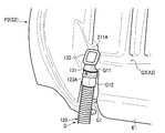
- the groove G1 is a groove into which a part of the duct D is inserted (see FIG. 8), and extends from the base end portion E1 toward the tip end portion E2.
- the groove G1 is biased to the right of the front side portion P21.
- the groove G1 is arranged at the boundary between the right side portion of the bulging portion 212 and the seat surface 211.
- the groove G1 penetrates from the occupant side of the front side portion P21 toward the side opposite to the occupant. Specifically, the groove G1 penetrates the front side portion P21 in the front-rear direction. In other words, the groove G1 penetrates the front side portion P21 extending in the vertical direction and the horizontal direction in the front-rear direction orthogonal to the vertical direction and the horizontal direction.
- the groove G1 formed in this way opens to the occupant side and also to the side opposite to the occupant.
- the upper end portion G11 of the groove G1 is smaller in width on the left and right than the base portion G12 which is another portion of the groove G1. Specifically, as shown in FIGS. 7 and 8, the upper end portion G11 of the groove G1 is formed to have a width slightly smaller than the width of the pipe portion 131 of the duct D in the left-right direction.
- the base portion G12 of the groove G1 is formed with a width larger than the maximum width in the left-right direction of the second duct member 120.
- a support surface 211A that supports the flange portion 132 of the duct D from the side opposite to the occupant is arranged.
- the support surface 211A is configured as a part of the seat surface 211.
- a concave portion G13 that engages with the convex portion 123A of the duct D is formed on the right side surface.
- the ventilation groove G2 has a first part G21, two second parts G22, two third parts G23, and two fourth parts G24.
- the two second portion G22, third portion G23, and fourth portion G24 are formed symmetrically with respect to the central CL in the left-right direction of the seat surface 211.
- the first portion G21 extends from the upper end portion G11 of the groove G1 so as to incline slightly upward toward the left.
- the first portion G21 extends to the left of the central CL in the left-right direction of the seat surface 211.
- the second part G22 extends upward from the first part G21 along the vertical direction.
- the second portion G22 is arranged closer to the central CL in the left-right direction of the seat surface 211 than the third portion G23.
- the third part G23 extends upward from the first part G21 along the vertical direction, and then inclines inward in the left-right direction and further extends upward.
- the third site G23 extends above the second site G22.
- the fourth portion G24 extends diagonally from the portion of the third portion G23 along the vertical direction toward the outer and upper sides in the left-right direction.
- Each part G22 to G24 is formed in a dead end shape that is not connected in a ring shape. Specifically, each part G22 to G24 branches and extends from the first part G21. In the direction of wind flow from the duct D supported by the groove G1, the downstream ends of the respective parts G22 to G24 are not connected to other parts (grooves). As a result, the wind blown from the duct D into the ventilation groove G2 is suppressed from colliding with each other in the ventilation groove G2.
- the seat surface 211 is covered with the slab 300 shown in FIG. 6 (b).
- the slab 300 is a sheet-like member made of urethane foam or the like, and is arranged between the skin U2 and the back pad P2 (see FIG. 2).
- the slab 300 is formed with a plurality of ventilation holes H2 penetrating in the front-rear direction.
- the ventilation hole H2 is a rectangular hole, and is elongated in the longitudinal direction of each portion G22 to G24 of the ventilation groove G2.
- the width of the ventilation hole H2 in the lateral direction is substantially the same as the width of the ventilation groove G2 in the lateral direction.
- the width of the ventilation hole H2 in the lateral direction may be slightly smaller or slightly larger than the width of the ventilation groove G2 in the lateral direction.
- At least one ventilation hole H2 is formed at a position corresponding to the downstream end of each portion G22 to G24 of the ventilation groove G2 in the wind flow direction. Specifically, one ventilation hole H2 is formed at a position corresponding to the downstream end of the second portion G22 and the fourth portion G24. Two ventilation holes H2 are formed side by side in the longitudinal direction of the third portion G23 at a position corresponding to the downstream end portion of the third portion G23.
- one ventilation hole H2 is also formed at a position near the upstream end of the second portion G22. Further, two ventilation holes H2 are formed side by side in the longitudinal direction of the third portion G23 at a position corresponding to the upstream end portion of the third portion G23.
- the connection portion of the fourth portion G24 with the third portion G23 includes two ventilation holes H2 corresponding to the downstream end portion of the third portion G23 and two ventilation holes H2 corresponding to the upstream end portion of the third portion G23. It is placed between.
- the vehicle seat S of the present embodiment configured as described above can achieve the following effects. Since the duct D is contained in the groove G1 that opens to the occupant side and extends from the base end portion E1 of the back pad P2 toward the tip end portion E2, the duct D protrudes to the back side of the back surface of the back pad P2. Can be suppressed, and the appearance of the vehicle seat S can be improved.
- the duct D supported by the groove G1 is biased to the left and right of the back pad P2, it is possible to suppress the occupant from sitting on the duct D, and it is possible to suppress the discomfort when the occupant is seated.
- the groove G1 is arranged at the boundary between the seat surface 211 and the bulging portion 212, that is, at the corner formed by the seat surface 211 and the bulging portion 212, it is possible to further suppress the occupant from sitting on the duct D. It is possible to further suppress the discomfort when the occupant is seated.
- the duct D can easily move to the opposite side of the occupant in the groove G1. Even when the portion where the D is arranged is pressed, the occupant's discomfort can be suppressed.
- the rigidity around the upper end portion G11 of the groove G1 becomes higher than the rigidity around the base portion G12, so that the rigidity becomes higher.
- the flange portion 132 can be satisfactorily supported by the portion.
- the holding force of the duct D in the groove G1 can be improved.
- the groove G1 is provided on the back pad P2, but as shown in FIG. 9, the groove G1 may be provided on the cushion pad P1.
- the blower 70 may be provided on the seat back S2.
- the groove G1 is formed so as to penetrate the back pad P2 in the front-rear direction, but the groove may be at least open to the occupant side.
- the groove G1 may be a groove with a bottom that does not open on the side opposite to the occupant.
- the groove G1 is biased to the right of the back pad P2, but the groove may be biased to the left of the pad or may be arranged in the center of the pad.
- the duct entering the groove may be arranged unevenly to the left of the pad or may be arranged in the center of the pad.
- the duct D may be passed through the hole HL shown in FIG.
- holes HC penetrating in the vertical direction are formed in the left and right centers of the rear wall W7 of the pan frame 12, and the duct D is formed in the holes HC. Just pass it through.
- the opening 131A at the upper end of the pipe portion 131 shown in FIG. 4 is directed diagonally upward and forward, but the present invention is not limited to this.
- the opening 131B of the pipe portion 131 may be directed to one side in the left-right direction, for example, the left side.
- the width (vertical length) of the connection portion G211 of the first portion G21 of the ventilation groove G2 with the duct D corresponds to the width (vertical length) of the opening 131B. It should be the same size.
- the width of the opening 131B is larger than the width of the portion of the first portion G21 on the left side of the third portion G23 on the right side and the width of the other portions G22 to G24. Therefore, the width of the portion of the first portion G21 on the right side of the third portion G23 on the right side, that is, the width of the connecting portion G211 is slightly larger than that of the opening 131B.
- the connecting portion G211 is arranged between the upper end portion G11 of the groove G1 and the third portion G23 on the right side, and is connected to the upper end portion G11 of the groove G1 and the third portion G23 on the right side.
- the concave portion G13 is formed on the side surface of the groove G1 and the convex portion 123A is formed on the outer peripheral surface of the duct D.
- a recess may be formed.
- the duct D may have a symmetrical shape with respect to the configuration described in the above embodiment. Further, the duct D may be configured not to have a curved portion (curved pipe portion 112), for example. Further, in the above-described embodiment, the duct D has the first bellows portion 122 as a flexible portion, but the flexible portion is not particularly limited as long as it has flexibility. Further, in the above-described embodiment, the duct D is formed by connecting a plurality of parts, but it may be formed of a single part. Further, the cross-sectional shape of the duct may be a polygon other than a rectangle, or may be a circle.
- the sirocco fan is exemplified as the blower device 70, but for example, a propeller fan or a turbo fan may be used.
- the vehicle seat S is configured to blow out air from the ventilation holes H1 and H2, but for example, it may be configured to suck air from the ventilation holes.
- the blower device may be one that can switch between blowing and suction by switching the rotation direction of the impeller, for example.
- the vehicle seat S is provided with the blower 70, but the vehicle seat itself may not be provided with the blower.
- the blower may be provided on the vehicle body of the vehicle on which the vehicle seat is mounted.
- the vehicle seat may be configured such that the duct is connected to, for example, an air outlet or suction port provided in the vehicle body.
- the ventilation passages connected to the blower by the duct D are formed in both the seat cushion and the seat back, but the configuration is such that only one of the seat cushion and the seat back is formed. There may be.
- the vehicle seat S mounted on the automobile is exemplified as the vehicle seat, but the seat may be mounted on a vehicle other than the automobile, for example, a railroad vehicle, a ship, an aircraft, or the like.
Landscapes
- Engineering & Computer Science (AREA)
- Aviation & Aerospace Engineering (AREA)
- Transportation (AREA)
- Mechanical Engineering (AREA)
- Chair Legs, Seat Parts, And Backrests (AREA)
- Seats For Vehicles (AREA)
Abstract
乗物用シートは、シートクッションと、シートクッションに連結されたシートバック(S2)と、送風装置とシートクッションおよびシートバック(S2)の少なくとも一方に形成された通気路(A2)とを接続するダクト(D)を備える。シートクッションまたはシートバック(S2)は、パッド(バックパッドP2)を備える。パッドは、シートクッションとシートバック(S2)の連結部分側に位置する基端部(E1)と、基端部とは反対側の先端部と、基端部(E1)から先端部に向けて延びる溝(G1)であって、少なくとも乗員側に開口する溝(G1)を有する。ダクト(D)は、溝(G1)に入っている。
Description
本発明は、乗物用シートに関する。
従来、シートクッションの下に配置された送風装置から、シートバックに向けて延びるダクトを備えた乗物用シートが知られている(特許文献1参照)。具体的に、この技術では、ダクトは、シートバックの背面側に回り込んでおり、シートバックのパッドの背面に形成された開口に接続されている。
しかしながら、従来技術では、ダクトがパッドの背面よりも外側に出っ張るため、乗物用シートの外観性が悪いという問題がある。
そこで、本発明は、ダクトがパッドの裏面よりも裏側に出っ張るのを抑制することで、乗物用シートの外観性を向上させることを目的とする。
前記した課題を解決するため、本発明に係る乗物用シートは、シートクッションと、前記シートクッションに連結されたシートバックと、送風装置と前記シートクッションおよび前記シートバックの少なくとも一方に形成された通気路とを接続するダクトと、を備える。
前記シートクッションまたは前記シートバックは、パッドを備える。
前記パッドは、前記シートクッションと前記シートバックの連結部分側に位置する基端部と、前記基端部とは反対側の先端部と、前記基端部から前記先端部に向けて延びる溝であって、少なくとも乗員側に開口する溝と、を有する。
前記ダクトは、前記溝に入っている。
前記シートクッションまたは前記シートバックは、パッドを備える。
前記パッドは、前記シートクッションと前記シートバックの連結部分側に位置する基端部と、前記基端部とは反対側の先端部と、前記基端部から前記先端部に向けて延びる溝であって、少なくとも乗員側に開口する溝と、を有する。
前記ダクトは、前記溝に入っている。
この構成によれば、少なくとも乗員側に開口し、かつ、パッドの基端部から先端部に向けて延びる溝内にダクトが入っているので、ダクトがパッドの裏面よりも裏側に出っ張るのを抑制することができ、乗物用シートの外観性を向上させることができる。
また、前記溝は、前記パッドの左右のいずれかに偏って配置されていてもよい。
これによれば、溝で支持するダクトがパッドの左右に偏るので、乗員がダクトの上に着座するのを抑制することができ、乗員の着座時の違和感を抑制することができる。
また、前記パッドは、乗員を支持する座面と、当該座面の左右に配置され、前記座面から膨出する膨出部と、を有し、前記溝は、前記座面と前記膨出部の境界に配置されていてもよい。
これによれば、溝が座面と膨出部の境界、つまり座面と膨出部とで形成される隅に配置されるので、乗員がダクトの上に着座するのをより抑制することができ、乗員の着座時の違和感をより抑制することができる。
また、前記溝は、前記パッドの乗員側から乗員とは反対側に向けて貫通していてもよい。
これによれば、ダクトが溝内において乗員とは反対側に動きやすいので、例えば乗員の手でパッドのダクトが配置される部分を押したときであっても、乗員の違和感を抑制することができる。
また、前記ダクトは、筒状のパイプ部と、当該パイプ部の先端の周面から延出するフランジ部と、を有し、前記パッドは、前記溝の端部の周囲に配置され、前記フランジ部を支持する支持面を有していてもよい。
これによれば、ダクトのフランジ部がパッドの支持面で支持されるので、ダクトが溝から外れるのを抑制することができる。
また、前記溝の前記端部は、前記溝の他の部分よりも、左右の幅が小さくてもよい。
これによれば、溝の端部の周囲の剛性が他の部分の周囲の剛性よりも高くなるので、剛性が高くなった部分でフランジ部を良好に支持することができる。
また、前記ダクトの外周面および前記溝の側面のうち、一方には、凸部が形成され、他方には、前記凸部と係合する凹部が形成されていてもよい。
これによれば、溝でのダクトの保持力を向上させることができる。
また、前記溝は、前記シートバックのパッドに設けられていてもよい。
また、前記溝は、前記シートクッションのパッドに設けられていてもよい。
また、前記乗物用シートは、前記パッドを支持するフレーム部材と、前記パッドを覆う表皮と、を備えていてもよい。
本発明によれば、少なくとも乗員側に開口し、かつ、パッドの基端部から先端部に向けて延びる溝内にダクトが入っているので、ダクトがパッドの裏面よりも裏側に出っ張るのを抑制することができ、乗物用シートの外観性を向上させることができる。
また、溝がパッドの左右のいずれかに偏って配置されることで、乗物用シートに着座した乗員に対してダクトが左右にずれた位置に配置されるので、乗員の着座時の違和感を抑制することができる。
また、溝がパッドの座面と膨出部の境界に配置されることで、乗員の着座時の違和感をより抑制することができる。
また、溝がパッドの乗員側から乗員とは反対側に向けて貫通することで、ダクトが溝内において乗員とは反対側に動きやすいので、例えば乗員の手でパッドのダクトが配置される部分を押したときであっても、乗員の違和感を抑制することができる。
また、ダクトのフランジ部がパッドの支持面で支持されることで、ダクトが溝から外れるのを抑制することができる。
また、溝の端部の左右の幅を溝の他の部分よりも小さくすることで、溝の端部の周囲の剛性が他の部分の周囲の剛性よりも高くなるので、剛性が高くなった部分でフランジ部を良好に支持することができる。
また、ダクトの外周面および溝の側面のうち、一方に、凸部が形成され、他方に、凸部と係合する凹部が形成されることで、溝でのダクトの保持力を向上させることができる。
以下、添付の図面を参照しながら、本発明の一実施形態について説明する。なお、本明細書において、前後、左右、上下は、シートに座った者から見た、前後、左右、上下を基準とする。
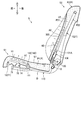
図1に示すように、本実施形態の乗物用シートは、自動車に搭載される車両用シートSとして構成されており、シートクッションS1、シートバックS2およびヘッドレストS3を備えている。
図1に示すように、本実施形態の乗物用シートは、自動車に搭載される車両用シートSとして構成されており、シートクッションS1、シートバックS2およびヘッドレストS3を備えている。
図2に示すように、車両用シートSは、フレーム部材としてのシートフレームF(図3参照)に、ウレタンフォームなどからなるパッドPと、布地や皮革などからなる表皮U1,U2を被せることで構成されている。パッドPは、シートフレームFを覆い、表皮U1,U2は、パッドPを覆っている。シートフレームFは、パッドPを支持している。
パッドPは、シートクッションS1のパッドを構成するクッションパッドP1と、シートバックS2のパッドを構成するバックパッドP2を含む。クッションパッドP1は、内部に形成された通気路A1と、上側の面から通気路A1に連通する複数の通気穴H1とを有している。また、バックパッドP2は、内部に形成された通気路A2と、前側の面から通気路A2に連通する複数の通気穴H2とを有している。
通気路A1,A2は、後述するダクトDにより送風装置70と接続されている。送風装置70は、シロッコファンであり、後述するパンフレーム12の下側に配置されている。送風装置70は、パンフレーム12にブラケット71を介して取り付けられている。車両用シートSは、送風装置70から送風された空気を、シートに座った乗員に向けて吹き出すように構成されている。送風装置70からの空気は、ダクトDと通気路A1,A2を通して通気穴H1,H2から吹き出される。
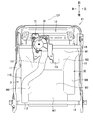
図3に示すように、シートフレームFは、シートクッションS1のフレームを構成するクッションフレームF1と、シートバックS2のフレームを構成するバックフレームF2とを含む。シートクッションS1は、クッションフレームF1をクッションパッドP1と表皮U1で覆うことで構成されている。シートバックS2は、バックフレームF2をバックパッドP2と表皮U2で覆うことで構成されている(図1参照)。
クッションフレームF1は、左右のクッションサイドフレーム11と、受圧部材としてのパンフレーム12と、後部フレームとしてのリアパイプ13と、フロントパイプ14(図5参照)とを備えている。左右のクッションサイドフレーム11は、シートクッションS1の左右のフレームを構成する部材である。左右のクッションサイドフレーム11は、左右方向に対向した状態で離間して配置されている。クッションサイドフレーム11は、板金からなり、前後に長い長尺状に形成されている。
パンフレーム12は、シートに座った乗員からの荷重を受ける板状の部材である。パンフレーム12の左右方向の幅は、リアパイプ13の長さの半分以上となっている。パンフレーム12は、板金からなり、左右のクッションサイドフレーム11、リアパイプ13およびフロントパイプ14で支持されている。なお、パンフレーム12の構造は、後で詳述する。
図5に示すように、リアパイプ13とフロントパイプ14は、金属製のパイプ材からなる。リアパイプ13とフロントパイプ14は、前後に離間して配置され、左右のクッションサイドフレーム11を連結している。詳しくは、リアパイプ13が左右のクッションサイドフレーム11の後部同士を連結しており、フロントパイプ14が左右のクッションサイドフレーム11の前部同士を連結している。ダクトDは、左右方向におけるシートクッションS1の中央(中央面CP)よりも右(左右方向の一方)に配置されている。
図3に示すように、バックフレームF2は、左右の板金フレーム22と、パイプフレーム23と、ロアフレーム24と、架橋フレーム25とを備えている。左右の板金フレーム22は、左右方向に対向した状態で離間して配置されている。板金フレーム22は、板金からなり、上下に長い長尺状に形成されている。
パイプフレーム23は、金属製のパイプ材からなり、左右のアッパーサイドフレーム23Aと、アッパーフレーム23Bとを有している。左右のアッパーサイドフレーム23Aは、略上下に延びている。アッパーフレーム23Bは、アッパーサイドフレーム23Aの上端同士を連結している。左右のアッパーサイドフレーム23Aは、下部が板金フレーム22の上部に接続されていることで、左右の板金フレーム22とともに、左右のバックサイドフレーム21を形成している。左右のバックサイドフレーム21は、シートバックS2の左右のフレームを構成する。ロアフレーム24は、板金からなり、左右のバックサイドフレーム21の下部同士を連結している。架橋フレーム25は、板金からなり、左右のバックサイドフレーム21の上部同士を連結している。
クッションサイドフレーム11の後部とバックサイドフレーム21の下部とは、リクライニング機構RLを介して回動可能に連結されている。これにより、シートバックS2がシートクッションS1に連結され、シートバックS2がシートクッションS1に対して前後に回動可能となっている。
右側の板金フレーム22には、モータブラケットMBが設けられている。モータブラケットMBには、リクライニング機構RLを駆動するためのモータが内蔵されている。なお、ダクトDは、モータブラケットMBに接触していてもよいし、接触していなくてもよい。
パンフレーム12は、前側底壁W1と、中央底壁W2と、後側底壁W3と、縦壁W4と、フランジW5と、傾斜壁W6と、後壁W7とを有している。前側底壁W1は、略水平方向に延びており、クッションサイドフレーム11の前部に配置されている。
縦壁W4は、前側底壁W1の前端および左右の各端から上方に延びている。フランジW5は、前、左右の縦壁W4から外側(前側底壁W1から水平方向に離れる方向)に向けて延びている。フランジW5は、クッションサイドフレーム11の前部に接合されている。
中央底壁W2は、前側底壁W1の後端から後ろ斜め下方に向けて延びている。中央底壁W2は、ダクトDの一部(後述する第4ダクト部材140)が通る孔H3を有している。孔H3は、中央底壁W2の左右方向中央に対して左右対称に2つ配置されている。なお、本実施形態では、ダクトDを車両用シートSの右側に配置するため、右側の孔H3を使用するが、ダクトDを車両用シートSの左側に配置するタイプの場合には、左側の孔H3を使用すればよい。
後側底壁W3は、中央底壁W2の後端から後方に向けて延びている。後側底壁W3は、乗員の臀部に対応した位置に配置され、乗員の臀部をクッションパッドP1等を介して支持している。
傾斜壁W6は、後側底壁W3の左右両側に設けられている。傾斜壁W6は、後側底壁W3の左端または右端から左右方向外側および上側に向けて斜めに延びている。左右の傾斜壁W6は、乗員の臀部の左右の側部に対応した位置に配置され、乗員の臀部の左右の側部をクッションパッドP1等を介して支持している。
各傾斜壁W6は、中央底壁W2と後壁W7とになだらかに繋がっている。各傾斜壁W6は、前後方向において、リアパイプ13から離れている。
後壁W7は、後側底壁W3の後端から後ろ斜め上に向けて斜めに延びている。後壁W7の後端部は、リアパイプ13の外周面に沿ったフック状に形成され、リアパイプ13に上から係合している。
後壁W7は、左右方向の幅がリアパイプ13の長さよりも小さく、リアパイプ13の左右方向中央に配置されている。これにより、後壁W7は、左右方向において、クッションサイドフレーム11から離れている。
以上のようにパンフレーム12が構成されることで、パンフレーム12の後部の左右には、クッションフレームF1を上下方向に貫通する孔HR,HLが形成されている。具体的に、各孔HR,HLは、傾斜壁W6の後端と、後壁W7の右端または左端と、リアパイプ13と、クッションサイドフレーム11とで囲まれることで形成されている。
そして、右側の孔HRには、後述するダクトDの一部(シートクッションS1からシートバックS2に向けて延びる部分、詳しくは、後述する湾曲管部112)が通っている。つまり、ダクトDは、パンフレーム12を避けて配置されている。なお、本実施形態では、ダクトDの湾曲管部112は、パンフレーム12に接触していない。
言い換えると、ダクトDの一部は、リアパイプ13とパンフレーム12の右側の傾斜壁W6の間に配置されている。また、ダクトDの一部は、右側のクッションサイドフレーム11とパンフレーム12の後壁W7の間に配置されている。なお、本実施形態では、ダクトDの一部は、パンフレーム12およびクッションサイドフレーム11には接触していない。
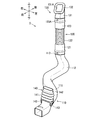
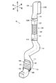
図2に示すように、ダクトDは、シートクッションS1およびシートバックS2のパッドP(P1,P2)に形成された通気路A1,A2と送風装置70を接続する部材である。ダクトDは、複数の部品を接続してなる。具体的には、図4に示すように、ダクトDは、第1ダクト部材110と、第2ダクト部材120と、第3ダクト部材130と、第4ダクト部材140とを有している。
第1ダクト部材110は、ロア管部111と、湾曲管部112と、第1接続管部113とを有している。ロア管部111は、略前後に延びている。湾曲管部112は、ロア管部111の後端から後に凸となるように湾曲しながら上方に延びている。第1接続管部113は、湾曲管部112の上端から略上方に延びている。ロア管部111は、前端部が送風装置70に接続されている(図2参照)。
第2ダクト部材120は、第1ダクト部材110の後部に接続されており、略上下に延びるように設けられている。第2ダクト部材120は、第2接続管部121と、第1蛇腹部122と、第3接続管部123とを有している。第1蛇腹部122は、第2接続管部121の上にフレキシブル部として設けられている。第3接続管部123は、第1蛇腹部122の上に設けられている。第2接続管部121は、第1ダクト部材110の第1接続管部113が内側に嵌るようなサイズに形成されている。第1蛇腹部122は、可撓性を有するとともに伸縮自在となっている。第3接続管部123の外周面には、凸部123Aが形成されている。凸部123Aは、断面視矩形の第3接続管部123の全周にわたって環状に形成されている。
第3ダクト部材130は、第2ダクト部材120の上端に接続されている。第3ダクト部材130は、矩形の筒状のパイプ部131と、パイプ部131の上端の周面から延出するフランジ部132とを有している。パイプ部131の下端部は、第2ダクト部材120の第3接続管部123内に嵌合されている。パイプ部131の上端の開口131Aは、上斜め前を向いており、バックパッドP2に形成された通気路A2に通じている(図2参照)。
第4ダクト部材140は、第1ダクト部材110の前部に接続されており、略上下に延びるように設けられている。第4ダクト部材140は、第2蛇腹部141と、第2蛇腹部141の上に設けられたクッション接続管部142と、第2蛇腹部141の下に設けられた左右の接続壁部143とを有している。第2蛇腹部141は、可撓性を有するとともに伸縮自在となっている。クッション接続管部142は、クッションパッドP1に形成された通気路A1に接続されている(図2参照)。接続壁部143は、第2蛇腹部141の下端から下方に向けて延び、第1ダクト部材110のロア管部111を左右から挟むように設けられている。なお、本実施形態では、ダクトDは、当該ダクトDが接続される送風装置70、クッションパッドP1およびバックパッドP2によって支持されており、パンフレーム12には固定されていないこととする。
図2に示すように、ダクトDは、シートクッションS1とシートバックS2とに跨がって配置されている。詳しくは、ダクトDは、主に、第1ダクト部材110と第4ダクト部材140がシートクッションS1に配置され、第3ダクト部材130がシートバックS2に配置され、第2ダクト部材120がシートクッションS1とシートバックS2を跨ぐように配置されている。
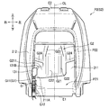
図2に示すように、バックパッドP2は、バックフレームF2の前に配置される前側部分P21と、バックフレームF2の後に配置される後側部分P22とを有している。後側部分P22は、前側部分P21と前後方向に間隔を空けた状態で、前側部分P21の上端部から下方に向けて延びている。
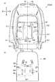
図6に示すように、前側部分P21は、乗員を支持する座面211と、膨出部212とを有している。膨出部212は、座面211の左右および上に配置され、座面211から前方に膨出する。また、前側部分P21は、基端部E1と、基端部E1とは反対側の先端部E2とを有している。基端部E1は、シートクッションS1とシートバックS2の連結部分側に位置する。
座面211には、ダクトDを支持するための溝G1と、通気路A2を形成するための通気溝G2とが形成されている。
溝G1は、ダクトDの一部が入る溝(図8参照)であり、基端部E1から先端部E2に向けて延びている。溝G1は、前側部分P21の右に偏って配置されている。詳しくは、溝G1は、膨出部212の右側部分と座面211との境界に配置されている。
溝G1は、前側部分P21の乗員側から乗員とは反対側に向けて貫通している。詳しくは、溝G1は、前側部分P21を前後方向に貫通している。言い換えると、溝G1は、上下方向および左右方向に延びる前側部分P21を、上下方向および左右方向に直交する前後方向に貫通している。このように形成された溝G1は、乗員側に開口するとともに、乗員とは反対側にも開口する。
溝G1の上端部G11は、溝G1の他の部分であるベース部G12よりも、左右の幅が小さくなっている。詳しくは、図7および図8に示すように、溝G1の上端部G11は、ダクトDのパイプ部131の左右方向の幅よりも若干小さい幅で形成されている。溝G1のベース部G12は、第2ダクト部材120の左右方向の最大幅よりも大きな幅で形成されている。
溝G1の上端部G11の周囲には、ダクトDのフランジ部132を乗員とは反対側から支持する支持面211Aが配置されている。支持面211Aは、座面211の一部として構成されている。溝G1のベース部G12の左右の側面のうち、右側の側面には、ダクトDの凸部123Aと係合する凹部G13が形成されている。
図6(a)に戻って、通気溝G2は、第1部位G21と、2つの第2部位G22と、2つの第3部位G23と、2つの第4部位G24とを有している。2つの、第2部位G22、第3部位G23および第4部位G24は、座面211の左右方向の中央CLを基準に左右対称に形成されている。
第1部位G21は、溝G1の上端部G11から左に向けて若干上に傾斜するように延びている。第1部位G21は、座面211の左右方向の中央CLよりも左に延びている。
第2部位G22は、第1部位G21から上下方向に沿って上に延びている。第2部位G22は、第3部位G23よりも座面211の左右方向の中央CLの近くに配置されている。
第3部位G23は、第1部位G21から上下方向に沿って上に延びた後、左右方向内側に傾斜してさらに上に延びている。第3部位G23は、第2部位G22よりも上に延びている。
第4部位G24は、第3部位G23のうち上下方向に沿った部分から左右方向外側および上側に向けて斜めに延びている。
各部位G22~G24は、それぞれ、環状には接続されない袋小路状に形成されている。詳しくは、各部位G22~G24は、第1部位G21から枝分かれして延びている。溝G1で支持されるダクトDからの風の流れ方向において、各部位G22~G24の下流端部は、他の部位(溝)に接続されていない。これにより、ダクトDから通気溝G2内に送風されてくる風が、通気溝G2内でぶつかり合うことが抑制されている。
座面211は、図6(b)に示すスラブ300によって覆われている。スラブ300は、ウレタンフォームなどからなるシート状の部材であり、表皮U2とバックパッドP2との間に配置される(図2参照)。スラブ300には、前後方向に貫通する複数の通気穴H2が形成されている。
通気穴H2は、矩形の孔であり、通気溝G2の各部位G22~G24の長手方向に長くなっている。通気穴H2の短手方向の幅は、通気溝G2の短手方向の幅と略同じとなっている。なお、通気穴H2の短手方向の幅は、通気溝G2の短手方向の幅よりも若干小さくてもよいし、若干大きくてもよい。
風の流れ方向における、通気溝G2の各部位G22~G24の下流端部に対応する位置には、少なくとも1つの通気穴H2が形成されている。詳しくは、第2部位G22および第4部位G24の下流端部に対応する位置には、1つの通気穴H2が形成されている。第3部位G23の下流端部に対応する位置には、2つの通気穴H2が第3部位G23の長手方向に並んで形成されている。
また、第2部位G22の上流端部寄りの位置にも、1つの通気穴H2が形成されている。また、第3部位G23の上流端部に対応する位置にも、2つの通気穴H2が第3部位G23の長手方向に並んで形成されている。第4部位G24の第3部位G23との接続部分は、第3部位G23の下流端部に対応した2つの通気穴H2と、第3部位G23の上流端部に対応した2つの通気穴H2との間に配置されている。
以上のように構成された本実施形態の車両用シートSでは、次の各効果を奏することができる。
乗員側に開口し、かつ、バックパッドP2の基端部E1から先端部E2に向けて延びる溝G1内にダクトDが入っているので、ダクトDがバックパッドP2の裏面よりも裏側に出っ張るのを抑制することができ、車両用シートSの外観性を向上させることができる。
乗員側に開口し、かつ、バックパッドP2の基端部E1から先端部E2に向けて延びる溝G1内にダクトDが入っているので、ダクトDがバックパッドP2の裏面よりも裏側に出っ張るのを抑制することができ、車両用シートSの外観性を向上させることができる。
溝G1で支持するダクトDがバックパッドP2の左右に偏っているので、乗員がダクトDの上に着座するのを抑制することができ、乗員の着座時の違和感を抑制することができる。
溝G1が座面211と膨出部212の境界、つまり座面211と膨出部212とで形成される隅に配置されるので、乗員がダクトDの上に着座するのをより抑制することができ、乗員の着座時の違和感をより抑制することができる。
溝G1がバックパッドP2の乗員側から乗員とは反対側に向けて貫通することで、ダクトDが溝G1内において乗員とは反対側に動きやすいので、例えば乗員の手でバックパッドP2のダクトDが配置される部分を押したときであっても、乗員の違和感を抑制することができる。
ダクトDのフランジ部132がバックパッドP2の支持面211Aで支持されるので、ダクトDが溝G1から外れるのを抑制することができる。
溝G1の上端部G11の左右の幅をベース部G12よりも小さくすることで、溝G1の上端部G11の周囲の剛性がベース部G12の周囲の剛性よりも高くなるので、剛性が高くなった部分でフランジ部132を良好に支持することができる。
ダクトDの外周面に形成した凸部123Aを、溝G1の側面に形成した凹部G13に係合させるので、溝G1でのダクトDの保持力を向上させることができる。
以上に本発明の実施形態について説明したが、本発明は、以下の他の形態に示すように、適宜変形して実施することが可能である。
前記実施形態では、溝G1をバックパッドP2に設けたが、図9に示すように、溝G1をクッションパッドP1に設けてもよい。なお、この場合、送風装置70は、シートバックS2に設けてもよい。
前記実施形態では、バックパッドP2を前後方向に貫通するように溝G1を形成したが、溝は、少なくとも乗員側に開口していればよい。例えば、図9に示すように、溝G1を、乗員とは反対側には開口しない、底付きの溝としてもよい。
前記実施形態では、溝G1をバックパッドP2の右に偏って配置したが、溝は、パッドの左に偏って配置されていてもよいし、パッドの中央に配置されていてもよい。なお、この場合、溝に入るダクトを、パッドの左に偏って配置してもよいし、パッドの中央に配置してもよい。なお、ダクトをパッドの左に偏って配置する場合には、図3に示す孔HLにダクトDを通せばよい。
また、ダクトをパッドの中央に配置する場合には、図10に示すように、パンフレーム12の後壁W7の左右中央に、上下方向に貫通する孔HCを形成し、この孔HCにダクトDを通せばよい。
前記実施形態では、図4に示すパイプ部131の上端の開口131Aを上斜め前に向けたが、本発明はこれに限定されるものではない。例えば、図11に示すように、パイプ部131の開口131Bを、左右方向の一方、例えば左側に向けてもよい。この場合、図12に示すように、通気溝G2の第1部位G21のダクトDとの接続部分G211の幅(上下方向の長さ)を、開口131Bの幅(上下方向の長さ)に対応した大きさとすればよい。
詳しくは、この形態では、開口131Bの幅は、第1部位G21のうち右側の第3部位G23よりも左側の部分の幅や、その他の部位G22~G24の幅よりも大きい。そのため、第1部位G21のうち右側の第3部位G23よりも右側の部分、つまり、接続部分G211の幅を開口131Bよりも若干大きい幅にしている。接続部分G211は、溝G1の上端部G11と右側の第3部位G23の間に配置され、溝G1の上端部G11と右側の第3部位G23とに繋がっている。
前記実施形態では、溝G1の側面に凹部G13を形成し、ダクトDの外周面に凸部123Aを形成したが、溝の側面に凸部を形成し、ダクトの外周面に凸部と係合する凹部を形成してもよい。
なお、ダクトDは、前記実施形態で説明した構成に対し、左右対称の形状を有する構成であってもよい。また、ダクトDは、例えば、湾曲する部分(湾曲管部112)を備えない構成であってもよい。また、前記実施形態では、ダクトDがフレキシブル部として第1蛇腹部122を有していたが、フレキシブル部は、可撓性を有するものであれば、その構成は特に問わない。また、前記実施形態では、ダクトDが複数の部品を接続してなるものであったが、単一の部品からなるものであってもよい。また、ダクトの断面形状は、矩形以外の多角形であってもよいし、円形であってもよい。
また、前記実施形態では、送風装置70としてシロッコファンを例示したが、例えば、プロペラファンやターボファンなどであってもよい。また、前記実施形態では、車両用シートSが通気穴H1,H2から空気を吹き出すように構成されていたが、例えば、通気穴から空気を吸い込むように構成されていてもよい。
また、送風装置は、例えば、羽根車の回転方向を切り替えることで、送風と吸引を切り替えることができるものであってもよい。また、前記実施形態では、車両用シートSが送風装置70を備えていたが、車両用シート自体は送風装置を備えない構成であってもよい。言い換えると、送風装置は、車両用シートが搭載される自動車の車体に設けられていてもよい。この場合、車両用シートは、ダクトが、例えば、車体に設けられた空気の吹出口または吸引口に接続される構成とすることができる。
また、前記実施形態では、ダクトDにより送風装置と接続される通気路が、シートクッションおよびシートバックの両方に形成されていたが、シートクッションおよびシートバックのいずれか一方だけに形成された構成であってもよい。
また、前記実施形態では、乗物用シートとして自動車に搭載される車両用シートSを例示したが、自動車以外の乗物、例えば、鉄道車両や船舶、航空機などに搭載されるシートであってもよい。
また、前記した実施形態および変形例で説明した各要素を、任意に組み合わせて実施してもよい。
Claims (10)
- シートクッションと、
前記シートクッションに連結されたシートバックと、
送風装置と前記シートクッションおよび前記シートバックの少なくとも一方に形成された通気路とを接続するダクトと、を備える乗物用シートであって、
前記シートクッションまたは前記シートバックは、パッドを備え、
前記パッドは、
前記シートクッションと前記シートバックの連結部分側に位置する基端部と、
前記基端部とは反対側の先端部と、
前記基端部から前記先端部に向けて延びる溝であって、少なくとも乗員側に開口する溝と、を有し、
前記ダクトは、前記溝に入っていることを特徴とする乗物用シート。 - 前記溝は、前記パッドの左右のいずれかに偏って配置されていることを特徴とする請求項1に記載の乗物用シート。
- 前記パッドは、
乗員を支持する座面と、
当該座面の左右に配置され、前記座面から膨出する膨出部と、を有し、
前記溝は、前記座面と前記膨出部の境界に配置されていることを特徴とする請求項2に記載の乗物用シート。 - 前記溝は、前記パッドの乗員側から乗員とは反対側に向けて貫通していることを特徴とする請求項1から請求項3のいずれか1項に記載の乗物用シート。
- 前記ダクトは、
筒状のパイプ部と、
当該パイプ部の先端の周面から延出するフランジ部と、を有し、
前記パッドは、
前記溝の端部の周囲に配置され、前記フランジ部を支持する支持面を有することを特徴とする請求項1から請求項4のいずれか1項に記載の乗物用シート。 - 前記溝の前記端部は、前記溝の他の部分よりも、左右の幅が小さいことを特徴とする請求項5に記載の乗物用シート。
- 前記ダクトの外周面および前記溝の側面のうち、一方には、凸部が形成され、他方には、前記凸部と係合する凹部が形成されていることを特徴とする請求項1から請求項6のいずれか1項に記載の乗物用シート。
- 前記溝は、前記シートバックのパッドに設けられることを特徴とする請求項1から請求項7のいずれか1項に記載の乗物用シート。
- 前記溝は、前記シートクッションのパッドに設けられることを特徴とする請求項1から請求項7のいずれか1項に記載の乗物用シート。
- 前記パッドを支持するフレーム部材と、
前記パッドを覆う表皮と、を備えたことを特徴とする請求項1から請求項9のいずれか1項に記載の乗物用シート。
Applications Claiming Priority (2)
| Application Number | Priority Date | Filing Date | Title |
|---|---|---|---|
| JP2020043697A JP7428885B2 (ja) | 2020-03-13 | 2020-03-13 | 乗物用シート |
| JP2020-043697 | 2020-03-13 |
Publications (1)
| Publication Number | Publication Date |
|---|---|
| WO2021182053A1 true WO2021182053A1 (ja) | 2021-09-16 |
Family
ID=77671428
Family Applications (1)
| Application Number | Title | Priority Date | Filing Date |
|---|---|---|---|
| PCT/JP2021/006049 Ceased WO2021182053A1 (ja) | 2020-03-13 | 2021-02-18 | 乗物用シート |
Country Status (2)
| Country | Link |
|---|---|
| JP (1) | JP7428885B2 (ja) |
| WO (1) | WO2021182053A1 (ja) |
Families Citing this family (2)
| Publication number | Priority date | Publication date | Assignee | Title |
|---|---|---|---|---|
| JP7832471B2 (ja) * | 2022-01-20 | 2026-03-18 | テイ・エス テック株式会社 | 乗物用シート |
| JP7851233B2 (ja) * | 2022-11-25 | 2026-04-24 | テイ・エス テック株式会社 | 乗り物用シート |
Citations (4)
| Publication number | Priority date | Publication date | Assignee | Title |
|---|---|---|---|---|
| JP2005200009A (ja) * | 2004-01-12 | 2005-07-28 | Wet Automotive Syst Ag | 車室構成要素用空調装置、空調式車両シート、そして車室構成要素を空気調和するための方法 |
| KR101284313B1 (ko) * | 2011-11-14 | 2013-07-08 | 현대자동차주식회사 | 차량시트의 프레임 일체형 백커버 |
| JP2014094622A (ja) * | 2012-11-08 | 2014-05-22 | Toyota Boshoku Corp | 乗物用シート |
| JP2019026255A (ja) * | 2017-07-31 | 2019-02-21 | テイ・エス テック株式会社 | 乗物用シート |
Family Cites Families (1)
| Publication number | Priority date | Publication date | Assignee | Title |
|---|---|---|---|---|
| JP6641552B2 (ja) | 2016-05-27 | 2020-02-05 | トヨタ紡織株式会社 | 乗物用シート |
-
2020
- 2020-03-13 JP JP2020043697A patent/JP7428885B2/ja active Active
-
2021
- 2021-02-18 WO PCT/JP2021/006049 patent/WO2021182053A1/ja not_active Ceased
Patent Citations (4)
| Publication number | Priority date | Publication date | Assignee | Title |
|---|---|---|---|---|
| JP2005200009A (ja) * | 2004-01-12 | 2005-07-28 | Wet Automotive Syst Ag | 車室構成要素用空調装置、空調式車両シート、そして車室構成要素を空気調和するための方法 |
| KR101284313B1 (ko) * | 2011-11-14 | 2013-07-08 | 현대자동차주식회사 | 차량시트의 프레임 일체형 백커버 |
| JP2014094622A (ja) * | 2012-11-08 | 2014-05-22 | Toyota Boshoku Corp | 乗物用シート |
| JP2019026255A (ja) * | 2017-07-31 | 2019-02-21 | テイ・エス テック株式会社 | 乗物用シート |
Also Published As
| Publication number | Publication date |
|---|---|
| JP2021142922A (ja) | 2021-09-24 |
| JP7428885B2 (ja) | 2024-02-07 |
Similar Documents
| Publication | Publication Date | Title |
|---|---|---|
| US8702165B2 (en) | Vehicle seat | |
| CN107249931B (zh) | 车辆用座椅 | |
| JP5998860B2 (ja) | 乗物用シート | |
| WO2005096893A1 (ja) | 車両用シート | |
| JP6627607B2 (ja) | 車両用シート | |
| JP6356882B1 (ja) | シートへのセンサーの配置構造 | |
| JP7663803B2 (ja) | 乗物用シート | |
| WO2005096891A1 (ja) | 車両用シート | |
| JP7227449B2 (ja) | 乗物用シート | |
| JP2016094072A (ja) | 車両用シート | |
| JP7428885B2 (ja) | 乗物用シート | |
| JP2024033231A (ja) | 車両用シート | |
| JP7317459B2 (ja) | 乗物用シート | |
| JP2020157856A (ja) | 乗物用シート | |
| JP2006137362A (ja) | 座席用空調装置 | |
| JP7157300B2 (ja) | 乗物用シート | |
| JP2001180343A (ja) | 中折れシートバック | |
| JP2012206649A (ja) | 車両用シート | |
| JP5994674B2 (ja) | 車両用シート | |
| JP7795445B2 (ja) | 乗り物用シート | |
| JP7851233B2 (ja) | 乗り物用シート | |
| JP2021061875A (ja) | 乗物用シート | |
| US20250276625A1 (en) | Blower protection structure of a seatback, and vehicle seat | |
| JP2026049461A (ja) | 車両用シート | |
| JP2023053010A (ja) | 乗物用シート |
Legal Events
| Date | Code | Title | Description |
|---|---|---|---|
| 121 | Ep: the epo has been informed by wipo that ep was designated in this application |
Ref document number: 21767430 Country of ref document: EP Kind code of ref document: A1 |
|
| NENP | Non-entry into the national phase |
Ref country code: DE |
|
| 122 | Ep: pct application non-entry in european phase |
Ref document number: 21767430 Country of ref document: EP Kind code of ref document: A1 |