WO2021182020A1 - ロボット制御システム、ロボット制御方法、及び記録媒体 - Google Patents
ロボット制御システム、ロボット制御方法、及び記録媒体 Download PDFInfo
- Publication number
- WO2021182020A1 WO2021182020A1 PCT/JP2021/005453 JP2021005453W WO2021182020A1 WO 2021182020 A1 WO2021182020 A1 WO 2021182020A1 JP 2021005453 W JP2021005453 W JP 2021005453W WO 2021182020 A1 WO2021182020 A1 WO 2021182020A1
- Authority
- WO
- WIPO (PCT)
- Prior art keywords
- map
- robot
- control system
- robot control
- movement
- Prior art date
- Legal status (The legal status is an assumption and is not a legal conclusion. Google has not performed a legal analysis and makes no representation as to the accuracy of the status listed.)
- Ceased
Links
Images


Classifications
-
- G—PHYSICS
- G05—CONTROLLING; REGULATING
- G05D—SYSTEMS FOR CONTROLLING OR REGULATING NON-ELECTRIC VARIABLES
- G05D1/00—Control of position, course, altitude or attitude of land, water, air or space vehicles, e.g. using automatic pilots
- G05D1/02—Control of position or course in two dimensions
Definitions
- the present invention relates to a technical field of a robot control system for controlling the operation of a robot, a robot control method, and a recording medium.
- Patent Document 1 discloses a technique of searching for a movement path of a robot on a grid and moving the robot along a movement path that minimizes the search cost of the path.
- Patent Document 2 discloses a technique of setting different costs in the vertical and horizontal directions and the diagonal direction of the mesh and searching for a movement route that minimizes the total cost.
- Japanese Unexamined Patent Publication No. 2010-191502 Japanese Unexamined Patent Publication No. 63-200207
- the present invention has been made in view of the above problems, and an object of the present invention is to provide a robot control system, a robot control method, and a recording medium capable of moving a robot in an arbitrary direction.
- One aspect of the robot control system of the present invention is a first map which is an occupied grid map including information on a movement range and a movement direction of the robot, and the first map which has a predetermined inclination with respect to the first map and the first one.
- the route generation means for generating the movement route of the robot and the robot are controlled so as to move along the movement route.
- the robot includes a control means for controlling the traveling direction of the robot based on the predetermined inclination.
- One aspect of the robot control method of the present invention is a first map which is an occupied grid map including information on a range and a direction in which a robot can move, and the first map which has a predetermined inclination with respect to the first map and the first one.
- the second map which is the occupied grid map coupled to the map of 1
- the robot is controlled so as to move along the movement path, and the movement is performed.
- the route includes both the first map and the second map
- the traveling direction of the robot is controlled based on the predetermined inclination.
- One aspect of the recording medium of the present invention is the first map, which is an occupied grid map containing information on the range and direction in which the robot can move, and the first map, which has a predetermined inclination with respect to the first map.
- a second map which is the occupied grid map coupled to the map of the above, is used to generate a movement path of the robot, control the robot so as to move along the movement path, and control the movement path.
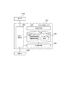
- FIG. 1 is a block diagram showing a hardware configuration of the robot control system according to the first embodiment.
- the robot control system 1000 includes a CPU (Central Processing Unit) 11, a RAM (Random Access Memory) 12, a ROM (Read Only Memory) 13, and a storage device 14. It has.
- the robot control system 1000 may further include an input device 15 and an output device 16.
- the CPU 11, the RAM 12, the ROM 13, the storage device 14, the input device 15, and the output device 16 are connected via the data bus 17.
- the CPU 11 reads a computer program.
- the CPU 11 is configured to read a computer program stored in at least one of the RAM 12, the ROM 13, and the storage device 14.
- the CPU 11 may read a computer program stored in a computer-readable recording medium using a recording medium reading device (not shown).
- the CPU 11 may acquire (that is, may read) a computer program from a device (not shown) located outside the robot control system 1000 via a network interface.
- the CPU 11 controls the RAM 12, the storage device 14, the input device 15, and the output device 16 by executing the read computer program.
- a functional block for controlling the robot is realized in the CPU 11.
- the RAM 12 temporarily stores the computer program executed by the CPU 11.
- the RAM 12 temporarily stores data temporarily used by the CPU 11 when the CPU 11 is executing a computer program.
- the RAM 12 may be, for example, a D-RAM (Dynamic RAM).
- the ROM 13 stores a computer program executed by the CPU 11.
- the ROM 13 may also store fixed data.
- the ROM 13 may be, for example, a P-ROM (Programmable ROM).
- the storage device 14 stores data stored in the robot control system 1000 for a long period of time.
- the storage device 14 may operate as a temporary storage device of the CPU 11.
- the storage device 14 may include, for example, at least one of a hard disk device, a magneto-optical disk device, an SSD (Solid State Drive), and a disk array device.
- the input device 15 is a device that receives an input instruction from the user of the robot control system 1000.
- the input device 15 may include, for example, at least one of a keyboard, a mouse and a touch panel.
- the output device 16 is a device that outputs information about the robot control system 1000 to the outside.
- the output device 16 may be a display device (for example, a display) capable of displaying information about the robot control system 1000.
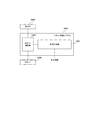
- FIG. 2 is a block diagram showing an overall configuration of the robot control system according to the first embodiment.
- FIG. 3 is a block diagram showing a connection configuration between the robot control system and the robot according to the first embodiment.
- the robot control system 1000 is configured as a system capable of controlling the operation of the robot 2000.
- the robot 2000 here is configured to be capable of executing at least a moving operation, and how it moves can be controlled by the robot control system 1000.
- the robot control system 1000 controls the operation of the robot in response to the input of the operator 3000.
- the robot control system 1000 includes a map database 1100, a map creation unit 1200, a route generation unit 1300, and a robot control unit 1400 as components for realizing the function.
- the map database 1100 is configured to store map information. More specifically, the map database 1100 is configured to store the map 1110 and the map combination information 1120. Specific examples of various information stored in the map database 1100 will be described in detail later.
- the map creation unit 1200 is configured to be able to create map information.
- the map creation unit 1200 creates a map 1110 in response to an operation of, for example, an operator 3000. Further, the map creation unit 1200 is configured so that at least two created maps 1110 can be combined. A specific method of combining the maps 1110 by the map creation unit 1200 will be described in detail later.
- the map information created by the map creation unit 1200 is stored in the map database 1100.
- the route generation unit 1300 is configured to be able to generate the movement route of the robot 2000.
- the route generation unit 1300 generates the movement route of the robot 2000 by using the information stored in the map database 1100. A specific method for purifying the migration route by the route generation unit 1300 will be described in detail later.
- the movement path generated by the route generation unit 1300 is output to the robot control unit 1400.
- the robot control unit 1400 is configured to be able to control the movement of the robot 2000. However, the robot control unit 1400 may be configured to be able to control operations other than the movement of the robot 2000.
- the robot control unit 1400 controls the robot 2000 so as to move along the movement path generated by the route generation unit 1300. Although one robot 2000 is shown here for convenience of explanation, the robot control unit 1400 may be able to control the operations of the plurality of robots 2000, respectively.
- the robot system 1000 and the robot 2000 are connected to each other via the wireless system 4000. Specifically, the operation of the robot 2000 is controlled by transmitting the signal output from the robot control unit 1400 to the robot 2000 via the wireless system 4000. Further, the robot 2000 may be configured so that information or the like indicating the current situation can be output to the robot control unit 1400.
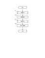
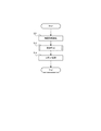
- FIG. 4 is a flowchart showing the overall operation flow of the robot control system according to the first embodiment.
- FIG. 5 is a flowchart showing the flow of operation of the map creation process by the robot control system according to the first embodiment.
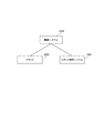
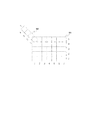
- FIG. 6 is a conceptual diagram showing an example of a map created by the map creation unit.
- FIG. 7 is a conceptual diagram showing a method of connecting the first map and the second map.
- the map creation unit 1200 creates the first map (step S111). Subsequently, the map creation unit 1200 creates a second map different from the first map (step S112). Then, the map creation unit 1200 combines the first map and the second map (step S113).
- the map 1110 is created as an occupied grid map (OGM: Occupancy Grid Map).
- the map 1110 is information including the range in which the robot 2000 can move and the rules at the time of movement.
- the map 1110 has a movable area 1111a (that is, a white square in the figure) in which the robot can move and a movement prohibited area 1111b (that is, a shaded square in the figure) in which the robot cannot move. Includes.
- a moving direction D that is, a triangular arrow mark in the drawing, which is a direction in which the robot can move, is set.
- the map 1110 includes information regarding the map inclination ⁇ indicating how much the map is inclined with respect to the reference coordinate axis.
- the first map and the second map are created so that at least the map inclination ⁇ has a different value.
- the first map M1 and the second map M2 are connected to each other by one area of each map.
- the area (1,5) in the first map M1 and the area (1,1) in the second map M2 are combined.
- the map database 1100 stores (stores) the created map information (step S12).
- the map database 1100 stores the map 1110 and the map combination information 1120, as described above.
- the map combination information 1120 will be specifically described with reference to FIG.
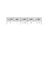
- FIG. 8 is a table showing an example of map combination information stored in the map database.
- the map combination information 1120 has a link number, a map ID of two maps to be combined (that is, a first map M1 and a second map M2), and a mass number to be combined.
- the link number is a number for managing the connection points, and as the number of connection points increases, the number increases like 2, 3, 4, ....
- the map ID is an ID for identifying the map 1110.
- the map ID "1" corresponds to the first map M1
- the map ID "2" corresponds to the second map M2. ..
- the square numbers are information indicating the connected areas, and in the example of FIG. 8, the squares of (1,5) on the first map M1 and the squares (1,1) of the second map M2 are used. Indicates that they are bound.
- FIG. 9 is a flowchart showing an operation flow of a route generation process by the robot control system according to the first embodiment.
- the route generation unit 1300 searches for the route to be moved by the robot 2000 (step S131).
- the route search is performed based on, for example, the movement start point and the movement end point of the robot 2000.
- the route generation unit 1300 determines whether or not the area to be the search range includes a combined area (that is, an area where two maps are combined) (step S132). Then, when the combined area is included in the search range, the route generation unit 1300 searches not only the map 1110 that started the search but also the map 1110 of the combined destination (step S133). For example, the route generation unit 1300 searches not only the first map M1 but also the second map M2 coupled to the first map M1. On the other hand, when the search range includes the combined area, the route generation unit 1300 searches only the map 1110 that started the search (that is, step S133 is omitted). For example, when the search is started from the first map M1, the route generation unit 1300 searches only the first map M1 without searching the second map M2.
- a combined area that is, an area where two maps are combined
- the route generation unit 1300 outputs a movement route to be moved by the robot 2000 as a route search result.
- a route search result As for the method of determining an appropriate movement route by search, an existing technique can be appropriately adopted, and therefore a specific description thereof will be omitted here.
- the robot control unit 140 controls the movement of the robot 2000 based on the generated movement route.
- the robot 2000 moves along the movement path generated by the route generation process.
- the robot 2000 uses the area where the first map M1 and the second map M2 are connected (in other words, the area where the first map M1 and the second map M2 are connected).
- the area where the route of the first map M1 and the route of the second map M2 intersect) is controlled to change direction (turn).
- a movement route is searched using a combination of a plurality of maps 1110.
- the plurality of maps 1110 have different map inclinations ⁇ . That is, the plurality of maps 1110 are diagonally connected to each other.
- the robot 2000 can be moved in an oblique direction by searching for a movement route using the combined map.
- the robot 2000 can move only in the vertical direction or the horizontal direction of the figure.
- the second map M2 coupled to the first map M1 it is possible to move in the diagonal direction of the figure.
- the robot 2000 can be moved in an arbitrary direction.
- the robot 2000 If the robot 2000 is to be moved in an arbitrary direction with only one map 1110, it is necessary to reduce the interval between the grids (areas), which increases the load of route search. Further, since the robot 2000 moves diagonally with respect to the grid, the movement locus of the robot 2000 and the movement rule of the area cannot be intuitively expressed. However, according to the robot control system 1000 according to the first embodiment, the robot 2000 can be moved diagonally without reducing the grid spacing. Further, since the robot 2000 moves along the grid to the last, the movement locus of the robot 2000 and the movement rule of the area can be intuitively expressed.
- FIG. 10 is a block diagram showing the overall configuration of the robot control system according to the second embodiment.
- the same components as those shown in FIG. 2 are designated by the same reference numerals.
- the robot control system 1000 according to the second embodiment includes a route generation unit 1300 and a robot control unit 1400. That is, the robot control system 1000 according to the second embodiment does not include the map database 1100 described in the first embodiment and the map creation unit 1200 (see FIG. 2).
- FIG. 11 is a flowchart showing the overall operation flow of the robot control system according to the second embodiment.
- the same reference numerals are given to the same processes as those shown in FIG.
- the route generation unit 1300 reads map information from outside the system (step S31).
- the map information read from the outside of the system is a combination of a plurality of maps 1110 as described in the first embodiment.
- the route generation unit 1300 After reading the map information, the route generation unit 1300 generates a movement route using the map information (step S13), and the robot control unit 1400 controls the movement of the robot 2000 based on the movement route (step S14). In this way, if the map information is acquired from the outside, the robot control system 1000 itself does not need to include the map database 1100 and the map creation unit 1200.
- the movement path of the robot 2000 is based on map information (information in which a plurality of maps 1110 are combined) acquired from the outside. Is generated. Therefore, the robot 2000 can be moved in an arbitrary direction as in the first embodiment described above.
- the robot control system has a first map which is an occupied grid map including information on a movement range and a movement direction of the robot, and the first map which has a predetermined inclination with respect to the first map.
- the route generation means for generating the movement route of the robot and the robot are controlled so as to move along the movement route.
- the movement route includes both the first map and the second map
- the movement route includes a control means for controlling the traveling direction of the robot based on the predetermined inclination. It is a robot control system.
- Appendix 2 The robot control system according to Appendix 2 is the robot control system according to Appendix 1, wherein the second map indicates a movement direction that intersects the movement direction indicated by the first map at an angle. be.
- the robot control system according to Appendix 3 is characterized by further comprising a map creation means for creating the first map and the second map, and combining the first map and the second map.
- Appendix 4 The robot control system according to Appendix 4 is characterized in that the map-creating means connects a first area on the first map and a second area on the second map. The robot control system described.
- Appendix 5 The robot according to any one of Appendix 1 to 4, wherein the robot control system according to Appendix 5 further includes a map storage means for storing information about the first map and the second map. It is a control system.
- the map storage means is such that the map information of the first map and the second map is combined with the first map and the second map.
- the combined information includes information on the first area in the first map and information on the second area in the second map combined with the first area.
- the robot control method has a first map which is an occupied grid map including information on a range and a direction in which the robot can move, and the first map which has a predetermined inclination with respect to the first map and the first map.
- the second map which is the occupied grid map coupled to the map
- the movement path of the robot is generated, the robot is controlled so as to move along the movement path, and the movement path is set to the movement path.
- the robot control method is characterized in that when both the first map and the second map are included, the traveling direction of the robot is controlled based on the predetermined inclination.
- the computer program according to Appendix 10 has a first map which is an occupied grid map including information on a range and a direction in which a robot can move, and the first map which has a predetermined inclination with respect to the first map.
- a second map which is the occupied grid map coupled to the above, is used to generate a movement path of the robot, control the robot so as to move along the movement path, and connect the movement path to the movement path.
- It is a computer program characterized by operating a computer so as to control the traveling direction of the robot based on the predetermined inclination when both the first map and the second map are included. ..
- the present invention is not limited to the above embodiment.
- the present invention can be appropriately modified within the scope of the claims and within the scope not contrary to the gist or idea of the invention that can be read from the entire specification, and the robot control system, the robot control method, and the recording medium accompanied by such changes. Is also included in the technical idea of the present invention.
- Robot control system 1100 Map database 1110 Map information 1111a Movable area 1111b Movable area 1120 Map combination information 1200 Map creation unit 1300 Route generation unit 1400 Robot control unit 2000 Robot 3000 Operator 4000 Wireless system M1 1st map M2 2nd Map D Movement direction ⁇ Map tilt
Landscapes
- Engineering & Computer Science (AREA)
- Aviation & Aerospace Engineering (AREA)
- Radar, Positioning & Navigation (AREA)
- Remote Sensing (AREA)
- Physics & Mathematics (AREA)
- General Physics & Mathematics (AREA)
- Automation & Control Theory (AREA)
- Control Of Position, Course, Altitude, Or Attitude Of Moving Bodies (AREA)
- Manipulator (AREA)
Priority Applications (1)
| Application Number | Priority Date | Filing Date | Title |
|---|---|---|---|
| JP2022505860A JPWO2021182020A1 (enExample) | 2020-03-10 | 2021-02-15 |
Applications Claiming Priority (2)
| Application Number | Priority Date | Filing Date | Title |
|---|---|---|---|
| JP2020040932 | 2020-03-10 | ||
| JP2020-040932 | 2020-03-10 |
Publications (1)
| Publication Number | Publication Date |
|---|---|
| WO2021182020A1 true WO2021182020A1 (ja) | 2021-09-16 |
Family
ID=77672263
Family Applications (1)
| Application Number | Title | Priority Date | Filing Date |
|---|---|---|---|
| PCT/JP2021/005453 Ceased WO2021182020A1 (ja) | 2020-03-10 | 2021-02-15 | ロボット制御システム、ロボット制御方法、及び記録媒体 |
Country Status (2)
| Country | Link |
|---|---|
| JP (1) | JPWO2021182020A1 (enExample) |
| WO (1) | WO2021182020A1 (enExample) |
Cited By (1)
| Publication number | Priority date | Publication date | Assignee | Title |
|---|---|---|---|---|
| WO2025113122A1 (zh) * | 2023-12-01 | 2025-06-05 | 珠海一微半导体股份有限公司 | 基于参考引导方向的回充控制方法 |
Citations (2)
| Publication number | Priority date | Publication date | Assignee | Title |
|---|---|---|---|---|
| JP2018038291A (ja) * | 2016-09-05 | 2018-03-15 | 株式会社クボタ | 作業車自動走行システム及び走行経路管理装置 |
| JP2019057312A (ja) * | 2012-10-01 | 2019-04-11 | アイロボット コーポレイション | センサデータの空間的集約を用いる適応マッピング |
-
2021
- 2021-02-15 JP JP2022505860A patent/JPWO2021182020A1/ja active Pending
- 2021-02-15 WO PCT/JP2021/005453 patent/WO2021182020A1/ja not_active Ceased
Patent Citations (2)
| Publication number | Priority date | Publication date | Assignee | Title |
|---|---|---|---|---|
| JP2019057312A (ja) * | 2012-10-01 | 2019-04-11 | アイロボット コーポレイション | センサデータの空間的集約を用いる適応マッピング |
| JP2018038291A (ja) * | 2016-09-05 | 2018-03-15 | 株式会社クボタ | 作業車自動走行システム及び走行経路管理装置 |
Cited By (1)
| Publication number | Priority date | Publication date | Assignee | Title |
|---|---|---|---|---|
| WO2025113122A1 (zh) * | 2023-12-01 | 2025-06-05 | 珠海一微半导体股份有限公司 | 基于参考引导方向的回充控制方法 |
Also Published As
| Publication number | Publication date |
|---|---|
| JPWO2021182020A1 (enExample) | 2021-09-16 |
Similar Documents
| Publication | Publication Date | Title |
|---|---|---|
| CN114269525B (zh) | 对共享工作空间中的多个机器人的运动规划 | |
| CN109086921B (zh) | 货架位置调整方法、装置、计算机设备和存储介质 | |
| USRE33416E (en) | Piling planning method and piling system of cargoes by palletizing robot | |
| EP3837592B1 (en) | Zone engine for providing context-augmented map layer | |
| JP6857142B2 (ja) | ピッキングシステム及びピッキングシステムの制御方法 | |
| CN103842281B (zh) | 叉车导航系统 | |
| KR20210009386A (ko) | GTP(Goods to Person) 시스템에 적용되는 관리 방법 및 장치, 시스템, 서버와 컴퓨터 저장 매체 | |
| CN112578785B (zh) | 路径规划方法、调度服务器及存储介质 | |
| Kung et al. | Order scheduling of multiple stacker cranes on common rails in an automated storage/retrieval system | |
| KR20230038568A (ko) | 물품의 출고 방법 및 장치 | |
| JP2018205806A (ja) | 輸送計画生成方法および輸送計画生成システム | |
| KR20230057784A (ko) | 로봇 관제 시스템 및 이의 제어 방법 | |
| WO2021182020A1 (ja) | ロボット制御システム、ロボット制御方法、及び記録媒体 | |
| US20250117011A1 (en) | Robotic vehicle navigaton system and method | |
| Chung et al. | Deadlock prevention and multi agent path finding algorithm considering physical constraint for a massive fleet AGV system | |
| Ranky | Collaborative, synchronous robots serving machines and cells | |
| Xidias et al. | SERobWaS: a support environment for a robot-based warehousing system | |
| JP7381616B2 (ja) | 倉庫内の保管位置の位置特定方法、装置、システム及び媒体 | |
| CN114358672A (zh) | 巷道整理方法、装置、电子设备和计算机可读介质 | |
| KR20240171037A (ko) | 배송 로봇을 이용한 물품 배송의 우선 순위를 결정하는 방법 및 시스템 | |
| KR102816580B1 (ko) | 로봇 적재함에 물품을 분할 배정하는 방법 및 시스템 | |
| JP2001236340A (ja) | 箱詰め手順決定方法及び装置 | |
| Banh et al. | Efficient Algorithms on Dynamic Obstacle Avoidance for Multi-Robot Agents In Automated Warehouse System | |
| US20220019235A1 (en) | Route search support apparatus, route search support method, and computer-readable recording medium | |
| KR20240153240A (ko) | 포장 박스 추천 방법 및 포장 박스 추천 시스템 |
Legal Events
| Date | Code | Title | Description |
|---|---|---|---|
| 121 | Ep: the epo has been informed by wipo that ep was designated in this application |
Ref document number: 21767554 Country of ref document: EP Kind code of ref document: A1 |
|
| ENP | Entry into the national phase |
Ref document number: 2022505860 Country of ref document: JP Kind code of ref document: A |
|
| NENP | Non-entry into the national phase |
Ref country code: DE |
|
| 122 | Ep: pct application non-entry in european phase |
Ref document number: 21767554 Country of ref document: EP Kind code of ref document: A1 |