WO2021182014A1 - カフ構造体、及び血圧測定装置 - Google Patents
カフ構造体、及び血圧測定装置 Download PDFInfo
- Publication number
- WO2021182014A1 WO2021182014A1 PCT/JP2021/005329 JP2021005329W WO2021182014A1 WO 2021182014 A1 WO2021182014 A1 WO 2021182014A1 JP 2021005329 W JP2021005329 W JP 2021005329W WO 2021182014 A1 WO2021182014 A1 WO 2021182014A1
- Authority
- WO
- WIPO (PCT)
- Prior art keywords
- cuff
- wrist
- carla
- blood pressure
- pressure measuring
- Prior art date
- Legal status (The legal status is an assumption and is not a legal conclusion. Google has not performed a legal analysis and makes no representation as to the accuracy of the status listed.)
- Ceased
Links
Images


Classifications
-
- A—HUMAN NECESSITIES
- A61—MEDICAL OR VETERINARY SCIENCE; HYGIENE
- A61B—DIAGNOSIS; SURGERY; IDENTIFICATION
- A61B5/00—Measuring for diagnostic purposes; Identification of persons
- A61B5/02—Detecting, measuring or recording for evaluating the cardiovascular system, e.g. pulse, heart rate, blood pressure or blood flow
- A61B5/021—Measuring pressure in heart or blood vessels
- A61B5/022—Measuring pressure in heart or blood vessels by applying pressure to close blood vessels, e.g. against the skin; Ophthalmodynamometers
- A61B5/02233—Occluders specially adapted therefor
-
- A—HUMAN NECESSITIES
- A61—MEDICAL OR VETERINARY SCIENCE; HYGIENE
- A61B—DIAGNOSIS; SURGERY; IDENTIFICATION
- A61B5/00—Measuring for diagnostic purposes; Identification of persons
- A61B5/68—Arrangements of detecting, measuring or recording means, e.g. sensors, in relation to patient
- A61B5/6801—Arrangements of detecting, measuring or recording means, e.g. sensors, in relation to patient specially adapted to be attached to or worn on the body surface
- A61B5/6802—Sensor mounted on worn items
- A61B5/681—Wristwatch-type devices
-
- A—HUMAN NECESSITIES
- A61—MEDICAL OR VETERINARY SCIENCE; HYGIENE
- A61B—DIAGNOSIS; SURGERY; IDENTIFICATION
- A61B5/00—Measuring for diagnostic purposes; Identification of persons
- A61B5/68—Arrangements of detecting, measuring or recording means, e.g. sensors, in relation to patient
- A61B5/6801—Arrangements of detecting, measuring or recording means, e.g. sensors, in relation to patient specially adapted to be attached to or worn on the body surface
- A61B5/6813—Specially adapted to be attached to a specific body part
- A61B5/6824—Arm or wrist
-
- A—HUMAN NECESSITIES
- A61—MEDICAL OR VETERINARY SCIENCE; HYGIENE
- A61B—DIAGNOSIS; SURGERY; IDENTIFICATION
- A61B5/00—Measuring for diagnostic purposes; Identification of persons
- A61B5/68—Arrangements of detecting, measuring or recording means, e.g. sensors, in relation to patient
- A61B5/6801—Arrangements of detecting, measuring or recording means, e.g. sensors, in relation to patient specially adapted to be attached to or worn on the body surface
- A61B5/6843—Monitoring or controlling sensor contact pressure
Definitions
- the present invention relates to a cuff structure used for a blood pressure measuring device and a blood pressure measuring device.
- blood pressure measuring devices used for measuring blood pressure have been used as a means for checking the health condition not only in medical facilities but also at home.
- the blood pressure measuring device for example, expands and contracts a cuff wrapped around the upper arm or wrist of a living body, detects the pressure of the cuff with a pressure sensor, and detects the vibration of the arterial wall to measure the blood pressure.
- a blood pressure measuring device As such a blood pressure measuring device, a so-called integrated type in which a cuff and a device body for supplying a fluid to the cuff are integrally configured is known. Further, as an integrated blood pressure measuring device, a wearable device worn on the wrist is also considered (see, for example, Patent Document 1).
- the blood pressure measuring device described above is required to be able to adhere the sensing cuff to the area where the wrist artery exists.
- an object of the present invention is to provide a cuff structure capable of bringing the sensing cuff into close contact with the region where the wrist artery exists, and a blood pressure measuring device.
- the cuff structure provided on the carla of the blood pressure measuring device including the device main body and the carla provided on the device main body and curved along the circumferential direction of the wrist, wherein the carla A sensing cuff provided on the inner peripheral surface side and in contact with the region where the wrist artery exists, a part thereof is provided between the carla and the sensing cuff, and a part of the other part includes the blood pressure measuring device.
- a cuff structure including a cuff that is arranged on the outer peripheral surface of the carla in a state of being worn on the wrist and in which the sensing cuff exists and expands to press the sensing cuff against the wrist.
- the sensing cuff and the cuff expand when a fluid is supplied, and include a bag-shaped structure such as an air bag.
- the sensing cuff is pressed against the wrist by pressing the sensing cuff with the cuff arranged between the sensing cuff and the carla and the cuff arranged on the outer peripheral surface of the carla. Therefore, the pressing force for pressing the sensing cuff against the region where the wrist artery exists can be increased, so that the sensing cuff can be brought into close contact with the wrist.
- a part of the other portion is present.
- a cuff structure having a length that is arranged in the region where the sensing cuff exists on the outer peripheral surface of the carla.
- the sensing cuff can be brought into close contact with the region where the artery of the wrist exists for any wrist having an assumed shortest to longest perimeter of the wrist.
- a cuff structure in which both ends of the carla are separated from each other and the cuff extends from a part of the cuff to a part of the other part.
- the cuff includes a first cuff provided between the carla and the sensing cuff, and a second cuff provided on the back of the wrist of the carla.
- a cuff structure in which a part of the second cuff is arranged in a region of the outer peripheral surface of the carla where the sensing cuff exists while the blood pressure measuring device is attached to the wrist.
- the sensing cuff is placed between the sensing cuff and the carla of the first cuff and the carla.
- the sensing cuff and a cuff provided partly between the carla and the sensing cuff, and a part of the other part is the carla with the carla, the sensing cuff, and the cuff attached to the wrist.
- a blood pressure measuring device is provided which is arranged in a region where the sensing cuff exists on the outer peripheral surface of the blood pressure measuring device and includes a cuff that presses the sensing cuff against the wrist by expanding.
- the state in which the carla, the sensing cuff, and the cuff are attached to the wrist is the state in which the blood pressure measuring device is attached to the wrist.
- the sensing cuff is pressed against the wrist by pressing the sensing cuff with the cuff arranged between the sensing cuff and the carla and the cuff arranged on the outer peripheral surface of the carla. Therefore, the pressing force for pressing the sensing cuff against the region where the wrist artery exists can be increased, so that the sensing cuff can be brought into close contact with the wrist.
- the cuff is equipped with the carla, the sensing cuff, and the cuff on the wrist having any of the assumed shortest to longest perimeters of the wrist.
- a blood pressure measuring device having a length in which a part of the other portion is arranged in a region where the sensing cuff exists on the outer peripheral surface of the carla even in such a state.
- the sensing cuff can be brought into close contact with the region where the artery of the wrist exists for any wrist having an assumed shortest to longest perimeter of the wrist.
- a blood pressure measuring device in which both ends of the carla are separated from each other and the cuff extends from a part of the cuff to a part of the other part.
- the cuff includes a first cuff provided between the carla and the sensing cuff, and a second cuff provided on the back of the wrist of the carla.
- the sensing cuff, the first cuff, and the second cuff are attached to the wrist, and a part of the second cuff is in the region where the sensing cuff exists on the outer peripheral surface of the carla.
- a blood pressure measuring device to be arranged is provided.
- the sensing cuff is placed between the sensing cuff and the carla of the first cuff and the carla.
- the blood pressure measuring device is provided in which one end and the other end of the carla are separated from each other and one end overlaps a part of the other part of the carla.
- the outer peripheral surface of the cuff is supported by the carla. Further, since the cuff is supported by the carla, the direction of expansion of the cuff due to the expansion of the cuff can be set to the direction in which the sensing cuff is pressed against the wrist. Therefore, the expansion of the cuff can be efficiently used as a pressing force for pressing the sensing cuff toward the wrist.
- the present invention can provide a cuff structure capable of adhering a sensing cuff to a region where a wrist artery exists, and a blood pressure measuring device.
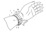
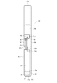
- FIG. 1 is a perspective view showing a configuration of a blood pressure measuring device according to the first embodiment of the present invention.
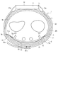
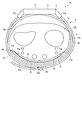
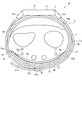
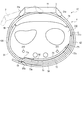
- FIG. 2 is an explanatory view showing a state in which the blood pressure measuring device is worn on the wrist.
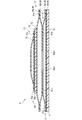
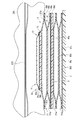
- FIG. 3 is a cross-sectional view showing the configuration of the carla and the cuff structure of the blood pressure measuring device.
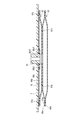
- FIG. 4 is a cross-sectional view showing the configuration of the carla and the cuff structure.
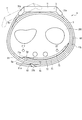
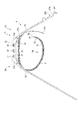
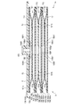
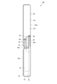
- FIG. 5 is a plan view showing the configuration of the cuff structure.
- FIG. 6 is a plan view showing the configuration of the cuff structure.
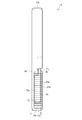
- FIG. 7 is a cross-sectional view showing the configuration of the sensing cuff of the cuff structure.
- FIG. 1 is a perspective view showing a configuration of a blood pressure measuring device according to the first embodiment of the present invention.
- FIG. 2 is an explanatory view showing a state in which the blood pressure measuring device is worn on the wrist.
- FIG. 3 is a
- FIG. 8 is a perspective view showing an example of wearing the blood pressure measuring device on the wrist.
- FIG. 9 is a perspective view showing an example of wearing the blood pressure measuring device on the wrist.
- FIG. 10 is a perspective view showing an example of wearing the blood pressure measuring device on the wrist.
- FIG. 11 is a cross-sectional view schematically showing a state in which the blood pressure measuring device is attached to the wrist.
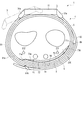
- FIG. 12 is an explanatory view showing a state in which the blood pressure measuring device is worn on the wrist.
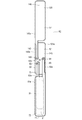
- FIG. 13 is a side view showing the configuration of the blood pressure measuring device according to the second embodiment of the present invention.
- FIG. 14 is an explanatory view showing a state in which the blood pressure measuring device is worn on the wrist.
- FIG. 15 is a cross-sectional view showing the structure of the cuff structure and the carla of the blood pressure measuring device.
- FIG. 16 is a plan view showing the configuration of the cuff structure.
- FIG. 17 is a plan view showing the configuration of the cuff structure.
- FIG. 18 is an explanatory view showing a state in which the blood pressure measuring device is worn on the wrist.
- FIG. 19 is an explanatory view showing a state in which the blood pressure measuring device according to the third embodiment of the present invention is worn on the wrist.
- FIG. 20 is a plan view showing the configuration of the cuff structure of the blood pressure measuring device.
- FIG. 21 is a plan view showing the configuration of the cuff structure.
- FIG. 22 is an explanatory view showing a state in which the blood pressure measuring device according to the fourth embodiment of the present invention is worn on the wrist.
- FIG. 23 is a plan view showing the configuration of the cuff structure of the blood pressure measuring device.
- FIG. 24 is an explanatory view showing a state in which the blood pressure measuring device is worn on the wrist.
- FIG. 25 is an explanatory view showing a state in which the blood pressure measuring device according to the modified example of the first to fourth embodiments is worn on the wrist.
- FIG. 26 is an explanatory view showing a state in which the blood pressure measuring device is worn on the wrist.
- FIG. 27 is an explanatory view showing a state in which the blood pressure measuring device according to the modified example of the first to fourth embodiments is worn on the wrist.
- FIG. 28 is an explanatory view showing a state in which the blood pressure measuring device according to the modified example of the first to fourth embodiments is worn on the wrist.
- FIG. 29 is an explanatory view showing a state in which
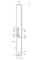
- FIG. 1 is a perspective view showing the configuration of the blood pressure measuring device 1 according to the first embodiment of the present invention.
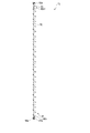
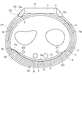
- FIG. 2 is an explanatory view showing a state in which the blood pressure measuring device 1 is attached to the wrist 200.
- FIG. 2 shows a state in which the blood pressure measuring device 1 is attached to the wrist 200 having the shortest circumference, which is assumed to be the circumference of the wrist 200, among the wrists 200 of a plurality of users set to be used by the blood pressure measuring device 1.
- An example is shown.
- the cuff structure 6 shown in FIG. 2 is in an expanded state.
- FIG. 3 is a cross-sectional view showing the configuration of the carla 5 and the cuff structure 6 of the blood pressure measuring device 1.
- FIG. 4 is a cross-sectional view showing the configuration of the carla 5 and the cuff structure 6 of the blood pressure measuring device 1.
- FIG. 5 is a plan view showing a surface of the cuff structure 6 of the blood pressure measuring device 1 fixed to the inner peripheral surface of the carla 5.
- FIG. 6 is a plan view showing a surface of the structure of the cuff structure 6 fixed to the inner peripheral surface 5c of the carla 5.
- FIG. 7 is a cross-sectional view showing the configuration of the pressing cuff 71 of the cuff structure 6.
- 8 to 10 are perspective views showing an example in which the blood pressure measuring device 1 is attached to the wrist 200.
- FIG. 11 is a cross-sectional view schematically showing a state in which the blood pressure measuring device 1 is attached to the wrist 200.
- FIG. 12 is an explanatory view showing a state in which the blood pressure measuring device 1 is attached to the wrist 200.
- FIG. 12 shows a state in which the blood pressure measuring device 1 is attached to the wrist 200 having the longest circumference of which the circumference of the wrist 200 is expected to be among the wrists 200 of a plurality of users who are assumed to use the blood pressure measuring device 1. An example is shown.
- the cuff structure 6 shown in FIG. 12 is in an expanded state.
- the blood pressure measuring device 1 includes a device main body 3, a belt 4 for fixing the device main body 3 to the wrist 200, a carla 5 arranged between the belt 4 and the wrist 200, and a cuff.
- the structure 6 and the like are provided.
- the device main body 3 includes, for example, a case 11, a display unit 12, and an operation unit 13. Further, the apparatus main body 3 includes a pump for expanding the cuff structure 6, a flow path portion for fluidly connecting the pump and the cuff structure 6, and a control board in the case 11.
- the case 11 includes an outer case 31 and a windshield 32 that covers an opening on the side opposite to the wrist 200 side of the outer case 31.
- the outer case 31 is formed in a cylindrical shape.
- the outer case 31 includes a pair of lugs 31a provided at symmetrical positions in the circumferential direction of the outer peripheral surface, and a spring rod 31b provided between the two pairs of lugs 31a, respectively.
- the windshield 32 is, for example, a circular glass plate.
- the display unit 12 is arranged directly below the windshield 32. As shown in FIG. 1, the display unit 12 is electrically connected to the control board.
- the display unit 12 is, for example, a liquid crystal display or an organic electroluminescence display.
- the display unit 12 displays various information including the date and time, the blood pressure value such as the systolic blood pressure and the diastolic blood pressure, and the measurement result such as the heart rate.
- the operation unit 13 is configured so that commands from the user can be input.
- the operation unit 13 includes a plurality of buttons 41 provided on the case 11 and a sensor for detecting the operation of the buttons 41.
- the buttons 41 are provided.
- the belt 4 includes a first belt 61 provided on one pair of lugs 31a and a spring rod 31b, and a second belt 62 provided on the other pair of lugs 31a and a spring rod 31b.
- the belt 4 is wrapped around the wrist 200 via the carla 5.
- the first belt 61 is a so-called parent and is configured in a band shape that can be connected to the second belt 62.
- the first belt 61 has a belt portion 61a and a buckle 61b.
- the belt portion 61a is formed in a band shape.
- the belt portion 61a is made of an elastically deformable resin material.
- the buckle 61b is provided at the other end of the belt portion 61a.
- the buckle 61b has a rectangular frame-shaped frame-shaped body 61e and a stick 61f rotatably attached to the frame-shaped body 61e.
- the second belt 62 is a so-called sword tip, and is configured in a band shape having a width that can be inserted into the frame-shaped body 61e.
- the second belt 62 is made of an elastically deformable resin material. Further, the second belt 62 has a plurality of small holes 62a into which the stick 61f is inserted. One end of the second belt 62 is supported by the other spring rod 31b.
- the first belt 61 and the second belt 62 are integrally connected by inserting the second belt 62 into the frame-shaped body 61e and inserting the rod 61f attached to the small hole 62a. Then, together with the outer case 31, it becomes an annular shape that follows the circumferential direction of the wrist 200.
- the belt 4 forms an annular shape that follows the circumferential direction of the wrist 200, thereby pressing the carla 5 and elastically deforming the carla 5 so as to follow the circumferential direction of the wrist 200 of the wearer of the blood pressure measuring device 1.
- the carla 5 is formed in a band shape that curves along the circumferential direction of the wrist 200.
- the carla 5 is formed so that one end 5a and the other end 5b are separated from each other.
- the outer peripheral surface on the other end 5b side is fixed to the apparatus main body 3.
- One end 5a is one end of the wrist 200 on the palm side.
- the other end 5b is one end of the wrist 200 on the back side of the hand.
- the carla 5 is made of, for example, a resin material.
- the carla 5 is formed so that the length from the device main body 3 to the other end 5b is shorter than the length from the device main body 3 to one end 5a.
- the short side from the device main body 3 to the other end 5b is arranged on the back side of the wrist 200.
- the longitudinal side of the carla 5 from the device main body 3 to one end 5a extends from the back side of the wrist 200 to the palm side of the wrist 200 through one side.
- Such a carla 5 is fixed to the outer case 31 with one end 5a and the other end 5b facing the first belt 61 of the belt 4.
- the carla 5 has a hardness having flexibility and shape retention.
- “flexibility” means that the shape is deformed in the radial direction when an external force of the belt 4 is applied to the carla 5.
- flexibility means that when the carla 5 is pressed by the belt 4, the shape of the side view is close to the wrist 200, follows the shape of the wrist 200, or follows the shape of the wrist 200. It means to transform.
- the shape-retaining property means that the carla 5 can maintain a preformed shape when no external force is applied.
- the shape retention means that in the present embodiment, the shape of the carla 5 can be maintained in a shape that is curved along the circumferential direction of the wrist 200.
- the cuff structure 6 is arranged on the inner peripheral surface of the carla 5.
- the carla 5 holds a part of the cuff structure 6 along the shape of the inner peripheral surface 5c of the carla 5.
- the carla 5 holds the cuff structure 6 by fixing the cuff structure 6 by a joint layer 75 provided between the carla 5 and the cuff structure 6.
- the bonding layer 75 is an adhesive or double-sided tape.
- the cuff structure 6 includes a pressing cuff (cuff) 71, a back plate 72, and a sensing cuff 73.
- the pressing cuff 71 is an example of a cuff arranged between the sensing cuff 73 and the carla 5 and in the region where the sensing cuff 73 exists on the outer peripheral surface 5d of the carla 5.
- the cuff structure 6 includes a bonding layer 75 that joins each structure and the carla 5 and the pressing cuff 71.
- the pressing cuff 71, the back plate 72, and the sensing cuff 73 are laminated and arranged on the carla 5.
- the pressing cuff 71 is fixed to the inner peripheral surface 5c of the carla 5.
- the back plate 72 is fixed to the inner peripheral surface of the wrist 200 of the pressing cuff 71 on the palm side from the inner peripheral surface of the pressing cuff 71 toward the wrist 200 side.
- the sensing cuff 73 is fixed to the inner peripheral surface of the back plate 72 on the palm side.
- Each member of the cuff structure 6 is fixed to a member adjacent to each other in the stacking direction by a joint layer 75.
- the pressing cuff 71 is fluidly connected to the pump via the flow path portion.
- the pressing cuff 71 is formed in a band shape extending in one direction. A part of the pressing cuff 71 is fixed to the inner peripheral surface of the carla 5 by the joining layer 75.
- the pressing cuff 71 may be attached to the wrist 200 having any circumference from the assumed shortest circumference to the assumed longest circumference of the wrist 200, even when the blood pressure measuring device 1 is attached to the wrist 200.
- a part of the pressing cuff 71 is set to a length located in the region where the sensing cuff 73 exists on the outer peripheral surface 5d of the carla 5.
- the pressing cuff 71 is configured to protrude beyond the other end 5b of the carla 5 in the circumferential direction of the carla 5.
- the portion of the pressing cuff 71 that protrudes beyond the other end 5b of the carla 5 in the circumferential direction is formed by at least the sensing cuff 73 on the outer peripheral surface 5d of the carla 5 with the blood pressure measuring device 1 attached to the wrist 200. At least placed in the existing area.
- the length of the portion of the pressing cuff 71 that protrudes beyond the other end 5b of the carla 5 is the wrist of any circumference from the assumed shortest circumference of the wrist 200 to the assumed longest circumference. Even when the blood pressure measuring device 1 is attached to the 200, the pressing cuff 71 is set to a length located at least in the region where the sensing cuff 73 on the outer peripheral surface 5d of the carla 5 exists.
- the wrist 200 having the shortest expected circumference of the wrist 200 is, as shown in FIG. 2, the circumference of the wrist 200 among the wrists 200 of a plurality of users set to be used by the blood pressure measuring device 1.
- the wrist 200 has the shortest length.
- the wrist 200 having the longest expected circumference is the wrist 200 having the longest circumference among the wrists 200 of a plurality of users assumed to be used by the blood pressure measuring device 1.
- the length of the portion of the pressing cuff 71 protruding from the other end 5b of the carla 5 is such that the blood pressure measuring device 1 is attached to the wrist 200 having the shortest expected peripheral length of the wrist 200, and the device body 3 is attached. The length is set so that it does not touch.
- One end 71a of the pressing cuff 71 is arranged near, for example, one end 5a located on the palm side of the wrist 200 on the inner peripheral surface 5c of the carla 5.
- the pressing cuff 71 has an insertion portion 71c capable of arranging a part of the sensing cuff 73 in the longitudinal direction of the pressing cuff 71, for example, in the middle abdomen.
- the insertion portion 71c is formed, for example, in a shape in which a part of an edge portion along the longitudinal direction of the pressing cuff 71 is recessed in the lateral direction of the pressing cuff 71.
- the insertion portion 71c is configured so that the sensing cuff 73 can be passed from the inner peripheral surface side of the pressing cuff 71 to the carla 5 side.
- the pressing cuff 71 includes, for example, a plurality of air bags 81 and a connecting portion 84 provided in the air bag 81 facing the carla 5.
- the plurality of air bags 81 are, for example, two air bags 81.
- Such a pressing cuff 71 is configured by integrally welding a plurality of sheet members 86.
- the connecting portion 84 is connected to the flow path portion. By connecting the connecting portion 84 to the flow path portion, the pressing cuff 71 is fluidly connected to the pump.
- the air bag 81 is a bag-shaped structure, and in the present embodiment, the blood pressure measuring device 1 has a configuration in which air is used by a pump.
- the bag-shaped structure may be a fluid bag that expands with the fluid.
- the plurality of air bags 81 are laminated and fluidly communicate with each other in the stacking direction.
- the air bag 81 is formed in the shape of a rectangular bag that is long in one direction. Further, the width of the air bag 81 in the lateral direction is set to be the same as the width of the carla 5 in the lateral direction.
- the air bag 81 is formed by, for example, combining two sheet members 86 and welding them by heat in a rectangular frame shape long in one direction as shown in FIGS. 3 to 6A.
- two air bags 81 are welded by heat and combined integrally, or after welding the opposing sheet members 86 of the adjacent air bags 81 to each other, these facing sheets are formed.
- Each member 86 is formed by welding a sheet member 86 constituting the air bag 81.
- the two-layer air bag 81 fluidly communicates with each other through openings provided in the sheet members 86 facing each other. Further, in the two-layer air bag 81, the opposing sheet members 86 are bridge-welded to each other in a four-sided frame shape smaller than the welded portion 81a located on the outer peripheral edge, and the bridge welded portion 81b surrounds a plurality of openings. Adjacent air bags 81 are integrally formed. Then, the two-layer air bag 81 is fluidly communicated inside the bridge welding portion 81b.
- the bridge welding and the bridge of the bridge welding portion 81b mean that the adjacent air bags 81 are integrally joined.
- connection portion 84 is, for example, a nipple.
- the connection portion 84 is connected to the flow path portion of the apparatus main body 3.
- the connecting portion 84 is provided, for example, in a portion of the air bag 81 arranged adjacent to the carla 5 facing the device main body 3.
- the tip of the connecting portion 84 is exposed from the seat member 106 facing the carla 5 among the two seat members 86 constituting the air bag 81.
- the connecting portion 84 is connected to the flow path portion.
- the pressing cuff 71 is a second sheet member constituting the first sheet member 86a, the first sheet member 86a, and the first air bag 81 from the wrist 200 side.
- the 86b, the third sheet member 86c integrally joined with the second sheet member 86b, the third sheet member 86c, the second layer air bag 81, and the fourth sheet member 86d constituting the flow path body 83 are attached. Be prepared.
- the pressing cuff 71 is integrally formed by joining adjacent sheet members 86 by heat welding.
- the first sheet member 86a and the second sheet member 86b are formed in the same rectangular shape as the air bag 81, and the peripheral edges of the four sides are welded to form the air bag 81.
- the second seat member 86b and the third seat member 86c are arranged so as to face each other, and each has a plurality of openings 86b1 and 86c1 for fluidly communicating the two air bags 81.
- the second sheet member 86b and the third sheet member 86c are integrally joined by being welded around the plurality of openings 86b1 and 86c1 in a four-sided frame shape smaller than the four sides by which the air bag 81 is welded. Will be done.
- the third seat member 86c is configured, for example, in a shape that allows the air bag 81 to be configured.
- the fourth seat member 86d is configured, for example, in a shape capable of forming the air bag 81. Further, the fourth seat member 86d has, for example, a hole 86d1 into which the tip of the connecting portion 84 can be inserted.
- the third sheet member 86c and the fourth sheet member 86d are arranged so as to face each other, are welded by heat along the peripheral shape of the air bag 81, and are cut into a predetermined shape to form the air bag 81.
- a connecting portion 84 is arranged in the hole portion 86d1, and the periphery of the hole portion 86d1 is welded to the connecting portion 84 by heat. Further, the fourth seat member 86d is joined to the inner peripheral surface 5c of the carla 5, and the third seat member 86c is joined to the carla 5 via the joining layer 75.
- the back plate 72 is formed in the shape of a plate that is long in one direction.
- One end 72b of the back plate 72 in the longitudinal direction is arranged near, for example, one end 71a of the pressing cuff 71.
- the back plate 72 is attached to the outer surface of the first sheet member 86a of the pressing cuff 71 by the joint layer 75.
- the back plate 72 has shape followability.
- the shape followability means a function in which the back plate 72 can be deformed so as to imitate the shape of the contacted portion of the wrist 200 to be arranged, and the back plate 72 faces the contacted portion of the wrist 200.
- the area of the wrist 200, where contact includes both direct contact and indirect contact via the sensing cuff 73.
- the back plate 72 has a plurality of grooves 72a extending in a direction orthogonal to the longitudinal direction on both main surfaces of the back plate 72.
- a plurality of grooves 72a are provided on both main surfaces of the back plate 72.
- the plurality of grooves 72a provided on both main surfaces face each other in the thickness direction of the back plate 72. Further, the plurality of grooves 72a are arranged at equal intervals in the longitudinal direction of the back plate 72.
- the back plate 72 Since the portion of the back plate 72 having the plurality of grooves 72a is thinner than the portion having the plurality of grooves 72a, the portion having the plurality of grooves 72a is easily deformed. Therefore, the back plate 72 follows the shape of the wrist 200. It is deformed and has a shape-following property that extends in the circumferential direction of the wrist 200.
- the back plate 72 is formed to have a length that covers the palm side of the wrist 200.
- the back plate 72 transmits the pressing force from the pressing cuff 71 to the main surface of the sensing cuff 73 on the back plate 72 side while following the shape of the wrist 200.
- the sensing cuff 73 is fluidly connected to the pump via the flow path portion.
- the sensing cuff 73 is fixed to the main surface of the back plate 72 on the wrist 200 side by the joining layer 75.
- the length of the sensing cuff 73 in the longitudinal direction is relative to the wrist 200 having any circumference from the assumed shortest circumference to the assumed longest circumference of the wrist 200. However, the length is set so as to contact the region where at least one of the radial artery 211 and the ulnar artery 212, which are the arteries 210 of the wrist 200, is present.
- the sensing cuff 73 is formed, for example, in the longitudinal direction and the width direction of the back plate 72, having the same shape as the back plate 72 or a shape smaller than the back plate 72.
- the sensing cuff 73 expands to compress the area of the wrist 200 on the palm side of the artery 210.
- the sensing cuff 73 is pressed toward the wrist 200 side via the back plate 72 by the expanded pressing cuff 71.
- the length of the sensing cuff 73 along the longitudinal direction is, for example, the length of contact with the region where the radial artery 211 and the ulnar artery 212 exist with respect to the wrist 200 having the shortest circumference as shown in FIG.
- the length is set so that the wrist 200 having the longest circumference is in contact with the region where the radial artery 211 or the ulnar artery 212 exists.
- the sensing cuff 73 is set to have substantially the same length as the length from the radial artery 211 to the ulnar artery 212 in the circumferential direction of the wrist 200 having the shortest peripheral length.
- the sensing cuff 73 includes, for example, one air bag 91, a flow path body 92 communicating with the air bag 91, and a connecting portion 93 provided at the tip of the flow path body 92. ,including.
- one main surface of the air bag 91 is fixed to the back plate 72.
- the sensing cuff 73 is joined to the main surface of the back plate 72 on the wrist 200 side by a joining layer 75.
- Such a sensing cuff 73 is configured by integrally welding two sheet members 96.
- the air bag 91 is a bag-shaped structure, and in the present embodiment, the blood pressure measuring device 1 has a configuration in which air is used by a pump.
- the bag-shaped structure may be a fluid bag that expands with the fluid.
- the air bag 91 is formed in a rectangular shape that is long in one direction.
- the air bag 91 is configured by, for example, combining two sheet members 96 long in one direction and welding them in a rectangular frame shape long in one direction by heat as shown in FIGS. 5 to 7 to show the welding portion 91a. NS.
- the flow path body 92 is integrally provided on a part of one edge of the air bag 91 in the longitudinal direction.
- the flow path body 92 is provided at an end portion of the air bag 91 near the device main body 3.
- the flow path body 92 is formed in a width smaller than the width in the lateral direction of the air bag 91 and is formed in a long shape in one direction, and the tip is formed in a circular shape.
- the flow path body 92 has a connecting portion 93 at the tip thereof.
- the flow path body 92 is connected to the flow path portion 15 via the connection portion 93, and constitutes a flow path between the flow path portion 15 of the apparatus main body 3 and the air bag 91.
- a part of the sheet member 96 adjacent to the region constituting the air bag 91 of the sheet member 96 is formed into a long frame shape in one direction. It is composed of welding by heat.
- a part of such a flow path body 92 is arranged, for example, from the inner peripheral surface side of the pressing cuff 71 to the carla 5 side through the insertion portion 71c of the pressing cuff 71.
- the air bag 91 is configured such that a part of the welding portion 91a that welds the two sheet members 96 in a rectangular frame shape is non-welded and is continuous with the welding portion 92a that constitutes the flow path body 92.
- the air bag 91 and the flow path body 92 are fluidly communicated with each other.
- connection portion 93 is, for example, a nipple.
- the connecting portion 93 is provided at the tip of the flow path body 92. Further, the tip of the connecting portion 93 is exposed to the outside from the seat member 96 facing the carla 5 and the back plate 72 among the two seat members 96 constituting the flow path body 92.
- the connecting portion 93 is connected to the flow path portion.
- the sensing cuff 73 includes a fifth seat member 96a and a sixth seat member 96b from the wrist 200 side.
- the sensing cuff 73 is configured by joining adjacent sheet members 96 by heat welding.
- the fifth seat member 96a and the sixth seat member 96b are configured so that the air bag 91 and the flow path body 92 can be configured.
- the fifth sheet member 96a and the sixth sheet member 96b are arranged so as to face each other, and along the peripheral shape of the air bag 91 and the flow path body 92 so that the air bag 91 and the flow path body 92 fluidly communicate with each other.
- the air bag 91 and the flow path body 92 are formed by being welded by heat and cut into a predetermined shape.
- the sixth sheet member 96b has, for example, a hole 96b1 into which the tip of the connecting portion 93 can be inserted.
- a connecting portion 93 is arranged in the hole portion 96b1, and the periphery of the hole portion 96b1 is welded to the connecting portion 93 by heat.
- the sixth seat member 96b is joined to the inner peripheral surface of the back plate 72 via the joining layer 75.
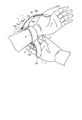
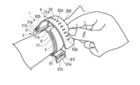
- 8 to 10 show an example in which the user wears the blood pressure measuring device 1 on the wrist 200.
- the user inserts the wrist 200 into the carla 5 as shown in FIG. 8, for example.
- the portion of the pressing cuff 71 protruding from the other end 5b of the carla 5 may hang downward depending on, for example, the posture of the wrist 200.
- the user moves the portion of the pressing cuff 71 protruding from the other end 5b of the carla 5 to the outer peripheral surface 5d side of the carla 5. Then, the user passes the second belt 62 through the frame-shaped body 61e of the buckle 61b of the first belt 61 by a hand opposite to the hand on which the blood pressure measuring device 1 is arranged. Next, the user pulls the second belt 62, brings the member on the inner peripheral surface 5c side of the carla 5, that is, the cuff structure 6 into close contact with the wrist 200, and inserts the rod 61f attached to the small hole 62a.
- the portion of the pressing cuff 71 protruding from the other end 5b of the carla 5 is arranged in the region where at least the sensing cuff 73 exists on the outer peripheral surface 5d of the carla 5, and is sandwiched by the carla 5 and the belt 4.
- the blood pressure measuring device 1 is attached to the wrist 200.
- the sensing cuff 73 is a wrist. It contacts 200 radial arteries 211 and ulnar arteries 212. Further, a part of the pressing cuff 71 protruding from the other end 5b of the carla 5 is arranged in the region where the sensing cuff 73 exists on the outer peripheral surface 5d of the carla 5.
- the sensing cuff 73 is pressed toward the wrist 200 by the pressing cuff 71 arranged between the sensing cuff 73 and the carla 5. Further, the sensing cuff 73 is pressed toward the wrist 200 by the pressing cuff 71 arranged in the region where the sensing cuff 73 exists on the outer peripheral surface 5d of the carla 5. Therefore, since the pressing force for pressing the sensing cuff 73 toward the wrist 200 can be increased, the sensing cuff 73 is brought into close contact with the region where the radial artery 211 and the ulnar artery 212 of the wrist 200 exist.
- the position of the sensing cuff 73 with respect to the wrist 200 is the shortest expected circumference. It shifts to the radial artery 211 side with respect to the wrist 200.
- the sensing cuff 73 has a length that contacts the region where the radial artery 211 exists in a state where the blood pressure measuring device 1 is attached to the wrist 200 having the longest expected peripheral length of the wrist 200. Therefore, the sensing cuff 73 is arranged in the region where the radial artery 211 of the wrist 200 exists.
- a portion of the pressing cuff 71 that protrudes from the other end 5b of the carla 5 is arranged on the outer peripheral surface 5d of the carla 5 in at least a region where the sensing cuff 73 exists.
- the sensing cuff 73 is pressed toward the wrist 200 by the pressing cuff 71 arranged between the carla 5 and the sensing cuff 73. Further, the sensing cuff 73 is pressed toward the wrist 200 by the pressing cuff 71 arranged in the region where the sensing cuff 73 exists on the outer peripheral surface 5d of the carla 5. Therefore, since the pressing force for pressing the sensing cuff 73 against the wrist 200 can be increased, the sensing cuff 73 is brought into close contact with the region where the artery 210 of the wrist 200 exists.
- FIG. 1 When the blood pressure measuring device 1 is attached to the wrist 200 having a relatively long circumference of the wrist 200, for example, when the blood pressure measuring device 1 is attached to the wrist 200 having the longest expected circumference of the wrist 200, FIG.
- the position of the wrist 200 of the blood pressure measuring device 1 in the circumferential direction may be adjusted so that the device main body 3 is indicated by a two-point chain line.
- the position of the wrist 200 of the blood pressure measuring device 1 in the circumferential direction may be adjusted so that the central portion of the sensing cuff 73 in the circumferential direction faces the radial artery 211.
- the pressing cuff 71 is the outer peripheral surface of the carla 5 even when the blood pressure measuring device 1 is attached to the wrist 200 having any of the assumed shortest perimeter to the longest perimeter of the wrist 200. It has a length facing at least the region of 5d where the sensing cuff 73 resides.
- the sensing cuff 73 can be brought into close contact with the region where the artery of the wrist 200 exists for any of the assumed shortest to longest perimeters of the wrist 200. ..
- a pressing cuff 71 is used as a cuff arranged between the sensing cuff 73 and the carla 5 and a cuff arranged in the area where the sensing cuff 73 of the carla 5 exists. In this way, by using one cuff, it is possible to prevent an increase in the number of parts of the blood pressure measuring device 1.
- the sensing cuff can be brought into close contact with the region where the artery of the wrist 200 exists.
- FIGS. 13 to 18 an example of the blood pressure measuring device 1A according to the second embodiment of the present invention will be illustrated below with reference to FIGS. 13 to 18.
- the same configurations as those in the first embodiment are designated by the same reference numerals as those in the first embodiment, and the description thereof will be omitted.
- FIG. 13 is a side view showing the configuration of the blood pressure measuring device 1A.
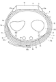
- FIG. 14 is an explanatory view showing a state in which the blood pressure measuring device 1A is attached to the wrist 200.
- the wrist 200 shown in FIG. 14 is the wrist 200 of the user having the shortest peripheral length of the wrist 200 among the plurality of users set as the target of use of the blood pressure measuring device 1.
- the cuff structure 6A shown in FIG. 14 is in an expanded state.
- FIG. 15 is a cross-sectional view showing the configuration of the cuff structure 6A and the carla 5.
- FIG. 16 is a plan view showing the configuration of the surface of the cuff structure 6A opposite to the surface fixed to the carla 5.
- FIG. 17 is a plan view showing the configuration of the surface of the cuff structure 6A on the side fixed to the carla 5.
- FIG. 18 is an explanatory view showing a state in which the blood pressure measuring device 1A is attached to the wrist 200.
- the wrist 200 shown in FIG. 18 is the wrist 200 having the longest expected circumference of the wrist 200 among the wrists 200 of a plurality of users set to be used by the blood pressure measuring device 1A.
- the cuff structure 6A shown in FIG. 18 is in an expanded state.
- the blood pressure measuring device 1A is an electronic blood pressure measuring device worn on a living body.
- the blood pressure measuring device 1A will be described using an electronic blood pressure measuring device having the aspect of a wearable device worn on the wrist 200 of a living body.
- the blood pressure measuring device 1A includes a device main body 3A, a belt 4, a carla 5, and a cuff structure 6A.
- the cuff structure 6A is arranged on the inner peripheral surface of the carla 5. Then, the carla 5 holds the cuff structure 6A along the shape of the inner peripheral surface 5c of the carla 5. For example, the cuff structure 6A is held by fixing the cuff structure 6A by the joint layer 75 provided between the carla 5 and the cuff structure 6A.
- the cuff structure 6A includes a pressing cuff 71A (first cuff), a back plate 72, a sensing cuff 73, and a tension cuff (second cuff). 74 and.
- the cuff structure 6A includes a bonding layer 75 that joins each structure and the carla 5 and the pressing cuff 71A.
- the pressing cuff 71A is fluidly connected to the pump via the flow path portion.
- the pressing cuff 71A presses the back plate 72 and the sensing cuff 73 toward the wrist 200 by expanding.
- the pressing cuff 71A is formed in a band shape extending in one direction.
- the pressing cuff 71A is fixed to the inner peripheral surface of the carla 5 by the joining layer 75.
- One end 71a of the pressing cuff 71A is arranged in the vicinity of one end 5a of the carla 5 located on the palm side of the wrist 200.
- the pressing cuff 71A has a configuration in which the pressing cuff 71 of the first embodiment does not include a portion of the outer peripheral surface 5d of the carla 5 where at least the sensing cuff 73 exists.
- the pressing cuff 71A is not configured to protrude beyond the other end 5b of the carla 5.
- the pressing cuff 71A includes a plurality of air bags 81, a flow path body 83 communicating with the air bag 81, and a connecting portion 84 provided at the tip of the flow path body 83.
- the plurality of air bags 81 are, for example, two-layer air bags 81.
- the two-layer air bag 81 of the pressing cuff 71A has a size facing the region of the inner peripheral surface 5c of the carla 5 facing the palm side of the wrist 200.
- the flow path body 83 is integrally provided on a part of the edge portion at one end in the longitudinal direction of one air bag 81, for example, the air bag 81 adjacent to the carla 5.
- the flow path body 83 is provided at an end portion of the air bag 81 near the device main body 3.
- the flow path body 83 is formed in a width smaller than the width in the lateral direction of the air bag 81 and is formed in a long shape in one direction, and the tip is formed in a circular shape.
- the flow path body 83 has a connecting portion 84 at the tip thereof.
- a part of the sheet member 86 adjacent to the region forming the air bag 81 of the sheet member 86 is formed into a long frame shape in one direction. It is composed of welding by heat.
- the air bag 81 provided with the flow path body 83, a part of the welding portion 81a for welding the two sheet members 86 in a rectangular frame shape is non-welded and is continuous with the welding portion 83a constituting the flow path body 83.
- the air bag 81 fluidly communicates with the flow path body 83.
- the connecting portion 84 is connected to the flow path portion.
- the tension cuff 74 is fluidly connected to the pump via the flow path portion.
- the tension cuff 74 is fixed to the back side of the wrist 200 of the carla 5. Further, at least a part of the tension cuff 74 protrudes from the other end 5b of the carla 5 and is arranged in a region where the sensing cuff 73 exists on the outer peripheral surface 5d of the carla 5 with the blood pressure measuring device 1 attached.
- the tension cuff 74 pulls the belt 4 and the carla 5 toward the back of the wrist 200 by pressing the carla 5 so as to be separated from the wrist 200 by expanding.
- the tension cuff 74 includes, for example, a plurality of air bags 101 and a connecting portion 103 provided in the air bag 101 facing the carla 5.
- the plurality of air bags 101 are, for example, six-layer air bags 101.
- Such a tension cuff 74 is configured by integrally welding a plurality of sheet members 106. Further, the tension cuff 74 is fixed to the back side of the wrist 200 of the carla 5. That is, the flow path body 83 of the pressing cuff 71A and the flow path body 92 of the sensing cuff 73 are arranged between the back side of the wrist 200 of the carla 5 and the tension cuff 74.
- the tension cuff 74 has the thickness at the time of expansion in the expansion direction, in the present embodiment, in the direction opposite to the carla 5 and the wrist 200, the thickness at the time of expansion of the pressing cuff 71A in the expansion direction, and the sensing.
- the cuff 73 is thicker than the thickness at the time of expansion in the expansion direction. That is, the air bag 101 of the tension cuff 74 has a layer structure larger than that of the air bag 81A of the pressing cuff 71A and the air bag 91 of the sensing cuff 73, and the thickness when expanded from the carla 5 toward the wrist 200 is increased. It is thicker than the pressing cuff 71A and the sensing cuff 73.
- the tension cuff 74 including the six-layer air bag 101 is composed of two layers that are integrally combined by being heat-welded to the first outer layer 111 and the first outer layer 111 composed of one air bag 101.
- a second outer layer 114 composed of one air bag 101 that is heat-welded to the layer 113 and integrally combined is provided.
- the air bag 101 is a bag-shaped structure, and in the present embodiment, the blood pressure measuring device 1A has a configuration in which air is used by a pump.
- the bag-shaped structure may be a fluid bag that expands with the fluid.
- the plurality of air bags 101 are laminated and fluidly communicate with each other in the stacking direction.
- the air bag 101 is formed in the shape of a rectangular bag that is long in one direction. Further, the width of the air bag 101 in the lateral direction is set to be the same as the width of the carla 5 in the lateral direction.
- the air bag 101 is formed by, for example, combining two sheet members 106 and welding them in a rectangular frame shape long in one direction by heat as shown in FIGS. 16 and 17 as shown by the welding portion 101a.
- the six-layer air bag 101 fluidly communicates with each other through openings provided in the sheet members 106 facing each other.
- the six-layer air bag 101 is a sheet in which the first outer layer 111 and the first intermediate layer 112, the first intermediate layer 112 and the second intermediate layer 113, and the second intermediate layer 113 and the second outer layer 114 face each other.
- the members 106 are bridge-welded to each other in a four-sided frame shape smaller than the welding portion 81a located on the outer peripheral edge, and the bridge welding portions 101b surround a plurality of openings to integrally form adjacent air bags 101. It communicates fluidly inside the bridge welded portion 101b.
- the first outer layer 111 is formed by one air bag 101 arranged on the wrist 200 side.
- the first outer layer 111 constitutes the first layer air bag 101 from the wrist 200 side of the six layers air bag 101.
- the first intermediate layer 112 is laminated on the first outer layer 111.
- the first intermediate layer 112 is formed by a two-layer air bag 101.
- the first intermediate layer 112 constitutes the second layer and the third layer of the air bag 101 from the wrist 200 side among the six layers of the air bag 101.
- the first intermediate layer 112 is formed by integrally welding two layers of air bags 101 at the outer peripheral edge. In other words, the first intermediate layer 112 is formed by integrally welding four sheet members 106 in the shape of the outer peripheral edge of the air bag 101.
- the second intermediate layer 113 is laminated on the first intermediate layer 112.
- the second intermediate layer 113 is formed by a two-layer air bag 101.
- the second intermediate layer 113 constitutes the fourth layer and the fifth layer of the air bag 101 from the wrist 200 side among the six layers of the air bag 101.
- the second intermediate layer 113 is formed by integrally welding the two layers of air bags 101 at the outer peripheral edge. In other words, the second intermediate layer 113 is formed by integrally welding four sheet members 106 in the shape of the outer peripheral edge of the air bag 101.
- the second outer layer 114 is formed by one air bag 101 arranged on the carla 5 side.
- the second outer layer 114 constitutes the sixth layer air bag 101 from the wrist 200 side of the six layers air bag 101.
- connection portion 103 is, for example, a nipple.
- the connecting portion 103 is provided in the air bag 101 arranged adjacent to the carla 5.
- the tip of the connecting portion 103 is exposed from the seat member 106 facing the carla 5 among the two seat members 106 constituting the air bag 101.
- the connecting portion 103 is connected to the flow path portion.
- the tension cuff 74 has a seventh seat member 106a, an eighth seat member 106b, a ninth seat member 106c, a tenth seat member 106d, and a thirth from the wrist 200 side.
- the seat member 106l and the like are provided.
- the tension cuff 74 is integrally formed by joining adjacent sheet members 106 by heat welding.
- the 7th seat member 106a to the 18th seat member 106l are configured in the same rectangular shape as the air bag 101.
- the seventh seat member 106a and the eighth seat member 106b are welded by heat along the shape of the peripheral edges of the four sides of the air bag 101 to form the first air bag 101 from the wrist 200 side. That is, the 7th seat member 106a and the 8th seat member 106b form the first outer layer 111.
- the eighth sheet member 106b and the ninth sheet member 106c are arranged so as to face each other, and have a plurality of openings 106b1 and 106c1 for fluidly communicating the two air bags 101, respectively. Further, the eighth sheet member 106b and the ninth sheet member 106c are integrally bridge-welded around the plurality of openings 106b1 and 106c1 in a four-sided frame shape smaller than the four sides to which the air bag 101 is welded by heat. Be joined.
- the 9th sheet member 106c and the 10th sheet member 106d are welded by heat along the shape of the peripheral edges of the four sides of the air bag 101 to form the second layer air bag 101 from the wrist 200 side.
- the tenth sheet member 106d and the eleventh sheet member 106e are arranged so as to face each other, and have a plurality of openings 106d1 and 106e1 for fluidly communicating the two air bags 101, respectively.
- the eleventh sheet member 106e and the twelfth sheet member 106f are welded by heat along the shape of the peripheral edges of the four sides of the air bag 101 to form the third layer air bag 101 from the wrist 200 side.
- the ninth sheet member 106c, the tenth sheet member 106d, the eleventh sheet member 106e, and the twelfth sheet member 106f are integrally welded by heat along the shape of the peripheral edges of the four sides of the air bag 101.
- the first intermediate layer 112 in which the air bags 101 of the second layer and the third layer are integrally formed is formed.
- the 12th sheet member 106f and the 13th sheet member 106g are arranged so as to face each other, and have a plurality of openings 106f1 and 106g1 for fluidly communicating the two air bags 101, respectively. Further, the 12th sheet member 106f and the 13th sheet member 106g are integrally bridge-welded around the plurality of openings 106f1 and 106g1 in a four-sided frame shape smaller than the four sides by which the air bag 101 is welded. Be joined.
- the 13th sheet member 106g and the 14th sheet member 106h are welded by heat along the shape of the peripheral edges of the four sides of the air bag 101 to form the fourth layer air bag 101 from the wrist 200 side.
- the 14th sheet member 106h and the 15th sheet member 106i are arranged so as to face each other, and have a plurality of openings 106h1 and 106i1 for fluidly communicating the two air bags 101, respectively.
- the 15th sheet member 106i and the 16th sheet member 106j are welded by heat along the shape of the peripheral edges of the four sides of the air bag 101 to form the fifth layer air bag 101 from the wrist 200 side.
- the 13th sheet member 106g, the 14th sheet member 106h, the 15th sheet member 106i, and the 16th sheet member 106j are integrally welded by heat along the shape of the peripheral edges of the four sides of the air bag 101.
- the second intermediate layer 113 is formed by integrally forming the air bags 101 of the fourth layer and the fifth layer.
- the 16th sheet member 106j and the 17th sheet member 106k are arranged so as to face each other, and have a plurality of openings 106j1 and 106k1 for fluidly communicating the two air bags 101, respectively. Further, the 17th sheet member 106k is configured, for example, in a shape capable of forming the air bag 101.
- the 16th sheet member 106j and the 17th sheet member 106k are integrally joined by heat-bridge welding around the plurality of openings 106j1 and 106k1 in a four-sided frame shape smaller than the four sides to which the air bag 101 is welded. NS.
- the 17th sheet member 106k and the 18th sheet member 106l are welded by heat along the shape of the peripheral edges of the four sides of the air bag 101 and cut into a predetermined shape to form the air bag 101.
- the 18th sheet member 106l has, for example, a hole 106l1 into which the tip of the connecting portion 103 can be inserted.
- the connecting portion 103 is arranged in the hole portion 106l1, and the periphery of the hole portion 106l1 is welded to the connecting portion 103 by heat.
- the 18th sheet member 106l is joined to the inner peripheral surface 5c of the carla 5, and the 17th sheet member 106k is joined to the inner peripheral surface 5c of the carla 5 via the joining layer 75, respectively.
- a part of the protruding portion is the carla 5 even when the blood pressure measuring device 1A is attached to the wrist 200 having any circumference from the assumed shortest circumference to the assumed longest circumference of the wrist 200. It is configured to have a length arranged in the region where the sensing cuff 73 exists on the outer peripheral surface 5d of the above.
- the second outer layer 114 of the tension cuff 74 is formed longer than the other layers of the tension cuff 74 and is assumed from the shortest possible perimeter of the wrist 200.
- the second outer layer 114 is arranged at least in the region where the sensing cuff 73 on the outer peripheral surface 5d of the carla 5 exists, regardless of the circumference of the wrist 200 up to the longest circumference, even when the blood pressure measuring device 1A is attached. ..
- the second outer layer 114 is as shown in FIG. 14 with respect to the wrist 200 having the shortest expected peripheral length of the wrist 200 when the device main body 3A is arranged on the back side of the wrist 200. Has a length extending laterally beyond the sensing cuff 73 and the radial artery 211 to the wrist 200. Further, the second outer layer 114 extends beyond the sensing cuff 73 and the radial artery 211 to the side of the wrist 200, even with respect to the wrist 200 having the longest expected circumference of the wrist 200, as shown in FIG. Has a length.
- the sensing cuff 73 is attached to the wrist 200.
- a part of the second outer layer 114 of the tension cuff 74 is arranged in the region where the sensing cuff 73 of 5d is located on the outer peripheral surface of the carla 5.
- the outer peripheral surface 5d of the carla 5 is pressed by the second outer layer 114 of the tension cuff 74, so that the sensing cuff 73 is pressed toward the wrist 200 side.
- the sensing cuff 73 is pressed by the pressing cuff 71 and the second outer layer 114 of the tension cuff 74, so that the pressing force for pressing the sensing cuff 73 against the wrist 200 can be increased, so that the sensing cuff 73 can be pressed by the wrist 200. It is in close contact with the region where the radial artery 211 and the ulnar artery 212 are located.
- the sensing cuff 73 comes into contact with the region where the radial artery 211 of the wrist 200 exists.
- a part of the second outer layer 114 of the tension cuff 74 is arranged in the region where the sensing cuff 73 exists on the outer peripheral surface 5d of the carla 5.
- the sensing cuff 73 is pressed toward the wrist 200 by the pressing cuff 71.
- the tension cuff 74 is expanded, the outer peripheral surface 5d of the carla 5 is pressed by the second outer layer 114 of the tension cuff 74, so that the sensing cuff 73 is pressed toward the wrist 200 side.
- the sensing cuff 73 is pressed by the pressing cuff 71 and the second outer layer 114 of the tension cuff 74, so that the pressing force for pressing the sensing cuff 73 against the wrist 200 can be increased, so that the sensing cuff 73 can be pressed by the wrist 200. It is in close contact with the area where the radial artery 211 is located.
- FIG. 1A When the blood pressure measuring device 1A is attached to the wrist 200 having a relatively long circumference of the wrist 200, for example, when the blood pressure measuring device 1A is attached to the wrist 200 having the longest expected circumference of the wrist 200, FIG.
- the position of the wrist 200 of the blood pressure measuring device 1A in the circumferential direction may be adjusted so that the device main body 3 is indicated by a two-point chain line.
- the position of the wrist 200 of the blood pressure measuring device 1A in the circumferential direction may be adjusted so that the central portion of the sensing cuff 73 in the circumferential direction faces the radial artery 211.
- the blood pressure measuring device 1A configured as described above includes a pressing cuff 71A as a cuff arranged between the sensing cuff 73 and the carla 5, and is attached to the wrist 200 at least on the outer peripheral surface 5d of the carla 5.
- a tension cuff 74 is provided as a cuff arranged in the region where the 73 exists. Therefore, the sensing cuff 73 can be brought into close contact with the region where the artery 210 of the wrist 200 exists.
- the blood pressure measuring device 1A is attached.
- the outer peripheral surface 5d of the carla 5 has a length facing at least the region where the sensing cuff 73 exists.
- the sensing cuff 73 should be brought into close contact with the region where the artery of the wrist 200 exists for any wrist 200 having a circumference from the assumed shortest circumference to the assumed longest circumference of the wrist 200. Is possible.
- the tension cuff 74 by using the tension cuff 74 as the cuff arranged in the region where at least the sensing cuff 73 exists on the outer peripheral surface 5d of the carla 5, it is possible to prevent an increase in the number of parts of the blood pressure measuring device 1A. ..
- the sensing cuff can be brought into close contact with the region where the artery of the wrist 200 exists.
- the blood pressure measuring device 1B according to the third embodiment of the present invention will be described with reference to FIGS. 19 to 21.
- the same configuration as the first embodiment and the same configuration as the second embodiment will be described with the same reference numerals as those of the first embodiment and the same reference numerals as those of the second embodiment. Omit.
- FIG. 19 is an explanatory view showing a state in which the blood pressure measuring device 1B is attached to the wrist 200.
- the wrist 200 shown in FIG. 19 is the wrist 200 of a plurality of users set to be used by the blood pressure measuring device 1B, in which the circumference of the wrist 200 is assumed to be the shortest.
- the cuff structure 6B shown in FIG. 19 is in an expanded state.
- FIG. 20 is a plan view showing a state in which the structure of the cuff structure 6B is viewed from the wrist 200 side.
- FIG. 21 is a plan view showing a state in which the structure of the cuff structure 6B is viewed from the inner peripheral surface 5c side of the carla 5.
- the blood pressure measuring device 1B includes a device main body 3, a belt 4, a carla 5, and a cuff structure 6B provided on the carla 5.
- the cuff structure 6B is arranged on the inner peripheral surface of the carla 5. Then, the carla 5 holds the cuff structure 6B along the shape of the inner peripheral surface 5c of the carla 5. For example, the carla 5 holds the cuff structure 6B by fixing the cuff structure 6B by a joint layer 75 provided between the carla 5 and the cuff structure 6B.
- the bonding layer 75 is an adhesive or double-sided tape.
- the cuff structure 6B includes a pressing cuff 71B, a back plate 72, a sensing cuff 73, and a tension cuff 74B.
- the pressing cuff 71B is different from the pressing cuff 71 of the first embodiment in that it has an insertion portion 71d for connecting the connecting portion 103 of the tension cuff 74 to the flow path portion.
- the insertion portion 71d is formed in a region of the pressing cuff 71 facing the connecting portion 103.
- Other configurations of the pressing cuff 71B are the same as those of the pressing cuff 71.
- the insertion portion 71d is configured, for example, in a shape in which a part of the edge along the longitudinal direction of the pressing cuff 71 is recessed in the lateral direction toward the edge along the other longitudinal direction.
- the tension cuff 74B has a configuration in which a part of the second outer layer 114 of the tension cuff 74 of the second embodiment is arranged in a region where the sensing cuff 73 exists on the outer peripheral surface 5d of the carla 5. The difference is that the outer layer 114 is formed to have the same length as the other layers. Other configurations of the tension cuff 74B are the same as the tension cuff 74 of the second embodiment.
- the length of the second outer layer 114 of the tension cuff 74B along the circumferential direction of the carla 5 is the same as the length of the first outer layer 111 along the circumferential direction of the carla 5.
- the pressing cuff 71B of the present embodiment has an insertion portion 71d for connecting the connecting portion 103 of the tension cuff 74B to the flow path portion.
- the insertion portion 71d is formed in a region of the pressing cuff 71B facing the connecting portion 103.
- the insertion portion 71d is configured, for example, in a shape in which a part of the edge along the longitudinal direction of the pressing cuff 71B is recessed in the lateral direction toward the edge along the other longitudinal direction.
- the sensing cuff 73 is arranged between the carla 5 and the sensing cuff 73 by expanding the pressing cuff 71B. It can be pressed toward the wrist 200 by the pressing cuff 71B. Further, by pressing the outer peripheral surface 5d of the carla 5 with the pressing cuff 71B, the sensing cuff 73 can be pressed toward the wrist 200 side. Therefore, the same effect as that of the first embodiment can be obtained.
- the blood pressure measuring device 1C according to the fourth embodiment will be described with reference to FIGS. 22 to 24.
- the configuration having the same function as the second embodiment and the configuration having the same function as the third embodiment will be described with the same reference numerals as those of the second embodiment and the third embodiment. Is omitted.
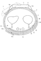
- FIG. 22 is an explanatory view showing a state in which the blood pressure measuring device 1C is attached to the wrist 200.
- FIG. 22 shows a state in which the blood pressure measuring device 1C is attached to the wrist 200 having the shortest circumference among the wrists 200 of a plurality of users assumed to be used by the blood pressure measuring device 1C. An example is shown.
- the cuff structure 6C shown in FIG. 22 is in an expanded state.
- FIG. 23 is a plan view showing a state in which the cuff structure 6C is viewed from the inner peripheral surface 5c side of the carla 5.
- FIG. 24 is an explanatory view showing a state in which the blood pressure measuring device 1C is attached to the wrist 200.
- the blood pressure measuring device 1C is attached to the wrist 200, which is the longest expected circumference of the wrist 200 among the wrists 200 of a plurality of users who are supposed to use the blood pressure measuring device 1C.
- An example of the state is shown.
- the cuff structure 6C shown in FIG. 24 is in an expanded state.
- the blood pressure measuring device 1C includes a device main body 3, a belt 4, a carla 5, and a cuff structure 6C provided on the carla 5.
- the cuff structure 6C is arranged on the inner peripheral surface of the carla 5. Then, the carla 5 holds the cuff structure 6C along the shape of the inner peripheral surface 5c of the carla 5. For example, the carla 5 holds the cuff structure 6C by fixing the cuff structure 6C by a joint layer 75 provided between the carla 5 and the cuff structure 6C.
- the cuff structure 6C includes a pressing cuff 71A (first cuff), a back plate 72, a sensing cuff 73, a tension cuff 74B, and a cuff 130 (second cuff).
- a part of the cuff 130 is arranged in the region where the sensing cuff 73 exists on the outer peripheral surface 5d of the carla 5.
- the cuff 130 is arranged in the circumferential direction of the carla 5 with respect to the tension cuff 74B on the side opposite to the sensing cuff 73.
- a part of the cuff 130 is fixed to the inner peripheral surface 5c of the carla 5 by, for example, the joining layer 75.
- the cuff 130 is configured in a band shape extending along the circumferential direction of the carla 5.
- the cuff 130 projects from the other end 5b of the carla 5 in the circumferential direction of the carla 5.
- the length of the cuff 130 is a part of the cuff 130 regardless of whether the blood pressure measuring device 1C is attached to the wrist 200 having any circumference from the assumed shortest circumference to the assumed longest circumference of the wrist 200. Is set to a length arranged in the region where the sensing cuff 73 exists on the outer peripheral surface 5d of the carla 5.
- the cuff 130 includes, for example, one air bag 141, a flow path body 142 communicating with the air bag 141, and a connecting portion 143 provided at the tip of the flow path body 142.
- one main surface of the air bag 141 is joined to the inner peripheral surface 5c of the carla 5 by, for example, a joining layer 75.
- Such a cuff 130 is configured by integrally welding two sheet members 146.
- the air bag 141 is a bag-shaped structure, and in the present embodiment, the blood pressure measuring device 1C has a configuration in which air is used by a pump.
- the bag-shaped structure may be a fluid bag that expands with the fluid.
- the air bag 141 is configured in a rectangular shape that is long in one direction.
- the air bag 141 is configured by, for example, combining two sheet members 146 long in one direction and welding them in a rectangular frame shape long in one direction by heat as shown in FIG. 23.
- the flow path body 142 is integrally provided on a part of one edge of the air bag 141 in the longitudinal direction.
- the flow path body 142 is provided at an end portion of the air bag 141 near the device main body 3.
- the flow path body 142 is formed in a width smaller than the width in the lateral direction of the air bag 91 and is formed in a long shape in one direction, and the tip is formed in a circular shape.
- the flow path body 142 has a connecting portion 143 at its tip.
- the flow path body 142 is connected to the flow path portion via the connection portion 143, and constitutes a flow path between the flow path portion 15 and the air bag 141.
- a part of the sheet member 146 adjacent to the region constituting the air bag 141 of the sheet member 146 is formed into a long frame shape in one direction. It is composed of welding by heat.
- the air bag 141 is configured such that a part of the welding portion 141a for welding the two sheet members 146 in a rectangular frame shape is non-welded and is continuous with the welding portion 142a constituting the flow path body 142.
- the air bag 141 and the flow path body 142 are fluidly communicated with each other.
- connection portion 143 is, for example, a nipple.
- the connecting portion 143 is provided at the tip of the flow path body 142.
- the connecting portion 143 is connected to the flow path portion.
- the blood pressure measuring device 1C configured in this way has a wrist 200 having any circumference from the assumed shortest circumference to the assumed longest circumference of the wrist 200. Even with the blood pressure measuring device 1C attached, a part of the cuff 130 is arranged on the outer peripheral surface 5d of the carla 5 in the region where at least the sensing cuff 73 exists. A pressing cuff 71A is provided between the sensing cuff 73 and the carla 5.
- the sensing cuff 73 is pressed against the wrist 200.
- the sensing cuff 73 can be brought into close contact with the region of the wrist 200 where the artery exists.
- the pressing force for pressing the sensing cuff 73 against the wrist 200 can be increased, so that the sensing cuff 73 can be applied to the wrist 200. Can be in close contact.
- FIG. 24 The position of the wrist 200 of the blood pressure measuring device 1A in the circumferential direction may be adjusted so that the device main body 3 is indicated by a two-point chain line. In this case, for example, the position of the wrist 200 of the blood pressure measuring device 1 in the circumferential direction may be adjusted so that the central portion of the sensing cuff 73 in the circumferential direction faces the radial artery 211.
- the sensing cuff 73 can be used on the wrist 200 even when the blood pressure measuring device 1C is attached to the wrist 200 having any of the assumed shortest perimeter to the longest perimeter of the wrist 200. It has a length along the carla 5 that contacts the area where the arteries reside.
- the cuff 130 has a length facing the region where the sensing cuff 73 on the outer peripheral surface 5d of the carla 5 exists for any wrist 200 having a circumference from the shortest to the longest expected circumference. Has.
- the sensing cuff 73 can be brought into close contact with the region where the artery of the wrist 200 exists, regardless of the length of the wrist 200 from the shortest to the longest.
- the sensing cuff can be brought into close contact with the region where the artery of the wrist 200 exists.
- one end 5a and the other end 5b of the carla 5 are arranged on one side of the wrist 200, and the other end 5b is on the back side of the hand.
- the configuration in which one end 5a is arranged on the palm side has been described as an example, but the present invention is not limited to this.
- the carla 5 may have a length for arranging the cuff arranged in the region where the sensing cuff 73 on the outer peripheral surface 5d of the carla 5 exists on the inner peripheral surface.
- FIG. 25 is an explanatory view showing a state in which the blood pressure measuring device 1 is attached to the wrist 200.
- the wrist 200 shown in FIG. 25 is the wrist 200 having the shortest perimeter expected to be the perimeter of the wrist 200 among the wrists 200 of a plurality of users set to be used by the blood pressure measuring device 1.
- the cuff structure 6 shown in FIG. 25 is in an expanded state.
- FIG. 26 is an explanatory view showing a state in which the blood pressure measuring device 1 is attached to the wrist 200.
- the wrist 200 shown in FIG. 26 is the wrist 200 having the longest expected circumference among the wrists 200 of a plurality of users assumed to be used by the blood pressure measuring device 1.
- the cuff structure 6 shown in FIG. 26 is in an expanded state.
- the carla 5 has a length in which the cuff arranged in the region where the sensing cuff 73 exists on the outer peripheral surface 5d of the carla 5 is arranged on the inner peripheral surface in the state where the blood pressure measuring device 1 is attached. Has a blood pressure. That is, the carla 5 has a configuration in which one end 5a and the other end 5b are separated from each other and one end 5a overlaps a part of the other part of the carla 5.
- the carla 5 is located, for example, at an end on the other end 5b side of the outer peripheral surface 5d of the carla 5 where the sensing cuff 73 exists, or at a position beyond this area in the circumferential direction of the carla 5, and this end is located. It has a length that overlaps with a part of the other part of the carla 5 in the direction from the carla 5 toward the wrist 300. Further, the cuff arranged on the outer peripheral surface 5d of the carla 5 has a length that does not come out of the carla 5.
- the cuff 71 arranged in the region where the sensing cuff 73 exists on the outer peripheral surface 5d of the Carla 5 is further arranged outside. It is supported by the inner peripheral surface 5c of the carla 5. Therefore, the direction of expansion of the cuff arranged in the region where the sensing cuff 73 exists on the outer peripheral surface 5d of the carla 5 is the direction toward the wrist 200 side. That is, the carla 5 can prevent the pressing cuff 71 from expanding in the direction in which the pressing cuff 71 deviates from the inner peripheral surface of the carla 5. Therefore, the expansion of the pressing cuff 71 can be efficiently used for the pressing force for pressing the sensing cuff 73 toward the wrist 200 side.
- the position of the wrist 200 of the blood pressure measuring device 1A in the circumferential direction may be adjusted.
- the position of the wrist 200 of the blood pressure measuring device 1 in the circumferential direction may be adjusted so that the central portion of the sensing cuff 73 in the circumferential direction faces the radial artery 211.
- Such Carla 5 can also be applied to the blood pressure measuring devices 1A, 1B, and 1C of the second to fourth embodiments.
- the configuration in which the blood pressure measuring devices 1, 1A, 1B, and 1C use the belt 4 as a fixture has been described as an example, but the present invention is not limited to this.
- the blood pressure measuring devices 1, 1A, 1B, and 1C may be configured to be fixed to the wrist 200 by a band-shaped band having a hook-and-loop fastener on the surface. The configuration of this modification applied to the blood pressure measuring device 1 of the first embodiment will be described with reference to FIG. 27.
- FIG. 27 is an explanatory view showing a modified example of the blood pressure measuring device 1 attached to the wrist 200.
- the wrist 200 shown in FIG. 27 is the wrist 200 in which the circumference of the wrist 200 is the shortest expected circumference among the wrists 200 of a plurality of users set to be used by the blood pressure measuring device 1.
- the cuff structure 6 shown in FIG. 27 is in an expanded state.
- the blood pressure measuring device 1 according to the modified example is different from the blood pressure measuring device 1 in that the band 120 is provided instead of the belt 4.
- the other configuration of the blood pressure measuring device 1 according to the modified example is the same as that of the blood pressure measuring device 1.
- the band 120 is formed in a band shape.
- a hook-and-loop fastener 121 is provided on one surface of the band 120.
- a hook is provided in a part of the hook-and-loop fastener 121, and a loop is provided in another region of the hook-and-loop fastener 121.
- the area where the hook of the hook-and-loop fastener 121 is provided and the area where the loop is provided are for the wrist 200 having any circumference from the assumed shortest circumference to the assumed longest circumference of the wrist 200.
- the band 120 is formed so as to face each other by being folded back at the folded-back portion 122 described later.
- a folded-back portion 122 for folding back the band 120 is provided at a position symmetrical with the portion of the case 11 where one end of the band 120 is fixed in the circumferential direction.
- the folded-back portion 122 has, for example, a rod portion 123 extending in the width direction of the carla 5.
- the band 120 is inserted between the case 11 and the rod portion 123 and folded back at the rod portion 123.
- the folded band 120 is fixed to a part of the other part of the band 120 by the hook-and-loop fastener 121.
- the band 120 configured in this way can also be applied to the blood pressure measuring devices 1A, 1B, and 1C of the second to fourth embodiments.
- the length in the longitudinal direction is assumed to be the circumference length of the wrist 200.
- the area where the radial artery 211 and the ulnar artery 212 are located is accessible to the wrist 200 having the shortest circumference, and the radial artery 211 or the wrist 200 having the longest circumference expected to have the circumference of the wrist 200 is The length was set so that it could contact the area where one of the ulnar arteries 212 was located. However, it is not limited to this.
- the sensing cuff 73 has a length that allows contact with the region where the radial artery 211 and the ulnar artery 212 of the wrist 200, which has the longest expected circumference of the wrist 200, are present. It may be a configuration having.
- FIGS. 28 and 29 are explanatory views showing a state in which the blood pressure measuring device 1 is attached to the wrist 200.
- FIG. 28 shows an example of a state in which the blood pressure measuring device 1 is attached to the wrist 200 having the shortest possible circumference of the wrist 200 among the wrists 200 of a plurality of users who are supposed to use the blood pressure measuring device 1. Is shown.
- the cuff structure 6 shown in FIG. 28 is in an expanded state.
- FIG. 29 shows an example of a state in which the blood pressure measuring device 1 is attached to the wrist 200, which is the longest expected circumference of the wrist 200, among the wrists 200 of a plurality of users who are supposed to use the blood pressure measuring device 1. Is shown.
- the cuff structure 6 shown in FIG. 29 is in an expanded state.
- the sensing cuff 73 has a length that contacts the region where the radial artery 211 and the ulnar artery 212 of the wrist 200, which has the longest assumed circumference of the wrist 200, exist.
- the sensing cuff 73 has one end 73a beyond the ulnar artery 212 on the side of the wrist 200. Although located in the direction, it contacts the area of the wrist 200 where the radial artery 211 and the ulnar artery 212 are located.
- the position of the wrist 200 of the blood pressure measuring device 1A in the circumferential direction may be adjusted.
- the position of the wrist 200 of the blood pressure measuring device 1 in the circumferential direction may be adjusted so that the central portion of the sensing cuff 73 in the circumferential direction faces the radial artery 211.
- the present invention is not limited to the above embodiment, and can be variously modified at the implementation stage without departing from the gist thereof.
- each embodiment may be carried out in combination as appropriate as possible, in which case the combined effect can be obtained.
- the above-described embodiment includes inventions at various stages, and various inventions can be extracted by an appropriate combination in a plurality of disclosed constitutional requirements. For example, even if some constituent requirements are deleted from all the constituent requirements shown in the embodiment, if the problem can be solved and the effect is obtained, the configuration in which the constituent requirements are deleted can be extracted as an invention.
Landscapes
- Health & Medical Sciences (AREA)
- Life Sciences & Earth Sciences (AREA)
- Surgery (AREA)
- Pathology (AREA)
- Animal Behavior & Ethology (AREA)
- Veterinary Medicine (AREA)
- Physics & Mathematics (AREA)
- Public Health (AREA)
- Biophysics (AREA)
- General Health & Medical Sciences (AREA)
- Engineering & Computer Science (AREA)
- Biomedical Technology (AREA)
- Heart & Thoracic Surgery (AREA)
- Medical Informatics (AREA)
- Molecular Biology (AREA)
- Vascular Medicine (AREA)
- Cardiology (AREA)
- Ophthalmology & Optometry (AREA)
- Physiology (AREA)
- Dentistry (AREA)
- Measuring Pulse, Heart Rate, Blood Pressure Or Blood Flow (AREA)
Priority Applications (3)
| Application Number | Priority Date | Filing Date | Title |
|---|---|---|---|
| CN202180013379.8A CN115066202B (zh) | 2020-03-12 | 2021-02-12 | 袖带构造体以及血压测定装置 |
| DE112021000518.9T DE112021000518T5 (de) | 2020-03-12 | 2021-02-12 | Manschettenstruktur und blutdruckmessvorrichtung |
| US17/930,290 US20230000372A1 (en) | 2020-03-12 | 2022-09-07 | Cuff structure and blood pressure measurement device |
Applications Claiming Priority (2)
| Application Number | Priority Date | Filing Date | Title |
|---|---|---|---|
| JP2020-043243 | 2020-03-12 | ||
| JP2020043243A JP7472557B2 (ja) | 2020-03-12 | 2020-03-12 | カフ構造体、及び血圧測定装置 |
Related Child Applications (1)
| Application Number | Title | Priority Date | Filing Date |
|---|---|---|---|
| US17/930,290 Continuation US20230000372A1 (en) | 2020-03-12 | 2022-09-07 | Cuff structure and blood pressure measurement device |
Publications (1)
| Publication Number | Publication Date |
|---|---|
| WO2021182014A1 true WO2021182014A1 (ja) | 2021-09-16 |
Family
ID=77672247
Family Applications (1)
| Application Number | Title | Priority Date | Filing Date |
|---|---|---|---|
| PCT/JP2021/005329 Ceased WO2021182014A1 (ja) | 2020-03-12 | 2021-02-12 | カフ構造体、及び血圧測定装置 |
Country Status (5)
| Country | Link |
|---|---|
| US (1) | US20230000372A1 (enExample) |
| JP (1) | JP7472557B2 (enExample) |
| CN (1) | CN115066202B (enExample) |
| DE (1) | DE112021000518T5 (enExample) |
| WO (1) | WO2021182014A1 (enExample) |
Families Citing this family (5)
| Publication number | Priority date | Publication date | Assignee | Title |
|---|---|---|---|---|
| JP7556200B2 (ja) * | 2020-03-16 | 2024-09-26 | オムロンヘルスケア株式会社 | カフ構造体、及び、血圧測定装置 |
| JP2023040710A (ja) * | 2021-09-10 | 2023-03-23 | 株式会社三共 | 遊技機 |
| TWM628728U (zh) * | 2022-02-23 | 2022-06-21 | 合世生醫科技股份有限公司 | 臂套 |
| JP7757855B2 (ja) * | 2022-03-29 | 2025-10-22 | オムロンヘルスケア株式会社 | 血圧測定装置 |
| JP2024109480A (ja) * | 2023-02-01 | 2024-08-14 | オムロンヘルスケア株式会社 | 血圧測定装置 |
Citations (9)
| Publication number | Priority date | Publication date | Assignee | Title |
|---|---|---|---|---|
| JPH11309119A (ja) * | 1998-04-27 | 1999-11-09 | Omron Corp | 血圧計用カフ |
| WO2000049943A1 (en) * | 1999-02-22 | 2000-08-31 | Seiko Epson Corporation | Blood pressure measuring device and pulse wave detecting device |
| JP2006255097A (ja) * | 2005-03-16 | 2006-09-28 | Omron Healthcare Co Ltd | 血圧計用カフおよび血圧計 |
| WO2007072647A1 (ja) * | 2005-12-20 | 2007-06-28 | Omron Healthcare Co., Ltd. | 血圧値を算出する電子血圧計 |
| JP2009284967A (ja) * | 2008-05-27 | 2009-12-10 | Omron Healthcare Co Ltd | 血圧情報測定装置用カフおよびこれを備えた血圧情報測定装置 |
| JP2010119447A (ja) * | 2008-11-17 | 2010-06-03 | Omron Healthcare Co Ltd | 血圧情報測定装置用カフおよびこれを備えた血圧情報測定装置 |
| WO2018123373A1 (ja) * | 2016-12-28 | 2018-07-05 | オムロン株式会社 | 血圧計および血圧測定方法並びに機器 |
| WO2019131238A1 (ja) * | 2017-12-28 | 2019-07-04 | オムロンヘルスケア株式会社 | 血圧測定装置 |
| WO2019131237A1 (ja) * | 2017-12-28 | 2019-07-04 | オムロンヘルスケア株式会社 | 血圧測定装置 |
Family Cites Families (3)
| Publication number | Priority date | Publication date | Assignee | Title |
|---|---|---|---|---|
| JP2011212159A (ja) * | 2010-03-31 | 2011-10-27 | Omron Healthcare Co Ltd | 手首式血圧計 |
| JP6761338B2 (ja) * | 2016-12-28 | 2020-09-23 | オムロン株式会社 | 血圧計および血圧測定方法並びに機器 |
| JP7556200B2 (ja) * | 2020-03-16 | 2024-09-26 | オムロンヘルスケア株式会社 | カフ構造体、及び、血圧測定装置 |
-
2020
- 2020-03-12 JP JP2020043243A patent/JP7472557B2/ja active Active
-
2021
- 2021-02-12 WO PCT/JP2021/005329 patent/WO2021182014A1/ja not_active Ceased
- 2021-02-12 DE DE112021000518.9T patent/DE112021000518T5/de active Pending
- 2021-02-12 CN CN202180013379.8A patent/CN115066202B/zh active Active
-
2022
- 2022-09-07 US US17/930,290 patent/US20230000372A1/en active Pending
Patent Citations (9)
| Publication number | Priority date | Publication date | Assignee | Title |
|---|---|---|---|---|
| JPH11309119A (ja) * | 1998-04-27 | 1999-11-09 | Omron Corp | 血圧計用カフ |
| WO2000049943A1 (en) * | 1999-02-22 | 2000-08-31 | Seiko Epson Corporation | Blood pressure measuring device and pulse wave detecting device |
| JP2006255097A (ja) * | 2005-03-16 | 2006-09-28 | Omron Healthcare Co Ltd | 血圧計用カフおよび血圧計 |
| WO2007072647A1 (ja) * | 2005-12-20 | 2007-06-28 | Omron Healthcare Co., Ltd. | 血圧値を算出する電子血圧計 |
| JP2009284967A (ja) * | 2008-05-27 | 2009-12-10 | Omron Healthcare Co Ltd | 血圧情報測定装置用カフおよびこれを備えた血圧情報測定装置 |
| JP2010119447A (ja) * | 2008-11-17 | 2010-06-03 | Omron Healthcare Co Ltd | 血圧情報測定装置用カフおよびこれを備えた血圧情報測定装置 |
| WO2018123373A1 (ja) * | 2016-12-28 | 2018-07-05 | オムロン株式会社 | 血圧計および血圧測定方法並びに機器 |
| WO2019131238A1 (ja) * | 2017-12-28 | 2019-07-04 | オムロンヘルスケア株式会社 | 血圧測定装置 |
| WO2019131237A1 (ja) * | 2017-12-28 | 2019-07-04 | オムロンヘルスケア株式会社 | 血圧測定装置 |
Also Published As
| Publication number | Publication date |
|---|---|
| JP2021142136A (ja) | 2021-09-24 |
| CN115066202A (zh) | 2022-09-16 |
| US20230000372A1 (en) | 2023-01-05 |
| DE112021000518T5 (de) | 2022-12-01 |
| CN115066202B (zh) | 2025-06-10 |
| JP7472557B2 (ja) | 2024-04-23 |
Similar Documents
| Publication | Publication Date | Title |
|---|---|---|
| WO2021182014A1 (ja) | カフ構造体、及び血圧測定装置 | |
| CN111526786B (zh) | 血压测量装置 | |
| CN112822975B (zh) | 血压测定装置 | |
| JP2021142136A5 (enExample) | ||
| JP7237576B2 (ja) | 血圧測定装置 | |
| JP2020103645A (ja) | 血圧測定装置用カフカバー | |
| JP7154932B2 (ja) | 血圧測定装置 | |
| WO2021182015A1 (ja) | カフ構造体、及び血圧測定装置 | |
| CN112804939B (zh) | 血压测定装置 | |
| JP7556200B2 (ja) | カフ構造体、及び、血圧測定装置 | |
| JP7118852B2 (ja) | 血圧測定装置 | |
| JP7154949B2 (ja) | 血圧測定装置 | |
| JP2020092885A5 (enExample) | ||
| JP6896609B2 (ja) | 血圧測定装置 | |
| JP2020092885A (ja) | 血圧測定装置 | |
| JP2020103631A (ja) | 血圧測定装置 | |
| JP7757855B2 (ja) | 血圧測定装置 | |
| JP7278814B2 (ja) | カフユニット、カフユニットの製造方法、及び血圧測定装置 | |
| JP7237574B2 (ja) | 血圧測定装置 | |
| JP7581913B2 (ja) | カフ及び血圧測定装置 | |
| WO2020137475A1 (ja) | 血圧測定装置 | |
| JP2023146522A (ja) | 血圧測定装置 | |
| CN111526784A (zh) | 血压测量装置 |
Legal Events
| Date | Code | Title | Description |
|---|---|---|---|
| 121 | Ep: the epo has been informed by wipo that ep was designated in this application |
Ref document number: 21766380 Country of ref document: EP Kind code of ref document: A1 |
|
| 122 | Ep: pct application non-entry in european phase |
Ref document number: 21766380 Country of ref document: EP Kind code of ref document: A1 |
|
| WWG | Wipo information: grant in national office |
Ref document number: 202180013379.8 Country of ref document: CN |