WO2021181677A1 - 電気品箱及びヒートポンプ装置 - Google Patents
電気品箱及びヒートポンプ装置 Download PDFInfo
- Publication number
- WO2021181677A1 WO2021181677A1 PCT/JP2020/011182 JP2020011182W WO2021181677A1 WO 2021181677 A1 WO2021181677 A1 WO 2021181677A1 JP 2020011182 W JP2020011182 W JP 2020011182W WO 2021181677 A1 WO2021181677 A1 WO 2021181677A1
- Authority
- WO
- WIPO (PCT)
- Prior art keywords
- layer
- main body
- component box
- electrical component
- layer main
- Prior art date
- Legal status (The legal status is an assumption and is not a legal conclusion. Google has not performed a legal analysis and makes no representation as to the accuracy of the status listed.)
- Ceased
Links
Images












Classifications
-
- F—MECHANICAL ENGINEERING; LIGHTING; HEATING; WEAPONS; BLASTING
- F24—HEATING; RANGES; VENTILATING
- F24F—AIR-CONDITIONING; AIR-HUMIDIFICATION; VENTILATION; USE OF AIR CURRENTS FOR SCREENING
- F24F1/00—Room units for air-conditioning, e.g. separate or self-contained units or units receiving primary air from a central station
- F24F1/06—Separate outdoor units, e.g. outdoor unit to be linked to a separate room comprising a compressor and a heat exchanger
- F24F1/20—Electric components for separate outdoor units
-
- F—MECHANICAL ENGINEERING; LIGHTING; HEATING; WEAPONS; BLASTING
- F25—REFRIGERATION OR COOLING; COMBINED HEATING AND REFRIGERATION SYSTEMS; HEAT PUMP SYSTEMS; MANUFACTURE OR STORAGE OF ICE; LIQUEFACTION SOLIDIFICATION OF GASES
- F25B—REFRIGERATION MACHINES, PLANTS OR SYSTEMS; COMBINED HEATING AND REFRIGERATION SYSTEMS; HEAT PUMP SYSTEMS
- F25B49/00—Arrangement or mounting of control or safety devices
- F25B49/02—Arrangement or mounting of control or safety devices for compression type machines, plants or systems
Definitions
- the present disclosure relates to an electric component box and a heat pump device of a heat pump device on which a compressor, a heat exchanger, etc. are mounted, and particularly to an electric component box of an outdoor unit on which a substrate is mounted.
- the electrical component box of the outdoor unit of the heat pump device is equipped with a compressor, heat exchanger, electronic expansion valve, pressure sensor, refrigerant piping, electrical component box, etc., and is a central control mechanism that controls the overall system of the heat pump device. It also has a control power supply mechanism that supplies power to each electrical product.
- the outdoor unit includes a power conversion mechanism that drives a compressor motor and a fan motor, a communication mechanism that controls communication with the outside and the inside, a noise removal mechanism that removes noise, and a cooling mechanism that cools electric and electronic parts that generate heat. Etc. A plurality of electronic boards constituting these mechanisms are mounted on an electric component box.
- Patent Document 1 discloses a technique in which a rotation fulcrum such as a hinge is provided in such a multi-layered electrical component box so that the control box on the front side and the control box on the back side can be opened and closed.
- Patent Document 1 the serviceability of maintenance work is improved by facilitating access to the electrical and electronic parts mounted on the control box on the back side, but the assembleability at the manufacturing stage and the assembling stage is considered. I wasn't. At the manufacturing stage, it is necessary to connect the wiring between a plurality of electronic boards and the like which are arranged in a plurality of layers of the electric component box. Further, at the stage of assembling to the outdoor unit, it is necessary to incorporate the electric component box into the housing of the outdoor unit and then connect it to the refrigerant control component of the outdoor unit.
- the main parts on the substrate are arranged so as to be exposed to the front side.
- electrical and electronic components such as an electronic board are attached to a control box on the back side, and wiring is connected to these electrical and electronic components.
- the wiring connected to the electrical and electronic components the one that connects to the control box on the front side is temporarily fixed, and the control box on the front side is attached to the control box on the back side. After that, the temporarily fixed wiring is connected to the electrical and electronic parts of the control box on the front side.
- the electric component box having a hierarchical structure it may be difficult to perform the assembly work because the wiring straddling the control box on the back side and the control box on the front side is complicatedly attached at the manufacturing stage. Further, at the stage of assembling to the outdoor unit or during maintenance, depending on the arrangement of the electronic board, it may be difficult to make a wiring connection between the electric / electronic parts inside the electric component box and the refrigerant control parts of the outdoor unit. ..
- the present disclosure has been made to solve such a problem, and an object of the present invention is to obtain an electric component box and a heat pump device having both serviceability and assembling property.
- the electric component box according to the present disclosure is an electric component box of an outdoor unit having a refrigerant control component for controlling the state of the refrigerant in the refrigerant circuit, and has an opening surface and is composed of a first layer main body and a second layer main body. It controls the electric component box main body and the refrigerant control component, and controls the second layer substrate portion attached to the second layer main body and the refrigerant control component, and controls the first layer.
- the first layer electric component attached to the main body and a rotation fulcrum connecting the first layer main body and the second layer main body are provided, and the second layer main body is the first layer main body by the rotation fulcrum.
- the second layer substrate portion has a first surface on the opening surface side and a second surface which is the back surface of the first surface, and the refrigerant is on the first surface.
- a first connector connected to the control component is provided, and a second connector connected to the first layer electrical component is provided on the second surface.
- the electric component box according to the present disclosure is a first layer in which the main body of the electric component box is divided into two in the electric component box of the outdoor unit having a housing and a refrigerant control component for controlling the state of the refrigerant in the refrigerant circuit.
- the main body, the second layer main body, and the refrigerant control component are controlled, and the electronic substrate attached to the first layer main body and the refrigerant control component are controlled, and the second layer main body is controlled.
- the first layer main body is fixed to the housing.
- the second layer main body can be opened and closed with respect to the first layer main body by the rotation fulcrum, and the surface of the electronic substrate facing the second layer electric component is connected to the refrigerant control component.
- a first connector is provided.
- the heat pump device according to the present disclosure is provided with the above-mentioned electric component box.
- both serviceability and assembling property can be achieved at the same time.
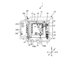
- FIG. It is a schematic front view which shows the appearance of the outdoor unit in the state which mounted the electric component box which concerns on Embodiment 1.
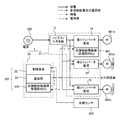
- FIG. It is an electric circuit diagram of the electric component box which concerns on Embodiment 1.
- FIG. It is a simple display figure of the electric component box which concerns on Embodiment 1.
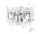
- FIG. It is a simple display figure which shows the form at the time of assembling the electric component box which concerns on Embodiment 1.
- FIG. It is a simple display figure which shows the form at the time of assembling into the outdoor unit in the electric component box which concerns on Embodiment 1.
- FIG. It is a rear view of the electric component box of FIG. It is a simple display figure which shows the form at the time of assembling the electric component box which concerns on Embodiment 2.
- FIG. 16 is a side view showing a state in which the lid portion of the electrical component box of FIG. 16 is closed.
- FIG. 1 is a schematic front view showing the appearance of the outdoor unit in a state where the electrical component box according to the first embodiment is mounted.
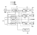
- FIG. 2 is an electric circuit diagram of the electric component box according to the first embodiment. In FIG. 1, the direction of air flow is indicated by a white arrow.
- the configuration of the outdoor unit will be described with reference to FIGS. 1 and 2.
- the outdoor unit 600 includes a housing 600a, a compressor 601, an outdoor heat exchanger 604, a first fan 602, a second fan 603, a pressure sensor 605a, and an electric component box 1. .. Further, the outdoor unit 600 includes a first fan motor 602a for driving the first fan 602 and a second fan motor 603a for driving the second fan 603. As shown in FIG. 2, the electrical component box 1 is connected to various sensors 605.
- the various sensors 605 are a pressure sensor 605a mounted on the outdoor unit 600, a temperature sensor provided on the outdoor unit 600 or an indoor unit (not shown), and the like.
- the housing 600a has, for example, a rectangular parallelepiped shape.
- the housing 600a is composed of a bottom surface portion, a plurality of side panels, a top panel, and the like, and the plurality of side panels and the top panel are removable.
- a suction port is formed on the side panel, and an air outlet is formed on the top panel.
- the arrow X direction in FIG. 1 represents the width direction of the outdoor unit 600
- the arrow Y direction represents the depth direction of the outdoor unit 600
- the arrow Z direction represents the height direction of the outdoor unit 600.
- the compressor 601 sucks in the refrigerant and compresses it into a high temperature and high pressure state.
- the compressor 601 is an inverter compressor having a compressor main body 601b and a compressor motor 601a for driving the compressor main body 601b, and whose capacity can be controlled.
- the rotation speed of the compressor body 601b is controlled by driving the compressor motor 601a by changing the frequency of the inverter according to the speed command of the control device described later.
- the first fan 602 is driven by the first fan motor 602a so that the air volume can be freely adjusted, and blows air to the outdoor heat exchanger 604.
- the second fan 603 is driven by the second fan motor 603a so that the air volume can be freely adjusted, and blows air to the outdoor heat exchanger 604 in the same manner as the first fan 602.
- the first fan 602 and the second fan 603 are each composed of, for example, a propeller fan.
- the outdoor heat exchanger 604 exchanges heat between the refrigerant and air.
- the outdoor heat exchanger 604 is arranged on each of the four front, rear, left, and right sides of the housing 600a of the outdoor unit 600, and the first fan 602 and the second fan 603 are the upper portions of the outdoor unit 600. It is provided in.
- the first fan 602 and the second fan 603 When at least one of the first fan 602 and the second fan 603 is being driven, air is sucked into the housing 600a through the suction port of the side panel, and the housing is sucked through the air outlet of the top panel. Air is blown out of 600a.
- the air exchanges heat with the refrigerant in the outdoor heat exchanger 604 arranged along the side surface of the outdoor unit 600, and goes out of the housing 600a from the air outlet provided on the top panel of the housing 600a. Blow out.
- the outdoor unit 600 is connected to an indoor unit (not shown) equipped with an indoor heat exchanger and a decompression device via a refrigerant pipe, and includes a compressor 601, an outdoor heat exchanger 604, an indoor heat exchanger, and the like.
- a refrigerant circuit is formed by connecting a decompressor and the like via a refrigerant pipe.
- the refrigerant control parts and the electrical and electronic parts are placed below the heat exchanger to avoid the air passage so that the air volume passing through the housing 600a is not obstructed. It is desirable to be placed.
- the refrigerant control component is a component such as a compressor 601, a pressure sensor 605a, and a solenoid valve used for controlling the state of the refrigerant circulating in the refrigerant circuit.
- the electric / electronic component is a component that controls the above-mentioned refrigerant control component, and is a component included in the electrical component box 1 that constitutes the control device. Since the refrigerant control component is connected to the electric component box 1 by wiring, it is desirable that the refrigerant control component is arranged near the electric component box 1.
- the front surface is a service surface on which an operator performs work
- the portion provided below the outdoor heat exchanger 604 in the right half of the front surface of the housing 600a is a service panel 600a1.
- the service panel 600a1 is a removable panel.
- the electric component box 1 is arranged in the space on the right side in the housing 600a of the outdoor unit 600. That is, the electrical component box 1 is located behind the service panel 600a1 in the outdoor unit 600, and when a service such as maintenance or repair of the electrical component box 1 is performed, the operator can remove the service panel 600a1. You can access the electrical box 1.
- the electric component box 1 when the electric component box 1 is incorporated into the outdoor unit 600, the electric component box 1 is incorporated into the housing 600a via the service surface in a state where the service panel 600a1 of the housing 600a is removed. That is, the service panel 600a1 constitutes a part of the front surface of the housing 600a at a position facing the electrical component box 1, and the housing 600a can be opened and closed.
- FIG. 3 is a simplified display diagram of the electrical component box according to the first embodiment.
- the electrical component box 1 is configured by attaching a plurality of electrical components, a plurality of substrates, and the like to an electrical component box main body made of a metal case.
- the electrical component box 1 is a control device for the heat pump device, and controls the operation of the heat pump device by a plurality of electrical and electronic components.
- a plurality of electric parts and the like are arranged in a plurality of layers in the main body of the electric component box, and the electric component box 1 includes a first layer portion 10, a second layer portion 20, a rotation fulcrum 30, and a lid. It is composed of parts 40 and the like.
- the first layer portion 10 and the second layer portion 20 are connected so as to be openable and closable by a rotation fulcrum 30.
- the rotation fulcrum 30 is provided on the left side of the first layer portion 10, and the second layer portion 20 is configured to open to the left with respect to the first layer portion 10. Since the electrical component box 1 is composed of a plurality of layers, it is possible to reduce the size of the electrical component box 1 and improve the degree of freedom in shape.
- the rotation fulcrum 30 is composed of, for example, a hinge.
- the rotation fulcrum 30 is made of weather-resistant stainless steel, plated metal, or the like to prevent rust. Further, the rotation fulcrum 30 is preferably painted when corrosion resistance such as salt damage or a sulfur atmosphere is required. Alternatively, the rotation fulcrum 30 may be made of a ceramic or resin molded product.
- the position where the rotation fulcrum 30 is provided in the electrical component box 1 is not limited to the above-mentioned position.
- the rotation fulcrum 30 may be provided so as to be located inside the main body of the electric component box, or may be provided so as to be located outside the main body of the electric component box.
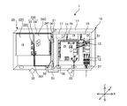
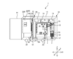
- FIG. 4 is a simplified display diagram showing a mode at the time of assembling the electrical component box according to the first embodiment.
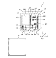
- FIG. 5 is a simplified display diagram showing a mode when the electrical component box according to the first embodiment is incorporated into an outdoor unit.
- FIG. 5 shows an electrical component box with the lid 40 removed. With the first layer portion 10 and the second layer portion 20 of the electrical component box 1 closed, the electrical component box 1 is located on the back side of the outdoor unit 600 so that the first layer portion 10 is located on the back side of the outdoor unit 600. Is incorporated into the outdoor unit 600, and the first layer portion 10 is fixed to the housing 600a of the outdoor unit 600.
- the arrow X direction, the arrow Y direction, and the arrow Z direction are the width direction, the depth direction, and the height direction of the first layer portion 10 in the state where the electric component box 1 is incorporated in the outdoor unit 600, respectively. Represents. Further, in the following description, the width direction of the first layer portion 10 and the width direction of the outdoor unit 600, the depth direction of the first layer portion 10 and the depth direction of the outdoor unit 600, and the height direction of the first layer portion 10 It is assumed that the outdoor unit 600 has the same height direction and width direction as each other.
- the electrical component box 1 includes a power supply terminal block 12, a noise filter board 13, an inverter, a power supply board 24, a control board 22, and the like.
- the inverter includes a plurality of inverter boards such as a first inverter board 14, a second inverter board 15, and a third inverter board 16.
- the solid line arrow indicates the direction in which power is supplied in the strong electric wire
- the broken line arrow indicates the direction in which control power is supplied or the electric signal is transmitted in the weak electric wire
- the one-point chain line arrow indicates communication data in the communication line 53. Indicates the direction in which is transmitted.
- the noise filter substrate 13 is equipped with, for example, a common mode choke coil or the like, and reduces the noise of electricity supplied from the three-phase AC power supply 500.
- the first inverter board 14 mounts a power device or the like that controls the compressor motor 601a, and supplies the compressor motor 601a with a three-phase output having a variable frequency and a variable voltage.
- the second inverter board 15 mounts a power device or the like that controls the first fan motor 602a, and supplies the first fan motor 602a with a three-phase output of a variable frequency and a variable voltage.
- the third inverter board 16 mounts a power device or the like that controls the second fan motor 603a, and supplies the second fan motor 603a with a three-phase output having a variable frequency and a variable voltage.
- the power supply board 24 is equipped with a power supply circuit that converts the three-phase AC power supply 500 into a DC power supply and supplies control power to each part.
- the power supply board 24 is provided with a third connector 241 or the like that is connected to the electrical and electronic components of the first layer portion 10.
- the electrical / electronic component of the first layer portion 10 may be referred to as a first layer electrical component.
- the control board 22 is equipped with a control circuit that controls the operation of each part.
- the control board 22 is provided with a first connector 221 connected to the refrigerant control component, a second connector 222 connected to the first layer electric component, and the like.
- the control board 22 is provided with a communication unit 23 that communicates with external and internal devices, a display unit 224 composed of a liquid crystal display and the like, an operation unit 225 composed of a plurality of switches and the like.
- the power supply terminal block 12 connected to the three-phase AC power supply 500 is connected to the noise filter board 13 by a strong electric wire. Further, the noise filter board 13 is connected to the first inverter board 14, the second inverter board 15, the third inverter board 16, the power supply board 24, and the control board 22 via a plurality of strong electric wires.
- the first inverter board 14 connected to the compressor motor 601a is configured to control a current larger than the current controlled by each of the second inverter board 15 and the third inverter board 16.
- the power supply board 24 is connected to the control board 22, the first inverter board 14, the second inverter board 15, and the third inverter board 16 via a plurality of weak electric wires.
- the control board 22 is connected to various sensors by weak electric wires, and electric signals from various sensors 605 are input to the control board 22 via the weak electric wires.
- the control board 22 is connected to the first inverter board 14, the second inverter board 15, the third inverter board 16 and the power supply board 24 via a plurality of communication lines 53, and outputs a control command to each board. There is.
- the control board 22 has a communication unit 23 for communicating with external and internal devices, and a communication line 53 whose one end is connected to the communication unit 23 is pulled out of the electrical component box 1.
- the above-mentioned strong electric wire and weak electric wire may be simply referred to as an electric wire 51, and the electric wire 51, the communication line 53, and the connection line 54 with the refrigerant control component are not distinguished. Sometimes it is simply wiring.
- the electric component box main body has a substantially rectangular parallelepiped box shape with an open front surface.
- the open front surface of the electrical component box main body is referred to as a first opening surface 31.
- the first opening surface 31 of the electric component box main body is arranged so as to face the service surface of the housing 600a.
- a lid 40 made of sheet metal is detachably attached to the main body of the electrical component box via screws or the like.
- the first opening surface 31 of the electric component box main body is closed by the lid portion 40 to prevent rainwater, dust, etc. from entering the electric component box main body.
- a hinge for connecting the lid 40 and the main body of the electrical component box may be further provided, and the lid 40 may open and close the first opening surface 31 by a rotation fulcrum. In this case, serviceability can be improved.
- the electrical component box main body is divided into two in the depth direction (arrow Y direction), and has a first layer main body 11 on the back side and a second layer main body 21 on the front side. That is, when the electrical component box main body is viewed from the front, the sizes of the first layer main body 11 and the second layer main body 21 are substantially the same.
- the first layer main body 11 is composed of sheet metal arranged on four side surfaces, top, bottom, left and right, and a back surface, and has a box shape with an open front surface.
- the opening on the front surface of the second layer main body 21 is the first opening surface 31 in the electric component box main body.
- the second layer main body 21 is made of sheet metal arranged on four side surfaces of upper, lower, left and right, and has a frame shape in which the front surface and the back surface are open.
- the open back surface of the second layer main body 21 is referred to as a second opening surface 32
- the open front surface of the first layer main body 11 is referred to as a third opening surface 33.
- a part of a plurality of electrical and electronic parts (first layer electric parts) included in the electric component box is attached to the first layer main body 11 to form the first layer portion 10 described above, and the second layer main body 21
- the remaining components of the plurality of electrical and electronic components are attached to the second layer portion 20.
- FIG. 5 in a state where the first layer portion 10 and the second layer portion 20 are closed, the edge portion of the second opening surface 32 in the second layer main body 21 and the third opening surface in the first layer main body 11 The edges of 33 face each other.
- the electric component box 1 is provided with a water stop member 57 for stopping water at each opening formed in the main body of the electric component box.
- the water blocking member 57 is made of, for example, a foam sealing material such as an Ept sealer or a rubber material.
- the water blocking member 57 includes an edge of the third opening surface 33 in the first layer main body 11 as shown in FIG. 3 and an edge of the first opening surface 31 in the second layer main body 21 as shown in FIG. It is attached to the part.
- the water stop member 57 suppresses the intrusion of rainwater or the like from each opening surface between the first layer main body 11 and the second layer main body 21 and between the second layer main body 21 and the lid portion 40.
- Flange is formed on the edge of the third opening surface 33 in the first layer main body 11 and the edge of the first opening surface 31 in the second layer main body 21 as a sticking allowance to which the water blocking member 57 is stuck. ing.
- the flange may be formed by bending the sheet metal constituting the first layer main body 11 and the second layer main body 21, respectively, or may be formed of another sheet metal.
- the water blocking member 57 may be attached to the edge of the second opening surface 32 of the second layer main body 21 and the back edge of the lid 40. In this case as well, the same effect as in the above case can be obtained.
- the sheet metal forming the first layer main body 11 and the sheet metal forming the second layer main body 21 are each formed with wiring holes through which one or a plurality of wirings are passed, and rubber bushes 56 are provided in the wiring holes. There is.
- the position of providing the wiring hole in the first layer main body 11 and the second layer main body 21 is selected according to the position of the electrical and electronic component to which the wiring is connected.
- the wiring holes are formed in the sheet metal forming the lower surface of the first layer main body 11 and the sheet metal forming the lower surface of the second layer main body 21, respectively.
- the wiring holes may be formed on the side surfaces of the first layer main body 11 and the second layer main body 21 where the rotation fulcrum 30 is provided.
- the first layer portion 10 contains a heavy object and a heat generating component that requires active cooling among a plurality of electrical and electronic components.
- the heat generating components that require active cooling are power devices and the like mounted on the first inverter board 14, the second inverter board 15, and the third inverter board 16, respectively.
- the first inverter board 14 includes heat-generating components such as a rectifier circuit, an IGBT module, a boost converter, a step-down converter, a three-terminal regulator for power supply, a main circuit capacitor, and a reactor.
- Each of the second inverter board 15 and the third inverter board 16 also includes heat-generating components similar to those of the first inverter board 14.
- the first layer portion 10 includes a power supply terminal block 12 and a noise filter substrate 13 among a plurality of electrical and electronic components.
- the electrical component box 1 is configured so that the weight of the first layer portion 10 is heavier than the weight of the second layer portion 20.
- the gravity of the inverter may be heavier than that of the second layer portion 20.
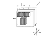
- FIG. 6 is a rear view of the electrical component box of FIG.
- the first layer portion 10 includes a cooling member 300 such as a heat sink.
- the first inverter board 14, the second inverter board 15, and the third inverter board 16 are attached to the first layer main body 11 so that the thermal resistance between the heat radiating surface of each of the heat generating components and the cooling member 300 described above becomes small.
- the back surfaces of the first inverter board 14, the second inverter board 15, and the third inverter board 16 are arranged so as to come into contact with the inner surface of the sheet metal constituting the back surface of the first layer portion 10 main body.
- the cooling member 300 is arranged on the outer surface of the sheet metal forming the back surface of the first layer main body 11.
- the heat generating component may be cooled by the top flow wind generated by the first fan 602 and the second fan 603, or the plurality of inverter boards may be air-cooled.
- a shaft flow fan may be provided separately.
- the cooling member 300 is not limited to the heat sink.
- a refrigerant cooler is provided so as to come into contact with the heat radiating surface of the heat generating component, and the heat generating component is cooled by flowing a part or the entire flow rate of the refrigerant flowing in the housing 600a of the outdoor unit 600 to the refrigerant cooler. It may be.
- an electronic expansion valve is provided in the pipe provided with the refrigerant cooler branched from the main circuit to control the flow rate of the refrigerant flowing to the refrigerant cooler. As a result, the amount of cooling can be adjusted.
- the electronic expansion valve is one of the above-mentioned refrigerant control components, and is preferably arranged below the outdoor heat exchanger 604 in the outdoor unit 600.
- the cooling amount is improved by using a heat pipe that uses water to transfer the heat to the position where the wind blows. Can be made to. Further, in order to reduce the thermal resistance between the cooling member 300 and the heat-generating component, heat-dissipating grease or sheet using a carbon-based material, silicon, or acrylic is interposed between the cooling member 300 and the heat-generating component. May be good.
- the electrical component box 1 is equipped with a DC reactor 17 to improve the power factor. Since the DC reactor 17 is a heavy object and a heat generating component, it is included in the first layer portion 10. Specifically, the first layer main body 11 is provided with the sheet metal constituting the first layer main body 11. It is attached by a fastening member such as a screw so as to make thermal contact with the cooling member 300 via the cooling member 300.
- the first inverter board 14 is placed on the first fan 602 and the second fan 602. It is better to place it at the position farthest from the fan 603. This is because the controlled current of the first inverter board 14 for driving the compressor motor 601a is larger than the current controlled by the second inverter board 15 and the third inverter board, and the amount of heat generated is also large.
- the electric component box 1 is incorporated in the outdoor unit 600 from the second inverter board 15 and the third inverter board 16.
- the first inverter board 14 is arranged below. With such a configuration, the cooling member 300 that cools the first inverter board 14 can be cooled by a lower temperature wind, the cooling member 300 can be downsized, and the quality of the first inverter board 14 can be improved.
- the second layer portion 20 basically does not include a heat generating component, but includes a control board 22 and a power supply board 24.
- the electronic substrate attached to the second layer main body 21 may be referred to as a “second layer substrate portion”.
- the control board 22 and the power supply board 24 are the second layer board portions 220. That is, the second layer substrate portion 220 has a function of controlling the operation of the refrigerant control component and supplying a control power supply to the first layer electric component.
- the second layer substrate portion 220 moves together with the second layer main body 21 when the second layer portion 20 is opened and closed.
- the second layer portion 20 includes an auxiliary support column 201 that assists in fixing the control board 22, the power supply board 24, wiring, and the like to the second layer main body 21.
- the auxiliary support column 201 can be freely fixed at a fixed position according to the size of each of the control board 22 and the power supply board 24 attached to the second layer main body 21.
- the auxiliary support column 201 is, for example, a member extending in the vertical direction provided at a substantially central position in the width direction of the electrical component box 1, and has a second layer via an upper end portion and a lower end portion so that the left and right positions can be changed. It is attached to the inner surface of the main body 21.
- control board 22 and the power supply board 24 are arranged side by side.
- the control board 22 is arranged in the right half of the space inside the second layer main body 21, and the power supply board 24 is arranged in the left half closer to the rotation fulcrum 30 than the control board 22.
- the control board 22 has a second layer so that the right side surface and the upper surface of the outer circumference of the control board 22 contact the inner surface of the second layer main body 21, and the left side surface of the outer circumference of the control board 22 contacts the right side surface of the auxiliary column 201. It is fixed to the main body 21.
- the second layer of the power supply board 24 is such that the left side surface and the upper surface of the outer circumference of the power supply board 24 are in contact with the inner surface of the second layer main body 21, and the right side surface of the outer circumference of the power supply board 24 is in contact with the left side surface of the auxiliary support column 201. It is fixed to the main body 21.
- the surface provided with the third connector 241 or the like connected to the first layer electric component is referred to as C surface 24C
- S surface 24S the back surface of C surface 24C
- the C surface 24C of the power supply board 24 is located on the second opening surface 32 side which is the back surface of the second layer main body 21, and is the S surface of the power supply board 24.
- the 24S is located on the first opening surface 31 side, which is the front surface of the second layer main body 21.
- the surface on which the display unit 224 is provided is referred to as C surface 22C
- the back surface of C surface 22C is referred to as S surface 22S.
- the C surface 22C of the control board 22 is located on the first opening surface 31 side which is the front surface of the second layer main body 21, and is the S surface of the control board 22.
- 22S is located on the second opening surface 32 side, which is the back surface of the second layer main body 21.
- each of the C surface 22C and the S surface 22S of the control board 22 is a surface on which a connector can be provided.
- the electronic components of the control board 22 are soldered by reflow / reflow, and there is no difference in the components that can be mounted on the C surface 22C and the S surface 22S. Parts that do not support reflow / reflow are installed after the reflow / reflow process by a spot welder or the like. Further, the display unit 224, the operation unit 225, the communication unit 23, and the like are provided on the C surface 22C of the control board 22. In the control board 22, all the first connectors 221 to which the connecting line 54 with the refrigerant control component is connected are provided on the C surface 22C, and the second connector 222 connected to the first layer electric component is on the S surface 22S. It is provided.
- the electric component box in the manufacturing stage of the electric component box 1, the electric component box is in a state where the first layer main body 11 and the second layer main body 21 are opened to the left and right by the rotation fulcrum 30. 1 is placed on the production line. Therefore, at the manufacturing stage of the electrical component box 1, the work of attaching electrical and electronic components to the first layer main body 11 and the second layer main body 21, or the work of attaching the wiring straddling the first layer main body 11 and the second layer main body 21 However, it can be easily done while checking the connection destination.
- the wiring extending from the first layer main body 11 to the second layer main body 21 is connected after being once taken out of the electric component box 1 through the wiring hole formed in the lower part of the electric component box 1.
- the rubber bush 56 provided in the wiring hole through which the wiring is passed further narrows the range of motion of the wiring, and it is possible to prevent water from entering the main body of the electrical component box and contact with the edge of the sheet metal.
- the rubber bush 56 is provided at a position close to the rotation fulcrum 30, the range of motion of the wiring is further narrowed, and the effects of avoiding the intrusion of water and avoiding contact with the sheet metal are enhanced.
- the power supply board 24 included in the second layer portion 20 and supplying power to the first layer portion 10 is also arranged at a position close to the rotation fulcrum 30 in which the rubber bush 56 is arranged. Since the output from the power supply board 24 is a weak electric power, it is preferable to arrange the output from the strong electric system boards such as the first inverter board 14, the second inverter board 15, and the third inverter board 16 from the viewpoint of noise propagation. Further, it is preferable that the strong electric wire is also arranged at a position away from the rotation fulcrum 30 in the main body of the electric component box.
- the electrical component box 1 When the electrical component box 1 is incorporated into the outdoor unit 600, the electrical component box 1 is arranged in the housing 600a from the service side with the second layer portion 20 closed as shown in FIG.
- the connection line 54 from the refrigerant control component is connected to the first connector 221 of the control board 22 of the second layer portion 20 after the electrical component box 1 is installed in the housing 600a by the operator. Since the first connector 221 is provided on the C surface 22C of the control board 22 arranged so as to face the first opening surface 31, the operator can use the second layer portion 20 with respect to the first layer portion 10. It can be assembled to the outdoor unit 600 without opening.
- the electric component box 1 has the first opening surface 31, and includes the electric component box main body composed of the first layer main body 11 and the second layer main body 21. Further, the electrical component box 1 is a component that controls the refrigerant control component and is attached to the second layer main body 21 and is attached to the second layer substrate portion 220, and is a component that controls the refrigerant control component and is attached to the first layer main body 11. Includes attached first layer electrical components. Further, the electrical component box 1 includes a rotation fulcrum 30 for connecting the first layer main body 11 and the second layer main body 21, and the second layer main body 21 can be opened and closed with respect to the first layer main body 11 by the rotation fulcrum 30. Is.
- the second layer substrate portion 220 has a first surface on the first opening surface 31 side and a second surface which is the back surface of the first surface, and the first surface is connected to the refrigerant control component.
- a connector 221 is provided, and a second connector 222 connected to a first-layer electric component is provided on the second surface.
- the second layer portion 20 can be opened and the first layer portion 10 and the second layer portion 20 can be seen at once, and the wiring connection between the two can be made. Further, at the stage of assembling to the outdoor unit, the connection line 54 with the refrigerant control component can be connected to the first connector 221 provided on the front surface of the second layer portion 20 without opening the second layer portion 20. , The work becomes easy. Therefore, in the electrical component box 1 having a hierarchical structure, both serviceability and assembling property can be achieved at the same time.
- the heat pump device (outdoor unit 600) includes the above-mentioned electric component box 1, a pressure sensor 605a provided in the refrigerant circuit, an electromagnetic valve, and at least one of an electronic expansion valve. ..
- the refrigerant control component to which the first connector 221 is connected is a pressure sensor 605a, a solenoid valve or an electronic expansion valve. Therefore, even in the heat pump device, both serviceability and assembling property can be achieved at the same time.
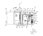
- FIG. 7 is a simplified display diagram showing a mode at the time of assembling the electrical component box according to the second embodiment.
- FIG. 8 is a simplified display diagram showing a mode when the electrical component box according to the second embodiment is incorporated into the outdoor unit.
- the configuration of the electrical component box according to the second embodiment which is different from that of the first embodiment, will be described.
- the second layer substrate portion mounted on the second layer portion 20 that can be opened and closed with respect to the first layer portion 10. Since the connectors are provided on both the front surface and the back surface of the 220, the same effect as in the case of the first embodiment can be obtained.
- the second layer substrate portion 220 is composed of the individually formed control substrate 22 and the power supply substrate 24 has been described.
- the functions of the power supply board 24 are integrated in the control board 22 of the first embodiment.
- the second layer board portion 220 mounted on the second layer section 20 is configured by mounting a control circuit and a power supply circuit on one board.
- the C surface 220C of the second layer substrate portion 220 is located on the first opening surface 31 side which is the front surface of the second layer main body 21, and the S surface 220S of the second layer substrate portion 220 is the back surface of the second layer main body 21. It is located on the side of the second opening surface 32.
- the surface of the second layer substrate unit 220 on which the display unit 224, the operation unit 225, and the like are provided is referred to as a C surface 220C
- the back surface of the C surface 220C is referred to as an S surface 220S.
- Both the S surface 220S and the C surface 220C of the second layer substrate portion 220 are surfaces on which a connector can be provided, and the C surface 220C and the S surface 220S are the same as in the case of the control board 22 of the first embodiment. There is no difference in the parts that can be mounted.
- the control circuit all the first connectors 221 connected to the refrigerant control component via the connecting line 54 are provided on the C surface 220C of the second layer substrate portion 220.
- the third connector 241 connected to the electric / electronic component of the first layer portion 10, that is, the first layer electric component in the power supply circuit is provided on the S surface 220S of the second layer substrate portion 220.
- the area in which the electrical and electronic components are arranged in the second layer portion 20 can be reduced as compared with the case where the control board 22 and the power supply board 24 are arranged side by side. Therefore, the number of substrates can be reduced as compared with the conventional case, and the cost can be reduced.
- the second layer portion 20 by reducing the area in which the electrical and electronic components are arranged in the second layer portion 20, it is possible to provide a space in the second layer main body 21 in which the substrate or the like is not arranged. As a result, even when the second layer portion 20 is closed as shown in FIG. 8, the inside of the first layer main body 11 can be visually recognized through the space.
- an opening in which electrical and electronic components are not arranged is provided in a region that overlaps with the power supply terminal block 12 and the noise filter substrate 13 of the first layer portion 10 in a front view. In the example shown in FIG. 8, the left side surface and the upper surface of the outer periphery of the second layer substrate portion 220 come into contact with the inner surface of the second layer main body 21.
- the second layer substrate portion 220 is fixed to the second layer main body 21 so as to be arranged on the rotation fulcrum 30 side, that is, on the left side in the second layer main body 21.
- the power supply terminal block 12 and the noise filter substrate 13 are arranged on the right side so as to be separated from the rotation fulcrum 30. That is, in the front view of the electrical component box body, the second layer substrate portion 220 is arranged on the rotation fulcrum 30 side, and the power supply terminal block 12 is arranged at a position farther from the rotation fulcrum 30 than the second layer substrate portion 220. Has been done. Therefore, even when the second layer portion 20 is closed, the operator can use the power terminal block 12 and the noise filter of the first layer portion 10 from the first opening surface 31 through the opening in the second layer portion 20. The substrate 13 and the like can be visually observed.
- the second layer main body 21 is provided with a region, that is, an opening in which the parts are not attached when the first opening surface 31 is viewed from the front.
- the operator can see the power terminal block 12 and the like of the first layer portion 10 through the first opening surface 31 on the front surface and the opening in the second layer main body 21, so that the outdoor unit 600 can be viewed.
- the wiring connection can be easily performed without opening the second layer portion 20.
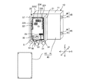
- FIG. 9 is a simplified display diagram showing a mode at the time of assembling the electrical component box according to the third embodiment.
- FIG. 10 is a simplified display diagram showing a mode when the electric component box according to the third embodiment is incorporated into an outdoor unit.
- the configuration of the electrical component box according to the third embodiment which is different from that of the second embodiment, will be described.
- the second layer substrate portion mounted on the second layer portion 20 that can be opened and closed with respect to the first layer portion 10. Since the connectors are provided on both the front surface and the back surface of the 220, the same effect as in the case of the first embodiment can be obtained.
- the first layer main body 11 and the second layer main body 21 have a shape in which a substantially rectangular parallelepiped box-shaped electrical component box main body is divided into two in the front-rear direction (arrow Y direction). As shown in FIG. 8, the sizes of the first layer main body 11 and the second layer main body 21 were substantially the same in the front view.
- the size of the second layer main body 21 in the second embodiment is larger than that of the first layer main body 11 according to the substrate size of the second layer substrate portion 220. It is configured small.
- the distance between the sheet metals forming the left side surface and the right side surface of the second layer main body 21 matches the width of the second layer substrate portion 220 in the lateral direction (arrow X direction).
- the lid portion 40 is made of a sheet metal having a square shape, and is attached to the front surface of the second layer main body 21 so as to cover the first opening surface 31 of the second layer main body 21.
- the lid portion 40 is a front view of the electrical component box 1 in a state where the second layer main body 21 is closed, and the front surface of the portion of the first layer main body 11 that protrudes to the outside of the second layer main body 21 is viewed. It has a first lid portion 41 for covering, a second lid portion 42 for covering the front surface of the second layer main body 21, and a lid connecting portion 43.
- the lid connecting portion 43 connects the first lid portion 41 and the second lid portion 42.
- the lid portion 40 has a substantially S-shape in a plan view, and may be formed by bending one sheet metal in two places, for example, as shown in FIG.
- the operator by removing the lid portion 40 from the main body of the electric component box, the operator protrudes inside the second layer main body 21 and outside the second layer main body 21 in the first layer main body 11.
- the electrical and electronic parts of the part can be seen from the front. Therefore, the operator can easily check the state of the electrical and electronic components inside the first layer main body 11 without opening the second layer main body 21 by the rotation fulcrum 30.
- FIG. 10 with the lid portion 40 removed, when the electrical component box 1 is viewed from the front, the C surface 220C of the second layer substrate portion 220 arranged in the second layer main body 21 and the first
- the power supply terminal block 12 and the noise filter substrate 13 arranged on the right side in the layer body 11 can be visually recognized.
- the second layer main body 21 is formed smaller than the first layer main body 11 according to the size of the second layer substrate portion 200.
- the operator can see the electrical and electronic parts such as the power supply terminal block 12 arranged outside the second layer main body 21 in the first layer main body 11, and thus the embodiment is also carried out in the third embodiment.
- the same effect as in the case of Form 2 can be obtained.
- the lid portion 40 may be configured by bending one sheet metal as described above, or may be configured by two sheet metals of the first lid portion 41 and the second lid portion 42 without providing the lid connecting portion 43. You may.
- the lid portion 40 is composed of two sheets of metal, the first lid portion 41 and the second lid portion 42, the number of sheets increases, but the operator can use the two sheets that form the lid portion 40 when the electrical component box 1 is installed. All you have to do is remove the sheet metal, and you can work without opening the second layer 20.
- a configuration example in which the lid portion 40 does not include the lid connecting portion 43 and the first lid portion 41 and the second lid portion 42 are individually configured will be described.
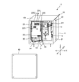
- FIG. 11 is a simplified display diagram showing a form at the time of assembly in the first modification of the electrical component box according to the third embodiment.
- FIG. 12 is a simplified display diagram showing a mode when the electrical component box according to the third embodiment is incorporated into the outdoor unit in the first modification.
- the first lid portion 41 is composed of a part of the sheet metal constituting the second layer main body 21. Specifically, the first lid portion 41 is on the right side from the back end side of the sheet metal constituting the right side surface of the second layer main body 21 in a state where the second layer portion 20 is closed as shown in FIG. It is composed of sheet metal extending to.
- FIG. 13 is a simplified display diagram showing a form at the time of assembly in the second modification of the electrical component box according to the third embodiment.
- FIG. 14 is a simplified display diagram showing a mode when the electric component box according to the third embodiment is incorporated into the outdoor unit in the second modification.
- the lid portion 40 of the second modification is provided with a fixing portion 45 for fixing the first lid portion 41 and the first layer main body 11 to the lid portion 40 of the first modification.
- the fixing portion 45 is provided at a portion where the first layer main body 11 and the first lid portion 41 extending from the second layer main body 21 come into contact with each other in a state where the second layer portion 20 is closed by the rotation fulcrum 30. ..
- the fixing portion 45 includes a first fixing portion 46 provided on the edge of the third opening surface 33 of a portion of the first layer main body 11 that protrudes to the outside of the second layer main body 21, and a first lid. It has a second fixing portion 47 provided at a position facing the first fixing portion 46 on the outer peripheral portion of the portion 41.
- the first fixing portion 46 is provided on the right edge portion of the third opening surface 33 in the second layer main body 21, and the second fixing portion 47 is the right edge portion on the outer peripheral portion of the first lid portion 41. It is provided in the part.
- the first fixing portion 46 and the second fixing portion 47 each have screw holes, and the degree of adhesion between the first layer main body 11 and the second layer main body 21 is increased by screw tightening.
- the screw hole of the second fixing portion 47 is formed to be larger than the outer diameter of the screw to be passed through the screw hole so that the fixing and the release can be easily performed.
- the second layer main body 21 has a first lid portion 41 that closes a part of the front surface of the first layer main body 11, and the first lid portion 41 is , A part of the sheet metal of the second layer main body 21 is extended.
- the electric component box main body includes a fixing portion 45.
- the fixing portion 45 is provided in the first layer main body 11 and has a screw hole formed in the first fixing portion 46, and is provided in the second layer main body 21 and has a screw hole larger than the screw hole of the first fixing portion 46.
- FIG. 15 is a simplified display diagram showing a mode at the time of assembling the electrical component box according to the fourth embodiment.
- FIG. 16 is a simplified display diagram showing a mode when the electrical component box according to the fourth embodiment is incorporated into an outdoor unit.
- FIG. 17 is a side view showing a state in which the lid 40 of the electrical component box of FIG. 16 is closed.
- the configuration of the electrical component box 1 in the fourth embodiment different from that of the second embodiment will be described.
- the second layer substrate portion mounted on the second layer portion 20 that can be opened and closed with respect to the first layer portion 10. Since the connectors are provided on both the front surface and the back surface of the 220, the same effect as in the case of the first embodiment can be obtained.
- the first layer main body 11 and the second layer main body 21 have a shape in which a substantially rectangular parallelepiped box-shaped electrical component box main body is divided into two in the front-rear direction (arrow Y direction).
- the sheet metal forming the upper surface of the first layer main body 11 and the sheet metal forming the upper surface of the second layer main body 21 were respectively provided horizontally.
- the electric component box is installed on the upper part of the first layer portion 10 in a state where the second layer portion 20 is closed by the rotation fulcrum 30, and extends forward so as to cover the upper surface of the second layer main body 21. It has a roof portion 101.
- the upper surface of the second layer main body 21 is installed on the sheet metal forming the upper surface of the second layer main body 21 and the first layer main body 11 when the second layer main body 21 is closed by the rotation fulcrum 30.
- the structure is lowered toward the front.
- the upper surface of the first layer main body 11 and the roof portion 101 installed on the upper surface of the first layer main body 11 are configured to be gradually lowered toward the rear.
- the roof portion 101 is the sheet metal forming the upper surface of the first layer main body 11. May be configured by extending forward.
- the first layer portion 10 includes a roof portion 101 that covers both the upper surface of the first layer main body 11 and the upper surface of the second layer main body 21.
- FIG. 18 is a simplified display diagram showing a mode at the time of assembling the electrical component box according to the fifth embodiment.
- FIG. 19 is an exploded perspective view showing the configuration of the second layer main body of the electrical component box of FIG.
- FIG. 20 is a simplified display diagram showing a mode when the electrical component box according to the fifth embodiment is incorporated into an outdoor unit.
- the configuration of the electrical component box in the fifth embodiment which is different from that of the second embodiment, will be described.
- the second layer substrate portion mounted on the second layer portion 20 that can be opened and closed with respect to the first layer portion 10. Since the connectors are provided on both the front surface and the back surface of the 220, the same effect as in the case of the first embodiment can be obtained.
- the first layer main body 11 and the second layer main body 21 have a shape in which a substantially rectangular parallelepiped box-shaped electrical component box main body is divided into two in the front-rear direction (arrow Y direction).
- the second layer main body 21 had a frame shape in which sheet metal was arranged on four side surfaces on the upper, lower, left, and right sides, and the front and back surfaces were open.
- the second layer main body 21 constitutes the front portion of the side surface of the box-shaped electric product box main body where the rotation fulcrum 30 is provided, and the first layer main body 11 is the electric product. It constitutes the rest of the box body.
- a rotation fulcrum 30 is provided on the left side surface of the electric component box main body
- the second layer main body 21 constitutes a front portion of the left side surface of the electric component box main body. ..
- the second layer substrate portion 220 is attached to the second layer main body 21 by the substrate, but in the fifth embodiment, the second layer main body 21 is provided with the attachment portion 210, and the second layer main body portion 21 is provided.
- the two-layer board portion 220 is attached to the second layer main body 21 via the attachment portion 210.
- the mounting portion 210 is fixed to the second layer main body 21 so that the left side surface of the mounting portion 210 contacts the inner surface of the second layer main body 21.
- the mounting portion 210 has a frame shape in which a window portion 215 opened in the center of the plate-shaped member is formed. With the second layer substrate portion 220 attached to the mounting portion 210, the second layer substrate portion 220 comes into contact with the edge portion of the window portion 215 or the inner peripheral surface of the window portion 215 on one surface of the mounting portion 210. There is.
- the operator opens and closes the second layer portion 20 by the rotation fulcrum 30 and is attached to the mounting portion 210. Both sides of the layer substrate portion 220 can be seen.
- the first wiring hole 102a through which the wiring connected to the first layer portion 10 is passed is formed at a position on the inner side of the sheet metal forming the lower surface of the first layer main body 11.
- a second wiring hole 102b through which the wiring connected to the second layer portion 20 is passed is formed at a position on the front side of the sheet metal forming the lower surface of the first layer main body 11.
- the second wiring hole 102b in the first layer main body 11 is provided closer to the rotation fulcrum 30 than the first wiring hole 102a. Further, in order to reduce the contact between the wiring and the electrical and electronic components caused by opening and closing the second layer main body 21, rubber bushes 56 are provided in the first wiring hole 102a and the second wiring hole 102b.
- the opening surface of the electric component box main body can be reduced, and the upper surface of the second layer portion 20 is the upper surface of the first layer main body 11 in a state where the second layer portion 20 is closed. Since it is covered, it is possible to suppress the intrusion of rainwater and the like as in the case of the fourth embodiment.
- the mounting portion 210 is provided at a position close to the rotation fulcrum 30, and the second layer substrate portion 220 is mounted on the mounting portion 210. It is not necessary to provide 201. However, in order to prevent the end portion of the second layer substrate portion 220 opposite to the rotation fulcrum 30 from becoming unstable due to the transportation vibration of a truck or the like, the auxiliary support column 201 is provided in the first layer main body 11. , The end portion of the second layer substrate portion 220 may be fixed by the auxiliary support column 201.
- FIG. 21 is a simplified display diagram showing a mode at the time of assembly in the electrical component box according to the sixth embodiment.
- FIG. 22 is an exploded perspective view showing the configuration of the second layer main body of the electrical component box of FIG. 21.
- FIG. 23 is a simplified display diagram showing a mode when the electrical component box according to the sixth embodiment is incorporated into an outdoor unit. With reference to FIGS. 21 to 23, a configuration different from that of the second embodiment will be described for the electrical component box 1 of the sixth embodiment.
- the configuration of the second layer substrate portion 220, the shapes of the first layer main body 11 and the second layer main body 21 constituting the electric component box main body, and the point that the electric component box includes the mounting portion 210. Different from the case of the second embodiment.
- the second layer board portion 220 mounted on the second layer section 20 has a configuration in which a control circuit and a power supply circuit are mounted on one board.
- the second layer board portion 220 is composed of a control board 22 on which a control circuit is mounted and a power supply board 24 on which a power supply circuit is mounted, and each of the control board 22 and the power supply board 24 is electronic. It has mounting surfaces 22a and 24a for components and non-mounting surfaces 22b and 24b.
- the display unit 224, the operation unit 225, and the first connector 221 to which the connection line 54 from the refrigerant control component is connected are provided on the mounting surface 22a of the control board 22.
- the mounting surface 24a of the power supply board 24 is provided with an electrical / electronic component of the first layer portion 10, that is, a third connector 241 connected to the first layer electrical component.
- the second layer main body 21 constitutes the front portion of the side surface of the box-shaped electric component box main body on which the rotation fulcrum 30 is provided, and the first layer main body 11 is the electric component. It constitutes the rest of the box body.
- the rotation fulcrum 30 is provided on the left side surface of the electric component box main body, and the second layer main body 21 constitutes the front portion of the left side surface of the electric component box main body. ..
- the second layer main body 21 is provided with a mounting portion 210, and the second layer substrate portion 220 is attached to the second layer main body 21 via the mounting portion 210.
- the mounting portion 210 is fixed to the second layer main body 21 so that the left side surface of the mounting portion 210 contacts the inner surface of the second layer main body 21.
- the mounting portion 210 is composed of a plate-shaped member provided with a notch portion 211 in a part of the outer circumference, and the second layer portion 20 is closed as shown in FIG. 23. In the state, it has a first surface 210a which is a front surface and a second surface 210b which is a back surface.
- the control board 22 is attached to the first surface 210a of the mounting portion 210 so that the non-mounting surface 22b of the control board 22 is in contact with the first surface 210a, and the non-mounting surface 24b of the power supply board 24 is attached to the second surface 210b of the mounting portion 210.
- the power supply board 24 is attached so as to be in contact with each other. That is, the second layer board portion 220 of the sixth embodiment is configured such that the control board 22 and the power supply board 24 are arranged back to back via the mounting portion 210.
- the wiring connecting the control board 22 and the power supply board 24 is passed through the notch 211.
- the operator can open and close the second layer portion 20 to open and close the mounting surface 22a of the control board 22 and the mounting surface 24a of the power supply board 24. And can be seen.
- the first wiring hole 102a through which the wiring connected to the first layer portion 10 is passed is formed at a position on the inner side of the sheet metal forming the lower surface of the first layer main body 11.
- a second wiring hole 102b through which the wiring connected to the second layer portion 20 is passed is formed at a position on the front side of the sheet metal forming the lower surface of the first layer main body 11.
- the second wiring hole 102b in the first layer main body 11 is provided closer to the rotation fulcrum 30 than the first wiring hole 102a. Further, in order to reduce the contact between the wiring and the electric / electronic component caused by the opening / closing of the second layer portion 20, it is preferable that the second wiring hole 102b is provided with the rubber bush 56.
- control board 22 and the power supply board 24 are mounted on the mounting portion 210 so as to be back to back, but the first connector and the second connector are provided on the front and back surfaces. Corresponds to the two-layer substrate portion 220. Therefore, even in the sixth embodiment, the same effect as in the case of the first embodiment can be obtained.
- control board 22 and the power supply board 24 constituting the second layer board portion 220 each have non-mounting surfaces 22b and 24b, the control board 22 and the power supply board 24 mounted in the flow process can be mounted. It can be used and the substrate can be easily machined.
- a non-contact power feeding mechanism 400 may be used instead of the power supply board 24.
- the non-contact power supply mechanism 400 has a power transmission unit 400a and a power reception unit 400b, and power is supplied from the power transmission unit 400a to the power reception unit 400b in a non-contact manner.
- the non-contact power feeding mechanism 400 can be configured to feed power from the power transmitting unit 400a made of a coil to the power receiving unit 400b made of an electromagnetic induction coil in a non-contact manner, for example. Further, the non-contact power feeding mechanism 400 has a function of carrying communication data and supplying power.
- a magnetic field resonance method or an electric field coupling method may be adopted for the power supply from the power transmission unit 400a to the power reception unit 400b.
- the configuration may be such that wireless communication is possible in the main body of the electrical component box, for example, separately from the non-contact power feeding mechanism 400.
- a communication means for performing wireless communication may be provided, and communication data may be transmitted / received by the communication means.
- FIG. 24 is an electric circuit diagram of the first modification of the electric component box according to the sixth embodiment.
- the power receiving portion 400b of the non-contact power feeding mechanism 400 is mounted on the first layer portion 10
- the power transmitting portion 400a of the non-contact power feeding mechanism 400 is mounted on the second layer portion 20.
- the power receiving unit 400b is provided on the first inverter board 14, and the power transmitting unit 400a is provided on the second surface 210b of the mounting unit 210.
- the place where the power receiving unit 400b and the power transmitting unit 400a are provided may be anywhere, and the power receiving unit 400b and the power transmitting unit 400a may be arranged so as to face each other in a state where the second layer unit 20 is closed.
- the control power is supplied to the electric / electronic component of the first layer portion by the non-contact power feeding mechanism 400, the electric / electronic component of the first layer portion 10 is supplied with the control power. There is no need to provide a weak wire to supply control power or transmit electrical signals. Further, since the non-contact power feeding mechanism 400 has a function of carrying communication data and supplying power, it is necessary to provide a communication line 53 for transmitting a control signal from the control board 22 on the electrical and electronic components of the first layer portion 10. Nor. Therefore, when the non-contact power feeding mechanism 400 is provided instead of the power supply board 24, the wiring straddling the first layer portion 10 and the second layer portion 20 can be reduced, and the configuration can be simplified.
- FIG. 25 is an electric circuit diagram of a second modification of the electric component box according to the sixth embodiment.
- the power transmission unit 400a of the non-contact power supply mechanism 400 is mounted on the first layer portion 10 provided with the power terminal block 12, and the power reception unit 400b of the non-contact power supply mechanism 400 is mounted on the second layer portion 20. It is installed.
- the first inverter board 14 connected to the compressor motor 601a, the second inverter board 15 connected to the first fan motor 602a, and the third inverter board 16 connected to the second fan motor 603a. Are all provided in the first layer portion 10. Therefore, in the second modification, it is not necessary to connect a strong electric wire from the noise filter substrate 13 provided in the first layer portion 10 to the second layer portion 20, and the wiring straddling the first layer portion 10 and the second layer portion 20. Can be reduced.
- FIG. 26 is an electric circuit diagram of a third modification of the electrical component box according to the sixth embodiment.
- the down transformer 70 is provided in the wiring that connects the noise filter board 13 and the control board 22 and supplies electric power for the control power supply.
- the control power supply can be set to a specified value or less by the configuration of the second modification or the third modification described above.
- FIG. 27 is a simplified display diagram showing a mode at the time of assembling the electrical component box according to the seventh embodiment.
- FIG. 28 is a simplified display diagram showing a mode when the electrical component box according to the seventh embodiment is incorporated into an outdoor unit.
- the configuration of the first layer main body 11 and the arrangement of the electrical and electronic components in the main body of the electric component box are different from those of the first embodiment.
- the configuration of the electrical component box 1 in the seventh embodiment different from that of the first embodiment will be described.
- the electrical component box 1 of the seventh embodiment is composed of a first layer portion 10, a second layer portion 20, a rotation fulcrum 30, and the like.
- the electrical component box 1 of the seventh embodiment does not include the lid portion 40 of the first embodiment, and the electrical component box main body has a substantially rectangular parallelepiped box shape.
- the electrical component box main body is composed of a first layer main body 11 and a second layer main body 21 that are substantially symmetrical in the front-rear direction in the depth direction (arrow Y direction). That is, the first layer main body 11 is composed of sheet metal arranged on the upper, lower, left and right four side surfaces and the back surface, and the second layer main body 21 is composed of sheet metal arranged on the upper, lower, left and right four side surfaces and the front surface. There is.
- the open back surface of the second layer main body 21 is referred to as a second opening surface 32
- the open front surface of the first layer main body 11 is referred to as a third opening surface 33.
- the first layer portion 10 is located behind the outdoor unit 600 in a state where the first layer portion 10 and the second layer portion 20 of the electrical component box 1 are closed. , The electric component box 1 is incorporated into the outdoor unit 600 via the service aspect. The first layer portion 10 is fixed to the housing 600a of the outdoor unit 600.
- the electrical component box 1 of the seventh embodiment controls the power supply terminal board 12, the noise filter board 13, the first inverter board 14, the second inverter board 15, the third inverter board 16, and the DC reactor 17. It has a control board 22 or the like on which a circuit is mounted.
- the electrical component box 1 of the seventh embodiment does not include the power supply board 24 of the first embodiment.
- the control board 22 has a mounting surface 22a and a non-mounting surface 22b on the back surface of the mounting surface 22a, and the communication unit 23, the display unit 224, and the operation are performed on the mounting surface 22a.
- a portion 225, a first connector 221 and a second connector 222 are provided.
- the electrical / electronic component of the second layer portion 20 may be referred to as a second layer electrical component.
- each electrical and electronic component is attached to the inner surface of the sheet metal constituting the front surface of the second layer main body 21.
- a power supply terminal block 12, a noise filter board 13, and a control board 22 are provided on the first layer main body 11 to form the first layer portion 10.
- each electric / electronic component is attached to the inner surface of the sheet metal forming the back surface of the first layer main body 11.
- the mounting surface 22a of the control board 22 is arranged so as to face the third opening surface 33.
- the cooling member 300 is attached to the front surface of the sheet metal constituting the front surface of the second layer portion 20, and cools each electric / electronic component attached to the second layer portion 20. Further, in the seventh embodiment, since all the substrates are attached to the sheet metal of the first layer main body 11 or the second layer main body 21, it is not necessary to provide the auxiliary support column 201 of the first embodiment for fixing. ..
- Each of the first layer main body 11 and the second layer main body 21 is provided with a plurality of wiring holes 102 for passing wiring. Further, a rubber bush 56 is provided in each wiring hole 102 to suppress the movement of wiring, water intrusion, and contact with sheet metal.
- the wiring holes 102 are formed on the lower surfaces of the first layer main body 11 and the second layer main body 21 and on the side surfaces where the rotation fulcrums 30 are provided.
- the power supply terminal block 12 and the noise filter board 13 are arranged at positions on the left side closer to the rotation fulcrum 30 than the control board 22.
- the first inverter board 14 is arranged at a certain distance from the rotation fulcrum 30, and the second layer portion is in the space between the first inverter board 14 and the rotation fulcrum 30.
- Wiring such as an electric wire 51 connecting each substrate of 20 and the first layer portion 10 is arranged.
- the wiring straddling the first layer main body 11 and the second layer main body 21 is connected so as to go out once through a wiring hole 102 formed in a sheet metal close to the rotation fulcrum 30 among the plurality of wiring holes 102. .. Therefore, with respect to the rotational operation of the second layer portion 20, the movement of the wiring is small, and deterioration due to contact with the sheet metal close to the rotation fulcrum 30 can be avoided.
- the electric component box 1 is in a state where the first layer main body 11 and the second layer main body 21 are opened to the left and right by the rotation fulcrum 30. Is placed on the production line. Therefore, at the time of manufacturing the electrical component box 1, the work of attaching the electrical and electronic components to the first layer main body 11 and the second layer main body 21, or the work of attaching the wiring straddling the first layer main body 11 and the second layer main body 21 is performed. You can easily do this while checking the connection destination of the wiring.
- the operator opens the second layer portion 20 and puts it on the front surface of the control board 22.
- the connection line 54 from the refrigerant control component is connected to the first connector 221 provided.
- the first connector 221 of the control board 22 is provided on the first layer main body 11 fixed to the housing 600a, the second connector 54 connected to the refrigerant control component is not moved.
- the layer portion 20 can be opened and closed.
- the electric component box 1 includes a first layer main body 11 and a second layer main body 21 in which the electric component box main body is divided into two. Further, the electrical component box 1 includes an electronic board (control board 22) attached to the first layer main body 11, a second layer electric component attached to the second layer main body 21, and the first layer main body 11 and the second layer. It is provided with a rotation fulcrum 30 for connecting to the main body 21.
- the first layer main body 11 is fixed to the housing 600a of the outdoor unit 600, and the second layer main body 21 can be opened and closed with respect to the first layer main body 11 by the rotation fulcrum 30.
- a first connector 221 connected to the refrigerant control component is provided on the surface of the electronic board (control board 22) facing the second layer electric component.
- the second layer portion 20 can be opened and the first layer portion 10 and the second layer portion 20 can be seen at once, and the wiring connection between the two can be made. Further, at the stage of assembling to the outdoor unit 600, the second layer portion 20 is opened, and the connection line 54 with the refrigerant control component is connected to the first connector 221 provided on the first layer portion 10 which is the front surface in the opened state. Can be connected.
- the control board 22 is provided on the fixed first layer portion 10
- the second layer main body 21 can be opened and closed without moving the connecting line 54 with the refrigerant control component. Therefore, also in the seventh embodiment, as in the case of the first embodiment, it is possible to achieve both serviceability and assembling property in the electric component box having a hierarchical structure.
- the outdoor unit of the heat pump device to which the above-mentioned electric component box 1 is applied is not limited to the outdoor unit 600 of FIG.
- the outdoor unit 600 may be provided with one or more fans.
- the outdoor unit 600 may be a side-flow type outdoor unit in which a fan is attached to the side surface of the housing 600a.
- the refrigerant circuit is not limited to the above-described configuration, and for example, the outdoor unit 600 may be provided with a flow path switching device such as a four-way valve so that the heating operation and the cooling operation can be switched.
- the shape of the electric product box main body and the shapes of the first layer main body 11 and the second layer main body 21 can be appropriately changed depending on the configuration of the outdoor unit.
Landscapes
- Engineering & Computer Science (AREA)
- Mechanical Engineering (AREA)
- General Engineering & Computer Science (AREA)
- Physics & Mathematics (AREA)
- Thermal Sciences (AREA)
- Chemical & Material Sciences (AREA)
- Combustion & Propulsion (AREA)
- Cooling Or The Like Of Electrical Apparatus (AREA)
Abstract
電気品箱は、開口面を有し、第一層本体及び第二層本体により構成される電気品箱本体と、第二層本体に取り付けられた第二層基板部と、第一層本体に取り付けられた第一層電気部品と、を備える。また電気品箱は、第一層本体と第二層本体とを接続する回転支点と、を備え、第二層本体は、回転支点により第一層本体に対して開閉可能である。第二層基板部は、開口面側の第一面と、第一面の裏面である第二面とを有し、第一面に、冷媒制御部品と接続される第1コネクタが設けられ、第二面に第一層電気部品と接続された第2コネクタが設けられたものである。ヒートポンプ装置は、電気品箱を備える。
Description
本開示は、圧縮機、熱交換器等が搭載されるヒートポンプ装置の電気品箱及びヒートポンプ装置に関し、特に基板を搭載した室外機の電気品箱に関する。
ヒートポンプ装置の室外機の電気品箱は、圧縮機、熱交換器、電子膨張弁、圧力センサ、冷媒配管、及び電気品箱等を搭載しヒートポンプ装置の全体的なシステム制御を行う中央制御機構、及び、各電気品に電力を供給する制御電源機構等を有している。また室外機は、圧縮機モータ及びファンモータを駆動する電力変換機構、外部及び内部との通信を制御する通信機構、ノイズを除去するノイズ除去機構、並びに、発熱する電気電子部品を冷却する冷却機構等を有している。これらの機構を構成する複数の電子基板は、電気品箱に搭載されている。
近年、室外機において大容量化が求められており、冷媒を通過させる部品及び冷媒を制御する部品が大型化する傾向にある。一方で、室外機の小型化が望まれており、特に電気品箱については、筐体内の残りのスペースに配置し易いように小型化及び形状の自由度の向上が望まれている。そこで、電気品箱では、複数の電気電子部品を複数の階層に分けて配置し、筐体内にこれらの電気電子部品を平面配置するスペースがない場合でも多層構造により配置できるようにしたものがある(例えば、特許文献1参照)。特許文献1には、このような多層構造の電気品箱において、蝶番等の回転支点を設け、手前側のコントロールボックスと奥側のコントロールボックスとを開閉できるようにする技術が開示されている。
特許文献1では、奥側のコントロールボックスに搭載された電気電子部品へのアクセスが容易化されることでメンテナンス作業のサービス性は向上するが、製造段階及び組付段階における組立性については考慮されていなかった。製造段階では、電気品箱の複数の層に分けて配置された複数の電子基板等の間で配線を接続する必要がある。また、室外機への組付段階では、電気品箱を室外機の筐体内に組み込んでから室外機の冷媒制御部品と接続する必要がある。
特許文献1の電気品箱では、各層において、基板上の主要部品は手前側に露出するように配置されている。このような電気品箱が製造ラインで組立てられる場合、まず、奥側のコントロールボックスに電子基板等の電気電子部品が取り付けられ、これらの電気電子部品に配線がつなげられる。電気電子部品につなげられた配線のうち手前側のコントロールボックスへつながるものは仮固定され、奥側のコントロールボックスに手前側のコントロールボックスが取り付けられる。その後、仮固定されていた配線が、手前側のコントロールボックスの電気電子部品へつなげられる。このように、階層構造の電気品箱では、製造段階において奥側のコントロールボックスと手前側のコントロールボックスに跨る配線の取り付けが煩雑となり、組立て作業が行いにくい場合があった。さらに、室外機への組付段階あるいはメンテナンスの際には、電子基板の配置によっては、電気品箱の内部の電気電子部品と室外機の冷媒制御部品との配線接続が行いにくい場合があった。
本開示は、かかる課題を解決するためになされたものであり、サービス性と組立性とを両立した電気品箱及びヒートポンプ装置を得ることを目的としている。
本開示に係る電気品箱は、冷媒回路の冷媒の状態を制御する冷媒制御部品を有する室外機の電気品箱において、開口面を有し、第一層本体及び第二層本体により構成される電気品箱本体と、前記冷媒制御部品を制御するものであって、前記第二層本体に取り付けられた第二層基板部と、前記冷媒制御部品を制御するものであって、前記第一層本体に取り付けられた第一層電気部品と、前記第一層本体と前記第二層本体とを接続する回転支点と、を備え、前記第二層本体は、前記回転支点により前記第一層本体に対して開閉可能であり、前記第二層基板部は、前記開口面側の第一面と、前記第一面の裏面である第二面とを有し、前記第一面に、前記冷媒制御部品と接続される第1コネクタが設けられ、前記第二面に前記第一層電気部品と接続された第2コネクタが設けられたものである。
また、本開示に係る電気品箱は、筐体と、冷媒回路の冷媒の状態を制御する冷媒制御部品と、を有する室外機の電気品箱において、電気品箱本体を二分割した第一層本体及び第二層本体と、前記冷媒制御部品を制御するものであって、前記第一層本体に取り付けられた電子基板と、前記冷媒制御部品を制御するものであって、前記第二層本体に取り付けられた第二層電気部品と、前記第一層本体と前記第二層本体とを接続する回転支点と、を備え、前記第一層本体は、前記筐体に固定されるものであり、前記第二層本体は、前記回転支点により前記第一層本体に対して開閉可能であり、前記電子基板において前記第二層電気部品と対向する面には、前記冷媒制御部品と接続される第1コネクタが設けられている。
また、本開示に係るヒートポンプ装置は、上記の電気品箱を備えたものである。
また、本開示に係る電気品箱は、筐体と、冷媒回路の冷媒の状態を制御する冷媒制御部品と、を有する室外機の電気品箱において、電気品箱本体を二分割した第一層本体及び第二層本体と、前記冷媒制御部品を制御するものであって、前記第一層本体に取り付けられた電子基板と、前記冷媒制御部品を制御するものであって、前記第二層本体に取り付けられた第二層電気部品と、前記第一層本体と前記第二層本体とを接続する回転支点と、を備え、前記第一層本体は、前記筐体に固定されるものであり、前記第二層本体は、前記回転支点により前記第一層本体に対して開閉可能であり、前記電子基板において前記第二層電気部品と対向する面には、前記冷媒制御部品と接続される第1コネクタが設けられている。
また、本開示に係るヒートポンプ装置は、上記の電気品箱を備えたものである。
本開示に係る電気品箱及びヒートポンプ装置によれば、サービス性と組立性とを両立することができる。
以下、本開示に係る電気品箱及びヒートポンプ装置の実施の形態について図面を参照して説明する。以下の実施の形態では、ヒートポンプ装置を構成する室外機について説明する。本開示は、以下の実施の形態に限定されるものではなく、本開示の主旨を逸脱しない範囲で種々に変形することが可能である。また、本開示は、以下の実施の形態及びその変形例に示す構成のうち、組み合わせ可能な構成のあらゆる組み合わせを含むものである。また、各図において、同一の符号を付したものは、同一の又はこれに相当するものであり、これは明細書の全文において共通している。なお、各図面では、各構成部材の相対的な寸法関係又は形状等が実際のものとは異なる場合がある。
実施の形態1.
図1は、実施の形態1に係る電気品箱を搭載した状態における室外機の外観を示す概略正面図である。図2は、実施の形態1に係る電気品箱の電気回路図である。図1において、空気の流れる方向が白抜き矢印で示されている。図1~2を参照しつつ、室外機の構成について説明する。室外機600は、筐体600aと、圧縮機601と、室外熱交換器604と、第1のファン602と、第2のファン603と、圧力センサ605aと、電気品箱1とを備えている。また室外機600は、第1のファン602を駆動させる第1のファンモータ602aと、第2のファン603を駆動させる第2のファンモータ603aとを備えている。図2に示されるように、電気品箱1は各種センサ605と接続されている。各種センサ605は、室外機600に搭載された圧力センサ605a、室外機600あるいは不図示の室内機に設けられた温度センサ等である。
図1は、実施の形態1に係る電気品箱を搭載した状態における室外機の外観を示す概略正面図である。図2は、実施の形態1に係る電気品箱の電気回路図である。図1において、空気の流れる方向が白抜き矢印で示されている。図1~2を参照しつつ、室外機の構成について説明する。室外機600は、筐体600aと、圧縮機601と、室外熱交換器604と、第1のファン602と、第2のファン603と、圧力センサ605aと、電気品箱1とを備えている。また室外機600は、第1のファン602を駆動させる第1のファンモータ602aと、第2のファン603を駆動させる第2のファンモータ603aとを備えている。図2に示されるように、電気品箱1は各種センサ605と接続されている。各種センサ605は、室外機600に搭載された圧力センサ605a、室外機600あるいは不図示の室内機に設けられた温度センサ等である。
筐体600aは、例えば直方体形状を有している。筐体600aは、底面部、複数の側面パネル及び天面パネル等から構成されており、複数の側面パネル及び天面パネルは取り外し可能である。側面パネルには吸込口が形成されており、天面パネルには吹出口が形成されている。以下、図1の矢印X方向は室外機600の幅方向を表し、矢印Y方向は室外機600の奥行き方向を表し、矢印Z方向は室外機600の高さ方向を表している。
圧縮機601は、冷媒を吸入し圧縮して高温高圧の状態にするものである。圧縮機601は、圧縮機本体601bと、圧縮機本体601bを駆動させる圧縮機モータ601aとを有し、容量制御可能なインバータ圧縮機である。後述する制御装置の速度指令によりインバータが周波数を変えて圧縮機モータ601aを駆動することにより、圧縮機本体601bの回転数が制御されている。
第1のファン602は、第1のファンモータ602aにより風量自在に駆動され、室外熱交換器604に送風するものである。第2のファン603は、第2のファンモータ603aにより風量自在に駆動され、第1のファン602と同様に室外熱交換器604に送風するものである。第1のファン602及び第2のファン603はそれぞれ、例えばプロペラファンで構成される。室外熱交換器604は冷媒と空気とを熱交換させるものである。
図1に示される例では、室外熱交換器604は室外機600の筐体600aの前後左右の四側面それぞれに配置され、第1のファン602及び第2のファン603は、室外機600の上部に設けられている。第1のファン602及び第2のファン603の少なくとも一方が駆動しているとき、側面パネルの吸込口を介して筐体600a内に空気が吸い込まれ、天面パネルの吹出口を介して筐体600aの外へ空気が吹き出される。このとき、室外機600の側面に沿うように配置された室外熱交換器604において空気は冷媒と熱交換を行い、筐体600aの天面パネルに設けられた吹出口から筐体600aの外へ吹き出される。
室外機600は、室内熱交換器及び減圧装置を搭載した不図示の室内機と冷媒配管を介して接続されおており、圧縮機601と、室外熱交換器604と、室内熱交換器と、減圧装置等とが冷媒配管を介して接続されることにより冷媒回路が形成されている。
図1に示されるようなトップフロー型の室外機600では、筐体600a内を通過する風量が阻害されないように、冷媒制御部品及び電気電子部品は風路を避けて熱交換器よりも下方に配置されるのが望ましい。ここで、冷媒制御部品とは、冷媒回路を循環する冷媒の状態を制御するために使用される例えば圧縮機601、圧力センサ605a及び電磁弁といった部品である。これに対して電気電子部品とは、上記の冷媒制御部品を制御する部品であって、制御装置を構成する電気品箱1に含まれる部品である。冷媒制御部品は電気品箱1と配線接続されるため、電気品箱の近くに配置されていることが望ましい。
図1に示される室外機600では、前面を、作業者が作業を行うサービス面とし、筐体600aの前面右半部の室外熱交換器604よりも下方に設けられた部分をサービスパネル600a1としている。サービスパネル600a1は、取り外し可能なパネルである。図1に示されるように、電気品箱1は、室外機600の筐体600a内の右側の空間に配置されている。すなわち、電気品箱1は、室外機600においてサービスパネル600a1の奥に位置しており、電気品箱1のメンテナンス又は修理といったサービスが行われる際には、サービスパネル600a1を外すことにより作業者は電気品箱1にアクセスできる。また、電気品箱1が室外機600に組込まれる際、筐体600aのサービスパネル600a1が外された状態で、サービス面を介して筐体600a内に電気品箱1が組込まれる。つまり、サービスパネル600a1は、電気品箱1と対向する位置において筐体600aの前面の一部を構成するものであって、筐体600aを開閉可能なものである。
図3は、実施の形態1に係る電気品箱の簡易表示図である。電気品箱1は、金属ケースから成る電気品箱本体に、複数の電気品及び複数の基板等が取り付けられて構成されている。電気品箱1はヒートポンプ装置の制御装置であり、複数の電気電子部品によりヒートポンプ装置の運転を制御する。複数の電気部品等は、電気品箱本体内に複数の層に分かれて配置されており、電気品箱1は、第一層部10と、第二層部20と、回転支点30と、蓋部40等とで構成されている。第一層部10と第二層部20とは、回転支点30により開閉可能なように接続されている。図3に示される例では、回転支点30は第一層部10の左側に設けられ、第一層部10に対して第二層部20が左開きとなるように構成されている。電気品箱1が複数の層で構成されているので、電気品箱1の小型化、及び形状の自由度の向上を図ることができる。
回転支点30は、例えば蝶番で構成される。回転支点30は、サビないよう耐候性を有するステンレス又はメッキ処理が施された金属等で構成される。また回転支点30は、塩害又は硫黄雰囲気等の耐腐食が必要な場合には塗装が施されていることが好ましい。あるいは、回転支点30は、セラミック又は樹脂成型品から成るものでもよい。
なお、電気品箱1において回転支点30が設けられる位置は上述した位置に限定されない。例えば、第二層部20が右開きとなるように回転支点30は第一層部10の右側に設けられている場合、右利きの作業者にとって作業が行い易い。また回転支点30は、電気品箱本体内に位置するように設けられていてもよく、あるいは、電気品箱本体の外に位置するように設けられてもよい。
図4は、実施の形態1に係る電気品箱の組立て時の形態を示す簡易表示図である。図5は、実施の形態1に係る電気品箱における室外機への組込み時の形態を示す簡易表示図である。図5には、蓋部40を外した状態の電気品箱が示されている。電気品箱1の第一層部10と第二層部20とが閉じた状態で、第一層部10が室外機600の奥側に位置するように、サービス面を介して電気品箱1が室外機600に組込まれ、第一層部10が室外機600の筐体600aに固定される。
以降の説明において、矢印X方向、矢印Y方向、及び矢印Z方向はそれぞれ、電気品箱1が室外機600に組込まれた状態における第一層部10の幅方向、奥行き方向、及び高さ方向を表している。また、以降の説明において、第一層部10の幅方向と室外機600の幅方向、第一層部10の奥行き方向と室外機600の奥行き方向、及び第一層部10の高さ方向と室外機600の高さ方向幅方向とがそれぞれ一致しているものとする。
以下、図2~5を参照しつつ、電気品箱1の構成について説明する。電気品箱1は、電源端子台12と、ノイズフィルタ基板13と、インバータと、電源基板24と、制御基板22等とを有している。インバータには、例えば、第1インバータ基板14、第2インバータ基板15、及び第3インバータ基板16といった複数のインバータ基板が含まれている。図2中、実線矢印は強電線において電力が供給される方向、破線矢印は弱電線において制御用電力が供給される方向又は電気信号が送信される方向、一点鎖線矢印は通信線53において通信データが送信される方向を表している。
ノイズフィルタ基板13は、例えばコモンモードチョークコイル等を実装しており、三相交流電源500から供給される電気のノイズを低減する。第1インバータ基板14は、圧縮機モータ601aを制御するパワーデバイス等を実装しており、圧縮機モータ601aに可変周波数及び可変電圧の三相出力を供給する。第2インバータ基板15は、第1のファンモータ602aを制御するパワーデバイス等を実装しており、第1のファンモータ602aに可変周波数及び可変電圧の三相出力を供給する。第3インバータ基板16は、第2のファンモータ603aを制御するパワーデバイス等を実装しており、第2のファンモータ603aに可変周波数及び可変電圧の三相出力を供給する。
電源基板24は、三相交流電源500を直流電源に変換し各部へ制御電源を供給する電源回路を搭載している。電源基板24には、第一層部10の電気電子部品と接続される第3コネクタ241等が設けられている。以下、第一層部10の電気電子部品を第一層電気部品という場合がある。制御基板22は、各部の動作を制御する制御回路を搭載している。制御基板22には、冷媒制御部品と接続される第1コネクタ221、第一層電気部品と接続される第2コネクタ222等が設けられている。また制御基板22には、外部及び内部の機器と通信を行う通信部23、液晶ディスプレイ等から成る表示部224、複数のスイッチ等で構成される操作部225等が設けられている。
三相交流電源500と接続された電源端子台12は、ノイズフィルタ基板13と強電線により接続されている。またノイズフィルタ基板13は、複数の強電線を介して第1インバータ基板14、第2インバータ基板15、第3インバータ基板16、電源基板24及び制御基板22と接続されている。圧縮機モータ601aと接続される第1インバータ基板14は、第2インバータ基板15及び第3インバータ基板16それぞれが制御する電流よりも大きい電流を制御するように構成されている。
電源基板24は、複数の弱電線を介して制御基板22、第1インバータ基板14、第2インバータ基板15及び第3インバータ基板16と接続されている。制御基板22は、各種センサと弱電線により接続されており、各種センサ605からの電気信号が弱電線を介して制御基板22に入力される。また制御基板22は、複数の通信線53を介して第1インバータ基板14、第2インバータ基板15、第3インバータ基板16及び電源基板24と接続されており、各基板へ制御指令を出力している。また制御基板22は、外部及び内部の機器と通信するための通信部23を有し、一端が通信部23につながった通信線53が電気品箱1の外に引き出されている。
なお、以降の説明において、上記の強電線及び弱電線を区別せずに単に電線51という場合があり、また、電線51、通信線53、及び冷媒制御部品との接続線54を区別せずに単に配線という場合がある。
図5に示されるように、実施の形態1において電気品箱本体は、前面が開口した略直方体の箱形状を有している。以下、電気品箱本体の開口した前面を第一開口面31という。電気品箱1が室外機600に組込まれた状態において、電気品箱本体における第一開口面31が筐体600aのサービス面を向くように配置される。電気品箱本体には、ねじ等を介して板金で構成された蓋部40が取り外し可能に取り付けられている。ヒートポンプ装置が使用されているときには、電気品箱本体の第一開口面31は蓋部40によって塞がれており、雨水及び砂塵等の電気品箱本体内への進入を抑制する。なお、蓋部40と電気品箱本体とを接続する蝶番をさらに設け、回転支点により蓋部40が第一開口面31を開閉する構成としてもよい。この場合、サービス性を向上させることができる。
電気品箱本体は、奥行き方向(矢印Y方向)で二つに分割されており、奥側の第一層本体11と、手前側の第二層本体21とを有している。つまり、電気品箱本体を前面から見た場合に、第一層本体11と第二層本体21のサイズが略同一となっている。第一層本体11は、上下左右の四側面と背面とに配置された板金で構成され、前面が開口した箱形状を有している。第二層本体21の前面の開口は電気品箱本体における第一開口面31である。第二層本体21は、上下左右の四側面に配置された板金から成り、前面及び背面が開口した枠形状を有している。以下、第二層本体21の開口した背面を第二開口面32といい、第一層本体11の開口した前面を第三開口面33という。第一層本体11に、電気品箱に含まれる複数の電気電子部品の一部の部品(第一層電気部品)が取り付けられて上記の第一層部10を構成し、第二層本体21に、複数の電気電子部品の残りの部品が取り付けられて上記の第二層部20を構成している。図5に示されるように第一層部10と第二層部20とが閉じた状態において、第二層本体21における第二開口面32の縁部と第一層本体11における第三開口面33の縁部とが向かい合わせとなる。
また電気品箱1は、電気品箱本体に形成された各開口部の止水のために、止水部材57を備えている。止水部材57は、例えば、エプトシーラーといった発泡シール材、又はゴム材で構成されている。止水部材57は、図3に示されるように第一層本体11における第三開口面33の縁部、及び、図4に示されるように第二層本体21における第一開口面31の縁部に取付けられている。止水部材57は、第一層本体11と第二層本体21との間、及び、第二層本体21と蓋部40との間において各開口面からの雨水等の侵入を抑制する。第一層本体11における第三開口面33の縁部、及び第二層本体21における第一開口面31の縁部にはそれぞれ、止水部材57が貼り付けられる貼り付け代としてフランジが形成されている。フランジは、第一層本体11及び第二層本体21をそれぞれ構成する板金を折り曲げて構成されてもよく、あるいは、別の板金で構成されていてもよい。なお、止水部材57は、第二層本体21における第二開口面32の縁部、及び蓋部40の背面側の縁部に取り付けられる構成であってもよい。この場合においても、上記の場合と同様の効果が得られる。
また、第一層本体11を構成する板金及び第二層本体21を構成する板金にはそれぞれ一又は複数の配線を通す配線孔が形成されており、配線孔にはゴムブッシュ56が設けられている。第一層本体11及び第二層本体21において配線孔を設ける位置は、配線が接続される電気電子部品の位置によって選択される。図3に示される例では、配線孔は、第一層本体11の下面を構成する板金と、第二層本体21の下面を構成する板金とにそれぞれ形成される。なお、配線孔は、第一層本体11及び第二層本体21において回転支点30が設けられている側面に形成されてもよい。
第一層部10は、複数の電気電子部品のうち重量物及び積極的な冷却が必要となる発熱部品を内包している。積極的な冷却が必要となる発熱部品とは、第1インバータ基板14、第2インバータ基板15及び第3インバータ基板16それぞれに実装されているパワーデバイス等である。具体的には、第1インバータ基板14には、整流回路、IGBTモジュール、昇圧コンバータ、降圧コンバータ、電源用三端子レギュレータ、主回路コンデンサ及びリアクトルといった発熱部品が含まれている。第2インバータ基板15及び第3インバータ基板16それぞれについても、第1インバータ基板14と同様の発熱部品が含まれている。また第一層部10は、複数の電気電子部品のうち電源端子台12及びノイズフィルタ基板13等を内包している。このように、第一層部10の重量が第二層部20の重量よりも重くなるように、電気品箱1が構成されている。特に、インバータの重力が、第二層部20よりも重い構成であってもよい。
図6は、図5の電気品箱の背面図である。第一層部10は、例えばヒートシンク等の冷却部材300を備えている。上述した発熱部品それぞれの放熱面と冷却部材300との熱抵抗が小さくなるように、第一層本体11に、第1インバータ基板14、第2インバータ基板15、第3インバータ基板16が取り付けられている。具体的には、第一層部10本体の背面を構成している板金の内面に、第1インバータ基板14、第2インバータ基板15及び第3インバータ基板16の各裏面が接触するように配置されている。第一層本体11の背面を構成している板金の外面に冷却部材300が配置されている。
冷却部材300としてヒートシンクが使用される場合には、第1のファン602及び第2のファン603により生じたトップフローの風により発熱部品を冷却する構成でもよく、あるいは、上記複数のインバータ基板を空冷する軸流ファンを別途設けてもよい。
なお、冷却部材300はヒートシンクに限定されない。例えば、発熱部品の放熱面に接触するように冷媒冷却器を設け、室外機600の筐体600a内に流れる冷媒の一部又は全流量を冷媒冷却器に流すことで発熱部品が冷却される構成でもよい。筐体600a内に流れる冷媒の一部を冷媒冷却器に流す構成とする場合、主回路から分岐した冷媒冷却器が設けられる配管に電子膨張弁を設け、冷媒冷却器に流れる冷媒流量を制御することにより冷却量が調整可能である。電子膨張弁は、上記の冷媒制御部品の一つであり、室外機600において室外熱交換器604よりも下方に配置されるのが好ましい。
さらに、軸流ファンの風により発熱部品を冷却する場合において風量が不足する場合には、風の吹く位置まで、水を使用したヒートパイプにより熱を移動させる構成とすることで、冷却量を向上させることができる。また、冷却部材300と発熱部品との熱抵抗を小さくするために、炭素系材料を使用した放熱用グリス又はシート、シリコン、あるいはアクリルが、冷却部材300と発熱部品との間に介在する構成としてもよい。
また電気品箱1は、力率改善のために直流リアクトル17を搭載している。直流リアクトル17は、重量物であり且つ発熱部品であるので第一層部10に内包されており、具体的には、第一層本体11に、第一層本体11を構成している板金を介して冷却部材300と熱接触するように、ねじ等の締結部材により取付けられている。
ところで、第1インバータ基板14、第2インバータ基板15及び第3インバータ基板16を気流の方向に沿うように並べて配置する場合には、第1インバータ基板14を、第1のファン602及び第2のファン603から最も離れた位置に配置するのがよい。これは、圧縮機モータ601aを駆動させる第1インバータ基板14では、制御される電流が、第2インバータ基板15及び第3インバータ基板により制御される電流よりも大きく、発熱量も大きいからである。図1に示されるトップブロー型の室外機600では、図3~4に示されるように、電気品箱1が室外機600に組込まれた状態で第2インバータ基板15及び第3インバータ基板16よりも下に、第1インバータ基板14が配置されている。このような構成により、第1インバータ基板14を冷却する冷却部材300をより低温の風で冷却することができる、冷却部材300の小型化、及び第1インバータ基板14の品質向上が図れる。
図3~5に示されるように、第二層部20は、基本的には発熱部品を内包しておらず、制御基板22及び電源基板24を内包している。以降の説明において、第二層本体21に取り付けられた電子基板を「第二層基板部」という場合がある。実施の形態1において、制御基板22及び電源基板24が第二層基板部220である。つまり、第二層基板部220は、冷媒制御部品の動作を制御し、第一層電気部品に制御電源を供給する機能を有する。第二層基板部220は、第二層部20の開閉時に第二層本体21とともに動く。
第二層部20は、制御基板22、電源基板24、及び配線等を第二層本体21に固定する補助をする補助支柱201を備えている。補助支柱201は、第二層本体21に取り付けられる制御基板22及び電源基板24の各基板サイズに合わせて自由に固定位置を決めることができる。補助支柱201は、例えば、電気品箱1の幅方向の略中央位置に設けられた上下方向に延びる部材であり、左右位置を変更可能なように、上端部及び下端部を介して第二層本体21の内面に取り付けられている。
正面視において、制御基板22と電源基板24とは並んで配置されている。図5に示される例では、第二層本体21の内部の空間の右半分に制御基板22が配置され、制御基板22よりも回転支点30に近い左半分に電源基板24が配置されている。制御基板22の外周の右側面及び上面が第二層本体21の内面に接触し、且つ制御基板22の外周の左側面が補助支柱201の右側面に接触するように制御基板22は第二層本体21に固定されている。電源基板24の外周の左側面及び上面が第二層本体21の内面に接触し、且つ電源基板24の外周の右側面が補助支柱201の左側面に接触するように電源基板24は第二層本体21に固定されている。
以下、電源基板24において、第一層電気部品と接続される第3コネクタ241等が設けられている面をC面24Cと称し、C面24Cの裏面をS面24Sと称する。電源基板24が第二層本体21に取り付けられた状態において、電源基板24のC面24Cは、第二層本体21の背面である第二開口面32側に位置し、電源基板24のS面24Sは、第二層本体21の前面である第一開口面31側に位置している。
以下、制御基板22において、表示部224が設けられている面をC面22Cと称し、C面22Cの裏面をS面22Sと称する。制御基板22が第二層本体21に取り付けられた状態において、制御基板22のC面22Cは、第二層本体21の前面である第一開口面31側に位置し、制御基板22のS面22Sは、第二層本体21の背面である第二開口面32側に位置している。ここで、制御基板22のC面22C及びS面22Sそれぞれはコネクタを設けることが可能な面である。制御基板22の電子部品は、リフロー・リフローで半田付けされており、C面22CとS面22Sにおいて実装できる部品の違いは無い。なお、リフロー・リフローに対応していない部品は、スポット溶接機等で、リフロー・リフロー工程後に取付けられている。また制御基板22のC面22Cには、上記の表示部224、操作部225及び通信部23等が設けられている。制御基板22において、冷媒制御部品との接続線54が接続される第1コネクタ221はすべてC面22Cに設けられており、第一層電気部品と接続される第2コネクタ222はS面22Sに設けられている。
このような構成により、図4に示されるように、電気品箱1の製造段階では、回転支点30により第一層本体11と第二層本体21とを左右に開いた状態で、電気品箱1が製造ラインに置かれる。したがって、電気品箱1の製造段階には、第一層本体11及び第二層本体21への電気電子部品の取り付け作業、あるいは第一層本体11と第二層本体21に跨る配線の取り付け作業が、接続先を確認しながら容易にできる。
また、第一層本体11から第二層本体21へ跨る配線は、電気品箱1の下部に形成された配線孔より一旦電気品箱1の外に出してから接続される。このような構成により、第二層本体21を開閉する際に配線のたるみが電気品箱本体の内部に発生するのを回避でき、結果、配線と電気電子部品との接触、及び、配線と電気品箱本体の板金との接触を低減できる。
また配線が通される配線孔に設けられたゴムブッシュ56により、さらに配線の可動域が狭まり、また、電気品箱本体内への水侵入、及び板金の縁部との接触が回避できる。特に回転支点30に近い位置にゴムブッシュ56が設けられる場合、さらに配線の可動域が狭まり、上記の水侵入の回避及び板金との接触回避の効果が高まる。
したがって、第二層部20に内包され、第一層部10へ電源を供給する電源基板24も、ゴムブッシュ56が配置される回転支点30に近い位置に配置されているのが好ましい。電源基板24からの出力は弱電であるため、ノイズ伝搬の観点から、第1インバータ基板14、第2インバータ基板15及び第3インバータ基板16といった強電系の基板と離して配置することが好ましい。また、強電線も、電気品箱本体内において回転支点30から離れた位置に配置することが好ましい。
電気品箱1が室外機600に組込まれるとき、電気品箱1は、図5に示されるように第二層部20を閉じた状態で、サービス面から筐体600a内に配置される。冷媒制御部品からの接続線54は、作業者により、電気品箱1が筐体600a内に設置された後、第二層部20の制御基板22の第1コネクタ221へ接続される。第1コネクタ221は、第一開口面31を向いて配置されている制御基板22のC面22Cに設けられているので、作業者は、第一層部10に対して第二層部20を開くことなく室外機600への組付けを行うことができる。
以上のように、実施の形態1においては、電気品箱1は、第一開口面31を有し、第一層本体11及び第二層本体21により構成される電気品箱本体を備える。また電気品箱1は、冷媒制御部品を制御する部品であって第二層本体21に取り付けられた第二層基板部220と、冷媒制御部品を制御する部品であって第一層本体11に取り付けられた第一層電気部品とを備える。また電気品箱1は、第一層本体11と第二層本体21とを接続する回転支点30とを備え、第二層本体21は、回転支点30により第一層本体11に対して開閉可能である。また第二層基板部220は、第一開口面31側の第一面と、第一面の裏面である第二面とを有し、第一面に、冷媒制御部品と接続される第1コネクタ221が設けられ、第二面に第一層電気部品と接続された第2コネクタ222が設けられたものである。
これにより、製造段階では第二層部20を開いて第一層部10と第二層部20とが一度に見える状態で両者間の配線接続ができる。また、室外機への組付段階では第二層部20を開かずに第二層部20の前面に設けられている第1コネクタ221へ冷媒制御部品との接続線54をつなぐことができるので、作業が容易となる。よって、階層構造を有する電気品箱1においてサービス性と組立性とを両立することができる。
また、実施の形態1において、ヒートポンプ装置(室外機600)は、上記の電気品箱1と、冷媒回路に設けられた、圧力センサ605a、電磁弁及び電子膨張弁の少なくとも一つを備えている。第1コネクタ221が接続される冷媒制御部品は、圧力センサ605a、電磁弁又は電子膨張弁である。このため、ヒートポンプ装置においてもサービス性と組立性とを両立することができる
実施の形態2.
図7は、実施の形態2に係る電気品箱の組立て時の形態を示す簡易表示図である。図8は、実施の形態2に係る電気品箱の室外機への組込み時の形態を示す簡易表示図である。図7~8を参照しつつ、実施の形態2における電気品箱について実施の形態1と異なる構成について説明する。なお、実施の形態2の電気品箱1においても、実施の形態1の場合と同様に、第一層部10に対して開閉可能な第二層部20に搭載されている第二層基板部220の表面及び裏面の双方にコネクタが設けられているので、実施の形態1の場合と同様の効果が得られる。
図7は、実施の形態2に係る電気品箱の組立て時の形態を示す簡易表示図である。図8は、実施の形態2に係る電気品箱の室外機への組込み時の形態を示す簡易表示図である。図7~8を参照しつつ、実施の形態2における電気品箱について実施の形態1と異なる構成について説明する。なお、実施の形態2の電気品箱1においても、実施の形態1の場合と同様に、第一層部10に対して開閉可能な第二層部20に搭載されている第二層基板部220の表面及び裏面の双方にコネクタが設けられているので、実施の形態1の場合と同様の効果が得られる。
上記の実施の形態1においては、第二層基板部220が、個別に形成されている制御基板22と電源基板24で構成される場合について説明した。実施の形態2においては、実施の形態1の制御基板22内に電源基板24の機能を集約させる構成としている。
具体的には、第二層部20に搭載されている第二層基板部220は、一つの基板に、制御回路と電源回路とが実装されて構成されている。第二層基板部220のC面220Cは、第二層本体21の前面である第一開口面31側に位置し、第二層基板部220のS面220Sは、第二層本体21の背面である第二開口面32側に位置している。以降の説明において、第二層基板部220において表示部224及び操作部225等が設けられている面をC面220Cと称し、C面220Cの裏面をS面220Sと称する。第二層基板部220のS面220S及びC面220Cのいずれもコネクタを設けることが可能な面であり、実施の形態1の制御基板22の場合と同様に、C面220CとS面220Sにおいて実装できる部品の違いは無い。制御回路において冷媒制御部品と接続線54を介して接続される第1コネクタ221はすべて第二層基板部220のC面220Cに設けられている。一方、電源回路において第一層部10の電気電子部品すなわち第一層電気部品と接続される第3コネクタ241は、第二層基板部220のS面220Sに設けられている。
このような構成により、制御基板22と電源基板24とを並べて配置するよりも、第二層部20における電気電子部品が配置される面積を削減できる。したがって、従来よりも基板枚数が低減でき、コストが削減できる。
また、第二層部20における電気電子部品が配置される面積を削減できることにより、第二層本体21内に基板等が配置されていない空間を設けることができる。これにより、図8に示されるように第二層部20が閉じられた状態においても、空間を介して第一層本体11の内部が視認可能となる。第二層部20において、第一層部10の電源端子台12及びノイズフィルタ基板13と正面視で重複する領域に、電気電子部品が配置されていない開口部が設けられている。図8に示される例では、第二層基板部220の外周の左側面及び上面が第二層本体21の内面に接触する。また、第二層基板部220の外周の右側面が補助支柱201の左側面に接触する。このようにして、第二層基板部220が、第二層本体21内の回転支点30側すなわち左側に配置されるように第二層本体21に固定されている。第一層部10において、電源端子台12及びノイズフィルタ基板13は、回転支点30から離すように右側に配置されている。つまり、電気品箱本体の正面視において、第二層基板部220は、回転支点30側に配置され、電源端子台12は、第二層基板部220よりも回転支点30から離れた位置に配置されている。したがって、第二層部20が閉じられた状態においても、作業者は、第一開口面31から第二層部20内の開口部を介して第一層部10の電源端子台12及びノイズフィルタ基板13等を目視できる。
以上のように、実施の形態2において、第二層本体21内には、第一開口面31を正面視した場合において、部品が取り付けられていない領域すなわち開口部が設けられている。これにより、作業者は、前面の第一開口面31及び第二層本体21内の開口部を介して、第一層部10の電源端子台12等を見ることができるので、室外機600の据付け時において、第二層部20を開かずに配線接続を容易に行うことができる。
実施の形態3.
図9は、実施の形態3に係る電気品箱の組立て時の形態を示す簡易表示図である。図10は、実施の形態3に係る電気品箱における室外機への組込み時の形態を示す簡易表示図である。図9~10を参照しつつ、実施の形態3における電気品箱について実施の形態2と異なる構成について説明する。なお、実施の形態3の電気品箱1においても、実施の形態1の場合と同様に、第一層部10に対して開閉可能な第二層部20に搭載されている第二層基板部220の表面及び裏面の双方にコネクタが設けられているので、実施の形態1の場合と同様の効果が得られる。
図9は、実施の形態3に係る電気品箱の組立て時の形態を示す簡易表示図である。図10は、実施の形態3に係る電気品箱における室外機への組込み時の形態を示す簡易表示図である。図9~10を参照しつつ、実施の形態3における電気品箱について実施の形態2と異なる構成について説明する。なお、実施の形態3の電気品箱1においても、実施の形態1の場合と同様に、第一層部10に対して開閉可能な第二層部20に搭載されている第二層基板部220の表面及び裏面の双方にコネクタが設けられているので、実施の形態1の場合と同様の効果が得られる。
上記の実施の形態2において、第一層本体11と第二層本体21は、略直方体の箱形状の電気品箱本体が前後方向(矢印Y方向)で二つに分割された形状を成し、図8に示されるように正面視において第一層本体11と第二層本体21のサイズは略同一であった。実施の形態3においては、図9~10に示されるように、実施の形態2における第二層本体21のサイズが、第二層基板部220の基板サイズに合わせて第一層本体11よりも小さく構成されている。具体的には、第二層本体21の左側面及び右側面を構成する板金間の距離が、第二層基板部220の横方向(矢印X方向)の幅と一致している。このように、第二層本体21のサイズを、第二層基板部220の基板サイズに合わせて小さくすることにより、第二層本体21に使用される板金量を低減でき、また、補助支柱201が不要となる。
上記の実施の形態2において、蓋部40は、四角形状を有する板金から成り、第二層本体21の第一開口面31を覆うように第二層本体21の前面に取り付けられていた。実施の形態3では、蓋部40は、第二層本体21を閉じた状態の電気品箱1の正面視で、第一層本体11において第二層本体21の外側にはみ出した部分の前面を覆う第一蓋部41と、第二層本体21の前面を覆う第二蓋部42と、蓋接続部43とを有している。蓋接続部43は、第一蓋部41と第二蓋部42とを接続する。蓋部40は平面視で略S字状を有し、例えば図10に示されるように、一枚の板金を2箇所折り曲げて形成されてもよい。
このような構成によれば、蓋部40を電気品箱本体から取り外すことにより、作業者は、第二層本体21の内部、及び第一層本体11において第二層本体21の外側にはみ出した部分の電気電子部品を、正面から見ることができる。よって、作業者は、回転支点30により第二層本体21を開くことなく、容易に第一層本体11の内部の電気電子部品の状態を確認することができる。図10に示されるように蓋部40を外した状態で、電気品箱1の正面視において、第二層本体21内に配置されている第二層基板部220のC面220Cと、第一層本体11内の右側に配置されている電源端子台12及びノイズフィルタ基板13等が視認可能となる。
以上のように、実施の形態3において、第二層本体21は、第二層基板部200の大きさに合わせて第一層本体11よりも小さく形成されている。これにより、作業者は、第一層本体11内における第二層本体21の外側に配置されている例えば電源端子台12等の電気電子部品を見ることができるので、実施の形態3においても実施の形態2の場合と同様の効果が得られる。
なお、蓋部40は、上記のように1枚板金の折り曲げで構成してもよいし、蓋接続部43を設けずに第一蓋部41及び第二蓋部42の2枚の板金により構成してもよい。蓋部40が第一蓋部41及び第二蓋部42の2枚の板金により構成される場合、枚数が増えるものの、作業者は、電気品箱1の据付け時に蓋部40を構成する2枚の板金を外すだけで済み、第二層部20を開くことなく作業ができる。以下、蓋部40が蓋接続部43を備えておらず、第一蓋部41と第二蓋部42とが個別に構成されている場合の構成例について説明する。
図11は、実施の形態3に係る電気品箱の第1変形例における組立て時の形態を示す簡易表示図である。図12は、実施の形態3に係る電気品箱の第1変形例における室外機への組込み時の形態を示す簡易表示図である。第1変形例の蓋部40において、第一蓋部41は、第二層本体21を構成している板金の一部により構成されている。具体的には、第一蓋部41は、図12に示されるように第二層部20が閉じた状態において、第二層本体21の右側面を構成する板金の背面側の端部から右側へ延びた板金により構成されている。
図13は、実施の形態3に係る電気品箱の第2変形例における組立て時の形態を示す簡易表示図である。図14は、実施の形態3に係る電気品箱の第2変形例における室外機への組込み時の形態を示す簡易表示図である。第2変形例の蓋部40は、第1変形例の蓋部40に、第一蓋部41と第一層本体11とを固定する固定部45をさらに設けたものである。固定部45は、回転支点30により第二層部20を閉じた状態において第一層本体11と、第二層本体21から延出した第一蓋部41とが接触する部分に設けられている。具体的には、固定部45は、第一層本体11において第二層本体21の外側にはみ出した部分の第三開口面33の縁部に設けられた第一固定部46と、第一蓋部41の外周部において第一固定部46と対向する位置に設けられた第二固定部47とを有する。図13において、第一固定部46は、第二層本体21における第三開口面33の右側の縁部に設けられ、第二固定部47は、第一蓋部41の外周部における右側の縁部に設けられている。第一固定部46及び第二固定部47はそれぞれねじ穴を有しており、ねじ締めによって第一層本体11と第二層本体21との密着度が高まる。固定と解除を容易にできるように、第一固定部46及び第二固定部47のうち第二固定部47のねじ穴は、ねじ穴に通すねじの外径よりも大きく形成されている。
以上のように、実施の形態3の第1変形例において、第二層本体21は、第一層本体11の前面の一部を塞ぐ第一蓋部41を有し、第一蓋部41は、第二層本体21の板金の一部が延出して構成されている。これにより、蓋部40の構成が簡素化できる。また、実施の形態3の第2変形例において、電気品箱本体は固定部45を備えている。固定部45は、第一層本体11に設けられ、ねじ穴が形成されている第一固定部46と、第二層本体21に設けられ、第一固定部46のねじ穴よりも大きいねじ穴が形成されている第二固定部47とを有する。これにより、第一層部10の第三開口面33の開閉を容易にしつつ、上記の止水部材57による止水効果を高めることができる。
実施の形態4.
図15は、実施の形態4に係る電気品箱の組立て時の形態を示す簡易表示図である。図16は、実施の形態4に係る電気品箱における室外機への組込み時の形態を示す簡易表示図である。図17は、図16の電気品箱の蓋部40を閉じた状態を示す側面図である。図15~17を参照しつつ、実施の形態4における電気品箱1について実施の形態2と異なる構成について説明する。なお、実施の形態4の電気品箱1においても、実施の形態1の場合と同様に、第一層部10に対して開閉可能な第二層部20に搭載されている第二層基板部220の表面及び裏面の双方にコネクタが設けられているので、実施の形態1の場合と同様の効果が得られる。
図15は、実施の形態4に係る電気品箱の組立て時の形態を示す簡易表示図である。図16は、実施の形態4に係る電気品箱における室外機への組込み時の形態を示す簡易表示図である。図17は、図16の電気品箱の蓋部40を閉じた状態を示す側面図である。図15~17を参照しつつ、実施の形態4における電気品箱1について実施の形態2と異なる構成について説明する。なお、実施の形態4の電気品箱1においても、実施の形態1の場合と同様に、第一層部10に対して開閉可能な第二層部20に搭載されている第二層基板部220の表面及び裏面の双方にコネクタが設けられているので、実施の形態1の場合と同様の効果が得られる。
上記の実施の形態2において、第一層本体11と第二層本体21は、略直方体の箱形状の電気品箱本体が前後方向(矢印Y方向)で二つに分割された形状を有していた。また、第一層本体11の上面を構成する板金及び第二層本体21の上面を構成する板金はそれぞれ水平に設けられていた。実施の形態4において電気品箱は、回転支点30により第二層部20が閉じた状態において、第一層部10の上部に設置され、第二層本体21の上面を覆うように前方へ延びた屋根部101を有する。さらに実施の形態4では、第二層本体21の上面は、回転支点30により第二層本体21を閉じる際に第二層本体21の上面を構成している板金と第一層本体11に設置されている屋根部101との衝突を回避するために、前方に向かって低くなる構成である。一方、第一層本体11の上面、及び、第一層本体11の上面に設置されている屋根部101は、後方に向かって次第に低くなるように構成されている。なお、屋根部101が、第一層本体11の上面を構成する板金とは別部材で構成される場合を例に説明したが、屋根部101は、第一層本体11の上面を構成する板金を前方へ延出させて構成されたものでもよい。
以上のように、実施の形態4において、第一層部10は、第一層本体11の上面及び第二層本体21の上面をともに覆う屋根部101を備えている。これにより、図16及び図17に示されるように回転支点30を閉じた状態において、第一層本体11と第二層本体21の接触部における上からの雨水の侵入を抑制することができ、止水性が向上する。
実施の形態5.
図18は、実施の形態5に係る電気品箱の組立て時の形態を示す簡易表示図である。図19は、図18の電気品箱の第二層本体の構成を示す分解斜視図である。図20は、実施の形態5に係る電気品箱における室外機への組込み時の形態を示す簡易表示図である。図18~20を参照しつつ、実施の形態5における電気品箱について実施の形態2と異なる構成について説明する。なお、実施の形態5の電気品箱1においても、実施の形態1の場合と同様に、第一層部10に対して開閉可能な第二層部20に搭載されている第二層基板部220の表面及び裏面の双方にコネクタが設けられているので、実施の形態1の場合と同様の効果が得られる。
図18は、実施の形態5に係る電気品箱の組立て時の形態を示す簡易表示図である。図19は、図18の電気品箱の第二層本体の構成を示す分解斜視図である。図20は、実施の形態5に係る電気品箱における室外機への組込み時の形態を示す簡易表示図である。図18~20を参照しつつ、実施の形態5における電気品箱について実施の形態2と異なる構成について説明する。なお、実施の形態5の電気品箱1においても、実施の形態1の場合と同様に、第一層部10に対して開閉可能な第二層部20に搭載されている第二層基板部220の表面及び裏面の双方にコネクタが設けられているので、実施の形態1の場合と同様の効果が得られる。
上記の実施の形態2において、第一層本体11と第二層本体21は、略直方体の箱形状の電気品箱本体が前後方向(矢印Y方向)で二つに分割された形状を成し、第二層本体21は、上下左右の四側面に板金が配置され、前面及び背面が開口した枠形状を有していた。実施の形態5において、第二層本体21は、箱形状を有する電気品箱本体のうち回転支点30が設けられている側面の前部分を構成しており、第一層本体11が、電気品箱本体の残りの部分を構成している。図18及び図20に示される例では、電気品箱本体において左側面に回転支点30が設けられており、第二層本体21は、電気品箱本体の左側面の前部分を構成している。
また、上記の実施の形態2において第二層基板部220は基板により第二層本体21に取り付けられていたが、実施の形態5において第二層本体21には取付部210が設けられ、第二層基板部220は取付部210を介して第二層本体21に取り付けられている。図20に示される例では、第二層本体21の内面に取付部210の左側面が接触するように、第二層本体21に対して取付部210が固定されている。図19に示されるように、取付部210は、板状部材の中央に開口した窓部215が形成された枠形状を有している。取付部210に第二層基板部220が取り付けられた状態で、取付部210の一方の面における窓部215の縁部又は窓部215の内周面に第二層基板部220が接触している。
電気品箱1が、上記のような電気品箱本体及び取付部210を備えることにより、作業者は、回転支点30により第二層部20を開閉し、取付部210に取り付けられている第二層基板部220の両面を見ることができる。実施の形態5では、第一層本体11の下面を構成する板金の奥側の位置に、第一層部10に接続された配線を通す第一の配線孔102aが形成されている。そして、第一層本体11の下面を構成する板金の前側の位置に、第二層部20に接続された配線を通す第二の配線孔102bが形成されている。また、ノイズ低減の観点から、第一層本体11において第二の配線孔102bは第一の配線孔102aよりも回転支点30の近くに設けられているとよい。また、第二層本体21の開閉により生じる配線と電気電子部品との接触を低減するために、第一の配線孔102a及び第二の配線孔102bにはゴムブッシュ56が設けられている。
以上のように、実施の形態5において、電気品箱本体の開口面を少なくでき、また第二層部20が閉じられた状態で第二層部20の上面は第一層本体11の上面で覆われているので、実施の形態4の場合と同様に、雨水等の侵入等を抑制できる。
また、実施の形態5において、回転支点30に近い位置に取付部210が設けられ、取付部210に第二層基板部220が取り付けられているので、実施の形態1で用いたような補助支柱201を設ける必要がない。ただし、トラック等の輸送振動に対して、第二層基板部220における回転支点30と逆側の端部が不安定になるのを回避するために、第一層本体11に補助支柱201を設け、補助支柱201によって第二層基板部220の端部を固定する構成としてもよい。
実施の形態6.
図21は、実施の形態6に係る電気品箱における組立て時の形態を示す簡易表示図である。図22は、図21の電気品箱の第二層本体の構成を示す分解斜視図である。図23は、実施の形態6に係る電気品箱における室外機への組込み時の形態を示す簡易表示図である。図21~23を参照しつつ、実施の形態6における電気品箱1について実施の形態2と異なる構成について説明する。
図21は、実施の形態6に係る電気品箱における組立て時の形態を示す簡易表示図である。図22は、図21の電気品箱の第二層本体の構成を示す分解斜視図である。図23は、実施の形態6に係る電気品箱における室外機への組込み時の形態を示す簡易表示図である。図21~23を参照しつつ、実施の形態6における電気品箱1について実施の形態2と異なる構成について説明する。
実施の形態6において、第二層基板部220の構成、電気品箱本体を構成する第一層本体11及び第二層本体21の形状、並びに電気品箱が取付部210を備えている点が、実施の形態2の場合と異なる。
上記の実施の形態2において、第二層部20に搭載されている第二層基板部220は、一つの基板に制御回路と電源回路とが実装された構成であった。実施の形態6において、第二層基板部220は、制御回路が実装された制御基板22と電源回路が実装された電源基板24とにより構成され、制御基板22及び電源基板24のそれぞれは、電子部品の実装面22a、24aと非実装面22b、24bとを有する。制御基板22の実装面22aに、表示部224と、操作部225と、冷媒制御部品からの接続線54が接続される第1コネクタ221等とが設けられている。電源基板24の実装面24aに、第一層部10の電気電子部品すなわち第一層電気部品と接続される第3コネクタ241等が設けられている。
実施の形態6において、第二層本体21は、箱形状を有する電気品箱本体のうち回転支点30が設けられている側面の前部分を構成しており、第一層本体11が、電気品箱本体の残りの部分を構成している。図21及び図23に示される例では、電気品箱本体において左側面に回転支点30が設けられており、第二層本体21は、電気品箱本体の左側面の前部分を構成している。
また実施の形態6において、第二層本体21には取付部210が設けられ、第二層基板部220は取付部210を介して第二層本体21に取り付けられている。図23に示される例では、第二層本体21の内面に取付部210の左側面が接触するように取付部210が第二層本体21に固定されている。図22に示されるように、取付部210は、外周の一部に切り欠き部211が設けられた板状部材で構成されており、図23に示されるように第二層部20を閉じた状態において前面となる第一面210aと、背面となる第二面210bとを有している。取付部210の第一面210aには、制御基板22の非実装面22bが接触するように制御基板22が取り付けられ、取付部210の第二面210bには、電源基板24の非実装面24bが接触するように電源基板24が取り付けられる。すなわち、実施の形態6の第二層基板部220は、制御基板22と電源基板24とが取付部210を介して背中合わせに配置されて構成されている。制御基板22と電源基板24と接続する配線は切り欠き部211に通されている。
電気品箱が、上記のような電気品箱本体及び取付部210を備えることにより、作業者は、第二層部20の開閉により、制御基板22の実装面22aと電源基板24の実装面24aとを見ることができる。実施の形態6においては、第一層本体11の下面を構成する板金の奥側の位置に、第一層部10に接続された配線を通す第一の配線孔102aが形成されている。第一層本体11の下面を構成する板金の前側の位置に、第二層部20に接続された配線を通す第二の配線孔102bが形成されている。また、ノイズ低減の観点から、第一層本体11において第二の配線孔102bは第一の配線孔102aよりも回転支点30の近くに設けられているとよい。また、第二層部20の開閉により生じる配線と電気電子部品との接触を低減するために、第二の配線孔102bにはゴムブッシュ56が設けられているのが好ましい。
以上のように、実施の形態6において、制御基板22と電源基板24とが背中合わせとなるように取付部210に取り付けられたものが、表裏面に第1コネクタと第2コネクタが設けられた第二層基板部220に相当する。よって、実施の形態6においても、実施の形態1の場合と同様の効果が得られる。
また実施の形態6において、第二層基板部220を構成する制御基板22及び電源基板24のそれぞれは、非実装面22b、24bを有するので、フロー工程で実装した制御基板22及び電源基板24を使用することができ、基板の工作が容易となる。
なお、電気品箱1の電気電子部品は、上記の電気電子部品に限定されない。電源基板24の代わりに非接触給電機構400が用いられてもよい。非接触給電機構400は、送電部400aと受電部400bとを有し、送電部400aから受電部400bへ非接触で給電するものである。非接触給電機構400は、例えば、コイルから成る送電部400aから電磁誘導コイルで構成される受電部400bへ非接触で給電する構成とできる。また非接触給電機構400は、通信データをのせて給電を行う機能を有している。なお、送電部400aから受電部400bへの電力供給には、例えば磁界共鳴方式又は電界結合方式が採用されてもよい。また、第一層部10と第二層部20との通信線53を削減するために電気品箱本体内で無線通信が可能な構成であればよく、例えば、非接触給電機構400とは別に無線通信を行う通信手段が設けられ、通信手段によりに通信データが送受信されてもよい。
図24は、実施の形態6に係る電気品箱の第1変形例における電気回路図である。第1変形例において、非接触給電機構400の受電部400bは第一層部10に搭載されており、非接触給電機構400の送電部400aは第二層部20に搭載されている。具体的には、受電部400bは第1インバータ基板14に設けられ、送電部400aは取付部210の第二面210bに設けられている。なお、受電部400b及び送電部400aが設けられる場所はどこでもよく、第二層部20が閉じた状態において受電部400bと送電部400aとが向かい合うように配置されていればよい。
以上のように、実施の形態6の第1変形例においては、非接触給電機構400により第1層部の電気電子部品へ制御電源が供給されるので、第一層部10の電気電子部品に制御電源を供給する又は電気信号を送信するための弱電線を設ける必要がない。また、非接触給電機構400が通信データをのせて給電を行う機能を有しているので、第一層部10の電気電子部品に制御基板22からの制御信号を送信する通信線53を設ける必要もない。よって、電源基板24の代わりに非接触給電機構400を設ける場合、第一層部10と第二層部20を跨る配線を減らすことができ、構成が簡素化できる。
なお、非接触給電機構400の送電部400a及び受電部400bの配置は、第1変形例における配置に限定されない。図25は、実施の形態6に係る電気品箱の第2変形例における電気回路図である。第2変形例において、電源端子台12が設けられている第一層部10に非接触給電機構400の送電部400aが搭載され、第二層部20に非接触給電機構400の受電部400bが搭載されている。上記のとおり、圧縮機モータ601aに接続された第1インバータ基板14、第1のファンモータ602aに接続された第2インバータ基板15、及び第2のファンモータ603aに接続された第3インバータ基板16は全て第一層部10に設けられている。したがって、第2変形例では、第一層部10に設けられたノイズフィルタ基板13から第二層部20に強電線をつなぐ必要が無く、第一層部10と第二層部20を跨る配線を減らすことができる。
図26は、実施の形態6に係る電気品箱の第3変形例における電気回路図である。第3変形例では、ノイズフィルタ基板13と制御基板22とを接続する、制御電源用に電力を供給する配線にダウントランス70が設けられている。電源電圧が高く、三相交流電源500から直接には制御電源を生成できない場合には、上記の第2変形例又は、第3変形例の構成により制御電源を規定値以下とすることができる。
実施の形態7.
図27は、実施の形態7に係る電気品箱の組立て時の形態を示す簡易表示図である。図28は、実施の形態7に係る電気品箱における室外機への組込み時の形態を示す簡易表示図である。実施の形態7において、第一層本体11の構成、及び電気品箱本体内における電気電子部品の配置が、実施の形態1の場合と異なる。図27~28を参照しつつ、実施の形態7における電気品箱1について実施の形態1と異なる構成について説明する。
図27は、実施の形態7に係る電気品箱の組立て時の形態を示す簡易表示図である。図28は、実施の形態7に係る電気品箱における室外機への組込み時の形態を示す簡易表示図である。実施の形態7において、第一層本体11の構成、及び電気品箱本体内における電気電子部品の配置が、実施の形態1の場合と異なる。図27~28を参照しつつ、実施の形態7における電気品箱1について実施の形態1と異なる構成について説明する。
実施の形態7の電気品箱1は、第一層部10と、第二層部20と、回転支点30等とで構成されている。実施の形態7の電気品箱1は、実施の形態1の蓋部40を備えておらず、電気品箱本体は、略直方体の箱形状を有している。電気品箱本体は、奥行き方向(矢印Y方向)の前後において略対称な第一層本体11と第二層本体21とにより構成されている。すなわち、第一層本体11は、上下左右の四側面と背面とに配置された板金で構成され、第二層本体21は、上下左右の四側面と前面とに配置された板金で構成されている。以下、第二層本体21の開口した背面を第二開口面32といい、第一層本体11の開口した前面を第三開口面33という。実施の形態1の場合と同様に、電気品箱1の第一層部10と第二層部20とが閉じた状態で、第一層部10が室外機600の奥側に位置するように、サービス面を介して電気品箱1が室外機600に組込まれる。第一層部10が室外機600の筐体600aに固定される。
実施の形態7の電気品箱1は、電源端子台12と、ノイズフィルタ基板13と、第1インバータ基板14と、第2インバータ基板15と、第3インバータ基板16と、直流リアクトル17と、制御回路を搭載した制御基板22等とを有している。実施の形態7の電気品箱1は、実施の形態1の電源基板24を備えていない。また、実施の形態7において制御基板22は、実装面22aと、実装面22aの裏面の非実装面22bとを有しており、実装面22aに、上記の通信部23、表示部224、操作部225、第1コネクタ221及び第2コネクタ222が設けられている。
実施の形態7では、電気品箱1に含まれる複数の電気電子部品のうち重量物及び積極的な冷却が必要となる発熱部品は、第二層部20に内包されている。第二層本体21に、第1インバータ基板14と、第2インバータ基板15と、第3インバータ基板16と、直流リアクトル17とが設けられて第二層部20を構成している。以下、第二層部20の電気電子部品を第二層電気部品という場合がある。第二層部20において各電気電子部品は、第二層本体21の前面を構成する板金の内面に取り付けられている。第一層本体11に、電源端子台12、ノイズフィルタ基板13及び制御基板22が設けられて第一層部10を構成している。第一層部10において各電気電子部品は、第一層本体11の背面を構成する板金の内面に取り付けられている。制御基板22の実装面22aは、第三開口面33を向くように配置される。
実施の形態7において、冷却部材300は、第二層部20の前面を構成する板金の前側の面に取り付けられており、第二層部20に取り付けられている各電気電子部品を冷却する。また、実施の形態7においては、全ての基板が第一層本体11あるいは第二層本体21の板金に取り付けられているので、固定のために実施の形態1の補助支柱201を設ける必要がない。
第一層本体11及び第二層本体21のそれぞれには、配線を通すための複数の配線孔102が設けられている。また、各配線孔102にはゴムブッシュ56が設けられており、配線の移動、水侵入及び板金との接触を抑制している。配線孔102は、第一層本体11及び第二層本体21それぞれの下面及び回転支点30が設けられている側面に形成されている。第一層本体11内において、電源端子台12及びノイズフィルタ基板13は、制御基板22よりも回転支点30に近い左側の位置に配置されている。第二層本体21内において、第1インバータ基板14は回転支点30から一定の距離を有して配置されており、第1インバータ基板14と回転支点30との間の空間に、第二層部20の各基板と第一層部10とを接続する電線51等の配線が配置されている。第一層本体11と第二層本体21を跨る配線は、複数の配線孔102のうち回転支点30に近い板金に形成された配線孔102を介して一度外に出すようにして接続されている。このため、第二層部20の回転動作に対して、配線の移動が少なく、且つ回転支点30に近い板金にとの接触による劣化を回避することができる。
このような構成により、図27に示されるように、電気品箱1の製造時には、回転支点30により第一層本体11と第二層本体21とを左右に開いた状態で、電気品箱1が製造ラインに置かれる。したがって、電気品箱1の製造時には、第一層本体11及び第二層本体21への電気電子部品の取り付け作業、あるいは第一層本体11と第二層本体21に跨る配線の取り付け作業が、配線の接続先を確認しながら容易にできる。
また据付け時には、図28に示されるように、電気品箱1が閉じた状態で筐体600a内に設置された後、作業者は、第二層部20を開いて、制御基板22の前面に設けられている第1コネクタ221へ冷媒制御部品からの接続線54を接続する。ここで、制御基板22の第1コネクタ221は、筐体600aに固定されている第一層本体11に設けられているので、冷媒制御部品と接続されている接続線54を動かすことなく第二層部20が開閉可能である。
以上のように、実施の形態7において、電気品箱1は、電気品箱本体を二分割した第一層本体11及び第二層本体21を備える。また電気品箱1は、第一層本体11に取り付けられた電子基板(制御基板22)と、第二層本体21に取り付けられた第二層電気部品と、第一層本体11と第二層本体21とを接続する回転支点30とを備える。第一層本体11は、室外機600の筐体600aに固定されるものであり、第二層本体21は、回転支点30により第一層本体11に対して開閉可能である。電子基板(制御基板22)において第二層電気部品と対向する面には、冷媒制御部品と接続される第1コネクタ221が設けられている。
これにより、製造段階では第二層部20を開いて第一層部10と第二層部20とが一度に見える状態で両者間の配線接続ができる。また、室外機600への組付段階では第二層部20を開き、開いた状態で正面となる第一層部10に設けられている第1コネクタ221へ冷媒制御部品との接続線54をつなぐことができる。ここで、固定された第一層部10に制御基板22が設けられているので、冷媒制御部品との接続線54を動かすことなく第二層本体21の開閉作業をすることができる。よって、実施の形態7においても、実施の形態1の場合と同様に、階層構造を有する電気品箱においてサービス性と組立性を両立することができる。
なお、上記の電気品箱1が適用されるヒートポンプ装置の室外機は、図1の室外機600に限定されない。例えば、室外機600には、1つ又は3つ以上のファンが設けられていてもよい。また、室外機600は、ファンを筐体600aの側面に取り付けたサイドフロー型の室外機であってもよい。また冷媒回路は、上述した構成に限定されず、例えば、室外機600に四方弁等の流路切替装置を設け、暖房運転と冷房運転を切り替え可能なものであってもよい。また、電気品箱1についても、電気品箱本体の形状、第一層本体11及び第二層本体21の各形状は、室外機の構成によって適宜変更可能である。
1 電気品箱、10 第一層部、11 第一層本体、12 電源端子台、13 ノイズフィルタ基板、14 第1インバータ基板、15 第2インバータ基板、16 第3インバータ基板、17 直流リアクトル、20 第二層部、21 第二層本体、22 制御基板、22C 制御基板のC面、22S 制御基板のS面、22a 実装面、22b 非実装面、23 通信部、24 電源基板、24C 電源基板のC面、24S 電源基板のS面、24a 実装面、24b 非実装面、30 回転支点、31 第一開口面、32 第二開口面、33 第三開口面、40 蓋部、41 第一蓋部、42 第二蓋部、43 蓋接続部、45 固定部、46 第一固定部、47 第二固定部、51 電線、53 通信線、54 接続線、56 ゴムブッシュ、57 止水部材、70 ダウントランス、101 屋根部、102 配線孔、102a 第一の配線孔、102b 第二の配線孔、201 補助支柱、210 取付部、210a 取付部の第一面、210b 取付部の第二面、211 切り欠き部、215 窓部、220 第二層基板部、220C 第二層基板部のC面、220S 第二層基板部のS面、221 第1コネクタ、222 第2コネクタ、224 表示部、225 操作部、241 第3コネクタ、300 冷却部材、400 非接触給電機構、400a 送電部、400b 受電部、500 三相交流電源、600 室外機、600a 筐体、600a1 サービスパネル、601 圧縮機、601a 圧縮機モータ、601b 圧縮機本体、602 第1のファン、602a 第1のファンモータ、603 第2のファン、603a 第2のファンモータ、604 室外熱交換器、605 各種センサ、605a 圧力センサ。
Claims (22)
- 冷媒回路の冷媒の状態を制御する冷媒制御部品を有する室外機の電気品箱において、
開口面を有し、第一層本体及び第二層本体により構成される電気品箱本体と、
前記冷媒制御部品を制御するものであって、前記第二層本体に取り付けられた第二層基板部と、
前記冷媒制御部品を制御するものであって、前記第一層本体に取り付けられた第一層電気部品と、
前記第一層本体と前記第二層本体とを接続する回転支点と、を備え、
前記第二層本体は、前記回転支点により前記第一層本体に対して開閉可能であり、
前記第二層基板部は、前記開口面側の第一面と、前記第一面の裏面である第二面とを有し、前記第一面に、前記冷媒制御部品と接続される第1コネクタが設けられ、前記第二面に前記第一層電気部品と接続された第2コネクタが設けられたものである
電気品箱。 - 前記第二層基板部は、前記冷媒制御部品の動作を制御し、前記第一層電気部品に制御電源を供給するものである
請求項1に記載の電気品箱。 - 前記第二層基板部は、前記冷媒制御部品の動作を制御する制御基板と、前記第一層電気部品に制御電源を供給する電源基板とにより構成され、
前記電気品箱本体の前記開口面を正面視した場合において、前記第一層本体と前記第二層本体とは同一の大きさに形成され、前記制御基板と前記電源基板とは前記第二層本体内に並んで配置されている
請求項1又は2に記載の電気品箱。 - 前記第二層本体内には、前記開口面を正面視した場合において、部品が取り付けられていない領域が設けられている
請求項1又は2に記載の電気品箱。 - 前記第二層本体は、前記第二層基板部の大きさに合わせて前記第一層本体よりも小さく形成されている
請求項1又は2に記載の電気品箱。 - 前記第二層本体は、前記第一層本体の前面の一部を塞ぐ第一蓋部を有し、
前記第一蓋部は、前記第二層本体の板金の一部が延出して構成されている
請求項5に記載の電気品箱。 - 前記電気品箱本体は、
前記第一層本体に設けられ、ねじ穴が形成されている第一固定部と、前記第二層本体に設けられ、前記第一固定部のねじ穴よりも大きいねじ穴が形成されている第二固定部とを有する固定部をさらに備えた
請求項6に記載の電気品箱。 - 前記第一層電気部品は、電線が接続される電源端子台を含むものであり、
前記電気品箱本体の前記開口面を正面視した場合において、前記第二層基板部は、前記回転支点側に配置され、前記電源端子台は、前記第二層基板部よりも前記回転支点から離れた位置に配置されている
請求項4~7のいずれか一項に記載の電気品箱。 - 前記第一層本体の上面には、前記第一層本体の上面及び前記第二層本体の上面をともに覆う屋根部が設けられている
請求項1~8のいずれか一項に記載の電気品箱。 - 前記第一層本体と前記第二層本体との間で非接触給電をする非接触給電機構を備えた
請求項1~9のいずれか一項に記載の電気品箱。 - 前記第一層本体と前記第二層本体との間で無線通信をする通信手段を備えた
請求項1~10のいずれか一項に記載の電気品箱。 - 前記第一層本体に、前記第一層電気部品を含む、前記電気品箱本体に搭載される全電気電子部品の一部の部品が搭載されてなる第一層部と、
前記第二層本体に、前記第二層基板部を含む、前記全電気電子部品の残りの部品が搭載されてなる第二層部と、を有し、
前記第一層部の重量は、前記第二層部の重量よりも重い
請求項1~11のいずれか一項に記載の電気品箱。 - 前記第一層部には、前記第二層部の重量よりも重いインバータが含まれている
請求項12に記載の電気品箱。 - 前記第一層本体の外面に配置された冷却部材を備え、
前記第一層部には、前記第一層本体を介して前記冷却部材と熱接触する直流リアクトルが含まれている
請求項12又は13に記載の電気品箱。 - 筐体と、冷媒回路の冷媒の状態を制御する冷媒制御部品と、を有する室外機の電気品箱において、
電気品箱本体を二分割した第一層本体及び第二層本体と、
前記冷媒制御部品を制御するものであって、前記第一層本体に取り付けられた電子基板と、
前記冷媒制御部品を制御するものであって、前記第二層本体に取り付けられた第二層電気部品と、
前記第一層本体と前記第二層本体とを接続する回転支点と、を備え、
前記第一層本体は、前記筐体に固定されるものであり、
前記第二層本体は、前記回転支点により前記第一層本体に対して開閉可能であり、
前記電子基板において前記第二層電気部品と対向する面には、前記冷媒制御部品と接続される第1コネクタが設けられている
電気品箱。 - 前記第一層本体に取り付けられた前記電子基板は、前記第二層電気部品と対向する面であって前記第1コネクタが設けられた実装面と、前記実装面の裏面の非実装面とを有する
請求項15に記載の電気品箱。 - 前記第一層本体において前記電子基板よりも前記回転支点に近い位置に取り付けられた、電源端子台及びノイズフィルタ基板を備えた
請求項15又は16に記載の電気品箱。 - 前記第二層本体の外面に配置された冷却部材と、
前記第二層本体を介して前記冷却部材と熱接触するように前記第二層本体に取り付けられた直流リアクトルと、を備えた
請求項15~17のいずれか一項に記載の電気品箱。 - 請求項1~18のいずれか一項に記載の電気品箱を備えた
ヒートポンプ装置。 - 前記冷媒回路に設けられた、圧力センサ、電磁弁及び電子膨張弁の少なくとも一つを備え、
前記第1コネクタが接続される前記冷媒制御部品は、前記圧力センサ、前記電磁弁又は前記電子膨張弁である
請求項19に記載のヒートポンプ装置。 - 直方体形状を有する筐体と、
前記筐体の前後左右の四側面それぞれに配置された熱交換器と、
前記筐体内であって前記熱交換器よりも下方に配置され、冷媒を圧縮する圧縮機と、
前記電気品箱と対向する位置において前記筐体の前面の一部を構成するものであって、前記筐体を開閉可能なサービスパネルと、を備えた
請求項19又は20に記載のヒートポンプ装置。 - 前記熱交換器に送風するファンをさらに備え、
前記電気品箱は、
前記圧縮機を制御する第1インバータ基板と、
前記ファンを制御する第2インバータ基板と、を備え、
前記第1インバータ基板は、前記第2インバータ基板よりも前記ファンから離れた位置に配置されている
請求項21に記載のヒートポンプ装置。
Priority Applications (2)
| Application Number | Priority Date | Filing Date | Title |
|---|---|---|---|
| PCT/JP2020/011182 WO2021181677A1 (ja) | 2020-03-13 | 2020-03-13 | 電気品箱及びヒートポンプ装置 |
| JP2022505704A JP7337250B2 (ja) | 2020-03-13 | 2020-03-13 | 電気品箱及びヒートポンプ装置 |
Applications Claiming Priority (1)
| Application Number | Priority Date | Filing Date | Title |
|---|---|---|---|
| PCT/JP2020/011182 WO2021181677A1 (ja) | 2020-03-13 | 2020-03-13 | 電気品箱及びヒートポンプ装置 |
Publications (1)
| Publication Number | Publication Date |
|---|---|
| WO2021181677A1 true WO2021181677A1 (ja) | 2021-09-16 |
Family
ID=77672153
Family Applications (1)
| Application Number | Title | Priority Date | Filing Date |
|---|---|---|---|
| PCT/JP2020/011182 Ceased WO2021181677A1 (ja) | 2020-03-13 | 2020-03-13 | 電気品箱及びヒートポンプ装置 |
Country Status (2)
| Country | Link |
|---|---|
| JP (1) | JP7337250B2 (ja) |
| WO (1) | WO2021181677A1 (ja) |
Cited By (3)
| Publication number | Priority date | Publication date | Assignee | Title |
|---|---|---|---|---|
| JP2023121260A (ja) * | 2022-02-21 | 2023-08-31 | パナソニックIpマネジメント株式会社 | 室外機 |
| JP2024001611A (ja) * | 2022-06-22 | 2024-01-10 | 株式会社富士通ゼネラル | 室外機及び空気調和機 |
| JP2024005994A (ja) * | 2022-06-30 | 2024-01-17 | 株式会社富士通ゼネラル | 室外機及びこれを備えた空気調和機 |
Citations (7)
| Publication number | Priority date | Publication date | Assignee | Title |
|---|---|---|---|---|
| JP2005077016A (ja) * | 2003-09-02 | 2005-03-24 | Daikin Ind Ltd | 電子回路基板支持体、電装品ユニットおよび電装品ユニット取付方法 |
| JP2005098625A (ja) * | 2003-09-25 | 2005-04-14 | Toshiba Kyaria Kk | 空気調和装置の室外ユニット |
| WO2007108447A1 (ja) * | 2006-03-17 | 2007-09-27 | Toshiba Carrier Corporation | 空気調和装置の室外ユニット |
| CN201957384U (zh) * | 2010-12-29 | 2011-08-31 | 海信(山东)空调有限公司 | 一种新型电控盒及空调室外机 |
| JP5291388B2 (ja) * | 2008-06-05 | 2013-09-18 | 三菱重工業株式会社 | コントロールボックスおよび空気調和機の室外機 |
| JP2015098993A (ja) * | 2013-11-20 | 2015-05-28 | 三菱重工業株式会社 | 空気調和機の室外機 |
| JP2018189263A (ja) * | 2017-04-28 | 2018-11-29 | 株式会社富士通ゼネラル | 空気調和機の室外機 |
-
2020
- 2020-03-13 WO PCT/JP2020/011182 patent/WO2021181677A1/ja not_active Ceased
- 2020-03-13 JP JP2022505704A patent/JP7337250B2/ja active Active
Patent Citations (7)
| Publication number | Priority date | Publication date | Assignee | Title |
|---|---|---|---|---|
| JP2005077016A (ja) * | 2003-09-02 | 2005-03-24 | Daikin Ind Ltd | 電子回路基板支持体、電装品ユニットおよび電装品ユニット取付方法 |
| JP2005098625A (ja) * | 2003-09-25 | 2005-04-14 | Toshiba Kyaria Kk | 空気調和装置の室外ユニット |
| WO2007108447A1 (ja) * | 2006-03-17 | 2007-09-27 | Toshiba Carrier Corporation | 空気調和装置の室外ユニット |
| JP5291388B2 (ja) * | 2008-06-05 | 2013-09-18 | 三菱重工業株式会社 | コントロールボックスおよび空気調和機の室外機 |
| CN201957384U (zh) * | 2010-12-29 | 2011-08-31 | 海信(山东)空调有限公司 | 一种新型电控盒及空调室外机 |
| JP2015098993A (ja) * | 2013-11-20 | 2015-05-28 | 三菱重工業株式会社 | 空気調和機の室外機 |
| JP2018189263A (ja) * | 2017-04-28 | 2018-11-29 | 株式会社富士通ゼネラル | 空気調和機の室外機 |
Cited By (3)
| Publication number | Priority date | Publication date | Assignee | Title |
|---|---|---|---|---|
| JP2023121260A (ja) * | 2022-02-21 | 2023-08-31 | パナソニックIpマネジメント株式会社 | 室外機 |
| JP2024001611A (ja) * | 2022-06-22 | 2024-01-10 | 株式会社富士通ゼネラル | 室外機及び空気調和機 |
| JP2024005994A (ja) * | 2022-06-30 | 2024-01-17 | 株式会社富士通ゼネラル | 室外機及びこれを備えた空気調和機 |
Also Published As
| Publication number | Publication date |
|---|---|
| JPWO2021181677A1 (ja) | 2021-09-16 |
| JP7337250B2 (ja) | 2023-09-01 |
Similar Documents
| Publication | Publication Date | Title |
|---|---|---|
| JP7337250B2 (ja) | 電気品箱及びヒートポンプ装置 | |
| KR100995432B1 (ko) | 공기 조화 장치의 실외 유닛 | |
| JP5308008B2 (ja) | 車載空調装置用電動圧縮機 | |
| JP2009089511A (ja) | 車載空調装置用電動圧縮機 | |
| EP2208703A1 (en) | Industrial vehicle with ventilating passage for electrical units | |
| US11131479B2 (en) | Air-conditioning apparatus indoor unit | |
| JP4911119B2 (ja) | 空気調和機の室外機 | |
| JP6370526B1 (ja) | モータ駆動装置 | |
| WO2004042287A1 (ja) | 冷凍装置の室外ユニット、及び室外ユニットの電装品箱 | |
| JP7216882B2 (ja) | 工作機械の制御盤 | |
| US20220034524A1 (en) | Outdoor unit of air-conditioning apparatus | |
| JP3985754B2 (ja) | 電子回路基板支持体、電装品ユニットおよび電装品ユニット取付方法 | |
| KR101173229B1 (ko) | 풍향 조정 유닛 및 냉동 장치의 열원 유닛 | |
| JP7121900B2 (ja) | 空気調和機の室外機 | |
| JPWO2021181677A5 (ja) | ||
| CN108027153B (zh) | 室外机 | |
| JP7227552B2 (ja) | 空気調和機の室外機 | |
| JP7205682B2 (ja) | 空気調和機の室外機 | |
| CN104620485B (zh) | 空调机的变换器装置 | |
| JP2008298345A (ja) | 電装品ユニット | |
| JP2023141083A (ja) | 空気調和機の室外機 | |
| JP4557743B2 (ja) | 制御装置 | |
| JP7276643B2 (ja) | 空気調和機の室外機 | |
| JP7060838B2 (ja) | 空気調和機の室外機 | |
| JP4187031B2 (ja) | 空気調和機の室内機 |
Legal Events
| Date | Code | Title | Description |
|---|---|---|---|
| 121 | Ep: the epo has been informed by wipo that ep was designated in this application |
Ref document number: 20924588 Country of ref document: EP Kind code of ref document: A1 |
|
| ENP | Entry into the national phase |
Ref document number: 2022505704 Country of ref document: JP Kind code of ref document: A |
|
| NENP | Non-entry into the national phase |
Ref country code: DE |
|
| 122 | Ep: pct application non-entry in european phase |
Ref document number: 20924588 Country of ref document: EP Kind code of ref document: A1 |