WO2021181609A1 - 冷蔵庫 - Google Patents
冷蔵庫 Download PDFInfo
- Publication number
- WO2021181609A1 WO2021181609A1 PCT/JP2020/010838 JP2020010838W WO2021181609A1 WO 2021181609 A1 WO2021181609 A1 WO 2021181609A1 JP 2020010838 W JP2020010838 W JP 2020010838W WO 2021181609 A1 WO2021181609 A1 WO 2021181609A1
- Authority
- WO
- WIPO (PCT)
- Prior art keywords
- partition plate
- main body
- refrigerator
- door
- end surface
- Prior art date
- Legal status (The legal status is an assumption and is not a legal conclusion. Google has not performed a legal analysis and makes no representation as to the accuracy of the status listed.)
- Ceased
Links
Images










Classifications
-
- F—MECHANICAL ENGINEERING; LIGHTING; HEATING; WEAPONS; BLASTING
- F25—REFRIGERATION OR COOLING; COMBINED HEATING AND REFRIGERATION SYSTEMS; HEAT PUMP SYSTEMS; MANUFACTURE OR STORAGE OF ICE; LIQUEFACTION SOLIDIFICATION OF GASES
- F25D—REFRIGERATORS; COLD ROOMS; ICE-BOXES; COOLING OR FREEZING APPARATUS NOT OTHERWISE PROVIDED FOR
- F25D23/00—General constructional features
- F25D23/02—Doors; Covers
Definitions
- This disclosure relates to a refrigerator equipped with a double door.
- the number of refrigerators equipped with temperature sensors and humidity sensors has been increasing in order to realize optimum operation according to the environment in which the refrigerator is installed.
- the refrigerating room door is divided into left and right, and a heater or the like is installed on the partition plate between the refrigerating room doors.
- the partition plate is usually attached to either the left or right refrigerating room door, hinged to the refrigerating room door at the upper part and the lower part, and the refrigerating room door is fixed by the protrusion of the guide part installed at the upper part of the refrigerating room. A structure that rotates when opening and closing the door is adopted.
- the length of the partition plate in the longitudinal direction is made shorter than the height of the opening of the refrigerator compartment.
- the partition plate is installed so that a certain gap is formed up and down between the partition plate and the opening of the refrigerator compartment.
- gasket fins are provided on the upper and lower parts of the gaskets of the left and right refrigerating chamber doors, and when the left and right refrigerating chamber doors are closed, the left and right gasket fins overlap to create a gap. It is designed to be blocked.
- the cold air of the refrigerating chamber directly hits the back side of the upper and lower gasket fins, and the air volume is set to be larger on the upper side of the refrigerating chamber than on the lower side, so that the upper gasket fins are easily exposed to dew. ..
- the gasket fin may be heated or prevented from being cooled.
- the amount of heat generated by the heater in the partition plate may be increased, but simply increasing the amount of heat generated may reduce energy efficiency, so it is necessary to consider a means of not cooling.
- Patent Document 1 a ball caster is installed on the lower surface of the double door near the center, and the ball caster is mounted on the lower front surface of the refrigerator housing to open the double door when the door is closed.
- a technique for laying a guide rail that supports a type door in a fixed position has been reported. According to this technique, the double door can be normally closed without leaving a gap between the double door and the refrigerator housing.
- Patent Document 1 it is not clear whether the gap between the upper end surface of the partition plate and the upper front opening of the refrigerator compartment can be reduced when the double door is closed. Further, since the ball casters are installed on the lower surface of the partition plate and the guide rails are installed on the floor surface of the refrigerator compartment, the ball casters and guide rails are installed in the refrigerator in which the refrigerator compartment is installed at the top of the refrigerator. There was a problem that it became an obstacle and was not easy to use.
- the present disclosure has been made to solve the above problems, while reducing the gap between the upper end surface of the partition plate and the upper front opening of the refrigerator compartment when the double door is closed.
- the purpose is to provide a refrigerator that can suppress the deterioration of usability.
- the refrigerator according to the present disclosure includes a housing having an outer shell and a refrigerating chamber inside, and left and right double doors provided on the front surface of the housing and opening and closing the front opening of the refrigerating chamber.
- a partition plate that is rotatably attached to one of the left and right double doors to prevent outside air from entering the refrigerating room, and a guide member provided in the lower front part of the ceiling of the refrigerating room.
- the partition plate is provided on the upper and lower sides and is supported by the upper hinge member and the lower hinge member fixed to the inner surface of the double door, and the upper hinge member and the lower hinge member.
- the main body When the double door is closed, the main body is provided with a main body that is guided by the guide member to rotate when the attached double door is opened and closed, and the double door to which the partition plate is attached is closed. Compared to the open state, the main body is moved upward, and the upper end surface of the main body is in contact with the lower surface of the guide member.
- the main body in the closed state of the double door to which the partition plate is attached, the main body is moved upward as compared with the open state of the double door.
- the upper end surface of the portion is in contact with the lower surface of the guide member. Therefore, when the double door is closed, the gap between the upper end surface of the partition plate and the upper front opening of the refrigerator compartment can be reduced. Further, since the ball casters and the guide rails are not required, it is possible to suppress the deterioration of usability.
- FIG. It is a front view of the refrigerator which concerns on Embodiment 1.
- FIG. It is a perspective view which looked at the refrigerator which concerns on Embodiment 1 from above.
- FIG. It is an exploded perspective view which shows the structure of the right door of the refrigerating room of the refrigerator which concerns on Embodiment 1.
- FIG. It is a figure which shows the refrigerant circuit of the refrigerator which concerns on Embodiment 1.
- FIG. It is a connection diagram of the refrigerant pipe in the refrigerator which concerns on Embodiment 1.
- FIG. It is a connection diagram of the refrigerant pipe by the modification of the inside of the refrigerator which concerns on Embodiment 1.
- FIG. It is a vertical sectional view of the upper part of the refrigerator which concerns on Embodiment 1.
- FIG. It is an exploded view of the partition plate of the refrigerator which concerns on Embodiment 1.
- FIG. It is a schematic diagram which shows the cross section around the aluminum foil heater which constitutes the partition plate of the refrigerator which concerns on Embodiment 1, and the detail of a cord-shaped heater.
- FIG. 5 is a view of the left door of the refrigerator compartment and the partition plate of the refrigerator according to the first embodiment as viewed from the inside of the refrigerator. It is an enlarged view of the part A of FIG. It is an enlarged view of the B part of FIG. It is a vertical cross-sectional view of the rotation axis of FIG. FIG.
- FIG. 5 is an enlarged view of the vicinity of the lower hinge member of the partition plate in the state where the left door of the refrigerator compartment according to the first embodiment is open.
- FIG. 5 is an enlarged view of the vicinity of the lower hinge member of the partition plate while the left door of the refrigerator refrigerator according to the first embodiment is being opened and closed. It is an enlarged view around the lower hinge member of the partition plate in the closed state of the refrigerating room left door of the refrigerator which concerns on Embodiment 1.
- FIG. FIG. 5 is an enlarged view of the vicinity of the upper cover member of the partition plate showing a state in which the left door of the refrigerator compartment according to the first embodiment is closed. It is a figure which looked at the cross section of the upper part of the refrigerator shown in FIG. 18 from the bottom.
- FIG. 19 is a view showing a state in which the left door of the refrigerator compartment is further closed as compared with FIG.
- FIG. 20 is a view showing a state in which the left door of the refrigerator compartment is further closed as compared with FIG.
- FIG. 1 is a cross-sectional view taken along the line DD of FIG. It is a cross-sectional arrow view of the same position as FIG. 23 of the conventional refrigerator.
- FIG. 1 is a cross-sectional view taken along the line DD of FIG. It is a cross-sectional arrow view of the same position as FIG. 23 of the conventional refrigerator.
- It is an enlarged perspective view around the upper hinge member by the modification of the refrigerator which concerns on Embodiment 1.
- FIG. It is a vertical sectional view of the refrigerator which concerns on Embodiment 2.
- FIG. It is an enlarged perspective view of the upper part of the partition plate by the modification of the refrigerator which concerns on Embodiment 2.
- FIG. 1 is a cross-sectional view taken along the line
- FIG. 1 is a front view of the refrigerator 100 according to the first embodiment.
- FIG. 2 is a perspective view of the refrigerator 100 according to the first embodiment as viewed from above.
- directional terms such as “top”, “bottom”, “right”, “left”, “front”, “rear”, etc. are used as appropriate for ease of understanding. These terms are for illustration purposes only and are not intended to limit embodiments.
- "upper”, “lower”, “right”, “left”, “front”, “rear” and the like are used in a state where the refrigerator 100 is viewed from the front.
- the refrigerator 100 includes a housing 101 that constitutes an outer shell, and a plurality of storage chambers are provided inside the housing 101.
- a storage room a refrigerating room 1, an ice making room 2, a small freezing room 3, a freezing room 4, and a vegetable room 5 are provided.
- the refrigerator compartment 1 is provided at the uppermost stage of the refrigerator 100, and the front opening is closed by two double doors so as to be openable and closable. These two double doors are provided on the front surface of the housing 101.
- these two double doors are composed of a refrigerating room left door 6 and a refrigerating room right door 7, and there is outside air between the refrigerating room left door 6 and the refrigerating room right door 7.
- a partition plate 8 is provided to prevent the intrusion of the door. The details of the partition plate 8 will be described later.
- an ice making chamber 2 and a small freezer compartment 3 are arranged in parallel so that the storage chamber is pulled out to the user side when the drawer door (not shown) is pulled out.
- a vegetable compartment 5 is provided at the bottom of the refrigerator 100, and a freezing chamber 4 is provided above the vegetable compartment 5.
- the freezing chamber 4 is provided below the ice making chamber 2 and the small freezing chamber 3 arranged in parallel on the left and right, and above the vegetable compartment 5.
- the freezing chamber 4 and the vegetable compartment 5 also have a configuration in which the storage chamber is pulled out to the user side when the drawer door (not shown) is pulled out.
- each storage room is not limited to the first embodiment, and if the configuration is such that two double doors are provided and a partition plate 8 is provided between the doors, the arrangement of each storage room is provided. Does not matter.
- the refrigerator 100 is equipped with an outside air temperature sensor 9 and an outside air humidity sensor 10.
- the outside air temperature sensor 9 detects the outside air temperature, which is the outside air temperature of the refrigerator 100.
- the outside air humidity sensor 10 detects the outside air humidity, which is the outside air humidity of the refrigerator 100.
- the outside air temperature sensor 9 and the outside air humidity sensor 10 can be installed anywhere as long as they can detect the outside air temperature and the outside air humidity. However, it is desirable that the outside air temperature sensor 9 and the outside air humidity sensor 10 are installed at a position that is not affected by the operation of the refrigerator 100, for example, a position that is not affected by the temperature effect of the side condensing pipe that is attached and fixed to the inside of the side surface. Therefore, the location where the outside air temperature sensor 9 and the outside air humidity sensor 10 are installed may not be affected by the heat of the condensing pipe or the like as long as it is inside the hinge cover member 11 provided on the upper side of the left door 6 of the refrigerator compartment.
- FIG. 3 is an exploded perspective view showing the configuration of the left door 6 of the refrigerator 100 of the refrigerator 100 according to the first embodiment.
- FIG. 4 is an exploded perspective view showing the configuration of the refrigerating room right door 7 of the refrigerator 100 according to the first embodiment.
- the refrigerating room left door 6 and the refrigerating room right door 7 are composed of resin cap parts 96 and 97 on the top, bottom, left and right, the inner surface of the door is composed of resin inner plates 87 and 88, and the door surface is made of glass. It is composed of surface panels 98 and 99.
- the refrigerating room left door 6 and the refrigerating room right door 7 are composed of cap parts 96 and 97, inner plates 87 and 88, and door surface panels 98 and 99 on six surfaces. Further, the inside of the refrigerating room left door 6 and the refrigerating room right door 7 is filled with a urethane foam heat insulating material (not shown). Further, in the refrigerating room left door 6, a partition plate 8 for closing the space between the refrigerating room right door 7 and the refrigerating room right door 7 is hinged to the central side surface of the inner plate 87 at the upper and lower portions so as to rotate when the door is opened and closed. ing.
- the refrigerating room left door 6 is provided with a setting operation unit 103 that allows the user to operate the temperature setting of each storage room and the mode setting such as the energy saving mode and the dew-covering countermeasure mode.
- the partition plate 8 and the setting operation unit 103 may be provided on the right door 7 of the refrigerator compartment.
- gaskets 62 and 64 containing magnets are attached to the left door 6 of the refrigerator compartment and the right door 7 of the refrigerator compartment.
- the gaskets 62 and 64 are in close contact with the front flange portion 70 (see FIGS. 6 and 7 described later) around the front opening of the refrigerating chamber 1 and the partition plate 8.
- Gasket fins 63 and 75 are formed on the vertical sides of the gaskets 62 and 64 that are in close contact with the partition plate 8, that is, the upper and lower parts of the right vertical side of the gasket 62 and the upper and lower parts of the left vertical side of the gasket 64.
- , 65, and 76 are provided, respectively.
- the upper gasket fin 63 and the gasket fin 65 are in close contact with the partition plate 8 and the front flange portion 70 of the refrigerating chamber 1.
- the contact surface between the upper end surface 72 of the partition plate 8 described later and the flat lower surface 73 of the guide member 71 provided on the ceiling 69 of the refrigerating chamber 1 is closed (see FIG. 18 described later).
- the lower gasket fins 75 and the gasket fins 76 are in close contact with the partition plate 8 and the front flange portion 70 of the refrigerating chamber 1, and are formed between the lower end of the partition plate 8 and the lower surface of the refrigerating chamber 1 described later. It is designed to close the gap (hereinafter referred to as the lower gap).
- three pockets 26 for storage are attached to the inside of the refrigerator compartment left door 6 and the refrigerator compartment right door 7 along the height direction.
- the number of pockets 26 attached to the refrigerator compartment left door 6 and the refrigerator compartment right door 7 is not limited to three, and may be two or less or four or more.
- FIG. 5 is a diagram showing a refrigerant circuit 104 of the refrigerator 100 according to the first embodiment.
- FIG. 6 is a connection diagram of a refrigerant pipe inside the refrigerator 100 according to the first embodiment.
- FIG. 7 is a connection diagram of a refrigerant pipe according to a modified example of the inside of the refrigerator 100 according to the first embodiment.
- the arrow shown in FIG. 5 indicates the flow of the refrigerant.
- the right front side is the front side of the refrigerator 100.
- the refrigerator 100 includes a refrigerant circuit 104 in which a refrigerant circulates.
- the refrigerant circuit 104 includes a compressor 12, a fin tube type machine room condenser 13, a left side side condensing pipe 14, a ceiling surface condensing pipe 15, a back condensing pipe 16, and a right side side condensing pipe 17. It includes a dew-prevention pipe 18, a dryer 19, a capillary tube 20 which is a decompression device, a cooler 21, a muffler (liquid reservoir) 22, and a suction pipe 23.
- the machine room condenser 13, the left side side condensing pipe 14, the ceiling surface condensing pipe 15, the back condensing pipe 16, the right side condensing pipe 17, and the dew condensation prevention pipe 18 are condensing pipes.
- the compressor 12, the machine room condenser 13, and the dryer 19 are installed in a machine room (not shown) provided in the lower part on the back side of the refrigerator 100.
- the ceiling surface condensing pipe 15 extends from the left side side condensing pipe 14 on the left side surface to the ceiling surface and is connected to the ceiling surface condensing pipe 15.
- the ceiling surface condensing pipe 15 may extend from the right side side condensing pipe 17 on the right side surface to the ceiling surface and be connected.
- the left side side condensing pipe 14, the ceiling surface condensing pipe 15, the back condensing pipe 16, and the right side side condensing pipe 17 are fixed to the inner surface of the metal outer box of the refrigerator 100 with aluminum tape (not shown).
- the refrigerator 100 is provided in the machine room, is provided above the machine room cooling fan (not shown) for cooling the machine room condenser 13 and the compressor 12, and the cooler 21, and circulates cold air into the refrigerator. It is equipped with an internal cooling fan (not shown).
- two capillaries 20 may be installed or a plurality of coolers 21 may be installed.
- a three-way valve is installed on the upstream side of the capillaries 20.
- the machine room condenser 13, the ceiling surface condensing pipe 15, and the back condensing pipe 16 may not be provided as long as the condensing capacity can be obtained only by the left side side condensing pipe 14 and the right side side condensing pipe 17. .
- the dew condensation prevention pipe 18 has a refrigerating chamber 1, an ice making chamber 2, a small freezing chamber 3, a freezing chamber 4, and a vegetable compartment 5, that is, a front flange portion 70 so as to surround each storage chamber. Is located in. Further, the dew condensation prevention pipe 18 is connected to the right side condensing pipe 17 at the lower right back side, and is connected to the dryer 19 arranged in the machine room at the lower left back side.
- the dew condensation prevention pipe 18 has a front flange portion so as to surround each storage chamber except the refrigerating chamber 1. It may be arranged at 70. That is, the dew condensation prevention pipe 18 does not have to be arranged on the upper side and the left and right front flange portions 70 of the refrigerating chamber 1.
- the case where the heat insulating performance between the wall surface of the refrigerating chamber 1 and the outer box is good means, for example, the distance between the wall surface of the refrigerating chamber 1 and the outer box, that is, the case where the heat insulating thickness is large, or refrigeration. This is the case where the vacuum heat insulating material is arranged between the wall surface of the room 1 and the outer box.
- the temperature of the front flange portion 70 around the partition plate 8 is set.
- the temperature is lower than that in the case where the dew condensation prevention pipe 18 is arranged.
- the upper end surface 72 of the partition plate 8 and the flat lower surface 73 of the guide member 71 provided on the ceiling 69 of the refrigerating chamber 1 The temperature of the gasket fins 63 and 65 that close the contact surface of the above does not decrease. Then, by reducing the length of the dew condensation prevention pipe 18 to be arranged, the material cost and the manufacturing cost required when arranging the dew condensation prevention pipe 18 can be reduced.
- FIG. 8 is a vertical sectional view of the upper part of the refrigerator 100 according to the first embodiment.
- a control device 29 is provided on the back side of the refrigerator 100.
- the control device 29 is composed of, for example, dedicated hardware or a CPU (also referred to as a central processing unit, a processing unit, an arithmetic unit, a microprocessor, or a processor) that executes a program stored in a memory. There is.
- a refrigerating room temperature sensor 32 for detecting the temperature of the refrigerating room 1 (hereinafter referred to as a refrigerating room temperature) is provided in the refrigerating room 1.
- the refrigerating room temperature sensor 32 may be installed at any position in the refrigerating room 1 as long as it can detect the temperature of the refrigerating room.
- the control device 29 blows or shuts off cold air to the refrigerating room 1 based on the refrigerating room temperature detected by the refrigerating room temperature sensor 32 by opening and closing the baffle 85 of the refrigerating room damper device 31.
- the refrigerator compartment damper device 31 is provided in the refrigerator compartment outlet air passage 86 formed on the back side of the refrigerator 100.
- the refrigerating chamber temperature sensor 32 includes a heater (not shown) installed in the refrigerating chamber 1 for temperature compensation and an aluminum foil heater 43 described later (see FIG. 9 described later) installed in the partition plate 8. ) Is used to control energization.
- arrows 37 to 41 in FIG. 8 indicate the flow of wind from an outlet (not shown) formed on the inner wall of the refrigerating chamber 1
- arrows 33 to 36 indicate the flow of wind in the refrigerating chamber 1. It shows the transfer of heat.
- Arrow 33 indicates heat intrusion from the ceiling 69 of the refrigerator compartment 1.
- Arrow 34 indicates heat intrusion from the back surface of the refrigerating chamber 1.
- Arrow 35 indicates heat intrusion from the refrigerating room left door 6 or the refrigerating room right door 7.
- the arrow 36 indicates the transfer of heat from the refrigerating chamber 1 to the ice making chamber 2 or the small freezing chamber 3 whose temperature is lower than that of the refrigerating chamber 1.
- FIG. 8 is a cross-sectional view and is not shown.
- the size of the arrow indicates the amount of wind or heat, respectively.
- the arrow 37 indicates that the air volume is larger than that of the arrow 41
- the arrow 33 indicates that the heat transfer amount is larger than that of the arrow 36. There is.
- the refrigerating room 1 is divided into a plurality of shelves 30. Further, a chilled chamber 27 (about 0 ° C.) lower than the temperature (about 3 ° C.) of the refrigerating chamber 1 is provided under the lowermost shelf 30 in the refrigerating chamber 1, and the chilled chamber 27 is provided with food. A chilled case 28 for storing the above is provided. Further, the wind indicated by arrows 37 to 41 is blown from each outlet to each portion of the wall on the back side of the refrigerating chamber 1 partitioned by the plurality of shelves 30.
- the upper side of the refrigerating chamber 1 has a large leakage of heat (see arrow 33) from the ceiling 69 of the refrigerating chamber 1. Therefore, regarding the amount of air blown from the outlet formed on the wall on the back side of the refrigerating chamber 1, the air volume at the uppermost stage is the largest in each portion of the refrigerating chamber 1 partitioned by a plurality of shelves 30. .. Further, since the temperature distribution of each of the partitioned portions in the refrigerating chamber 1 is kept within a certain width, the upper portion of the partition plate 8 tends to be cooled more easily than the lower portion.
- the energization rate of the aluminum foil heater 43 in the partition plate 8 has been made higher than necessary so that dew does not adhere to the upper gasket fins 63 and 65.
- a gap (hereinafter referred to as an upper gap) formed between the upper end surface 72 of the partition plate 8 of the refrigerator and the flat lower surface 73 of the guide member 71 provided on the ceiling 69 of the refrigerating chamber 1 is provided. Since the surface temperature of the gasket fins 63 and 65 to close is large on the upper side of the refrigerating chamber 1, the surface temperature tends to be less likely to rise than the surface temperature of the gasket fins 75 and 76 to close the lower gap. Therefore, conventionally, the energization rate to the aluminum foil heater 43 has been determined according to the surface temperature of the gasket fins 63 and 65 that close the upper gap.
- FIG. 9 is an exploded view of the partition plate 8 of the refrigerator 100 according to the first embodiment.
- an aluminum foil heater 43 having a meandering pattern formed along the longitudinal direction is attached to the back side of the metal surface sheet metal 42 which is the front surface side of the partition plate 8.
- a resin surface frame type resin member 44 is attached to the back side of the aluminum foil heater 43 by fitting its claws (not shown) to the claw receiving portion 57 of the surface sheet metal 42.
- an upper hinge member 49 having a shaft-shaped portion 78 is attached to the upper side of the resin-made back side resin member 53 which is the back side of the partition plate 8, and the upper cover member 48 is fixed by screws 46 from above. Has been done.
- a guide protrusion guide recess 109 is formed on the upper end surface of the upper cover member 48, and the partition plate 8 comes into contact with the guide protrusion 110 (see FIG. 18 described later) described later to open and close the left door 6 of the refrigerator compartment. It is designed to rotate. Further, a lower hinge member 51 having a shaft-shaped portion 82 is attached to the lower side of the back surface side resin member 53, and a lower cover member 50 is further fixed by a screw 46 from below. A spring 102 is housed inside the shaft-shaped portion 82 of the lower hinge member 51. Further, a spring stopper 47 is fixed to the lower hinge member 51 with a screw 46, and a spring 52 is attached to the spring stopper 47. Then, the back side resin member 53 in that state is attached to the back side of the surface frame type resin member 44 by fitting the claws 68 of the surface sheet metal 42 with the heat insulating material 45 interposed therebetween.
- the main body 8a is composed of the member 48 and the lower cover member 50.
- the main body 8a is rotatably supported by the upper hinge member 49 and the lower hinge member 51.
- the upper end surface of the upper cover member 48 constitutes the upper end surface of the main body 8a and the upper end surface of the partition plate 8.
- the surface frame type resin member 44 and the back surface side resin member 53 are not limited to those made of resin, and may be made of other materials. Further, in the following, the back side resin member 53 will also be referred to as a back side member.
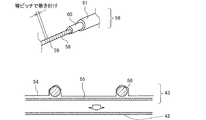
- FIG. 10 is a schematic view showing the cross section around the aluminum foil heater 43 constituting the partition plate 8 of the refrigerator 100 according to the first embodiment and the details of the cord-shaped heater 56.
- the upper side of FIG. 10 is a cross section around the aluminum foil heater 43, and the lower side of FIG. 10 is a schematic view showing details of the cord-shaped heater 56.
- the aluminum foil heater 43 is composed of a cord-shaped heater 56, an aluminum foil 54 for fixing the cord-shaped heater 56, and a double-sided tape 55, and is attached to the back side of the surface sheet metal 42 with the double-sided tape 55.
- the cord-shaped heater 56 is a cord in which a heating wire 59 such as a nichrome wire is wound around a core material 58 such as glass fiber at an equal pitch and is double-coated with insulating coating materials 60 and 61 such as polyvinyl chloride. It is a shaped heater.
- the cord-shaped heater 56 does not have to wind the heating wires 59 around the core material 58 at exactly equal pitches, and may wrap the heating wires 59 around the core material 58 at substantially equal pitches. Further, instead of the double-sided tape 55, the aluminum foil heater 43 may be glued and attached to the back side of the surface sheet metal 42.
- the cord-shaped heater 56 changes the winding pitch of the heating wire 59, for example, by changing the winding pitch of the upper part, the lower part, and the central part of the partition plate 8 to change the amount of heat generated at the portion of the partition plate 8. It is even better to use a variable pitch heater.
- the variable pitch heater requires a device capable of changing the speed at which the core wire is sent in manufacturing, and the manufacturing time is long, so that the cost is high. Therefore, it is better to decide whether or not to mount the variable pitch heater in consideration of cost performance.
- FIG. 11 is a view of the refrigerator 100 left door 6 and the partition plate 8 of the refrigerator 100 according to the first embodiment as viewed from the inside of the refrigerator.
- FIG. 12 is an enlarged view of a portion A in FIG.
- FIG. 13 is an enlarged view of a portion B of FIG.
- the partition plate 8 is attached to the double door with the upper hinge member 49 provided on the upper part of the partition plate 8 and the lower hinge provided on the lower part of the partition plate 8.
- the member 51 is fixed to the inner plate 87, which is the inner surface of the double door, with screws 46 so that the centers of the vertical rotation shafts 66, that is, the centers of the shaft shape portions 78 and 82 coincide with each other.
- the upper hinge member 49 and the lower hinge member 51 of the partition plate 8 are fixed to the inner plate 87 of the left door 6 of the refrigerator compartment with screws 46, respectively. Therefore, the partition plate 8 is adapted to rotate around the shaft-shaped portions 78 and 82.
- the main body 8a of the partition plate 8 is a portion that is not fixed to the inner plate 87 of the left door 6 of the refrigerator compartment. Then, the main body 8a of the partition plate 8 is attached to the upper hinge member 49 and the lower hinge member 51 in a state where the upper hinge member 49 and the lower hinge member 51 are fixed to the inner plate 87 of the refrigerating chamber left door 6. On the other hand, it is possible to move in the vertical direction.
- the upper hinge member 49 and the lower hinge member 51 are provided with arms 77 and 81 so as to extend from the inner plate 87 side of the refrigerating chamber left door 6 to the upper cover member 48 and the lower cover member 50 side.
- Cylindrical shaft-shaped portions 78 and 82 are provided at the ends of the arm portions 77 and 81, respectively.
- the shaft-shaped portion 78 extends downward
- the shaft-shaped portion 82 extends upward. Then, they are fitted with the tubular tube receiving shape portions 79 and 83 formed on the upper and lower sides of the resin member 53 on the back surface side of the partition plate 8, respectively.
- FIGS. 12 and 13 the portion of the shaft shape portions 78 and 82 that wraps with the cylinder receiving shape portions 79 and 83 is indicated by a broken line. Further, clearances 80 and 84 are formed between the arm portion 77 of the upper hinge member 49 and the back side resin member 53, and between the arm portion 81 of the lower hinge member 51 and the back surface side resin member 53, respectively. Has been done.
- FIG. 14 is a vertical cross-sectional view of the rotation axis 66 of FIG.
- FIG. 15 is an enlarged view of the vicinity of the lower hinge member 51 of the partition plate 8 when the left door 6 of the refrigerator 100 of the refrigerator 100 according to the first embodiment is open.
- FIG. 16 is an enlarged view of the vicinity of the lower hinge member 51 of the partition plate 8 while the left door 6 of the refrigerator 100 of the refrigerator 100 according to the first embodiment is being opened and closed.
- FIG. 17 is an enlarged view of the vicinity of the lower hinge member 51 of the partition plate 8 in the closed state of the left door 6 of the refrigerator 100 of the refrigerator 100 according to the first embodiment.
- the lower hinge member 51 is fixed to the inner plate 87 with screws 46 so that the fixing surface 106 thereof faces the inner plate 87 of the left door 6 of the refrigerator compartment. ing.
- the shaft-shaped portion 82 of the lower hinge member 51 is provided with a pin 107 projecting outward in the radial direction thereof.
- a spring 102 is housed inside the shaft-shaped portion 82 of the lower hinge member 51.
- the spring 102 is covered with a cylinder receiving shape portion 83 provided under the resin member 53 on the back surface side. Therefore, in the partition plate 8, the main body 8a is pushed upward by the reaction force of the spring 102. Then, the clearance 80 between the arm portion 77 of the upper hinge member 49 and the back side resin member 53 and the clearance 84 between the arm portion 81 of the lower hinge member 51 and the back side resin member 53 are narrowed by that amount. Only the upper end surface of the main body 8a, that is, the upper end surface 72 of the partition plate 8 moves upward.
- the guide groove 108 in which the pin 107 is housed is spirally formed in the cylinder receiving shape portion 83 so that the partition plate 8 can move up and down in the rotation axis 66 direction by rotating.
- the guide groove 108 does not have to be formed in a strictly spiral shape.
- the guide groove 108 is composed of a first groove 108a, a second groove 108b, and a third groove 108c.
- the first groove 108a is formed at a position where the pin 107 is accommodated when the left door 6 of the refrigerating chamber is open
- the second groove 108b is formed at a position where the pin 107 is accommodated when the left door 6 of the refrigerating chamber is closed.
- the first groove 108a is formed at a position higher than the second groove 108b. Therefore, a stroke 114, which is the difference in height between the first groove 108a and the second groove 108b, is formed between the upper end of the first groove 108a and the upper end of the first groove 108a in the vertical direction or the vertical direction. There is. Further, a third groove 108c is formed so as to be inclined between the first groove 108a and the second groove 108b, and the first groove 108a and the second groove 108b are connected by the third groove 108c. The third groove 108c becomes longer by the amount that the first groove 108a and the second groove 108b are shifted in the horizontal direction or the lateral direction.
- the guide groove 108 includes the first groove 108a and the second groove 108b, which are two grooves formed so as to be displaced in the vertical direction and the horizontal direction, and the third groove 108c, which is an inclined groove connecting the two grooves. It is composed of.
- the refrigerating chamber left door 6 is in the open state, and the pin 107 is in a position where it fits in the first groove 108a formed at the highest position in the guide groove 108.
- the left door 6 of the refrigerator compartment is in the process of being closed, and the pin 107 is located in the third groove 108c formed at a position lower than the first groove 108a and higher than the second groove 108b.
- the refrigerating chamber left door 6 is in the closed state, and the pin 107 is located in the second groove 108b formed at the lowest position in the guide groove 108.
- FIG. 18 is an enlarged view of the vicinity of the upper cover member 48 of the partition plate 8 showing a state in which the left door 6 of the refrigerator 100 of the refrigerator 100 according to the first embodiment is closed.
- FIG. 19 is a view of the upper cross section of the refrigerator 100 shown in FIG. 18 as viewed from below.
- FIG. 20 is a view showing a state in which the left door 6 of the refrigerator compartment is further closed as compared with FIG.
- FIG. 21 is a view showing a state in which the left door 6 of the refrigerator compartment is further closed as compared with FIG. Note that FIG. 21 shows a state in which the left door 6 of the refrigerator compartment is completely closed.
- a guide member 71 that guides the rotation of the main body 8a of the partition plate 8 when the left door 6 of the refrigerating chamber 6 is opened and closed is attached to the center of the lower front part of the ceiling 69 of the refrigerating chamber 1.
- the guide member 71 is provided with a guide protrusion 110 projecting downward.
- the guide protrusion 110 is interlocked with the opening and closing of the refrigerating room left door 6, and when the refrigerating room left door 6 is opened and closed, the refrigerating room left door 6 is in contact with the guide protrusion guide recess 109 formed in the upper cover member 48.
- the main body 8a of the partition plate 8 is rotated along the inner plate 87 of the partition plate 8.
- the cylinder receiving shape portion 83 moves with respect to the pin 107, and the position of the pin 107 is relatively in the order of the first groove 108a, the third groove 108c, and the second groove 108b in the guide groove 108, that is, the lower groove. Move in the direction of. Then, when the left door 6 of the refrigerator compartment is completely closed, the pin 107 is in a position where it fits in the second groove 108b, as shown in FIG. At this time, in the first groove 108a and the second groove 108b, the second groove 108b is at a lower position.
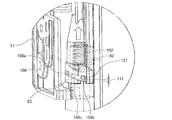
- FIG. 22 is an enlarged view of a portion C in FIG. In FIG. 22, some parts are shown by broken lines so that the internal structure of the lower hinge member 51 of the partition plate 8 can be seen.
- the necessity of the spring 102 housed inside the shaft-shaped portion 82 of the lower hinge member 51 will be described.
- the position of the left door 6 of the refrigerating room is lowered due to aged deterioration or food or the like is stored in the pocket 26 attached to the left door 6 of the refrigerating room. It goes down against the ceiling 69. Therefore, an upper gap is formed between the upper end surface 72 of the partition plate 8 and the flat lower surface 73 of the guide member 71 provided on the ceiling 69 of the refrigerating chamber 1.
- the position of the main body 8a of the partition plate 8 is changed by the spring 102 so that the main body 8a of the partition plate 8 can be moved upward.
- the upper end surface 72 of the partition plate 8 and the flat lower surface 73 of the guide member 71 provided on the ceiling 69 of the refrigerating chamber 1 come into contact with each other, and an upper gap is not formed.
- the guide groove 108 is formed in the cylinder receiving shape portion 83 provided in the lower part of the resin member 53 on the back side of the partition plate 8, and the pin 107 is in the middle of the first groove 108a to the third groove 108c.
- the pin 107 is located at the lower end of the guide groove 108 when it is between. Further, when the pin 107 crosses the middle of the third groove 108c, the pin 107 separates from the lower end of the guide groove 108.
- the pin 107 is in the second groove 108b, the pin 107 is located at a position having a slight stroke 111 from the lower end of the guide groove 108.
- the stroke 111 is a gap between the lower end of the pin 107 and the lower end of the second groove 108b.
- the spring 102 is extended so that the partition plate 8 is provided on the ceiling 69 of the refrigerating room 1 for this stroke 111 minutes.
- the guide member 71 can be brought into contact with the flat lower surface 73 so as to follow it. Further, the stroke 111 can absorb the variation in the mounting position of the partition plate 8 or the variation in the total length dimension of the partition plate 8. Therefore, regardless of the product variation, the upper end surface 72 of the partition plate 8 and the flat lower surface 73 of the guide member 71 provided on the ceiling 69 of the refrigerating chamber 1 can be stably brought into contact with each other.
- the stroke 111 is about 1 mm, which is smaller than the height difference between the first groove 108a and the second groove 108b, that is, the stroke 114 (see FIG. 16). By doing so, it is possible to suppress a collision of the refrigerator 100 with the housing 101 when the main body 8a of the partition plate 8 is rotated by opening and closing the left door 6 of the refrigerator compartment. Further, when the left door 6 of the refrigerating chamber 6 is opened and closed, the upper end surface 72 of the partition plate 8 can be brought into contact with the flat lower surface 73 of the guide member 71 provided on the ceiling 69 of the refrigerating chamber 1.
- the energization rate calculation formula determined in advance by a test or the like is programmed in the control device 29.
- the energization rate is defined by changing the voltage applied to the aluminum foil heater 43 over time, for example, energizing for 5 seconds within a predetermined time of 10 seconds and not energizing the remaining 5 seconds. In this case, the energization rate is 50%.
- the energization rate of the aluminum foil heater 43 is calculated by the control device 29 according to the outside air temperature, the outside air humidity, and the refrigerating room temperature, and changes according to the surrounding environment.
- the control device 29 calculates the energization rate calculation formula according to the outside air temperature, the outside air humidity, and the refrigerating room temperature detected by the outside air temperature sensor 9, the outside air humidity sensor 10, and the refrigerating room temperature sensor 32. Then, the energization rate of the aluminum foil heater 43 is determined.
- the determined energization rate is the energization rate at which dew does not adhere to the surface of the partition plate 8, the periphery of the refrigerating room left door 6 and the refrigerating room right door 7, or the gaskets 62, 64 and the gasket fins 63, 65, 75, 76. That is, it is an energization rate that improves the dew resistance and prevents dew condensation.
- the energization rate calculated from the energization rate calculation formula is such that the higher the outside air temperature and the outside air humidity, the higher the energization rate, and the lower the temperature of the refrigerating chamber 1, the higher the energization rate. Then, the control device 29 energizes the aluminum foil heater 43 at the energization rate determined by calculation. Therefore, if the outside air temperature and the outside air humidity are low and the refrigerating room temperature is high, the energization rate can be reduced, and the energy efficiency can be improved.
- FIG. 23 is a cross-sectional view taken along the line DD of FIG.
- FIG. 24 is a cross-sectional arrow view at the same position as FIG. 23 of the conventional refrigerator.
- the temperature of the gasket fins 63 and 65 is higher. It depends on the temperature of the gap 67.
- the upper end surface 72 of the partition plate 8 is provided on the ceiling 69 of the refrigerating chamber 1 by the reaction force 112 of the spring 102. It comes into contact with the flat lower surface 73 of the guide member 71. Then, the upper end surface 72 of the partition plate 8 comes into contact with the flat lower surface 73 of the guide member 71 provided on the ceiling 69 of the refrigerating chamber 1, so that the upper gap 67 is eliminated. Therefore, it is possible to prevent cold air from directly hitting the back surfaces of the gasket fins 63 and 65, and it is possible to raise the surface temperature of the gasket fins 63 and 65. Can be done and energy efficiency can be improved.
- the configuration of the partition plate 8, the method of energizing the aluminum foil heater 43, the energization rate calculation formula, and the like are not limited to the above contents.
- the partition plate 8 may be configured without the surface frame type resin member 44.
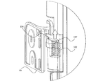
- FIG. 25 is an enlarged perspective view of the periphery of the upper hinge member 49 according to the modified example of the refrigerator 100 according to the first embodiment. In FIG. 25, some parts are shown by broken lines so that the internal structure of the upper hinge member 49 of the partition plate 8 can be seen.
- a mechanism having a pin 107 and a guide groove 108 is provided, but the present invention is not limited thereto.
- a mechanism having a spring 102, a pin 107, and a guide groove 108 may be provided on the upper part of the partition plate 8 as shown in FIG. , The same effect can be obtained by doing so.
- the refrigerator 100 has an outer shell, a housing 101 having a refrigerating chamber 1 inside, and a housing 101 provided on the front surface of the housing 101 to open and close the front opening of the refrigerating chamber 1.
- a partition plate 8 that is rotatably attached to one of the left and right double doors and one of the left and right double doors to prevent outside air from entering the refrigerator compartment 1, and the lower front part of the ceiling 69 of the refrigerator compartment 1.
- the guide member 71 provided in the above is provided.
- the partition plate 8 is provided on the upper and lower sides and is supported by the upper hinge member 49 and the lower hinge member 51 fixed to the inner surface of the double door, and the upper hinge member 49 and the lower hinge member 51, and the partition plate 8 is supported.
- a main body portion 8a that is guided by a guide member 71 and rotates when the double door is opened and closed.
- the main body 8a moves upward as compared with the open door, and the upper end surface of the main body 8a is moved upward.
- 72 is in contact with the lower surface 73 of the guide member 71.
- the main body 8a moves upward as compared with the state where the double door is open. Therefore, since the upper end surface 72 of the main body 8a is in contact with the lower surface 73 of the guide member 71, the upper end surface 72 of the partition plate 8 and the upper front surface of the refrigerator compartment 1 are in a state where the double door is closed. The gap between the opening and the opening can be reduced. Further, since the ball casters and the guide rails are not required, it is possible to suppress the deterioration of usability. Further, packing or the like is not required on the upper end surface 72 of the partition plate 8, and deterioration of the operability of the partition plate 8 can be suppressed.
- the space between the upper end surface 72 of the partition plate 8 and the lower surface 73 of the guide member 71 can be closed, it is possible to prevent the gap and prevent cold air from directly hitting the back surfaces of the gasket fins 63 and 65.
- the surface temperature of the gasket fins 63 and 65 can be raised. Therefore, the energization rate, which is higher than necessary, can be lowered, and the energy efficiency can be improved.
- the spring 102 is housed inside the shaft shape portion 82, and the spring 102 is covered with the cylinder receiving shape portion 83. Then, when closing the double door to which the partition plate 8 is attached, the pin 107 moves lower in the guide groove 108 as it rotates around the shaft-shaped portion 82, and the reaction force of the spring 102 causes the main body. The upper end surface 72 of the portion 8a moves upward.
- the upper end surface 72 of the partition plate 8 and the flat lower surface 73 of the guide member 71 provided on the ceiling 69 of the refrigerating chamber 1 are stably pressed regardless of the product variation. Can be touched.
- Embodiment 2 Hereinafter, the second embodiment will be described, but the description of the parts overlapping with the first embodiment will be omitted, and the same parts or the corresponding parts as those of the first embodiment will be designated by the same reference numerals.
- FIG. 26 is a vertical sectional view of the refrigerator 100 according to the second embodiment. Note that FIG. 26 is a cross-sectional arrow view at the same position as FIG. 23 of the first embodiment.
- the pin 107 is not provided in the shaft shape portion 82 of the lower hinge member 51, and the cylinder receiving shape portion 83 provided in the lower part of the back surface side resin member 53.
- the guide groove 108 is not formed in the.
- the magnet 113 is provided inside the guide member 71. Further, a screw 46 for fixing the upper cover member 48 is arranged on the upper end surface 72 of the partition plate 8. Then, the screw 46 arranged on the upper end surface 72 of the partition plate 8 is attracted by the magnetic force of the magnet 113 provided inside the guide member 71, and the main body portion 8a of the partition plate 8 is moved upward. By doing so, when the left door 6 of the refrigerating chamber is closed, the upper end surface 72 of the partition plate 8 and the flat lower surface 73 of the guide member 71 provided on the ceiling 69 of the refrigerating chamber 1 are brought into contact with each other.
- the clearances 80 and 84 between the arms 77 and 81 of the upper hinge member 49 and the lower hinge member 51 and the back resin member 53 shown in FIGS. 12 and 13 are set as play dimensions.
- the resin member 53 on the back side of the partition plate 8 moves downward due to gravity, and the lower end surface of the cylinder receiving shape portion 83 provided under the resin member 53 on the back side of the partition plate 8 is provided. Is in a state of being on the arm 81 of the lower hinge member 51.
- FIG. 27 is an enlarged perspective view of the upper part of the partition plate 8 according to the modified example of the refrigerator 100 according to the second embodiment.
- a bent portion 42a is formed on the upper end surface 72 of the partition plate 8 instead of the screw 46, and the bent portion 42a is fixed to the upper end surface 72 of the partition plate 8. .. Then, the bent portion 42a of the surface sheet metal 42 may be attracted by the magnetic force of the magnet 113 inside the guide member 71.
- the upper end portion of the surface sheet metal 42 is a guide protrusion guide recess 109 of the upper cover member 48 in which the upper end portion of the surface sheet metal 42 is rotated by the guide protrusion 110 to some extent from the surface side of the upper end surface 72 of the partition plate 8. It is formed by bending it to the front.
- the main body 8a of the partition plate 8 rotates according to the opening and closing of the left door 6 of the refrigerating chamber, and when the left door 6 of the refrigerating chamber is closed, the upper end surface 72 of the partition plate 8 is formed.
- the upper gap 67 is eliminated by contacting the flat lower surface 73 of the guide member 71 provided on the ceiling 69 of the refrigerator compartment 1. Therefore, it is possible to prevent cold air from directly hitting the back surfaces of the gasket fins 63 and 65, and it is possible to raise the surface temperature of the gasket fins 63 and 65. Can be done and energy efficiency can be improved.
- the screw 46 is arranged on the upper end surface 72 of the main body 8a, and the magnet 113 is provided inside the guide member 71.
- the screw 46 is attracted to the magnet 113 as compared with the open door, and the upper end surface 72 of the main body 8a Is in contact with the lower surface 73 of the guide member 71.
- the main body 8a has a metal surface sheet metal 42 located on the surface side, and the surface sheet metal 42 has a bent portion 42a whose upper end is bent.
- a bent portion 42a of the surface sheet metal 42 is arranged on the upper end surface 72 of the main body portion 8a, and a magnet 113 is provided inside the guide member 71.
- the screw 46 is attracted to the magnet 113 as compared with the state where the double door is open.
- the upper end surface 72 of the main body 8a is in contact with the lower surface 73 of the guide member 71.
- the bent portion 42a is attracted to the magnet 113 as compared with the open state of the double door, and the upper end surface of the main body 8a is attracted.
- 72 is in contact with the lower surface 73 of the guide member 71. Therefore, when the double door is closed, the gap between the upper end surface 72 of the partition plate 8 and the upper front opening of the refrigerator compartment 1 can be reduced.
- the ball casters and the guide rails are not required, it is possible to suppress the deterioration of usability. Further, packing or the like is not required on the upper end surface 72 of the partition plate 8, and deterioration of the operability of the partition plate 8 can be suppressed. Further, since the space between the upper end surface 72 of the partition plate 8 and the lower surface 73 of the guide member 71 can be closed, it is possible to prevent the gap and prevent cold air from directly hitting the back surfaces of the gasket fins 63 and 65. The surface temperature of the gasket fins 63 and 65 can be raised. Therefore, the energization rate, which is higher than necessary, can be lowered, and the energy efficiency can be improved.
- Embodiment 3 Hereinafter, the third embodiment will be described, but the description of the parts overlapping with the first embodiment will be omitted, and the same parts or the corresponding parts as those of the first embodiment will be designated by the same reference numerals.
- the hinge structure of the refrigerator compartment door has been strengthened to the extent that the position of the refrigerator compartment left door 6 does not move even if food or the like is stored in the pocket 26 attached to the refrigerator compartment left door 6 due to aged deterioration.
- the distance between the upper end surface 72 of the partition plate 8 and the ceiling 69 of the refrigerator compartment 1 is constant. Therefore, by strengthening the hinge structure of the refrigerator compartment door to the extent that the position of the refrigerator compartment left door 6 does not move down, a push-up structure by the reaction force of the spring 102 or a pull-in structure by the magnetic force of the magnet 113 becomes unnecessary, and the cost is reduced. Can be reduced.
- the pin 107 moves in the guide groove 108 to cause the refrigerating chamber left door 6 to move.
- the main body 8a of the partition plate 8 moves up and down according to the opening and closing.
- a member that assists the vertical movement of a part of the partition plate 8 such as the spring 102 described in the first embodiment and the magnet 113 described in the second embodiment (hereinafter, vertical movement). It does not have an auxiliary member). Therefore, when the left door 6 of the refrigerator compartment is opened, the main body 8a of the partition plate 8 rotates while the pin 107 and the guide groove 108 are in contact with each other due to its own weight.
- a mechanism having a pin 107 and a guide groove 108 may be provided in the upper part of the partition plate 8 in addition to the lower part of the partition plate 8 or in place of the lower part of the partition plate 8, and the same effect can be obtained by doing so. Be done.
Landscapes
- Engineering & Computer Science (AREA)
- Chemical & Material Sciences (AREA)
- Combustion & Propulsion (AREA)
- Physics & Mathematics (AREA)
- Mechanical Engineering (AREA)
- Thermal Sciences (AREA)
- General Engineering & Computer Science (AREA)
- Refrigerator Housings (AREA)
Abstract
冷蔵庫は、外郭を構成し、内部に冷蔵室が設けられた筐体と、筐体の前面に設けられ、冷蔵室の前面開口部を開閉する左右の観音開き式扉と、左右の観音開き式扉のうちの一方に回動可能に取り付けられて冷蔵室内に外気が侵入するのを防ぐ仕切板と、冷蔵室の天井の前方下部に設けられたガイド部材と、を備え、仕切板は、上下に設けられ、観音開き式扉の内面に固定される上側ヒンジ部材および下側ヒンジ部材と、上側ヒンジ部材および下側ヒンジ部材に支持され、仕切板が取り付けられた観音開き式扉の開閉時にガイド部材にガイドされて回動する本体部と、を備え、仕切板が取り付けられた観音開き式扉が閉じられた状態では、該観音開き式扉の開いている状態に比べて、本体部が上方向に移動しており、本体部の上端面がガイド部材の下面と当接しているものである。
Description
本開示は、観音開き式扉を備えた冷蔵庫に関するものである。
近年、冷蔵庫が設置される環境に合わせて最適な運転を実現させるために、温度センサおよび湿度センサなどが搭載される冷蔵庫が増えてきている。例えば、冷蔵室扉が左右に分割されていて、その冷蔵室扉間の仕切板にヒータなどが設置され、周囲の室温および湿度に合わせてヒータへの通電を時間割合で変化させることで、仕切板の表面温度を調節してエネルギー効率を高めるような冷蔵庫がある。
また、仕切板は通常、左右の冷蔵室扉のどちらか一方に取り付けられ、その上部および下部で冷蔵室扉にヒンジ固定され、冷蔵室の上部に設置されたガイド部品の突起により、冷蔵室扉を開閉するときに回動する構造が採用されている。
また、仕切板と冷蔵室の開口部との接触を防止して冷蔵室扉をスムーズに回動させるために、冷蔵室の開口部の高さよりも仕切板の長手方向の長さを短くし、仕切板と冷蔵室の開口部との間にある程度の隙間が上下に形成されるように仕切板が設置される。そして、その上下の隙間を塞ぐために左右の冷蔵室扉のガスケットの上下部分にガスケットヒレを設け、左右の冷蔵室扉が閉じられている状態では、その左右のガスケットヒレが重なり合うことで、隙間が塞がれるようになっている。
ここで、上下のガスケットヒレの裏側には冷蔵室の冷気が直接当たっており、冷蔵室の上側では下側よりも風量が多くなるように設定されるため、上側のガスケットヒレは露がつきやすい。そして、上側のガスケットヒレに露がつきにくくするためには、ガスケットヒレを加熱する、または冷却されないようにすればよい。加熱する手段として仕切板内のヒータの発熱量を上げればよいが、単に発熱量を上げることはエネルギー効率を下げてしまう恐れがあるので、冷却されない手段を検討する必要がある。ここで、ガスケットヒレが冷却されない手段として、ガスケットヒレの裏面に冷蔵室の冷気が直接当たらないようにする、あるいは冷気が直接当たる量を減らせばよいが、その方法の一つとして、仕切板の上端面と冷蔵室の前面開口部との間の隙間を減らすことが考えられる。
従来、開閉時に観音式扉の位置をコントロールすることで、観音式扉と冷蔵庫の筐体との隙間をなくす技術が報告されている(例えば、特許文献1参照)。
特許文献1では、観音開き式扉の中央寄り下面にボールキャスタを設置するとともに、そのボールキャスタに対向して冷蔵庫の筐体の下部前面には観音開き式扉を閉じた際にボールキャスタを乗り上げて観音開き式扉を定位置に担持するガイドレールを敷設する技術が報告されている。この技術によれば、観音開き式扉と冷蔵庫の筐体との間に隙間を残すことなく観音開き式扉を正常に閉じることができる。
しかしながら、特許文献1では、観音開き式扉が閉じられた状態において、仕切板の上端面と冷蔵室の上側の前面開口部との間の隙間を減らせるかは定かではない。また、仕切板の下面にボールキャスタが設置され、また、冷蔵室の床面にガイドレールが設置されるので、冷蔵室が冷蔵庫の最上段に設置される冷蔵庫においては、ボールキャスタおよびガイドレールが邪魔となり、使い勝手が悪いという課題があった。
本開示は、以上のような課題を解決するためになされたもので、観音開き式扉が閉じられた状態における仕切板の上端面と冷蔵室の上側の前面開口部との間の隙間を減らしつつ、使い勝手の低下を抑制することができる冷蔵庫を提供することを目的としている。
本開示に係る冷蔵庫は、外郭を構成し、内部に冷蔵室が設けられた筐体と、前記筐体の前面に設けられ、前記冷蔵室の前面開口部を開閉する左右の観音開き式扉と、左右の前記観音開き式扉のうちの一方に回動可能に取り付けられて前記冷蔵室内に外気が侵入するのを防ぐ仕切板と、前記冷蔵室の天井の前方下部に設けられたガイド部材と、を備え、前記仕切板は、上下に設けられ、前記観音開き式扉の内面に固定される上側ヒンジ部材および下側ヒンジ部材と、前記上側ヒンジ部材および前記下側ヒンジ部材に支持され、前記仕切板が取り付けられた前記観音開き式扉の開閉時に前記ガイド部材にガイドされて回動する本体部と、を備え、前記仕切板が取り付けられた前記観音開き式扉が閉じられた状態では、該観音開き式扉の開いている状態に比べて、前記本体部が上方向に移動しており、前記本体部の上端面が前記ガイド部材の下面と当接しているものである。
本開示に係る冷蔵庫によれば、仕切板が取り付けられた観音開き式扉が閉じられた状態では、該観音開き式扉の開いている状態に比べて、本体部が上方向に移動しており、本体部の上端面が前記ガイド部材の下面と当接している。そのため、観音開き式扉が閉じられた状態において、仕切板の上端面と冷蔵室の上側の前面開口部との間の隙間を減らすことができる。また、ボールキャスタおよびガイドレールは不要であるため、使い勝手の低下を抑制することができる。
以下、実施の形態を図面に基づいて説明する。なお、以下に説明する内容によって実施の形態が限定されるものではない。また、以下の図面では各構成部材の大きさの関係が実際のものとは異なる場合がある。
実施の形態1.
図1は、実施の形態1に係る冷蔵庫100の正面図である。図2は、実施の形態1に係る冷蔵庫100を上方から見た斜視図である。
以下、実施の形態1に係る冷蔵庫100の構成について説明する。以下の説明において、理解を容易にするために方向を表す用語、例えば「上」、「下」、「右」、「左」、「前」、「後」など、を適宜用いるが、これらは説明のためのものであって、これらの用語は実施の形態を限定するものではない。また、実施の形態1では、冷蔵庫100を正面視した状態において、「上」、「下」、「右」、「左」、「前」、「後」などを使用する。
図1は、実施の形態1に係る冷蔵庫100の正面図である。図2は、実施の形態1に係る冷蔵庫100を上方から見た斜視図である。
以下、実施の形態1に係る冷蔵庫100の構成について説明する。以下の説明において、理解を容易にするために方向を表す用語、例えば「上」、「下」、「右」、「左」、「前」、「後」など、を適宜用いるが、これらは説明のためのものであって、これらの用語は実施の形態を限定するものではない。また、実施の形態1では、冷蔵庫100を正面視した状態において、「上」、「下」、「右」、「左」、「前」、「後」などを使用する。
図1および図2に示すように、実施の形態1に係る冷蔵庫100は、外郭を構成する筐体101を備え、筐体101の内部には、複数の貯蔵室が設けられている。具体的には、貯蔵室として、冷蔵室1と、製氷室2と、小型冷凍室3と、冷凍室4と、野菜室5とが設けられている。冷蔵室1は、冷蔵庫100の最上段に設けられており、前面開口部が2枚の観音開き式扉で開閉自在に閉塞されている。この2枚の観音開き式扉は、筐体101の前面に設けられている。また、この2枚の観音開き式扉は、冷蔵室左扉6と冷蔵室右扉7とで構成されており、冷蔵室左扉6と冷蔵室右扉7との間には、その間からの外気の侵入を防ぐ仕切板8が設けられている。なお、仕切板8の詳細については後述する。
冷蔵室1の下方には、引出扉(図示せず)を引き出すと貯蔵室が使用者側に引き出される製氷室2および小型冷凍室3が並列に配置されている。また、冷蔵庫100の最下段には野菜室5が設けられており、野菜室5の上には冷凍室4が設けられている。この冷凍室4は、左右に並列に配置された製氷室2および小型冷凍室3の下方で、かつ、野菜室5の上方に設けられている。これら冷凍室4および野菜室5も、引出扉(図示せず)を引き出すと貯蔵室が使用者側に引き出される構成となっている。
なお、各貯蔵室の配置は実施の形態1に限定されるものではなく、2枚の観音開き式扉を備え、その扉間に仕切板8が設けられた構成であれば、各貯蔵室の配置は問わない。また、冷蔵庫100には、外気温度センサ9および外気湿度センサ10が搭載されている。外気温度センサ9は、冷蔵庫100の外部の空気温度である外気温度を検知するものである。外気湿度センサ10は、冷蔵庫100の外部の空気湿度である外気湿度を検知するものである。
なお、外気温度センサ9および外気湿度センサ10は、外気温度および外気湿度を検知できる位置であれば設置場所は問わない。ただし、外気温度センサ9および外気湿度センサ10は、冷蔵庫100の運転に影響されない位置、例えば側面内側に貼り付け固定された側面凝縮配管の温度影響などに影響されない位置に設置するのが望ましい。そのため、外気温度センサ9および外気湿度センサ10の設置場所は、例えば冷蔵室左扉6の上側に設けられたヒンジカバー部材11内であれば、その凝縮パイプなどの熱影響を受けないのでよい。
図3は、実施の形態1に係る冷蔵庫100の冷蔵室左扉6の構成を示す分解斜視図である。図4は、実施の形態1に係る冷蔵庫100の冷蔵室右扉7の構成を示す分解斜視図である。
ここで、図3および図4に示す観音開き式扉について説明する。冷蔵室左扉6および冷蔵室右扉7は、上下左右が樹脂製のキャップ部品96、97で構成され、扉内面が樹脂製の内板87、88で構成され、扉表面がガラス製の扉表面パネル98、99で構成されている。つまり、冷蔵室左扉6および冷蔵室右扉7は、キャップ部品96、97、内板87、88、および、扉表面パネル98、99で6面が構成されている。また、冷蔵室左扉6および冷蔵室右扉7の内部には、ウレタン発泡の断熱材(図示せず)が充填されている。また、冷蔵室左扉6には、冷蔵室右扉7との間を塞ぐための仕切板8が、内板87の中央側側面に扉開閉時に回動するようその上下部にてヒンジ固定されている。
ここで、図3および図4に示す観音開き式扉について説明する。冷蔵室左扉6および冷蔵室右扉7は、上下左右が樹脂製のキャップ部品96、97で構成され、扉内面が樹脂製の内板87、88で構成され、扉表面がガラス製の扉表面パネル98、99で構成されている。つまり、冷蔵室左扉6および冷蔵室右扉7は、キャップ部品96、97、内板87、88、および、扉表面パネル98、99で6面が構成されている。また、冷蔵室左扉6および冷蔵室右扉7の内部には、ウレタン発泡の断熱材(図示せず)が充填されている。また、冷蔵室左扉6には、冷蔵室右扉7との間を塞ぐための仕切板8が、内板87の中央側側面に扉開閉時に回動するようその上下部にてヒンジ固定されている。
また、使用者が各貯蔵室の温度設定を操作したり、省エネモードおよび露付き対策モードなどのモード設定を操作したりできるような設定操作部103が冷蔵室左扉6に設けられている。なお、仕切板8および設定操作部103は、冷蔵室右扉7に設けられていてもよい。
ここで、冷蔵室左扉6および冷蔵室右扉7には、磁石(図示せず)を内封したガスケット62、64が取り付けられている。そして、ガスケット62、64は、冷蔵室1の前面開口部の周りの前面フランジ部70(後述する図6および図7参照)、および、仕切板8に密着するようになっている。各ガスケット62、64の仕切板8と密着する側の縦辺、つまり、ガスケット62の右側縦辺の上部および下部、および、ガスケット64の左側縦辺の上部および下部には、ガスケットヒレ63、75、65、76がそれぞれ設けられている。そして、冷蔵室左扉6および冷蔵室右扉7が両方とも閉まっている状態において、上側のガスケットヒレ63とガスケットヒレ65とは、仕切板8および冷蔵室1の前面フランジ部70に密着し、後述する仕切板8の上端面72と冷蔵室1の天井69に設けられたガイド部材71の平らな下面73との接触面を塞ぐようになっている(後述する図18参照)。また、下側のガスケットヒレ75とガスケットヒレ76とは、仕切板8および冷蔵室1の前面フランジ部70に密着し、後述する仕切板8の下端と冷蔵室1下面との間に形成された隙間(以下、下部隙間と称する)を塞ぐようになっている。
また、冷蔵室左扉6および冷蔵室右扉7の庫内側には、高さ方向に沿って収納用の3つのポケット26が取り付けられている。なお、冷蔵室左扉6および冷蔵室右扉7に取り付けられているポケット26の数は、それぞれ3つに限定されず、2つ以下でも4つ以上でもよい。
図5は、実施の形態1に係る冷蔵庫100の冷媒回路104を示す図である。図6は、実施の形態1に係る冷蔵庫100内部の冷媒配管の接続図である。図7は、実施の形態1に係る冷蔵庫100内部の変形例による冷媒配管の接続図である。なお、図5に示す矢印は、冷媒の流れを示している。また、図6および図7では、右手前側が冷蔵庫100の前側である。
実施の形態1に係る冷蔵庫100は、冷媒が循環する冷媒回路104を備えている。その冷媒回路104は、図5に示すように、圧縮機12、フィンチューブ式の機械室凝縮器13、左側側面凝縮配管14、天井面凝縮配管15、背面凝縮配管16、右側側面凝縮配管17、露付き防止配管18、ドライヤ19、減圧装置である毛細管20、冷却器21、マフラー(液溜め)22、および、吸入配管23を備えている。ここで、機械室凝縮器13、左側側面凝縮配管14、天井面凝縮配管15、背面凝縮配管16、右側側面凝縮配管17、および、露付き防止配管18は、凝縮系配管である。
図6に示すように、圧縮機12、機械室凝縮器13、および、ドライヤ19は、冷蔵庫100の背面側下部に設けられた機械室(図示せず)に設置されている。また、天井面凝縮配管15は、左側側面の左側側面凝縮配管14から天井面へ延出してつながっている。なお、天井面凝縮配管15は、右側側面の右側側面凝縮配管17から天井面へ延出してつなげてもよい。また、左側側面凝縮配管14、天井面凝縮配管15、背面凝縮配管16、および、右側側面凝縮配管17は、図示しないが冷蔵庫100の金属製の外箱の内面にアルミテープで固定されている。
また、冷蔵庫100は、機械室に設けられ、機械室凝縮器13および圧縮機12を冷却する機械室冷却ファン(図示せず)と、冷却器21の上方に設けられ、庫内へ冷気を循環させる庫内冷却ファン(図示せず)とを備えている。
なお、凝縮系配管を経過した後の露付き防止配管18の下流側であれば、毛細管20を2本設置したり、冷却器21を複数設置したりしてもよい。なお、毛細管20を2本設置する場合は、毛細管20の上流側に三方弁を設置する。また、機械室凝縮器13、天井面凝縮配管15、および、背面凝縮配管16は、左側側面凝縮配管14および右側側面凝縮配管17だけで凝縮能力を稼げるのであれば設けられていなくても問題ない。
図6に示すように、露付き防止配管18は、冷蔵室1、製氷室2、小型冷凍室3、冷凍室4、および、野菜室5、つまり、各貯蔵室を取り囲むように前面フランジ部70に配置されている。また、露付き防止配管18は、右奥側下で右側側面凝縮配管17に接続されており、左奥側下で機械室に配置されたドライヤ19に接続されている。
なお、冷蔵室1の壁面と外箱との間の断熱性能がよい場合は、図7に示すように、露付き防止配管18は、冷蔵室1を除く各貯蔵室を取り囲むように前面フランジ部70に配置されていてもよい。つまり、露付き防止配管18は、冷蔵室1の上側および左右の前面フランジ部70には配置しなくてもよい。ここで、冷蔵室1の壁面と外箱との間の断熱性能がよい場合とは、例えば、冷蔵室1の壁面と外箱との間の距離、つまり断熱厚さが大きい場合、または、冷蔵室1の壁面と外箱との間に真空断熱材が配置されている場合などである。
図7に示す構造では、冷蔵室1の上側および左右の前面フランジ部70には露付き防止配管18が配置されていないため、仕切板8が設置される周辺の前面フランジ部70の温度は、露付き防止配管18が配置されている場合と比較して温度は下がる。しかし、後述する仕切板8内のヒータのパターン配置によって温度がそれ以上に上昇すれば、仕切板8の上端面72と冷蔵室1の天井69に設けられたガイド部材71の平らな下面73との接触面を塞ぐガスケットヒレ63、65の温度は下がらない。そして、配置する露付き防止配管18の長さを減らすことで、材料コストおよび露付き防止配管18を配置する際にかかる製造コストを低減することができる。
図8は、実施の形態1に係る冷蔵庫100の上部の縦断面図である。
図8に示すように、冷蔵庫100の背面側には、制御装置29が設けられている。この制御装置29は、例えば、専用のハードウェア、またはメモリに格納されるプログラムを実行するCPU(Central Processing Unit、中央処理装置、処理装置、演算装置、マイクロプロセッサ、プロセッサともいう)で構成されている。
図8に示すように、冷蔵庫100の背面側には、制御装置29が設けられている。この制御装置29は、例えば、専用のハードウェア、またはメモリに格納されるプログラムを実行するCPU(Central Processing Unit、中央処理装置、処理装置、演算装置、マイクロプロセッサ、プロセッサともいう)で構成されている。
冷蔵室1内には、冷蔵室1の温度(以下、冷蔵室温度と称する)を検知するための冷蔵室温度センサ32が設けられている。この冷蔵室温度センサ32は、冷蔵室温度を検知できる位置であれば、冷蔵室1内での設置位置は問わない。制御装置29は、冷蔵室温度センサ32で検知した冷蔵室温度に基づいて、冷蔵室1への冷気の送風または遮断を、冷蔵室用ダンパー装置31のバッフル85を開閉させることで行う。ここで、冷蔵室用ダンパー装置31は、冷蔵庫100の背面側に形成された冷蔵室吹出し風路86に設けられている。なお、この冷蔵室温度センサ32は、温度補償用に冷蔵室1内に設置されたヒータ(図示せず)および、仕切板8内に設置された後述するアルミ箔ヒータ43(後述する図9参照)への通電制御などを行うために用いられる。
ここで、図8中の矢印37~41は、冷蔵室1の奥側の壁に形成された吹出し口(図示せず)からの風の流れを示し、矢印33~36は、冷蔵室1の熱の移動を示している。矢印33は、冷蔵室1の天井69からの熱侵入を示している。矢印34は、冷蔵室1の背面からの熱侵入を示している。矢印35は、冷蔵室左扉6または冷蔵室右扉7からの熱侵入を示している。矢印36は、冷蔵室1から冷蔵室1に比べて温度の低い製氷室2または小型冷凍室3への熱の移動を示している。なお、他の熱侵入に関して、冷蔵室1の側面から侵入する熱もあるが、図8は断面図であるため図示を省略する。矢印の大きさはそれぞれ風あるいは熱の量を示しており、例えば、矢印37は矢印41と比べて風量が多いことを示し、矢印33は矢印36と比べて熱移動量が多いことを示している。
冷蔵室1内は、複数の棚30によって複数に区画されている。また、冷蔵室1内の最下段の棚30の下には、冷蔵室1の温度(約3℃)より低いチルド室27(約0℃)が設けられており、チルド室27には、食品を収納するチルドケース28が設けられている。また、冷蔵室1の奥側の壁の、複数の棚30によって区画された各部分には、各吹出し口から矢印37~41で示す風が吹き出される。
ここで、図8に示すように、一般的には、冷蔵室1の上側は、冷蔵室1の天井69からの熱(矢印33参照)の漏洩が大きい。そのため、冷蔵室1の奥側の壁に形成された吹出し口から吹き出される風量に関して、冷蔵室1内を複数の棚30によって区画された各部分において、最上段の風量を最も多くしている。そして、冷蔵室1内の区画された各部分の温度分布をある程度の幅内に収めるようにしているため、仕切板8の上部は下部よりも冷やされやすい傾向にある。
そのため、従来では、上側のガスケットヒレ63、65に露が付かないように仕切板8内のアルミ箔ヒータ43への通電率を必要以上に高くしていた。また、従来では、冷蔵庫の仕切板8の上端面72と冷蔵室1の天井69に設けられたガイド部材71の平らな下面73との間に形成される隙間(以下、上部隙間と称する)を塞ぐガスケットヒレ63、65の表面温度は、冷蔵室1の上側にて風量が多いため、下部隙間を塞ぐガスケットヒレ75、76の表面温度よりも上がりにくい傾向がある。そのため、従来では、上部隙間を塞ぐガスケットヒレ63、65の表面温度に応じてアルミ箔ヒータ43への通電率が決定されていた。
図9は、実施の形態1に係る冷蔵庫100の仕切板8の分解図である。
図9に示すように、仕切板8の表面側となる金属製の表面板金42の裏側には、長手方向に沿って蛇行形状のパターンが形成されたアルミ箔ヒータ43が貼り付けられている。そして、そのアルミ箔ヒータ43の裏側には、樹脂製の表面枠型樹脂部材44が、そのツメ(図示せず)が表面板金42のツメ受け部57に嵌合することにより取り付けられている。また、仕切板8の背面側となる樹脂製の背面側樹脂部材53の上側には、軸形状部78を有する上側ヒンジ部材49が取り付けられ、さらにその上から上側カバー部材48がネジ46で固定されている。上側カバー部材48の上端面にはガイド突起案内凹部109が形成されており、後述するガイド突起110(後述する図18参照)と当接して冷蔵室左扉6の開閉に合わせて仕切板8が回動するようになっている。また、背面側樹脂部材53の下側には、軸形状部82を有する下側ヒンジ部材51が取り付けられ、さらにその下から下側カバー部材50がネジ46で固定されている。また、下側ヒンジ部材51の軸形状部82の内部には、バネ102が収納されている。また、下側ヒンジ部材51には、バネ止め47がネジ46で固定されており、そのバネ止め47にはバネ52が取り付けられている。そして、その状態の背面側樹脂部材53が、表面枠型樹脂部材44の裏側に、断熱材45を挟んで表面板金42のツメ68が嵌合することにより取り付けられている。
図9に示すように、仕切板8の表面側となる金属製の表面板金42の裏側には、長手方向に沿って蛇行形状のパターンが形成されたアルミ箔ヒータ43が貼り付けられている。そして、そのアルミ箔ヒータ43の裏側には、樹脂製の表面枠型樹脂部材44が、そのツメ(図示せず)が表面板金42のツメ受け部57に嵌合することにより取り付けられている。また、仕切板8の背面側となる樹脂製の背面側樹脂部材53の上側には、軸形状部78を有する上側ヒンジ部材49が取り付けられ、さらにその上から上側カバー部材48がネジ46で固定されている。上側カバー部材48の上端面にはガイド突起案内凹部109が形成されており、後述するガイド突起110(後述する図18参照)と当接して冷蔵室左扉6の開閉に合わせて仕切板8が回動するようになっている。また、背面側樹脂部材53の下側には、軸形状部82を有する下側ヒンジ部材51が取り付けられ、さらにその下から下側カバー部材50がネジ46で固定されている。また、下側ヒンジ部材51の軸形状部82の内部には、バネ102が収納されている。また、下側ヒンジ部材51には、バネ止め47がネジ46で固定されており、そのバネ止め47にはバネ52が取り付けられている。そして、その状態の背面側樹脂部材53が、表面枠型樹脂部材44の裏側に、断熱材45を挟んで表面板金42のツメ68が嵌合することにより取り付けられている。
この仕切板8において、上側ヒンジ部材49および下側ヒンジ部材51以外の構成要素、つまり表面板金42、アルミ箔ヒータ43、表面枠型樹脂部材44、断熱材45、背面側樹脂部材53、上側カバー部材48、および、下側カバー部材50で本体部8aを構成している。そして、本体部8aは、上側ヒンジ部材49および下側ヒンジ部材51に回動可能に支持されている。ここで、上側カバー部材48の上端面が、本体部8aの上端面、および、仕切板8の上端面を構成している。なお、表面枠型樹脂部材44および背面側樹脂部材53は樹脂製に限定されず、他の素材でもよい。また、以下において、背面側樹脂部材53を背面側部材とも称する。
図10は、実施の形態1に係る冷蔵庫100の仕切板8を構成するアルミ箔ヒータ43周辺の横断面およびコード状ヒータ56の詳細を示す模式図である。なお、図10の上側はアルミ箔ヒータ43周辺の横断面であり、図10の下側がコード状ヒータ56の詳細を示す模式図である。
図10に示すように、アルミ箔ヒータ43は、コード状ヒータ56と、コード状ヒータ56を固定するアルミ箔54と、両面テープ55とで構成され、両面テープ55で表面板金42の裏側に貼り付けられる。ここで、コード状ヒータ56は、ニクロム線などの発熱線59を等ピッチでガラス繊維などの芯材58に巻き付けたものをポリ塩化ビニルなどの絶縁被覆材60、61で二重に被覆したコード状のヒータである。なお、コード状ヒータ56は、発熱線59を厳密に等ピッチで芯材58に巻き付けていなくてもよく、発熱線59をほぼ等ピッチで芯材58に巻き付けていればよい。また、両面テープ55の代わりに糊引きしてアルミ箔ヒータ43を表面板金42の裏側に貼り付ける構成としてもよい。ここで、コード状ヒータ56にて、発熱線59の巻き付けピッチを変更して、例えば仕切板8の上部と下部および中央部の巻き付けピッチを変更して仕切板8の部位における発熱量を変更させる可変ピッチヒータを採用することもなおよい。ただし、可変ピッチヒータは製造上において芯線を送る速度を変えられる装置が必要となり、また、製造時間も長くかかってしまうため、コスト的には高くなってしまう。そこで、コストパフォーマンスを考慮して可変ピッチヒータの搭載可否を決定するのがよい。
図11は、実施の形態1に係る冷蔵庫100の冷蔵室左扉6および仕切板8を庫内側から見た図である。図12は、図11のA部分の拡大図である。図13は、図11のB部分の拡大図である。
図11~図13に示すように、仕切板8の観音開き式扉への取り付けは、仕切板8の上部に設けられた上側ヒンジ部材49、および、仕切板8の下部に設けられた下側ヒンジ部材51を、鉛直方向の回転軸66の中心、つまり軸形状部78、82の中心が一致するように、観音開き式扉の内面である内板87へそれぞれネジ46で固定することにより行われる。実施の形態1では、仕切板8の上側ヒンジ部材49および下側ヒンジ部材51が、冷蔵室左扉6の内板87へそれぞれネジ46で固定される。そのため、仕切板8は、軸形状部78、82を中心に回動するようになっている。また、仕切板8の本体部8aは、冷蔵室左扉6の内板87へ固定されない部分である。そして、仕切板8の本体部8aは、上側ヒンジ部材49および下側ヒンジ部材51が冷蔵室左扉6の内板87へ固定されている状態で、上側ヒンジ部材49および下側ヒンジ部材51に対して上下方向への移動が可能となっている。
また、上側ヒンジ部材49および下側ヒンジ部材51には、冷蔵室左扉6の内板87側から上側カバー部材48および下側カバー部材50側に延びるように腕部77、81が設けられている。そして、腕部77、81の端部には、それぞれ筒状の軸形状部78、82が設けられている。上側ヒンジ部材49では、軸形状部78は下側に延びており、下側ヒンジ部材51では、軸形状部82は上側に延びている。そして、それらは仕切板8の背面側樹脂部材53の上下それぞれに形成された筒状の筒受け形状部79、83と嵌合している。
なお、図12および図13において、軸形状部78、82の筒受け形状部79、83とラップする部分は破線で示されている。また、上側ヒンジ部材49の腕部77と背面側樹脂部材53との間、および、下側ヒンジ部材51の腕部81と背面側樹脂部材53との間には、それぞれクリアランス80、84が形成されている。
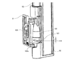
図14は、図13の回転軸66における縦断面図である。図15は、実施の形態1に係る冷蔵庫100の冷蔵室左扉6が開状態での仕切板8の下側ヒンジ部材51周辺の拡大図である。図16は、実施の形態1に係る冷蔵庫100の冷蔵室左扉6が開閉中での仕切板8の下側ヒンジ部材51周辺の拡大図である。図17は、実施の形態1に係る冷蔵庫100の冷蔵室左扉6の閉状態での仕切板8の下側ヒンジ部材51周辺の拡大図である。なお、図15~図17および後述する図22において、下側ヒンジ部材51は、その固定面106が冷蔵室左扉6の内板87と対向するように、内板87へネジ46で固定されている。
図14に示すように、下側ヒンジ部材51の軸形状部82には、その径方向外側へ突出したピン107が設けられている。また、下側ヒンジ部材51の軸形状部82の内部には、バネ102が収納されている。そして、そのバネ102は、背面側樹脂部材53の下部に設けられた筒受け形状部83によって蓋がされている。そのため、仕切板8は、バネ102の反力により本体部8aが上方向に押し上げられる。そして、上側ヒンジ部材49の腕部77と背面側樹脂部材53との間のクリアランス80および下側ヒンジ部材51の腕部81と背面側樹脂部材53との間のクリアランス84が狭くなり、その分だけ本体部8aの上端面つまり仕切板8の上端面72は上方向に移動する。
また、仕切板8が回転することで回転軸66方向に上下移動できるように、筒受け形状部83には、ピン107が納まる案内溝108が螺旋状に形成されている。なお、案内溝108は厳密に螺旋状に形成されていなくてもよい。案内溝108は、図15~図17に示すように、第一溝108a、第二溝108b、および、第三溝108cで構成されている。そして、第一溝108aは、冷蔵室左扉6が開状態でピン107が納まる位置、第二溝108bは、冷蔵室左扉6が閉状態でピン107が納まる位置にそれぞれ形成されている。また、第一溝108aは第二溝108bよりも高い位置に形成されている。そのため、鉛直方向あるいは縦方向における第一溝108aの上端と第一溝108aの上端との間には、第一溝108aと第二溝108bとの高さの差であるストローク114が形成されている。また、第一溝108aと第二溝108bとの間には、第三溝108cが傾斜して形成されており、第三溝108cで第一溝108aと第二溝108bとを繋げている。この第三溝108cは、第一溝108aと第二溝108bとを水平方向あるいは横方向にずらした分だけ長くなる。以上より、案内溝108は、縦方向かつ横方向にずらして形成された2つの溝である第一溝108aおよび第二溝108bと、それら2つの溝を繋ぐ傾斜溝である第三溝108cとで構成されている。
図15では、冷蔵室左扉6が開状態であり、ピン107は案内溝108内で最も高い位置に形成された第一溝108aに納まる位置にある。図16では、冷蔵室左扉6が閉じる途中の状態であり、ピン107は第一溝108aよりも低く、第二溝108bよりも高い位置に形成された第三溝108cに納まる位置にある。図17では、冷蔵室左扉6が閉状態であり、ピン107は案内溝108内で最も低い位置に形成された第二溝108bに納まる位置にある。
図18は、実施の形態1に係る冷蔵庫100の冷蔵室左扉6が閉じている状態を示す仕切板8の上側カバー部材48周辺の拡大図である。図19は、図18に示す冷蔵庫100の上部の横断面を下方から見た図である。図20は、図19よりも冷蔵室左扉6がさらに閉じている状態の図である。図21は、図20よりも冷蔵室左扉6がさらに閉じている状態の図である。なお、図21は、冷蔵室左扉6が完全に閉じた状態を示している。
図18に示すように、冷蔵室1の天井69の前方下部の中央には、冷蔵室左扉6の開閉時に仕切板8の本体部8aの回動をガイドするガイド部材71が取り付けられており、ガイド部材71には、下方に突出したガイド突起110が設けられている。このガイド突起110は、冷蔵室左扉6の開閉に連動し、冷蔵室左扉6が開閉した際に、上側カバー部材48に形成されたガイド突起案内凹部109に当接しながら冷蔵室左扉6の内板87に沿うように仕切板8の本体部8aを回動させるようになっている。
次に、冷蔵室左扉6の開閉に合わせて仕切板8がどのように動くかについて説明する。冷蔵室左扉6を開状態から閉じていくと、図19に示すように、上側カバー部材48に形成されたガイド突起案内凹部109に、ガイド部材71のガイド突起110が当接する。さらに冷蔵室左扉6を閉じていくと、図20に示すように、ガイド突起110に案内されて、冷蔵室左扉6と冷蔵室右扉7との間を塞ぐ方向に仕切板8の本体部8aは回動していく。このとき、ピン107に対して筒受け形状部83が動き、ピン107の位置は、相対的に案内溝108内で第一溝108a、第三溝108c、第二溝108bの順、つまり低い溝の方向に移動していく。そして、冷蔵室左扉6が完全に閉じると、図21に示すように、ピン107は第二溝108bに納まる位置となる。このとき、第一溝108aと第二溝108bとでは、第二溝108bの方が低い位置にある。そして、仕切板8の本体部8aが上方向に押し上げられるため、冷蔵室左扉6が開状態から閉状態になる際に、仕切板8の本体部8aは上方向に移動し、仕切板8の上端面72と冷蔵室1の天井69に設けられたガイド部材71の平らな下面73とが当接するようになっている(後述する図23参照)。なお、冷蔵室左扉6が閉状態から開状態になる際は、この逆の動作をすることになる。
図22は、図17のC部分の拡大図である。なお、図22は、仕切板8の下側ヒンジ部材51の内部構造が分かるように一部の部品を破線で示している。
次に、下側ヒンジ部材51の軸形状部82の内部に収納されているバネ102の必要性について説明する。経年劣化あるいは冷蔵室左扉6に取り付けられているポケット26に食品などが収納されるなどにより冷蔵室左扉6の位置が下がり、それによって仕切板8の上端面72の位置は、冷蔵室1の天井69に対して下がる。そのため、仕切板8の上端面72と冷蔵室1の天井69に設けられたガイド部材71の平らな下面73との間に上部隙間が形成されてしまう。そこで、仕切板8の本体部8aの位置をバネ102で変化させ、仕切板8の本体部8aを上方向に移動できるようにしている。そうすることで、仕切板8の上端面72と冷蔵室1の天井69に設けられたガイド部材71の平らな下面73とが当接し、上部隙間が形成されなくなる。
次に、下側ヒンジ部材51の軸形状部82の内部に収納されているバネ102の必要性について説明する。経年劣化あるいは冷蔵室左扉6に取り付けられているポケット26に食品などが収納されるなどにより冷蔵室左扉6の位置が下がり、それによって仕切板8の上端面72の位置は、冷蔵室1の天井69に対して下がる。そのため、仕切板8の上端面72と冷蔵室1の天井69に設けられたガイド部材71の平らな下面73との間に上部隙間が形成されてしまう。そこで、仕切板8の本体部8aの位置をバネ102で変化させ、仕切板8の本体部8aを上方向に移動できるようにしている。そうすることで、仕切板8の上端面72と冷蔵室1の天井69に設けられたガイド部材71の平らな下面73とが当接し、上部隙間が形成されなくなる。
実施の形態1では、仕切板8の背面側樹脂部材53の下部に設けられた筒受け形状部83に案内溝108が形成されており、ピン107が第一溝108aから第三溝108cの途中の間にある場合、ピン107は案内溝108の下端に位置する。また、ピン107が第三溝108cの途中を越えると、ピン107は案内溝108の下端から離れる。そして、ピン107が第二溝108bにある場合、ピン107は案内溝108の下端から若干のストローク111を有するところに位置する。これは、仕切板8の上端面72が冷蔵室1の天井69に設けられたガイド部材71の平らな下面73に当接し、その分バネ102を収縮させているためである。ここで、ストローク111は、ピン107の下端と第二溝108bの下端との間の隙間である。
そして、冷蔵室左扉6の閉時に冷蔵室左扉6の位置が下がったとしても、バネ102が伸張することで、このストローク111分、仕切板8を冷蔵室1の天井69に設けられたガイド部材71の平らな下面73へ追従させて当接させることができる。また、仕切板8の取り付け位置のばらつき、あるいは仕切板8の全長寸法のばらつきも、このストローク111により吸収できる。そのため、製品ばらつきによらず、仕切板8の上端面72と冷蔵室1の天井69に設けられたガイド部材71の平らな下面73とを安定的に当接させることができる。このストローク111は1mm程度であり、第一溝108aと第二溝108bとの高さの差、つまりストローク114(図16参照)よりも小さくする。そうすることで、冷蔵室左扉6の開閉による仕切板8の本体部8aの回動時に、冷蔵庫100の筐体101への衝突を抑制することができる。さらに、冷蔵室左扉6の開閉時に仕切板8の上端面72を冷蔵室1の天井69に設けられたガイド部材71の平らな下面73に当接させることができる。
ここで、アルミ箔ヒータ43への通電に関して、制御装置29には、あらかじめ試験などにより決定された通電率演算式がプログラミングされている。ここで、通電率とは、アルミ箔ヒータ43に印加する電圧を時間的に変化させたもので、例えば所定時間10秒のうちに5秒通電し、残り5秒は通電させないという形で定義されるものであり、この場合の通電率は50%である。アルミ箔ヒータ43への通電率は、外気温度、外気湿度、および、冷蔵室温度に応じて制御装置29によって演算されるものであり、周囲の環境に応じて変化していくものである。
制御装置29にプログラミングされている通電率演算式は、一例としては、通電率=a×外気湿度+bである。ここで、aおよびbは、A=外気温度-冷蔵室温度の値によって決定される係数であり、Aに値によって変化する。そして、制御装置29は、外気温度センサ9、外気湿度センサ10、および、冷蔵室温度センサ32で検知された外気温度、外気湿度、および、冷蔵室温度に応じて通電率演算式を演算することで、アルミ箔ヒータ43への通電率を決定する。この決定された通電率は、仕切板8の表面、冷蔵室左扉6および冷蔵室右扉7の周囲あるいはガスケット62、64およびガスケットヒレ63、65、75、76などに露が付かない通電率、つまりそれらの露付き耐力を向上させて結露を防止する通電率である。
ここで、通電率演算式から演算される通電率は、外気温度および外気湿度が高いほど通電率が大きくなり、冷蔵室1の温度が低いほど通電率が大きくなるようになっている。そして、制御装置29は、演算により決定した通電率で、アルミ箔ヒータ43を通電する。そのため、外気温度および外気湿度が低く、冷蔵室温度が高ければ通電率を小さくすることができるため、エネルギー効率を高めることができる。
図23は、図1のD-D断面矢視図である。図24は、従来の冷蔵庫の図23と同じ位置の断面矢視図である。
従来では、図24に示すように、冷蔵室左扉6の閉時にガスケットヒレ63、65が塞ぐ上部隙間67には断熱材45などは設けられていないため、ガスケットヒレ63、65の温度は上部隙間67の温度によって決まる。
そこで、実施の形態では、図23に示すように、冷蔵室左扉6が閉じた状態では、バネ102の反力112により仕切板8の上端面72が冷蔵室1の天井69に設けられたガイド部材71の平らな下面73に当接するようになっている。そして、仕切板8の上端面72が冷蔵室1の天井69に設けられたガイド部材71の平らな下面73に当接することにより、上部隙間67がなくなる。そのため、ガスケットヒレ63、65の裏面に冷気が直接当たらないようにすることができ、ガスケットヒレ63、65の表面温度を上昇させることができるので、必要以上に高くしている通電率を下げることができ、エネルギー効率を高めることができる。
なお、仕切板8の構成、アルミ箔ヒータ43への通電方法、および、通電率演算式などは、上記の内容に限定されない。例えば、仕切板8は、表面枠型樹脂部材44がない構成とすることも可能である。
図25は、実施の形態1に係る冷蔵庫100の変形例による上側ヒンジ部材49の周辺を拡大した斜視図である。なお、図25は、仕切板8の上側ヒンジ部材49の内部構造が分かるように一部の部品を破線で示している。
また、実施の形態1では、仕切板8の下部に、仕切板8の本体部8aの回動に合わせて仕切板8の本体部8aを上下方向の位置を変更させる機構、つまり、バネ102、ピン107、および、案内溝108を有する機構を設けたが、それに限定されない。仕切板8の下部に加えて、あるいは仕切板8の下部に代えて、図25に示すように仕切板8の上部にバネ102、ピン107、および、案内溝108を有する機構を設けてもよく、そうすることによっても同様の効果が得られる。
以上、実施の形態1に係る冷蔵庫100は、外郭を構成し、内部に冷蔵室1が設けられた筐体101と、筐体101の前面に設けられ、冷蔵室1の前面開口部を開閉する左右の観音開き式扉と、左右の観音開き式扉のうちの一方に回動可能に取り付けられて冷蔵室1内に外気が侵入するのを防ぐ仕切板8と、冷蔵室1の天井69の前方下部に設けられたガイド部材71と、を備えている。また、仕切板8は、上下に設けられ、観音開き式扉の内面に固定される上側ヒンジ部材49および下側ヒンジ部材51と、上側ヒンジ部材49および下側ヒンジ部材51に支持され、仕切板8が取り付けられた観音開き式扉の開閉時にガイド部材71にガイドされて回動する本体部8aと、を備えている。そして、仕切板8が取り付けられた観音開き式扉が閉じられた状態では、該観音開き式扉の開いている状態に比べて、本体部8aが上方向に移動しており、本体部8aの上端面72がガイド部材71の下面73と当接しているものである。
実施の形態1に係る冷蔵庫100によれば、仕切板8が取り付けられた観音開き式扉が閉じられた状態では、該観音開き式扉の開いている状態に比べて、本体部8aが上方向に移動しており、本体部8aの上端面72がガイド部材71の下面73と当接しているそのため、観音開き式扉が閉じられた状態において、仕切板8の上端面72と冷蔵室1の上側の前面開口部との間の隙間を減らすことができる。また、ボールキャスタおよびガイドレールは不要であるため、使い勝手の低下を抑制することができる。また、仕切板8の上端面72にパッキンなども不要となり、仕切板8の動作性の低下も抑制することができる。さらには、仕切板8の上端面72とガイド部材71の下面73との間を塞ぐことができるので、その隙間を防いでガスケットヒレ63、65の裏面に冷気が直接当たらないようにすることができ、ガスケットヒレ63、65の表面温度を上昇させることができる。そのため、必要以上に高くしている通電率を下げることができ、エネルギー効率を高めることができる。
また、実施の形態1に係る冷蔵庫100において、軸形状部82の内部には、バネ102が収納されており、バネ102は、筒受け形状部83によって蓋がされている。そして、仕切板8が取り付けられた観音開き式扉を閉じる際に、軸形状部82を中心に回動するにつれて、ピン107が案内溝108内で低い方に移動し、バネ102の反力により本体部8aの上端面72が上方向に移動する。
実施の形態1に係る冷蔵庫100によれば、製品ばらつきによらず、仕切板8の上端面72と冷蔵室1の天井69に設けられたガイド部材71の平らな下面73とを安定的に当接させることができる。
実施の形態2.
以下、実施の形態2について説明するが、実施の形態1と重複するものについては説明を省略し、実施の形態1と同じ部分または相当する部分には同じ符号を付す。
以下、実施の形態2について説明するが、実施の形態1と重複するものについては説明を省略し、実施の形態1と同じ部分または相当する部分には同じ符号を付す。
図26は、実施の形態2に係る冷蔵庫100の縦断面図である。なお、図26は、実施の形態1の図23と同じ位置の断面矢視図である
実施の形態2では、実施の形態1とは異なり、下側ヒンジ部材51の軸形状部82にピン107が設けられておらず、背面側樹脂部材53の下部に設けられた筒受け形状部83に案内溝108が形成されていない。
実施の形態2では、図26に示すようにガイド部材71の内部に磁石113が設けられている。また、上側カバー部材48を固定するネジ46が仕切板8の上端面72に配置されている。そして、仕切板8の上端面72に配置されているネジ46をガイド部材71の内部に設けられている磁石113の磁力により引きつけ、仕切板8の本体部8aを上方向に移動させる。そうすることで、冷蔵室左扉6の閉時に仕切板8の上端面72と冷蔵室1の天井69に設けられたガイド部材71の平らな下面73とを当接させる。
ここで、図12および図13に示す、上側ヒンジ部材49および下側ヒンジ部材51の腕部77、81と背面側樹脂部材53との間のクリアランス80、84を、遊び寸法とする。冷蔵室左扉6の開時には、仕切板8の背面側樹脂部材53は重力により下方向に移動し、仕切板8の背面側樹脂部材53の下部に設けられた筒受け形状部83の下端面が、下側ヒンジ部材51の腕部81に乗っている状態となる。一方、冷蔵室左扉6の閉時には、仕切板8の上端面72のネジ46がガイド部材71の内部の磁石113の磁力により引きつけられ、仕切板8の本体部8aが上方向に移動するようになっている。このとき、図24に示す、従来の冷蔵庫100の仕切板8の上端面72と冷蔵室1の天井69に設けられたガイド部材71の平らな下面73との間の上部隙間67は、遊び寸法よりも小さいものとする。このようにしているのは、上部隙間67が遊び寸法よりも大きいと、冷蔵室左扉6の閉時に仕切板8の上端面72が冷蔵室1の天井69に設けられたガイド部材71の平らな下面73に当接しないためである。
図27は、実施の形態2に係る冷蔵庫100の変形例による仕切板8の上部を拡大した斜視図である。
なお、仕切板8の上端面72にネジ46ではなく、図27に示すように表面板金42の上端部に折り曲げ部42aを形成し、その折り曲げ部42aを仕切板8の上端面72に固定する。そして、表面板金42の折り曲げ部42aがガイド部材71の内部の磁石113の磁力により引きつけられるようにしてもよい。なお、表面板金42の折り曲げ部42aは、表面板金42の上端部が、仕切板8の上端面72の表面側からある程度、ガイド突起110により回動する上側カバー部材48のガイド突起案内凹部109の手前くらいまで折り曲げられることで、形成される。
なお、仕切板8の上端面72にネジ46ではなく、図27に示すように表面板金42の上端部に折り曲げ部42aを形成し、その折り曲げ部42aを仕切板8の上端面72に固定する。そして、表面板金42の折り曲げ部42aがガイド部材71の内部の磁石113の磁力により引きつけられるようにしてもよい。なお、表面板金42の折り曲げ部42aは、表面板金42の上端部が、仕切板8の上端面72の表面側からある程度、ガイド突起110により回動する上側カバー部材48のガイド突起案内凹部109の手前くらいまで折り曲げられることで、形成される。
実施の形態2においても、冷蔵室左扉6の開閉に合わせて仕切板8の本体部8aが回動するようになっており、冷蔵室左扉6の閉時には仕切板8の上端面72が冷蔵室1の天井69に設けられたガイド部材71の平らな下面73に当接して上部隙間67がなくなる。そのため、ガスケットヒレ63、65の裏面に冷気が直接当たらないようにすることができ、ガスケットヒレ63、65の表面温度を上昇させることができるので、必要以上に高くしている通電率を下げることができ、エネルギー効率を高めることができる。
以上、実施の形態2に係る冷蔵庫100において、本体部8aの上端面72にネジ46が配置されており、ガイド部材71の内部に磁石113が設けられている。そして、仕切板8が取り付けられた観音開き式扉が閉じられた状態では、該観音開き式扉の開いている状態に比べて、ネジ46が磁石113に引きつけられており、本体部8aの上端面72がガイド部材71の下面73と当接している。
また、実施の形態2に係る冷蔵庫100において、本体部8aは、表面側に位置する金属製の表面板金42を有し、表面板金42は、上端部が折り曲げられた折り曲げ部42aを有し、本体部8aの上端面72には、表面板金42の折り曲げ部42aが配置されており、ガイド部材71の内部に磁石113が設けられている。そして、仕切板8が取り付けられた観音開き式扉が閉じられた状態では、該観音開き式扉の開いている状態に比べて、折り曲げ部42aが磁石113に引きつけられており、本体部8aの上端面72がガイド部材71の下面73と当接している。
実施の形態2に係る冷蔵庫100によれば、仕切板8が取り付けられた観音開き式扉が閉じられた状態では、該観音開き式扉の開いている状態に比べて、ネジ46が磁石113に引きつけられており、本体部8aの上端面72がガイド部材71の下面73と当接している。または、仕切板8が取り付けられた観音開き式扉が閉じられた状態では、該観音開き式扉の開いている状態に比べて、折り曲げ部42aが磁石113に引きつけられており、本体部8aの上端面72がガイド部材71の下面73と当接している。そのため、観音開き式扉が閉じられた状態において、仕切板8の上端面72と冷蔵室1の上側の前面開口部との間の隙間を減らすことができる。また、ボールキャスタおよびガイドレールは不要であるため、使い勝手の低下を抑制することができる。また、仕切板8の上端面72にパッキンなども不要となり、仕切板8の動作性の低下も抑制することができる。さらには、仕切板8の上端面72とガイド部材71の下面73との間を塞ぐことができるので、その隙間を防いでガスケットヒレ63、65の裏面に冷気が直接当たらないようにすることができ、ガスケットヒレ63、65の表面温度を上昇させることができる。そのため、必要以上に高くしている通電率を下げることができ、エネルギー効率を高めることができる。
実施の形態3.
以下、実施の形態3について説明するが、実施の形態1と重複するものについては説明を省略し、実施の形態1と同じ部分または相当する部分には同じ符号を付す。
以下、実施の形態3について説明するが、実施の形態1と重複するものについては説明を省略し、実施の形態1と同じ部分または相当する部分には同じ符号を付す。
経年劣化あるいは冷蔵室左扉6に取り付けられているポケット26に食品などが収納されるなどしても、冷蔵室左扉6の位置が下がらない程度に、冷蔵室扉のヒンジ構造を強固にした場合、仕切板8の上端面72と冷蔵室1の天井69との距離が一定となる。そこで、冷蔵室扉のヒンジ構造を、冷蔵室左扉6の位置が下がらない程度に強固にすることで、バネ102の反力による押し上げ構造あるいは磁石113の磁力による引き込み構造が不要となり、コストを低減することができる。
実施の形態1では、ピン107と案内溝108とを備えた仕切板8において、図15~図17に示すように、案内溝108内をピン107が移動することで、冷蔵室左扉6の開閉に合わせて仕切板8の本体部8aが上下に移動する。これに対して実施の形態3では、実施の形態1で説明したバネ102および実施の形態2で説明した磁石113などの、仕切板8の一部の上下移動を補助する部材(以下、上下移動補助部材と称する)を備えていない。そのため、冷蔵室左扉6の開時に、仕切板8の本体部8aは、自重によりピン107と案内溝108とが接しながら回動する。
図16に示すストローク114を調整することで、冷蔵室左扉6の閉時には仕切板8の上端面72が冷蔵室1の天井69に設けられたガイド部材71の平らな下面73に当接して上部隙間67がなくなる。そのため、ガスケットヒレ63、65の裏面に冷気が直接当たらないようにすることができ、ガスケットヒレ63、65の表面温度を上昇させることができるので、必要以上に高くしている通電率を下げることができ、エネルギー効率を高めることができる。
なお、実施の形態3では、仕切板8の下部に、仕切板8の本体部8aの回動に合わせて仕切板8の本体部8aを上下方向の位置を変更させる機構、つまり、ピン107および案内溝108を有する機構(ただし、上下移動補助部材なし)を設けたが、それに限定されない。仕切板8の下部に加えて、あるいは仕切板8の下部に代えて、仕切板8の上部にピン107および案内溝108を有する機構を設けてもよく、そうすることによっても同様の効果が得られる。
1 冷蔵室、2 製氷室、3 小型冷凍室、4 冷凍室、5 野菜室、6 冷蔵室左扉、7 冷蔵室右扉、8 仕切板、8a 本体部、9 外気温度センサ、10 外気湿度センサ、11 ヒンジカバー部材、12 圧縮機、13 機械室凝縮器、14 左側側面凝縮配管、15 天井面凝縮配管、16 背面凝縮配管、17 右側側面凝縮配管、18 露付き防止配管、19 ドライヤ、20 毛細管、21 冷却器、23 吸入配管、26 ポケット、27 チルド室、28 チルドケース、29 制御装置、30 棚、31 冷蔵室用ダンパー装置、32 冷蔵室温度センサ、33~41 矢印、42 表面板金、42a 折り曲げ部、43 アルミ箔ヒータ、44 表面枠型樹脂部材、45 断熱材、46 ネジ、47 バネ止め、48 上側カバー部材、49 上側ヒンジ部材、50 下側カバー部材、51 下側ヒンジ部材、52 バネ、53 背面側樹脂部材、54 アルミ箔、55 両面テープ、56 コード状ヒータ、57 ツメ受け部、58 芯材、59 発熱線、60 絶縁被覆材、61 絶縁被覆材、62 ガスケット、63 ガスケットヒレ、64 ガスケット、65 ガスケットヒレ、66 回転軸、67 上部隙間、68 ツメ、69 天井、70 前面フランジ部、71 ガイド部材、72 上端面、73 下面、75 ガスケットヒレ、76 ガスケットヒレ、77 腕部、78 軸形状部、79 筒受け形状部、80 クリアランス、81 腕部、82 軸形状部、83 筒受け形状部、84 クリアランス、85 バッフル、86 冷蔵室吹出し風路、87 内板、88 内板、96 キャップ部品、97 キャップ部品、98 扉表面パネル、99 扉表面パネル、100 冷蔵庫、101 筐体、102 バネ、103 設定操作部、104 冷媒回路、106 固定面、107 ピン、108 案内溝、108a 第一溝、108b 第二溝、108c 第三溝、109 ガイド突起案内凹部、110 ガイド突起、111 ストローク、112 反力、113 磁石、114 ストローク。
Claims (6)
- 外郭を構成し、内部に冷蔵室が設けられた筐体と、
前記筐体の前面に設けられ、前記冷蔵室の前面開口部を開閉する左右の観音開き式扉と、
左右の前記観音開き式扉のうちの一方に回動可能に取り付けられて前記冷蔵室内に外気が侵入するのを防ぐ仕切板と、
前記冷蔵室の天井の前方下部に設けられたガイド部材と、を備え、
前記仕切板は、
上下に設けられ、前記観音開き式扉の内面に固定される上側ヒンジ部材および下側ヒンジ部材と、
前記上側ヒンジ部材および前記下側ヒンジ部材に支持され、前記仕切板が取り付けられた前記観音開き式扉の開閉時に前記ガイド部材にガイドされて回動する本体部と、を備え、
前記仕切板が取り付けられた前記観音開き式扉が閉じられた状態では、該観音開き式扉の開いている状態に比べて、前記本体部が上方向に移動しており、前記本体部の上端面が前記ガイド部材の下面と当接している
冷蔵庫。 - 前記本体部は、下部に筒状の筒受け形状部を有し、
前記下側ヒンジ部材は、径方向外側へ突出したピンと、前記筒受け形状部と嵌合する筒状の軸形状部とを有し、
前記筒受け形状部には、前記ピンが納まる案内溝が形成されており、
前記案内溝は、縦方向かつ横方向にずらして形成された2つの溝と、2つの該溝を繋ぐ傾斜溝とで構成されており、
前記仕切板が取り付けられた前記観音開き式扉を閉じる際に、
前記軸形状部を中心に前記本体部が回動するにつれて、前記ピンが前記案内溝内で低い方に移動して前記本体部の前記上端面が上方向に移動する
請求項1に記載の冷蔵庫。 - 前記本体部は、上部に筒状の筒受け形状部を有し、
前記上側ヒンジ部材は、径方向外側へ突出したピンと、前記筒受け形状部と嵌合する筒状の軸形状部とを有し、
前記筒受け形状部には、前記ピンが納まる案内溝が形成されており、
前記案内溝は、縦方向かつ横方向にずらして形成された2つの溝と、2つの該溝を繋ぐ傾斜溝とで構成されており、
前記仕切板が取り付けられた前記観音開き式扉を閉じる際に、
前記軸形状部を中心に前記本体部が回動するにつれて、前記ピンが前記案内溝内で低い方に移動して前記本体部の前記上端面が上方向に移動する
請求項1に記載の冷蔵庫。 - 前記軸形状部の内部には、バネが収納されており、
前記バネは、前記筒受け形状部によって蓋がされており、
前記仕切板が取り付けられた前記観音開き式扉を閉じる際に、
前記軸形状部を中心に回動するにつれて、前記ピンが前記案内溝内で低い方に移動し、前記バネの反力により前記本体部の前記上端面が上方向に移動する
請求項2または3に記載の冷蔵庫。 - 前記本体部の前記上端面にネジが配置されており、
前記ガイド部材の内部に磁石が設けられており、
前記仕切板が取り付けられた前記観音開き式扉が閉じられた状態では、該観音開き式扉の開いている状態に比べて、前記ネジが前記磁石に引きつけられており、前記本体部の前記上端面が前記ガイド部材の前記下面と当接している
請求項1に記載の冷蔵庫。 - 前記本体部は、表面側に位置する金属製の表面板金を有し、
前記表面板金は、上端部が折り曲げられた折り曲げ部を有し、
前記本体部の前記上端面には、前記表面板金の前記折り曲げ部が配置されており、
前記ガイド部材の内部に磁石が設けられており、
前記仕切板が取り付けられた前記観音開き式扉が閉じられた状態では、該観音開き式扉の開いている状態に比べて、前記折り曲げ部が前記磁石に引きつけられており、前記本体部の前記上端面が前記ガイド部材の前記下面と当接している
請求項1に記載の冷蔵庫。
Priority Applications (2)
| Application Number | Priority Date | Filing Date | Title |
|---|---|---|---|
| JP2022507117A JP7275378B2 (ja) | 2020-03-12 | 2020-03-12 | 冷蔵庫 |
| PCT/JP2020/010838 WO2021181609A1 (ja) | 2020-03-12 | 2020-03-12 | 冷蔵庫 |
Applications Claiming Priority (1)
| Application Number | Priority Date | Filing Date | Title |
|---|---|---|---|
| PCT/JP2020/010838 WO2021181609A1 (ja) | 2020-03-12 | 2020-03-12 | 冷蔵庫 |
Publications (1)
| Publication Number | Publication Date |
|---|---|
| WO2021181609A1 true WO2021181609A1 (ja) | 2021-09-16 |
Family
ID=77670553
Family Applications (1)
| Application Number | Title | Priority Date | Filing Date |
|---|---|---|---|
| PCT/JP2020/010838 Ceased WO2021181609A1 (ja) | 2020-03-12 | 2020-03-12 | 冷蔵庫 |
Country Status (2)
| Country | Link |
|---|---|
| JP (1) | JP7275378B2 (ja) |
| WO (1) | WO2021181609A1 (ja) |
Citations (6)
| Publication number | Priority date | Publication date | Assignee | Title |
|---|---|---|---|---|
| JP2000161841A (ja) * | 1998-11-30 | 2000-06-16 | Mitsubishi Electric Corp | 冷蔵庫 |
| US20140159560A1 (en) * | 2012-12-10 | 2014-06-12 | Lg Electronics Inc. | Refrigerator |
| KR20150003642A (ko) * | 2013-07-01 | 2015-01-09 | 주식회사 대유위니아 | 양문형 냉장고의 실링장치 |
| JP2018112385A (ja) * | 2017-01-06 | 2018-07-19 | パナソニック株式会社 | 冷蔵庫 |
| WO2020012629A1 (ja) * | 2018-07-13 | 2020-01-16 | 三菱電機株式会社 | 冷蔵庫 |
| WO2020012526A1 (ja) * | 2018-07-09 | 2020-01-16 | 三菱電機株式会社 | 冷蔵庫 |
-
2020
- 2020-03-12 JP JP2022507117A patent/JP7275378B2/ja active Active
- 2020-03-12 WO PCT/JP2020/010838 patent/WO2021181609A1/ja not_active Ceased
Patent Citations (6)
| Publication number | Priority date | Publication date | Assignee | Title |
|---|---|---|---|---|
| JP2000161841A (ja) * | 1998-11-30 | 2000-06-16 | Mitsubishi Electric Corp | 冷蔵庫 |
| US20140159560A1 (en) * | 2012-12-10 | 2014-06-12 | Lg Electronics Inc. | Refrigerator |
| KR20150003642A (ko) * | 2013-07-01 | 2015-01-09 | 주식회사 대유위니아 | 양문형 냉장고의 실링장치 |
| JP2018112385A (ja) * | 2017-01-06 | 2018-07-19 | パナソニック株式会社 | 冷蔵庫 |
| WO2020012526A1 (ja) * | 2018-07-09 | 2020-01-16 | 三菱電機株式会社 | 冷蔵庫 |
| WO2020012629A1 (ja) * | 2018-07-13 | 2020-01-16 | 三菱電機株式会社 | 冷蔵庫 |
Also Published As
| Publication number | Publication date |
|---|---|
| JP7275378B2 (ja) | 2023-05-17 |
| JPWO2021181609A1 (ja) | 2021-09-16 |
Similar Documents
| Publication | Publication Date | Title |
|---|---|---|
| US20120047922A1 (en) | Direct cooling refrigerator and control method thereof | |
| AU2022200857B2 (en) | Refrigerator | |
| CN102679663A (zh) | 冰箱 | |
| WO2006049355A9 (en) | Defrost operating method for refrigerator | |
| US11022329B1 (en) | Humidity control system | |
| US11549741B2 (en) | Apparatus for sensing and removing dew on refrigerator and controlling method thereof | |
| JP2017146094A (ja) | 遮蔽装置およびそれを有する冷蔵庫 | |
| KR20160001389A (ko) | 냉장고 및 그 제어 방법 | |
| JP2013224777A (ja) | 冷蔵庫 | |
| JP7275378B2 (ja) | 冷蔵庫 | |
| JP7066058B2 (ja) | 冷蔵庫 | |
| JP7389615B2 (ja) | 冷蔵庫 | |
| JP6214486B2 (ja) | 冷蔵庫 | |
| CN219328234U (zh) | 冰箱 | |
| WO2020250421A1 (ja) | 冷蔵庫 | |
| JP2016161231A (ja) | 冷蔵庫 | |
| JP6987297B2 (ja) | 冷蔵庫 | |
| JP6956900B2 (ja) | 冷蔵庫 | |
| JP6694538B2 (ja) | 冷蔵庫 | |
| JP7275377B2 (ja) | 冷蔵庫 | |
| CN223106351U (zh) | 存储设备 | |
| HK40064783A (en) | Refrigerator | |
| JP7312148B2 (ja) | 冷蔵庫 | |
| CN1888778B (zh) | 泡菜冰箱的内部机壳增强结构 | |
| HK40064783B (en) | Refrigerator |
Legal Events
| Date | Code | Title | Description |
|---|---|---|---|
| 121 | Ep: the epo has been informed by wipo that ep was designated in this application |
Ref document number: 20924248 Country of ref document: EP Kind code of ref document: A1 |
|
| ENP | Entry into the national phase |
Ref document number: 2022507117 Country of ref document: JP Kind code of ref document: A |
|
| NENP | Non-entry into the national phase |
Ref country code: DE |
|
| 122 | Ep: pct application non-entry in european phase |
Ref document number: 20924248 Country of ref document: EP Kind code of ref document: A1 |