WO2021181475A1 - 輸液バッグ加圧容器、輸液バッグ加圧装置 - Google Patents
輸液バッグ加圧容器、輸液バッグ加圧装置 Download PDFInfo
- Publication number
- WO2021181475A1 WO2021181475A1 PCT/JP2020/010087 JP2020010087W WO2021181475A1 WO 2021181475 A1 WO2021181475 A1 WO 2021181475A1 JP 2020010087 W JP2020010087 W JP 2020010087W WO 2021181475 A1 WO2021181475 A1 WO 2021181475A1
- Authority
- WO
- WIPO (PCT)
- Prior art keywords
- pressure
- infusion bag
- bag
- pressurizing
- contact
- Prior art date
- Legal status (The legal status is an assumption and is not a legal conclusion. Google has not performed a legal analysis and makes no representation as to the accuracy of the status listed.)
- Ceased
Links
Images




Classifications
-
- A—HUMAN NECESSITIES
- A61—MEDICAL OR VETERINARY SCIENCE; HYGIENE
- A61M—DEVICES FOR INTRODUCING MEDIA INTO, OR ONTO, THE BODY; DEVICES FOR TRANSDUCING BODY MEDIA OR FOR TAKING MEDIA FROM THE BODY; DEVICES FOR PRODUCING OR ENDING SLEEP OR STUPOR
- A61M5/00—Devices for bringing media into the body in a subcutaneous, intra-vascular or intramuscular way; Accessories therefor, e.g. filling or cleaning devices, arm-rests
- A61M5/14—Infusion devices, e.g. infusing by gravity; Blood infusion; Accessories therefor
- A61M5/142—Pressure infusion, e.g. using pumps
- A61M5/145—Pressure infusion, e.g. using pumps using pressurised reservoirs, e.g. pressurised by means of pistons
- A61M5/148—Pressure infusion, e.g. using pumps using pressurised reservoirs, e.g. pressurised by means of pistons flexible, e.g. independent bags
Definitions
- the present invention relates to a medical device, and particularly relates to an infusion bag pressurizing container and an infusion bag pressurizing device for performing infusion by pressurization.
- infusion devices such as hanging on an infusion stand, an infusion syringe pump, and an electrically driven pressurized infusion bag are known as medical devices for infusion.
- the flow rate is relatively stable, but there are restrictions on the installation location, and it is necessary to carry the stand when moving, and it is difficult to go out because there is a risk of falling.
- an infusion syringe pump the flow rate fluctuation is small and the performance is high, but a power source and an emergency battery are required, and the equipment is large and not suitable for movement.
- an infusion bag pressurizing device see Patent Document 1 that does not need to be hung by pressurizing the infusion bag with air pressure or the like.
- a liquid supply device see Patent Documents 2 and 3 previously filed by the present applicant.
- Japanese Unexamined Patent Publication No. 2004-230032 (Nippon TMI Co., Ltd.) International Publication No. 2017/134737 (Irie Koken Co., Ltd., Green Apple Co., Ltd.) Japanese Patent No. 6298208 (Irie Koken Co., Ltd., Yoshiyuki Watanabe)
- Patent Document 1 the film surface tension strongly acts on the contact surface of the pressure mediation bag (denoted as “pressurized bag” in Patent Document 1) with respect to the infusion bag. It becomes. As a result, even if the pressure in the pressure mediation bag is constant, there is a problem that the pressure of the chemical solution in the infusion bag changes and the discharge flow rate changes.
- the present invention proposes a structure that solves this problem. First, the cause of this problem will be described.
- the pressure of the pressurized air in the pressure mediation bag is transmitted to the chemical solution in the infusion bag, and the chemical solution is pushed out to the outlet.
- the air pressure in the pressure mediation bag it is important to keep the air pressure in the pressure mediation bag constant and to keep the hydraulic pressure transmitted to the chemical solution constant.
- the membrane surface of the pressure mediation bag is also flat.
- the mechanism of pressure transmission in this case is considered as follows.
- the force due to the pressure of the air in the pressure mediation bag acts in the direction perpendicular to the facing flat membrane surface. Since the drug solution in the infusion bag is pushed but confined, the fluid pressure rises until it balances the force transmitted from the membrane surface.
- the water pressure related to the depth of the liquid does not need to be considered. In this case, even if the film surface tension acts on the film surface of the pressure mediation bag, the force due to the film surface tension does not act in the direction perpendicular to the film surface because the film surface is flat.
- the bag shape of the infusion bag will have a convex curved surface when the drug solution is filled.
- the film surface of the pressure mediation bag that closely presses the pressure mediation bag from the outside has a concave curved surface when viewed from the pressure mediation bag.
- the resultant force of tension acts in the direction of trying to flatten the curved surface of the film surface according to the radius of curvature. Therefore, the pressure of the chemical solution in the infusion bag increases until a force that balances the force due to the pressure of the air in the pressure mediation bag and the force due to the membrane surface tension is generated. become.
- the pressure of the chemical solution becomes higher than the pressure of the pressurized air. It can be said that this is similar to the phenomenon that the pressure inside the bubble becomes higher than the pressure of the surrounding liquid due to the action of surface tension.
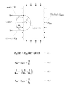
- FIG. 14 is a conceptual diagram used to explain that the pressure inside the bubble is increased by surface tension. If there are bubbles with radius R in the liquid and the pressure inside the bubbles is PIN and the pressure of the liquid is P OUT , the surface tension T works as shown in the figure, so the balance of forces is maintained and the liquid stands still. In order to be in the state, the pressure PIN in the bubble must be large.
- the equation for the equilibrium of force is Equation 1. When this is transformed into Equation 2, this equation is called Laplace's equation.
- Equation 3 representing the average radius of curvature R M obtained from the main radius of curvature R 1 and R 2 Generalizing this relationship if not spherical, can be expressed as Equation 4. In this phenomenon, the smaller the radius of curvature, the larger the pressure difference between the internal air pressure of the bubble and the ambient liquid pressure. Further, the pressure difference becomes larger as the combination of gas-liquid interfaces increases the surface tension.
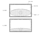
- the pressurizing bag In a state where there is an infusion bag filled with liquid and a bag that inflates to pressurize in a hard container as shown in FIG. 15, the pressurizing bag has a tension on the membrane surface and the infusion bag. Touch along the bulging surface of.
- the bag shape of the infusion bag is crushed when the chemical solution in the infusion bag is discharged.
- most of the chemicals are discharged from a state in which the radius of curvature is small and swollen, most of the film surface approaches a plane having a large radius of curvature. Therefore, when the membrane surface of the pressure mediation bag has a strong membrane surface tension, the pressure of the chemical solution becomes higher than the pressure of the pressurized air at the initial stage of the infusion solution. Then, as the discharge progresses, a phenomenon that gradually approaches the pressure of the pressurized air occurs. As a result, even if the pressure of the pressurized air is kept constant, a phenomenon occurs in which the pressure of the chemical solution decreases and the flow rate decreases in the later stage as compared with the initial stage of the infusion solution.
- Patent Document 1 a method of pressing the infusion bag containing a chemical solution while inflating the pressurizing bag with air is adopted as a pressurizing means, but the pressing surface of the pressurizing bag is adopted. Is a structure in which the film surface tension becomes strong, and it is clear that no technical measures have been taken to deal with the change in curvature and the transmitted pressure as the chemical solution is discharged.
- the pressure of the chemical solution in the infusion bag is brought close to the pressure of the pressurized air, and a constant discharge flow rate can be obtained during the infusion bag. It is an object of the present invention to provide a pressurizing container and an infusion bag pressurizing device.
- the invention according to claim 1 is an infusion bag pressurizing container for accommodating and pressurizing an infusion bag inside, and is connected to a pressurizing means for increasing a pressure transmitting fluid for pressurizing the infusion bag to be higher than atmospheric pressure.
- the infusion bag compression means which has a portion and presses the infusion bag with the pressure-pressed pressure transfer fluid, presses the contact film that contacts the infusion bag and transmits pressure, and the pressure transmission fluid that pushes the contact film.
- It is a pressure mediation container composed of an outer surface to be sealed, and is an infusion bag pressurizing container characterized by having a contact film surface tension reducing structure in which the tension of the film surface of the contact film is reduced.
- the infusion bag compression means is a pressure mediation bag having a shape in which the contact film wraps the infusion bag except for the discharge port of the infusion bag, and has a structure for reducing the surface tension of the contact film.
- a double pressure mediation bag having a double bag structure having an outer film that seals the contact film in a shape that encloses the layer of the pressure transmission fluid, and serves as an inner surface of the double pressure mediation bag.
- the infusion bag compression means is the double pressure mediation bag
- the contact membrane surface tension reducing structure is an inlet when the infusion bag is inserted into the double pressure mediation bag.
- the pressure is formed by connecting and closing the outer membranes of the opening so that the membrane surface tension can be transmitted to each other, except for the discharge port.
- an opening outer membrane connection type pressure mediation bag provided with an opening outer membrane connecting structure that allows the outer membrane to receive an expansion force due to the pressure of the transmission fluid, and is a cylinder of the contact membrane serving as the inner side surface.
- the infusion bag compression means is the double pressure mediation bag
- the contact membrane surface tension reducing structure includes a hard mediation bag container for accommodating the double pressure mediation bag. Further, at the opening on the inner side surface that serves as an inlet when the infusion bag is inserted into the double pressure mediation bag, after the infusion bag is inserted, the membrane surface of the opening is suppressed except for the discharge port. It is due to the double pressure mediating bag housed in a holding lid type mediating bag container having a structure, and is characterized in that the tension in the direction perpendicular to the tube circumference direction of the contact film serving as the inner side surface is reduced. , The infusion bag pressurizing container according to claim 2.
- the contact film surface tension reducing structure is formed of a hard surface in which the first contact surface in contact with one wide surface of the infusion bag is not deformed, and is formed on the other wide surface of the infusion bag.
- a structure in which the second contact surface in contact serves as the contact film has an outer surface that seals the contact film in a shape that encloses the layer of the pressure transmitting fluid, and the outer surface is connected to the hard first contact surface.
- the invention according to claim 6 comprises the infusion bag pressurizing container according to any one of claims 1 to 5, wherein the pressurizing means is a pressure transmitting fluid boosting piston connected to a vacuum piston. It is a characteristic infusion bag pressurizing device.
- the invention according to claim 7 comprises the infusion bag pressurizing container according to any one of claims 1 to 5, wherein the pressurizing means is a pressure transmitting fluid boosting bellows connected to a vacuum piston. It is a characteristic infusion bag pressurizing device.
- the invention according to claim 8 is characterized in that the pressurizing means includes an infusion bag pressurizing container according to any one of claims 1 to 5, which is an electric pressurizing pump. It is a pressure device.
- the invention according to claim 9 is characterized in that the pressurizing means includes an infusion bag pressurizing container according to any one of claims 1 to 5, which is a pressure accumulator cylinder and a constant pressure regulator. It is a pressurizing device.
- the invention according to claim 10 is the invention according to claim 6, wherein the boosting means is a pressure transmitting fluid boosting piston connected to a vacuum piston, and includes a constant pressure regulator for stabilizing the pressure. It is an infusion bag pressurizing device.
- the boosting means is a pressure transmitting fluid boosting piston connected to a vacuum piston, and includes a constant pressure regulator for stabilizing the pressure. It is an infusion bag pressurizing device.
- a pressure mediation bag structure capable of reducing a change in transmission pressure caused by a change in the shape of the infusion bag due to chemical discharge is adopted.
- the effect that the flow rate of the chemical liquid discharged by the infusion bag pressurizing device can be made constant can be obtained.
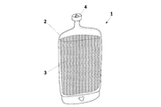
- FIG. 1 is an external view showing a state in which the infusion bag is housed in the infusion bag pressurizing container of FIG.
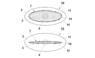
- FIG. 3 is a cross-sectional view showing a state in which the infusion bag is pressed by the infusion bag pressurizing container of FIG.
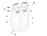
- FIG. 5 is a cross-sectional view showing a state in which the infusion bag is pressed by the infusion bag pressurizing container of FIG.
- the schematic diagram which shows the structure of the infusion bag pressurizing apparatus which applied the accumulator cylinder and the constant pressure regulator as a boosting means.
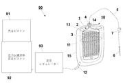
- the schematic diagram which shows the structure of the infusion bag pressurizing apparatus which is the pressure transmission fluid boosting piston connected to the vacuum piston as a boosting means, and which applied the constant pressure regulator which stabilizes a pressure.
- the cross-sectional view which shows the state when the infusion bag is pressed by the pressure bag with strong membrane surface tension.
- the infusion bag pressurizing container 10 of the first embodiment is a container for accommodating an infusion bag and pressurizing the inside when infusion is performed.
- the infusion bag 1 to be used has a liquid (chemical solution) 3 sealed inside the main body 2 and has a discharge port 4 for connecting a conduit tube described later, and is already commercially available. Can be used.
- the infusion bag pressurizing container 10 has a connection portion 12 with a pressurizing means that raises the pressure transmission fluid (air) 11 enclosed therein to be higher than the atmospheric pressure in order to pressurize the infusion bag 1.
- the pressure transfer fluid 10 is generally air, but may be a gas other than air or a liquid such as water or silicone oil.
- an envelope sleeping bag type pressure mediation container is adopted as an infusion bag compression means for pressing the infusion bag 1 with the pressurized air.
- the pressure mediation container is composed of an opening 13 into which the infusion bag 1 is inserted, a contact membrane 14 that contacts the infusion bag 1 to transmit pressure, and an outer membrane 15 that seals the air that pushes the contact membrane 14. It is a pressure mediation bag.
- the infusion bag 1 filled with the liquid 3 has a convex shape bulging outward, and when the membrane surface of the contact film 14 of the pressure mediation bag is in contact with the contact film 14 in a concave shape and tension is generated in the contact film 14. The resultant force of the tension of the membrane surface is applied to the infusion bag 1. Therefore, the pressure of the liquid 3 in the infusion bag 1 becomes higher than the pressure of the pressure transmission fluid 11 in the pressure mediation bag. Further, when the main body 2 is deformed into a flat shape due to the discharge of the liquid 3 in the infusion bag 1, the radius of curvature of the concave surface of the contact film 14 becomes large and the resultant force of the film surface tension becomes small. The pressure of the liquid 3 in 1 becomes smaller so as to approach the pressure of the air 11 in the pressure mediation bag. As a result, with the conventional method, the flow rate is lower at the final stage of discharge than at the initial stage of discharge of the infusion solution.
- the infusion bag pressurizing container 10 of the present embodiment is characterized by having a contact membrane surface tension reducing structure capable of reducing the membrane surface tension of the contact membrane 14 of the pressure mediation bag.
- the contact membrane 14 is a pressure mediation bag having a shape that wraps the infusion bag 1 except for the portion of the discharge port 4 of the infusion bag 1, and the contact membrane 14 is sealed in a shape that wraps the air layer.
- It can be a double pressure mediation bag having a double bag structure having an outer membrane 15.
- the pressure mediation bag has a contact film surface tension reduction structure in which the tension in the tubular circumferential direction X of the contact film 14 which is the inner surface of the double pressure mediation bag is reduced.
- the infusion bag 1 in which the liquid 3 is sealed is inserted through the opening 13 and housed inside the envelope sleeping bag type pressure mediation bag composed of a double membrane.
- the contact film 14 inside the pressure mediation container swells with the injection of air and comes into close contact with the main body 2 of the infusion bag 1.
- the length of the outer circumference of the infusion bag 1 in the circumferential direction about the axis of the discharge port 4 of the infusion bag 1 is shorter than the length of the inner circumference of the contact membrane 14 inside the pressure mediation bag that is in close contact with the infusion bag 1. .. Therefore, the contact surface inside the pressure mediation bag presses the tubular surface of the infusion bag 1 having a small diameter with a membrane having a large diameter tubular surface, and tension does not act on the membrane surface in the circumferential direction. As shown in 4, wrinkles on the film surface are formed. On the other hand, a strong tension is generated on the outer membrane surface of the pressure mediation bag, but the tension on the inner membrane surface becomes smaller, and the pressure increased by the resultant force of the membrane surface tension becomes smaller. The effect of becoming smaller can be obtained.
- the infusion bag pressurizing container 20 of the second embodiment has a connecting portion 22 with a pressurizing means for raising the pressure transmission fluid 21 enclosed therein to be higher than the atmospheric pressure, and presses the infusion bag.
- the outer membranes 25 and 25 are connected to each other in the opening 23 on the inner side surface where the means is a double pressure mediation bag and the contact membrane surface tension reduction structure serves as an inlet when the infusion bag 1 is inserted into the double pressure mediation bag. It is characterized in that it is an opening outer membrane connecting type pressure mediation bag having an opening outer membrane connecting structure to be connected.
- the outer membrane connection structure of the opening is such that after the infusion bag 1 is inserted from the opening 23, the outer membranes 25 and 25 of the opening 23 can transmit the membrane surface tension to each other except for the discharge port 4. It has a structure that can be connected and closed. As a result, the outer film 25 receives the expansion force due to the pressure of the pressure transmission fluid 21, so that the tension in the tubular circumferential direction X and the vertical direction Y of the contact film 24 on the inner side surface is reduced. There is.
- the envelope sleeping bag type pressure mediation bag has an opening 23 that serves as an entrance when the infusion bag 1 is inserted.
- the inlet portion of the opening 23 is pressurized with air, the inlet portion swells and the membrane surface tension becomes tense.
- the film surface tension of the outer film 25 pulls the film surface of the inlet portion of the opening 23, thereby pulling the inner contact film 24 in the direction perpendicular to the tubular circumferential direction X. As a result, it causes an extra pressure increase with respect to the infusion bag 1.
- a connection structure using a hook-and-loop fastener 26 composed of a hook surface 26A and a loop surface 26B is provided. ..
- the outer membranes 25 and 25 can transmit the membrane surface tension to each other, and FIG.
- wrinkles can be formed on the film surface of the contact film 24 which is the inner surface to weaken the film surface tension.
- both the film surface tension in the tubular circumferential direction X and the film surface tension in the vertical direction Y orthogonal to the tubular circumferential direction X can be weakened. Therefore, the pressure of the chemical solution 3 in the infusion bag 1 can be brought close to the pressure of the pressing air, the pressure change due to the deformation of the infusion bag 1 can be reduced, and the discharge flow rate can be stabilized.
- the infusion bag pressurizing container 30 of the third embodiment has a connection portion 32 with a pressurizing means for raising the pressure transmission fluid 31 enclosed therein to be higher than the atmospheric pressure, and presses the infusion bag.
- the means is a double pressure mediation bag, characterized in that the contact membrane surface tension reduction structure includes a rigid mediation bag container 36 for accommodating the double pressure mediation bag.
- the mediation bag container 36 is provided with a removable lid 37 that covers the opening 33 at the opening 33 on the inner side surface that serves as an inlet when the infusion bag 1 is inserted into the double pressure mediation bag.
- the infusion bag pressurizing container 30 of the present embodiment is housed in a holding lid type intermediary bag container having a structure for holding down the film surface of the opening 33, except for the portion of the discharge port 4, after the infusion bag 1 is inserted. It is a double pressure mediation bag.
- the double pressure mediation bag is housed in the hard mediation bag container 36 as in the present embodiment, and the film surface of the double pressure mediation bag that tends to expand outward by the lid 37 can be suppressed even at the inlet portion.
- the swelling of the inner surface of the contact film 34 can be suppressed to weaken the film surface tension.
- the film surface tension of the contact film 34 in the tubular circumferential direction X and the vertical direction Y can be weakened. Therefore, the pressure change due to the deformation of the infusion bag 1 can be reduced to stabilize the discharge flow rate.
- the infusion bag pressurizing container 40 of the fourth embodiment has a connecting portion 42 with a pressurizing means for raising the pressure transmitting fluid 41 enclosed therein to be higher than the atmospheric pressure, and has a contact film surface.
- the first contact surface 46 in contact with one wide surface of the infusion bag 1 is formed of a hard surface that does not deform, and the second contact surface 47 in contact with the other wide surface of the infusion bag 1 contacts. It is characterized by being a film 44.
- this container has an outer surface 45 that seals the contact film 44 in a shape that encloses the layer of the pressure transmission fluid 41, and the outer surface 45 is a single plate having a structure connected to the hard first contact surface 46. It is a mold pressure mediation bag.
- the force from the first contact surface 46 is the contacting infusion bag 1 even if it is a curved surface. Only the reaction force against the pressing force is generated.
- the second contact surface 47 in contact presses the infusion bag 1 while deforming the curved surface, but the outer surface 45 is connected to the hard first contact surface 46 so as to wrap the second contact surface 47. If so, the inner surface of the contact film 44 can be loosened so as to have wrinkles, and the film surface tension of the contact film 44 can be weakened.
- the above is the structure of the infusion bag pressurizing container according to the present invention.
- the following configuration can be adopted as the overall configuration of the infusion bag pressurizing device using these containers.
- all of the following examples are applied to the infusion bag pressurizing container 10 of the first embodiment, but it goes without saying that the same can be applied to the infusion bag pressurizing containers 20, 30, 40 of other embodiments. ..
- the infusion bag pressurizing device 50 shown in FIG. 9 is a pressure connected to a vacuum piston 51 as a pressurizing means for raising the pressure of a pressure transmitting fluid 11 such as air in the above-mentioned infusion bag pressurizing container 10 to be higher than the atmospheric pressure.
- the transmission fluid boosting piston 52 is connected to the connecting portion 12.
- a conduit tube 5 is connected to the discharge port 4 of the infusion bag 1, and the conduit tube 5 is provided with a flow rate limiter 7 between the discharge port 4 and a terminal discharge port such as an injection needle 6.
- the flow rate limiter 7 may be a general drip clamp, an orifice with a fixed diameter, or a flow rate adjusting valve.
- a pressure transmitting fluid boosting bellows 62 connected to the vacuum piston 61 is connected to the connecting portion 12 as a boosting means for raising the pressure of the pressure transmitting fluid 11 such as air to be higher than the atmospheric pressure. It is connected.
- an electric pressurizing pump 71 such as the infusion bag pressurizing device 70 shown in FIG. 11 and a pressure accumulating cylinder 81 and a constant pressure regulator 82 such as the infusion bag pressurizing device 80 shown in FIG. 12 are adopted. You may.
- the pressure transmitting fluid boosting piston 92 connected to the vacuum piston 91 is provided with a constant pressure regulator 93 for stabilizing the pressure. Is also good.
- the flow rate is generally determined by the pressure difference generated by pressurization with respect to the flow rate limiter 7 such as the orifice.
- the flow rate limiter 7 such as the orifice.
- Infusion bag 2 Main body 3: Liquid 4: Discharge port 5: Conduit tube 6: Injection needle 7: Flow limiter 10: Infusion bag pressurizing container of the first embodiment 11: Pressure transmission fluid 12: Connection part 13: Opening 14: Contact film 15: Outer film 20: Infusion bag pressure vessel of the second embodiment 21: Pressure transfer fluid 22: Connection part 23: Opening 24: Contact film 25: Outer film 26: Surface fastener 26A: Hook Surface 26B: Loop surface 30: Infusion bag pressurizing container of the third embodiment 31: Pressure transfer fluid 32: Connection part 33: Opening 34: Contact film 35: Outer film 36: Mediation bag container 37: Lid 40: Fourth Infusion bag pressurizing container of the embodiment 41: Pressure transmission fluid 42: Connection part 43: Opening 44: Contact film 45: Outer surface 46: First contact surface 47: Second contact surface 50: Infusion bag pressurizing device 51: Vacuum piston 52: Pressure transfer fluid booster piston 60: Infusion bag pressurizer 61: Vacuum piston 62: Pressure transfer fluid booster bellows 70:
Landscapes
- Health & Medical Sciences (AREA)
- Vascular Medicine (AREA)
- Engineering & Computer Science (AREA)
- Anesthesiology (AREA)
- Biomedical Technology (AREA)
- Heart & Thoracic Surgery (AREA)
- Hematology (AREA)
- Life Sciences & Earth Sciences (AREA)
- Animal Behavior & Ethology (AREA)
- General Health & Medical Sciences (AREA)
- Public Health (AREA)
- Veterinary Medicine (AREA)
- Infusion, Injection, And Reservoir Apparatuses (AREA)
- Medical Preparation Storing Or Oral Administration Devices (AREA)
Abstract
【課題】輸液中に一定の吐出流量が得られる輸液バッグ加圧容器を提供する。 【解決手段】第1実施形態の輸液バッグ加圧容器10は、輸液バッグ1を加圧する圧力伝達流体11を大気圧よりも高くする昇圧手段との接続部12を有し、昇圧された圧力伝達流体11により輸液バッグ1を圧迫する輸液バッグ圧迫手段が、輸液バッグ1に接触して圧力を伝達する接触膜14と、接触膜14を押す圧力伝達流体11を密閉する外側膜15とで構成された圧力仲介容器であって、接触膜14の膜面の張力が小さくなる接触膜面張力低減構造を備えて構成されている。
Description
本発明は、医療機器に係り、特に加圧により輸液を行うための輸液バッグ加圧容器及び輸液バッグ加圧装置に関する。
従来、輸液を行う医療機器として、点滴スタンドへの吊り下げ、輸液シリンジポンプ、電動駆動式加圧輸液バッグなどの輸液装置が知られている。スタンドへ吊り下げる場合、流量は比較的安定しているが設置場所の制約があり、移動する時にはスタンドを持ち歩く必要があり、転倒の危険があるため外出は難しい。輸液シリンジポンプの場合、流量変動が小さく高性能であるが電源や非常用バッテリーを必要とし、機器が大きく移動に適していない。これに対し、輸液バッグを空気圧などで加圧することにより、吊り下げる必要のない輸液バッグ加圧装置(特許文献1を参照)が提案されている。また、特に真空ピストンを利用したものとして、本出願人が先に出願した液体供給装置(特許文献2、3を参照)がある。
しかしながら、従来の輸液バッグ加圧装置(特許文献1)では、圧力仲介袋(特許文献1では「加圧バッグ」と表記されている)の輸液バッグに対する接触面に、膜面張力が強く働く状態となる。その結果、たとえ圧力仲介袋内の圧力が一定であっても、輸液バッグ内の薬液の圧力が変化し、吐出流量が変化してしまうという課題があった。
本発明は、この課題を解決する構造を提案するものであるが、まず、この課題の原因について説明する。
圧力仲介袋を使用した輸液バッグ加圧装置では、圧力仲介袋の昇圧された空気の圧力を、輸液バッグ内の薬液に伝えて、薬液を出口へと押し出す。薬液の流量を一定にするためには、圧力仲介袋の中の空気圧を一定にするとともに、薬液に伝わる液圧を一定に保つことが重要になる。
輸液バッグの表面に曲率がなく、平面となっている部分では、圧力仲介袋の膜面も平面になる。この場合の圧力伝達の仕組みは次のように考えられる。対面する平らな膜面に垂直な方向に圧力仲介袋の中の空気の圧力による力が働く。輸液バッグ内の薬液は押されるが閉じ込められているために、膜面から伝わる力に釣り合うまで液圧が上昇する。ここでは液体の深さに関係する水圧については考慮する必要のない条件を前提とした。この場合、仮に圧力仲介袋の膜面に膜面張力が働いたとしても、膜面が平らであるため、膜面に垂直な方向には、膜面張力による力は働かない。
実際には、薬液が満たされている状態では輸液バッグの袋形状は凸型の曲面を持つことになる。これを外側から密着して圧迫する圧力仲介袋の膜面は、圧力仲介袋から見て凹型の曲面となる。曲率を持つ膜面に張力が働いている場合、曲率半径に応じ、張力の合力が膜面の曲面を平らにしようとする方向に働く。このため、輸液バッグ内の薬液の圧力は、圧力仲介袋内の空気の圧力による力と、膜面張力による力と足し合わせた力に対して、釣り合う力が発生するまで液圧が上昇することになる。その結果、薬液の圧力は、加圧している空気の圧力よりも高い圧力になる。これは、表面張力が働いているために、気泡の内部の圧力が、周囲の液体の圧力よりも高くなる現象と似ていると言える。
図14は気泡の内部の圧力が表面張力によって高くなることを説明する際に使用される概念図である。液中に半径Rの気泡が存在し、気泡内の圧力をPIN、液体の圧力POUTとすると、表面張力Tが図のように働いているために、力の平衡状態が保たれて静止状態となるためには、気泡内の圧力PINが大きくならなければならない。力の平衡を式で表すと式1となる。これを変形すると式2になり、この式はラプラスの方程式と呼ばれている。球面でない場合にこの関係を一般化すると主曲率半径R1とR2から求まる平均曲率半径RMを表す式3を用いて、式4と表現できる。この現象では、曲率半径が小さくなる小さな気泡になる程、気泡内部気圧と周囲液圧との圧力の差が大きくなる。また、表面張力が大きくなる気液界面の組み合わせになる程、この圧力差は大きくなる。
図15に示すような硬い容器の中に、液体が封入された輸液バッグと加圧するために膨らむ袋があるような状態では、加圧の袋は膜面に張力が張った状態で、輸液バッグの膨らんだ面に沿うように接する。
輸液バッグの袋形状は、輸液バッグ内の薬液が吐出されると潰されてくる。曲率半径が小さく、膨らんだ状態から、ほとんどの薬液が吐出された状態では、膜面の大部分は曲率半径が大きい平面に近づいてくる。したがって、圧力仲介袋の膜面に膜面張力が強く働いている場合、輸液の初期では加圧空気の圧力よりも、薬液の圧力が高くなる。そして、吐出が進むにつれて、だんだんと加圧空気の圧力に近づく現象が生じる。その結果、たとえ加圧空気の圧力を一定に保てたとしても、輸液の初期に比べて後期では、薬液圧力が下がり、流量が低下する現象が生じる。
従来の輸液バッグ加圧装置(特許文献1)等では、加圧手段として加圧用の袋を空気により膨らませながら薬液入りの輸液バッグを圧迫する方式が取られているが、加圧袋の圧迫面は膜面張力が強く張った状態になる構造で、薬液の吐出につれて曲率が変化し、伝達される圧力が変化してしまうことへの技術的対処が行われていないのは明らかである。
そこで本発明は、輸液バッグを圧迫する接触面の膜面張力を小さくすることで、輸液バッグ内の薬液の圧力を加圧空気の圧力に近づけ、輸液中に一定の吐出流量が得られる輸液バッグ加圧容器及び輸液バッグ加圧装置を提供することを目的とする。
前記の目的を達成するために、本発明では以下の技術的手段を講じた。
請求項1に係る発明は、内部に輸液バッグを収容して加圧するための輸液バッグ加圧容器であって、前記輸液バッグを加圧する圧力伝達流体を大気圧よりも高くする昇圧手段との接続部を有し、昇圧された前記圧力伝達流体により前記輸液バッグを圧迫する輸液バッグ圧迫手段が、前記輸液バッグに接触して圧力を伝達する接触膜と、前記接触膜を押す前記圧力伝達流体を密閉する外側面とで構成された圧力仲介容器であって、前記接触膜の膜面の張力が小さくなる接触膜面張力低減構造を備えたことを特徴とする、輸液バッグ加圧容器である。
請求項2に係る発明は、前記輸液バッグ圧迫手段が、前記輸液バッグの吐出口を除いて、前記接触膜が前記輸液バッグを包み込む形状の圧力仲介袋であって、前記接触膜面張力低減構造が、前記接触膜を前記圧力伝達流体の層が包み込む形状に密閉する外側膜を有する二重袋構造の二重圧力仲介袋によるものであって、前記二重圧力仲介袋の内側面となる前記接触膜の張力が小さくなることを特徴とする、請求項1に記載の輸液バッグ加圧容器である。
請求項3に係る発明は、前記輸液バッグ圧迫手段が、前記二重圧力仲介袋であって、前記接触膜面張力低減構造が、前記輸液バッグを前記二重圧力仲介袋に挿入する際の入口となる内側面の開口部において、前記輸液バッグが挿入された後に、前記吐出口を除いて、前記開口部の外側膜同士が膜面張力を伝達し合えるように接続して閉じることで前記圧力伝達流体の圧力による膨張力を前記外側膜が受けるようにする開口部外側膜接続構造を備えた開口部外側膜接続式圧力仲介袋によるものであって、前記内側面となる前記接触膜の筒周方向と垂直方向の張力が小さくなることを特徴とする、請求項2に記載の輸液バッグ加圧容器である。
請求項4に係る発明は、前記輸液バッグ圧迫手段が、前記二重圧力仲介袋であって、前記接触膜面張力低減構造が、前記二重圧力仲介袋を収容する硬い仲介袋容器を備え、更に前記輸液バッグを前記二重圧力仲介袋に挿入する際の入口となる内側面の開口部において、前記輸液バッグが挿入された後に、前記吐出口を除いて、前記開口部の膜面を抑える構造を有する抑え蓋型仲介袋容器に収容された前記二重圧力仲介袋によるものであって、前記内側面となる前記接触膜の筒周方向と垂直方向の張力が小さくなることを特徴とする、請求項2に記載の輸液バッグ加圧容器である。
請求項5に係る発明は、前記接触膜面張力低減構造が、前記輸液バッグの一方の広い面に接する第一の接触面が変形しない硬い面で構成され、前記輸液バッグの他方の広い面に接する第二の接触面が前記接触膜となり、前記接触膜を前記圧力伝達流体の層が包み込む形状に密閉する外側面を有し、前記外側面は硬い前記第一の接触面に接続される構造の片板型圧力仲介袋によるものであって、前記片板型圧力仲介袋の内側面となる前記接触膜の半筒の周方向の張力が小さくなることを特徴とする、請求項1に記載の輸液バッグ加圧容器である。
請求項6に係る発明は、前記昇圧手段が、真空ピストンに連結された圧力伝達流体昇圧ピストンである、請求項1から5のいずれか1項に記載の輸液バッグ加圧容器を備えたことを特徴とする、輸液バッグ加圧装置である。
請求項7に係る発明は、前記昇圧手段が、真空ピストンに連結された圧力伝達流体昇圧ベローズである、請求項1から5のいずれか1項に記載の輸液バッグ加圧容器を備えたことを特徴とする、輸液バッグ加圧装置である。
請求項8に係る発明は、前記昇圧手段が、電動加圧ポンプである、請求項1から5のいずれか1項に記載の輸液バッグ加圧容器を備えたことを特徴とする、輸液バッグ加圧装置である。
請求項9に係る発明は、前記昇圧手段が、蓄圧ボンベと定圧レギュレーターである、請求項1から5のいずれか1項に記載の輸液バッグ加圧容器を備えたことを特徴とする、輸液バッグ加圧装置である。
請求項10に係る発明は、前記昇圧手段が、真空ピストンに連結された圧力伝達流体昇圧ピストンであって、圧力を安定化する定圧レギュレーターを備えたことを特徴とする、請求項6に記載の輸液バッグ加圧装置である。
本発明によれば、流体加圧による輸液バッグ加圧容器において、薬液吐出に伴う輸液バッグの形状の変化により生じる伝達圧力の変化を小さくすることができる圧力仲介袋の構造を採用したことによって、輸液バッグ加圧装置による薬液吐出の流量を一定にすることができるという効果が得られる。
以下、図面を参照しながら、本発明を実施するための形態について説明する。なお、本発明は以下に説明する実施形態に限定されるものではなく、以下の実施形態から当業者が自明な範囲で適宜変更したものも含む。
(第1実施形態)
図1に示すように、第1実施形態の輸液バッグ加圧容器10は、輸液を行う際に、内部に輸液バッグを収容して加圧するための容器である。図2に示すように、使用する輸液バッグ1は、本体2の内部に液体(薬液)3が封入され、後述の導管チューブを接続する吐出口4を有しており、既に市販されている一般的なものを使用することができる。
図1に示すように、第1実施形態の輸液バッグ加圧容器10は、輸液を行う際に、内部に輸液バッグを収容して加圧するための容器である。図2に示すように、使用する輸液バッグ1は、本体2の内部に液体(薬液)3が封入され、後述の導管チューブを接続する吐出口4を有しており、既に市販されている一般的なものを使用することができる。
輸液バッグ加圧容器10は、輸液バッグ1を加圧するために、内部に封入された圧力伝達流体(空気)11を大気圧よりも高くする昇圧手段との接続部12を有する。圧力伝達流体10は一般的には空気であるが、空気以外の気体、または水やシリコンオイルなどの液体であっても良い。
本実施形態では、昇圧された空気により輸液バッグ1を圧迫する輸液バッグ圧迫手段として、封筒寝袋型の圧力仲介容器を採用している。この圧力仲介容器は、輸液バッグ1を挿入する開口部13と、輸液バッグ1に接触して圧力を伝達する接触膜14と、接触膜14を押す空気を密閉する外側膜15とにより構成された圧力仲介袋である。この圧力仲介袋の接触膜14を介して内部の輸液バッグ1を圧迫することにより、輸液バッグ1の形状に沿って加圧することができ、特に輸液の最終段階において、輸液バッグ1内の液体3を残さず吐出口4から押し出すことができる。
液体3で満たされた輸液バッグ1は外側に膨らんだ凸面形状であり、圧力仲介袋の接触膜14の膜面が凹面形状で接し、かつ、接触膜14に張力が生じている状態の場合、膜面の張力の合力が輸液バッグ1に加わる。このため、輸液バッグ1内の液体3の圧力は圧力仲介袋内の圧力伝達流体11の圧力より高くなる。また、輸液バッグ1内の液体3の吐出に伴い本体2が平らな形状に変形すると、接触膜14の凹面の曲率半径が大きくなり、膜面張力の合力も小さくなるため、その分、輸液バッグ1内の液体3の圧力は圧力仲介袋内の空気11の圧力に近づくように小さくなる。その結果、従来の方法であれば、輸液の吐出初期段階と比べて吐出最終段階では流量が低下してしまう。
そこで、本実施形態の輸液バッグ加圧容器10は、この圧力仲介袋の接触膜14について、膜面の張力を小さくすることができる接触膜面張力低減構造を備えたことを特徴としている。
接触膜14の膜面張力を小さくするための構造としては、次のような構造を採用することができる。例えば輸液バッグ圧迫手段として、輸液バッグ1の吐出口4の部分を除いて、接触膜14が輸液バッグ1を包み込む形状の圧力仲介袋であって、接触膜14を空気の層が包み込む形状に密閉する外側膜15を有する二重袋構造の二重圧力仲介袋とすることができる。これにより、二重圧力仲介袋の内側面となる接触膜14の筒周方向Xの張力が小さくなる接触膜面張力低減構造を備えた圧力仲介袋になる。
使用時には、図3に示すように、二重の膜で構成された封筒寝袋型の圧力仲介袋の内側に、液体3が封入された輸液バッグ1を開口部13から挿入して収容する。ここで、昇圧手段により圧力伝達流体11を昇圧すると、圧力仲介容器の内側の接触膜14は、空気の注入に伴って膨らみながら輸液バッグ1の本体2に密着する。
ただし、輸液バッグ1の吐出口4の軸を中心とする周方向の輸液バッグ1の外周の長さは、これに密着する圧力仲介袋の内側にある接触膜14の内周の長さよりも短い。このため、圧力仲介袋の内側の接触面は、大きな径の筒面の膜で小さな径の輸液バッグ1の筒面を圧迫することになり、膜面には周方向に張力が働かず、図4のように膜面の皺(シワ)がよる状態になる。一方、圧力仲介袋の外側の膜面には強い張力が生じるが、内側の膜面は張力が小さくなり、膜面張力の合力により増加される圧力が小さくなるため、輸液中の流量低下幅が小さくなる効果が得られる。
(第2実施形態)
図5に示すように、第2実施形態の輸液バッグ加圧容器20は、内部に封入された圧力伝達流体21を大気圧よりも高くする昇圧手段との接続部22を有し、輸液バッグ圧迫手段が二重圧力仲介袋であって、接触膜面張力低減構造が輸液バッグ1を二重圧力仲介袋に挿入する際の入口となる内側面の開口部23において、外側膜25,25同士を接続する開口部外側膜接続構造を備えた開口部外側膜接続式圧力仲介袋であることを特徴としている。
図5に示すように、第2実施形態の輸液バッグ加圧容器20は、内部に封入された圧力伝達流体21を大気圧よりも高くする昇圧手段との接続部22を有し、輸液バッグ圧迫手段が二重圧力仲介袋であって、接触膜面張力低減構造が輸液バッグ1を二重圧力仲介袋に挿入する際の入口となる内側面の開口部23において、外側膜25,25同士を接続する開口部外側膜接続構造を備えた開口部外側膜接続式圧力仲介袋であることを特徴としている。
開口部外側膜接続構造は、開口部23から輸液バッグ1が挿入された後に、吐出口4の部分を除いて、開口部23の外側膜25,25同士が膜面張力を伝達し合えるように接続して閉じることができる構造になっている。これにより、圧力伝達流体21の圧力による膨張力を外側膜25が受けるようにすることによって、内側面となる接触膜24の筒周方向Xと垂直方向Yの張力が小さくなるように構成されている。
封筒寝袋型の圧力仲介袋には、輸液バッグ1を挿入する際の入口となる開口部23がある。この開口部23の入口部分は、空気で加圧されると膨らんで膜面張力が張った状態になる。外側膜25の膜面張力が開口部23の入口部分の膜面を引っ張ることにより、内側の接触膜24を筒周方向Xと垂直な方向に引っ張ってしまう。その結果、輸液バッグ1に対して、余分な圧力上昇を生じさせる原因となる。
そこで、本実施形態では、図5に示すように開口部23の外側膜25,25同士を接続する手段として、例えばフック面26Aとループ面26Bからなる面ファスナー26による接続構造が設けられている。これにより、輸液バッグ1を収容した後、面ファスナー26のループ面26Bにフック面26Aを貼り付けることで、外側膜25,25同士で膜面張力を伝え合うことができるようになり、図6に示すように、内側面となる接触膜24の膜面に皺(シワ)を寄せて膜面張力を弱めることができる。その結果、筒周方向Xの膜面張力と筒周方向Xに対して直交する垂直方向Yの膜面張力の両方を弱めることができる。したがって、輸液バッグ1内の薬液3の圧力を加圧している空気の圧力に近づけることが可能になり、輸液バッグ1の変形に伴う圧力変化を小さくして、吐出流量を安定させることができる。
(第3実施形態)
図7に示すように、第3実施形態の輸液バッグ加圧容器30は、内部に封入された圧力伝達流体31を大気圧よりも高くする昇圧手段との接続部32を有し、輸液バッグ圧迫手段が二重圧力仲介袋であって、接触膜面張力低減構造が二重圧力仲介袋を収容する硬い仲介袋容器36を備えたことを特徴としている。仲介袋容器36は、輸液バッグ1を二重圧力仲介袋に挿入する際の入口となる内側面の開口部33において、開口部33を覆う着脱式の蓋37が設けられている。すなわち、本実施形態の輸液バッグ加圧容器30は、輸液バッグ1を挿入した後に、吐出口4の部分を除いて、開口部33の膜面を抑える構造を有する抑え蓋型仲介袋容器に収容された二重圧力仲介袋である。
図7に示すように、第3実施形態の輸液バッグ加圧容器30は、内部に封入された圧力伝達流体31を大気圧よりも高くする昇圧手段との接続部32を有し、輸液バッグ圧迫手段が二重圧力仲介袋であって、接触膜面張力低減構造が二重圧力仲介袋を収容する硬い仲介袋容器36を備えたことを特徴としている。仲介袋容器36は、輸液バッグ1を二重圧力仲介袋に挿入する際の入口となる内側面の開口部33において、開口部33を覆う着脱式の蓋37が設けられている。すなわち、本実施形態の輸液バッグ加圧容器30は、輸液バッグ1を挿入した後に、吐出口4の部分を除いて、開口部33の膜面を抑える構造を有する抑え蓋型仲介袋容器に収容された二重圧力仲介袋である。
本実施形態のように、二重圧力仲介袋が硬い仲介袋容器36に収容され、入口部分においても蓋37により外側へ膨らもうとする二重圧力仲介袋の膜面を抑えることができれば、接触膜34となる内側面の膨らみを抑えて膜面張力を弱めることができる。その結果、接触膜34の筒周方向Xと垂直方向Yの膜面張力を弱めることができる。したがって、輸液バッグ1の変形に伴う圧力変化を小さくして、吐出流量を安定させることができる。
(第4実施形態)
図8に示すように、第4実施形態の輸液バッグ加圧容器40は、内部に封入された圧力伝達流体41を大気圧よりも高くする昇圧手段との接続部42を有し、接触膜面張力低減構造について、輸液バッグ1の一方の広い面に接する第一の接触面46が変形しない硬い面で構成されており、輸液バッグ1の他方の広い面に接する第二の接触面47が接触膜44となっていることが特徴である。また、この容器は接触膜44を圧力伝達流体41の層が包み込む形状に密閉する外側面45を有しており、外側面45は硬い第一の接触面46に接続される構造を有する片板型圧力仲介袋になっている。
図8に示すように、第4実施形態の輸液バッグ加圧容器40は、内部に封入された圧力伝達流体41を大気圧よりも高くする昇圧手段との接続部42を有し、接触膜面張力低減構造について、輸液バッグ1の一方の広い面に接する第一の接触面46が変形しない硬い面で構成されており、輸液バッグ1の他方の広い面に接する第二の接触面47が接触膜44となっていることが特徴である。また、この容器は接触膜44を圧力伝達流体41の層が包み込む形状に密閉する外側面45を有しており、外側面45は硬い第一の接触面46に接続される構造を有する片板型圧力仲介袋になっている。
本実施形態のように、第一の接触面46が変形しない硬い面であった場合には、曲面であっても、この第一の接触面46からの力は、接触している輸液バッグ1が押し付ける力に対する反力しか生じない。一方、接触している第二の接触面47が曲面を変形させながら輸液バッグ1を圧迫するが、外側面45が第二の接触面47を包み込むように硬い第一の接触面46に接続されていれば、接触膜44となる内側面には皺(シワ)が寄るように緩み、接触膜44の膜面張力を弱めることができる。その結果、片板型圧力仲介袋の内側面となる接触膜44の半筒の筒周方向Xの張力が小さくなり、輸液バッグ1の変形に伴う圧力変化を小さくして、吐出流量を安定させることができる。
以上が本発明に係る輸液バッグ加圧容器の構造であるが、これらの容器を使用した輸液バッグ加圧装置の全体構成としては、例えば次のような構成を採用することができる。なお、以下の例では全て第1実施形態の輸液バッグ加圧容器10に適用しているが、その他の実施形態の輸液バッグ加圧容器20,30,40にも同様に適用できることは勿論である。
図9に示す輸液バッグ加圧装置50は、上述した輸液バッグ加圧容器10において、空気などの圧力伝達流体11の圧力を大気圧よりも高くする昇圧手段として、真空ピストン51に連結された圧力伝達流体昇圧ピストン52を接続部12に接続したものである。また、輸液バッグ1の吐出口4には導管チューブ5が接続されており、導管チューブ5は吐出口4から注射針6等の末端吐出口との間に流量制限器7を備えている。なお、流量制限器7は一般的な点滴用クレンメであっても良く、固定口径のオリフィスや流量調整バルブであっても良い。
図10に示す輸液バッグ加圧装置60は、空気などの圧力伝達流体11の圧力を大気圧よりも高くする昇圧手段として、真空ピストン61に連結された圧力伝達流体昇圧ベローズ62を接続部12に接続したものである。
また、昇圧手段としては、図11に示す輸液バッグ加圧装置70のような電動加圧ポンプ71や、図12に示す輸液バッグ加圧装置80のような蓄圧ボンベ81と定圧レギュレーター82を採用しても良い。
更に、昇圧手段としては、図13に示す輸液バッグ加圧装置90のように、真空ピストン91に連結された圧力伝達流体昇圧ピストン92であって、圧力を安定化する定圧レギュレーター93を備えていても良い。
以上の構成からなる輸液バッグ加圧装置50,60,70,80,90であれば、オリフィス等の流量制限器7に対して、加圧により生じる圧力差で流量が概ね決まってしまうため、設置の方向や高さの自由度が高く、携帯して持ち運ぶことも可能になる。また、輸液バッグ1内の液体3を吐出し終わった後も逆流することはなく、流れが停止するため安全である。したがって、使用する患者のQOLを向上させることが可能である。
1:輸液バッグ
2:本体
3:液体
4:吐出口
5:導管チューブ
6:注射針
7:流量制限器
10:第1実施形態の輸液バッグ加圧容器
11:圧力伝達流体
12:接続部
13:開口部
14:接触膜
15:外側膜
20:第2実施形態の輸液バッグ加圧容器
21:圧力伝達流体
22:接続部
23:開口部
24:接触膜
25:外側膜
26:面ファスナー
26A:フック面
26B:ループ面
30:第3実施形態の輸液バッグ加圧容器
31:圧力伝達流体
32:接続部
33:開口部
34:接触膜
35:外側膜
36:仲介袋容器
37:蓋
40:第4実施形態の輸液バッグ加圧容器
41:圧力伝達流体
42:接続部
43:開口部
44:接触膜
45:外側面
46:第一の接触面
47:第二の接触面
50:輸液バッグ加圧装置
51:真空ピストン
52:圧力伝達流体昇圧ピストン
60:輸液バッグ加圧装置
61:真空ピストン
62:圧力伝達流体昇圧ベローズ
70:輸液バッグ加圧装置
71:電動加圧ポンプ
80:輸液バッグ加圧装置
81:蓄圧ボンベ
82:定圧レギュレーター
90:輸液バッグ加圧装置
91:真空ピストン
92:圧力伝達流体昇圧ピストン
93:定圧レギュレーター
2:本体
3:液体
4:吐出口
5:導管チューブ
6:注射針
7:流量制限器
10:第1実施形態の輸液バッグ加圧容器
11:圧力伝達流体
12:接続部
13:開口部
14:接触膜
15:外側膜
20:第2実施形態の輸液バッグ加圧容器
21:圧力伝達流体
22:接続部
23:開口部
24:接触膜
25:外側膜
26:面ファスナー
26A:フック面
26B:ループ面
30:第3実施形態の輸液バッグ加圧容器
31:圧力伝達流体
32:接続部
33:開口部
34:接触膜
35:外側膜
36:仲介袋容器
37:蓋
40:第4実施形態の輸液バッグ加圧容器
41:圧力伝達流体
42:接続部
43:開口部
44:接触膜
45:外側面
46:第一の接触面
47:第二の接触面
50:輸液バッグ加圧装置
51:真空ピストン
52:圧力伝達流体昇圧ピストン
60:輸液バッグ加圧装置
61:真空ピストン
62:圧力伝達流体昇圧ベローズ
70:輸液バッグ加圧装置
71:電動加圧ポンプ
80:輸液バッグ加圧装置
81:蓄圧ボンベ
82:定圧レギュレーター
90:輸液バッグ加圧装置
91:真空ピストン
92:圧力伝達流体昇圧ピストン
93:定圧レギュレーター
Claims (10)
- 内部に輸液バッグを収容して加圧するための輸液バッグ加圧容器であって、
前記輸液バッグを加圧する圧力伝達流体を大気圧よりも高くする昇圧手段との接続部を有し、
昇圧された前記圧力伝達流体により前記輸液バッグを圧迫する輸液バッグ圧迫手段が、前記輸液バッグに接触して圧力を伝達する接触膜と、前記接触膜を押す前記圧力伝達流体を密閉する外側面とで構成された圧力仲介容器であって、
前記接触膜の膜面の張力が小さくなる接触膜面張力低減構造を備えたことを特徴とする、輸液バッグ加圧容器。 - 前記輸液バッグ圧迫手段が、前記輸液バッグの吐出口を除いて、前記接触膜が前記輸液バッグを包み込む形状の圧力仲介袋であって、
前記接触膜面張力低減構造が、前記接触膜を前記圧力伝達流体の層が包み込む形状に密閉する外側膜を有する二重袋構造の二重圧力仲介袋によるものであって、
前記二重圧力仲介袋の内側面となる前記接触膜の張力が小さくなることを特徴とする、請求項1に記載の輸液バッグ加圧容器。 - 前記輸液バッグ圧迫手段が、前記二重圧力仲介袋であって、
前記接触膜面張力低減構造が、前記輸液バッグを前記二重圧力仲介袋に挿入する際の入口となる内側面の開口部において、前記輸液バッグが挿入された後に、前記吐出口を除いて、前記開口部の外側膜同士が膜面張力を伝達し合えるように接続して閉じることで前記圧力伝達流体の圧力による膨張力を前記外側膜が受けるようにする開口部外側膜接続構造を備えた開口部外側膜接続式圧力仲介袋によるものであって、
前記内側面となる前記接触膜の筒周方向と垂直方向の張力が小さくなることを特徴とする、請求項2に記載の輸液バッグ加圧容器。 - 前記輸液バッグ圧迫手段が、前記二重圧力仲介袋であって、
前記接触膜面張力低減構造が、前記二重圧力仲介袋を収容する硬い仲介袋容器を備え、更に前記輸液バッグを前記二重圧力仲介袋に挿入する際の入口となる内側面の開口部において、前記輸液バッグが挿入された後に、前記吐出口を除いて、前記開口部の膜面を抑える構造を有する抑え蓋型仲介袋容器に収容された前記二重圧力仲介袋によるものであって、
前記内側面となる前記接触膜の筒周方向と垂直方向の張力が小さくなることを特徴とする、請求項2に記載の輸液バッグ加圧容器。 - 前記接触膜面張力低減構造が、前記輸液バッグの一方の広い面に接する第一の接触面が変形しない硬い面で構成され、前記輸液バッグの他方の広い面に接する第二の接触面が前記接触膜となり、前記接触膜を前記圧力伝達流体の層が包み込む形状に密閉する外側面を有し、前記外側面は硬い前記第一の接触面に接続される構造の片板型圧力仲介袋によるものであって、
前記片板型圧力仲介袋の内側面となる前記接触膜の半筒の周方向の張力が小さくなることを特徴とする、請求項1に記載の輸液バッグ加圧容器。 - 前記昇圧手段が、真空ピストンに連結された圧力伝達流体昇圧ピストンである、請求項1から5のいずれか1項に記載の輸液バッグ加圧容器を備えたことを特徴とする、輸液バッグ加圧装置。
- 前記昇圧手段が、真空ピストンに連結された圧力伝達流体昇圧ベローズである、請求項1から5のいずれか1項に記載の輸液バッグ加圧容器を備えたことを特徴とする、輸液バッグ加圧装置。
- 前記昇圧手段が、電動加圧ポンプである、請求項1から5のいずれか1項に記載の輸液バッグ加圧容器を備えたことを特徴とする、輸液バッグ加圧装置。
- 前記昇圧手段が、蓄圧ボンベと定圧レギュレーターである、請求項1から5のいずれか1項に記載の輸液バッグ加圧容器を備えたことを特徴とする、輸液バッグ加圧装置。
- 前記昇圧手段が、真空ピストンに連結された圧力伝達流体昇圧ピストンであって、圧力を安定化する定圧レギュレーターを備えたことを特徴とする、請求項6に記載の輸液バッグ加圧装置。
Priority Applications (1)
| Application Number | Priority Date | Filing Date | Title |
|---|---|---|---|
| PCT/JP2020/010087 WO2021181475A1 (ja) | 2020-03-09 | 2020-03-09 | 輸液バッグ加圧容器、輸液バッグ加圧装置 |
Applications Claiming Priority (1)
| Application Number | Priority Date | Filing Date | Title |
|---|---|---|---|
| PCT/JP2020/010087 WO2021181475A1 (ja) | 2020-03-09 | 2020-03-09 | 輸液バッグ加圧容器、輸液バッグ加圧装置 |
Publications (1)
| Publication Number | Publication Date |
|---|---|
| WO2021181475A1 true WO2021181475A1 (ja) | 2021-09-16 |
Family
ID=77671275
Family Applications (1)
| Application Number | Title | Priority Date | Filing Date |
|---|---|---|---|
| PCT/JP2020/010087 Ceased WO2021181475A1 (ja) | 2020-03-09 | 2020-03-09 | 輸液バッグ加圧容器、輸液バッグ加圧装置 |
Country Status (1)
| Country | Link |
|---|---|
| WO (1) | WO2021181475A1 (ja) |
Citations (5)
| Publication number | Priority date | Publication date | Assignee | Title |
|---|---|---|---|---|
| JPH08336573A (ja) * | 1995-06-12 | 1996-12-24 | Teitsuku Kk | 加圧用薬液充填バッグ |
| JPH0957090A (ja) * | 1995-08-25 | 1997-03-04 | Japan Storage Battery Co Ltd | 流体供給装置 |
| JPH09262286A (ja) * | 1996-03-28 | 1997-10-07 | Terumo Corp | 点滴方法及び点滴装置並びに点滴容器 |
| CN2535065Y (zh) * | 2001-06-28 | 2003-02-12 | 王洪 | 一种新型输液器 |
| WO2018181502A1 (ja) * | 2017-03-31 | 2018-10-04 | 株式会社ジェイ・エム・エス | 加圧バッグ |
-
2020
- 2020-03-09 WO PCT/JP2020/010087 patent/WO2021181475A1/ja not_active Ceased
Patent Citations (5)
| Publication number | Priority date | Publication date | Assignee | Title |
|---|---|---|---|---|
| JPH08336573A (ja) * | 1995-06-12 | 1996-12-24 | Teitsuku Kk | 加圧用薬液充填バッグ |
| JPH0957090A (ja) * | 1995-08-25 | 1997-03-04 | Japan Storage Battery Co Ltd | 流体供給装置 |
| JPH09262286A (ja) * | 1996-03-28 | 1997-10-07 | Terumo Corp | 点滴方法及び点滴装置並びに点滴容器 |
| CN2535065Y (zh) * | 2001-06-28 | 2003-02-12 | 王洪 | 一种新型输液器 |
| WO2018181502A1 (ja) * | 2017-03-31 | 2018-10-04 | 株式会社ジェイ・エム・エス | 加圧バッグ |
Similar Documents
| Publication | Publication Date | Title |
|---|---|---|
| CA3149024C (en) | Pressurized system for tissue transport and preservation | |
| CN1236325A (zh) | 封闭的移动式泵 | |
| AU772137B2 (en) | Improved coupled diaphragm interface for phacoemulsification apparatus | |
| CN110873215B (zh) | 管路用增压型自平衡稳压装置 | |
| US7572218B2 (en) | Implantable muscle closing prosthesis system, in particular in the anal channel area | |
| CN210562423U (zh) | 隔膜气压罐 | |
| CN204773698U (zh) | 微型超高压设备 | |
| CN110877770A (zh) | 双层一次性储液袋及其恒压输送装置 | |
| CN221866866U (zh) | 一种辅助增压灌肠袋 | |
| WO2022206274A1 (zh) | 输注泵及其工作方法、输液接头、具有输液接头的留置针 | |
| CN220060055U (zh) | 一种氢气喷射泵的泵头装置 | |
| CN214889527U (zh) | 管道组件及水处理设备 | |
| CN207896169U (zh) | 缓冲垫及电池模组 | |
| CN213065086U (zh) | 一种用于流体传输的脉冲阻尼器和流体传输系统 | |
| US20220220957A1 (en) | Method and system for damping flow pulsation | |
| CN117167348B (zh) | 一种蓄能器及液压夹具 | |
| US3264605A (en) | Control apparatus | |
| CN111907747B (zh) | 输液容器和输液容器灌装方法 | |
| JP2022181363A (ja) | 乾式処理で均等加圧できる静水圧加圧装置 | |
| CN208123040U (zh) | 一种微型防渗漏流体输送装置 | |
| CN113889800A (zh) | 一种高可靠双平衡膜式等压平衡补偿系统 | |
| CN116837938B (zh) | 一种内置隔膜密闭式膨胀水箱 | |
| CN218046007U (zh) | 腹腔透析装置用的加压器 | |
| CN216652987U (zh) | 排液引流装置 | |
| US12548869B2 (en) | Inject-vent port design for energy storage device |
Legal Events
| Date | Code | Title | Description |
|---|---|---|---|
| 121 | Ep: the epo has been informed by wipo that ep was designated in this application |
Ref document number: 20924045 Country of ref document: EP Kind code of ref document: A1 |
|
| NENP | Non-entry into the national phase |
Ref country code: DE |
|
| 122 | Ep: pct application non-entry in european phase |
Ref document number: 20924045 Country of ref document: EP Kind code of ref document: A1 |
|
| NENP | Non-entry into the national phase |
Ref country code: JP |