WO2021181445A1 - 塗布ヘッド、塗布装置及び塗布方法 - Google Patents
塗布ヘッド、塗布装置及び塗布方法 Download PDFInfo
- Publication number
- WO2021181445A1 WO2021181445A1 PCT/JP2020/009946 JP2020009946W WO2021181445A1 WO 2021181445 A1 WO2021181445 A1 WO 2021181445A1 JP 2020009946 W JP2020009946 W JP 2020009946W WO 2021181445 A1 WO2021181445 A1 WO 2021181445A1
- Authority
- WO
- WIPO (PCT)
- Prior art keywords
- coating
- nozzles
- members
- coating head
- liquid
- Prior art date
Links
- 238000000576 coating method Methods 0.000 title claims abstract description 279
- 239000011248 coating agent Substances 0.000 title claims abstract description 266
- 239000007788 liquid Substances 0.000 claims abstract description 92
- 230000007246 mechanism Effects 0.000 claims description 17
- 230000005499 meniscus Effects 0.000 claims description 8
- 238000007599 discharging Methods 0.000 claims description 2
- 239000010408 film Substances 0.000 description 49
- 238000002474 experimental method Methods 0.000 description 19
- 239000011295 pitch Substances 0.000 description 9
- 238000004140 cleaning Methods 0.000 description 5
- 238000001514 detection method Methods 0.000 description 4
- 230000010349 pulsation Effects 0.000 description 4
- -1 2-ethylhexyl Chemical group 0.000 description 3
- 239000004065 semiconductor Substances 0.000 description 3
- 229920002799 BoPET Polymers 0.000 description 2
- XAGFODPZIPBFFR-UHFFFAOYSA-N aluminium Chemical compound [Al] XAGFODPZIPBFFR-UHFFFAOYSA-N 0.000 description 2
- 229910052782 aluminium Inorganic materials 0.000 description 2
- 230000000694 effects Effects 0.000 description 2
- 230000005525 hole transport Effects 0.000 description 2
- 238000007602 hot air drying Methods 0.000 description 2
- 239000010935 stainless steel Substances 0.000 description 2
- 229910001220 stainless steel Inorganic materials 0.000 description 2
- 230000003746 surface roughness Effects 0.000 description 2
- 229910001316 Ag alloy Inorganic materials 0.000 description 1
- 229920001609 Poly(3,4-ethylenedioxythiophene) Polymers 0.000 description 1
- RTAQQCXQSZGOHL-UHFFFAOYSA-N Titanium Chemical compound [Ti] RTAQQCXQSZGOHL-UHFFFAOYSA-N 0.000 description 1
- 125000005605 benzo group Chemical group 0.000 description 1
- 125000002915 carbonyl group Chemical group [*:2]C([*:1])=O 0.000 description 1
- MVPPADPHJFYWMZ-UHFFFAOYSA-N chlorobenzene Chemical compound ClC1=CC=CC=C1 MVPPADPHJFYWMZ-UHFFFAOYSA-N 0.000 description 1
- 239000006185 dispersion Substances 0.000 description 1
- 238000001035 drying Methods 0.000 description 1
- 239000011521 glass Substances 0.000 description 1
- 230000005484 gravity Effects 0.000 description 1
- 238000000034 method Methods 0.000 description 1
- 238000012986 modification Methods 0.000 description 1
- 230000004048 modification Effects 0.000 description 1
- 230000003287 optical effect Effects 0.000 description 1
- 125000001997 phenyl group Chemical group [H]C1=C([H])C([H])=C(*)C([H])=C1[H] 0.000 description 1
- 238000011084 recovery Methods 0.000 description 1
- 239000011347 resin Substances 0.000 description 1
- 229920005989 resin Polymers 0.000 description 1
- 238000005488 sandblasting Methods 0.000 description 1
- 239000002904 solvent Substances 0.000 description 1
- 239000007921 spray Substances 0.000 description 1
- 238000004544 sputter deposition Methods 0.000 description 1
- 239000010409 thin film Substances 0.000 description 1
- 229910052719 titanium Inorganic materials 0.000 description 1
- 239000010936 titanium Substances 0.000 description 1
- XLYOFNOQVPJJNP-UHFFFAOYSA-N water Substances O XLYOFNOQVPJJNP-UHFFFAOYSA-N 0.000 description 1
Images


Classifications
-
- B—PERFORMING OPERATIONS; TRANSPORTING
- B05—SPRAYING OR ATOMISING IN GENERAL; APPLYING FLUENT MATERIALS TO SURFACES, IN GENERAL
- B05C—APPARATUS FOR APPLYING FLUENT MATERIALS TO SURFACES, IN GENERAL
- B05C1/00—Apparatus in which liquid or other fluent material is applied to the surface of the work by contact with a member carrying the liquid or other fluent material, e.g. a porous member loaded with a liquid to be applied as a coating
- B05C1/04—Apparatus in which liquid or other fluent material is applied to the surface of the work by contact with a member carrying the liquid or other fluent material, e.g. a porous member loaded with a liquid to be applied as a coating for applying liquid or other fluent material to work of indefinite length
- B05C1/08—Apparatus in which liquid or other fluent material is applied to the surface of the work by contact with a member carrying the liquid or other fluent material, e.g. a porous member loaded with a liquid to be applied as a coating for applying liquid or other fluent material to work of indefinite length using a roller or other rotating member which contacts the work along a generating line
- B05C1/0826—Apparatus in which liquid or other fluent material is applied to the surface of the work by contact with a member carrying the liquid or other fluent material, e.g. a porous member loaded with a liquid to be applied as a coating for applying liquid or other fluent material to work of indefinite length using a roller or other rotating member which contacts the work along a generating line the work being a web or sheets
-
- B—PERFORMING OPERATIONS; TRANSPORTING
- B05—SPRAYING OR ATOMISING IN GENERAL; APPLYING FLUENT MATERIALS TO SURFACES, IN GENERAL
- B05C—APPARATUS FOR APPLYING FLUENT MATERIALS TO SURFACES, IN GENERAL
- B05C1/00—Apparatus in which liquid or other fluent material is applied to the surface of the work by contact with a member carrying the liquid or other fluent material, e.g. a porous member loaded with a liquid to be applied as a coating
- B05C1/04—Apparatus in which liquid or other fluent material is applied to the surface of the work by contact with a member carrying the liquid or other fluent material, e.g. a porous member loaded with a liquid to be applied as a coating for applying liquid or other fluent material to work of indefinite length
- B05C1/08—Apparatus in which liquid or other fluent material is applied to the surface of the work by contact with a member carrying the liquid or other fluent material, e.g. a porous member loaded with a liquid to be applied as a coating for applying liquid or other fluent material to work of indefinite length using a roller or other rotating member which contacts the work along a generating line
- B05C1/0804—Apparatus in which liquid or other fluent material is applied to the surface of the work by contact with a member carrying the liquid or other fluent material, e.g. a porous member loaded with a liquid to be applied as a coating for applying liquid or other fluent material to work of indefinite length using a roller or other rotating member which contacts the work along a generating line the material being applied without contact with the roller
-
- B—PERFORMING OPERATIONS; TRANSPORTING
- B05—SPRAYING OR ATOMISING IN GENERAL; APPLYING FLUENT MATERIALS TO SURFACES, IN GENERAL
- B05C—APPARATUS FOR APPLYING FLUENT MATERIALS TO SURFACES, IN GENERAL
- B05C1/00—Apparatus in which liquid or other fluent material is applied to the surface of the work by contact with a member carrying the liquid or other fluent material, e.g. a porous member loaded with a liquid to be applied as a coating
- B05C1/04—Apparatus in which liquid or other fluent material is applied to the surface of the work by contact with a member carrying the liquid or other fluent material, e.g. a porous member loaded with a liquid to be applied as a coating for applying liquid or other fluent material to work of indefinite length
- B05C1/08—Apparatus in which liquid or other fluent material is applied to the surface of the work by contact with a member carrying the liquid or other fluent material, e.g. a porous member loaded with a liquid to be applied as a coating for applying liquid or other fluent material to work of indefinite length using a roller or other rotating member which contacts the work along a generating line
- B05C1/0813—Apparatus in which liquid or other fluent material is applied to the surface of the work by contact with a member carrying the liquid or other fluent material, e.g. a porous member loaded with a liquid to be applied as a coating for applying liquid or other fluent material to work of indefinite length using a roller or other rotating member which contacts the work along a generating line characterised by means for supplying liquid or other fluent material to the roller
-
- B—PERFORMING OPERATIONS; TRANSPORTING
- B05—SPRAYING OR ATOMISING IN GENERAL; APPLYING FLUENT MATERIALS TO SURFACES, IN GENERAL
- B05C—APPARATUS FOR APPLYING FLUENT MATERIALS TO SURFACES, IN GENERAL
- B05C1/00—Apparatus in which liquid or other fluent material is applied to the surface of the work by contact with a member carrying the liquid or other fluent material, e.g. a porous member loaded with a liquid to be applied as a coating
- B05C1/04—Apparatus in which liquid or other fluent material is applied to the surface of the work by contact with a member carrying the liquid or other fluent material, e.g. a porous member loaded with a liquid to be applied as a coating for applying liquid or other fluent material to work of indefinite length
- B05C1/08—Apparatus in which liquid or other fluent material is applied to the surface of the work by contact with a member carrying the liquid or other fluent material, e.g. a porous member loaded with a liquid to be applied as a coating for applying liquid or other fluent material to work of indefinite length using a roller or other rotating member which contacts the work along a generating line
- B05C1/0873—Controlling means responsive to conditions of the liquid or other fluent material, of the ambient medium, of the roller or of the work
-
- B—PERFORMING OPERATIONS; TRANSPORTING
- B05—SPRAYING OR ATOMISING IN GENERAL; APPLYING FLUENT MATERIALS TO SURFACES, IN GENERAL
- B05C—APPARATUS FOR APPLYING FLUENT MATERIALS TO SURFACES, IN GENERAL
- B05C11/00—Component parts, details or accessories not specifically provided for in groups B05C1/00 - B05C9/00
- B05C11/10—Storage, supply or control of liquid or other fluent material; Recovery of excess liquid or other fluent material
-
- B—PERFORMING OPERATIONS; TRANSPORTING
- B05—SPRAYING OR ATOMISING IN GENERAL; APPLYING FLUENT MATERIALS TO SURFACES, IN GENERAL
- B05D—PROCESSES FOR APPLYING FLUENT MATERIALS TO SURFACES, IN GENERAL
- B05D1/00—Processes for applying liquids or other fluent materials
- B05D1/28—Processes for applying liquids or other fluent materials performed by transfer from the surfaces of elements carrying the liquid or other fluent material, e.g. brushes, pads, rollers
Definitions
- the embodiment of the present invention relates to a coating head, a coating device, and a coating method.
- a coating head that applies the liquid using the coating bar.
- a coating device capable of forming a uniform coating film is desired.
- An embodiment of the present invention provides a coating head, a coating device, and a coating method capable of forming a uniform coating film.
- the coating head includes a coating bar, a plurality of nozzles, a first member, a second member, a third member, an elastic member, and a position control unit.
- the coating bar can face the member to be coated.
- the plurality of nozzles can supply the liquid toward the coating bar.
- the first member includes a plurality of first recesses. At least a part of one of the plurality of nozzles is between one of the plurality of first recesses and one of the plurality of third members. At least a part of the one of the plurality of nozzles and the one of the plurality of third members are fixed to the first member by one of the plurality of the second members.
- One of the plurality of elastic members is provided at at least one of the first position, the second position and the third position.
- the first position is between the one of the plurality of third members and the one of the plurality of second members.
- the second position is between the one at least a part of the plurality of first recesses and the one of the plurality of nozzles.
- the third position is between the at least a portion of the one of the plurality of nozzles and the one of the plurality of third members.
- the position control unit controls the relative position between the plurality of nozzles and the coating bar.
- FIG. 1 (a) and 1 (b) are schematic side views illustrating a part of the coating head according to the first embodiment.
- 2 (a) and 2 (b) are schematic views illustrating the coating head according to the first embodiment.
- FIG. 3 is a schematic view illustrating the coating head according to the first embodiment.
- FIG. 4 is a schematic perspective view illustrating a part of the coating head according to the first embodiment.
- 5 (a) and 5 (b) are schematic side views illustrating a part of the coating head according to the first embodiment.
- FIG. 6 is a schematic perspective view illustrating a part of the coating head according to the first embodiment.
- FIG. 7 is a schematic view illustrating the coating head according to the first embodiment.
- FIG. 8 is a schematic perspective view illustrating a part of the coating head according to the first embodiment.
- FIG. 9 is a schematic exploded perspective view illustrating a part of the coating head according to the first embodiment.
- FIG. 10 is a schematic view illustrating a part of the coating head according to the first embodiment.
- FIG. 11 is a schematic view illustrating a part of the coating head according to the first embodiment.
- FIG. 12 is a schematic view illustrating a part of the coating head according to the first embodiment.
- FIG. 13 is a schematic view illustrating the coating device according to the second embodiment.
- FIG. 14 is a schematic view illustrating the coating device according to the second embodiment.
- FIG. 15 is a schematic view illustrating the coating device according to the second embodiment.
- FIG. 1 (a) and 1 (b) are schematic side views illustrating a part of the coating head according to the first embodiment.
- 2 (a) and 2 (b) are schematic views illustrating the coating head according to the first embodiment.
- FIG. 2A is a top view.
- FIG. 2B is a side view. In FIG. 2B, some elements are omitted to make the figure easier to see.
- FIG. 3 is a schematic view illustrating the coating head according to the first embodiment.
- FIG. 3 is a top view of a part of the coating head.
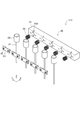
- FIG. 4 is a schematic perspective view illustrating a part of the coating head according to the first embodiment.
- the coating head 110 includes a coating bar 10, a plurality of nozzles 20 (see FIG. 3), a first member 31, and a plurality of first members. It includes two members 32 (see FIG. 3), a plurality of third members 33 (see FIG. 3), a plurality of elastic members 35 (see FIG. 3), and a position control unit 40 (see FIG. 2A).
- the plurality of nozzles 20, the first member 31, the plurality of second members 32, and the plurality of third members 33 are included in the head portion 30 (see FIG. 1A).
- the coating bar 10 can face the member to be coated 80.
- the plurality of nozzles 20 can supply the liquid 84 toward the coating bar 10.
- the plurality of nozzles 20 are, for example, needle nozzles.
- FIG. 1A corresponds to a state in which the liquid 84 is not supplied.
- FIG. 1B corresponds to a state in which the liquid 84 is being supplied.
- a gap is provided between the coating bar 10 and the member to be coated 80.
- FIG. 1B when the liquid 84 is supplied to the coating bar 10, a meniscus is formed between the coating bar 10 and the member to be coated 80. In this way, the coating bar 10 can form a meniscus of the liquid 84 between the coating bar 10 and the member to be coated 80.
- the coating film 85 is formed by the liquid 84 applied to the member 80 to be coated. When the coating film 85 is solidified, the desired film can be obtained.
- the direction from the member to be coated 80 to the coating bar 10 is the Z-axis direction.
- One direction perpendicular to the Z-axis direction is defined as the X-axis direction.
- the direction perpendicular to the Z-axis direction and the X-axis direction is defined as the Y-axis direction.
- the member to be coated 80 moves relative to the coating bar 10 along the moving direction 88.
- the moving direction 88 is, for example, along the X-axis direction.
- the coating bar 10 extends in the Y-axis direction.
- the coating bar 10 is cylindrical.
- the plurality of nozzles 20 extend in a direction inclined with respect to the Z-axis direction toward the coating bar 10.
- one of the plurality of nozzles 20 includes a nozzle portion 21 and a base portion 22.
- the nozzle portion 21 is located between one of the plurality of first recesses 31d and one of the plurality of third members 33.
- the base 22 is not between one of the plurality of first recesses 31d and one of the plurality of third members 33.
- the base 22 is provided above, for example, the first member 31.
- the nozzle portion 21 may be detachable from the base portion 22.
- the supply pipe 25 is connected to the base 22.
- the liquid 84 is supplied to the base 22 via the supply pipe 25. The liquid 84 is discharged from the nozzle portion 21.
- FIG. 3 illustrates the head portion 30.
- the first member 31 includes a plurality of first recesses 31d.
- at least a part of one of the plurality of nozzles 20 is between one of the plurality of first recesses 31d and one of the plurality of third members 33.
- At least a part of one of the plurality of nozzles 20 is, for example, a nozzle portion 21.
- At least a part of one of the plurality of nozzles 20 (for example, the nozzle portion 21) and one of the plurality of third members 33 are fixed to the first member 31 by one of the plurality of second members 32. Will be done.
- the first member 31 is a base to which a plurality of nozzles 20 are attached.
- the plurality of second members 32 are fixing members such as screws, for example.
- the first member 31 is provided with a hole or the like into which a fixing member such as a screw is fitted.
- each of the plurality of third members 33 is provided with a hole through which a fixing member such as a screw passes.
- a fixing member such as a screw passes through holes of a plurality of third members (fixing members) and is fixed to the first member 31.
- One of a plurality of nozzles 20 is provided between the first member 31 and one of the plurality of third members 33.
- One of the plurality of nozzles 20 is fixed to the first member 31 by being sandwiched between the first member 31 and one of the plurality of third members 33.
- the plurality of third members 33 are holding members.
- one of the plurality of elastic members 35 is provided at the first position px1.
- the first position px1 is between one of the plurality of third members 33 and one of the plurality of second members 32.
- the position control unit 40 controls the relative position between the plurality of nozzles 20 and the coating bar 10.
- the position control unit 40 includes the first holding unit 41 and the second holding unit 42, and the first holding unit 41 holds the coating bar 10.
- the second holding portion 42 holds a plurality of nozzles 20.
- the second holding unit 42 holds a plurality of nozzles 20 by holding the first member 31.
- the relative positions between the coating bar 10 and the plurality of nozzles 20 can be controlled.
- the liquid 84 is supplied from the plurality of nozzles 20 toward the coating bar 10. This allows the meniscus to spread evenly over a wide area.
- the plurality of nozzles 20 are stably fixed at positions guided by the plurality of first recesses 31d. As a result, the positions of the tips of the plurality of nozzles 20 can be easily aligned. Since the plurality of nozzles 20 are fixed at positions guided by the plurality of first recesses 31d, the pitches of the plurality of nozzles 20 can be set to a desired state.
- the elastic member 35 By fixing using the elastic member 35, it is possible to suppress fluctuations in the coating state due to vibration of the coating bar 10 or the like. For example, even when the supply pump of the liquid 84 has pulsation, the elastic member 35 can easily reduce the influence of pulsation.
- an appropriate force is applied to the plurality of third members 33.
- the plurality of nozzles 20 are held by the first member 31 and the plurality of third members 33 with an appropriate force.
- a plurality of nozzles 20 can be fixed with appropriate tolerance.
- the amount of the liquid 84 discharged from the plurality of nozzles 20 and adhering to the coating bar 10 can be maintained appropriately.
- a uniform coating film 85 can be formed on the member to be coated 80.
- the thickness uniformity is high.
- the position control unit 40 includes, for example, an actuator. At least one of the first holding portion 41 and the second holding portion 42 may include an actuator. For example, the relative positional relationship between the coating bar 10 and the plurality of nozzles 20 can be set satisfactorily.
- the first holding portion 41 may include, for example, a uniaxial actuator (for example, a Z actuator).
- the second holding portion 42 may include, for example, a multi-axis actuator (for example, an XZ ⁇ actuator).
- the coating head 110 may include the first sensors 51a and 51b.
- the first sensors 51a and 51b detect, for example, the distance between the coating bar 10 and the member to be coated 80.
- the coating head 110 may include a control unit 70.
- the control unit 70 obtains, for example, the detection results of the first sensors 51a and 51b, and controls the position control unit 40 (for example, the first holding unit 41) based on the detection results.
- the control unit 70 appropriately controls the distance between the coating bar 10 and the member to be coated 80.
- the first sensors 51a and 51b include, for example, an optical element.
- the first sensors 51a and 51b may include, for example, a camera.
- the coating head 110 may include the second sensors 52a and 52b.
- the second sensors 52a and 52b detect the stress between the plurality of nozzles 20 and the coating bar 10.
- the control unit 70 obtains, for example, the detection results of the second sensors 51a and 52b, and controls the position control unit 40 (for example, the second holding unit 42) based on the detection results.
- the control unit 70 appropriately controls the relative positions of the coating bar 10 and the plurality of nozzles 20.
- the plurality of elastic members 35 may be provided at a second position or a third position in addition to the first position px1. Examples of these positions will be described later.
- the elastic member 35 includes, for example, a spring.
- the spring includes at least one of a coil spring, a leaf spring, and a disc spring.
- the elastic member 35 may contain a resin such as rubber. When the elastic member 35 includes a spring, it is easy to control the force satisfactorily. When the elastic member 35 includes a coil spring, it is easier to control the force better.
- the plurality of nozzles 20 are in contact with the coating bar 10.
- the positions of the plurality of nozzles 20 with respect to the coating bar 10 are stabilized.
- a stable supply of the liquid 84 becomes possible. Since the plurality of nozzles 20 are in contact with the coating bar 10, the uniformity of the coating film 85 is higher than in the case where the plurality of nozzles 20 are not in contact with the coating bar 10.
- the position control unit 40 (for example, at least one of the first holding unit 41 and the second holding unit 42) causes the plurality of nozzles 20 to be in contact with the coating bar 10 and the plurality of nozzles 20 to be separated from the coating bar 10. It may be possible to form a state in which the nozzle is formed.
- the plurality of nozzles 20 and the coating bar 10 can move relatively in the X-axis direction.
- At least one of the first holding portion 41 and the second holding portion 42 has a stress having at least one of the directions from the coating bar 10 to the plurality of nozzles 20 and the orientation from the plurality of nozzles 20 to the coating bar 10. , It may be possible to add to at least one of the coating bar 10 and the plurality of nozzles 20.
- FIG. 5A and 5 (b) are schematic side views illustrating a part of the coating head according to the first embodiment.
- FIG. 5A shows a state in which the plurality of nozzles 20 are separated from the coating bar 10.
- FIG. 5B shows a state in which the plurality of nozzles 20 are in contact with the coating bar 10.
- the stress generated by at least one of the first holding portion 41 and the second holding portion 42 is applied to at least one of the coating bar 10 and the plurality of nozzles 20.
- at least one of the plurality of nozzles 20 may reversibly bend in response to this stress.
- the plurality of nozzles 20 may have appropriate flexibility.
- the plurality of nozzles 20 may be flexible.
- each (one) of the plurality of nozzles 20 includes the end face 21f in a state where the plurality of nozzles 20 are separated from the coating bar 10.
- the liquid 84 is discharged from the end face 21f.
- the angle ⁇ 1 between the end face 21f and the extending direction Dx in which each (one) of the plurality of nozzles 20 extends is preferably, for example, about 90 degrees. In the embodiment, the angle ⁇ 1 is, for example, 80 degrees or more and 100 degrees or less.
- the length of the nozzle 20 is, for example, 2 cm or more and 10 cm or less.
- the length of the nozzle 20 may be, for example, 3 cm or more and 6 cm or less.
- the inner diameter of the nozzle 20 is 0.15 mm or more and 2 mm or less. When the inner diameter is 0.15 mm or more, the requirement for the pump pressure for supplying the liquid 84 to the nozzle 20 is relaxed. When the inner diameter is 2 mm or less, the pulsation of the liquid 84 is easily suppressed. This makes it easier to obtain a more uniform coating film.
- FIG. 6 is a schematic perspective view illustrating a part of the coating head according to the first embodiment.
- FIG. 6 illustrates the first member 31 and the plurality of nozzles 20.
- the first member 31 and the plurality of nozzles 20 are drawn so as to be separated from each other so that the figure can be easily seen.
- the first member 31 is provided with a plurality of first recesses 31d.
- Each (one) of the plurality of first recesses 31d extends along the direction in which at least a part (for example, the nozzle portion 21) of each (one) of the plurality of nozzles 20 extends. At least a part of the nozzle portion 21 fits into such a first recess 31d. The position of the nozzle portion 21 is stable.
- each (one) of the plurality of first recesses 31d may be curved.
- the cross-sectional shape of the first recess 31d is "U-shaped".
- the cross-sectional shape of the first recess 31d may be "V-shaped”.
- the cross-sectional shape may be rectangular.
- the radius of curvature of the cross-sectional shape of the first recess 31d is, for example, equal to or greater than the radius of curvature of the cross-sectional shape of the outer surface of the nozzle portion 21.
- At least a part of the nozzle portion 21 enters the first recess 31d.
- another portion of the nozzle portion 21 is outside the first recess 31d.
- the length of the portion of the nozzle portion 21 outside the first recess 31d is 1/3 or more and 2/3 or less of the outer diameter of the nozzle portion 21.
- the outer diameter 21d of the nozzle portion 21 is, for example, 0.4 mm or more and 3 mm or less.
- the length 31dL (see FIG. 6) of the first recess 31d is, for example, 1 cm or more and 3 cm or less.
- FIG. 7 is a schematic view illustrating the coating head according to the first embodiment.
- FIG. 7 is a top view of a part of the coating head.
- the second member 32, the third member 33, and the elastic member 35 are omitted.
- a plurality of nozzles 20 may be provided in a part of the plurality of first recesses 31d.
- the pitch of the plurality of nozzles 20 is larger than the pitch of the plurality of first recesses 31d.
- Nozzles 20 are not provided in some of the plurality of first recesses 31d.
- the pitches of the plurality of nozzles 20 may be changed according to the characteristics of the liquid 84. For example, by providing the plurality of first recesses 31d at a small pitch and providing the plurality of nozzles 20 in a part of the plurality of first recesses 31d, the pitches of the plurality of nozzles 20 can be easily changed.
- the cross-sectional shape of the coating bar 10 is arbitrary.
- the cross-sectional shape of the coating bar is, for example, circular, flat circular or polygonal. A part of the cross-sectional shape may be curved, and the other part may be straight.
- the cross-sectional shape of the surface of the coating bar 10 facing the member to be coated 80 may be curved.
- the surface 10s (for example, the side surface) of the coating bar 10 is in contact with the plurality of nozzles 20.
- the surface 10s may be a curved surface.
- the surface 10s may be a flat surface. When the surface 10s is flat, for example, the contact state between the plurality of nozzles 20 and the coating bar 10 tends to be uniform.
- the coating bar 10 includes, for example, at least one selected from the group consisting of stainless steel, aluminum, titanium and glass.
- the coating bar 10 more preferably contains steleste or aluminum. This facilitates the possibility of the coating bar 10.
- the surface of the coating bar 10 is a mirror surface.
- the surface of the coating bar 10 may include fine irregularities. When fine irregularities are provided, for example, high wettability with respect to the liquid 84 can be obtained.
- the maximum height Rz of the unevenness is, for example, 5 ⁇ m or more and 50 ⁇ m or less.
- the arithmetic mean surface roughness Ra of the unevenness is, for example, 1 ⁇ m or more and 10 ⁇ m or less.
- the sandblasting method creates irregularities.
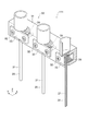
- FIG. 8 is a schematic perspective view illustrating a part of the coating head according to the first embodiment.
- FIG. 9 is a schematic exploded perspective view illustrating a part of the coating head according to the first embodiment.
- FIG. 10 is a schematic view illustrating a part of the coating head according to the first embodiment.
- FIG. 10 is a top view of a part of the coating head. 8 to 10 exemplify the head portion 30 of the coating head 111 according to the embodiment.
- the configuration of the coating head 111 excluding the head portion 30 may be the same as that of the coating head 110.
- an example of the head portion 30 of the coating head 111 will be described.
- the head portion 30 includes a plurality of nozzles 20, a first member 31, a plurality of second members 32, a plurality of third members 33, and a plurality of elastic members 35.
- the first member 31 includes a plurality of first recesses 31d. At least one part of the plurality of nozzles 20 is between one of the plurality of first recesses 31d and one of the plurality of third members 33. At least one of the above-mentioned ones of the plurality of nozzles 20 and the above-mentioned one of the plurality of third members 33 are fixed to the first member 31 by one of the plurality of second members 32.
- One of the plurality of elastic members 35 is provided at the second position px2 (see FIG. 10).
- the second position px2 is between at least one of the above-mentioned one of the plurality of first recesses 31d and the above-mentioned one of the plurality of nozzles 20.
- the coating head 111 including such a head portion 30 it is possible to provide a coating head capable of forming a uniform coating film 85.
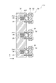
- FIG. 11 is a schematic view illustrating a part of the coating head according to the first embodiment.
- FIG. 11 is a top view of a part of the coating head.
- FIG. 11 illustrates the head portion 30 of the coating head 112 according to the embodiment.
- the configuration of the coating head 112 excluding the head portion 30 may be the same as that of the coating head 110.
- an example of the head portion 30 of the coating head 112 will be described.
- the head portion 30 includes a plurality of nozzles 20, a first member 31, a plurality of second members 32, a plurality of third members 33, and a plurality of elastic members 35.
- the first member 31 includes a plurality of first recesses 31d.
- one of the plurality of elastic members 35 is provided at the third position px3.
- the third position px3 is between at least one part of the plurality of nozzles 20 and one of the plurality of third members 33.
- the coating head 112 including such a head portion 30 it is possible to provide a coating head capable of forming a uniform coating film 85.
- one of the plurality of third members 33 includes a second recess 32d. At least a part of one of the plurality of nozzles 20 is between one of the plurality of first recesses 31d and the second recess 32d. By providing the second recess 32d, the accuracy of the positions of the plurality of nozzles 20 can be further improved.
- the elastic member 35 may be provided at at least one of the above-mentioned first position px1, the above-mentioned second position px2, and the above-mentioned third position px3.
- FIG. 12 is a schematic view illustrating a part of the coating head according to the first embodiment.
- one of the plurality of nozzles 20 includes a nozzle portion 21 and a base portion 22.
- the nozzle portion 21 and the base portion 22 are removable. This facilitates, for example, cleaning of the nozzle portion 21 and the base portion 22.
- at least one of the nozzle portion 21 and the base portion 22 can be easily replaced.
- the bottom of the base 22 is provided on top of the first member 31. As a result, the tips of the plurality of nozzles 20 can be easily aligned.
- FIG. 13 is a schematic view illustrating the coating device according to the second embodiment.
- the coating device 210 according to the embodiment includes a coating head (in this example, the coating head 110) and a supply unit 61 according to the first embodiment.
- the supply unit 61 supplies the liquid 84 to the plurality of nozzles 20.
- the supply unit 61 includes, for example, a pump.
- a tank 65 for storing the liquid 84 is provided.
- the supply unit 61 is connected to the tank 65.
- the supply unit 61 is connected to the nozzle 20 by the supply pipe 25.
- the liquid 84 is supplied from the supply unit 61 to the nozzle 20, and the liquid 84 is supplied from the nozzle 20 toward the coating bar 10.
- the coating head included in the coating device 210 may be any coating head according to the first embodiment.
- a liquid sensor 63 may be provided.
- the liquid sensor 63 detects the supply speed of the liquid 84 to the plurality of nozzles 20.
- the liquid sensor 63 measures the flow rate of the liquid 84 by utilizing, for example, the Doppler effect.
- a supply control unit 75 may be provided.
- the supply control unit 75 controls the supply unit 61 based on the supply speed detected by the liquid sensor 63. This makes it easier to obtain a more uniform coating film.
- FIG. 14 is a schematic view illustrating the coating device according to the second embodiment.
- the coating device 210 may include a member to be coated member holding portion 66.
- the member to be coated 66 holds the member 80 to be coated.
- the member to be coated 66 moves the member to be coated 80 relative to the coating head (in this example, the coating head 110).
- the member to be coated 80 includes a roll-shaped film.
- the member to be coated member holding portion 66 includes a first holding mechanism 66a and a second holding mechanism 66b.
- the first holding mechanism 66a holds the first portion 80a of the roll-shaped film (member to be coated 80).
- the second holding mechanism 66b holds the second portion 80b of the roll-shaped film (member to be coated 80).
- the first holding mechanism 66a and the second holding mechanism 66b are, for example, rollers.
- a meniscus of the liquid 84 is formed between the coating bar 10 and the member 80 to be coated, and the liquid 84 is applied to the member 80 to be coated.
- a coating film 85 made of the liquid 84 is formed on the member 80 to be coated. The coating film 85 is dried and solidified to obtain the desired film.
- the coating device 210 may include a mechanism that can change the position of the coating head 110.
- the member to be coated 80 is preferably a roll-shaped film. High productivity can be applied.
- At least a part of the position of the member to be coated holding portion 66 is higher than the position of the supply portion 61.
- the position of the first holding mechanism 66a is higher than the position of the supply unit 61.
- the moving direction 88 of the member to be coated 80 is preferably the direction from the bottom to the top. This adds gravity to the meniscus. As a result, a uniform coating film 85 can be easily obtained even when the coating film is applied at high speed.
- the moving direction 88 may be inclined with respect to the vertical direction. The angle between the moving direction 88 and the vertical direction is, for example, 30 ° or less.
- the plurality of nozzles 20 supply the liquid 84 to the coating bar 10 from above the coating bar 10. For example, dripping of the liquid 84 can be suppressed.
- a joint may be provided so that the supply pipe 25 and the nozzle 20 can be attached and detached.
- a plurality of supply pipes 25 for supplying the liquid 84 from one tank 65 to the plurality of nozzles 20 are provided. This makes it easier to supply the liquid to the plurality of nozzles 20, for example, with a uniform pressure.
- a cleaning mechanism for cleaning the coating bar 10 may be provided.
- the cleaning mechanism sprays or radiates, for example, a solvent (eg, water).
- the cleaning mechanism may be capable of applying ultrasonic waves, for example.
- a recovery mechanism for recovering excess liquid may be provided.
- FIG. 15 is a schematic view illustrating the coating device according to the second embodiment.
- the supply unit 61 may include a plurality of pumps 61p.
- the number of the plurality of nozzles 20 is an integral multiple of the plurality of pumps 61p. Thereby, the number of pumps 61p can be reduced. It is more preferable that the number of nozzles 20 to which the liquid 84 is supplied from one pump 61p is 2 n (n is an integer).
- the third embodiment relates to a coating method.
- the liquid 84 is applied to the member 80 to be coated by the coating head according to the first embodiment.
- the liquid 84 is applied to the member to be coated 80 by the coating apparatus according to the second embodiment.
- a coating method capable of forming a uniform coating film can be provided.
- the pitch of the plurality of nozzles 20 may be determined based on the viscosity of the liquid 84 and the surface tension of the liquid 84.
- a processing unit that outputs an appropriate pitch from the viscosity and surface tension may be provided.
- a film contained in a solar cell may be formed by the coating head according to the embodiment.
- the member to be coated 80 is a roll-shaped film.
- the member 80 to be coated is a roll-shaped PET film.
- the width of the PET film (length in the Y-axis direction) is 300 mm.
- a light-transmitting conductive film is formed on a roll-shaped film by a roll-to-roll sputtering apparatus.
- the conductive film is an ITO / Ag alloy / ITO laminated film.
- the sheet resistance of the conductive film is about 5 ⁇ / ⁇ .
- the conductive film is patterned into a desired shape by laser irradiation.
- the cross-sectional shape of the coating bar 10 is substantially trapezoidal.
- the bottom of the cross-sectional shape of the coating bar 10 is an arc shape having a curvature of 80 mm.
- the length of the coating bar 10 in the Y-axis direction is 300 mm.
- the coating bar 10 is SUS303.
- the length of the first member 31 in the Y-axis direction is 320 mm.
- the pitch of the plurality of first recesses 31d is 20 mm.
- the cross-sectional shape of the first recess 31d is "V-shaped".
- the length of the plurality of third members 33 in the Y-axis direction is 30 mm.
- the length of the nozzle 20 is about 50 mm.
- the nozzle 20 contains stainless steel.
- the inner diameter of the nozzle 20 is 0.8 mm.
- the nozzle 20 is fixed to the first recess 31d of the first member 31 by the second member 32 by using the third member 33 and the spring (elastic member 35).
- the supply pipe 25 is connected to the base 22 of the nozzle 20.
- the supply pipe 25 is a fluororesin tube.
- the base 22 and the supply pipe 25 are connected by a detachable connecting member.
- the first liquid is a PEDOT / PSS aqueous dispersion.
- the first liquid is one of the liquids 84. From the first liquid, for example, a hole transport layer of a solar cell can be produced.
- the first liquid is supplied from the plurality of nozzles 20 toward the coating bar 10.
- the discharge amount of the first liquid from one of the plurality of nozzles 20 is, for example, 20 ⁇ L / s.
- the moving speed of the member 80 to be coated is about 83 mm / s.
- the coating film 85 with the first liquid is dried in a roll-to-roll compatible hot air drying oven.
- the second liquid is applied onto the above-mentioned coating film 85 (hole transport layer) after drying.
- 8 mg of PTB7 [poly ⁇ 4,8-bis [(2-ethylhexyl) oxy] benzo [1,2-b: 4,5-b'] dithiophene- 2,6-diyl-1t-alt-3-fluoro-2-[(2-ethylhexyl) carbonyl] thieno [3,4-b] thiophene-4,6-diyl ⁇ ] / p-type semiconductor
- PC70BM [6,6] phenyl C71 methyl ester butylate / n-type semiconductor
- the distance between the application bar 10 and the member to be applied 80 is 300 ⁇ m.
- the discharge amount of the second liquid from one of the plurality of nozzles 20 is, for example, 40 ⁇ L / s.
- the moving speed of the member 80 to be coated is about 83 mm / s.
- the coating film 85 with the second liquid is dried in a roll-to-roll compatible hot air drying oven.
- the thickness unevenness of the coating film 85 by the first liquid and the coating film 85 by the second liquid is 5% or less.
- the coating bar 10 contains minute irregularities.
- the maximum height Rz of the unevenness is about 20 ⁇ m.
- the arithmetic mean surface roughness Ra of the unevenness is about 3 ⁇ m.
- the discharge amount of the first liquid from one of the plurality of nozzles 20 is, for example, 25 ⁇ L / s.
- the discharge amount of the first liquid from one of the plurality of nozzles 20 is, for example, 45 ⁇ L / s.
- the thickness unevenness of the coating film 85 by the first liquid and the coating film 85 by the second liquid is 7% or less.
- the elastic member 35 is not provided in the coating head.
- Other conditions in the third experiment are the same as in the first experiment.
- the thickness unevenness of the coating film 85 by the first liquid is 10% or more.
- the unevenness of the thickness of the coating film 85 due to the second liquid is 10% or more.
- the first member 31 is not provided with the first recess 31d in the coating head.
- Other conditions in the fourth experiment are the same as in the first experiment.
- the thickness unevenness of the coating film 85 by the first liquid is 15% or more.
- the unevenness of the thickness of the coating film 85 due to the second liquid is 15% or more.
- the plurality of nozzles 20 cannot uniformly contact the coating bar 10.
- a low-cost solar cell can be obtained by forming a layer contained in the solar cell by coating.
- roll-to-roll coating provides a uniform coating film.
- a meniscus is formed between the coating bar 10 and the member to be coated 80.
- the positions of the plurality of nozzles 20 are determined by using the groove (first recess 31d) as a guide.
- a plurality of nozzles 20 are fixed to the first member 31 by using the elastic member 35.
- the embodiment includes the following configurations (eg, technical proposals).
- a plurality of elastic members one of the plurality of elastic members is provided at at least one of the first position, the second position, and the third position, and the first position is the plurality of third members.
- the second position is between the at least a portion of the one of the plurality of first recesses and the one of the plurality of nozzles.
- the third position is the plurality of elastic members, which are between the at least a part of the one of the plurality of nozzles and the one of the plurality of third members.
- a position control unit that controls the relative position between the plurality of nozzles and the coating bar, Coating head with.
- (Structure 2) The coating head according to configuration 1, wherein the plurality of nozzles are in contact with the coating bar.
- (Structure 3) The coating head according to configuration 1 or 2, wherein the one of the plurality of first recesses extends along a direction in which at least a part of the one of the plurality of nozzles extends.
- (Structure 4) The surface of the coating bar contains irregularities and The coating head according to any one of configurations 1 to 3, wherein the maximum height Rz of the unevenness is 5 ⁇ m or more and 50 ⁇ m or less.
- (Structure 5) The coating head according to any one of configurations 1 to 4, wherein the plurality of elastic members include a spring.
- the one of the plurality of nozzles includes an end face for discharging the liquid.
- the coating head according to any one of configurations 1 to 7, wherein the angle between the end face and the extending direction in which the one of the plurality of nozzles extends is 80 degrees or more and 100 degrees or less.
- the one of the plurality of nozzles includes a nozzle portion and a base portion.
- the nozzle portion is removable from the base portion and is removable.
- the liquid is supplied to the base and The coating head according to any one of configurations 1 to 8, wherein the liquid is discharged from the nozzle portion.
- the nozzle portion is located between the one of the plurality of first recesses and the one of the plurality of third members.
- the coating head according to any one of configurations 1 to 10 wherein the coating bar can form a meniscus of the liquid between the coating bar and the member to be coated.
- the one of the plurality of third members includes a second recess.
- the coating head according to any one of configurations 1 to 11, wherein at least a part of the one of the plurality of nozzles is located between the one of the plurality of first recesses and the second recess. .. (Structure 13)
- the position control unit A first holding portion for holding the coating bar and A second holding unit that holds the plurality of nozzles, Including At least one of the first holding portion and the second holding portion has a stress having at least one of the directions from the coating bar to the plurality of nozzles and the direction from the plurality of nozzles to the coating bar.
- the coating head according to any one of configurations 1 to 12, which can be added to at least one of the coating bar and the plurality of nozzles. (Structure 14) 13.
- the member to be coated includes a roll-shaped film and includes a roll-shaped film.
- the member holding portion to be coated is A first holding mechanism for holding the first portion of the roll-shaped film, and A second holding mechanism for holding the second portion of the roll-shaped film, and 15.
- the supply unit includes a plurality of pumps.
- (Structure 20) A coating method for applying the liquid to the member to be coated by the coating head according to any one of the configurations 1 to 14.
- a coating head, a coating device, and a coating method capable of forming a uniform coating film are provided.
- the present invention has been described above with reference to specific examples. However, the present invention is not limited to these specific examples.
- the present invention is similarly carried out by appropriately selecting from a range known to those skilled in the art. Is included in the scope of the present invention as long as the effect of the above can be obtained.
- 10 ... coating bar 10s ... surface, 20 ... nozzle, 21 ... nozzle part, 21d ... outer diameter, 21f ... end face, 22 ... base, 25 ... supply pipe, 30 ... head part, 31-33 ... 1st to 3rd Member, 31d ... 1st recess, 31dL ... Length, 32d ... 2nd recess, 35 ... Elastic member, 40 ... Position control unit, 41, 42 ... Holding unit, 51a, 51b ... 1st sensor, 52a, 52b ... First 2 sensors, 61 ... Supply unit, 61p ... Pump, 63 ... Liquid sensor, 65 ... Tank, 66 ... Member to be coated, 66a, 66b ...
- 1st and 2nd holding mechanisms 70 ... Control unit, 75 ... Supply control Part, 80 ... member to be coated, 80a, 80b ... first and second parts, 84 ... liquid, 85 ... coating film, 88 ... moving direction, ⁇ 1 ... angle, 110-112 ... coating head, 210 ... coating device, Dx ... Extension direction, px1 to px3 ... 1st to 3rd positions
Landscapes
- Coating Apparatus (AREA)
Abstract
均一な塗布膜を形成できる塗布ヘッド、塗布装置及び塗布方法を提供する。実施形態によれば、塗布ヘッドは、塗布バー、複数のノズル、第1~第3部材、弾性部材及び位置制御部を含む。複数のノズルは、塗布バーに向けて液を供給する。第1部材は、複数の第1凹部を含む。複数のノズルの1つの少なくとも一部は、複数の第1凹部の1つと、複数の第3部材の1つと、の間にある。複数のノズルの1つの少なくとも一部、及び、複数の第3部材の1つは、複数の第2部材の1つにより第1部材に固定される。複数の弾性部材の1つは、第1~第3位置の少なくともいずれかに設けられる。第1位置は、複数の第3部材の1つと複数の第2部材の1つとの間である。第2位置は、複数の第1凹部の1つの少なくとも一部と複数のノズルの1つとの間である。第3位置は、複数のノズルの1つの少なくとも一部と複数の第3部材の1つとの間である。
Description
本発明の実施形態は、塗布ヘッド、塗布装置及び塗布方法に関する。
塗布バーを用いて液を塗布する塗布ヘッドがある。均一な塗布膜を形成できる塗布装置が望まれる。
本発明の実施形態は、均一な塗布膜を形成できる塗布ヘッド、塗布装置及び塗布方法を提供する。
本発明の実施形態によれば、塗布ヘッドは、塗布バー、複数のノズル、第1部材、第2部材、第3部材、弾性部材及び位置制御部を含む。前記塗布バーは、被塗布部材と対向可能である。前記複数のノズルは、前記塗布バーに向けて液を供給することが可能である。前記第1部材は、複数の第1凹部を含む。前記複数のノズルの1つの少なくとも一部は、前記複数の第1凹部の1つと、前記複数の第3部材の1つと、の間にある。複数のノズルの前記1つの前記少なくとも一部、及び、前記複数の第3部材の前記1つは、前記複数の前記第2部材の1つにより前記第1部材に固定される。前記複数の弾性部材の1つは、第1位置、第2位置及び第3位置の少なくともいずれかに設けられる。前記第1位置は、前記複数の第3部材の前記1つと前記複数の第2部材の前記1つとの間である。前記第2位置は、前記複数の第1凹部の前記1つの前記少なくとも一部と前記複数のノズルの前記1つとの間である。前記第3位置は、前記複数のノズルの前記1つの前記少なくとも一部と前記複数の第3部材の前記1つとの間である。前記位置制御部は、前記複数のノズルと前記塗布バーとの間の相対的な位置を制御する。
以下、本発明の実施の形態について図面を参照して詳細に説明する。
なお、図面は模式的または概念的なものであり、各部分の厚さと幅との関係、部分間の大きさの比率などは、必ずしも現実のものと同一とは限らない。また、同じ部分を表す場合であっても、図面により互いの寸法や比率が異なって表される場合もある。
なお、本願明細書と各図において、既出の図に関して前述したものと同様の要素には同一の符号を付して詳細な説明は適宜省略する。
なお、図面は模式的または概念的なものであり、各部分の厚さと幅との関係、部分間の大きさの比率などは、必ずしも現実のものと同一とは限らない。また、同じ部分を表す場合であっても、図面により互いの寸法や比率が異なって表される場合もある。
なお、本願明細書と各図において、既出の図に関して前述したものと同様の要素には同一の符号を付して詳細な説明は適宜省略する。
(第1実施の形態)
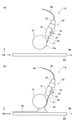
図1(a)及び図1(b)は、第1実施形態に係る塗布ヘッドの一部を例示する模式的側面図である。
図2(a)及び図2(b)は、第1実施形態に係る塗布ヘッドを例示する模式図である。図2(a)は上面図である。図2(b)は、側面図である。図2(b)においては、図を見やすくするために、一部の要素が省略されている。
図3は、第1実施形態に係る塗布ヘッドを例示する模式図である。図3は、塗布ヘッドの一部の上面図である。
図4は、第1実施形態に係る塗布ヘッドの一部を例示する模式的斜視図である。
図1(a)及び図1(b)は、第1実施形態に係る塗布ヘッドの一部を例示する模式的側面図である。
図2(a)及び図2(b)は、第1実施形態に係る塗布ヘッドを例示する模式図である。図2(a)は上面図である。図2(b)は、側面図である。図2(b)においては、図を見やすくするために、一部の要素が省略されている。
図3は、第1実施形態に係る塗布ヘッドを例示する模式図である。図3は、塗布ヘッドの一部の上面図である。
図4は、第1実施形態に係る塗布ヘッドの一部を例示する模式的斜視図である。
図1(a)、図2(a)及び図3に示すように、実施形態に係る塗布ヘッド110は、塗布バー10、複数のノズル20(図3参照)、第1部材31、複数の第2部材32(図3参照)、複数の第3部材33(図3参照)、複数の弾性部材35(図3参照)及び、位置制御部40(図2(a)参照)を含む。複数のノズル20、第1部材31、複数の第2部材32、及び、複数の第3部材33は、ヘッド部30(図1(a)参照)に含まれる。
図1(a)に示すように、塗布バー10は、被塗布部材80と対向可能である。
図1(b)に示すように、複数のノズル20は、塗布バー10に向けて液84を供給することが可能である。複数のノズル20は、例えば、ニードルノズルである。図1(a)は、液84が供給されていない状態に対応する。図1(b)は、液84が供給されている状態に対応する。図1(a)に示すように、塗布バー10と被塗布部材80との間には、間隙が設けられる。図1(b)に示すように、液84が塗布バー10に供給されると、塗布バー10と被塗布部材80との間にメニスカスが形成される。このように、塗布バー10は、塗布バー10と被塗布部材80との間に、液84のメニスカスを形成可能である。被塗布部材80に塗布された液84により塗布膜85が形成される。塗布膜85が固体化することで、目的とする膜が得られる。
図1(a)に示すように、被塗布部材80から塗布バー10への方向をZ軸方向とする。Z軸方向に対して垂直な1つの方向をX軸方向とする。Z軸方向及びX軸方向に対して垂直な方向をY軸方向とする。
図1(a)に示すように、被塗布部材80は、塗布バー10に対して、移動方向88に沿って、相対的に移動する。移動方向88は、例えば、X軸方向に沿う。
図4に示すように、塗布バー10は、Y軸方向に延びる。1つの例において、塗布バー10は、円筒状である。
図1(a)に示すように、1つの例において、複数のノズル20は、塗布バー10に向かって、Z軸方向に対して傾斜する方向に延びる。
図1(a)に示すように、この例では、複数のノズル20の1つは、ノズル部21と、基部22と、を含む。この例では、ノズル部21は、複数の第1凹部31dの1つと、複数の第3部材33の1つと、の間にある。基部22は、複数の第1凹部31dのその1つと、複数の第3部材33のその1つと、の間にない。基部22は、例えば、第1部材31の上方に設けられる。後述するように、例えば、ノズル部21は、基部22と着脱可能でも良い。例えば、基部22に供給管25が接続される。図1(b)に示すように、供給管25を介して、基部22に液84が供給される。ノズル部21から液84が吐出される。
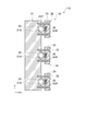
図3は、ヘッド部30を例示している。図3に示すように、第1部材31は、複数の第1凹部31dを含む。図3に示すように、複数のノズル20の1つの少なくとも一部は、複数の第1凹部31dの1つと、複数の第3部材33の1つと、の間にある。複数のノズル20の1つの上記の少なくとも一部は、例えば、ノズル部21である。複数のノズル20のその1つの少なくとも一部(例えば、ノズル部21)、及び、複数の第3部材33のその1つは、複数の第2部材32の1つにより、第1部材31に固定される。
第1部材31は、複数のノズル20が取り付けられるベースである。複数の第2部材32は、例えば、ネジなどの固定部材である。第1部材31に、ネジなどの固定部材が嵌る孔などが設けられる。例えば、複数の第3部材33のそれぞれに、ネジなどの固定部材が通る孔が設けられる。ネジなどの固定部材は、複数の第3部材(固定部材)の孔を通過して、第1部材31に固定される。第1部材31と、複数の第3部材33の1つと、の間に、複数のノズル20の1つが設けられる。複数のノズル20の1つは、第1部材31と、複数の第3部材33の1つと、の間に挟まれることで、第1部材31に固定される。複数の第3部材33は、押さえ部材である。
図3に示す例では、複数の弾性部材35の1つは、第1位置px1に設けられる。第1位置px1は、複数の第3部材33の1つと、複数の第2部材32の1つと、の間である。
図2(a)に示すように、位置制御部40は、複数のノズル20と塗布バー10との間の相対的な位置を制御する。この例では、位置制御部40は、第1保持部41及び第2保持部42を含む、第1保持部41は、塗布バー10を保持する。第2保持部42は、複数のノズル20を保持する。例えば、第2保持部42は、第1部材31を保持することで、複数のノズル20を保持する。
第1保持部41及び第2保持部42の相対的な位置が制御されることで、塗布バー10と複数のノズル20との間の相対的な位置が制御できる。
実施形態において、塗布バー10へ向けて複数のノズル20から液84が供給される。これにより、メニスカスが広い範囲に均一に広がることができる。複数のノズル20が複数の第1凹部31dをガイドにした位置に安定して固定される。これにより、複数のノズル20の先端の位置が揃いやすい。複数のノズル20が複数の第1凹部31dをガイドにした位置に固定されるため、複数のノズル20のピッチが所望の状態に設定できる。弾性部材35を用いた固定により、塗布バー10などの振動などにより塗布状態が変動することが抑制できる。例えば、液84の供給ポンプに脈動がある場合にも、弾性部材35が脈動の影響を低減しやすい。
実施形態においては、複数の弾性部材35が設けられることにより、適度な力が複数の第3部材33に加わる。複数のノズル20は、第1部材31と複数の第3部材33とにより、適度な力で保持される。例えば、複数のノズル20が適度なトレランスで固定できる。これにより、複数のノズル20から吐出され塗布バー10に付着する液84の量が適正に維持できる。これにより、被塗布部材80に均一な塗布膜85を形成できる。実施形態によれば、均一な塗布膜85を形成できる塗布ヘッドが提供できる。塗布膜85において、例えば、厚さの均一性が高い。
位置制御部40は、例えば、アクチュエータを含む。第1保持部41及び第2保持部42の少なくともいずれかは、アクチュエータを含んでも良い。例えば、塗布バー10と、複数のノズル20と、の相対的な位置関係が良好に設定できる。第1保持部41は、例えば、1軸アクチュエータ(例えばZアクチュエータ)を含んでも良い。第2保持部42は、例えば、多軸アクチュエータ(例えばXZθアクチュエータ)を含んでも良い。
図2(a)に示すように、塗布ヘッド110は、第1センサ51a及び51bを含んでも良い。第1センサ51a及び51bは、例えば、塗布バー10と被塗布部材80との間の距離を検出する。
図2(a)に示すように、塗布ヘッド110は、制御部70を含んでも良い。制御部70は、例えば、第1センサ51a及び51bによる検出結果を入手し、検出結果に基づいて、位置制御部40(例えば、第1保持部41)を制御する。制御部70により、塗布バー10と被塗布部材80との間の距離が適切に制御される。第1センサ51a及び51bは、例えば、光学素子を含む。第1センサ51a及び51bは、例えば、カメラを含んでも良い。
図2(a)に示すように、塗布ヘッド110は、第2センサ52a及び52bを含んでも良い。第2センサ52a及び52bは、複数のノズル20と塗布バー10との間の応力を検出する。制御部70は、例えば、第2センサ51a及び52bによる検出結果を入手し、検出結果に基づいて、位置制御部40(例えば、第2保持部42)を制御する。制御部70により、塗布バー10と複数のノズル20との相対的な位置が、適切に制御される。
後述するように、複数の弾性部材35は、第1位置px1の他に、第2位置または第3位置に設けられても良い。これらの位置の例については、後述する。
弾性部材35は、例えば、ばねを含む。ばねは、コイルばね、板ばね、及び、皿ばねの少なくともいずれかを含む。弾性部材35は、ゴムなどの樹脂を含んでも良い。弾性部材35がばねを含む場合、力を良好に制御し易い。弾性部材35がコイルばねを含む場合、力をより良好に制御し易い。
図1(a)に示すように、例えば、複数のノズル20は、塗布バー10と接する。これにより、複数のノズル20の塗布バー10に対する位置が安定する。安定した液84の供給が可能になる。複数のノズル20が塗布バー10と接することで、複数のノズル20が塗布バー10と接しない場合に比べて、塗布膜85の均一性が高い。
例えば、位置制御部40(例えば、第1保持部41及び第2保持部42の少なくともいずれか)により、複数のノズル20が塗布バー10に接する状態と、複数のノズル20が塗布バー10から離れた状態と、が形成可能でも良い。複数のノズル20と塗布バー10とが、相対的にX軸方向に移動できる。
第1保持部41及び第2保持部42の少なくともいずれかは、塗布バー10から複数のノズル20への向き、及び、複数のノズル20から塗布バー10への向きの少なくともいずれかを有する応力を、塗布バー10及び複数のノズル20の少なくともいずれかに加えることが可能でも良い。
図5(a)及び図5(b)は、第1実施形態に係る塗布ヘッドの一部を例示する模式的側面図である。
図5(a)は、複数のノズル20が塗布バー10から離れた状態を示している。図5(b)は、複数のノズル20が塗布バー10に接する状態を示している。例えば、第1保持部41及び第2保持部42の少なくともいずれかにより生じる応力が、塗布バー10及び複数のノズル20の少なくともいずれかに加わる。図5(b)に示すように、複数のノズル20の少なくともいずれかは、この応力に応じて可逆的に曲がっても良い。複数のノズル20は、適度な可撓性を有しても良い。複数のノズル20は、撓むことが可能でも良い。
図5(a)は、複数のノズル20が塗布バー10から離れた状態を示している。図5(b)は、複数のノズル20が塗布バー10に接する状態を示している。例えば、第1保持部41及び第2保持部42の少なくともいずれかにより生じる応力が、塗布バー10及び複数のノズル20の少なくともいずれかに加わる。図5(b)に示すように、複数のノズル20の少なくともいずれかは、この応力に応じて可逆的に曲がっても良い。複数のノズル20は、適度な可撓性を有しても良い。複数のノズル20は、撓むことが可能でも良い。
図5(a)に示すように、複数のノズル20が塗布バー10から離れた状態において、複数のノズル20のそれぞれ(1つ)は、端面21fを含む。端面21fから液84が吐出される。端面21fと、複数のノズル20のそれぞれ(1つ)が延在する延在方向Dxと、の間の角度θ1は、例えば、約90度であることが好ましい。実施形態において、角度θ1は、例えば、80度以上100度以下である。このような角度により、例えば、ノズル20の固定状態(例えば延在方向Dxを軸とする回転位置)が変化しても、塗布バー10とノズル20の先端との接触状態が変化し難い。安定した塗布がより可能である。このような角度により、塗布バー10の損傷が抑制できる。
1つの例において、ノズル20の長さは、例えば、2cm以上10cm以下である。ノズル20の長さは、例えば、3cm以上6cm以下でも良い。1つの例において、ノズル20の内径は、0.15mm以上2mm以下である。内径が0.15mm以上であることで、ノズル20への液84の供給のためのポンプ圧力への要求が緩和される。内径が2mm以下であることで、液84の脈動が抑制しやすい。これにより、より均一な塗布膜が得易い。
図6は、第1実施形態に係る塗布ヘッドの一部を例示する模式的斜視図である。
図6は、第1部材31及び複数のノズル20を例示している。図6では、図が見やすくなるように、第1部材31及び複数のノズル20が互いに離されて描かれている。
図6は、第1部材31及び複数のノズル20を例示している。図6では、図が見やすくなるように、第1部材31及び複数のノズル20が互いに離されて描かれている。
図6に示すように、第1部材31に複数の第1凹部31dが設けられている。複数の第1凹部31dのそれぞれ(1つ)は、複数のノズル20のそれぞれ(1つ)の少なくとも一部(例えばノズル部21)が延びる方向に沿って延びる。このような第1凹部31dに、ノズル部21の少なくとも一部がはまる。ノズル部21の位置が安定する。
図6に示すように、複数の第1凹部31dのそれぞれ(1つ)の少なくとも一部は、曲面状でも良い。例えば、第1凹部31dの断面形状は、「U字状」である。実施形態において、第1凹部31dの断面形状は、「V字状」でも良い。断面形状は、長方形状でも良い。第1凹部31dの断面形状が「U字状」の場合、ノズル部21に加わる力が均一化し易い。例えば、ノズル部21の損傷が抑制できる。
実施形態において、第1凹部31dの断面形状が曲面状である場合、第1凹部31dの断面形状の曲率半径は、例えば、ノズル部21の外面の断面形状の曲率半径以上である。
第1凹部31dにノズル部21の少なくとも一部が入る。1つの例において、ノズル部21の別の一部は、第1凹部31dの外にある。1つの例において、ノズル部21のうちで第1凹部31dの外にある部分の長さは、ノズル部21の外径の1/3以上2/3以下である。ノズル部21の外径21dは、例えば、0.4mm以上3mm以下である。第1凹部31dの長さ31dL(図6参照)は、例えば、1cm以上3cm以下である。
図7は、第1実施形態に係る塗布ヘッドを例示する模式図である。
図7は、塗布ヘッドの一部の上面図である。図7においては、第2部材32、第3部材33及び弾性部材35は省略されている。
図7は、塗布ヘッドの一部の上面図である。図7においては、第2部材32、第3部材33及び弾性部材35は省略されている。
図7に示すように、複数の第1凹部31dの一部に、複数のノズル20が設けられても良い。図7の例では、例えば、複数の第1凹部31dのピッチよりも、複数のノズル20のピッチは大きい。複数の第1凹部31dのいくつかには、ノズル20が設けられていない。例えば、液84の特性に応じて、複数のノズル20のピッチが変更できても良い。例えば、複数の第1凹部31dを小さいピッチで設けておき、複数の第1凹部31dの一部に複数のノズル20が設けられることで、複数のノズル20のピッチが容易に変更できる。
実施形態において、塗布バー10の断面形状は、任意である。塗布バーの断面形状は、例えば、円形、偏平円形または多角形である。断面形状の一部が曲線状で、他の部分が直線状でも良い。例えば、塗布バー10の、被塗布部材80に対向する面の断面形状は曲線状でも良い。
図1(a)に示すように、塗布バー10の面10s(例えば側面)は、複数のノズル20と接する。図1(a)に示すように、面10sは、曲面で良い。実施形態において、面10sは、平面でも良い。面10sが平面であると、例えば、複数のノズル20と塗布バー10との接触状態が均一になり易い。
塗布バー10は、例えば、ステンレススチール、アルミニウム、チタン及びガラスよりなる群から選択された少なくとも1つを含む。塗布バー10は、ステレススチールまたはアルミニウムを含むことがより好ましい。これにより、塗布バー10の可能が容易になる。1つの例において、塗布バー10の表面は鏡面である。塗布バー10の表面は、細かい凹凸を含んでも良い。細かい凹凸が設けられると、例えば、液84に対しての高い濡れ性が得られる。凹凸の最大高さRzは、例えば、5μm以上50μm以下である。凹凸の算術平均表面粗さRaは、例えば、1μm以上10μm以下である。例えば、サンドブラスト法により、凹凸が作製される。
図8は、第1実施形態に係る塗布ヘッドの一部を例示する模式的斜視図である。
図9は、第1実施形態に係る塗布ヘッドの一部を例示する模式的分解斜視図である。
図10は、第1実施形態に係る塗布ヘッドの一部を例示する模式図である。
図10は、塗布ヘッドの一部の上面図である。
図8~図10は、実施形態に係る塗布ヘッド111のヘッド部30を例示している。ヘッド部30を除く塗布ヘッド111の構成は、塗布ヘッド110と同様で良い。以下、塗布ヘッド111のヘッド部30の例について説明する。
図9は、第1実施形態に係る塗布ヘッドの一部を例示する模式的分解斜視図である。
図10は、第1実施形態に係る塗布ヘッドの一部を例示する模式図である。
図10は、塗布ヘッドの一部の上面図である。
図8~図10は、実施形態に係る塗布ヘッド111のヘッド部30を例示している。ヘッド部30を除く塗布ヘッド111の構成は、塗布ヘッド110と同様で良い。以下、塗布ヘッド111のヘッド部30の例について説明する。
図8~図10に示すように、ヘッド部30は、複数のノズル20と、第1部材31と、複数の第2部材32と、複数の第3部材33と、複数の弾性部材35と、を含む。第1部材31は、複数の第1凹部31dを含む。複数のノズル20の1つの少なくとも一部は、複数の第1凹部31dの1つと、複数の第3部材33の1つと、の間にある。複数のノズル20の上記の1つの上記の少なくとも一部、及び、複数の第3部材33の上記の1つは、複数の第2部材32の1つにより第1部材31に固定される。
複数の弾性部材35の1つは、第2位置px2(図10参照)に設けられる。第2位置px2は、複数の第1凹部31dの上記の1つの上記の少なくとも一部と、複数のノズル20の上記の1つとの間である。
このようなヘッド部30を含む塗布ヘッド111においても、均一な塗布膜85を形成できる塗布ヘッドが提供できる。
図11は、第1実施形態に係る塗布ヘッドの一部を例示する模式図である。
図11は、塗布ヘッドの一部の上面図である。
図11は、実施形態に係る塗布ヘッド112のヘッド部30を例示している。ヘッド部30を除く塗布ヘッド112の構成は、塗布ヘッド110と同様で良い。以下、塗布ヘッド112のヘッド部30の例について説明する。
図11は、塗布ヘッドの一部の上面図である。
図11は、実施形態に係る塗布ヘッド112のヘッド部30を例示している。ヘッド部30を除く塗布ヘッド112の構成は、塗布ヘッド110と同様で良い。以下、塗布ヘッド112のヘッド部30の例について説明する。
塗布ヘッド112においても、ヘッド部30は、複数のノズル20と、第1部材31と、複数の第2部材32と、複数の第3部材33と、複数の弾性部材35と、を含む。第1部材31は、複数の第1凹部31dを含む。塗布ヘッド112において、複数の弾性部材35の1つは、第3位置px3に設けられる。第3位置px3は、複数のノズル20の1つの少なくとも一部と、複数の第3部材33の1つと、の間である。
このようなヘッド部30を含む塗布ヘッド112においても、均一な塗布膜85を形成できる塗布ヘッドが提供できる。
この例では、複数の第3部材33の1つは、第2凹部32dを含む。複数のノズル20の1つの少なくとも一部は、複数の第1凹部31dの1つと、第2凹部32dと、の間にある。第2凹部32dが設けられることで、複数のノズル20の位置の精度をより高めることができる。
実施形態において、弾性部材35は、上記の第1位置px1、上記の第2位置px2、及び、上記の第3位置px3の少なくともいずれかに設けられても良い。
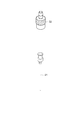
図12は、第1実施形態に係る塗布ヘッドの一部を例示する模式図である。
図12に示すように、複数のノズル20の1つは、ノズル部21及び基部22を含む。この例では、ノズル部21及び基部22は、着脱可能である。これにより、例えば、ノズル部21及び基部22の洗浄が容易になる。例えば、ノズル部21及び基部22の少なくともいずれかの交換が容易になる。例えば、基部22の底部が、第1部材31の上部に設けられる。これにより、複数のノズル20の先端が揃い易い。
図12に示すように、複数のノズル20の1つは、ノズル部21及び基部22を含む。この例では、ノズル部21及び基部22は、着脱可能である。これにより、例えば、ノズル部21及び基部22の洗浄が容易になる。例えば、ノズル部21及び基部22の少なくともいずれかの交換が容易になる。例えば、基部22の底部が、第1部材31の上部に設けられる。これにより、複数のノズル20の先端が揃い易い。
(第2実施形態)
第2実施形態は、塗布装置に係る。
図13は、第2実施形態に係る塗布装置を例示する模式図である。
図13に示すように、実施形態に係る塗布装置210は、第1実施形態に係る塗布ヘッド(この例では、塗布ヘッド110)と、供給部61と、を含む。供給部61は、複数のノズル20に液84を供給する。供給部61は、例えば、ポンプを含む。この例では、液84が蓄えられるタンク65が設けられる。供給部61は、タンク65と接続される。供給部61は、供給管25により、ノズル20と接続される。液84が供給部61からノズル20に供給され、液84がノズル20から塗布バー10に向けて供給される。塗布装置210に含まれる塗布ヘッドは、第1実施形態に係る任意の塗布ヘッドで良い。
図13に示すように、液センサ63が設けられても良い。液センサ63は、複数のノズル20への液84の供給速度を検出する。液センサ63は、例えば、ドップラー効果を利用して液84の流量を測定する。
供給制御部75が設けられても良い。供給制御部75は、液センサ63により検出された供給速度に基づいて供給部61を制御する。これにより、より均一な塗布膜が得易くなる。
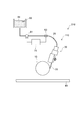
図14は、第2実施形態に係る塗布装置を例示する模式図である。
図14に示すように、塗布装置210は、被塗布部材保持部66を含んでも良い。被塗布部材保持部66は、被塗布部材80を保持する。被塗布部材保持部66は、被塗布部材80を塗布ヘッド(この例では、塗布ヘッド110)に対して相対的に移動させる。
図14に示すように、塗布装置210は、被塗布部材保持部66を含んでも良い。被塗布部材保持部66は、被塗布部材80を保持する。被塗布部材保持部66は、被塗布部材80を塗布ヘッド(この例では、塗布ヘッド110)に対して相対的に移動させる。
この例では、被塗布部材80は、ロール状フィルムを含む。被塗布部材保持部66は、第1保持機構66a及び第2保持機構66bを含む。第1保持機構66aは、ロール状フィルム(被塗布部材80)の第1部分80aを保持する。第2保持機構66bは、ロール状フィルム(被塗布部材80)の第2部分80bを保持する。第1保持機構66a及び第2保持機構66bは、例えば、ローラである。
塗布装置210において、塗布バー10と被塗布部材80との間に液84のメニスカスが形成され、液84が被塗布部材80に塗布される。被塗布部材80に液84による塗布膜85が形成される。塗布膜85が乾燥され、固体化することで、目的とする膜が得られる。
例えば、塗布装置210は、塗布ヘッド110の位置を変更できる機構を含んでも良い。被塗布部材80は、ロール状フィルムであることが好ましい。高い生産性での塗布が可能になる。
図14に示すように、被塗布部材保持部66の少なくとも一部の位置は、供給部61の位置よりも高い。この例では、第1保持機構66aの位置は、供給部61の位置よりも高い。このような構成により、例えば、供給部61の脈動の影響を抑制し易くなる。
実施形態において、被塗布部材80の移動方向88は、下から上への方向であることが好ましい。これにより、メニスカスに重力が加わる。これにより、高速で塗布した場合も、均一な塗布膜85が得易い。移動方向88は、鉛直方向に対して傾斜しても良い。移動方向88と鉛直方向との間の角度は、例えば、30°以下である。
図14に示すように、複数のノズル20は、塗布バー10の上方から液84を塗布バー10に供給することが好ましい。例えば、液84のドリッピングが抑制できる。
実施形態において、供給管25とノズル20とが脱着できるジョイントが設けられても良い。
実施形態において、例えば、1つのタンク65から複数のノズル20に液84を供給する複数の供給管25が設けられる。これにより、例えば、均一な圧力により、複数のノズル20に液を供給し易くできる。
実施形態において、塗布バー10を洗浄する洗浄機構が設けられても良い。洗浄機構は、例えば、溶媒(例えば水)を噴霧または放射する。洗浄機構は、例えば、超音波を印加可能でも良い。実施形態において、余剰の液を回収する回収機構が設けられても良い。
図15は、第2実施形態に係る塗布装置を例示する模式図である。
図15に示すように、供給部61は、複数のポンプ61pを含んでも良い。この例では、複数のノズル20の数は、複数のポンプ61pの整数倍である。これにより、ポンプ61pの数を減らすことができる。1つのポンプ61pから液84が供給されるノズル20の数は、2n(nは整数)であることがさらに好ましい。
図15に示すように、供給部61は、複数のポンプ61pを含んでも良い。この例では、複数のノズル20の数は、複数のポンプ61pの整数倍である。これにより、ポンプ61pの数を減らすことができる。1つのポンプ61pから液84が供給されるノズル20の数は、2n(nは整数)であることがさらに好ましい。
(第3実施形態)
第3実施形態は、塗布方法に係る。実施形態に係る塗布方法は、第1実施形態に係る塗布ヘッドにより、被塗布部材80に液84を塗布する。実施形態に係る塗布方法は、第2実施形態に係る塗布装置により、被塗布部材80に液84を塗布する。均一な塗布膜を形成できる塗布方法が提供できる。
第3実施形態は、塗布方法に係る。実施形態に係る塗布方法は、第1実施形態に係る塗布ヘッドにより、被塗布部材80に液84を塗布する。実施形態に係る塗布方法は、第2実施形態に係る塗布装置により、被塗布部材80に液84を塗布する。均一な塗布膜を形成できる塗布方法が提供できる。
実施形態において、複数のノズル20のピッチは、液84の粘性と液84の表面張力に基づいて定められても良い。粘性及び表面張力から適正なピッチを出力する処理部が設けられても良い。
実施形態に係る塗布ヘッドにより、例えば、太陽電池に含まれる膜が形成されても良い。例えば、被塗布部材80は、ロール状のフィルムである。
以下、実験結果の例について説明する。実験において、被塗布部材80は、ロール状のPETフィルムである。PETフィルムの幅(Y軸方向の長さ)は、300mmである。ロールツーロール対応のスパッタ装置により、ロール状のフィルム上に光透過性の導電膜が形成される。導電膜は、ITO/Ag合金/ITOの積層膜である。導電膜のシート抵抗は、約5Ω/□である。導電膜は、レーザ照射により所望の形状にパターニングされる。
実験において、塗布バー10の断面形状は、実質的に台形である。塗布バー10の断面形状の底部は、80mmの曲率を持つ円弧状である。塗布バー10のY軸方向の長さは、300mmである。塗布バー10は、SUS303である。
第1部材31のY軸方向の長さは、320mmである。複数の第1凹部31dのピッチは、20mmである。第1凹部31dの断面形状は、「V字形状」である。複数の第3部材33のY軸方向の長さは30mmである。ノズル20の長さは、約50mmである。ノズル20は、ステンレススチールを含む。ノズル20の内径は、0.8mmである。ノズル20が、第3部材33及びばね(弾性部材35)を用いて、第2部材32により、第1部材31の第1凹部31dに固定される。ノズル20の基部22に供給管25が接続される。供給管25は、フッ素樹脂製チューブである。基部22と供給管25とは、着脱可能な接続部材により接続される。
第1実験において、第1液は、PEDOT/PSS水分散液である。第1液は液84の1つである。第1液から、例えば、太陽電池のホール輸送層が作製できる。第1液が、複数のノズル20から塗布バー10に向けて供給される。複数のノズル20の1つからの第1液の吐出量は、例えば、20μL/sである。被塗布部材80の移動速度は、約83mm/sである。第1液による塗布膜85は、ロールツーロールの対応の熱風乾燥炉で乾燥される。
乾燥後の上記の塗布膜85(ホール輸送層)の上に、第2液が塗布される。第2液において、1mLのモノクロロベンゼンに対して、8mgのPTB7([ポリ{4,8-ビス[(2-エチルヘキシル)オキシ]ベンゾ[1,2-b:4,5-b’]ジチオフェン-2,6-ジイル-1t-alt-3-フルオロ-2-[(2-エチルヘキシル)カルボニル]チエノ[3,4-b]チオフェン-4,6-ジイル}]/p形半導体)と、12mgのPC70BM([6,6]フェニルC71ブチル酸メチルエスター/n形半導体)と、が分散される。第2液は、液84の1つである。第2液により、太陽電池の有機活性層が形成される。
第2液の塗布において、塗布バー10と被塗布部材80との間の距離は、300μmである。第2液84の塗布において、複数のノズル20の1つからの第2液の吐出量は、例えば、40μL/sである。被塗布部材80の移動速度は、約83mm/sである。第2液による塗布膜85は、ロールツーロールの対応の熱風乾燥炉で乾燥される。
このような第1実験において、第1液による塗布膜85、及び、第2液による塗布膜85において、厚さのむらは、5%以下である。
第2実験においては、塗布バー10は、微小な凹凸を含む。凹凸の最大高さRzは約20μmである。凹凸の算術平均表面粗さRaは、約3μmである。第2実験の第1液の供給において、複数のノズル20の1つからの第1液の吐出量は、例えば、25μL/sである。第2実験の第1液の供給において、複数のノズル20の1つからの第1液の吐出量は、例えば、45μL/sである。このような第2実験において、第1液による塗布膜85、及び、第2液による塗布膜85において、厚さのむらは、7%以下である。
第3実験においては、塗布ヘッドにおいて、弾性部材35が設けられない。第3実験における他の条件は、第1実験と同様である。第3実験において、第1液による塗布膜85の厚さむらは10%以上である。第3実験において、第2液による塗布膜85の厚さのむらは、10%以上である。
第4実験においては、塗布ヘッドにおいて、第1部材31に第1凹部31dが設けられない。第4実験における他の条件は、第1実験と同様である。第4実験において、第1液による塗布膜85の厚さむらは15%以上である。第4実験において、第2液による塗布膜85の厚さのむらは、15%以上である。第4実験においては、複数のノズル20が塗布バー10に均一に接触できない。
例えば、有機半導体を用いた有機薄膜太陽電池、または、有機/無機ハイブリッド太陽電池がある。例えば、太陽電池に含まれる層を塗布により形成することで、低コストの太陽電池が得られる。実施形態によれば、例えば、ロールツーロールの塗布により、均一な塗布膜が得られる。実施形態においては、例えば、塗布バー10と被塗布部材80との間にメニスカスが形成される。複数のノズル20の位置は、溝(第1凹部31d)をガイドとして決められる。弾性部材35を用いて、複数のノズル20が第1部材31に固定される。
実施形態は、以下の構成(例えば技術案)を含む。
(構成1)
被塗布部材と対向可能な塗布バーと、
前記塗布バーに向けて液を供給することが可能な複数のノズルと、
複数の第1凹部を含む第1部材と、
複数の第2部材と、
複数の第3部材であって、前記複数のノズルの1つの少なくとも一部は、前記複数の第1凹部の1つと、前記複数の第3部材の1つと、の間にあり、複数のノズルの前記1つの前記少なくとも一部、及び、前記複数の第3部材の前記1つは、前記複数の前記第2部材の1つにより前記第1部材に固定される、前記複数の第3部材と、
複数の弾性部材であって、前記複数の弾性部材の1つは、第1位置、第2位置及び第3位置の少なくともいずれかに設けられ、前記第1位置は、前記複数の第3部材の前記1つと前記複数の第2部材の前記1つとの間であり、前記第2位置は、前記複数の第1凹部の前記1つの前記少なくとも一部と前記複数のノズルの前記1つとの間であり、前記第3位置は、前記複数のノズルの前記1つの前記少なくとも一部と前記複数の第3部材の前記1つとの間である、前記複数の弾性部材と、
前記複数のノズルと前記塗布バーとの間の相対的な位置を制御する位置制御部と、
を備えた塗布ヘッド。
(構成2)
前記複数のノズルは、前記塗布バーと接する、構成1記載の塗布ヘッド。
(構成3)
前記複数の第1凹部の前記1つは、前記複数のノズルの前記1つの前記少なくとも一部が延びる方向に沿って延びる、構成1または2に記載の塗布ヘッド。
(構成4)
前記塗布バーの表面は、凹凸を含み、
前記凹凸の最大高さRzは、5μm以上50μm以下である、構成1~3のいずれか1つに記載の塗布ヘッド。
(構成5)
前記複数の弾性部材は、ばねを含む、構成1~4のいずれか1つに記載の塗布ヘッド。
(構成6)
前記位置制御部は、アクチュエータを含む、構成1~5のいずれか1つに記載の塗布ヘッド。
(構成7)
前記複数の第1凹部の前記1つの少なくとも一部は、曲面状である、構成1~6のいずれか1つに記載の塗布ヘッド。
(構成8)
前記複数のノズルの前記1つは、前記液を吐出する端面を含み、
前記端面と、前記複数のノズルの前記1つが延在する延在方向と、の間の角度は、80度以上100度以下である、構成1~7のいずれか1つに記載の塗布ヘッド。
(構成9)
前記複数のノズルの前記1つは、ノズル部と、基部と、を含み、
前記ノズル部は、前記基部と着脱可能であり、
前記基部に前記液が供給され、
前記ノズル部から前記液が吐出される、構成1~8のいずれか1つに記載の塗布ヘッド。
(構成10)
前記ノズル部は、前記複数の第1凹部の前記1つと、前記複数の第3部材の前記1つと、の間にあり、
前記基部は、前記複数の第1凹部の前記1つと、前記複数の第3部材の前記1つと、の間にない、構成9記載の塗布ヘッド。
(構成11)
前記塗布バーは、前記塗布バーと前記被塗布部材との間に、前記液のメニスカスを形成可能である、構成1~10のいずれか1つに記載の塗布ヘッド。
(構成12)
前記複数の第3部材の前記1つは、第2凹部を含み、
前記複数のノズルの前記1つの前記少なくとも一部は、前記複数の第1凹部の前記1つと、前記第2凹部と、の間にある、構成1~11のいずれか1つに記載の塗布ヘッド。
(構成13)
前記位置制御部は、
前記塗布バーを保持する第1保持部と、
前記複数のノズルを保持する第2保持部と、
を含み、
前記第1保持部及び前記第2保持部の少なくともいずれかは、前記塗布バーから前記複数のノズルへの向き、及び、前記複数のノズルから前記塗布バーへの向きの少なくともいずれかを有する応力を、前記塗布バー及び前記複数のノズルの少なくともいずれかに、加えることが可能である、構成1~12のいずれか1つに記載の塗布ヘッド。
(構成14)
前記複数のノズルの少なくともいずれかは、前記応力に応じて可逆的に曲がる、構成13記載の塗布ヘッド。
(構成15)
構成1~14のいずれか1つに記載の塗布ヘッドと、
前記複数のノズルに前記液を供給する供給部と、
前記被塗布部材を保持し、前記被塗布部材を前記塗布ヘッドに対して相対的に移動させる被塗布部材保持部と、
を備えた、塗布装置。
(構成16)
前記被塗布部材は、ロール状フィルムを含み、
前記被塗布部材保持部は、
前記ロール状フィルムの第1部分を保持する第1保持機構と、
前記ロール状フィルムの第2部分を保持する第2保持機構と、
を含む、構成15記載の塗布装置。
(構成17)
前記供給部は、複数のポンプを含み、
前記複数のノズルの数は、前記複数のポンプの整数倍である、構成15または16に記載の塗布装置。
(構成18)
前記被塗布部材保持部の少なくとも一部の位置は、前記供給部の位置よりも高い、構成15~17のいずれか1つに記載の塗布装置。
(構成19)
前記複数のノズルへの前記液の供給速度を検出する液センサと、
前記液センサにより検出された前記供給速度に基づいて前記供給部を制御する供給御部と、
をさらに備えた、構成15~18のいずれか1つに記載の塗布装置。
(構成20)
構成1~14のいずれか1つに記載の塗布ヘッドにより前記被塗布部材に前記液を塗布する塗布方法。
実施形態によれば、均一な塗布膜を形成できる塗布ヘッド、塗布装置及び塗布方法が提供される。
以上、具体例を参照しつつ、本発明の実施の形態について説明した。しかし、本発明は、これらの具体例に限定されるものではない。例えば、塗布ヘッドに含まれる、塗布バー、部材、ノズル及び制御部などの各要素の具体的な構成に関しては、当業者が公知の範囲から適宜選択することにより本発明を同様に実施し、同様の効果を得ることができる限り、本発明の範囲に包含される。
また、各具体例のいずれか2つ以上の要素を技術的に可能な範囲で組み合わせたものも、本発明の要旨を包含する限り本発明の範囲に含まれる。
その他、本発明の実施の形態として上述した塗布ヘッド、塗布装置及び塗布方法を基にして、当業者が適宜設計変更して実施し得る全ての塗布ヘッド、塗布装置及び塗布方法も、本発明の要旨を包含する限り、本発明の範囲に属する。
その他、本発明の思想の範疇において、当業者であれば、各種の変更例及び修正例に想到し得るものであり、それら変更例及び修正例についても本発明の範囲に属するものと了解される。
本発明のいくつかの実施形態を説明したが、これらの実施形態は、例として提示したものであり、発明の範囲を限定することは意図していない。これら新規な実施形態は、その他の様々な形態で実施されることが可能であり、発明の要旨を逸脱しない範囲で、種々の省略、置き換え、変更を行うことができる。これら実施形態やその変形は、発明の範囲や要旨に含まれるとともに、特許請求の範囲に記載された発明とその均等の範囲に含まれる。
10…塗布バー、 10s…面、 20…ノズル、 21…ノズル部、 21d…外径、 21f…端面、 22…基部、 25…供給管、 30…ヘッド部、 31~33…第1~第3部材、 31d…第1凹部、 31dL…長さ、 32d…第2凹部、 35…弾性部材、 40…位置制御部、 41、42…保持部、 51a、51b…第1センサ、 52a、52b…第2センサ、 61…供給部、 61p…ポンプ、 63…液センサ、 65…タンク、 66…被塗布部材保持部、 66a、66b…第1、第2保持機構、 70…制御部、 75…供給制御部、 80…被塗布部材、 80a、80b…第1、第2部分、 84…液、 85…塗布膜、 88…移動方向、 θ1…角度、 110~112…塗布ヘッド、 210…塗布装置、 Dx…延在方向、 px1~px3…第1~第3位置
Claims (20)
- 被塗布部材と対向可能な塗布バーと、
前記塗布バーに向けて液を供給することが可能な複数のノズルと、
複数の第1凹部を含む第1部材と、
複数の第2部材と、
複数の第3部材であって、前記複数のノズルの1つの少なくとも一部は、前記複数の第1凹部の1つと、前記複数の第3部材の1つと、の間にあり、複数のノズルの前記1つの前記少なくとも一部、及び、前記複数の第3部材の前記1つは、前記複数の前記第2部材の1つにより前記第1部材に固定される、前記複数の第3部材と、
複数の弾性部材であって、前記複数の弾性部材の1つは、第1位置、第2位置及び第3位置の少なくともいずれかに設けられ、前記第1位置は、前記複数の第3部材の前記1つと前記複数の第2部材の前記1つとの間であり、前記第2位置は、前記複数の第1凹部の前記1つの前記少なくとも一部と前記複数のノズルの前記1つとの間であり、前記第3位置は、前記複数のノズルの前記1つの前記少なくとも一部と前記複数の第3部材の前記1つとの間である、前記複数の弾性部材と、
前記複数のノズルと前記塗布バーとの間の相対的な位置を制御する位置制御部と、
を備えた塗布ヘッド。 - 前記複数のノズルは、前記塗布バーと接する、請求項1記載の塗布ヘッド。
- 前記複数の第1凹部の前記1つは、前記複数のノズルの前記1つの前記少なくとも一部が延びる方向に沿って延びる、請求項1記載の塗布ヘッド。
- 前記塗布バーの表面は、凹凸を含み、
前記凹凸の最大高さRzは、5μm以上50μm以下である、請求項1記載の塗布ヘッド。 - 前記複数の弾性部材は、ばねを含む、請求項1記載の塗布ヘッド。
- 前記位置制御部は、アクチュエータを含む、請求項1記載の塗布ヘッド。
- 前記複数の第1凹部の前記1つの少なくとも一部は、曲面状である、請求項1記載の塗布ヘッド。
- 前記複数のノズルの前記1つは、前記液を吐出する端面を含み、
前記端面と、前記複数のノズルの前記1つが延在する延在方向と、の間の角度は、80度以上100度以下である、請求項1記載の塗布ヘッド。 - 前記複数のノズルの前記1つは、ノズル部と、基部と、を含み、
前記ノズル部は、前記基部と着脱可能であり、
前記基部に前記液が供給され、
前記ノズル部から前記液が吐出される、請求項1記載の塗布ヘッド。 - 前記ノズル部は、前記複数の第1凹部の前記1つと、前記複数の第3部材の前記1つと、の間にあり、
前記基部は、前記複数の第1凹部の前記1つと、前記複数の第3部材の前記1つと、の間にない、請求項9記載の塗布ヘッド。 - 前記塗布バーは、前記塗布バーと前記被塗布部材との間に、前記液のメニスカスを形成可能である、請求項1記載の塗布ヘッド。
- 前記複数の第3部材の前記1つは、第2凹部を含み、
前記複数のノズルの前記1つの前記少なくとも一部は、前記複数の第1凹部の前記1つと、前記第2凹部と、の間にある、請求項1記載の塗布ヘッド。 - 前記位置制御部は、
前記塗布バーを保持する第1保持部と、
前記複数のノズルを保持する第2保持部と、
を含み、
前記第1保持部及び前記第2保持部の少なくともいずれかは、前記塗布バーから前記複数のノズルへの向き、及び、前記複数のノズルから前記塗布バーへの向きの少なくともいずれかを有する応力を、前記塗布バー及び前記複数のノズルの少なくともいずれかに、加えることが可能である、請求項1記載の塗布ヘッド。 - 前記複数のノズルの少なくともいずれかは、前記応力に応じて可逆的に曲がる、請求項13記載の塗布ヘッド。
- 請求項1記載の塗布ヘッドと、
前記複数のノズルに前記液を供給する供給部と、
前記被塗布部材を保持し、前記被塗布部材を前記塗布ヘッドに対して相対的に移動させる被塗布部材保持部と、
を備えた、塗布装置。 - 前記被塗布部材は、ロール状フィルムを含み、
前記被塗布部材保持部は、
前記ロール状フィルムの第1部分を保持する第1保持機構と、
前記ロール状フィルムの第2部分を保持する第2保持機構と、
を含む、請求項15記載の塗布装置。 - 前記供給部は、複数のポンプを含み、
前記複数のノズルの数は、前記複数のポンプの整数倍である、請求項15記載の塗布装置。 - 前記被塗布部材保持部の少なくとも一部の位置は、前記供給部の位置よりも高い、請求項15記載の塗布装置。
- 前記複数のノズルへの前記液の供給速度を検出する液センサと、
前記液センサにより検出された前記供給速度に基づいて前記供給部を制御する供給御部と、
をさらに備えた、請求項15記載の塗布装置。 - 請求項1記載の塗布ヘッドにより前記被塗布部材に前記液を塗布する塗布方法。
Priority Applications (5)
| Application Number | Priority Date | Filing Date | Title |
|---|---|---|---|
| CN202080017045.3A CN113631277B (zh) | 2020-03-09 | 2020-03-09 | 涂布头、涂布装置及涂布方法 |
| EP20919373.9A EP4119237A4 (en) | 2020-03-09 | 2020-03-09 | COATING HEAD, COATING APPARATUS AND COATING METHOD |
| PCT/JP2020/009946 WO2021181445A1 (ja) | 2020-03-09 | 2020-03-09 | 塗布ヘッド、塗布装置及び塗布方法 |
| JP2021550055A JP7077491B2 (ja) | 2020-03-09 | 2020-03-09 | 塗布ヘッド、塗布装置及び塗布方法 |
| US17/445,735 US11707759B2 (en) | 2020-03-09 | 2021-08-24 | Coating head, coating apparatus, and coating method |
Applications Claiming Priority (1)
| Application Number | Priority Date | Filing Date | Title |
|---|---|---|---|
| PCT/JP2020/009946 WO2021181445A1 (ja) | 2020-03-09 | 2020-03-09 | 塗布ヘッド、塗布装置及び塗布方法 |
Related Child Applications (1)
| Application Number | Title | Priority Date | Filing Date |
|---|---|---|---|
| US17/445,735 Continuation US11707759B2 (en) | 2020-03-09 | 2021-08-24 | Coating head, coating apparatus, and coating method |
Publications (1)
| Publication Number | Publication Date |
|---|---|
| WO2021181445A1 true WO2021181445A1 (ja) | 2021-09-16 |
Family
ID=77670485
Family Applications (1)
| Application Number | Title | Priority Date | Filing Date |
|---|---|---|---|
| PCT/JP2020/009946 WO2021181445A1 (ja) | 2020-03-09 | 2020-03-09 | 塗布ヘッド、塗布装置及び塗布方法 |
Country Status (5)
| Country | Link |
|---|---|
| US (1) | US11707759B2 (ja) |
| EP (1) | EP4119237A4 (ja) |
| JP (1) | JP7077491B2 (ja) |
| CN (1) | CN113631277B (ja) |
| WO (1) | WO2021181445A1 (ja) |
Cited By (1)
| Publication number | Priority date | Publication date | Assignee | Title |
|---|---|---|---|---|
| WO2023157285A1 (ja) * | 2022-02-21 | 2023-08-24 | 株式会社 東芝 | 塗布装置及び塗布方法 |
Families Citing this family (1)
| Publication number | Priority date | Publication date | Assignee | Title |
|---|---|---|---|---|
| US20230081069A1 (en) * | 2021-09-15 | 2023-03-16 | GE Precision Healthcare LLC | System and method for high throughput printing of pressure sensitive adhesive |
Citations (6)
| Publication number | Priority date | Publication date | Assignee | Title |
|---|---|---|---|---|
| JPH0919657A (ja) * | 1995-07-07 | 1997-01-21 | Mitsubishi Chem Corp | 塗膜形成方法 |
| JP2006256051A (ja) * | 2005-03-16 | 2006-09-28 | Fuji Xerox Co Ltd | 液滴吐出ヘッドバー、液滴吐出装置、及び、液滴吐出ヘッドバー製造方法 |
| JP2011206715A (ja) * | 2010-03-30 | 2011-10-20 | Dainippon Screen Mfg Co Ltd | 塗布装置 |
| JP2016155113A (ja) * | 2015-02-26 | 2016-09-01 | 株式会社東芝 | 塗布方法および塗布装置 |
| JP2016155114A (ja) * | 2015-02-26 | 2016-09-01 | 株式会社東芝 | 塗布方法および塗布装置 |
| JP2016174992A (ja) | 2015-03-18 | 2016-10-06 | 株式会社東芝 | 塗布方法および塗布装置 |
Family Cites Families (9)
| Publication number | Priority date | Publication date | Assignee | Title |
|---|---|---|---|---|
| US20020121239A1 (en) * | 1996-04-10 | 2002-09-05 | Tonazzi Juan C. Lopez | Devices and methods for applying liquid coatings to substrates |
| DE10061710A1 (de) * | 2000-12-12 | 2002-06-13 | Basf Ag | Verfahren und Vorrichtung zum Aufbringen mindestens zweier unterschiedlicher fließfähiger Medien auf Oberflächen |
| US8733275B2 (en) * | 2005-03-11 | 2014-05-27 | Toray Industries, Inc. | Application apparatus, application method and method for manufacturing web having coating film |
| EP2248597A1 (en) * | 2008-02-08 | 2010-11-10 | Central Glass Company, Limited | Device and method for applying application liquid |
| DE102010038583A1 (de) * | 2010-07-28 | 2012-02-02 | Nordson Corporation | Düsenanordnung zum Abgeben von flüssigem Material |
| JP6239548B2 (ja) * | 2015-03-18 | 2017-11-29 | 株式会社東芝 | 塗布装置及び塗布方法 |
| CN108499756A (zh) * | 2018-03-26 | 2018-09-07 | 佛山汇众森泰科技有限公司 | 一种涂料耐磨喷嘴 |
| CN207592089U (zh) * | 2018-04-03 | 2018-07-10 | 南京箬升机电制造有限公司 | 一种无人机用喷嘴壳体组合 |
| CN108580174A (zh) * | 2018-06-30 | 2018-09-28 | 中国科学院上海硅酸盐研究所 | 一种钙钛矿太阳能电池中钙钛矿吸光层的涂布工艺及装置 |
-
2020
- 2020-03-09 CN CN202080017045.3A patent/CN113631277B/zh active Active
- 2020-03-09 WO PCT/JP2020/009946 patent/WO2021181445A1/ja unknown
- 2020-03-09 JP JP2021550055A patent/JP7077491B2/ja active Active
- 2020-03-09 EP EP20919373.9A patent/EP4119237A4/en active Pending
-
2021
- 2021-08-24 US US17/445,735 patent/US11707759B2/en active Active
Patent Citations (6)
| Publication number | Priority date | Publication date | Assignee | Title |
|---|---|---|---|---|
| JPH0919657A (ja) * | 1995-07-07 | 1997-01-21 | Mitsubishi Chem Corp | 塗膜形成方法 |
| JP2006256051A (ja) * | 2005-03-16 | 2006-09-28 | Fuji Xerox Co Ltd | 液滴吐出ヘッドバー、液滴吐出装置、及び、液滴吐出ヘッドバー製造方法 |
| JP2011206715A (ja) * | 2010-03-30 | 2011-10-20 | Dainippon Screen Mfg Co Ltd | 塗布装置 |
| JP2016155113A (ja) * | 2015-02-26 | 2016-09-01 | 株式会社東芝 | 塗布方法および塗布装置 |
| JP2016155114A (ja) * | 2015-02-26 | 2016-09-01 | 株式会社東芝 | 塗布方法および塗布装置 |
| JP2016174992A (ja) | 2015-03-18 | 2016-10-06 | 株式会社東芝 | 塗布方法および塗布装置 |
Non-Patent Citations (1)
| Title |
|---|
| See also references of EP4119237A4 |
Cited By (1)
| Publication number | Priority date | Publication date | Assignee | Title |
|---|---|---|---|---|
| WO2023157285A1 (ja) * | 2022-02-21 | 2023-08-24 | 株式会社 東芝 | 塗布装置及び塗布方法 |
Also Published As
| Publication number | Publication date |
|---|---|
| US11707759B2 (en) | 2023-07-25 |
| EP4119237A4 (en) | 2024-01-03 |
| CN113631277A (zh) | 2021-11-09 |
| JPWO2021181445A1 (ja) | 2021-09-16 |
| JP7077491B2 (ja) | 2022-05-30 |
| US20210387222A1 (en) | 2021-12-16 |
| EP4119237A1 (en) | 2023-01-18 |
| CN113631277B (zh) | 2023-05-02 |
Similar Documents
| Publication | Publication Date | Title |
|---|---|---|
| WO2021181445A1 (ja) | 塗布ヘッド、塗布装置及び塗布方法 | |
| CN103895345B (zh) | 一种多功能电流体喷墨打印系统及方法 | |
| US20100301139A1 (en) | Rotating spray head and system for induced suction generation | |
| US20170333936A1 (en) | Segmented or selected-area coating | |
| KR101432361B1 (ko) | 도포 장치 | |
| US8820231B2 (en) | Roll-to-roll printing apparatus | |
| JP7362936B2 (ja) | 塗布装置及び塗布方法 | |
| US20220161292A1 (en) | Coating apparatus and coating method | |
| CN112789120B (zh) | 涂布方法、涂布棒状头及涂布装置 | |
| KR102011913B1 (ko) | 잉크젯 장치 | |
| JP2007044626A (ja) | 塗膜形成装置 | |
| KR101187802B1 (ko) | 에어로졸 분사 장치 | |
| KR101087584B1 (ko) | 자기부상을 이용한 원통형 기판용 코팅 장치 | |
| WO2024105718A1 (ja) | 塗布装置、メニスカスヘッドおよび塗布方法 | |
| KR20090124532A (ko) | 기판 식각 장치 | |
| JP2007014879A (ja) | 塗膜形成装置 | |
| WO2023157285A1 (ja) | 塗布装置及び塗布方法 | |
| JP4056334B2 (ja) | 塗布装置 | |
| JP2005107372A (ja) | 導電性ローラの製造方法 | |
| JP2005313046A (ja) | 薄膜形成装置 | |
| CN112295840A (zh) | 狭缝喷嘴及包括狭缝喷嘴的药液涂覆装置 | |
| WO2018042510A1 (ja) | 流体塗布装置、及び流体塗布システム | |
| JPH07308615A (ja) | 塗布方法及び塗布装置 | |
| KR20160111724A (ko) | 코팅 장치 |
Legal Events
| Date | Code | Title | Description |
|---|---|---|---|
| ENP | Entry into the national phase |
Ref document number: 2021550055 Country of ref document: JP Kind code of ref document: A |
|
| 121 | Ep: the epo has been informed by wipo that ep was designated in this application |
Ref document number: 20919373 Country of ref document: EP Kind code of ref document: A1 |
|
| NENP | Non-entry into the national phase |
Ref country code: DE |
|
| ENP | Entry into the national phase |
Ref document number: 2020919373 Country of ref document: EP Effective date: 20221010 |