WO2021181445A1 - 塗布ヘッド、塗布装置及び塗布方法 - Google Patents
塗布ヘッド、塗布装置及び塗布方法 Download PDFInfo
- Publication number
- WO2021181445A1 WO2021181445A1 PCT/JP2020/009946 JP2020009946W WO2021181445A1 WO 2021181445 A1 WO2021181445 A1 WO 2021181445A1 JP 2020009946 W JP2020009946 W JP 2020009946W WO 2021181445 A1 WO2021181445 A1 WO 2021181445A1
- Authority
- WO
- WIPO (PCT)
- Prior art keywords
- coating
- nozzles
- members
- coating head
- liquid
- Prior art date
- Legal status (The legal status is an assumption and is not a legal conclusion. Google has not performed a legal analysis and makes no representation as to the accuracy of the status listed.)
- Ceased
Links
Images




Classifications
-
- B—PERFORMING OPERATIONS; TRANSPORTING
- B05—SPRAYING OR ATOMISING IN GENERAL; APPLYING FLUENT MATERIALS TO SURFACES, IN GENERAL
- B05C—APPARATUS FOR APPLYING FLUENT MATERIALS TO SURFACES, IN GENERAL
- B05C1/00—Apparatus in which liquid or other fluent material is applied to the surface of the work by contact with a member carrying the liquid or other fluent material, e.g. a porous member loaded with a liquid to be applied as a coating
- B05C1/04—Apparatus in which liquid or other fluent material is applied to the surface of the work by contact with a member carrying the liquid or other fluent material, e.g. a porous member loaded with a liquid to be applied as a coating for applying liquid or other fluent material to work of indefinite length
- B05C1/08—Apparatus in which liquid or other fluent material is applied to the surface of the work by contact with a member carrying the liquid or other fluent material, e.g. a porous member loaded with a liquid to be applied as a coating for applying liquid or other fluent material to work of indefinite length using a roller or other rotating member which contacts the work along a generating line
- B05C1/0826—Apparatus in which liquid or other fluent material is applied to the surface of the work by contact with a member carrying the liquid or other fluent material, e.g. a porous member loaded with a liquid to be applied as a coating for applying liquid or other fluent material to work of indefinite length using a roller or other rotating member which contacts the work along a generating line the work being a web or sheets
-
- B—PERFORMING OPERATIONS; TRANSPORTING
- B05—SPRAYING OR ATOMISING IN GENERAL; APPLYING FLUENT MATERIALS TO SURFACES, IN GENERAL
- B05C—APPARATUS FOR APPLYING FLUENT MATERIALS TO SURFACES, IN GENERAL
- B05C1/00—Apparatus in which liquid or other fluent material is applied to the surface of the work by contact with a member carrying the liquid or other fluent material, e.g. a porous member loaded with a liquid to be applied as a coating
- B05C1/04—Apparatus in which liquid or other fluent material is applied to the surface of the work by contact with a member carrying the liquid or other fluent material, e.g. a porous member loaded with a liquid to be applied as a coating for applying liquid or other fluent material to work of indefinite length
- B05C1/08—Apparatus in which liquid or other fluent material is applied to the surface of the work by contact with a member carrying the liquid or other fluent material, e.g. a porous member loaded with a liquid to be applied as a coating for applying liquid or other fluent material to work of indefinite length using a roller or other rotating member which contacts the work along a generating line
- B05C1/0804—Apparatus in which liquid or other fluent material is applied to the surface of the work by contact with a member carrying the liquid or other fluent material, e.g. a porous member loaded with a liquid to be applied as a coating for applying liquid or other fluent material to work of indefinite length using a roller or other rotating member which contacts the work along a generating line the material being applied without contact with the roller
-
- B—PERFORMING OPERATIONS; TRANSPORTING
- B05—SPRAYING OR ATOMISING IN GENERAL; APPLYING FLUENT MATERIALS TO SURFACES, IN GENERAL
- B05C—APPARATUS FOR APPLYING FLUENT MATERIALS TO SURFACES, IN GENERAL
- B05C1/00—Apparatus in which liquid or other fluent material is applied to the surface of the work by contact with a member carrying the liquid or other fluent material, e.g. a porous member loaded with a liquid to be applied as a coating
- B05C1/04—Apparatus in which liquid or other fluent material is applied to the surface of the work by contact with a member carrying the liquid or other fluent material, e.g. a porous member loaded with a liquid to be applied as a coating for applying liquid or other fluent material to work of indefinite length
-
- B—PERFORMING OPERATIONS; TRANSPORTING
- B05—SPRAYING OR ATOMISING IN GENERAL; APPLYING FLUENT MATERIALS TO SURFACES, IN GENERAL
- B05C—APPARATUS FOR APPLYING FLUENT MATERIALS TO SURFACES, IN GENERAL
- B05C1/00—Apparatus in which liquid or other fluent material is applied to the surface of the work by contact with a member carrying the liquid or other fluent material, e.g. a porous member loaded with a liquid to be applied as a coating
- B05C1/04—Apparatus in which liquid or other fluent material is applied to the surface of the work by contact with a member carrying the liquid or other fluent material, e.g. a porous member loaded with a liquid to be applied as a coating for applying liquid or other fluent material to work of indefinite length
- B05C1/08—Apparatus in which liquid or other fluent material is applied to the surface of the work by contact with a member carrying the liquid or other fluent material, e.g. a porous member loaded with a liquid to be applied as a coating for applying liquid or other fluent material to work of indefinite length using a roller or other rotating member which contacts the work along a generating line
- B05C1/0813—Apparatus in which liquid or other fluent material is applied to the surface of the work by contact with a member carrying the liquid or other fluent material, e.g. a porous member loaded with a liquid to be applied as a coating for applying liquid or other fluent material to work of indefinite length using a roller or other rotating member which contacts the work along a generating line characterised by means for supplying liquid or other fluent material to the roller
-
- B—PERFORMING OPERATIONS; TRANSPORTING
- B05—SPRAYING OR ATOMISING IN GENERAL; APPLYING FLUENT MATERIALS TO SURFACES, IN GENERAL
- B05C—APPARATUS FOR APPLYING FLUENT MATERIALS TO SURFACES, IN GENERAL
- B05C1/00—Apparatus in which liquid or other fluent material is applied to the surface of the work by contact with a member carrying the liquid or other fluent material, e.g. a porous member loaded with a liquid to be applied as a coating
- B05C1/04—Apparatus in which liquid or other fluent material is applied to the surface of the work by contact with a member carrying the liquid or other fluent material, e.g. a porous member loaded with a liquid to be applied as a coating for applying liquid or other fluent material to work of indefinite length
- B05C1/08—Apparatus in which liquid or other fluent material is applied to the surface of the work by contact with a member carrying the liquid or other fluent material, e.g. a porous member loaded with a liquid to be applied as a coating for applying liquid or other fluent material to work of indefinite length using a roller or other rotating member which contacts the work along a generating line
- B05C1/0873—Controlling means responsive to conditions of the liquid or other fluent material, of the ambient medium, of the roller or of the work
-
- B—PERFORMING OPERATIONS; TRANSPORTING
- B05—SPRAYING OR ATOMISING IN GENERAL; APPLYING FLUENT MATERIALS TO SURFACES, IN GENERAL
- B05C—APPARATUS FOR APPLYING FLUENT MATERIALS TO SURFACES, IN GENERAL
- B05C11/00—Component parts, details or accessories not specifically provided for in groups B05C1/00 - B05C9/00
- B05C11/10—Storage, supply or control of liquid or other fluent material; Recovery of excess liquid or other fluent material
-
- B—PERFORMING OPERATIONS; TRANSPORTING
- B05—SPRAYING OR ATOMISING IN GENERAL; APPLYING FLUENT MATERIALS TO SURFACES, IN GENERAL
- B05D—PROCESSES FOR APPLYING FLUENT MATERIALS TO SURFACES, IN GENERAL
- B05D1/00—Processes for applying liquids or other fluent materials
- B05D1/28—Processes for applying liquids or other fluent materials performed by transfer from the surfaces of elements carrying the liquid or other fluent material, e.g. brushes, pads, rollers
Definitions
- the embodiment of the present invention relates to a coating head, a coating device, and a coating method.
- a coating head that applies the liquid using the coating bar.
- a coating device capable of forming a uniform coating film is desired.
- An embodiment of the present invention provides a coating head, a coating device, and a coating method capable of forming a uniform coating film.
- the coating head includes a coating bar, a plurality of nozzles, a first member, a second member, a third member, an elastic member, and a position control unit.
- the coating bar can face the member to be coated.
- the plurality of nozzles can supply the liquid toward the coating bar.
- the first member includes a plurality of first recesses. At least a part of one of the plurality of nozzles is between one of the plurality of first recesses and one of the plurality of third members. At least a part of the one of the plurality of nozzles and the one of the plurality of third members are fixed to the first member by one of the plurality of the second members.
- One of the plurality of elastic members is provided at at least one of the first position, the second position and the third position.
- the first position is between the one of the plurality of third members and the one of the plurality of second members.
- the second position is between the one at least a part of the plurality of first recesses and the one of the plurality of nozzles.
- the third position is between the at least a portion of the one of the plurality of nozzles and the one of the plurality of third members.
- the position control unit controls the relative position between the plurality of nozzles and the coating bar.
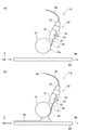
- FIG. 1 (a) and 1 (b) are schematic side views illustrating a part of the coating head according to the first embodiment.
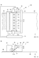
- 2 (a) and 2 (b) are schematic views illustrating the coating head according to the first embodiment.
- FIG. 3 is a schematic view illustrating the coating head according to the first embodiment.
- FIG. 4 is a schematic perspective view illustrating a part of the coating head according to the first embodiment.
- 5 (a) and 5 (b) are schematic side views illustrating a part of the coating head according to the first embodiment.
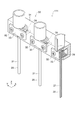
- FIG. 6 is a schematic perspective view illustrating a part of the coating head according to the first embodiment.
- FIG. 7 is a schematic view illustrating the coating head according to the first embodiment.
- FIG. 8 is a schematic perspective view illustrating a part of the coating head according to the first embodiment.
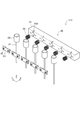
- FIG. 9 is a schematic exploded perspective view illustrating a part of the coating head according to the first embodiment.
- FIG. 10 is a schematic view illustrating a part of the coating head according to the first embodiment.
- FIG. 11 is a schematic view illustrating a part of the coating head according to the first embodiment.
- FIG. 12 is a schematic view illustrating a part of the coating head according to the first embodiment.
- FIG. 13 is a schematic view illustrating the coating device according to the second embodiment.
- FIG. 14 is a schematic view illustrating the coating device according to the second embodiment.
- FIG. 15 is a schematic view illustrating the coating device according to the second embodiment.
- FIG. 1 (a) and 1 (b) are schematic side views illustrating a part of the coating head according to the first embodiment.
- 2 (a) and 2 (b) are schematic views illustrating the coating head according to the first embodiment.
- FIG. 2A is a top view.
- FIG. 2B is a side view. In FIG. 2B, some elements are omitted to make the figure easier to see.
- FIG. 3 is a schematic view illustrating the coating head according to the first embodiment.
- FIG. 3 is a top view of a part of the coating head.
- FIG. 4 is a schematic perspective view illustrating a part of the coating head according to the first embodiment.
- the coating head 110 includes a coating bar 10, a plurality of nozzles 20 (see FIG. 3), a first member 31, and a plurality of first members. It includes two members 32 (see FIG. 3), a plurality of third members 33 (see FIG. 3), a plurality of elastic members 35 (see FIG. 3), and a position control unit 40 (see FIG. 2A).
- the plurality of nozzles 20, the first member 31, the plurality of second members 32, and the plurality of third members 33 are included in the head portion 30 (see FIG. 1A).
- the coating bar 10 can face the member to be coated 80.
- the plurality of nozzles 20 can supply the liquid 84 toward the coating bar 10.
- the plurality of nozzles 20 are, for example, needle nozzles.
- FIG. 1A corresponds to a state in which the liquid 84 is not supplied.
- FIG. 1B corresponds to a state in which the liquid 84 is being supplied.
- a gap is provided between the coating bar 10 and the member to be coated 80.
- FIG. 1B when the liquid 84 is supplied to the coating bar 10, a meniscus is formed between the coating bar 10 and the member to be coated 80. In this way, the coating bar 10 can form a meniscus of the liquid 84 between the coating bar 10 and the member to be coated 80.
- the coating film 85 is formed by the liquid 84 applied to the member 80 to be coated. When the coating film 85 is solidified, the desired film can be obtained.
- the direction from the member to be coated 80 to the coating bar 10 is the Z-axis direction.
- One direction perpendicular to the Z-axis direction is defined as the X-axis direction.
- the direction perpendicular to the Z-axis direction and the X-axis direction is defined as the Y-axis direction.
- the member to be coated 80 moves relative to the coating bar 10 along the moving direction 88.
- the moving direction 88 is, for example, along the X-axis direction.
- the coating bar 10 extends in the Y-axis direction.
- the coating bar 10 is cylindrical.
- the plurality of nozzles 20 extend in a direction inclined with respect to the Z-axis direction toward the coating bar 10.
- one of the plurality of nozzles 20 includes a nozzle portion 21 and a base portion 22.
- the nozzle portion 21 is located between one of the plurality of first recesses 31d and one of the plurality of third members 33.
- the base 22 is not between one of the plurality of first recesses 31d and one of the plurality of third members 33.
- the base 22 is provided above, for example, the first member 31.
- the nozzle portion 21 may be detachable from the base portion 22.
- the supply pipe 25 is connected to the base 22.
- the liquid 84 is supplied to the base 22 via the supply pipe 25. The liquid 84 is discharged from the nozzle portion 21.
- FIG. 3 illustrates the head portion 30.
- the first member 31 includes a plurality of first recesses 31d.
- at least a part of one of the plurality of nozzles 20 is between one of the plurality of first recesses 31d and one of the plurality of third members 33.
- At least a part of one of the plurality of nozzles 20 is, for example, a nozzle portion 21.
- At least a part of one of the plurality of nozzles 20 (for example, the nozzle portion 21) and one of the plurality of third members 33 are fixed to the first member 31 by one of the plurality of second members 32. Will be done.
- the first member 31 is a base to which a plurality of nozzles 20 are attached.
- the plurality of second members 32 are fixing members such as screws, for example.
- the first member 31 is provided with a hole or the like into which a fixing member such as a screw is fitted.
- each of the plurality of third members 33 is provided with a hole through which a fixing member such as a screw passes.
- a fixing member such as a screw passes through holes of a plurality of third members (fixing members) and is fixed to the first member 31.
- One of a plurality of nozzles 20 is provided between the first member 31 and one of the plurality of third members 33.
- One of the plurality of nozzles 20 is fixed to the first member 31 by being sandwiched between the first member 31 and one of the plurality of third members 33.
- the plurality of third members 33 are holding members.
- one of the plurality of elastic members 35 is provided at the first position px1.
- the first position px1 is between one of the plurality of third members 33 and one of the plurality of second members 32.
- the position control unit 40 controls the relative position between the plurality of nozzles 20 and the coating bar 10.
- the position control unit 40 includes the first holding unit 41 and the second holding unit 42, and the first holding unit 41 holds the coating bar 10.
- the second holding portion 42 holds a plurality of nozzles 20.
- the second holding unit 42 holds a plurality of nozzles 20 by holding the first member 31.
- the relative positions between the coating bar 10 and the plurality of nozzles 20 can be controlled.
- the liquid 84 is supplied from the plurality of nozzles 20 toward the coating bar 10. This allows the meniscus to spread evenly over a wide area.
- the plurality of nozzles 20 are stably fixed at positions guided by the plurality of first recesses 31d. As a result, the positions of the tips of the plurality of nozzles 20 can be easily aligned. Since the plurality of nozzles 20 are fixed at positions guided by the plurality of first recesses 31d, the pitches of the plurality of nozzles 20 can be set to a desired state.
- the elastic member 35 By fixing using the elastic member 35, it is possible to suppress fluctuations in the coating state due to vibration of the coating bar 10 or the like. For example, even when the supply pump of the liquid 84 has pulsation, the elastic member 35 can easily reduce the influence of pulsation.
- an appropriate force is applied to the plurality of third members 33.
- the plurality of nozzles 20 are held by the first member 31 and the plurality of third members 33 with an appropriate force.
- a plurality of nozzles 20 can be fixed with appropriate tolerance.
- the amount of the liquid 84 discharged from the plurality of nozzles 20 and adhering to the coating bar 10 can be maintained appropriately.
- a uniform coating film 85 can be formed on the member to be coated 80.
- the thickness uniformity is high.
- the position control unit 40 includes, for example, an actuator. At least one of the first holding portion 41 and the second holding portion 42 may include an actuator. For example, the relative positional relationship between the coating bar 10 and the plurality of nozzles 20 can be set satisfactorily.
- the first holding portion 41 may include, for example, a uniaxial actuator (for example, a Z actuator).
- the second holding portion 42 may include, for example, a multi-axis actuator (for example, an XZ ⁇ actuator).
- the coating head 110 may include the first sensors 51a and 51b.
- the first sensors 51a and 51b detect, for example, the distance between the coating bar 10 and the member to be coated 80.
- the coating head 110 may include a control unit 70.
- the control unit 70 obtains, for example, the detection results of the first sensors 51a and 51b, and controls the position control unit 40 (for example, the first holding unit 41) based on the detection results.
- the control unit 70 appropriately controls the distance between the coating bar 10 and the member to be coated 80.
- the first sensors 51a and 51b include, for example, an optical element.
- the first sensors 51a and 51b may include, for example, a camera.
- the coating head 110 may include the second sensors 52a and 52b.
- the second sensors 52a and 52b detect the stress between the plurality of nozzles 20 and the coating bar 10.
- the control unit 70 obtains, for example, the detection results of the second sensors 51a and 52b, and controls the position control unit 40 (for example, the second holding unit 42) based on the detection results.
- the control unit 70 appropriately controls the relative positions of the coating bar 10 and the plurality of nozzles 20.
- the plurality of elastic members 35 may be provided at a second position or a third position in addition to the first position px1. Examples of these positions will be described later.
- the elastic member 35 includes, for example, a spring.
- the spring includes at least one of a coil spring, a leaf spring, and a disc spring.
- the elastic member 35 may contain a resin such as rubber. When the elastic member 35 includes a spring, it is easy to control the force satisfactorily. When the elastic member 35 includes a coil spring, it is easier to control the force better.
- the plurality of nozzles 20 are in contact with the coating bar 10.
- the positions of the plurality of nozzles 20 with respect to the coating bar 10 are stabilized.
- a stable supply of the liquid 84 becomes possible. Since the plurality of nozzles 20 are in contact with the coating bar 10, the uniformity of the coating film 85 is higher than in the case where the plurality of nozzles 20 are not in contact with the coating bar 10.
- the position control unit 40 (for example, at least one of the first holding unit 41 and the second holding unit 42) causes the plurality of nozzles 20 to be in contact with the coating bar 10 and the plurality of nozzles 20 to be separated from the coating bar 10. It may be possible to form a state in which the nozzle is formed.
- the plurality of nozzles 20 and the coating bar 10 can move relatively in the X-axis direction.
- At least one of the first holding portion 41 and the second holding portion 42 has a stress having at least one of the directions from the coating bar 10 to the plurality of nozzles 20 and the orientation from the plurality of nozzles 20 to the coating bar 10. , It may be possible to add to at least one of the coating bar 10 and the plurality of nozzles 20.
- FIG. 5A and 5 (b) are schematic side views illustrating a part of the coating head according to the first embodiment.
- FIG. 5A shows a state in which the plurality of nozzles 20 are separated from the coating bar 10.
- FIG. 5B shows a state in which the plurality of nozzles 20 are in contact with the coating bar 10.
- the stress generated by at least one of the first holding portion 41 and the second holding portion 42 is applied to at least one of the coating bar 10 and the plurality of nozzles 20.
- at least one of the plurality of nozzles 20 may reversibly bend in response to this stress.
- the plurality of nozzles 20 may have appropriate flexibility.
- the plurality of nozzles 20 may be flexible.
- each (one) of the plurality of nozzles 20 includes the end face 21f in a state where the plurality of nozzles 20 are separated from the coating bar 10.
- the liquid 84 is discharged from the end face 21f.
- the angle ⁇ 1 between the end face 21f and the extending direction Dx in which each (one) of the plurality of nozzles 20 extends is preferably, for example, about 90 degrees. In the embodiment, the angle ⁇ 1 is, for example, 80 degrees or more and 100 degrees or less.
- the length of the nozzle 20 is, for example, 2 cm or more and 10 cm or less.
- the length of the nozzle 20 may be, for example, 3 cm or more and 6 cm or less.
- the inner diameter of the nozzle 20 is 0.15 mm or more and 2 mm or less. When the inner diameter is 0.15 mm or more, the requirement for the pump pressure for supplying the liquid 84 to the nozzle 20 is relaxed. When the inner diameter is 2 mm or less, the pulsation of the liquid 84 is easily suppressed. This makes it easier to obtain a more uniform coating film.
- FIG. 6 is a schematic perspective view illustrating a part of the coating head according to the first embodiment.
- FIG. 6 illustrates the first member 31 and the plurality of nozzles 20.
- the first member 31 and the plurality of nozzles 20 are drawn so as to be separated from each other so that the figure can be easily seen.
- the first member 31 is provided with a plurality of first recesses 31d.
- Each (one) of the plurality of first recesses 31d extends along the direction in which at least a part (for example, the nozzle portion 21) of each (one) of the plurality of nozzles 20 extends. At least a part of the nozzle portion 21 fits into such a first recess 31d. The position of the nozzle portion 21 is stable.
- each (one) of the plurality of first recesses 31d may be curved.
- the cross-sectional shape of the first recess 31d is "U-shaped".
- the cross-sectional shape of the first recess 31d may be "V-shaped”.
- the cross-sectional shape may be rectangular.
- the radius of curvature of the cross-sectional shape of the first recess 31d is, for example, equal to or greater than the radius of curvature of the cross-sectional shape of the outer surface of the nozzle portion 21.
- At least a part of the nozzle portion 21 enters the first recess 31d.
- another portion of the nozzle portion 21 is outside the first recess 31d.
- the length of the portion of the nozzle portion 21 outside the first recess 31d is 1/3 or more and 2/3 or less of the outer diameter of the nozzle portion 21.
- the outer diameter 21d of the nozzle portion 21 is, for example, 0.4 mm or more and 3 mm or less.
- the length 31dL (see FIG. 6) of the first recess 31d is, for example, 1 cm or more and 3 cm or less.
- FIG. 7 is a schematic view illustrating the coating head according to the first embodiment.
- FIG. 7 is a top view of a part of the coating head.
- the second member 32, the third member 33, and the elastic member 35 are omitted.
- a plurality of nozzles 20 may be provided in a part of the plurality of first recesses 31d.
- the pitch of the plurality of nozzles 20 is larger than the pitch of the plurality of first recesses 31d.
- Nozzles 20 are not provided in some of the plurality of first recesses 31d.
- the pitches of the plurality of nozzles 20 may be changed according to the characteristics of the liquid 84. For example, by providing the plurality of first recesses 31d at a small pitch and providing the plurality of nozzles 20 in a part of the plurality of first recesses 31d, the pitches of the plurality of nozzles 20 can be easily changed.
- the cross-sectional shape of the coating bar 10 is arbitrary.
- the cross-sectional shape of the coating bar is, for example, circular, flat circular or polygonal. A part of the cross-sectional shape may be curved, and the other part may be straight.
- the cross-sectional shape of the surface of the coating bar 10 facing the member to be coated 80 may be curved.
- the surface 10s (for example, the side surface) of the coating bar 10 is in contact with the plurality of nozzles 20.
- the surface 10s may be a curved surface.
- the surface 10s may be a flat surface. When the surface 10s is flat, for example, the contact state between the plurality of nozzles 20 and the coating bar 10 tends to be uniform.
- the coating bar 10 includes, for example, at least one selected from the group consisting of stainless steel, aluminum, titanium and glass.
- the coating bar 10 more preferably contains steleste or aluminum. This facilitates the possibility of the coating bar 10.
- the surface of the coating bar 10 is a mirror surface.
- the surface of the coating bar 10 may include fine irregularities. When fine irregularities are provided, for example, high wettability with respect to the liquid 84 can be obtained.
- the maximum height Rz of the unevenness is, for example, 5 ⁇ m or more and 50 ⁇ m or less.
- the arithmetic mean surface roughness Ra of the unevenness is, for example, 1 ⁇ m or more and 10 ⁇ m or less.
- the sandblasting method creates irregularities.
- FIG. 8 is a schematic perspective view illustrating a part of the coating head according to the first embodiment.
- FIG. 9 is a schematic exploded perspective view illustrating a part of the coating head according to the first embodiment.
- FIG. 10 is a schematic view illustrating a part of the coating head according to the first embodiment.
- FIG. 10 is a top view of a part of the coating head. 8 to 10 exemplify the head portion 30 of the coating head 111 according to the embodiment.
- the configuration of the coating head 111 excluding the head portion 30 may be the same as that of the coating head 110.
- an example of the head portion 30 of the coating head 111 will be described.
- the head portion 30 includes a plurality of nozzles 20, a first member 31, a plurality of second members 32, a plurality of third members 33, and a plurality of elastic members 35.
- the first member 31 includes a plurality of first recesses 31d. At least one part of the plurality of nozzles 20 is between one of the plurality of first recesses 31d and one of the plurality of third members 33. At least one of the above-mentioned ones of the plurality of nozzles 20 and the above-mentioned one of the plurality of third members 33 are fixed to the first member 31 by one of the plurality of second members 32.
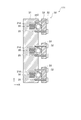
- One of the plurality of elastic members 35 is provided at the second position px2 (see FIG. 10).
- the second position px2 is between at least one of the above-mentioned one of the plurality of first recesses 31d and the above-mentioned one of the plurality of nozzles 20.
- the coating head 111 including such a head portion 30 it is possible to provide a coating head capable of forming a uniform coating film 85.
- FIG. 11 is a schematic view illustrating a part of the coating head according to the first embodiment.
- FIG. 11 is a top view of a part of the coating head.
- FIG. 11 illustrates the head portion 30 of the coating head 112 according to the embodiment.
- the configuration of the coating head 112 excluding the head portion 30 may be the same as that of the coating head 110.
- an example of the head portion 30 of the coating head 112 will be described.
- the head portion 30 includes a plurality of nozzles 20, a first member 31, a plurality of second members 32, a plurality of third members 33, and a plurality of elastic members 35.
- the first member 31 includes a plurality of first recesses 31d.
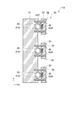
- one of the plurality of elastic members 35 is provided at the third position px3.
- the third position px3 is between at least one part of the plurality of nozzles 20 and one of the plurality of third members 33.
- the coating head 112 including such a head portion 30 it is possible to provide a coating head capable of forming a uniform coating film 85.
- one of the plurality of third members 33 includes a second recess 32d. At least a part of one of the plurality of nozzles 20 is between one of the plurality of first recesses 31d and the second recess 32d. By providing the second recess 32d, the accuracy of the positions of the plurality of nozzles 20 can be further improved.
- the elastic member 35 may be provided at at least one of the above-mentioned first position px1, the above-mentioned second position px2, and the above-mentioned third position px3.
- FIG. 12 is a schematic view illustrating a part of the coating head according to the first embodiment.
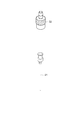
- one of the plurality of nozzles 20 includes a nozzle portion 21 and a base portion 22.
- the nozzle portion 21 and the base portion 22 are removable. This facilitates, for example, cleaning of the nozzle portion 21 and the base portion 22.
- at least one of the nozzle portion 21 and the base portion 22 can be easily replaced.
- the bottom of the base 22 is provided on top of the first member 31. As a result, the tips of the plurality of nozzles 20 can be easily aligned.
- FIG. 13 is a schematic view illustrating the coating device according to the second embodiment.
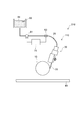
- the coating device 210 according to the embodiment includes a coating head (in this example, the coating head 110) and a supply unit 61 according to the first embodiment.
- the supply unit 61 supplies the liquid 84 to the plurality of nozzles 20.
- the supply unit 61 includes, for example, a pump.
- a tank 65 for storing the liquid 84 is provided.
- the supply unit 61 is connected to the tank 65.
- the supply unit 61 is connected to the nozzle 20 by the supply pipe 25.
- the liquid 84 is supplied from the supply unit 61 to the nozzle 20, and the liquid 84 is supplied from the nozzle 20 toward the coating bar 10.
- the coating head included in the coating device 210 may be any coating head according to the first embodiment.
- a liquid sensor 63 may be provided.
- the liquid sensor 63 detects the supply speed of the liquid 84 to the plurality of nozzles 20.
- the liquid sensor 63 measures the flow rate of the liquid 84 by utilizing, for example, the Doppler effect.
- a supply control unit 75 may be provided.
- the supply control unit 75 controls the supply unit 61 based on the supply speed detected by the liquid sensor 63. This makes it easier to obtain a more uniform coating film.
- FIG. 14 is a schematic view illustrating the coating device according to the second embodiment.
- the coating device 210 may include a member to be coated member holding portion 66.
- the member to be coated 66 holds the member 80 to be coated.
- the member to be coated 66 moves the member to be coated 80 relative to the coating head (in this example, the coating head 110).
- the member to be coated 80 includes a roll-shaped film.
- the member to be coated member holding portion 66 includes a first holding mechanism 66a and a second holding mechanism 66b.
- the first holding mechanism 66a holds the first portion 80a of the roll-shaped film (member to be coated 80).
- the second holding mechanism 66b holds the second portion 80b of the roll-shaped film (member to be coated 80).
- the first holding mechanism 66a and the second holding mechanism 66b are, for example, rollers.
- a meniscus of the liquid 84 is formed between the coating bar 10 and the member 80 to be coated, and the liquid 84 is applied to the member 80 to be coated.
- a coating film 85 made of the liquid 84 is formed on the member 80 to be coated. The coating film 85 is dried and solidified to obtain the desired film.
- the coating device 210 may include a mechanism that can change the position of the coating head 110.
- the member to be coated 80 is preferably a roll-shaped film. High productivity can be applied.
- At least a part of the position of the member to be coated holding portion 66 is higher than the position of the supply portion 61.
- the position of the first holding mechanism 66a is higher than the position of the supply unit 61.
- the moving direction 88 of the member to be coated 80 is preferably the direction from the bottom to the top. This adds gravity to the meniscus. As a result, a uniform coating film 85 can be easily obtained even when the coating film is applied at high speed.
- the moving direction 88 may be inclined with respect to the vertical direction. The angle between the moving direction 88 and the vertical direction is, for example, 30 ° or less.
- the plurality of nozzles 20 supply the liquid 84 to the coating bar 10 from above the coating bar 10. For example, dripping of the liquid 84 can be suppressed.
- a joint may be provided so that the supply pipe 25 and the nozzle 20 can be attached and detached.
- a plurality of supply pipes 25 for supplying the liquid 84 from one tank 65 to the plurality of nozzles 20 are provided. This makes it easier to supply the liquid to the plurality of nozzles 20, for example, with a uniform pressure.
- a cleaning mechanism for cleaning the coating bar 10 may be provided.
- the cleaning mechanism sprays or radiates, for example, a solvent (eg, water).
- the cleaning mechanism may be capable of applying ultrasonic waves, for example.
- a recovery mechanism for recovering excess liquid may be provided.
- FIG. 15 is a schematic view illustrating the coating device according to the second embodiment.
- the supply unit 61 may include a plurality of pumps 61p.
- the number of the plurality of nozzles 20 is an integral multiple of the plurality of pumps 61p. Thereby, the number of pumps 61p can be reduced. It is more preferable that the number of nozzles 20 to which the liquid 84 is supplied from one pump 61p is 2 n (n is an integer).
- the third embodiment relates to a coating method.
- the liquid 84 is applied to the member 80 to be coated by the coating head according to the first embodiment.
- the liquid 84 is applied to the member to be coated 80 by the coating apparatus according to the second embodiment.
- a coating method capable of forming a uniform coating film can be provided.
- the pitch of the plurality of nozzles 20 may be determined based on the viscosity of the liquid 84 and the surface tension of the liquid 84.
- a processing unit that outputs an appropriate pitch from the viscosity and surface tension may be provided.
- a film contained in a solar cell may be formed by the coating head according to the embodiment.
- the member to be coated 80 is a roll-shaped film.
- the member 80 to be coated is a roll-shaped PET film.
- the width of the PET film (length in the Y-axis direction) is 300 mm.
- a light-transmitting conductive film is formed on a roll-shaped film by a roll-to-roll sputtering apparatus.
- the conductive film is an ITO / Ag alloy / ITO laminated film.
- the sheet resistance of the conductive film is about 5 ⁇ / ⁇ .
- the conductive film is patterned into a desired shape by laser irradiation.
- the cross-sectional shape of the coating bar 10 is substantially trapezoidal.
- the bottom of the cross-sectional shape of the coating bar 10 is an arc shape having a curvature of 80 mm.
- the length of the coating bar 10 in the Y-axis direction is 300 mm.
- the coating bar 10 is SUS303.
- the length of the first member 31 in the Y-axis direction is 320 mm.
- the pitch of the plurality of first recesses 31d is 20 mm.
- the cross-sectional shape of the first recess 31d is "V-shaped".
- the length of the plurality of third members 33 in the Y-axis direction is 30 mm.
- the length of the nozzle 20 is about 50 mm.
- the nozzle 20 contains stainless steel.
- the inner diameter of the nozzle 20 is 0.8 mm.
- the nozzle 20 is fixed to the first recess 31d of the first member 31 by the second member 32 by using the third member 33 and the spring (elastic member 35).
- the supply pipe 25 is connected to the base 22 of the nozzle 20.
- the supply pipe 25 is a fluororesin tube.
- the base 22 and the supply pipe 25 are connected by a detachable connecting member.
- the first liquid is a PEDOT / PSS aqueous dispersion.
- the first liquid is one of the liquids 84. From the first liquid, for example, a hole transport layer of a solar cell can be produced.
- the first liquid is supplied from the plurality of nozzles 20 toward the coating bar 10.
- the discharge amount of the first liquid from one of the plurality of nozzles 20 is, for example, 20 ⁇ L / s.
- the moving speed of the member 80 to be coated is about 83 mm / s.
- the coating film 85 with the first liquid is dried in a roll-to-roll compatible hot air drying oven.
- the second liquid is applied onto the above-mentioned coating film 85 (hole transport layer) after drying.
- 8 mg of PTB7 [poly ⁇ 4,8-bis [(2-ethylhexyl) oxy] benzo [1,2-b: 4,5-b'] dithiophene- 2,6-diyl-1t-alt-3-fluoro-2-[(2-ethylhexyl) carbonyl] thieno [3,4-b] thiophene-4,6-diyl ⁇ ] / p-type semiconductor
- PC70BM [6,6] phenyl C71 methyl ester butylate / n-type semiconductor
- the distance between the application bar 10 and the member to be applied 80 is 300 ⁇ m.
- the discharge amount of the second liquid from one of the plurality of nozzles 20 is, for example, 40 ⁇ L / s.
- the moving speed of the member 80 to be coated is about 83 mm / s.
- the coating film 85 with the second liquid is dried in a roll-to-roll compatible hot air drying oven.
- the thickness unevenness of the coating film 85 by the first liquid and the coating film 85 by the second liquid is 5% or less.
- the coating bar 10 contains minute irregularities.
- the maximum height Rz of the unevenness is about 20 ⁇ m.
- the arithmetic mean surface roughness Ra of the unevenness is about 3 ⁇ m.
- the discharge amount of the first liquid from one of the plurality of nozzles 20 is, for example, 25 ⁇ L / s.
- the discharge amount of the first liquid from one of the plurality of nozzles 20 is, for example, 45 ⁇ L / s.
- the thickness unevenness of the coating film 85 by the first liquid and the coating film 85 by the second liquid is 7% or less.
- the elastic member 35 is not provided in the coating head.
- Other conditions in the third experiment are the same as in the first experiment.
- the thickness unevenness of the coating film 85 by the first liquid is 10% or more.
- the unevenness of the thickness of the coating film 85 due to the second liquid is 10% or more.
- the first member 31 is not provided with the first recess 31d in the coating head.
- Other conditions in the fourth experiment are the same as in the first experiment.
- the thickness unevenness of the coating film 85 by the first liquid is 15% or more.
- the unevenness of the thickness of the coating film 85 due to the second liquid is 15% or more.
- the plurality of nozzles 20 cannot uniformly contact the coating bar 10.
- a low-cost solar cell can be obtained by forming a layer contained in the solar cell by coating.
- roll-to-roll coating provides a uniform coating film.
- a meniscus is formed between the coating bar 10 and the member to be coated 80.
- the positions of the plurality of nozzles 20 are determined by using the groove (first recess 31d) as a guide.
- a plurality of nozzles 20 are fixed to the first member 31 by using the elastic member 35.
- the embodiment includes the following configurations (eg, technical proposals).
- a plurality of elastic members one of the plurality of elastic members is provided at at least one of the first position, the second position, and the third position, and the first position is the plurality of third members.
- the second position is between the at least a portion of the one of the plurality of first recesses and the one of the plurality of nozzles.
- the third position is the plurality of elastic members, which are between the at least a part of the one of the plurality of nozzles and the one of the plurality of third members.
- a position control unit that controls the relative position between the plurality of nozzles and the coating bar, Coating head with.
- (Structure 2) The coating head according to configuration 1, wherein the plurality of nozzles are in contact with the coating bar.
- (Structure 3) The coating head according to configuration 1 or 2, wherein the one of the plurality of first recesses extends along a direction in which at least a part of the one of the plurality of nozzles extends.
- (Structure 4) The surface of the coating bar contains irregularities and The coating head according to any one of configurations 1 to 3, wherein the maximum height Rz of the unevenness is 5 ⁇ m or more and 50 ⁇ m or less.
- (Structure 5) The coating head according to any one of configurations 1 to 4, wherein the plurality of elastic members include a spring.
- the one of the plurality of nozzles includes an end face for discharging the liquid.
- the coating head according to any one of configurations 1 to 7, wherein the angle between the end face and the extending direction in which the one of the plurality of nozzles extends is 80 degrees or more and 100 degrees or less.
- the one of the plurality of nozzles includes a nozzle portion and a base portion.
- the nozzle portion is removable from the base portion and is removable.
- the liquid is supplied to the base and The coating head according to any one of configurations 1 to 8, wherein the liquid is discharged from the nozzle portion.
- the nozzle portion is located between the one of the plurality of first recesses and the one of the plurality of third members.
- the coating head according to any one of configurations 1 to 10 wherein the coating bar can form a meniscus of the liquid between the coating bar and the member to be coated.
- the one of the plurality of third members includes a second recess.
- the coating head according to any one of configurations 1 to 11, wherein at least a part of the one of the plurality of nozzles is located between the one of the plurality of first recesses and the second recess. .. (Structure 13)
- the position control unit A first holding portion for holding the coating bar and A second holding unit that holds the plurality of nozzles, Including At least one of the first holding portion and the second holding portion has a stress having at least one of the directions from the coating bar to the plurality of nozzles and the direction from the plurality of nozzles to the coating bar.
- the coating head according to any one of configurations 1 to 12, which can be added to at least one of the coating bar and the plurality of nozzles. (Structure 14) 13.
- the member to be coated includes a roll-shaped film and includes a roll-shaped film.
- the member holding portion to be coated is A first holding mechanism for holding the first portion of the roll-shaped film, and A second holding mechanism for holding the second portion of the roll-shaped film, and 15.
- the supply unit includes a plurality of pumps.
- (Structure 20) A coating method for applying the liquid to the member to be coated by the coating head according to any one of the configurations 1 to 14.
- a coating head, a coating device, and a coating method capable of forming a uniform coating film are provided.
- the present invention has been described above with reference to specific examples. However, the present invention is not limited to these specific examples.
- the present invention is similarly carried out by appropriately selecting from a range known to those skilled in the art. Is included in the scope of the present invention as long as the effect of the above can be obtained.
- 10 ... coating bar 10s ... surface, 20 ... nozzle, 21 ... nozzle part, 21d ... outer diameter, 21f ... end face, 22 ... base, 25 ... supply pipe, 30 ... head part, 31-33 ... 1st to 3rd Member, 31d ... 1st recess, 31dL ... Length, 32d ... 2nd recess, 35 ... Elastic member, 40 ... Position control unit, 41, 42 ... Holding unit, 51a, 51b ... 1st sensor, 52a, 52b ... First 2 sensors, 61 ... Supply unit, 61p ... Pump, 63 ... Liquid sensor, 65 ... Tank, 66 ... Member to be coated, 66a, 66b ...
- 1st and 2nd holding mechanisms 70 ... Control unit, 75 ... Supply control Part, 80 ... member to be coated, 80a, 80b ... first and second parts, 84 ... liquid, 85 ... coating film, 88 ... moving direction, ⁇ 1 ... angle, 110-112 ... coating head, 210 ... coating device, Dx ... Extension direction, px1 to px3 ... 1st to 3rd positions
Landscapes
- Coating Apparatus (AREA)
- Supply And Distribution Of Alternating Current (AREA)
- Control Of Electrical Variables (AREA)
Priority Applications (5)
| Application Number | Priority Date | Filing Date | Title |
|---|---|---|---|
| PCT/JP2020/009946 WO2021181445A1 (ja) | 2020-03-09 | 2020-03-09 | 塗布ヘッド、塗布装置及び塗布方法 |
| JP2021550055A JP7077491B2 (ja) | 2020-03-09 | 2020-03-09 | 塗布ヘッド、塗布装置及び塗布方法 |
| EP20919373.9A EP4119237B1 (en) | 2020-03-09 | 2020-03-09 | Coating head, coating device, and coating method |
| CN202080017045.3A CN113631277B (zh) | 2020-03-09 | 2020-03-09 | 涂布头、涂布装置及涂布方法 |
| US17/445,735 US11707759B2 (en) | 2020-03-09 | 2021-08-24 | Coating head, coating apparatus, and coating method |
Applications Claiming Priority (1)
| Application Number | Priority Date | Filing Date | Title |
|---|---|---|---|
| PCT/JP2020/009946 WO2021181445A1 (ja) | 2020-03-09 | 2020-03-09 | 塗布ヘッド、塗布装置及び塗布方法 |
Related Child Applications (1)
| Application Number | Title | Priority Date | Filing Date |
|---|---|---|---|
| US17/445,735 Continuation US11707759B2 (en) | 2020-03-09 | 2021-08-24 | Coating head, coating apparatus, and coating method |
Publications (1)
| Publication Number | Publication Date |
|---|---|
| WO2021181445A1 true WO2021181445A1 (ja) | 2021-09-16 |
Family
ID=77670485
Family Applications (1)
| Application Number | Title | Priority Date | Filing Date |
|---|---|---|---|
| PCT/JP2020/009946 Ceased WO2021181445A1 (ja) | 2020-03-09 | 2020-03-09 | 塗布ヘッド、塗布装置及び塗布方法 |
Country Status (5)
| Country | Link |
|---|---|
| US (1) | US11707759B2 (https=) |
| EP (1) | EP4119237B1 (https=) |
| JP (1) | JP7077491B2 (https=) |
| CN (1) | CN113631277B (https=) |
| WO (1) | WO2021181445A1 (https=) |
Cited By (5)
| Publication number | Priority date | Publication date | Assignee | Title |
|---|---|---|---|---|
| JPWO2023157285A1 (https=) * | 2022-02-21 | 2023-08-24 | ||
| JPWO2024105718A1 (https=) * | 2022-11-14 | 2024-05-23 | ||
| JPWO2024185086A1 (https=) * | 2023-03-08 | 2024-09-12 | ||
| JPWO2024185092A1 (https=) * | 2023-03-08 | 2024-09-12 | ||
| US12420304B2 (en) | 2021-03-04 | 2025-09-23 | Kabushiki Kaisha Toshiba | Coating apparatus and coating method |
Families Citing this family (1)
| Publication number | Priority date | Publication date | Assignee | Title |
|---|---|---|---|---|
| US12434258B2 (en) * | 2021-09-15 | 2025-10-07 | GE Precision Healthcare LLC | System for high throughput printing of pressure sensitive adhesive |
Citations (6)
| Publication number | Priority date | Publication date | Assignee | Title |
|---|---|---|---|---|
| JPH0919657A (ja) * | 1995-07-07 | 1997-01-21 | Mitsubishi Chem Corp | 塗膜形成方法 |
| JP2006256051A (ja) * | 2005-03-16 | 2006-09-28 | Fuji Xerox Co Ltd | 液滴吐出ヘッドバー、液滴吐出装置、及び、液滴吐出ヘッドバー製造方法 |
| JP2011206715A (ja) * | 2010-03-30 | 2011-10-20 | Dainippon Screen Mfg Co Ltd | 塗布装置 |
| JP2016155113A (ja) * | 2015-02-26 | 2016-09-01 | 株式会社東芝 | 塗布方法および塗布装置 |
| JP2016155114A (ja) * | 2015-02-26 | 2016-09-01 | 株式会社東芝 | 塗布方法および塗布装置 |
| JP2016174992A (ja) | 2015-03-18 | 2016-10-06 | 株式会社東芝 | 塗布方法および塗布装置 |
Family Cites Families (9)
| Publication number | Priority date | Publication date | Assignee | Title |
|---|---|---|---|---|
| US20020121239A1 (en) * | 1996-04-10 | 2002-09-05 | Tonazzi Juan C. Lopez | Devices and methods for applying liquid coatings to substrates |
| DE10061710A1 (de) * | 2000-12-12 | 2002-06-13 | Basf Ag | Verfahren und Vorrichtung zum Aufbringen mindestens zweier unterschiedlicher fließfähiger Medien auf Oberflächen |
| US8733275B2 (en) * | 2005-03-11 | 2014-05-27 | Toray Industries, Inc. | Application apparatus, application method and method for manufacturing web having coating film |
| CN101939114A (zh) * | 2008-02-08 | 2011-01-05 | 中央硝子株式会社 | 涂布液的涂布装置及涂布方法 |
| DE102010038583A1 (de) * | 2010-07-28 | 2012-02-02 | Nordson Corporation | Düsenanordnung zum Abgeben von flüssigem Material |
| JP6239548B2 (ja) * | 2015-03-18 | 2017-11-29 | 株式会社東芝 | 塗布装置及び塗布方法 |
| CN108499756A (zh) * | 2018-03-26 | 2018-09-07 | 佛山汇众森泰科技有限公司 | 一种涂料耐磨喷嘴 |
| CN207592089U (zh) * | 2018-04-03 | 2018-07-10 | 南京箬升机电制造有限公司 | 一种无人机用喷嘴壳体组合 |
| CN108580174B (zh) * | 2018-06-30 | 2024-09-17 | 中国科学院上海硅酸盐研究所 | 一种钙钛矿太阳能电池中钙钛矿吸光层的涂布工艺及装置 |
-
2020
- 2020-03-09 EP EP20919373.9A patent/EP4119237B1/en active Active
- 2020-03-09 WO PCT/JP2020/009946 patent/WO2021181445A1/ja not_active Ceased
- 2020-03-09 JP JP2021550055A patent/JP7077491B2/ja active Active
- 2020-03-09 CN CN202080017045.3A patent/CN113631277B/zh active Active
-
2021
- 2021-08-24 US US17/445,735 patent/US11707759B2/en active Active
Patent Citations (6)
| Publication number | Priority date | Publication date | Assignee | Title |
|---|---|---|---|---|
| JPH0919657A (ja) * | 1995-07-07 | 1997-01-21 | Mitsubishi Chem Corp | 塗膜形成方法 |
| JP2006256051A (ja) * | 2005-03-16 | 2006-09-28 | Fuji Xerox Co Ltd | 液滴吐出ヘッドバー、液滴吐出装置、及び、液滴吐出ヘッドバー製造方法 |
| JP2011206715A (ja) * | 2010-03-30 | 2011-10-20 | Dainippon Screen Mfg Co Ltd | 塗布装置 |
| JP2016155113A (ja) * | 2015-02-26 | 2016-09-01 | 株式会社東芝 | 塗布方法および塗布装置 |
| JP2016155114A (ja) * | 2015-02-26 | 2016-09-01 | 株式会社東芝 | 塗布方法および塗布装置 |
| JP2016174992A (ja) | 2015-03-18 | 2016-10-06 | 株式会社東芝 | 塗布方法および塗布装置 |
Non-Patent Citations (1)
| Title |
|---|
| See also references of EP4119237A4 |
Cited By (12)
| Publication number | Priority date | Publication date | Assignee | Title |
|---|---|---|---|---|
| US12420304B2 (en) | 2021-03-04 | 2025-09-23 | Kabushiki Kaisha Toshiba | Coating apparatus and coating method |
| JPWO2023157285A1 (https=) * | 2022-02-21 | 2023-08-24 | ||
| WO2023157285A1 (ja) * | 2022-02-21 | 2023-08-24 | 株式会社 東芝 | 塗布装置及び塗布方法 |
| JP7560681B2 (ja) | 2022-02-21 | 2024-10-02 | 株式会社東芝 | 塗布装置及び塗布方法 |
| JPWO2024105718A1 (https=) * | 2022-11-14 | 2024-05-23 | ||
| WO2024105718A1 (ja) * | 2022-11-14 | 2024-05-23 | 株式会社 東芝 | 塗布装置、メニスカスヘッドおよび塗布方法 |
| JP7698803B2 (ja) | 2022-11-14 | 2025-06-25 | 株式会社東芝 | 塗布装置、メニスカスヘッドおよび塗布方法 |
| JPWO2024185086A1 (https=) * | 2023-03-08 | 2024-09-12 | ||
| JPWO2024185092A1 (https=) * | 2023-03-08 | 2024-09-12 | ||
| WO2024185092A1 (ja) * | 2023-03-08 | 2024-09-12 | 株式会社 東芝 | 塗布装置および塗布方法 |
| WO2024185086A1 (ja) * | 2023-03-08 | 2024-09-12 | 株式会社 東芝 | 塗布装置および塗布方法 |
| JP7714830B2 (ja) | 2023-03-08 | 2025-07-29 | 株式会社東芝 | 塗布装置および塗布方法 |
Also Published As
| Publication number | Publication date |
|---|---|
| CN113631277A (zh) | 2021-11-09 |
| JP7077491B2 (ja) | 2022-05-30 |
| EP4119237A4 (en) | 2024-01-03 |
| CN113631277B (zh) | 2023-05-02 |
| US20210387222A1 (en) | 2021-12-16 |
| EP4119237A1 (en) | 2023-01-18 |
| US11707759B2 (en) | 2023-07-25 |
| JPWO2021181445A1 (https=) | 2021-09-16 |
| EP4119237B1 (en) | 2025-12-24 |
Similar Documents
| Publication | Publication Date | Title |
|---|---|---|
| JP7077491B2 (ja) | 塗布ヘッド、塗布装置及び塗布方法 | |
| US12233432B2 (en) | Coating apparatus and coating method | |
| US20240399406A1 (en) | Coating device, meniscus head, and coating method | |
| JP7362936B2 (ja) | 塗布装置及び塗布方法 | |
| US20170333936A1 (en) | Segmented or selected-area coating | |
| KR101432361B1 (ko) | 도포 장치 | |
| CN112789120A (zh) | 涂布方法、涂布棒状头及涂布装置 | |
| US20250178015A1 (en) | Coating device and coating method | |
| KR102011913B1 (ko) | 잉크젯 장치 | |
| CN119744203A (zh) | 涂敷头、涂敷装置以及涂敷方法 | |
| KR101087584B1 (ko) | 자기부상을 이용한 원통형 기판용 코팅 장치 | |
| JP7714830B2 (ja) | 塗布装置および塗布方法 | |
| JP7560681B2 (ja) | 塗布装置及び塗布方法 | |
| JP2007044626A (ja) | 塗膜形成装置 | |
| CN118946228A (zh) | 基板对位装置 | |
| JP4056334B2 (ja) | 塗布装置 | |
| JP2026055505A (ja) | 塗工装置 |
Legal Events
| Date | Code | Title | Description |
|---|---|---|---|
| ENP | Entry into the national phase |
Ref document number: 2021550055 Country of ref document: JP Kind code of ref document: A |
|
| 121 | Ep: the epo has been informed by wipo that ep was designated in this application |
Ref document number: 20919373 Country of ref document: EP Kind code of ref document: A1 |
|
| NENP | Non-entry into the national phase |
Ref country code: DE |
|
| ENP | Entry into the national phase |
Ref document number: 2020919373 Country of ref document: EP Effective date: 20221010 |
|
| WWG | Wipo information: grant in national office |
Ref document number: 2020919373 Country of ref document: EP |