WO2021176616A1 - 内視鏡及び内視鏡システム - Google Patents
内視鏡及び内視鏡システム Download PDFInfo
- Publication number
- WO2021176616A1 WO2021176616A1 PCT/JP2020/009256 JP2020009256W WO2021176616A1 WO 2021176616 A1 WO2021176616 A1 WO 2021176616A1 JP 2020009256 W JP2020009256 W JP 2020009256W WO 2021176616 A1 WO2021176616 A1 WO 2021176616A1
- Authority
- WO
- WIPO (PCT)
- Prior art keywords
- endoscope
- built
- optical unit
- magnets
- tip
- Prior art date
- Legal status (The legal status is an assumption and is not a legal conclusion. Google has not performed a legal analysis and makes no representation as to the accuracy of the status listed.)
- Ceased
Links
Images




Classifications
-
- A—HUMAN NECESSITIES
- A61—MEDICAL OR VETERINARY SCIENCE; HYGIENE
- A61B—DIAGNOSIS; SURGERY; IDENTIFICATION
- A61B1/00—Instruments for performing medical examinations of the interior of cavities or tubes of the body by visual or photographical inspection, e.g. endoscopes; Illuminating arrangements therefor
- A61B1/00163—Optical arrangements
- A61B1/00188—Optical arrangements with focusing or zooming features
-
- A—HUMAN NECESSITIES
- A61—MEDICAL OR VETERINARY SCIENCE; HYGIENE
- A61B—DIAGNOSIS; SURGERY; IDENTIFICATION
- A61B1/00—Instruments for performing medical examinations of the interior of cavities or tubes of the body by visual or photographical inspection, e.g. endoscopes; Illuminating arrangements therefor
- A61B1/00064—Constructional details of the endoscope body
- A61B1/00071—Insertion part of the endoscope body
- A61B1/0008—Insertion part of the endoscope body characterised by distal tip features
- A61B1/00096—Optical elements
-
- A—HUMAN NECESSITIES
- A61—MEDICAL OR VETERINARY SCIENCE; HYGIENE
- A61B—DIAGNOSIS; SURGERY; IDENTIFICATION
- A61B1/00—Instruments for performing medical examinations of the interior of cavities or tubes of the body by visual or photographical inspection, e.g. endoscopes; Illuminating arrangements therefor
- A61B1/00002—Operational features of endoscopes
- A61B1/00004—Operational features of endoscopes characterised by electronic signal processing
- A61B1/00009—Operational features of endoscopes characterised by electronic signal processing of image signals during a use of endoscope
-
- A—HUMAN NECESSITIES
- A61—MEDICAL OR VETERINARY SCIENCE; HYGIENE
- A61B—DIAGNOSIS; SURGERY; IDENTIFICATION
- A61B1/00—Instruments for performing medical examinations of the interior of cavities or tubes of the body by visual or photographical inspection, e.g. endoscopes; Illuminating arrangements therefor
- A61B1/00064—Constructional details of the endoscope body
- A61B1/00071—Insertion part of the endoscope body
- A61B1/0008—Insertion part of the endoscope body characterised by distal tip features
- A61B1/00091—Nozzles
-
- A—HUMAN NECESSITIES
- A61—MEDICAL OR VETERINARY SCIENCE; HYGIENE
- A61B—DIAGNOSIS; SURGERY; IDENTIFICATION
- A61B1/00—Instruments for performing medical examinations of the interior of cavities or tubes of the body by visual or photographical inspection, e.g. endoscopes; Illuminating arrangements therefor
- A61B1/012—Instruments for performing medical examinations of the interior of cavities or tubes of the body by visual or photographical inspection, e.g. endoscopes; Illuminating arrangements therefor characterised by internal passages or accessories therefor
- A61B1/015—Control of fluid supply or evacuation
-
- A—HUMAN NECESSITIES
- A61—MEDICAL OR VETERINARY SCIENCE; HYGIENE
- A61B—DIAGNOSIS; SURGERY; IDENTIFICATION
- A61B1/00—Instruments for performing medical examinations of the interior of cavities or tubes of the body by visual or photographical inspection, e.g. endoscopes; Illuminating arrangements therefor
- A61B1/012—Instruments for performing medical examinations of the interior of cavities or tubes of the body by visual or photographical inspection, e.g. endoscopes; Illuminating arrangements therefor characterised by internal passages or accessories therefor
- A61B1/018—Instruments for performing medical examinations of the interior of cavities or tubes of the body by visual or photographical inspection, e.g. endoscopes; Illuminating arrangements therefor characterised by internal passages or accessories therefor for receiving instruments
-
- A—HUMAN NECESSITIES
- A61—MEDICAL OR VETERINARY SCIENCE; HYGIENE
- A61B—DIAGNOSIS; SURGERY; IDENTIFICATION
- A61B1/00—Instruments for performing medical examinations of the interior of cavities or tubes of the body by visual or photographical inspection, e.g. endoscopes; Illuminating arrangements therefor
- A61B1/04—Instruments for performing medical examinations of the interior of cavities or tubes of the body by visual or photographical inspection, e.g. endoscopes; Illuminating arrangements therefor combined with photographic or television appliances
- A61B1/05—Instruments for performing medical examinations of the interior of cavities or tubes of the body by visual or photographical inspection, e.g. endoscopes; Illuminating arrangements therefor combined with photographic or television appliances characterised by the image sensor, e.g. camera, being in the distal end portion
- A61B1/051—Details of CCD assembly
-
- A—HUMAN NECESSITIES
- A61—MEDICAL OR VETERINARY SCIENCE; HYGIENE
- A61B—DIAGNOSIS; SURGERY; IDENTIFICATION
- A61B1/00—Instruments for performing medical examinations of the interior of cavities or tubes of the body by visual or photographical inspection, e.g. endoscopes; Illuminating arrangements therefor
- A61B1/06—Instruments for performing medical examinations of the interior of cavities or tubes of the body by visual or photographical inspection, e.g. endoscopes; Illuminating arrangements therefor with illuminating arrangements
- A61B1/0661—Endoscope light sources
- A61B1/0676—Endoscope light sources at distal tip of an endoscope
-
- A—HUMAN NECESSITIES
- A61—MEDICAL OR VETERINARY SCIENCE; HYGIENE
- A61B—DIAGNOSIS; SURGERY; IDENTIFICATION
- A61B1/00—Instruments for performing medical examinations of the interior of cavities or tubes of the body by visual or photographical inspection, e.g. endoscopes; Illuminating arrangements therefor
- A61B1/06—Instruments for performing medical examinations of the interior of cavities or tubes of the body by visual or photographical inspection, e.g. endoscopes; Illuminating arrangements therefor with illuminating arrangements
- A61B1/07—Instruments for performing medical examinations of the interior of cavities or tubes of the body by visual or photographical inspection, e.g. endoscopes; Illuminating arrangements therefor with illuminating arrangements using light-conductive means, e.g. optical fibres
Definitions
- the present invention relates to an endoscope and an endoscope system that change the optical characteristics of an objective optical system by moving a movable frame using an electromagnetic actuator.
- an endoscope capable of changing the optical characteristics of an objective optical unit provided at the tip portion by moving the moving lens frame forward and backward in the optical axis direction has been proposed and put into practical use. ing.
- Japanese Patent Application Laid-Open No. 2015-114651 describes a tubular fixed portion (fixed frame) and a tubular movable frame arranged inside the fixed frame.
- the provided optical unit is disclosed.
- the arrangement of each magnet, the magnetic field, and the like are adjusted so that the movable frame can be appropriately operated in the objective optical unit alone.
- the tip of the endoscope is required to have a smaller diameter. Therefore, the magnet used in the voice coil motor is preferably small, and the generated magnetic force is also weak. In addition, in order to reduce the diameter of the tip portion, it is necessary to arrange other built-in objects at a position close to the objective optical unit. Some of these internal components are made of magnetic material (metal).
- the magnetic field of the voice coil motor is disturbed.
- Such disturbance of the magnetic field of the voice coil motor may cause the moving lens frame to be offset in an unintended direction, thereby deteriorating the operating performance of the movable frame.
- the disturbance of the magnetic field of the voice coil motor may lower the position detection system of the movable frame. Even in such a case, there is a risk that the operating performance of the movable frame may be deteriorated by making it difficult to control the movable frame to an appropriate position.
- the diameter of the tip portion may be increased.
- the present invention has been made in view of the above circumstances, and provides an endoscope and an endoscope system capable of ensuring the operating performance of a movable frame by an inexpensive configuration without increasing the diameter of the tip portion.
- the purpose is.
- the endoscope according to one aspect of the present invention includes an objective optical unit having an actuator that moves the movable frame forward and backward in the optical axis direction using a plurality of magnets, and a plurality of magnetic materials arranged around the objective optical unit. And an endoscope held in a tip frame constituting the tip of the insertion portion, and at least one of the plurality of built-in objects has at least a part of the plurality of magnets. It is arranged at a position where it intersects with one of the straight lines connecting the pole point of the valley of the specific isomagnetic wire of the magnetic field to be formed and the two bending points sandwiching the valley.
- the endoscope according to another aspect of the present invention includes an objective optical unit having an actuator that moves the movable frame forward and backward in the optical axis direction using a plurality of magnets, and a plurality of magnetic materials arranged around the objective optical unit. And an endoscope held in a tip frame constituting the tip of the insertion portion, and at least one of the plurality of built-in objects has at least a part of the plurality of magnets. It is arranged at a position where it intersects with one of the lines connecting the valleys of the isomagnetic wires having different magnetic flux densities of the magnetic fields to be formed.
- the endoscope system includes the endoscope and an image processing device that converts an image pickup signal imaged by the endoscope into an image signal.
- FIG. 1 is a schematic configuration diagram of an endoscope system.
- the endoscope system 1 shown in FIG. 1 includes an endoscope 2, a control device 3, and a display device 4.
- the endoscope 2 can be inserted into a subject such as a human body, and optically observes a predetermined observation site in the subject.
- the subject into which the endoscope 2 is inserted is not limited to the human body, but may be another living body, or an artificial object such as a machine or a building.
- the endoscope 2 has an insertion unit 5 inserted into the subject, an operation unit 6 connected to the base end side of the insertion unit 5, and a universal cord 7 extending from the operation unit 6. Be prepared.
- the insertion portion 5 includes a tip portion 10, a bendable bending portion 11, and a flexible flexible tube portion 12 in this order from the tip end side to the base end side.
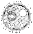
- the tip portion 10 includes an image pickup unit 20 for forming an image of a subject on an image pickup device and a plurality of illumination optical units (for example, three illumination optical units: The first to third illumination optical units 21A to 21C), the treatment tool channel port 22, and the air supply / water supply nozzle 23 are provided.
- illumination optical units for example, three illumination optical units: The first to third illumination optical units 21A to 21C), the treatment tool channel port 22, and the air supply / water supply nozzle 23 are provided.
- a composite cable 25 for transmitting and receiving various signals is connected to the image pickup unit 20 (see FIG. 1). Further, as shown in FIG. 5, the first to third light guide bundles 26A to 26C are connected to the first to third illumination optical system units 21A to 21C, respectively. Further, the treatment tool channel 27 is connected to the treatment tool channel port 22. Further, an air supply / water supply tube 28 is connected to the air supply / water supply nozzle 23.
- These composite cables 25, the first to third light guide bundles 26A to 26C, the treatment tool channel 27, and the air supply / water supply tube 28 are placed inside the operation unit 6 via the curved portion 11 and the flexible pipe portion 12. It has been postponed.
- the light guide bundles 26A to 26C are merged inside the flexible tube portion 12, and then extend to the inside of the operation portion 6 as a bundle of light guide bundles 26.
- the operation unit 6 includes a treatment tool insertion port 6a forming an opening on the base end side of the treatment tool channel 27, an angle operation knob 6b for bending the bending portion 11, and an operation for changing the optical characteristics of the imaging unit 20.
- a zoom lever 6c is provided for this purpose.
- a composite cable 25 extending inside the operation unit 6, a light guide bundle 26, and an air supply / water supply tube 28 are inserted.
- An endoscope connector 8 that is detachably connected to the control device 3 is provided at the base end portion of the universal cord 7.
- the endoscope connector 8 is configured to connect the composite cable 25, the light guide bundle 26, and the air supply / water supply tube 28 to the control device 3.
- the control device 3 has a processor such as a CPU (Central Processing Unit), and controls the entire endoscope system 1.
- the control device 3 includes an image control unit 3a, a light source control unit 3b, and an air supply / water supply control unit 3c.
- the image control unit 3a is electrically connected to the image pickup unit 20 and the operation unit 6 through the composite cable 25.
- the image control unit 3a receives an operation signal for the zoom lever 6c and controls the optical characteristics of the objective optical unit (described later) provided in the image pickup unit 20. Further, the image control unit 3a drives and controls the image pickup element (described later) of the image pickup unit 20 to convert the image pickup signal output from the image pickup unit 20 into an image signal.
- the image converted by the image control unit 3a in this way is displayed by a display device 4 such as a monitor.
- the control device 3 realizes the function as an image processing device by having the image control unit 3a.
- the light source control unit 3b is connected to a light source device (not shown) built in the control device 3. Then, the light source control unit 3b drives and controls the light source device to connect the first to third illumination optical system units 21A to 21C through the light guide bundles 26 (first to third light guide bundles 26A to 26C). Controls the brightness of the supplied illumination light.
- the air supply / water supply control unit 3c is connected to an air supply / water supply device (not shown) built in the control device 3. Then, the air supply / water supply control unit 3c drives or controls the air supply / water supply device to supply air or water to the air supply / water supply nozzle 23 through the air supply / water supply tube 28.
- the tip portion 10 has a tip frame 30 having a hard substantially cylindrical shape made of a metal such as stainless steel.
- a tip frame 30 having a hard substantially cylindrical shape made of a metal such as stainless steel.
- a tip cover 31 forming the tip surface of the tip portion 10 is adhesively fixed to the tip side of the tip frame 30.
- the outer circumference of the tip frame 30 is covered with an outer skin 32. Further, the outer peripheral portion of the outer skin 32 on the tip end side is fixed to the tip frame by the pincushion adhesive portion 33.
- the tip frame 30 is provided with an imaging unit holding hole 30a.
- the image pickup unit 20 is fitted into the image pickup unit holding hole 30a and fixed by a set screw or the like (not shown).
- the tip of the imaging unit 20 is exposed to the outside of the tip cover 31, whereby the observation window 20a is formed at the tip 10.
- Unit holding holes 30bA to 30bC are provided.
- the first to third lighting units 21A to 21C are fitted into the first to third lighting unit holding holes 30bA to 30bC.
- the first to third lighting units 21A to 21C are configured to include a metal illumination lens frame 35 having a substantially cylindrical shape, and a plurality of lenses 36 held inside the illumination lens frame 35. ing.
- the tips of the first to third lighting units 21A to 21C are exposed to the outside of the tip cover 31, whereby the lighting windows 21aA to 21aC are formed on the tip 10.
- a first metal light guide base 37 is attached to the inside of the first to third lighting unit holding holes 30bA to 30bC.
- the tip side of the third light guide bundles 26A to 26C is inserted.
- the first to third light guide bundles 26A to 26C are fixed by pressing the light guide base 37 against the inner wall of the first to third light guide bundles 26A to 26C by the set screw 38 (FIG. 5). reference).
- each of the lighting units 21A to 21C is optically connected to each of the light guide bundles 26A to 26C, and it is possible to irradiate the subject with the illumination light supplied from the control device 3.
- the tip frame 30 is provided with a channel through hole 30c whose tip opens as a treatment tool channel port 22.
- a metal base 40 is inserted into the channel through hole 30c, and the tip end side of the treatment tool channel 27 is connected to the base 40.
- the tip frame 30 is provided with a nozzle insertion hole 30d at a position surrounding the periphery of the image pickup unit 20.
- a metal air supply / water supply nozzle 23 is fitted in the nozzle insertion hole 30d.
- the air supply / water supply nozzle 23 is fixed by an adhesive or the like (not shown) with the ejection port 23a provided at the tip facing the observation window 20a.
- the air supply / water supply tube 28 is connected to the air supply / water supply nozzle 23.
- the air supply / water supply nozzle 23 can inject air and washing water supplied from the control device 3 toward the observation window 20a.
- the image pickup unit 20 includes an image pickup element unit 45 and an objective optical unit 46 connected to the tip end side of the image pickup element unit 45.
- the image sensor unit 45 has an image sensor holding frame 50.
- the front surface side of the solid-state image sensor 51 made of CCD, CMOS, or the like is held by the image sensor holding frame 50 via an optical member 52 such as a cover glass.
- an image sensor substrate 53 on which various control circuits and the like are mounted is electrically connected to the back side of the solid-state image sensor 51.
- various cables branched from the composite cable 25 are electrically connected to the image sensor substrate 53.
- the objective optical unit 46 includes a front group lens frame 55, a rear group lens frame 56, a coil holding frame 57 arranged between the front group lens frame 55 and the rear group lens frame 56, and a coil holding frame 57.
- a moving lens frame 58 as a movable frame slidably arranged inside the lens, a sensor holding frame 59 that integrally holds the front group lens frame 55, the rear group lens frame 56, and the coil holding frame 57. It is configured to have.
- the objective optical unit 46 can change the optical characteristics of the objective optical system by moving the moving lens frame 58 forward and backward in the optical axis O direction using a voice coil motor 60 (see FIG. 7) described later. It is a possible optical unit.
- the front group lens frame 55 is composed of a frame body having a substantially cylindrical shape.
- the front group lens frame 55 is formed so that the outer diameter on the distal end side is larger than the outer diameter on the proximal end side.
- a step portion 55a is formed in the middle of the outer peripheral surface of the front group lens frame 55.
- the step portion 55a is set as a contact surface for positioning with the sensor holding frame 59.
- a front group lens 65 composed of a plurality of fixed lenses is held inside the front group lens frame 55.
- the front lens group 65 constitutes the objective optical system of the objective optical unit 46.
- the rear group lens frame 56 is composed of a frame body having a substantially cylindrical shape.
- the rear group lens frame 56 is formed so that the outer diameter on the distal end side is smaller than the outer diameter on the proximal end side.
- a step portion 56a is formed in the middle of the outer peripheral surface of the rear group lens frame 56.
- the step portion 56a is set as a contact surface for positioning with the coil holding frame 57.
- a rear group lens 66 composed of a plurality of fixed lenses is held inside the rear group lens frame 56.
- the rear lens group 66 constitutes the objective optical system of the objective optical unit 46.
- the coil holding frame 57 is composed of a frame body having a substantially cylindrical shape.
- the coil holding frame 57 is formed with a lightening portion 57a extending in the optical axis O direction at each 90 ° rotation position around the optical axis O (see FIG. 7).
- two coils 67f and 67r constituting the voice coil motor 60 are arranged side by side in the optical axis O direction.
- the moving lens frame 58 is composed of a frame body having a substantially cylindrical shape. Inside the moving lens frame 58, a moving group lens 58a composed of one or more lenses is held. The moving group lens 58a constitutes the objective optical system of the objective optical unit 46.
- a pair of recesses 68f and 68r are provided side by side in the optical axis O direction at each 90 ° rotation position around the optical axis O.
- two magnets 69f and 69r constituting the voice coil motor 60 are held side by side in the optical axis O direction, respectively.
- each magnet 69f, 69r is arranged so as to project from each recess 68f, 68r in the outer diameter direction of the moving lens frame 58. Further, the magnets 69f and 69r are landed so as to have polarity in the thickness direction (that is, the outer diameter direction of the moving lens frame 58).
- the magnets 69f and 69r in the present embodiment are arranged in the recesses 68f and 68r so that, for example, the radial outer side of the moving lens frame 58 is the S pole and the radial inner side of the moving lens frame 58 is the N pole, and the adhesive is used. It is fixed via.
- a key 70 protruding in the outer diameter direction from between the pair of magnets 69f and 69r is provided between one set of the four sets of recesses 68f and 68r provided in the moving lens frame 58. ..
- the key 70 is inserted into any one of the four lightening portions 57a when the moving lens frame 58 is inserted into the coil holding frame 57.
- the rotation of the moving lens frame 58 around the optical axis O is restricted. That is, the moving lens frame 58 is housed inside the coil holding frame 57 in a state in which rotation around the optical axis O is regulated by the key 70 and can be moved in the optical axis O direction.
- the sensor holding frame 59 is composed of a frame body having a substantially cylindrical shape.
- An inward flange 59a is provided on the inner circumference of the sensor holding frame 59 on the tip end side.
- a sensor holding groove 75 is formed on one side of the outer peripheral portion of the sensor holding frame 59.
- a through hole 75a that penetrates the inside and outside of the sensor holding frame 59 is provided in a part of the tip side of the sensor holding groove 75.
- the sensor board 76 is arranged inside the sensor holding groove 75.
- the sensor substrate 76 is provided with a Hall element 77 for detecting a magnetic field on a surface facing the through hole 75a. Further, various cables 25a branched from the composite cable 25 are connected to the sensor board 76. Further, the sensor holding groove 75 is provided with an urging plate 78 made of a metal plate on the outer diameter side of the sensor substrate 76.
- the sensor holding groove 75 in which the sensor substrate 76 and the urging plate 78 are housed in this way is closed by the lid 79.
- the front group lens frame 55 is held on the tip side of such a sensor holding frame 59. Specifically, the front group lens frame 55 is fixed to the sensor holding frame 59 by adhesion or the like with the proximal end side inserted inside the sensor holding frame 59. At that time, the stepped portion 55a of the front group lens frame 55 is brought into contact with the tip surface of the inward flange 59a of the sensor holding frame 59 via an adhesive or the like (not shown). As a result, the front group lens frame 55 is positioned in the optical axis O direction with respect to the sensor holding frame 59.
- the coil holding frame 57 is held inside the sensor holding frame 59. Specifically, the coil holding frame 57 is fixed by adhesion or the like in a state where the tip surface is in contact with the base end surface of the inward flange 59a of the sensor holding frame 59.
- one set of magnets 69f, 69r out of a plurality of sets (4 sets in this embodiment) of magnets 69f, 69r on the moving lens frame 58 housed therein is the Hall element 75.
- the position around the optical axis O is made so as to face the optical axis O.
- the Hall element 75 can detect the position of the moving lens frame 58 in the optical axis O direction from the change in the magnetic field received from the pair of magnets 69f and 69r.
- the Hall element 75 by attracting the pair of magnets 69f and 69r to the urging plate 78 side, the backlash of the moving lens frame 58 inside the coil holding frame 57 is suppressed. As a result, stable sliding performance of the moving lens frame 58 and stable optical characteristics of the objective optical system are realized.
- the rear group lens frame 56 is held at a position closer to the proximal end side than the coil holding frame 57. Specifically, the rear group lens frame 56 is fixed by an adhesive or the like with the tip end side inserted inside the coil holding frame 57 and the proximal end side inserted inside the sensor holding frame 59. ing. At this time, the rear group lens frame 56 is positioned in the optical axis O direction with respect to the coil holding frame 57 by abutting the step portion on the base end surface of the coil holding frame 57.
- the tip end side of the image sensor holding frame 50 is connected to the base end side of the rear group lens frame 56 held by the sensor holding frame 59 in this way.
- the solid-state image sensor 51 is imaged with an image of the subject through the objective optical system of the objective optical unit 46.
- the image control unit 3a of the control device 3 responds to the operating state of the zoom lever 6c.
- Energization control is performed on the coils 67f and 67r.
- the magnets 69f and 69r move the moving lens frame 58 in the optical axis O direction.
- the Hall element 77 detects a change in the magnetic field due to the movement of the magnets 69f and 69r in the optical axis O direction, and outputs the change in the detected magnetic field as a feedback signal to the image control unit 3a.
- the energization of the coils 67f and 67r is feedback-controlled, and the moving lens frame 58 is controlled to a position on the optical axis O according to the operating state of the zoom lever 6c.
- the objective optical unit 46 of the imaging unit 20 forms a magnetic field around the objective optical unit 46 by four sets of magnets 69f and 69r.
- the magnetic field isomagnetic wire shown in FIG. 6 indicates the distribution of the magnetic field of the objective optical unit 46 alone before the objective optical unit 46 is incorporated into the tip frame 30.
- the various built-in objects arranged at the tip portion 10 have a small influence on the magnetic fields formed by the magnets 69f and 69r. Moreover, it is arranged at a position close to the image pickup unit 20.
- various internal objects made of a magnetic material do not generally enter the inside of a specific isomagnetic wire 80 (for example, 100 (mT) in this embodiment). It is arranged as a guide.
- the specific isomagnetic wire 80 is a lower limit value of the isomagnetic wire that is considered to affect the operating performance of the voice coil motor 60. This lower limit value is appropriately determined based on an experiment, a simulation, or the like according to the type of the objective optical system unit 46 or the like. Even if an internal object has entered the inside of the specific isomagnetic wire 80, it can be tolerated as long as the amount of entry is so small that it does not affect the magnetic field.
- At least one of the various built-in objects has at least a part of a valley of isomagnetic wires having different magnetic flux densities of magnetic fields. It is desirable that a part is arranged on the lines connecting the poles (first to fourth lines 83a to 83d).
- at least one of the various internal components is a straight line (first to eighth) connecting the poles 81a to 81d of the valley of the specific isomagnetic wire 80 and the two inflection points 82a to 82h sandwiching each valley. It is desirable that it is arranged at a position intersecting at least one of the straight lines 84a to 84g).
- the pole point of the valley of each isomagnetic wire means the pole point of the portion of the isomagnetic wire having a protruding shape toward between the adjacent magnets 69f and 69r.
- the first to fourth lines 83a to 83d connecting the poles of the valleys of the isomagnetic wires may be an approximate straight line or a spline curve. Since four sets of magnets 69f and 69r are arranged on the outer circumference of the moving lens frame 58 of the present embodiment, valleys of each isometric wire are formed at four locations. Therefore, the first to fourth lines 83a to 83d connecting the valleys of the isomagnetic wires are set around the objective optical unit 46. Further, first to eighth straight lines 84a to 84h connecting the valley of the specific isomagnetic wire 80 and each inflection point are set.
- the first illumination optical unit 21A is arranged at a position intersecting the first line 83a. Further, the first illumination optical unit 21A is at a position where at least a part intersects the first straight line 84a, and most of the pole points (for example, more than half of the cross-sectional area) are the same pole points (pole points). It is arranged so as to be located in the area sandwiched between the two straight lines defined by 81a). By satisfying these conditions, the first illumination optical unit 21A is arranged along the valley of the specific isomagnetic wire 80.
- the illumination lens frame 35, the light guide base 37, and the set screw 38 which are various parts (built-in objects) made of a magnetic material related to the first illumination optical unit 21A, are generally specified and the like. It is not arranged inside the magnetic wire 80, but is arranged in a state of being close to the objective optical unit 46 (imaging unit 20).
- the amount (cross-sectional area) of the illumination lens frame 35 and the light guide base 37 entering the inside of the specific isomagnetic wire 80 is so small that it does not significantly affect the magnetic field.
- the area Sa in which the internal component made of a magnetic material enters the inside of the specific isomagnetic wire 80 is such that the evaluation value E shown in the following equation (1) is the threshold value Eth of the evaluation value in the entire area in the optical axis O direction. It is desirable that it is less than.
- E (Sa / S) ⁇ P ... (1)
- S indicates the cross-sectional area of the built-in material made of a magnetic material
- P indicates the magnetic permeability of the built-in material made of a magnetic material.
- the threshold value Eth is obtained in advance based on experiments, simulations, and the like.
- At least a part of the second illumination optical unit 21B is arranged at a position where it intersects the second line 83b. By satisfying this condition, the second illumination optical unit 21B is arranged along the valley of the specific isomagnetic wire 80.
- the illumination lens frame 35, the light guide base 37, and the set screw 38 which are various parts (built-in objects) made of magnetic materials related to the second illumination optical unit 21B, have a specific isomagnetism. It is not arranged inside the line 80, but is arranged in a state of being close to the objective optical unit 46 (imaging unit 20).
- At least a part of the third illumination optical unit 21C is arranged at a position where it intersects the third line 83c. By satisfying this condition, the third illumination optical unit 21C is arranged along the valley of the specific isomagnetic wire 80.
- the illumination lens frame 35, the light guide base 37, and the set screw 38 which are various parts (built-in objects) made of a magnetic material related to the third illumination optical unit 21C, have a specific isomagnetism. It is not arranged inside the line 80, but is arranged in a state of being close to the objective optical unit 46 (imaging unit 20).
- the air supply / water supply nozzle 23 is at least a part at a position where at least a part intersects the second straight line 84b, and most of the position is defined by the same pole point (pole point 81a). It is arranged so as to be located in the area sandwiched between the two straight lines. By satisfying these conditions, the air supply / water supply nozzle 23 is arranged along the valley of the specific isomagnetic wire 80.
- the treatment tool channel port 22 is separated from the objective optical unit 46 in terms of layout. Therefore, it is not particularly necessary to satisfy the above conditions, but when it is necessary to arrange them in the vicinity of the objective optical system unit 46, at least a part thereof intersects with the first to fourth straight lines 84a to 84d. It is desirable that it is located in.
- an objective optical unit having a voice coil motor 60 that moves the moving lens frame 58 forward and backward in the optical axis O direction by using a plurality of magnets 69f and 69r arranged around the moving lens frame 58.
- At least one of them, at least a part of them, is any one of the first to fourth lines 83a to 83d connecting the poles of the valleys of the isomagnetic wires having different magnetic flux densities of the magnetic fields formed by the plurality of magnets 69f and 69r. Since it is arranged at a position where it intersects with one, the operating performance of the moving lens frame 58 can be ensured by an inexpensive configuration without increasing the diameter of the tip portion 10.
- At least one of the plurality of built-in objects is arranged at a position where at least a part thereof intersects with any one of the first to fourth lines 83a to 83d connecting the poles of the valleys of the isomagnetic wires.
- the built-in object can be efficiently arranged along the valley of the specific isomagnetic wire 80. Therefore, the built-in object can be arranged in the vicinity of the objective optical unit 46 while suppressing the influence of the built-in object on the magnetic field, and the diameter increase of the tip portion 10 can be suppressed.
- the arrangement of the magnets 69f and 69r of the voice coil motor 60 provided in the objective optical unit 46 and the magnetic field are adjusted according to the type of the endoscope 2 and the like. There is no need to change the design. Therefore, the operating performance of the moving lens frame 58 can be ensured by the inexpensive configuration.
- At least one of the plurality of built-in objects is connected to the pole points 81a to 81d of the valley of the specific isomagnetic wire 80 and the two inflection points 82a to 82h sandwiching the valley, respectively.
- the configuration in which all three illumination optical units 21A to 21C are arranged at positions intersecting with any of the first to fourth lines 83a to 83d has been described. Not limited to this, depending on the layout on the tip portion 10, it is possible to arrange the illumination optical unit 1 or 2 at a position intersecting with any of the first to fourth lines 83a to 83d.
- the number of illumination optical units arranged at the tip portion 10 is not limited to three, and may be one or two illumination optical units, and four or more illumination optical units. You may.
- the illumination optical unit is arranged at a position intersecting with any of the first to fourth lines 83a to 83d. It is also possible to arrange other built-in objects such as 23 at a position where they intersect with any of the first to fourth lines 83a to 83d.
- the number of magnets constituting the voice coil motor 60 is not limited to the above-described embodiment.
Landscapes
- Health & Medical Sciences (AREA)
- Life Sciences & Earth Sciences (AREA)
- Surgery (AREA)
- Engineering & Computer Science (AREA)
- Biomedical Technology (AREA)
- Molecular Biology (AREA)
- Pathology (AREA)
- Radiology & Medical Imaging (AREA)
- Nuclear Medicine, Radiotherapy & Molecular Imaging (AREA)
- Biophysics (AREA)
- Physics & Mathematics (AREA)
- Heart & Thoracic Surgery (AREA)
- Medical Informatics (AREA)
- Optics & Photonics (AREA)
- Animal Behavior & Ethology (AREA)
- General Health & Medical Sciences (AREA)
- Public Health (AREA)
- Veterinary Medicine (AREA)
- Signal Processing (AREA)
- Endoscopes (AREA)
- Instruments For Viewing The Inside Of Hollow Bodies (AREA)
Priority Applications (5)
| Application Number | Priority Date | Filing Date | Title |
|---|---|---|---|
| CN202080097951.9A CN115209776B (zh) | 2020-03-04 | 2020-03-04 | 内窥镜及内窥镜系统 |
| JP2022504857A JPWO2021176616A1 (https=) | 2020-03-04 | 2020-03-04 | |
| PCT/JP2020/009256 WO2021176616A1 (ja) | 2020-03-04 | 2020-03-04 | 内視鏡及び内視鏡システム |
| US17/897,610 US12402779B2 (en) | 2020-03-04 | 2022-08-29 | Endoscope and endoscope system |
| US19/293,267 US20250359731A1 (en) | 2020-03-04 | 2025-08-07 | Endoscope and endoscope system |
Applications Claiming Priority (1)
| Application Number | Priority Date | Filing Date | Title |
|---|---|---|---|
| PCT/JP2020/009256 WO2021176616A1 (ja) | 2020-03-04 | 2020-03-04 | 内視鏡及び内視鏡システム |
Related Child Applications (1)
| Application Number | Title | Priority Date | Filing Date |
|---|---|---|---|
| US17/897,610 Continuation US12402779B2 (en) | 2020-03-04 | 2022-08-29 | Endoscope and endoscope system |
Publications (1)
| Publication Number | Publication Date |
|---|---|
| WO2021176616A1 true WO2021176616A1 (ja) | 2021-09-10 |
Family
ID=77613241
Family Applications (1)
| Application Number | Title | Priority Date | Filing Date |
|---|---|---|---|
| PCT/JP2020/009256 Ceased WO2021176616A1 (ja) | 2020-03-04 | 2020-03-04 | 内視鏡及び内視鏡システム |
Country Status (4)
| Country | Link |
|---|---|
| US (2) | US12402779B2 (https=) |
| JP (1) | JPWO2021176616A1 (https=) |
| CN (1) | CN115209776B (https=) |
| WO (1) | WO2021176616A1 (https=) |
Citations (6)
| Publication number | Priority date | Publication date | Assignee | Title |
|---|---|---|---|---|
| JPH0351032A (ja) * | 1989-07-20 | 1991-03-05 | Asahi Optical Co Ltd | 内視鏡の先端部 |
| JPH0654799A (ja) * | 1992-08-07 | 1994-03-01 | Fuji Photo Optical Co Ltd | 電子内視鏡先端部構造 |
| JP2000051141A (ja) * | 1998-08-10 | 2000-02-22 | Olympus Optical Co Ltd | 内視鏡 |
| JP2000135198A (ja) * | 1998-10-30 | 2000-05-16 | Olympus Optical Co Ltd | 内視鏡形状検出装置 |
| JP2015112336A (ja) * | 2013-12-12 | 2015-06-22 | オリンパスメディカルシステムズ株式会社 | 内視鏡システム |
| WO2016166855A1 (ja) * | 2015-04-15 | 2016-10-20 | オリンパス株式会社 | 光学ユニット及び内視鏡 |
Family Cites Families (11)
| Publication number | Priority date | Publication date | Assignee | Title |
|---|---|---|---|---|
| JP2001117185A (ja) * | 1999-10-21 | 2001-04-27 | Toshiba Corp | 立体カメラ装置とそれを用いた内視鏡 |
| WO2006095336A2 (en) * | 2005-03-08 | 2006-09-14 | Truphatek International Ltd | Handheld portable medical viewing assembly for displaying medical images during endotracheal intubation, and intubation stylet for use therewith |
| JP2009142440A (ja) | 2007-12-13 | 2009-07-02 | Fujifilm Corp | 内視鏡装置 |
| JP6180405B2 (ja) * | 2011-05-03 | 2017-08-16 | エンドーシー コーポレイションEndosee Corporation | ヒステロスコピー及び子宮内膜生検用の方法及び装置 |
| JP6618668B2 (ja) | 2013-12-16 | 2019-12-11 | オリンパス株式会社 | 駆動ユニット、光学ユニット、撮像装置及び内視鏡 |
| CN105611865B (zh) * | 2013-12-18 | 2018-06-19 | 奥林巴斯株式会社 | 内窥镜系统 |
| DE102014204784A1 (de) * | 2014-03-14 | 2015-09-17 | Olympus Winter & Ibe Gmbh | Endoskop mit distaler elektrischer Durchführung und Verfahren zur Montage eines Endoskops |
| DE112014006987B4 (de) * | 2014-12-18 | 2018-12-20 | Olympus Corporation | Optische Einheit und Endoskop |
| WO2016194128A1 (ja) * | 2015-06-02 | 2016-12-08 | オリンパス株式会社 | 光学ユニット及び内視鏡 |
| WO2017209754A1 (en) * | 2016-06-02 | 2017-12-07 | GYRUS ACMI, INC. (d/b/a OLYMPUS SURGICAL TECHNOLOGIES AMERICA) | Endoscope working channel protection |
| JP6849567B2 (ja) * | 2017-09-28 | 2021-03-24 | 富士フイルム株式会社 | 内視鏡 |
-
2020
- 2020-03-04 CN CN202080097951.9A patent/CN115209776B/zh active Active
- 2020-03-04 WO PCT/JP2020/009256 patent/WO2021176616A1/ja not_active Ceased
- 2020-03-04 JP JP2022504857A patent/JPWO2021176616A1/ja active Pending
-
2022
- 2022-08-29 US US17/897,610 patent/US12402779B2/en active Active
-
2025
- 2025-08-07 US US19/293,267 patent/US20250359731A1/en active Pending
Patent Citations (6)
| Publication number | Priority date | Publication date | Assignee | Title |
|---|---|---|---|---|
| JPH0351032A (ja) * | 1989-07-20 | 1991-03-05 | Asahi Optical Co Ltd | 内視鏡の先端部 |
| JPH0654799A (ja) * | 1992-08-07 | 1994-03-01 | Fuji Photo Optical Co Ltd | 電子内視鏡先端部構造 |
| JP2000051141A (ja) * | 1998-08-10 | 2000-02-22 | Olympus Optical Co Ltd | 内視鏡 |
| JP2000135198A (ja) * | 1998-10-30 | 2000-05-16 | Olympus Optical Co Ltd | 内視鏡形状検出装置 |
| JP2015112336A (ja) * | 2013-12-12 | 2015-06-22 | オリンパスメディカルシステムズ株式会社 | 内視鏡システム |
| WO2016166855A1 (ja) * | 2015-04-15 | 2016-10-20 | オリンパス株式会社 | 光学ユニット及び内視鏡 |
Also Published As
| Publication number | Publication date |
|---|---|
| CN115209776B (zh) | 2026-03-20 |
| US20250359731A1 (en) | 2025-11-27 |
| JPWO2021176616A1 (https=) | 2021-09-10 |
| US20220409022A1 (en) | 2022-12-29 |
| US12402779B2 (en) | 2025-09-02 |
| CN115209776A (zh) | 2022-10-18 |
Similar Documents
| Publication | Publication Date | Title |
|---|---|---|
| US6641530B2 (en) | Endoscope with objective lens drive mechanism | |
| US6409658B1 (en) | Endoscope with objective lens drive mechanism | |
| US8936546B2 (en) | Endoscopic image pickup unit | |
| JP5178101B2 (ja) | 内視鏡 | |
| EP2478822A1 (en) | Endoscope | |
| WO2008026445A1 (fr) | Capuchon de tête pour endoscope et endoscope avec capuchon | |
| WO2014192386A1 (ja) | 内視鏡 | |
| US20190059709A1 (en) | Insert tube and endoscope using the same | |
| JP6843996B2 (ja) | 内視鏡及び撮像ユニット | |
| EP2505120B1 (en) | Endoscope and lighting optical device therefor | |
| JP6465447B2 (ja) | 内視鏡の製造方法 | |
| JPH1014860A (ja) | 内視鏡 | |
| WO2021176616A1 (ja) | 内視鏡及び内視鏡システム | |
| CN112312820B (zh) | 内窥镜 | |
| JP2018120005A (ja) | 対物レンズユニット | |
| WO2016035393A1 (ja) | 内視鏡 | |
| WO2012017861A1 (ja) | 内視鏡 | |
| US20180000325A1 (en) | Endoscope system | |
| TWI722644B (zh) | 診察鏡用引導機構 | |
| WO2020170312A1 (ja) | 内視鏡 | |
| JP4596137B2 (ja) | 内視鏡 | |
| WO2020246030A1 (ja) | ステレオ撮像装置及び内視鏡 | |
| JP6465438B2 (ja) | 撮像ユニット及び内視鏡 | |
| JP2008110061A (ja) | 内視鏡 | |
| WO2020031378A1 (ja) | 内視鏡 |
Legal Events
| Date | Code | Title | Description |
|---|---|---|---|
| 121 | Ep: the epo has been informed by wipo that ep was designated in this application |
Ref document number: 20922947 Country of ref document: EP Kind code of ref document: A1 |
|
| ENP | Entry into the national phase |
Ref document number: 2022504857 Country of ref document: JP Kind code of ref document: A |
|
| NENP | Non-entry into the national phase |
Ref country code: DE |
|
| 122 | Ep: pct application non-entry in european phase |
Ref document number: 20922947 Country of ref document: EP Kind code of ref document: A1 |