WO2021172027A1 - プログラム、情報処理方法、及び情報処理装置 - Google Patents
プログラム、情報処理方法、及び情報処理装置 Download PDFInfo
- Publication number
- WO2021172027A1 WO2021172027A1 PCT/JP2021/005081 JP2021005081W WO2021172027A1 WO 2021172027 A1 WO2021172027 A1 WO 2021172027A1 JP 2021005081 W JP2021005081 W JP 2021005081W WO 2021172027 A1 WO2021172027 A1 WO 2021172027A1
- Authority
- WO
- WIPO (PCT)
- Prior art keywords
- user
- content
- hmd
- image
- virtual space
- Prior art date
- Legal status (The legal status is an assumption and is not a legal conclusion. Google has not performed a legal analysis and makes no representation as to the accuracy of the status listed.)
- Ceased
Links
Images


Classifications
-
- G—PHYSICS
- G06—COMPUTING OR CALCULATING; COUNTING
- G06F—ELECTRIC DIGITAL DATA PROCESSING
- G06F13/00—Interconnection of, or transfer of information or other signals between, memories, input/output devices or central processing units
-
- G—PHYSICS
- G06—COMPUTING OR CALCULATING; COUNTING
- G06F—ELECTRIC DIGITAL DATA PROCESSING
- G06F3/00—Input arrangements for transferring data to be processed into a form capable of being handled by the computer; Output arrangements for transferring data from processing unit to output unit, e.g. interface arrangements
- G06F3/01—Input arrangements or combined input and output arrangements for interaction between user and computer
- G06F3/048—Interaction techniques based on graphical user interfaces [GUI]
- G06F3/0481—Interaction techniques based on graphical user interfaces [GUI] based on specific properties of the displayed interaction object or a metaphor-based environment, e.g. interaction with desktop elements like windows or icons, or assisted by a cursor's changing behaviour or appearance
Definitions
- the present invention relates to a program, an information processing method, and an information processing device.
- Patent Document 1 a virtual space that is VR content is provided to a terminal device such as a head-mounted display, and a URL (Uniform Resource Locator) address corresponds to a main content display area or a sub-content display area in the virtual space. It is stated that the prescribed content is provided based on the access from the web page.
- the virtual space provided by the method of Patent Document 1 is VR content as a whole, but the main content itself is displayed in a plane in a limited area (for example, a browser window arranged on the virtual space).
- the main content itself can be used as VR content (for example, when it can be used as 360-degree content using a web browser), it is desired to switch the display mode so that the main content itself is displayed as VR content.
- the main content is displayed in a flat area as in Patent Document 1, there is a problem that it is difficult for the user to notice that the main content itself can be used as VR content.
- a similar problem may occur when, for example, content that can be used as so-called XR content such as AR (Augmented Reality) content or MR (Mixed Reality) content is used by using a web browser.
- One aspect of the present disclosure is a program, information processing method, and information processing that make it easy for the user to recognize that the content can be used as XR content when the content that can be used as XR content is used by using a web browser.
- the purpose is to provide the device.
- a program that is executed on a computer equipped with a processor, wherein the program is attached to the processor. Steps to define a virtual space that contains a browser window, A step of providing web content on the browser window based on access to a URL (Uniform Resource Locator) address, and When the web content can be displayed as XR content, the web content can be used as the XR content in a predetermined first period of the period during which the web content is provided on the browser window.
- URL Uniform Resource Locator
- a program that makes it easy for the user to recognize that the content can be used as XR content is provided. Can be done.
- FIG. 1 It is a figure which shows the outline of the structure of the HMD system according to a certain embodiment. It is a block diagram which shows an example of the hardware composition of the computer according to a certain embodiment. It is a figure which conceptually represents the uvw field-of-view coordinate system set in the HMD according to a certain embodiment. It is a figure that conceptually represents one aspect of expressing a virtual space according to a certain embodiment. It is a figure which showed the head of the user who wears an HMD according to a certain embodiment from the top. It is a figure which shows the YZ cross section which looked at the visual field area from the X direction in a virtual space.
- FIG. 5 is a sequence chart representing a portion of the processing performed in an HMD set according to an embodiment. It is a schematic diagram which shows the situation that each HMD provides a virtual space to a user in a network.
- FIG. 6 is a block diagram showing a detailed configuration of a computer module according to an embodiment. It is a flowchart which shows an example of the operation processing executed in the computer which follows a certain embodiment. It is a schematic diagram which shows an example of the virtual space according to a certain embodiment. It is a schematic diagram which shows the XZ cross section which looked at the virtual space shown in FIG. 16 from the Y-axis direction. It is a schematic diagram which shows an example of the display content of the browser window in the 1st period according to a certain embodiment.
- FIG. 1 is a diagram showing an outline of the configuration of the HMD system 100 according to the present embodiment.
- the HMD system 100 is provided as a home system or a business system.
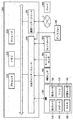
- the HMD system 100 includes a server 600, HMD sets 110A, 110B, 110C, 110D, an external device 700, and a network 2.
- Each of the HMD sets 110A, 110B, 110C, and 110D is configured to be able to communicate with the server 600 and the external device 700 via the network 2.
- the HMD set 110A, 110B, 110C, 110D are collectively referred to as the HMD set 110.
- the number of HMD sets 110 constituting the HMD system 100 is not limited to four, and may be three or less or five or more.
- the HMD set 110 includes an HMD 120, a computer 200, an HMD sensor 410, a display 430, and a controller 300.
- the HMD 120 includes a monitor 130, a gaze sensor 140, a first camera 150, a second camera 160, a microphone 170, and a speaker 180.
- the controller 300 may include a motion sensor 420.
- the computer 200 can connect to the Internet or other network 2 and communicate with the server 600 or other computer connected to the network 2. Examples of other computers include computers of other HMD sets 110 and external devices 700.
- the HMD 120 may include a sensor 190 instead of the HMD sensor 410.
- the HMD 120 may be worn on the head of the user 5 and provide the user 5 with a virtual space during operation. More specifically, the HMD 120 displays an image for the right eye and an image for the left eye on the monitor 130, respectively. When each eye of the user 5 visually recognizes the respective image, the user 5 can recognize the image as a three-dimensional image based on the parallax of both eyes.
- the HMD 120 may include either a so-called head-mounted display having a monitor and a head-mounted device to which a smartphone or other terminal having a monitor can be attached.
- the monitor 130 is realized as, for example, a non-transparent display device.
- the monitor 130 is arranged in the body of the HMD 120 so as to be located in front of both eyes of the user 5. Therefore, the user 5 can immerse himself in the virtual space when he / she visually recognizes the three-dimensional image displayed on the monitor 130.
- the virtual space includes, for example, a background, an object that the user 5 can manipulate, and an image of a menu that the user 5 can select.
- the monitor 130 can be realized as a liquid crystal monitor or an organic EL (ElectroLuminescence) monitor included in a so-called smartphone or other information display terminal.
- the monitor 130 can be realized as a transmissive display device.
- the HMD 120 may be an open type such as a glasses type rather than a closed type that covers the eyes of the user 5 as shown in FIG.
- the transmissive monitor 130 may be temporarily configured as a non-transparent display device by adjusting its transmittance.
- the monitor 130 may include a configuration in which a part of the image constituting the virtual space and the real space are displayed at the same time.
- the monitor 130 may display an image of the real space taken by the camera mounted on the HMD 120, or may make the real space visible by setting a part of the transmittance to be high.
- the monitor 130 may include a sub-monitor for displaying an image for the right eye and a sub-monitor for displaying an image for the left eye.
- the monitor 130 may be configured to display the image for the right eye and the image for the left eye as a unit.
- the monitor 130 includes a high speed shutter. The high-speed shutter operates so that the image for the right eye and the image for the left eye can be alternately displayed so that the image is recognized by only one of the eyes.
- the HMD 120 includes a plurality of light sources (not shown). Each light source is realized by, for example, an LED (Light Emitting Diode) that emits infrared rays.
- the HMD sensor 410 has a position tracking function for detecting the movement of the HMD 120. More specifically, the HMD sensor 410 reads a plurality of infrared rays emitted by the HMD 120 and detects the position and inclination of the HMD 120 in the real space.
- the HMD sensor 410 may be implemented by a camera.
- the HMD sensor 410 can detect the position and tilt of the HMD 120 by executing the image analysis process using the image information of the HMD 120 output from the camera.
- the HMD 120 may include a sensor 190 as a position detector in place of the HMD sensor 410 or in addition to the HMD sensor 410.
- the HMD 120 can use the sensor 190 to detect the position and tilt of the HMD 120 itself.
- the sensor 190 is an angular velocity sensor, a geomagnetic sensor, or an accelerometer
- the HMD 120 may use any of these sensors instead of the HMD sensor 410 to detect its position and tilt.
- the angular velocity sensor detects the angular velocity around the three axes of the HMD 120 in real space over time.
- the HMD 120 calculates the temporal change of the angle around the three axes of the HMD 120 based on each angular velocity, and further calculates the inclination of the HMD 120 based on the temporal change of the angle.
- the gaze sensor 140 detects the directions in which the eyes of the user 5's right and left eyes are directed. That is, the gaze sensor 140 detects the line of sight of the user 5.
- the detection of the direction of the line of sight is realized by, for example, a known eye tracking function.
- the gaze sensor 140 is realized by a sensor having the eye tracking function.
- the gaze sensor 140 preferably includes a sensor for the right eye and a sensor for the left eye.
- the gaze sensor 140 may be, for example, a sensor that irradiates the right eye and the left eye of the user 5 with infrared light and detects the angle of rotation of each eyeball by receiving the reflected light from the cornea and the iris with respect to the irradiation light. ..
- the gaze sensor 140 can detect the line of sight of the user 5 based on each of the detected rotation angles.
- the first camera 150 captures the lower part of the user 5's face. More specifically, the first camera 150 captures the nose, mouth, and the like of the user 5.
- the second camera 160 captures the eyes, eyebrows, and the like of the user 5.
- the housing on the user 5 side of the HMD 120 is defined as the inside of the HMD 120, and the housing on the side opposite to the user 5 of the HMD 120 is defined as the outside of the HMD 120.
- the first camera 150 may be located outside the HMD 120 and the second camera 160 may be located inside the HMD 120.
- the images generated by the first camera 150 and the second camera 160 are input to the computer 200.
- the first camera 150 and the second camera 160 may be realized as one camera, and the face of the user 5 may be photographed by this one camera.
- the microphone 170 converts the utterance of the user 5 into an audio signal (electric signal) and outputs it to the computer 200.
- the speaker 180 converts the voice signal into voice and outputs it to the user 5.
- the HMD 120 may include earphones instead of the speaker 180.
- the controller 300 is connected to the computer 200 by wire or wirelessly.
- the controller 300 receives an instruction input from the user 5 to the computer 200.
- the controller 300 is configured to be grippable by the user 5.
- the controller 300 is configured to be wearable on a part of the user 5's body or clothing.
- the controller 300 may be configured to output at least one of vibration, sound, and light based on a signal transmitted from the computer 200.
- the controller 300 receives from the user 5 an operation for controlling the position and movement of the object arranged in the virtual space.
- the controller 300 includes a plurality of light sources. Each light source is realized by, for example, an LED that emits infrared rays.
- the HMD sensor 410 has a position tracking function. In this case, the HMD sensor 410 reads a plurality of infrared rays emitted by the controller 300 and detects the position and inclination of the controller 300 in the real space.
- the HMD sensor 410 may be implemented by a camera. In this case, the HMD sensor 410 can detect the position and tilt of the controller 300 by executing the image analysis process using the image information of the controller 300 output from the camera.
- the motion sensor 420 is attached to the user 5's hand in a certain aspect to detect the movement of the user 5's hand.
- the motion sensor 420 detects the rotation speed, the number of rotations, and the like of the hand.
- the detected signal is sent to the computer 200.
- the motion sensor 420 is provided in the controller 300, for example.
- the motion sensor 420 is provided in, for example, a controller 300 configured to be grippable by the user 5.
- the controller 300 is attached to something that does not easily fly by being attached to the user 5's hand, such as a glove type.
- a sensor not attached to the user 5 may detect the movement of the user 5's hand.
- the signal of the camera that shoots the user 5 may be input to the computer 200 as a signal indicating the operation of the user 5.
- the motion sensor 420 and the computer 200 are wirelessly connected to each other.
- the communication mode is not particularly limited, and for example, Bluetooth (registered trademark) or other known communication method is used.
- the display 430 displays an image similar to the image displayed on the monitor 130. As a result, users other than the user 5 wearing the HMD 120 can also view the same image as the user 5.
- the image displayed on the display 430 does not have to be a three-dimensional image, and may be an image for the right eye or an image for the left eye. Examples of the display 430 include a liquid crystal display and an organic EL monitor.
- the server 600 may send the program to the computer 200.
- the server 600 may communicate with another computer 200 to provide virtual reality to the HMD 120 used by another user.
- each computer 200 communicates a signal based on the operation of each user with another computer 200 via a server 600, and a plurality of users are used in the same virtual space. Allows users to enjoy a common game.
- Each computer 200 may communicate a signal based on the operation of each user with another computer 200 without going through the server 600.
- the external device 700 may be any device as long as it can communicate with the computer 200.
- the external device 700 may be, for example, a device capable of communicating with the computer 200 via the network 2, or a device capable of directly communicating with the computer 200 by short-range wireless communication or a wired connection.
- Examples of the external device 700 include, but are not limited to, smart devices, PCs (Personal Computers), and peripheral devices of the computer 200.
- FIG. 2 is a block diagram showing an example of the hardware configuration of the computer 200 according to the present embodiment.
- the computer 200 includes a processor 210, a memory 220, a storage 230, an input / output interface 240, and a communication interface 250 as main components. Each component is connected to bus 260, respectively.
- the processor 210 executes a series of instructions included in the program stored in the memory 220 or the storage 230 based on the signal given to the computer 200 or when a predetermined condition is satisfied.
- the processor 210 is realized as a CPU (Central Processing Unit), a GPU (Graphics Processing Unit), an MPU (Micro Processor Unit), an FPGA (Field-Programmable Gate Array), or other devices.
- the memory 220 temporarily stores programs and data.
- the program is loaded from storage 230, for example.
- the data includes data input to the computer 200 and data generated by the processor 210.
- the memory 220 is realized as a RAM (Random Access Memory) or other volatile memory.
- Storage 230 holds programs and data permanently.
- the storage 230 is realized as, for example, a ROM (Read-Only Memory), a hard disk device, a flash memory, or other non-volatile storage device.
- the program stored in the storage 230 includes a program for providing a virtual space in the HMD system 100, a simulation program, a game program, a user authentication program, and a program for realizing communication with another computer 200.
- the data stored in the storage 230 includes data, objects, and the like for defining the virtual space.
- the storage 230 may be realized as a removable storage device such as a memory card.
- a configuration that uses programs and data stored in an external storage device may be used instead of the storage 230 built into the computer 200. According to such a configuration, for example, in a scene where a plurality of HMD systems 100 are used such as an amusement facility, it is possible to update programs and data at once.
- the input / output interface 240 communicates signals with the HMD 120, the HMD sensor 410, the motion sensor 420, and the display 430.
- the monitor 130, the gaze sensor 140, the first camera 150, the second camera 160, the microphone 170, and the speaker 180 included in the HMD 120 can communicate with the computer 200 via the input / output interface 240 of the HMD 120.
- the input / output interface 240 is realized by using USB (Universal Serial Bus), DVI (Digital Visual Interface), HDMI (registered trademark) (High-Definition Multimedia Interface) and other terminals.
- the input / output interface 240 is not limited to the above.
- the input / output interface 240 may further communicate with the controller 300.
- the input / output interface 240 receives input of signals output from the controller 300 and the motion sensor 420.
- the input / output interface 240 sends an instruction output from the processor 210 to the controller 300.
- the command instructs the controller 300 to vibrate, output voice, emit light, and the like.
- the controller 300 executes either vibration, audio output, or light emission in response to the instruction.
- the communication interface 250 is connected to the network 2 and communicates with another computer (for example, the server 600) connected to the network 2.
- the communication interface 250 is realized as, for example, a LAN (Local Area Network) or other wired communication interface, or a WiFi (Wireless Fidelity), Bluetooth (registered trademark), NFC (Near Field Communication) or other wireless communication interface. Will be done.
- the communication interface 250 is not limited to the above.
- the processor 210 accesses the storage 230, loads one or more programs stored in the storage 230 into the memory 220, and executes a series of instructions contained in the program.
- the one or more programs may include an operating system of a computer 200, an application program for providing a virtual space, game software that can be executed in the virtual space, and the like.
- the processor 210 sends a signal to the HMD 120 to provide virtual space via the input / output interface 240.
- the HMD 120 displays an image on the monitor 130 based on the signal.
- the computer 200 is configured to be provided outside the HMD 120, but in another aspect, the computer 200 may be built in the HMD 120.
- a portable information communication terminal for example, a smartphone
- a monitor 130 may function as a computer 200.
- the computer 200 may have a configuration commonly used for a plurality of HMD 120s. According to such a configuration, for example, the same virtual space can be provided to a plurality of users, so that each user can enjoy the same application as other users in the same virtual space.
- a real coordinate system which is a coordinate system in the real space
- the real coordinate system has three reference directions (axises) that are parallel to the vertical direction in the real space, the horizontal direction orthogonal to the vertical direction, and the front-back direction orthogonal to both the vertical direction and the horizontal direction.
- the horizontal direction, the vertical direction (vertical direction), and the front-back direction in the real coordinate system are defined as the x-axis, the y-axis, and the z-axis, respectively. More specifically, in the real coordinate system, the x-axis is parallel to the horizontal direction in real space.
- the y-axis is parallel to the vertical direction in real space.
- the z-axis is parallel to the front-back direction of the real space.
- the HMD sensor 410 includes an infrared sensor.
- the infrared sensor detects infrared rays emitted from each light source of the HMD 120, the presence of the HMD 120 is detected.
- the HMD sensor 410 further detects the position and inclination (orientation) of the HMD 120 in the real space according to the movement of the user 5 wearing the HMD 120 based on the value of each point (each coordinate value in the real coordinate system). do. More specifically, the HMD sensor 410 can detect a temporal change in the position and inclination of the HMD 120 by using each value detected over time.
- Each inclination of the HMD 120 detected by the HMD sensor 410 corresponds to each inclination of the HMD 120 around three axes in the real coordinate system.
- the HMD sensor 410 sets the uvw field coordinate system to the HMD 120 based on the inclination of the HMD 120 in the real coordinate system.
- the uvw field-of-view coordinate system set in the HMD 120 corresponds to the viewpoint coordinate system when the user 5 wearing the HMD 120 sees an object in the virtual space.
- FIG. 3 is a diagram conceptually representing the uvw field coordinate system set in the HMD 120 according to an embodiment.
- the HMD sensor 410 detects the position and tilt of the HMD 120 in the real coordinate system when the HMD 120 is activated.
- Processor 210 sets the uvw field coordinate system to HMD 120 based on the detected values.
- the HMD 120 sets a three-dimensional uvw visual field coordinate system centered (origin) on the head of the user 5 wearing the HMD 120. More specifically, the HMD 120 defines the real coordinate system in the horizontal, vertical, and front-back directions (x-axis, y-axis, z-axis) by the inclination of the HMD 120 around each axis in the real coordinate system. The three directions newly obtained by tilting each around the axis are set as the pitch axis (u axis), the yaw axis (v axis), and the roll axis (w axis) of the uvw field coordinate system in the HMD 120.
- the processor 210 sets the uvw field coordinate system parallel to the real coordinate system to the HMD 120.
- the horizontal direction (x-axis), vertical direction (y-axis), and front-back direction (z-axis) in the real coordinate system are the pitch axis (u-axis) and yaw-axis (v-axis) of the uvw field coordinate system in the HMD 120.
- the roll axis (w axis) are the roll axis (w axis).
- the HMD sensor 410 can detect the tilt of the HMD 120 in the set uvw field coordinate system based on the movement of the HMD 120. In this case, the HMD sensor 410 detects the pitch angle ( ⁇ u), yaw angle ( ⁇ v), and roll angle ( ⁇ w) of the HMD 120 in the uvw visual field coordinate system as the inclination of the HMD 120, respectively.
- the pitch angle ( ⁇ u) represents the tilt angle of the HMD 120 around the pitch axis in the uvw field coordinate system.
- the yaw angle ( ⁇ v) represents the tilt angle of the HMD 120 around the yaw axis in the uvw visual field coordinate system.
- the roll angle ( ⁇ w) represents the tilt angle of the HMD 120 around the roll axis in the uvw field coordinate system.
- the HMD sensor 410 sets the uvw field coordinate system in the HMD 120 after the HMD 120 has moved to the HMD 120 based on the detected inclination of the HMD 120.
- the relationship between the HMD 120 and the uvw field coordinate system of the HMD 120 is always constant regardless of the position and inclination of the HMD 120.
- the position and inclination of the HMD 120 change, the position and inclination of the uvw visual field coordinate system of the HMD 120 in the real coordinate system change in conjunction with the change of the position and inclination.
- the HMD sensor 410 determines the HMD 120 based on the infrared light intensity acquired based on the output from the infrared sensor and the relative positional relationship between the points (eg, the distance between the points).
- the position of the above in the real space may be specified as a relative position with respect to the HMD sensor 410.
- the processor 210 may determine the origin of the uvw visual field coordinate system of the HMD 120 in real space (real coordinate system) based on the identified relative position.
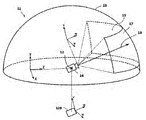
- FIG. 4 is a diagram conceptually representing one aspect of expressing the virtual space 11 according to a certain embodiment.
- the virtual space 11 has an all-sky spherical structure that covers the entire center 12 in the 360-degree direction.
- the celestial sphere in the upper half of the virtual space 11 is illustrated so as not to complicate the explanation.
- Each mesh is defined in the virtual space 11.
- the position of each mesh is predetermined as a coordinate value in the XYZ coordinate system, which is a global coordinate system defined in the virtual space 11.
- the computer 200 associates each partial image constituting the panoramic image 13 (still image, moving image, etc.) expandable in the virtual space 11 with each corresponding mesh in the virtual space 11.
- the virtual space 11 defines an XYZ coordinate system with the center 12 as the origin.
- the XYZ coordinate system is, for example, parallel to the real coordinate system.
- the horizontal direction, vertical direction (vertical direction), and front-back direction in the XYZ coordinate system are defined as the X-axis, the Y-axis, and the Z-axis, respectively. Therefore, the X-axis (horizontal direction) of the XYZ coordinate system is parallel to the x-axis of the real coordinate system, and the Y-axis (vertical direction) of the XYZ coordinate system is parallel to the y-axis of the real coordinate system.
- the Z-axis (front-back direction) is parallel to the z-axis of the real coordinate system.
- the virtual camera 14 is arranged at the center 12 of the virtual space 11.
- the processor 210 displays an image captured by the virtual camera 14 on the monitor 130 of the HMD 120.
- the virtual camera 14 moves in the virtual space 11 in the same manner in conjunction with the movement of the HMD 120 in the real space.
- changes in the position and inclination of the HMD 120 in the real space can be similarly reproduced in the virtual space 11.
- the virtual camera 14 is defined with an uvw field-of-view coordinate system.
- the uvw field-of-view coordinate system of the virtual camera 14 in the virtual space 11 is defined to be linked to the uvw field-of-view coordinate system of the HMD 120 in the real space (real coordinate system). Therefore, when the inclination of the HMD 120 changes, the inclination of the virtual camera 14 also changes accordingly.
- the virtual camera 14 can also move in the virtual space 11 in conjunction with the movement of the user 5 wearing the HMD 120 in the real space.
- the processor 210 of the computer 200 defines the field of view 15 in the virtual space 11 based on the position and tilt (reference line of sight 16) of the virtual camera 14.
- the visual field area 15 corresponds to an area of the virtual space 11 that is visually recognized by the user 5 wearing the HMD 120. That is, the position of the virtual camera 14 can be said to be the viewpoint of the user 5 in the virtual space 11.
- the line of sight of the user 5 detected by the gaze sensor 140 is a direction in the viewpoint coordinate system when the user 5 visually recognizes an object.
- the uvw field-of-view coordinate system of the HMD 120 is equal to the viewpoint coordinate system when the user 5 visually recognizes the monitor 130.
- the uvw field-of-view coordinate system of the virtual camera 14 is linked to the uvw field-of-view coordinate system of the HMD 120. Therefore, the HMD system 100 according to a certain aspect can consider the line of sight of the user 5 detected by the gaze sensor 140 as the line of sight of the user 5 in the uvw field of view coordinate system of the virtual camera 14.
- FIG. 5 is a top view of the head of the user 5 who wears the HMD 120 according to an embodiment.
- the gaze sensor 140 detects each line of sight of the user 5's right and left eyes. In a certain aspect, when the user 5 is looking near, the gaze sensor 140 detects the lines of sight R1 and L1. In another aspect, when the user 5 is looking far away, the gaze sensor 140 detects the lines of sight R2 and L2. In this case, the angle formed by the lines of sight R2 and L2 with respect to the roll axis w is smaller than the angle formed by the lines of sight R1 and L1 with respect to the roll axis w. The gaze sensor 140 transmits the detection result to the computer 200.
- the computer 200 When the computer 200 receives the detection values of the lines of sight R1 and L1 from the gaze sensor 140 as the detection result of the line of sight, the computer 200 identifies the gaze point N1 which is the intersection of the lines of sight R1 and L1 based on the detected values. On the other hand, when the computer 200 receives the detected values of the lines of sight R2 and L2 from the gaze sensor 140, the computer 200 identifies the intersection of the lines of sight R2 and L2 as the gaze point. The computer 200 identifies the line of sight N0 of the user 5 based on the position of the specified gazing point N1.
- the computer 200 detects, for example, the extending direction of the straight line passing through the midpoint of the straight line connecting the right eye R and the left eye L of the user 5 and the gazing point N1 as the line of sight N0.
- the line of sight N0 is the direction in which the user 5 actually directs the line of sight with both eyes.
- the line of sight N0 corresponds to the direction in which the user 5 actually directs the line of sight with respect to the field of view area 15.
- the HMD system 100 may include a television broadcast receiving tuner. According to such a configuration, the HMD system 100 can display a television program in the virtual space 11.
- the HMD system 100 may include a communication circuit for connecting to the Internet or a telephone function for connecting to a telephone line.
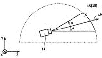
- FIG. 6 is a diagram showing a YZ cross section of the field of view region 15 viewed from the X direction in the virtual space 11.
- FIG. 7 is a diagram showing an XZ cross section of the field of view region 15 viewed from the Y direction in the virtual space 11.
- the field of view region 15 in the YZ cross section includes the region 18.
- the region 18 is defined by the position of the virtual camera 14, the reference line of sight 16, and the YZ cross section of the virtual space 11.
- the processor 210 defines a range including the polar angle ⁇ centered on the reference line of sight 16 in the virtual space as a region 18.
- the field of view region 15 in the XZ cross section includes the region 19.
- the region 19 is defined by the position of the virtual camera 14, the reference line of sight 16, and the XZ cross section of the virtual space 11.
- the processor 210 defines a range including the azimuth angle ⁇ centered on the reference line of sight 16 in the virtual space 11 as a region 19.
- the polar angle ⁇ and the azimuth angle ⁇ are determined according to the position of the virtual camera 14 and the inclination (orientation) of the virtual camera 14.
- the HMD system 100 provides the user 5 with a field of view in the virtual space 11 by displaying the field of view image 17 on the monitor 130 based on the signal from the computer 200.
- the visual field image 17 is an image corresponding to a portion of the panoramic image 13 corresponding to the visual field region 15.
- the virtual camera 14 also moves in conjunction with the movement.
- the position of the visual field region 15 in the virtual space 11 changes.
- the visual field image 17 displayed on the monitor 130 is updated to an image of the panoramic image 13 superimposed on the visual field region 15 in the direction in which the user 5 faces in the virtual space 11.
- the user 5 can visually recognize a desired direction in the virtual space 11.
- the inclination of the virtual camera 14 corresponds to the line of sight (reference line of sight 16) of the user 5 in the virtual space 11, and the position where the virtual camera 14 is arranged corresponds to the viewpoint of the user 5 in the virtual space 11. Therefore, by changing the position or tilt of the virtual camera 14, the image displayed on the monitor 130 is updated, and the field of view of the user 5 is moved.
- the HMD system 100 can give the user 5 a high sense of immersion in the virtual space 11.
- the processor 210 may move the virtual camera 14 in the virtual space 11 in conjunction with the movement of the user 5 wearing the HMD 120 in the real space. In this case, the processor 210 identifies an image region (field of view region 15) projected onto the monitor 130 of the HMD 120 based on the position and tilt of the virtual camera 14 in the virtual space 11.
- the virtual camera 14 may include two virtual cameras, a virtual camera for providing an image for the right eye and a virtual camera for providing an image for the left eye. Appropriate parallax is set for the two virtual cameras so that the user 5 can recognize the three-dimensional virtual space 11.
- the virtual camera 14 may be realized by one virtual camera. In this case, an image for the right eye and an image for the left eye may be generated from the image obtained by one virtual camera.
- the virtual camera 14 includes two virtual cameras, and the roll axis (w) generated by synthesizing the roll axes of the two virtual cameras is adapted to the roll axis (w) of the HMD 120. The technical idea of the present disclosure is illustrated as being configured as such.
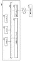
- FIG. 8 is a diagram showing a schematic configuration of a controller 300 according to an embodiment.
- the controller 300 may include a right controller 300R and a left controller (not shown).
- the right controller 300R is operated by the right hand of the user 5.
- the left controller is operated by the left hand of the user 5.
- the right controller 300R and the left controller are symmetrically configured as separate devices. Therefore, the user 5 can freely move the right hand holding the right controller 300R and the left hand holding the left controller.
- the controller 300 may be an integrated controller that accepts operations of both hands.
- the right controller 300R will be described.
- the right controller 300R includes a grip 310, a frame 320, and a top surface 330.
- the grip 310 is configured to be gripped by the right hand of the user 5.
- the grip 310 may be held by the palm of the user 5's right hand and three fingers (middle finger, ring finger, little finger).
- the grip 310 includes buttons 340, 350 and a motion sensor 420.
- the button 340 is arranged on the side surface of the grip 310 and accepts an operation by the middle finger of the right hand.
- the button 350 is arranged in front of the grip 310 and accepts an operation by the index finger of the right hand.
- the buttons 340,350 are configured as trigger-type buttons.
- the motion sensor 420 is built in the housing of the grip 310. If the movement of the user 5 can be detected from around the user 5 by a camera or other device, the grip 310 may not include the motion sensor 420.
- the frame 320 includes a plurality of infrared LEDs 360 arranged along its circumferential direction.
- the infrared LED 360 emits infrared rays as the program progresses while the program using the controller 300 is being executed.
- the infrared rays emitted from the infrared LED 360 can be used to detect each position and orientation (tilt, orientation) of the right controller 300R and the left controller.
- infrared LEDs 360 arranged in two rows are shown, but the number of arrays is not limited to that shown in FIG. An array of one column or three or more columns may be used.
- the top surface 330 includes buttons 370, 380 and an analog stick 390.
- the buttons 370 and 380 are configured as push-type buttons. Buttons 370 and 380 accept operations by the thumb of the user 5's right hand.
- the analog stick 390 accepts an operation 360 degrees in any direction from the initial position (neutral position) in a certain aspect.
- the operation includes, for example, an operation for moving an object arranged in the virtual space 11.
- the right controller 300R and the left controller include a battery for driving the infrared LED 360 and other components. Batteries include, but are not limited to, rechargeable, button type, dry cell type and the like.
- the right controller 300R and the left controller may be connected to, for example, the USB interface of the computer 200. In this case, the right controller 300R and the left controller do not require batteries.
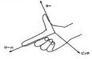
- the yaw, roll, and pitch directions are defined with respect to the right hand of the user 5.
- the direction in which the thumb extends is the yaw direction
- the direction in which the index finger extends is the roll direction
- the direction perpendicular to the plane defined by the yaw direction axis and the roll direction axis is the pitch direction. Is defined as.
- FIG. 9 is a block diagram showing an example of the hardware configuration of the server 600 according to a certain embodiment.
- the server 600 includes a processor 610, a memory 620, a storage 630, an input / output interface 640, and a communication interface 650 as main components. Each component is connected to bus 660, respectively.
- the processor 610 executes a series of instructions contained in the program stored in the memory 620 or the storage 630 based on the signal given to the server 600 or the condition that a predetermined condition is satisfied.
- the processor 610 is implemented as a CPU), GPU, MPU, FPGA or other device.
- Memory 620 temporarily stores programs and data.
- the program is loaded from storage 630, for example.
- the data includes data input to the server 600 and data generated by the processor 610.
- the memory 620 is realized as a RAM or other volatile memory.
- Storage 630 permanently holds programs and data.
- the storage 630 is realized as, for example, a ROM, a hard disk device, a flash memory, or other non-volatile storage device.
- the program stored in the storage 630 may include a program for providing a virtual space in the HMD system 100, a simulation program, a game program, a user authentication program, and a program for realizing communication with the computer 200.
- the data stored in the storage 630 may include data, objects, and the like for defining the virtual space.
- the storage 630 may be realized as a removable storage device such as a memory card.
- a configuration using programs and data stored in an external storage device may be used instead of the storage 630 built into the server 600. According to such a configuration, for example, in a scene where a plurality of HMD systems 100 are used such as an amusement facility, it is possible to update programs and data at once.
- the input / output interface 640 communicates a signal with the input / output device.
- the input / output interface 640 is implemented using USB, DVI, HDMI® and other terminals.
- the input / output interface 640 is not limited to the above.
- the communication interface 650 is connected to the network 2 and communicates with the computer 200 connected to the network 2.
- the communication interface 650 is implemented as, for example, a LAN or other wired communication interface, or a WiFi, Bluetooth, NFC or other wireless communication interface.
- the communication interface 650 is not limited to the above.
- the processor 610 accesses the storage 630, loads one or more programs stored in the storage 630 into the memory 620, and executes a series of instructions contained in the program.
- the one or more programs may include an operating system of the server 600, an application program for providing the virtual space, game software that can be executed in the virtual space, and the like.
- the processor 610 may send a signal to the computer 200 to provide virtual space via the input / output interface 640.
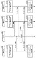
- FIG. 10 is a block diagram showing a computer 200 according to an embodiment as a module configuration.
- the computer 200 includes a control module 510, a rendering module 520, a memory module 530, and a communication control module 540.
- the control module 510 and the rendering module 520 are implemented by the processor 210.
- the plurality of processors 210 may operate as the control module 510 and the rendering module 520.
- the memory module 530 is realized by the memory 220 or the storage 230.
- the communication control module 540 is realized by the communication interface 250.
- the control module 510 controls the virtual space 11 provided to the user 5.
- the control module 510 defines the virtual space 11 in the HMD system 100 by using the virtual space data representing the virtual space 11.
- the virtual space data is stored in, for example, the memory module 530.
- the control module 510 may generate virtual space data or acquire virtual space data from a server 600 or the like.
- the control module 510 arranges an object in the virtual space 11 by using the object data representing the object.
- the object data is stored in, for example, the memory module 530.
- the control module 510 may generate object data or acquire object data from a server 600 or the like.
- the objects are, for example, an avatar object that is the alter ego of the user 5, a character object, an operation object such as a virtual hand operated by the controller 300, a landscape including forests, mountains, etc. arranged as the story of the game progresses, a cityscape, and animals. Etc. may be included.
- the control module 510 arranges the avatar object of the user 5 of another computer 200 connected via the network 2 in the virtual space 11. In a certain aspect, the control module 510 arranges the avatar object of the user 5 in the virtual space 11. In a certain aspect, the control module 510 arranges an avatar object imitating the user 5 in the virtual space 11 based on the image including the user 5. In another aspect, the control module 510 arranges in the virtual space 11 an avatar object that has been selected by the user 5 from among a plurality of types of avatar objects (for example, an object imitating an animal or a deformed human object). do.
- a plurality of types of avatar objects for example, an object imitating an animal or a deformed human object.
- the control module 510 identifies the inclination of the HMD 120 based on the output of the HMD sensor 410. In another aspect, the control module 510 identifies the tilt of the HMD 120 based on the output of the sensor 190, which functions as a motion sensor.
- the control module 510 detects organs (for example, mouth, eyes, eyebrows) constituting the face of the user 5 from the images of the face of the user 5 generated by the first camera 150 and the second camera 160.
- the control module 510 detects the movement (shape) of each detected organ.
- the control module 510 detects the line of sight of the user 5 in the virtual space 11 based on the signal from the gaze sensor 140.
- the control module 510 detects the viewpoint position (coordinate value in the XYZ coordinate system) at which the detected line of sight of the user 5 and the celestial sphere in the virtual space 11 intersect. More specifically, the control module 510 detects the viewpoint position based on the line of sight of the user 5 defined by the uvw coordinate system and the position and inclination of the virtual camera 14.
- the control module 510 transmits the detected viewpoint position to the server 600.
- the control module 510 may be configured to transmit line-of-sight information representing the line-of-sight of the user 5 to the server 600. In such a case, the viewpoint position can be calculated based on the line-of-sight information received by the server 600.
- the control module 510 reflects the movement of the HMD 120 detected by the HMD sensor 410 on the avatar object. For example, the control module 510 detects that the HMD 120 is tilted and tilts and arranges the avatar object. The control module 510 reflects the detected movement of the facial organ on the face of the avatar object arranged in the virtual space 11. The control module 510 receives the line-of-sight information of the other user 5 from the server 600 and reflects it in the line-of-sight of the avatar object of the other user 5. In a certain aspect, the control module 510 reflects the movement of the controller 300 on the avatar object and the operation object. In this case, the controller 300 includes a motion sensor, an acceleration sensor, a plurality of light emitting elements (for example, infrared LEDs), and the like for detecting the movement of the controller 300.
- the controller 300 includes a motion sensor, an acceleration sensor, a plurality of light emitting elements (for example, infrared LEDs), and the like for detecting the movement of the controller 300
- the control module 510 arranges an operation object for receiving the operation of the user 5 in the virtual space 11 in the virtual space 11.
- the user 5 operates, for example, an object arranged in the virtual space 11.
- the operation object may include, for example, a hand object which is a virtual hand corresponding to the hand of the user 5.
- the control module 510 moves the hand object in the virtual space 11 so as to be linked to the movement of the user 5's hand in the real space based on the output of the motion sensor 420.
- the manipulation object can correspond to the hand portion of the avatar object.
- the control module 510 detects the collision.
- the control module 510 can detect, for example, the timing at which the collision area of one object and the collision area of another object touch each other, and when the detection is made, a predetermined process is performed.
- the control module 510 can detect the timing when the object and the object are separated from the touching state, and when the detection is made, a predetermined process is performed.
- the control module 510 can detect that the object is in contact with the object. For example, when the operation object and another object are touched, the control module 510 detects that the operation object and the other object are in contact with each other, and performs a predetermined process.
- the control module 510 controls the image display on the monitor 130 of the HMD 120.
- the control module 510 arranges the virtual camera 14 in the virtual space 11.
- the control module 510 controls the position of the virtual camera 14 in the virtual space 11 and the inclination (orientation) of the virtual camera 14.
- the control module 510 defines the field of view 15 according to the inclination of the head of the user 5 wearing the HMD 120 and the position of the virtual camera 14.
- the rendering module 520 generates a visual field image 17 to be displayed on the monitor 130 based on the determined visual field region 15.
- the field of view image 17 generated by the rendering module 520 is output to the HMD 120 by the communication control module 540.
- control module 510 When the control module 510 detects an utterance using the microphone 170 of the user 5 from the HMD 120, the control module 510 identifies the computer 200 to which the voice data to be transmitted corresponding to the utterance is transmitted. The voice data is transmitted to the computer 200 identified by the control module 510. When the control module 510 receives voice data from another user's computer 200 via the network 2, the control module 510 outputs the voice (utterance) corresponding to the voice data from the speaker 180.
- the memory module 530 holds data used by the computer 200 to provide the virtual space 11 to the user 5.
- the memory module 530 holds spatial information, object information, and user information.
- Spatial information holds one or more templates defined to provide the virtual space 11.
- the object information includes a plurality of panoramic images 13 constituting the virtual space 11 and object data for arranging the objects in the virtual space 11.
- the panoramic image 13 may include a still image and a moving image.
- the panoramic image 13 may include an image in the unreal space and an image in the real space. Examples of images in unreal space include images generated by computer graphics.
- the user information holds a user ID that identifies the user 5.
- the user ID may be, for example, an IP (Internet Protocol) address or a MAC (Media Access Control) address set in the computer 200 used by the user. In another aspect, the user ID may be set by the user.
- the user information includes a program for operating the computer 200 as a control device of the HMD system 100 and the like.
- the data and programs stored in the memory module 530 are input by the user 5 of the HMD 120.
- the processor 210 downloads a program or data from a computer (for example, a server 600) operated by a business operator that provides the content, and stores the downloaded program or data in the memory module 530.
- the communication control module 540 may communicate with the server 600 and other information communication devices via the network 2.
- control module 510 and the rendering module 520 may be implemented using, for example, Unity® provided by Unity Technologies.
- control module 510 and the rendering module 520 can also be realized as a combination of circuit elements that realize each process.
- the processing in the computer 200 is realized by the hardware and the software executed by the processor 210.
- Such software may be pre-stored in a hard disk or other memory module 530.
- the software may be stored on a CD-ROM or other computer-readable non-volatile data recording medium and distributed as a program product. Alternatively, the software may be provided as a downloadable program product by an information provider connected to the Internet or other networks.
- Such software is read from a data recording medium by an optical disk drive or other data reader, or downloaded from a server 600 or other computer via a communication control module 540, and then temporarily stored in a storage module. ..
- the software is read from the storage module by the processor 210 and stored in RAM in the form of an executable program. Processor 210 executes the program.
- FIG. 11 is a sequence chart showing a part of the processing performed in the HMD set 110 according to an embodiment.
- step S1110 the processor 210 of the computer 200 specifies the virtual space data as the control module 510 and defines the virtual space 11.
- step S1120 the processor 210 initializes the virtual camera 14. For example, the processor 210 arranges the virtual camera 14 at a predetermined center point 12 in the virtual space 11 in the work area of the memory, and directs the line of sight of the virtual camera 14 in the direction in which the user 5 is facing.
- step S1130 the processor 210 generates the field of view image data for displaying the initial field of view image as the rendering module 520.
- the generated visual field image data is output to the HMD 120 by the communication control module 540.
- step S1132 the monitor 130 of the HMD 120 displays the visual field image based on the visual field image data received from the computer 200.
- the user 5 wearing the HMD 120 can recognize the virtual space 11 when he / she visually recognizes the field of view image.
- step S1134 the HMD sensor 410 detects the position and tilt of the HMD 120 based on the plurality of infrared rays emitted from the HMD 120.
- the detection result is output to the computer 200 as motion detection data.
- step S1140 the processor 210 identifies the viewing direction of the user 5 wearing the HMD 120 based on the position and inclination included in the motion detection data of the HMD 120.
- step S1150 the processor 210 executes the application program and arranges the object in the virtual space 11 based on the instruction included in the application program.
- step S1160 the controller 300 detects the operation of the user 5 based on the signal output from the motion sensor 420, and outputs the detection data representing the detected operation to the computer 200.
- the operation of the controller 300 by the user 5 may be detected based on an image from a camera arranged around the user 5.
- step S1170 the processor 210 detects the operation of the controller 300 by the user 5 based on the detection data acquired from the controller 300.
- step S1180 the processor 210 generates the field of view image data based on the operation of the controller 300 by the user 5.
- the generated visual field image data is output to the HMD 120 by the communication control module 540.
- step S1190 the HMD 120 updates the visual field image based on the received visual field image data, and displays the updated visual field image on the monitor 130.
- FIGS. 12A and 12B An avatar object according to the present embodiment will be described with reference to FIGS. 12A and 12B.
- a user 5A the user of the HMD set 110A is referred to as a user 5A
- the user of the HMD set 110B is referred to as a user 5B
- the user of the HMD set 110C is referred to as a user 5C
- the user of the HMD set 110D is referred to as a user 5D.
- A is added to the reference code of each component related to the HMD set 110A
- B is added to the reference code of each component related to the HMD set 110B
- C is added to the reference code of each component related to the HMD set 110C
- a D is added to the reference code of each component with respect to 110D.
- the HMD 120A is included in the HMD set 110A.
- FIG. 12A is a schematic diagram showing a situation in which each HMD 120 provides the virtual space 11 to the user 5 in the network 2.
- the computers 200A to 200D provide the virtual spaces 11A to 11D to the users 5A to 5D via the HMDs 120A to 120D, respectively.
- the virtual space 11A and the virtual space 11B are composed of the same data.
- the computer 200A and the computer 200B share the same virtual space.
- the avatar object 6A of the user 5A and the avatar object 6B of the user 5B exist.
- the avatar object 6A in the virtual space 11A and the avatar object 6B in the virtual space 11B are each equipped with the HMD 120, but this is for the sake of clarity, and in reality, these objects are equipped with the HMD 120. Not.
- the processor 210A may place a virtual camera 14A that captures the field of view image 17A of the user 5A at the eye position of the avatar object 6A.
- FIG. 12 (B) is a diagram showing the field of view image 17A of the user 5A in FIG. 12 (A).
- the visual field image 17A is an image displayed on the monitor 130A of the HMD 120A.
- the field of view image 17A is an image generated by the virtual camera 14A.
- the avatar object 6B of the user 5B is displayed in the field of view image 17A.
- the avatar object 6A of the user 5A is also displayed in the field of view image of the user 5B.
- the user 5A can communicate with the user 5B through the virtual space 11A by dialogue. More specifically, the voice of the user 5A acquired by the microphone 170A is transmitted to the HMD17120B of the user 5B via the server 600, and is output from the speaker 180B provided in the HMD120B. The voice of the user 5B is transmitted to the HMD 120A of the user 5A via the server 600, and is output from the speaker 180A provided in the HMD 120A.
- the operation of the user 5B (the operation of the HMD 120B and the operation of the controller 300B) is reflected in the avatar object 6B arranged in the virtual space 11A by the processor 210A.
- the user 5A can recognize the operation of the user 5B through the avatar object 6B.
- FIG. 13 is a sequence chart showing a part of the processing executed in the HMD system 100 according to the present embodiment.
- the HMD set 110D is not shown in FIG. 13, the HMD set 110D operates in the same manner as the HMD sets 110A, 110B, and 110C.
- A is added to the reference code of each component related to the HMD set 110A
- B is added to the reference code of each component related to the HMD set 110B
- C is added to the reference code of each component related to the HMD set 110C. It shall be attached and D shall be attached to the reference code of each component with respect to the HMD set 110D.
- step S1310A the processor 210A in the HMD set 110A acquires the avatar information for determining the operation of the avatar object 6A in the virtual space 11A.
- This avatar information includes information about the avatar such as motion information, face tracking data, and voice data.
- the motion information includes information indicating a temporal change in the position and inclination of the HMD 120A, information indicating the hand motion of the user 5A detected by the motion sensor 420A or the like, and the like.
- the face tracking data includes data for specifying the position and size of each part of the face of the user 5A. Examples of the face tracking data include data indicating the movement of each organ constituting the face of the user 5A and line-of-sight data.
- Examples of the voice data include data indicating the voice of the user 5A acquired by the microphone 170A of the HMD 120A.
- the avatar information may include information that identifies the avatar object 6A or the user 5A associated with the avatar object 6A, information that identifies the virtual space 11A in which the avatar object 6A exists, and the like. Examples of the information that identifies the avatar object 6A and the user 5A include a user ID. Information that identifies the virtual space 11A in which the avatar object 6A exists includes a room ID.
- the processor 210A transmits the avatar information acquired as described above to the server 600 via the network 2.
- step S1310B the processor 210B in the HMD set 110B acquires the avatar information for determining the operation of the avatar object 6B in the virtual space 11B and transmits it to the server 600, as in the process in step S1310A.
- step S1310C the processor 210B in the HMD set 110B acquires the avatar information for determining the operation of the avatar object 6C in the virtual space 11C and transmits it to the server 600.
- step S1320 the server 600 temporarily stores the player information received from each of the HMD set 110A, the HMD set 110B, and the HMD set 110C.
- the server 600 integrates the avatar information of all users (users 5A to 5C in this example) associated with the common virtual space 11 based on the user ID, room ID, and the like included in each avatar information. Then, the server 600 transmits the integrated avatar information to all the users associated with the virtual space 11 at a predetermined timing. As a result, the synchronization process is executed.
- the HMD set 110A, the HMD set 110B, and the HMD 11020C can share each other's avatar information at substantially the same timing.
- each HMD set 110A to 110C executes the process of steps S1330A to S1330C based on the avatar information transmitted from the server 600 to each HMD set 110A to 110C.
- the process of step S1330A corresponds to the process of step S1180 in FIG.
- step S1330A the processor 210A in the HMD set 110A updates the information of the avatar objects 6B and the avatar objects 6C of the other users 5B and 5C in the virtual space 11A. Specifically, the processor 210A updates the position and orientation of the avatar object 6B in the virtual space 11 based on the motion information included in the avatar information transmitted from the HMD set 110B. For example, the processor 210A updates the information (position, orientation, etc.) of the avatar object 6B included in the object information stored in the memory module 530. Similarly, the processor 210A updates the information (position, orientation, etc.) of the avatar object 6C in the virtual space 11 based on the motion information included in the avatar information transmitted from the HMD set 110C.
- step S1330B the processor 210B in the HMD set 110B updates the information of the avatar objects 6A, 6C of the users 5A, 5C in the virtual space 11B, as in the process in step S1330A.
- step S1330C the processor 210C in the HMD set 110C updates the information of the avatar objects 6A, 6B of the users 5A, 5B in the virtual space 11C.
- FIG. 14 is a block diagram showing a detailed configuration of a module of the computer 200 according to an embodiment.
- the control module 510 includes a virtual camera control module 1421, a view area determination module 1422, a reference line-of-sight identification module 1423, a virtual space definition module 1424, a virtual object generation module 1425, and an operation object. It includes a control module 1426 and a browsing module 1427.
- the rendering module 520 includes a field of view image generation module 1438.
- the memory module 530 holds spatial information 1431 and user information 1432.
- the virtual camera control module 1421 arranges the virtual camera 14 in the virtual space 11.
- the virtual camera control module 1421 controls the arrangement position of the virtual camera 14 in the virtual space 11 and the orientation (tilt) of the virtual camera 14.
- the field-of-view area determination module 1422 defines the field-of-view area 15 according to the orientation of the head of the user 5 wearing the HMD 120 and the arrangement position of the virtual camera 14.
- the visual field image generation module 1438 generates a visual field image 17 to be displayed on the monitor 130 based on the determined visual field region 15.
- the reference line-of-sight identification module 1423 identifies the line-of-sight of the user 5 based on the signal from the gaze sensor 140.
- the virtual space definition module 1424 defines the virtual space 11 in the HMD system 100 by generating virtual space data representing the virtual space 11.
- the virtual object generation module 1425 generates an object to be arranged in the virtual space 11.
- the operation object control module 1426 arranges an operation object for receiving the operation of the user 5 in the virtual space 11 in the virtual space 11.
- the user 5 operates, for example, an object arranged in the virtual space 11.
- the operating object may include, for example, a hand object corresponding to the hand of the user 5 wearing the HMD 120.
- the manipulation object may correspond to the hand portion of the avatar object described below.
- the browsing module 1427 makes it possible to perform web browsing in the virtual space 11.
- the browsing module 1427 arranges a web browser (hereinafter, also referred to as a browser window) in the virtual space 11.
- the browsing module 1427 arranges a menu window in the virtual space 11 for receiving an operation of the user 5 regarding web browsing. For example, when the user 5 inputs a URL on a browser window or a menu window, the browsing module receives an information resource from a server corresponding to the URL and provides an image based on the information resource in the browser window.
- the browsing module 1427 will place an image based on that information resource in virtual space 11 or another virtual space, or in the fusion space of the virtual world and the real world. It can be provided as XR content developed in.
- the "XR content” means, for example, by changing the position and inclination of the HMD 120, the user 5 can freely view the viewpoint in the virtual space or in the fusion space between the virtual world and the real world. Content that can be changed.
- Specific examples of the "XR content” include VR content, AR content, MR content, SR (Substitutional Reality) content, and the like.
- the "XR content” preferably includes, for example, a virtual space or a fusion space developed at a predetermined angle (for example, 180 degrees, 360 degrees, etc.). In the following, the case where the “XR content” is the “VR content” will be taken as an example, but the present disclosure can be similarly applied to other XR contents.
- the "VR content” refers to content in which the user 5 can freely change the viewpoint in the virtual space by changing the position and inclination of the HMD 120, for example, a predetermined angle (for example, 180). It is preferably provided as a virtual space including a spatial image developed at (degrees, 360 degrees, etc.), and more preferably provided as a virtual space (so-called 360-degree contents) including a 360-degree spatial image.
- the virtual space including the 360-degree space image for example, the virtual camera is arranged at the center position of the virtual space, and the 360-degree space image is displayed on the surface of the virtual space.
- content includes, for example, videos, still images, games, music, SNS, (Social Networking Service), maps, news, web media, images taken by cameras, and predetermined services (for example, video distribution and product sales). ), The top page of the website and other web pages.
- the control module 510 detects the collision.
- the control module 510 can detect, for example, the timing at which a certain object and another object touch each other, and when the detection is made, a predetermined process is performed.
- the control module 510 can detect the timing when the object and the object are separated from the touching state, and when the detection is made, a predetermined process is performed.
- the control module 510 can detect that the object is in contact with the object. Specifically, when the operation object and another object are touched, the control module 510 detects that the operation object and the other object are in contact with each other, and performs a predetermined process.
- the memory module 530 holds data used by the computer 200 to provide the virtual space 11 to the user 5.
- the memory module 530 holds spatial information 1431 and user information 1432.
- Spatial information 1431 holds one or more templates defined to provide the virtual space 11. Spatial information 1431 may include information about objects placed in the virtual space 11.
- the user information 1432 holds a program for operating the computer 200 as a control device for the HMD system 100, a program for operating the browsing module 1427, and the like.
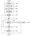
- FIG. 15 is a flowchart showing an example of an operation process executed in the computer 200 according to a certain embodiment.
- the operation of the user 5 can be executed, for example, via the controller 300, the movement of a part of the body of the user 5 such as hand tracking, or the gaze sensor 140.
- step S1501 the processor 210 of the computer 200 identifies the virtual space data as the control module 510 and defines the virtual space.
- the defined virtual space is provided to the HMD 120.
- the virtual space defined in step S1501 is a virtual space including a spatial image developed at a predetermined angle (for example, 180 degrees, 360 degrees, etc.), and in the following, a 360 degree space developed over 360 degrees.
- a predetermined angle for example, 180 degrees, 360 degrees, etc.
- step S1502 the processor 210 arranges the browser window in the virtual space defined in step S1501.
- the browser window may be arranged according to, for example, an operation for executing the web browser by the user 5, or is initially arranged in the virtual space when the virtual space is defined in step S1501. It may be placed as an object.
- the processor 210 virtualizes a menu object that displays an operation menu when browsing the web, and an information display object that displays supplementary information and advertising information about web contents displayed in the browser window. It may be arranged in the space.
- “web content” means content provided on the web, for example.
- FIG. 16 is a schematic diagram showing an example of a virtual space according to a certain embodiment.
- FIG. 17 is a schematic view showing an XZ cross section of the virtual space shown in FIG. 16 as viewed from the Y-axis direction.
- the virtual space 1611 is developed in the celestial sphere, but the present invention is not limited to this example.
- the virtual space 1611 may be expanded into a space separated by, for example, a 3D object (for example, a building such as a house).
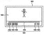
- a browser window 1621 and a virtual camera 1614 are arranged in the virtual space 1611.
- the web content provided by the server is displayed in the browser window 1621.
- the shape and the like of the browser window 1621 is not particularly limited, but is generally a flat plate shape as shown by FIGS. 16 and 17. Therefore, when the web content is displayed in the browser window 1621, the web content is also displayed in a plane.
- the browser window 1621 having a planar shape is arranged in the virtual space 1611 including the 360-degree spatial image developed over 360 degrees.
- step S1503 the processor 210 receives an access request to the URL address that provides the web content.
- the flowchart of FIG. 15 is not applied only to the moving image content, for example, a still image. It can also be applied when there is a request to access the URL address that provides the web page.
- the access request is executed based on, for example, an operation input by the user 5.
- the processor 210 accesses the designated server based on the access request, and acquires, for example, an information resource for providing (playing) the moving image content provided by the server in the browser window.
- step S1504 the processor 210 starts providing the moving image content in the browser window based on the acquired information resource. Specifically, the processor 210 starts automatic playback of the moving image content in the browser window.
- step S1504 If the video content started to be provided in step S1504 cannot be provided as VR content (NO in step S1505), the provision of the video content in the browser window is continued. After that, the processor 210 ends the process according to a predetermined opportunity.
- step S1504 if the moving image content started to be provided in step S1504 can be provided as VR content (YES in step S1505), the process proceeds to step S1506.
- the process of step S1506 is executed in a predetermined first period of the period in which the moving image content is provided on the browser window.
- the "first period” is not particularly limited, but is preferably a period from the start of providing the web content on the browser window until a predetermined time (for example, 10 seconds) elapses.
- the "first period” may be a period from the display of the UI (User Interface) image for operating the web content to the elapse of a predetermined time.
- both of the above-mentioned two periods may be referred to as a "first period”.
- the period from the start of the reproduction of the moving image content (process of step S1504) on the browser window to the elapse of a predetermined time will be described as the “first period”.
- the reproduction of the moving image content in step S1504 is automatically executed according to the user 5 selecting the moving image content.
- the reproduction of the moving image content in step S1504 may be executed in response to the operation input for the reproduction after the user 5 selects the moving image content.
- step S1506 the processor 210 notifies the user that the moving image content can be used as the VR content in a manner emphasized more than in the second period.
- the "second period" means, for example, the period during which the web content is provided on the browser window, excluding the first period.
- notifying the user in an emphasized manner means, for example, displaying and notifying an image that is not displayed in the second period, or indicating the size and color of the image for notifying, the arrangement location, the display method, and the like. It includes making changes that are more visually noticeable than the period.
- notifying the user in an emphasized manner may be notification via hearing, for example, by emitting a guide voice (voice notifying that it can be used as VR content) only in the first period. There may be.
- the processor 210 When the processor 210 receives the change request to the VR mode in step S1507 (YES in step S1507), the processor 210 provides the moving image content as VR content in step S1508. After that, the processor 210 ends the process according to a predetermined opportunity.
- step S1507 if the processor 210 has not received the change request to the VR mode (NO in step S1507) and is in the first period (NO in step S1509), the processor 210 is in step S1506. Continue the notification in the emphasized mode based on the process.
- step S1507 the processor 210 has not received the change request to the VR mode (NO in step S1507), and in step S1509, the processor 210 determines that the first period has ended. (YES in step S1509), and in step S1510, the processor 210 ends the notification in the emphasized mode based on the process of step S1506. After that, the processor 210 ends the process according to a predetermined opportunity.
- steps S1506 to S1510 will be described in detail with reference to FIGS. 18 (A) to 18 (D), FIGS. 19 (A) to (B), and FIG. 20.
- FIGS. 18A to 18D is a schematic diagram showing an example of notification (hereinafter, also referred to as “highlighting”) in the emphasized mode in step S1506.
- FIGS. 19A to 19B is a schematic diagram showing an example of the display contents of the browser window after the notification in the mode emphasized in step S1510 is completed.
- the moving image content 1622 is provided in the browser window 1621.
- FIG. 18A which is an example of highlighting
- a first image 1823 is further displayed, which informs only that the moving image content 1822 can be used as VR content.
- the first image 1823 is, for example, an icon image suggesting only that the moving image content 1822 can be used as VR content.
- FIG. 19A which is an example after the highlighting is completed, the moving image content 1622 is provided in the browser window 1621, but the first image 1823 is not displayed. Therefore, it can be said that FIG. 18 (A) is highlighted more than FIG. 19 (A) by displaying the first image 1823 which is not displayed in FIG. 19 (A).
- the "first image” is an image that only notifies that the web content can be used as VR content.
- the “first image” is not particularly limited as long as it satisfies the above, and examples thereof include an icon image, a text image, and an image in which an icon and text are combined.
- An operation UI (for example, operation UI 1831 described later) including various icons associated with functions related to operations of web contents (video contents) such as play, stop, fast forward, and rewind is used as VR contents. Even if it contains an icon image suggesting that it can be used, it is not included in the first image. Similarly, even if the image suggests that it can be used as VR content, the image displayed integrally with various icons and the like associated with other functions (for example, the VR button 1837 described later) is the first. Not included in one image.
- the example of FIG. 19B is an example in which the operation UI 1831 is displayed in the browser window 1621 in response to the user 5 inputting a predetermined operation from the state of FIG. 19A.
- the operation UI 1831 is a UI image that integrally includes a play / stop button 1832, a rewind button 1833, a fast forward button 1834, a seek bar 1835, a volume button 1836, and a VR button 1837.
- the operation UI 1831 is hidden, for example, when a predetermined number of seconds have elapsed from the start of display, or when a state in which no operation is performed on the operation UI 1831 continues for a predetermined number of seconds.
- the process of step S1508 is executed, and the moving image content 1822 is provided as the VR content.
- the VR button 1837 and the operation UI 1831 including the VR button 1837 are not images that only notify that the web content is available as VR content, but an icon associated with other functions such as the play / stop button 1832. Since it is an image displayed integrally with the image, it is not included in the first image.
- FIG. 18 (A) is highlighted more than FIG. 19 (A) by displaying the first image 1823 which is not displayed in FIG. 19 (A). Further, even when the first image 1823 and the VR button 1837 are compared, the first image 1823 is larger and is in a conspicuous position (for example, a position close to the center of the screen), so FIG. 18 (A) is shown in FIG. It can be said that it is highlighted more than 19 (B).
- FIG. 18B which is another example of highlighting
- the moving image content 1822 and the first image 1824 are displayed in the browser window 1621.
- the first image 1824 is, for example, a text image suggesting that it can be used as VR content. It can be said that the example of FIG. 18 (B) is also highlighted more than the examples of FIGS. 19 (A) and 19 (B) as in the example of FIG. 18 (A).
- FIG. 18C which is still another example of highlighting
- the moving image content 1822, the first image 1823, and the operation UI 1831 are displayed in the browser window 1621.
- FIG. 18C is an example in which the first image 1823 and the operation UI 1831 are displayed in the browser window 1621 when the moving image content 1822 is provided.
- the first image 1823 and the operation UI 1831 are displayed independently of each other.
- FIG. 18 (C) is highlighted more than the examples of FIGS. 19 (A) and 19 (B) in that the first image 1823 is displayed. It can be said that it is doing.
- FIG. 18D which is still another example of highlighting
- the moving image content 1822, the second image 1825, and the operation UI 1831 are displayed in the browser window 1621.
- the second image 1825 is an image added to the VR button 1837 included in the operation UI 1831, and is an image for emphasizing the VR button 1837 more than other buttons such as the play / stop button 1832.
- FIG. 18 (D) is highlighted more than the examples of FIGS. 19 (A) and 19 (B) in that the second image 1825 is displayed.
- the size and color of the VR button 1837, the arrangement location, the display method, etc. are visually more conspicuous than in the second period. It may be changed as follows. For example, the VR button 1837 may be blinked and displayed in the first period, and the blinking may be stopped in the second period.
- FIG. 20 is a schematic diagram showing an example of the virtual space after the processing of step S1508, that is, the virtual space when the moving image content is provided as VR content.
- the virtual space 2011 shown in FIG. 20 is performed. Can be provided to the HMD 120.
- a virtual camera 2014 is arranged in the virtual space 2011. Further, the moving image content 1822 is developed as a 360-degree spatial image 2013 along the outer edge of the virtual space 2011. Further, the line of sight of the virtual camera 2014 is linked to the movement of the head of the user 5. That is, the moving image content 1822 is provided to the user 5 as VR content.
- step S1503 As described above, the case where there is an access request to the URL address for reproducing the moving image content in step S1503 has been described as an example. In the following, with reference to FIGS. 21 and 22, a case where there is an access request to the URL address that provides the web page in step S1503 will be described as an example.
- the same processing as in the above example in which the web content is a video content can be adopted in the following example in which the web content is a web page.
- FIG. 21 is a schematic diagram showing an example of the display contents of the browser window in the first period according to a certain embodiment. Specifically, FIG. 21 is a schematic diagram showing an example of highlighting in step S1506 when there is an access request to a URL address that specifies a web page that provides a plurality of video contents in step S1503. be.
- a browser window 1621 and a virtual camera 1614 are arranged in the virtual space 1611.
- a web page provided by a predetermined server is displayed in the browser window 1621.
- the browser window 1621 displays a web page for the user 5 to select the video content that the user 5 wants to play from the video content distributed by the server.
- thumbnail images 2141a to 2141f of the six moving image contents are displayed as a part of the web page.
- the first image 2142 is displayed in the browser window 1621.
- the first image 2142 is, for example, an icon image that suggests that the web page displayed in the browser window 1621 can only be used as VR content.
- the web page displayed in the browser window 1621 is provided to the HMD 120 as VR content.
- the first period elapses without inputting the operation to the first image 2142, the first image 2142 is hidden.
- FIG. 22 is a schematic diagram showing an example of a virtual space according to a certain embodiment. Specifically, FIG. 22 is a schematic diagram showing a virtual space 2211 provided to the HMD 120 when the process of step S1508 is executed from the state of FIG. 21.
- thumbnail images (including 2141a to 2141g) of a plurality of moving image contents and a virtual camera 2214 are arranged in the virtual space 2211.
- the virtual space 2211 and the virtual camera 2214 may be the same as or different from the virtual space 1611 and the virtual camera 1614, respectively.
- the shape of the virtual space 2211 is not particularly limited, but is, for example, hemispherical or celestial.
- the web page displayed in the browser window 1621 in FIG. 21 is developed as a 360-degree spatial image in FIG. 22 and provided as VR content.
- thumbnail images of a plurality of moving image contents are arranged along the outer edge of the virtual space 2211.
- 2141a to 2141f are thumbnail images corresponding to the thumbnail images 2141a to 2141f in FIG. 21, respectively. That is, the web page provided in the browser window 1621 of FIG. 21 and the web page provided as VR content in FIG. 22 correspond to each other.
- the first effect is, for example, improvement of user operability.
- the web page for example, the home screen of the video distribution service
- the VR mode when the VR mode is set, the restriction of displaying thumbnail images 2141a to 2141f in a relatively narrow space in the browser window 1621 can be removed, so that usability can be improved.
- thumbnail image for example, a thumbnail image
- the thumbnail image displayed in the browser window 1621 is not changed even if the user 5 moves the head.
- an operation on the menu object or the controller 300 is required.
- the second effect is, for example, improvement of the immersive feeling in the virtual space.
- a web page is provided in the browser window 1621, even if the web page is optimized for the VR browser window, it is only displayed on a flat browser window, which is unique to VR. You can't get an immersive feeling.
- the VR mode is set, for example, it is possible to provide a virtual space that is developed over 360 degrees from the stage of selecting moving image content. That is, from the stage of selecting video content, it is possible to provide the user with an experience as if using a VR-dedicated application. As a result, it becomes possible to enhance the immersive feeling in the virtual space.
- the moving image content is selected in the VR mode, it is preferable to play the selected moving image content as the VR content from the time when the moving image content is provided.
- the API Application Programming Interface
- the API may not be optimized. For example, trying to realize VR content using the API prepared by the PF (PlatForm) provider. Then, it is possible that the processing load is too high and it becomes difficult.
- the API prepared by the PF provider in order to realize a web page or the like as a 360-degree spatial image, it is not realized by using the API prepared by the PF provider, but a low-layer technology closer to the layer on the hardware side ( For example, it is preferable to use a language or the like).
- the state in which the web page is provided as VR content can be changed to the state in which the web page is provided in the browser window 1621 based on the operation input of the user 5. According to such an aspect, it is possible to respond to a user's request, for example, to select a moving image content in the browser window 1621 because a sign of VR sickness is observed.
- the virtual space (VR space) in which the user is immersed by the HMD has been described as an example, but a transparent HMD may be adopted as the HMD.
- AR Augmented Reality
- AR mixed reality
- MR mixed Reality
- a virtual experience in space may be provided to the user.
- an action on the target object in the virtual space may be generated based on the movement of the user's hand.
- the processor may specify the coordinate information of the position of the user's hand in the real space, and may define the position of the target object in the virtual space in relation to the coordinate information in the real space.
- the processor can grasp the positional relationship between the user's hand in the real space and the target object in the virtual space, and can execute the process corresponding to the collision control described above between the user's hand and the target object. .. As a result, it becomes possible to give an action to the target object based on the movement of the user's hand.
- (Item 1) A program that is executed on a computer equipped with a processor, wherein the program defines a virtual space including a browser window in the processor.
- URL Uniform Resource Locator
- the notifying step is a step of displaying a first image notifying only that the web content is available as the XR content.
- the first image is an image including a predetermined icon and / or text.
- the step of displaying as the XR content is executed based on the operation input of the user with respect to the first image.
- the program described in item 2. As a result, for example, the user can more easily recognize that the content provided on the browser window can be used as XR content, and can easily perform operation input.
- the program is added to the processor.
- a step of displaying a UI image containing at least an icon notifying that the web content is available as the XR content is performed.
- the notification step is a step of adding a predetermined second image to the icon included in the UI image, or making the display mode of the icon different from the display mode in the second period.
- the program described in item 1. This allows, for example, the user to visually recognize that the content provided on the browser window is available as XR content.
- the first period is the time from the start of providing the web content on the browser window until a predetermined time elapses.
- the program according to any one of items 1 to 4. Thereby, for example, the user can recognize that the content provided on the browser window can be used as the XR content immediately after the content provision is started. Therefore, if the user wants to enjoy the XR content, the content can be used as the XR content from the initial stage, so that the user's satisfaction can be improved. Further, after the elapse of a predetermined time, the notification in the emphasized mode ends, which is comfortable for the user who does not want to use it as XR content.
- Step 7 An information processing method executed in a computer provided with a processor, wherein the information processing method is applied to the processor. Steps to define a virtual space that contains a browser window, A step of providing web content on the browser window based on access to a URL (Uniform Resource Locator) address, and When the web content can be displayed as XR content, the web content can be used as the XR content in a predetermined first period of the period during which the web content is provided on the browser window.
- URL Uniform Resource Locator
- An information processing device including a processor, wherein the processor is Define a virtual space that contains a browser window Providing web content on the browser window based on access to a URL (Uniform Resource Locator) address.
- the web content can be displayed as the XR content
- the web content can be used as the XR content in a predetermined first period of the period during which the web content is provided on the browser window. Notifying the user of this in a manner emphasized more than the second period outside the first period.
- the web content displayed on the browser window is displayed as XR content.
- the field of view from the virtual camera arranged in the virtual space is controlled according to the movement of the user's head.
- An information processing device that displays a visual field image corresponding to the visual field on an image display device associated with the user's head. This makes it easier for the user to recognize that the content can be used as XR content when the content that can be used as XR content is used by using a web browser.
Landscapes
- Engineering & Computer Science (AREA)
- Theoretical Computer Science (AREA)
- General Engineering & Computer Science (AREA)
- Physics & Mathematics (AREA)
- General Physics & Mathematics (AREA)
- Human Computer Interaction (AREA)
- User Interface Of Digital Computer (AREA)
- Information Transfer Between Computers (AREA)
Applications Claiming Priority (2)
| Application Number | Priority Date | Filing Date | Title |
|---|---|---|---|
| JP2020-029496 | 2020-02-25 | ||
| JP2020029496A JP7438786B2 (ja) | 2020-02-25 | 2020-02-25 | プログラム、情報処理方法、及び情報処理装置 |
Publications (1)
| Publication Number | Publication Date |
|---|---|
| WO2021172027A1 true WO2021172027A1 (ja) | 2021-09-02 |
Family
ID=77491455
Family Applications (1)
| Application Number | Title | Priority Date | Filing Date |
|---|---|---|---|
| PCT/JP2021/005081 Ceased WO2021172027A1 (ja) | 2020-02-25 | 2021-02-10 | プログラム、情報処理方法、及び情報処理装置 |
Country Status (2)
| Country | Link |
|---|---|
| JP (2) | JP7438786B2 (https=) |
| WO (1) | WO2021172027A1 (https=) |
Families Citing this family (1)
| Publication number | Priority date | Publication date | Assignee | Title |
|---|---|---|---|---|
| WO2024252695A1 (ja) * | 2023-06-08 | 2024-12-12 | グリー株式会社 | プログラム、情報処理方法及び情報処理システム |
Citations (3)
| Publication number | Priority date | Publication date | Assignee | Title |
|---|---|---|---|---|
| WO2019047876A1 (zh) * | 2017-09-07 | 2019-03-14 | 华为技术有限公司 | 一种界面显示方法及装置 |
| JP2019046250A (ja) * | 2017-09-04 | 2019-03-22 | 株式会社コロプラ | 仮想空間を提供するためにコンピュータで実行されるプログラム、方法、および当該プログラムを実行するための情報処理装置 |
| JP2019179080A (ja) * | 2018-03-30 | 2019-10-17 | ソニー株式会社 | 情報処理装置、情報処理方法およびプログラム |
Family Cites Families (3)
| Publication number | Priority date | Publication date | Assignee | Title |
|---|---|---|---|---|
| JP4937298B2 (ja) | 2009-05-15 | 2012-05-23 | ヤフー株式会社 | ウェブの指標で三次元空間の規模を変更するサーバ装置及び方法 |
| US10817128B2 (en) | 2017-07-11 | 2020-10-27 | Logitech Europe S.A. | Input device for VR/AR applications |
| TWI687842B (zh) | 2017-12-29 | 2020-03-11 | 宏碁股份有限公司 | 虛擬實境網頁內容的瀏覽方法及應用其的電子裝置 |
-
2020
- 2020-02-25 JP JP2020029496A patent/JP7438786B2/ja active Active
-
2021
- 2021-02-10 WO PCT/JP2021/005081 patent/WO2021172027A1/ja not_active Ceased
-
2024
- 2024-02-14 JP JP2024019898A patent/JP7671379B2/ja active Active
Patent Citations (3)
| Publication number | Priority date | Publication date | Assignee | Title |
|---|---|---|---|---|
| JP2019046250A (ja) * | 2017-09-04 | 2019-03-22 | 株式会社コロプラ | 仮想空間を提供するためにコンピュータで実行されるプログラム、方法、および当該プログラムを実行するための情報処理装置 |
| WO2019047876A1 (zh) * | 2017-09-07 | 2019-03-14 | 华为技术有限公司 | 一种界面显示方法及装置 |
| JP2019179080A (ja) * | 2018-03-30 | 2019-10-17 | ソニー株式会社 | 情報処理装置、情報処理方法およびプログラム |
Also Published As
| Publication number | Publication date |
|---|---|
| JP7438786B2 (ja) | 2024-02-27 |
| JP7671379B2 (ja) | 2025-05-01 |
| JP2021135582A (ja) | 2021-09-13 |
| JP2024045523A (ja) | 2024-04-02 |
Similar Documents
| Publication | Publication Date | Title |
|---|---|---|
| JP2018205913A (ja) | 仮想空間を提供するためにコンピュータで実行される方法、プログラム、および、情報処理装置 | |
| JP7466034B2 (ja) | プログラム、およびシステム | |
| JP6965304B2 (ja) | プログラム、情報処理装置、及び情報処理方法 | |
| JP7043449B2 (ja) | ヘッドマウントデバイスを介して仮想空間を提供するためにコンピュータで実行されるプログラムおよび方法ならびに情報処理装置 | |
| KR102538480B1 (ko) | 프로그램이 기록된 컴퓨터 판독가능 기록 매체, 정보 처리 방법 및, 정보 처리 장치 | |
| JP7005406B2 (ja) | プログラム、情報処理装置、及び情報処理方法 | |
| JP7138138B2 (ja) | プログラム、情報処理方法及び情報処理装置 | |
| JP7671379B2 (ja) | プログラム | |
| JP6513241B1 (ja) | プログラム、情報処理装置、及び情報処理方法 | |
| JP2018206340A (ja) | 仮想空間を提供するためにコンピュータで実行される方法、プログラム、および、情報処理装置 | |
| JP7192151B2 (ja) | プログラム、情報処理装置、及び情報処理方法 | |
| JP6441517B1 (ja) | プログラム、情報処理装置、および方法 | |
| JP2020156104A (ja) | 映像出力システム | |
| WO2021039345A1 (ja) | プログラム、情報処理装置、及び情報処理方法 | |
| JP2020155139A (ja) | プログラム、情報処理装置、及び情報処理方法 | |
| JP2019130292A (ja) | プログラム、情報処理装置、および方法 | |
| JP2021105790A (ja) | プログラム、方法および情報処理装置 | |
| JP6453499B1 (ja) | プログラム、情報処理装置、および方法 | |
| WO2021014974A1 (ja) | プログラム、システム、情報処理方法、及び情報処理装置 | |
| JP2020181581A (ja) | プログラム、方法及び情報処理装置 | |
| JP2020156103A (ja) | プログラム、情報処理装置、および方法 | |
| JP2020046753A (ja) | プログラム、情報処理方法及び情報処理装置 |
Legal Events
| Date | Code | Title | Description |
|---|---|---|---|
| 121 | Ep: the epo has been informed by wipo that ep was designated in this application |
Ref document number: 21759975 Country of ref document: EP Kind code of ref document: A1 |
|
| NENP | Non-entry into the national phase |
Ref country code: DE |
|
| 122 | Ep: pct application non-entry in european phase |
Ref document number: 21759975 Country of ref document: EP Kind code of ref document: A1 |