WO2021166873A1 - ロータ - Google Patents
ロータ Download PDFInfo
- Publication number
- WO2021166873A1 WO2021166873A1 PCT/JP2021/005604 JP2021005604W WO2021166873A1 WO 2021166873 A1 WO2021166873 A1 WO 2021166873A1 JP 2021005604 W JP2021005604 W JP 2021005604W WO 2021166873 A1 WO2021166873 A1 WO 2021166873A1
- Authority
- WO
- WIPO (PCT)
- Prior art keywords
- magnet
- rotor
- accommodating hole
- rotor core
- magnet accommodating
- Prior art date
- Legal status (The legal status is an assumption and is not a legal conclusion. Google has not performed a legal analysis and makes no representation as to the accuracy of the status listed.)
- Ceased
Links
Images


Classifications
-
- H—ELECTRICITY
- H02—GENERATION; CONVERSION OR DISTRIBUTION OF ELECTRIC POWER
- H02K—DYNAMO-ELECTRIC MACHINES
- H02K1/00—Details of the magnetic circuit
- H02K1/06—Details of the magnetic circuit characterised by the shape, form or construction
- H02K1/22—Rotating parts of the magnetic circuit
- H02K1/27—Rotor cores with permanent magnets
- H02K1/2706—Inner rotors
- H02K1/272—Inner rotors the magnetisation axis of the magnets being perpendicular to the rotor axis
- H02K1/274—Inner rotors the magnetisation axis of the magnets being perpendicular to the rotor axis the rotor consisting of two or more circumferentially positioned magnets
- H02K1/2753—Inner rotors the magnetisation axis of the magnets being perpendicular to the rotor axis the rotor consisting of two or more circumferentially positioned magnets the rotor consisting of magnets or groups of magnets arranged with alternating polarity
- H02K1/276—Magnets embedded in the magnetic core, e.g. interior permanent magnets [IPM]
- H02K1/2766—Magnets embedded in the magnetic core, e.g. interior permanent magnets [IPM] having a flux concentration effect
-
- H—ELECTRICITY
- H02—GENERATION; CONVERSION OR DISTRIBUTION OF ELECTRIC POWER
- H02K—DYNAMO-ELECTRIC MACHINES
- H02K1/00—Details of the magnetic circuit
- H02K1/06—Details of the magnetic circuit characterised by the shape, form or construction
- H02K1/22—Rotating parts of the magnetic circuit
- H02K1/24—Rotor cores with salient poles ; Variable reluctance rotors
- H02K1/246—Variable reluctance rotors
-
- H—ELECTRICITY
- H02—GENERATION; CONVERSION OR DISTRIBUTION OF ELECTRIC POWER
- H02K—DYNAMO-ELECTRIC MACHINES
- H02K1/00—Details of the magnetic circuit
- H02K1/06—Details of the magnetic circuit characterised by the shape, form or construction
- H02K1/22—Rotating parts of the magnetic circuit
- H02K1/27—Rotor cores with permanent magnets
- H02K1/2706—Inner rotors
- H02K1/272—Inner rotors the magnetisation axis of the magnets being perpendicular to the rotor axis
- H02K1/274—Inner rotors the magnetisation axis of the magnets being perpendicular to the rotor axis the rotor consisting of two or more circumferentially positioned magnets
- H02K1/2746—Inner rotors the magnetisation axis of the magnets being perpendicular to the rotor axis the rotor consisting of two or more circumferentially positioned magnets the rotor consisting of magnets arranged with the same polarity, e.g. consequent pole type
-
- H—ELECTRICITY
- H02—GENERATION; CONVERSION OR DISTRIBUTION OF ELECTRIC POWER
- H02K—DYNAMO-ELECTRIC MACHINES
- H02K21/00—Synchronous motors having permanent magnets; Synchronous generators having permanent magnets
- H02K21/12—Synchronous motors having permanent magnets; Synchronous generators having permanent magnets with stationary armatures and rotating magnets
- H02K21/14—Synchronous motors having permanent magnets; Synchronous generators having permanent magnets with stationary armatures and rotating magnets with magnets rotating within the armatures
- H02K21/16—Synchronous motors having permanent magnets; Synchronous generators having permanent magnets with stationary armatures and rotating magnets with magnets rotating within the armatures having annular armature cores with salient poles
-
- H—ELECTRICITY
- H02—GENERATION; CONVERSION OR DISTRIBUTION OF ELECTRIC POWER
- H02K—DYNAMO-ELECTRIC MACHINES
- H02K2213/00—Specific aspects, not otherwise provided for and not covered by codes H02K2201/00 - H02K2211/00
- H02K2213/03—Machines characterised by numerical values, ranges, mathematical expressions or similar information
-
- H—ELECTRICITY
- H02—GENERATION; CONVERSION OR DISTRIBUTION OF ELECTRIC POWER
- H02K—DYNAMO-ELECTRIC MACHINES
- H02K29/00—Motors or generators having non-mechanical commutating devices, e.g. discharge tubes or semiconductor devices
- H02K29/03—Motors or generators having non-mechanical commutating devices, e.g. discharge tubes or semiconductor devices with a magnetic circuit specially adapted for avoiding torque ripples or self-starting problems
Definitions
- This disclosure relates to an embedded magnet type rotor.
- the embedded magnet type rotor includes a rotor core having a magnet accommodating hole and a permanent magnet embedded in the magnet accommodating hole of the rotor core and having a curved shape that is convex inward in the radial direction. And, there is one that obtains a relaxation torque at the outer core portion of the portion radially outer of the permanent magnet in the rotor core (see, for example, Patent Document 1).
- the radial outer end of the magnet accommodating hole has a linear shape substantially along the circumferential direction, and the circumferential end of the radial outer end of the magnet accommodating hole due to centrifugal force during rotation.
- the stress would be maximized and the bridge portion of the rotor core would be damaged at the stress concentration point.
- the position of the radial outer end of the magnet accommodating hole is moved away from the outer periphery of the rotor core as a whole so as not to damage the rotor core, but in that case, the radial outer end of the magnet accommodating hole is radially outer.
- the cross-sectional area of the magnetic path at the bridge portion becomes large, the leakage magnetic flux through the magnetic path becomes large, and the performance of the rotating electric machine deteriorates.
- An object of the present disclosure is to provide a rotor capable of suppressing damage to the rotor core due to stress concentration while suppressing leakage flux to a small value.
- the rotor according to the first aspect of the present disclosure includes a rotor core having a magnet accommodating hole and a permanent magnet embedded in the magnet accommodating hole of the rotor core and having a radially inwardly convex folded shape.
- the rotor is configured to obtain a magnet torque due to the permanent magnet and a reluctance torque due to the outer core portion of the rotor core in a portion radially outer of the permanent magnet.
- the radial outer end of the magnet accommodating hole has a curved shape in which the distance between the radial outer end of the magnet accommodating hole and the outer periphery of the rotor core is close to the center in the circumferential direction of the rotor.
- the radial outer end of the magnet accommodating hole has a curved shape in which the distance between the radial outer end of the magnet accommodating hole and the outer periphery of the rotor core is close to the center in the circumferential direction of the rotor. It is possible to suppress damage to the rotor core due to stress concentration at the circumferential end portion of the radial outer end portion of the magnet accommodating hole while suppressing the leakage magnetic flux to a small value. That is, the stress is maximized at the circumferential end portion of the radial outer end portion of the magnet accommodating hole, but as the distance from the outer circumference of the rotor core increases, the bridge portion of the rotor core becomes thicker and damage is suppressed.
- the cross-sectional area of the magnetic path of the bridge portion 51 becomes smaller as the distance from the outer periphery of the rotor core becomes shorter, and leakage through the magnetic path.
- the magnetic flux can be suppressed to a small value.
- FIG. 1 is a cross-sectional view of a rotary electric machine according to an embodiment.
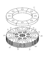
- FIG. 2 is an exploded perspective view for explaining the rotor in one embodiment.
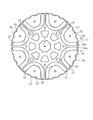
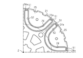
- FIG. 3 is a plan view for explaining the rotor in one embodiment.
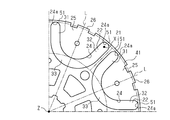
- FIG. 4 is a partially enlarged plan view for explaining the rotor in one embodiment.
- FIG. 5 is a partially enlarged plan view for explaining the rotor core in one embodiment.
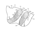
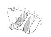
- FIG. 6 is a partially enlarged perspective view for explaining the rotor core in one embodiment.
- FIG. 7 is a partially enlarged plan view for explaining a rotor core in another example.
- FIG. 8 is a partially enlarged perspective view for explaining a rotor core in another example.
- FIG. 9 is a partially enlarged perspective view for explaining a rotor core in another example.
- the rotary electric machine M of the present embodiment is an embedded magnet type brushless motor, which is a motor for a position control device arranged in a vehicle engine room, specifically, valve timing connected to the engine. It is a motor used for a variable device.
- the rotary electric machine M has a motor case 1.
- the motor case 1 has a tubular front housing 2 made of a magnetic material formed in a covered tubular shape, and an end frame 3 made of aluminum (non-magnetic material) that closes the opening of the tubular front housing 2. ing.
- the rotary electric machine M includes a stator 5 fixed to the inner peripheral surface of the tubular front housing 2, and an embedded magnet type rotor 7 including a rotary shaft 6 arranged inside the stator 5.
- the rotating shaft 6 is formed by a bearing 8 accommodated and fixed in a bearing holding portion 2a formed in the tubular front housing 2 and a bearing 9 accommodated and fixed in a bearing holding portion 3a formed in the end frame 3. , It is rotatably supported with respect to the motor case 1.
- a magnetic sensor 10 such as a Hall IC is fixed to the axial inner side surface 3b of the end frame 3.
- the tip of the rotating shaft 6 protrudes from the tubular front housing 2. Then, the rotary drive of the rotary shaft 6 appropriately changes the valve timing according to the operating state, that is, the relative rotational phase of the camshaft with respect to the crankshaft of the engine.
- a stator 5 is fixed to the inner peripheral surface of the tubular front housing 2.
- the stator 5 has a cylindrical stator core 11, and the outer peripheral surface of the stator core 11 is fixed to the inner surface of the tubular front housing 2.
- a plurality of teeth 12 are formed inside the stator core 11 along the axial direction, and are arranged at equal pitches in the circumferential direction. The plurality of teeth 12 are formed so as to extend inward in the radial direction.
- a three-phase winding 15 is wound around each tooth 12 via an insulator 13. Then, when a three-phase drive current is supplied to these windings 15, a rotating magnetic field is generated in the stator 5, and the rotor 7 is rotated in the forward and reverse directions.
- the rotor 7 includes the rotating shaft 6, a substantially cylindrical rotor core 21 into which the rotating shaft 6 is fitted in the center, and a plurality of (8 in this embodiment) permanent magnets 22 embedded inside the rotor core 21. It has.
- the rotor core 21 is configured by laminating a plurality of electromagnetic steel sheets 23, which are magnetic metal materials, in the axial direction.
- the rotor core 21 has a magnet accommodating hole 24 for accommodating the permanent magnet 22.
- a plurality of magnet accommodating holes 24 (8 in this embodiment) are provided at equal intervals in the circumferential direction of the rotor core 21.
- Each magnet accommodating hole 24 has a substantially U-shaped continuous folded shape that is convex inward in the radial direction, and has the same shape as each other.
- the permanent magnet 22 is made of a bonded magnet formed by molding and solidifying a magnet material in which magnet powder is mixed with resin. That is, in the permanent magnet 22, the magnet accommodating hole 24 of the rotor core 21 is molded, and the magnet material before solidification is filled in the magnet accommodating hole 24 without a gap by injection molding, and is solidified in the magnet accommodating hole 24 after filling. It is configured. Therefore, the hole shape of the magnet accommodating hole 24 matches the outer shape of the permanent magnet 22.
- the magnet powder used for the permanent magnet 22 of the present embodiment for example, a sumalium iron nitrogen (SmFeN) magnet is used, but other rare earth magnets or the like may be used.
- the permanent magnet 22 solidified in the magnet accommodating hole 24 of the rotor core 21 is magnetized from the outside of the rotor core 21 by using a magnetizing device (not shown) so as to function as an original magnet.
- the permanent magnets 22 are magnetized so as to alternately have different poles in the circumferential direction of the rotor core 21. Further, the permanent magnet 22 is magnetized in its own thickness direction.
- the rotor 7 has an 8-pole rotor magnetic pole portion 26 including eight permanent magnets 22 and an outer core portion 25 surrounded by the permanent magnets 22. Each rotor magnetic pole portion 26 functions as an N pole and an S pole, respectively.
- the rotor 7 has a configuration in which both magnet torque and reluctance torque can be obtained from the rotor magnetic pole portion 26 described above.
- the shape of the permanent magnet 22 matches the shape of the magnet accommodating hole 24.
- the permanent magnet 22 when the rotor 7 is viewed from the axial direction, the permanent magnet 22 has a substantially U-shaped continuous folded shape that is convex inward in the radial direction.
- the permanent magnet 22 has a line-symmetrical shape with respect to the circumferential center line L passing through the axial center Z of the rotor 7 and the circumferential center of the permanent magnet 22 itself.
- the permanent magnet 22 has a first straight portion 31 as a straight portion on one side in the circumferential direction (for example, the counterclockwise direction side) and a second straight portion 32 as a straight portion on the other side in the circumferential direction (for example, the clockwise side). And a bent portion 33 that connects the radial inner ends of the first and second straight portions 31 and 32 to form a bent shape.
- the first straight line portion 31 and the second straight line portion 32 extend along the radial direction of the rotor 7, respectively. Specifically, the first straight line portion 31 and the second straight line portion 32 extend parallel to the straight line passing through the axial center Z of the rotor 7, respectively.
- the first straight line portion 31 and the second straight line portion 32 that are adjacent to each other in the permanent magnets 22 that are adjacent to each other in the circumferential direction are parallel to each other.
- the rotor 7 of the present embodiment includes an annular end face magnet 41 in which magnetic poles are arranged so as to repel the outer core portion 25 at a position facing the axial end face of the outer core portion 25.
- the end face magnet 41 is fixed to the axial end faces of the rotor core 21 and the permanent magnet 22 by an adhesive.
- the outer diameter of the end face magnet 41 is set to be equal to or greater than the outermost diameter of the permanent magnet 22 and equal to or less than the outermost diameter of the rotor core 21.
- the outer peripheral position of the end face magnet 41 is arranged between the outermost radial position of the permanent magnet 22 and the outermost radial position of the rotor core 21 when viewed from the axial direction.
- the inner diameter of the end face magnet 41 is set to the innermost inner diameter of the outer core portion 25. In other words, the inner circumference of the end face magnet 41 is arranged at the innermost radial position of the outer core portion 25 when viewed from the axial direction.
- the end face magnet 41 is magnetized in the axial direction and magnetized so as to be alternately different in the circumferential direction.
- the end face magnet 41 is magnetized so that eight permanent magnets 22, which are the same number as the number of the outer core portions 25, are alternately different in the circumferential direction.
- the end face magnet 41 is arranged so that each of its own magnetic poles repels the outer core portion 25, in other words, its own magnetic pole coincides with the magnetic pole of the opposite outer core portion 25.
- the end face magnet 41 is arranged so as to face the magnetic sensor 10 while having a gap, and constitutes a sensor magnet capable of detecting the rotation angle of the rotor 7 by the magnetic sensor 10. ing. That is, the end face magnet 41 also serves as a sensor magnet.
- the distance between the radial outer end portion of the magnet accommodating hole 24 and the outer circumference of the rotor core 21 is in the circumferential direction of the rotor 7. It changes continuously and has a curved shape that approaches the center in the circumferential direction.
- the radial outer end portion 24a of the magnet accommodating hole 24 of the present embodiment has a semicircular shape about the center X of the width of the magnet accommodating hole 24 when viewed from the axial direction.
- the magnet accommodating hole 24 has a shape in which a pair of inner walls accommodating the first straight line portion 31 and the second straight line portion 32 of the permanent magnet 22 are connected by a semicircular shape on the outer side in the radial direction.
- the bridge portion 51 formed outside the radial outer end portion 24a of the magnet accommodating hole 24 in the rotor core 21 is thinner toward the center in the circumferential direction and thicker toward the peripheral end.
- FIGS. 5 and 6 a part of the magnet accommodating hole 24 in the axial direction has a deformed portion 24b having a shape different from that of other parts.
- FIGS. 5 and 6 show a rotor core 21 in which the permanent magnet 22 is not arranged.
- the deformed portion 24b is provided at the center of the magnet accommodating hole 24 in the axial direction.
- the deformed portion 24b is provided at the radial outer end portion 24a of the magnet accommodating hole 24, and is projected inward with respect to other portions.
- the deformed portion 24b of the present embodiment is formed in a semicircular shape so as to project inward from the radial outer end portion 24a of the semicircular shape when viewed from the axial direction. Further, the deformed portion 24b of the present embodiment is provided by laminating a plurality of types of electromagnetic steel sheets 23. That is, the rotor core 21 of the present embodiment is formed by laminating a plurality of electrical steel sheets 23, but the electrical steel sheet 23 corresponds to the first electrical steel sheet 23a having a shape corresponding to the deformed portion 24b and other parts. The rotor core 21 of the present embodiment is formed by laminating them, including the second electromagnetic steel sheet 23b.
- the radial outer end portion 24a of the magnet accommodating hole 24 has a curved shape in which the distance between the radial outer end portion of the magnet accommodating hole 24 and the outer periphery of the rotor core 21 is close to the center in the circumferential direction of the rotor. Therefore, it is possible to suppress damage to the rotor core 21 due to stress concentration at the circumferential end portion of the radial outer end portion 24a of the magnet accommodating hole 24 while suppressing the leakage magnetic flux to a small value. That is, the stress is maximized at the circumferential end portion of the radial outer end portion 24a of the magnet accommodating hole 24, but the bridge portion 51 of the rotor core 21 becomes thick and damaged as the distance from the outer circumference of the rotor core 21 increases.
- the cross-sectional area of the magnetic path of the bridge portion 51 becomes smaller as the distance from the outer periphery of the rotor core 21 becomes shorter, and the magnetic path is passed through the magnetic path.
- the leakage flux can be suppressed to a small value.
- the radial outer end portion 24a of the magnet accommodating hole 24 has a semicircular shape centered on the center X of the width of the magnet accommodating hole 24 when viewed from the axial direction. Therefore, for example, the magnet accommodating hole 24
- the bridge portions 51 are equally thick at both ends in the circumferential direction at the radial outer end portions 24a of 24, and damage is suppressed in a well-balanced manner.
- the permanent magnet 22 can be engaged in the axial direction by the deformed portion 24b, and the permanent magnet 22 can be engaged. It is possible to prevent the magnet from coming off from the magnet accommodating hole 24.
- the permanent magnet 22 is prevented from coming off from the magnet accommodating hole 24 by providing the end face magnet 41 on the axial end surface of the permanent magnet 22.
- the deformed portion 24b is provided at the radial outer end portion 24a of the magnet accommodating hole 24 and is convex with respect to other portions, but the present invention is not limited to this, and other positions are not limited to this. May be provided in other shapes.
- the deformed portion 52 may be provided on the entire circumference of the magnet accommodating hole 24 and may be convex inward with respect to other portions. In this way, it is possible to further prevent the permanent magnet 22 from coming off from the magnet accommodating hole 24.
- the deformed portion 53 may be provided in a part of the magnet accommodating hole 24 and may be recessed with respect to another portion. In this way, the rotor core 21 can be easily manufactured.
- the radial outer end portion 24a of the magnet accommodating hole 24 is formed in a semicircular shape about the center X of the width of the magnet accommodating hole 24.
- the radial outer end portion 24a may have another shape as long as it has a curved shape in which the distance from the outer circumference of the rotor core 21 is close to the center in the circumferential direction.
- the radial outer end portion 24a of the magnet accommodating hole 24 may be formed in another curved shape such as an elliptical shape.
- the deformed portion 24b is provided at the center of the magnet accommodating hole 24 in the axial direction, but the present invention is not limited to this, and the deformed portion 24b may be provided at a position deviated from the center in the axial direction. Further, a plurality of deformed portions may be provided in the axial direction.
- the magnet accommodating hole 24 has a deformed portion 24b having a shape partially different from that of other portions in the axial direction, but the magnet accommodating hole 24 is not limited to this. It does not have to have a deformed portion.
- the rotor 7 includes an end face magnet 41 fixed to the axial end faces of the rotor core 21 and the permanent magnet 22, but the rotor 7 may not be provided with the end face magnet 41.
- the permanent magnet 22 is formed in a shape having a first straight line portion 31, a second straight line portion 32, and a bent portion 33, but the present invention is not limited to this, and the permanent magnet 22 is not limited to this, for example, in the axial direction. It may be formed in a shape in which the whole is curved when viewed from the viewpoint.
- the permanent magnet 22 is composed of a bond magnet formed by using the magnet accommodating hole 24 as a molding die, but the present invention is not limited to this, and for example, the permanent magnet 22 is inserted into the magnet accommodating hole 24 after molding. It may be a sintered magnet that is inserted into the magnet accommodating hole 24 after being sintered. In addition, in order to form the permanent magnet 22 having a shape corresponding to the deformed portion 24b as in the above embodiment, it is preferable to use a bond magnet formed by molding the magnet accommodating hole 24 as a molding die.
- the rotor core 21 is formed by laminating a plurality of electromagnetic steel sheets 23 in the axial direction, but the present invention is not limited to this, and for example, a rotor core 21 formed by sintering magnetic powder, etc. It may have the structure of.
Landscapes
- Engineering & Computer Science (AREA)
- Power Engineering (AREA)
- Permanent Field Magnets Of Synchronous Machinery (AREA)
- Iron Core Of Rotating Electric Machines (AREA)
- Permanent Magnet Type Synchronous Machine (AREA)
Priority Applications (3)
| Application Number | Priority Date | Filing Date | Title |
|---|---|---|---|
| CN202180013819.XA CN115104240B (zh) | 2020-02-17 | 2021-02-16 | 转子 |
| DE112021001075.1T DE112021001075T5 (de) | 2020-02-17 | 2021-02-16 | Rotor |
| US17/889,837 US12218547B2 (en) | 2020-02-17 | 2022-08-17 | Rotor |
Applications Claiming Priority (2)
| Application Number | Priority Date | Filing Date | Title |
|---|---|---|---|
| JP2020-024208 | 2020-02-17 | ||
| JP2020024208A JP7367552B2 (ja) | 2020-02-17 | 2020-02-17 | ロータ |
Related Child Applications (1)
| Application Number | Title | Priority Date | Filing Date |
|---|---|---|---|
| US17/889,837 Continuation US12218547B2 (en) | 2020-02-17 | 2022-08-17 | Rotor |
Publications (1)
| Publication Number | Publication Date |
|---|---|
| WO2021166873A1 true WO2021166873A1 (ja) | 2021-08-26 |
Family
ID=77392103
Family Applications (1)
| Application Number | Title | Priority Date | Filing Date |
|---|---|---|---|
| PCT/JP2021/005604 Ceased WO2021166873A1 (ja) | 2020-02-17 | 2021-02-16 | ロータ |
Country Status (5)
| Country | Link |
|---|---|
| US (1) | US12218547B2 (https=) |
| JP (1) | JP7367552B2 (https=) |
| CN (1) | CN115104240B (https=) |
| DE (1) | DE112021001075T5 (https=) |
| WO (1) | WO2021166873A1 (https=) |
Families Citing this family (2)
| Publication number | Priority date | Publication date | Assignee | Title |
|---|---|---|---|---|
| FR3146247A1 (fr) * | 2023-02-27 | 2024-08-30 | Commissariat à l'Energie Atomique et aux Energies Alternatives | Montage réversible d’aimant permanent dans une machine électrique |
| CN120454351A (zh) * | 2024-02-07 | 2025-08-08 | 台达电子工业股份有限公司 | 聚磁转子结构 |
Citations (4)
| Publication number | Priority date | Publication date | Assignee | Title |
|---|---|---|---|---|
| WO2016042720A1 (ja) * | 2014-09-16 | 2016-03-24 | パナソニックIpマネジメント株式会社 | 電動機 |
| JP2019054659A (ja) * | 2017-09-15 | 2019-04-04 | トヨタ自動車株式会社 | 回転電機 |
| JP2019068655A (ja) * | 2017-10-03 | 2019-04-25 | トヨタ自動車株式会社 | 回転電機のロータ |
| JP2019126102A (ja) * | 2016-05-11 | 2019-07-25 | 三菱電機株式会社 | 回転子および回転電機 |
Family Cites Families (11)
| Publication number | Priority date | Publication date | Assignee | Title |
|---|---|---|---|---|
| JP2002078259A (ja) * | 2000-08-31 | 2002-03-15 | Yamaha Motor Co Ltd | 永久磁石回転子 |
| JP2004357468A (ja) * | 2003-05-30 | 2004-12-16 | Matsushita Electric Ind Co Ltd | 電動機 |
| CN102738929B (zh) * | 2007-11-28 | 2014-08-20 | 阿斯莫有限公司 | 埋入磁铁型电动机 |
| JP2013247783A (ja) * | 2012-05-25 | 2013-12-09 | Jtekt Corp | ロータ及びこれを備えた回転電機 |
| WO2014045445A1 (ja) * | 2012-09-24 | 2014-03-27 | 三菱電機株式会社 | 永久磁石埋込型電動機 |
| JP6025683B2 (ja) | 2013-09-19 | 2016-11-16 | 三菱電機株式会社 | 埋込磁石型モータ |
| WO2015104956A1 (ja) * | 2014-01-08 | 2015-07-16 | 三菱電機株式会社 | 回転電機 |
| CN205123431U (zh) * | 2015-11-05 | 2016-03-30 | 青岛万宝压缩机有限公司 | 一种定子、分装式永磁电动机及全封闭变频制冷压缩机 |
| CN106059142B (zh) * | 2016-06-29 | 2019-02-19 | 苏州爱知科技有限公司 | 一种内置式永磁同步电机的转子结构 |
| JP6950361B2 (ja) | 2017-08-28 | 2021-10-13 | 株式会社デンソー | モータ |
| JP7336946B2 (ja) | 2017-11-02 | 2023-09-01 | カシオ計算機株式会社 | アンテナ装置および時計 |
-
2020
- 2020-02-17 JP JP2020024208A patent/JP7367552B2/ja active Active
-
2021
- 2021-02-16 DE DE112021001075.1T patent/DE112021001075T5/de active Pending
- 2021-02-16 CN CN202180013819.XA patent/CN115104240B/zh active Active
- 2021-02-16 WO PCT/JP2021/005604 patent/WO2021166873A1/ja not_active Ceased
-
2022
- 2022-08-17 US US17/889,837 patent/US12218547B2/en active Active
Patent Citations (4)
| Publication number | Priority date | Publication date | Assignee | Title |
|---|---|---|---|---|
| WO2016042720A1 (ja) * | 2014-09-16 | 2016-03-24 | パナソニックIpマネジメント株式会社 | 電動機 |
| JP2019126102A (ja) * | 2016-05-11 | 2019-07-25 | 三菱電機株式会社 | 回転子および回転電機 |
| JP2019054659A (ja) * | 2017-09-15 | 2019-04-04 | トヨタ自動車株式会社 | 回転電機 |
| JP2019068655A (ja) * | 2017-10-03 | 2019-04-25 | トヨタ自動車株式会社 | 回転電機のロータ |
Also Published As
| Publication number | Publication date |
|---|---|
| CN115104240A (zh) | 2022-09-23 |
| JP7367552B2 (ja) | 2023-10-24 |
| CN115104240B (zh) | 2026-01-13 |
| JP2021129471A (ja) | 2021-09-02 |
| US20220393531A1 (en) | 2022-12-08 |
| DE112021001075T5 (de) | 2022-12-01 |
| US12218547B2 (en) | 2025-02-04 |
Similar Documents
| Publication | Publication Date | Title |
|---|---|---|
| US9780610B2 (en) | Rotor and motor | |
| JPWO2017221341A1 (ja) | コンシクエントポール型の回転子、電動機および空気調和機 | |
| US20150084466A1 (en) | Rotor and motor | |
| JP7263971B2 (ja) | ロータ及びモータ | |
| US12218547B2 (en) | Rotor | |
| JP2010022088A (ja) | 磁石回転型回転電機 | |
| JP5702118B2 (ja) | ロータの構造及びモータ | |
| WO2022080010A1 (ja) | ロータ及び回転電機 | |
| US12519356B2 (en) | Rotor and rotating electric machine | |
| JP7501693B2 (ja) | 回転電機及び回転電機の製造方法 | |
| CN111869067B (zh) | 电动机 | |
| JP7615847B2 (ja) | ロータ及び回転電機 | |
| US20240275242A1 (en) | Rotating electric machine | |
| JP7318556B2 (ja) | ロータ | |
| JP3897567B2 (ja) | アウタロータモータ | |
| JP7006103B2 (ja) | ロータ及びモータ | |
| JP6922153B2 (ja) | ランデル型ロータ及びランデル型モータ | |
| KR102030660B1 (ko) | 동기전동기의 회전자 설계 방법 및 상기 방법으로 설계된 동기전동기의 회전자 | |
| JP6539975B2 (ja) | ランデル型ロータ及びモータ | |
| JP6439281B2 (ja) | ランデル型モータ | |
| JP2026003066A (ja) | ロータ及び回転電機 | |
| CN117337532A (zh) | 转子和旋转电机 | |
| JP2010279157A (ja) | 永久磁石型回転機 | |
| KR20180127713A (ko) | 차량용 모터 | |
| JPH0315259A (ja) | ステッピングモータの構造 |
Legal Events
| Date | Code | Title | Description |
|---|---|---|---|
| 121 | Ep: the epo has been informed by wipo that ep was designated in this application |
Ref document number: 21757746 Country of ref document: EP Kind code of ref document: A1 |
|
| 122 | Ep: pct application non-entry in european phase |
Ref document number: 21757746 Country of ref document: EP Kind code of ref document: A1 |