WO2021157574A1 - 制御装置 - Google Patents
制御装置 Download PDFInfo
- Publication number
- WO2021157574A1 WO2021157574A1 PCT/JP2021/003743 JP2021003743W WO2021157574A1 WO 2021157574 A1 WO2021157574 A1 WO 2021157574A1 JP 2021003743 W JP2021003743 W JP 2021003743W WO 2021157574 A1 WO2021157574 A1 WO 2021157574A1
- Authority
- WO
- WIPO (PCT)
- Prior art keywords
- error
- coordinate system
- node
- control point
- unit
- Prior art date
- Legal status (The legal status is an assumption and is not a legal conclusion. Google has not performed a legal analysis and makes no representation as to the accuracy of the status listed.)
- Ceased
Links
Images























Classifications
-
- G—PHYSICS
- G05—CONTROLLING; REGULATING
- G05B—CONTROL OR REGULATING SYSTEMS IN GENERAL; FUNCTIONAL ELEMENTS OF SUCH SYSTEMS; MONITORING OR TESTING ARRANGEMENTS FOR SUCH SYSTEMS OR ELEMENTS
- G05B19/00—Program-control systems
- G05B19/02—Program-control systems electric
- G05B19/18—Numerical control [NC], i.e. automatically operating machines, in particular machine tools, e.g. in a manufacturing environment, so as to execute positioning, movement or co-ordinated operations by means of program data in numerical form
- G05B19/404—Numerical control [NC], i.e. automatically operating machines, in particular machine tools, e.g. in a manufacturing environment, so as to execute positioning, movement or co-ordinated operations by means of program data in numerical form characterised by control arrangements for compensation, e.g. for backlash, overshoot, tool offset, tool wear, temperature, machine construction errors, load, inertia
-
- B—PERFORMING OPERATIONS; TRANSPORTING
- B25—HAND TOOLS; PORTABLE POWER-DRIVEN TOOLS; MANIPULATORS
- B25J—MANIPULATORS; CHAMBERS PROVIDED WITH MANIPULATION DEVICES
- B25J9/00—Program-controlled manipulators
- B25J9/16—Program controls
- B25J9/1656—Program controls characterised by programming, planning systems for manipulators
- B25J9/1664—Program controls characterised by programming, planning systems for manipulators characterised by motion, path, trajectory planning
-
- G—PHYSICS
- G05—CONTROLLING; REGULATING
- G05B—CONTROL OR REGULATING SYSTEMS IN GENERAL; FUNCTIONAL ELEMENTS OF SUCH SYSTEMS; MONITORING OR TESTING ARRANGEMENTS FOR SUCH SYSTEMS OR ELEMENTS
- G05B2219/00—Program-control systems
- G05B2219/30—Nc systems
- G05B2219/37—Measurements
- G05B2219/37506—Correction of position error
-
- G—PHYSICS
- G05—CONTROLLING; REGULATING
- G05B—CONTROL OR REGULATING SYSTEMS IN GENERAL; FUNCTIONAL ELEMENTS OF SUCH SYSTEMS; MONITORING OR TESTING ARRANGEMENTS FOR SUCH SYSTEMS OR ELEMENTS
- G05B2219/00—Program-control systems
- G05B2219/30—Nc systems
- G05B2219/39—Robotics, robotics to robotics hand
- G05B2219/39444—Display of position, of shape of robot and tool
Definitions
- the present invention relates to a control device.
- a control point to be controlled included in the machine tool or the robot is controlled by using a command value in a program.
- the tool root position is usually set as a control point.
- the tool tip position is set as the control point. Then, control is executed so that these control points move to the coordinate values specified by the command value.
- a numerical control device that controls a machine tool having a straight axis and a rotary axis, and calculates the position correction amount of the straight axis from the translation error and the attitude error depending on the motion of the straight axis.
- a rotation axis-dependent position correction amount calculation means that calculates the position correction amount of the straight axis from the calculation means, a translation error and an attitude error that depend on the motion of the rotation axis, and a part of the attitude error that depends on the motion of the straight axis.
- Rotation axis angle correction amount calculation means that calculates the rotation axis angle correction amount from a part of the posture error that depends on the motion of the rotation axis, and position addition that calculates the position correction amount of the straight axis corresponding to the rotation axis correction amount.
- a technique relating to a numerical control device having a correction amount calculation means is known (see, for example, Patent Document 1).
- a technique for correcting an error in a machine tool having an arbitrary machine configuration by using a graph having a component as a node is desired.
- One aspect of the present disclosure is a control device that expresses and holds a machine configuration to be controlled in a graph format having components as nodes, and controls points and a coordinate system for each node of the graph of the machine configuration.
- the control point coordinate system insertion unit that inserts the An error information storage unit that stores the identifier assigned to the coordinate system, an error node generation unit that converts the machine error into an equivalent error node, and an error node addition that adds the error node in the graph of the machine configuration.
- a control point coordinate system designation unit that specifies one or more sets of control points and coordinate systems by the identifier, and the control point and the coordinates designated by the control point coordinate system designation unit with respect to the unit and the graph of the machine configuration.
- a command value determination unit that determines whether one or more command values commanded in the program correspond to a coordinate value on which coordinate system with respect to which control point by the system, and the coordinate value of the control point is the command. It is a control device including a movement command unit that commands the movement of the control point so as to be a value.
- One aspect of the present disclosure is a control device that expresses and holds a machine configuration to be controlled in a graph format having components as nodes, and controls points and a coordinate system for each node of the graph of the machine configuration.
- a control point coordinate system insertion unit that has An error information storage unit that stores the identifier assigned to the coordinate system, an error node generation unit that converts the machine error into an equivalent error node, and an error node addition that adds the error node in the graph of the machine configuration.
- a control point coordinate system designation unit that specifies one or more sets of control points and coordinate systems by the identifier, and the control point and the coordinates designated by the control point coordinate system designation unit with respect to the unit and the graph of the machine configuration.
- a command value determination unit that determines whether one or more command values commanded in the program correspond to a coordinate value on which coordinate system with respect to which control point by the system, and the coordinate value of the control point is the command. It is a control device including a movement command unit that commands the movement of the control point so as to be a value.
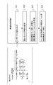
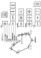
- FIG. 1 shows a configuration example of the control device 100 according to the embodiment of the present invention.
- the control device 100 mainly includes a CPU 11, a ROM 12, a RAM 13, a CMOS 14, interfaces 15, 18, 19, a PMC (programmable machine controller) 16, an I / O unit 17, and an axis control circuit 30 to. 34, servo amplifiers 40 to 44, a spindle control circuit 60, and a spindle amplifier 61 are provided.
- the CPU 11 is a processor that controls the control device 100 as a whole.
- the CPU 11 reads the system program stored in the ROM 12 via the bus 20 and controls the entire control device 100 according to the system program.
- the RAM 13 stores temporary calculation data, display data, and various data input by the operator via the display / MDI unit 70.
- the CMOS memory 14 is configured as a non-volatile memory that is backed up by a battery (not shown) and that retains its storage state even when the power of the control device 100 is turned off.
- the CMOS memory 14 stores a machining program read via the interface 15, a machining program input via the display / MDI unit 70, and the like.
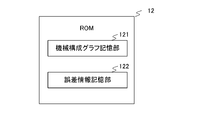
- the ROM 12 includes a machine configuration graph storage unit 141 and an error information storage unit 142.
- FIG. 2 shows the configuration of the ROM 12.
- the machine configuration graph storage unit 141 stores a graph-type machine configuration generated by the graph generation unit 111, which will be described later, that is, the “machine configuration tree” in the present embodiment.
- the error information storage unit 142 stores information related to the machine error in the industrial machine as the control target and an identifier assigned to the coordinate system in which the machine error is observed. This identifier is assigned by the identifier allocation unit 114, which will be described later. The function related to the input / output of information between the error information storage unit 142 and other components provided in the CPU 11 will be described later in the description of the CPU 11.
- machining programs such as a machining program for executing the present invention can be input via the interface 15 and the display / MDI unit 70 and stored in the CMOS memory 14.
- the interface 15 enables connection between the control device 100 and an external device 72 such as an adapter. Machining programs, various parameters, etc. are read from the external device 72 side. Further, the machining program edited in the control device 100 can be stored in the external storage means via the external device 72.
- the PMC (programmable machine controller) 16 is a sequence program built in the control device 100, and sends a signal to an auxiliary device of an industrial machine (for example, an actuator such as a robot hand for changing tools) via an I / O unit 17. Output and control. Further, after receiving signals from various switches of the operation panel provided in the main body of the industrial machine and performing necessary signal processing, the signals are passed to the CPU 11.
- the display / MDI unit 70 is a manual data input device equipped with a display, a keyboard, and the like.
- the interface 18 receives commands and data from the keyboard of the display / MDI unit 70 and passes them to the CPU 11.
- the interface 19 is connected to an operation panel 71 provided with a manual pulse generator or the like.
- the axis control circuits 30 to 34 of each axis receive the movement command amount of each axis from the CPU 11 and output the command of each axis to the servo amplifiers 40 to 44.
- the servo amplifiers 40 to 44 receive this command and drive the servo motors 50 to 54 of each axis.
- the servomotors 50 to 54 of each axis have a built-in position / speed detector, and the position / speed feedback signal from the position / speed detector is fed back to the axis control circuits 30 to 34 to perform position / speed feedback control. conduct. In the block diagram, the position / velocity feedback is omitted.
- the spindle control circuit 60 receives a spindle rotation command to an industrial machine and outputs a spindle speed signal to the spindle amplifier 61. In response to this spindle speed signal, the spindle amplifier 61 rotates the spindle motor 62 of the machine tool at the commanded rotation speed to drive the tool.
- a pulse encoder 63 is coupled to the spindle motor 62 with a gear, a belt, or the like.
- the pulse encoder 63 outputs a feedback pulse in synchronization with the rotation of the spindle.
- the feedback pulse is read by the CPU 11 via the bus 20.
- FIG. 43 is a functional block diagram showing a function in which the CPU 11 reads a system program and an application program stored in the ROM 12 via the bus 20 and realizes the system program and the application program according to the system program and the application program.
- the CPU 11 includes a graph generation unit 111, a control point coordinate system insertion unit 113, an identifier allocation unit 114, an error node generation unit 115, a control point coordinate system designation unit 116, a command value determination unit 117, and a movement command unit. It is equipped with 118.
- the graph generation unit 111 generates the machine configuration to be controlled in a graph format. The detailed operation will be described in detail in "2. Generation of mechanical building” below.
- the graph generation unit 111 includes an error node addition unit 112.
- the function of the error node addition unit 112 will be described later.
- the control point coordinate system insertion unit 113 inserts the control point and the coordinate system into the graph of the machine configuration.
- the identifier assigning unit 114 assigns an identifier to each of the control point and the coordinate system.
- the detailed operation of the control point coordinate system insertion unit 113 and the identifier assignment unit 114 will be described in detail in the following "3. Abstraction of command address” to "8. Derivation of coordinate system from machine configuration tree".
- the error node generation unit 115 converts the mechanical error stored in the error information storage unit 142 into a value relative to the error node insertion position.
- the error node converted by the error node generation unit 115 is added to the machine configuration generated by the error node addition unit 112 in a graph format, that is, the "machine configuration tree" in the present embodiment.
- the control point coordinate system designation unit 116 designates the control point and the coordinate system by the above identifier. Specifically, the control point coordinate system designation unit 116 uses, for example, a command in a program, parameter setting, screen operation, or an input value from an input means to the control device 100 to control the above-mentioned control points and coordinates. Specify the system.
- the command value determination unit 117 determines whether the command value in the program is a coordinate value on which coordinate system with respect to which control point. The detailed operation of the control point coordinate system designation unit 116 and the command value determination unit 117 will be described in detail in the following "3. Abstraction of command address" to "8. Derivation of coordinate system from machine configuration tree".
- the movement command unit 118 commands the movement of the control point so that the coordinate value of the control point becomes the command value in the program.
- the detailed operation of the movement command unit 118 will be described in detail in "9. Movement pulse generation method" below. Further, FIG. 4 shows a configuration example of the movement command unit 118.
- the movement command unit 118 includes a simultaneous equation generation unit 181, a simultaneous equation solving unit 182, and a movement pulse generation unit 183.
- the simultaneous equation generation unit 181 obtains the first coordinate conversion formula of the command value from the designated coordinate system and the graph of the machine configuration by the method described in "9. Moving pulse generation method” below, and also designates it.
- the second coordinate conversion equation of the control point is obtained from the obtained control point and the graph of the machine configuration, and a multidimensional multiple-order simultaneous equation that defines that the first coordinate conversion equation and the second coordinate conversion equation are equal is generated.
- the simultaneous equation solving unit 182 finds the solution of the above-mentioned multiple-dimensional simultaneous equations.
- the moving pulse generation unit 183 uses the solution generated by the simultaneous equation solving unit 182 to generate a moving pulse to be used for the movement command.
- the control device 100 first generates a graph showing a mechanical configuration.
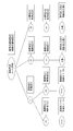
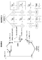
- a generation method for generating a machine constituent tree will be described in detail with reference to FIGS. 5 to 8.
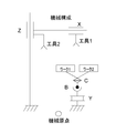
- a method of generating a machine configuration tree expressing the configuration of the machine shown in FIG. 5 will be described.
- the X-axis is set perpendicular to the Z-axis
- the tool 1 is installed on the X-axis
- the tool 2 is installed on the Z-axis.
- the B-axis is set on the Y-axis
- the C-axis is set on the B-axis
- the work 1 and the work 2 are installed on the C-axis.
- the method of expressing this machine structure as a machine structure tree is as follows.
- each node of the machine configuration tree is not limited to the above information, for example, an identifier (name), an identifier of its own parent node, an identifier of all child nodes having its own parent, and an offset relative to the parent node ( Crossover offset), relative coordinate value with respect to the parent node, relative movement direction with respect to the parent node (unit vector), node type (straight line axis / rotation axis / unit (described later) / control point / coordinate system / origin, etc.), physical axis number, It may or may not have information related to the conversion formula between the Cartesian coordinate system and the physical coordinate system.
- each node of the machine configuration tree may or may not have the information necessary for the node itself to be a control point or a coordinate system.
- the information required to be a control point or a coordinate system will be described in detail later, but is, for example, information such as offset, attitude matrix, and whether or not to add movement or offset, and these may or may not be included. You may.
- the embodiment of the control point coordinate system designation unit which will be described later, differs depending on whether or not the node itself has the information necessary for being a control point or a coordinate system. If the node does not have the necessary information, the necessary information can be given to the node by the control point coordinate system insertion unit and the control point coordinate system identifier assignment unit, which will be described later.
- FIG. 8 shows a generalized flowchart of the above-mentioned machine configuration tree generation method, particularly the method of setting each value to each node.
- step S11 the graph generation unit 111 receives the value of the parameter set for the node.
- step S12 when the set parameter item is "own parent node" (S12: YES), the process proceeds to step S13. If it is not the "own parent node” (S12: NO), the process proceeds to step S17.
- step S13 if the parent node has already been set for the node for which the parameter is set (S13: YES), the process proceeds to step S14. If the parent node is not set (S13: NO), the process proceeds to step S15.
- step S14 the graph generation unit 111 deletes its own identifier from the "child node" item of the current parent node of the node for which the parameter is set, and updates the machine configuration tree.
- step S15 the graph generation unit 111 sets a value in the corresponding item of the node for which the parameter is set.
- step S16 the graph generation unit 111 adds its own identifier to the item of "child node" for the parent node, updates the machine configuration tree, and then ends the flow.
- step S17 the graph generation unit 111 ends the flow after setting a value in the corresponding item of the node for which the parameter is set.
- the parent-child relationship means, for example, as shown in FIG. 9A, when there are two rotation axis nodes 104 and 105, the change in the coordinate value of one node 104 is the geometrical state of the other node 105 (typically). Is a relationship that has a one-sided effect on (position / posture).
- the nodes 104 and 105 are referred to as having a parent-child relationship
- the node 104 is referred to as a parent
- the node 105 is referred to as a child.
- FIG. 9A when there are two rotation axis nodes 104 and 105, the change in the coordinate value of one node 104 is the geometrical state of the other node 105 (typically). Is a relationship that has a one-sided effect on (position / posture).
- the nodes 104 and 105 are referred to as having a parent-child relationship
- the node 104 is referred to as a parent
- the node 105 is referred to as
- the unit has two connection points 110 and 120 as shown in FIG. 10A, and when the unit is inserted into the machine configuration tree as shown in FIG. 10B, the parent node has the connection point 120 as shown in FIG. 10C. And the child node is connected to the connection point 110.
- the unit also has a conversion matrix from the connection point 120 to the connection point 110. This transformation matrix is represented by the coordinate values of each node included in the unit. For example, in the case of a machine configuration as shown in FIG.
- the unit representing this mechanical configuration has an homogeneous transformation matrix such as T in the above mathematical formula [Equation 1].
- the homogeneous matrix is a 4 ⁇ 4 matrix that can collectively express the position and posture as in the formula of [Equation 2] below.
- a unit in which a plurality of nodes are grouped into one may be defined in advance and configured in the machine configuration tree. ..
- FIG. 12A shows an example of a flow when the numerical control device reads a script originally written by the user.
- the control device 100 reads the script defined by the user.
- the control device 100 analyzes the content of the read script and newly defines the unit.
- the control device 100 newly registers the newly defined unit as a component that can be inserted into the machine configuration graph.
- the user can insert the registered unique unit (MyUnit in the example of FIG. 12B) into the machine configuration tree.
- the numerical control device may read the script written by the user and analyze the contents thereof to newly define the unit and use it to configure the unit in the machine configuration tree.
- FIG. 12B shows an example in which the newly defined unique unit MyUnit is inserted into the machine configuration tree by the script described in FIG. 12A.
- the graph of the machine configuration can include a unit in which a plurality of axes are grouped into one as a component.
- the above machine configuration tree can be graphically displayed on the display 70 as shown in FIG. 13A, and can be easily set on the display 70 using a graphical user interface (GUI).
- GUI graphical user interface
- nodes can be arranged by drag and drop operation as shown in FIG. 13B
- parent-child relationships between nodes can be set by drag operation as shown in FIG. 13C
- a setting menu is opened by mouse click operation as shown in FIG. 13D. You can set the attributes of.
- the parent-child relationships between the components are also diverse, but usually, numerical control devices do not have information on the parent-child relationships between the components. Controls that require such information are not possible.
- the numerical control device can control machine tools and robots having various machine configurations by using the above-mentioned machine structure tree or a data generation method having a machine structure tree-like data structure. Convenience is improved.
- the user can intuitively set the machine configuration tree in the numerical control device by using the graphical user interface (GUI).
- GUI graphical user interface
- each axis is given an axis name.
- a movement is commanded by using a combination of an axis name and a coordinate value of a movement destination or a numerical value meaning a movement amount.
- the arc path is realized by moving the rotation axis C of the rotary table by 180 degrees, but in the case of 217, the arc path is realized by issuing an arc interpolation command by the linear axis XY.
- the program is different, such as realizing.
- the addresses that can be commanded were determined for each G-code modal, and when the modal changed, it was necessary to change the command address accordingly.
- a command is given by each rotation axis address (for example, addresses A, B, C) in the type 1 mode, and a tool posture vector (for example, in the type 2 mode).
- Addresses that can be commanded are determined during each mode, such as commands with addresses I, J, K). Therefore, for example, it was not possible to give a command with addresses I, J, K during the type 1 mode, or conversely, give a command with the rotation axis addresses A, B, C during the type 2 mode.
- an abstract address that defines the position, orientation, etc. of a certain control point in a certain coordinate system is used instead of the axis name.
- a command is given as shown in 218 of FIG. 15 to define the address.
- addresses ⁇ and ⁇ suitable for a predefined identifier (identifier L1 representing the first linear axis position and identifier L2 representing the second linear axis position) are assigned regardless of the actual axis name in the machine configuration.
- the address ⁇ is defined as the first linear axis position of the Cartesian coordinate system
- the address ⁇ is defined as the second linear axis position of the Cartesian coordinate system.
- each address representing the tool posture vector may be defined. good.
- a suitable address is substituted for the identifiers R1 and R2 representing the first and second rotation axis positions defined in advance regardless of the actual axis name, and the address representing each rotation axis position is defined. May be good. If these are not defined in the program, the default address set by the parameter in the control device 100 is defined as an address representing the abstract meaning of each of the first linear axis position, the second linear axis position, and the like. After that, as shown in 219 of FIG.
- an arbitrary address assigned to the identifier defined in advance for each meaning can be used regardless of the axis name included in the graph of the machine configuration.
- the above "meaning” includes the position of the control point, the posture of the control point, and the angular position of the rotation axis that determines the posture.
- each node of the machine configuration graph can have information necessary for itself to become a control point or a coordinate system, but it may not have it. .. If the node does not have the information necessary to become a control point or coordinate system, specify various positions on the machine configuration as control points and set the coordinate system of various points on the machine configuration. Therefore, the following method is carried out using the mechanical constituent tree generated in the above "2. Generation of mechanical constituent tree”.
- the X1 axis is set perpendicular to the Z1 axis, and the tool 1 is installed on the X1 axis.
- the X2 axis is set perpendicular to the Z2 axis, and the tool 2 is installed on the X2 axis.
- the C1 axis and the C2 axis are set in parallel on the C axis, and the work 1 and the work 2 are installed on each of the C1 axis and the C2 axis.
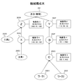
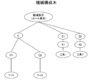
- this machine structure is represented by a machine structure tree, it becomes the machine structure tree shown in FIG. 16B.
- the coordinate system and control points are automatically set for each of the machine origin, C axis, C1 axis, C2 axis, work 1 and work 2. insert. This is performed not only for the table but also for all of the series of nodes connected from each tool to the machine origin, that is, the X1 axis, the X2 axis, the Z1 axis, the Z2 axis, the tool 1, and the tool 2.
- control points and coordinate systems corresponding to each of the nodes constituting the machine constituent tree are automatically inserted. Normally, when machining, a coordinate system and a tool are specified as control points for the work.
- each control point and coordinate system has an offset. Therefore, it is possible to set a point away from the node center as a control point or the origin of the coordinate system.
- each control point and coordinate system has a posture matrix. This posture matrix represents the posture (direction, inclination) of the control point in the case of the posture matrix of the control points, and represents the posture of the coordinate system in the case of the posture matrix of the coordinate system.
- the offset and attitude matrices are represented in a form associated with the corresponding nodes.
- each control point and coordinate system has information on whether or not to take into account the "movement" and "crossing offset" of the nodes existing on the path to the root of the machine constituent tree, and set them. can.
- FIG. 20 shows a generalized flowchart of the above method of automatically inserting control points.
- this flowchart includes chart A and chart B, and as will be described later, chart B is executed in the middle of chart A.
- step S31 the graph generation unit 111 sets the machine constituent tree.
- step S32 chart B is executed and the flow of chart A is terminated.
- step S41 of the chart B if the node has already inserted the control point / coordinate system (S41: YES), the node ends the flow. If the control point / coordinate system has not been inserted into the node (S41: NO), the process proceeds to step S42.
- step S43 if the nth child node exists in the node (S43: YES), the process proceeds to step S44. If the nth child node does not exist in the node (S43: NO), the process proceeds to step S46.
- step S44 the chart B itself is recursively executed for the nth child node.
- step S46 one variable n is popped, and the flow of chart B ends.
- the control point coordinate system insertion unit 113 inserts the control point and the coordinate system as nodes into each node of the graph of the machine configuration.
- the control point coordinate system insertion unit 113 is used for each node in the graph of the machine configuration.
- An embodiment in which a control point and a coordinate system are provided as information is also possible.
- the graph generation unit has the information necessary for the machine configuration tree (each node is a control point or a coordinate system) as shown in FIG. It is also possible to generate a mechanical construction tree). In this case, since the machine constituent tree already has information as a control point or a coordinate system, the control point coordinate system insertion part is not always necessary.
- a route is defined as an arrangement of nodes existing between a certain node in a machine configuration tree.
- the path p1 from the node Z1 to the control point [tool 1] is represented as follows.
- the starting point x 1 in the above route is the route.
- Control points represented by this route the homogeneous matrix M C of the position and orientation relative to the root, Is calculated by However, the meanings of the symbols are as follows.
- S Homogeneous transformation matrix by each node
- N Number of a series of nodes from the root of the machine configuration tree to the control point
- M [ctrl] A homogeneous matrix of offsets and attitudes relative to the parent node of the control point, and is defined from the offset vector and attitude matrix defined at the control points according to the formula of [Equation 2]
- a xi The cross offset of the node xi is added (1), not added (0)
- b xi The movement of the node xi is added (1), not added (0);
- a xi and b xi are information that can be specified when the control point is specified, and the details will be described later in [8. Customization of the coordinate system derived from the machine configuration tree] will be explained
- the homogeneous transformation matrix S changes depending on the node type (straight line axis / rotation axis / unit / control point / coordinate system, etc.) and is represented as follows.
- the meanings of the symbols are as follows.
- x i coordinate value of the node xi; ofs xi : Offset vector relative to the parent node of node xi;
- v xi Movement direction vector of node xi;
- T (0) Identity matrix (non-transformation matrix);
- T (1) Homogeneous transformation matrix from the connection point 120 defined in the unit node to the connection point 110;
- the unit conversion homologous matrix is, for example, a homologous conversion matrix defined for each unit such as T in the mathematical expression of [Equation 1] as described above.
- the homologous transformation matrix S is an identity matrix.
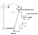
- command point position and command point attitude calculation method As shown in FIG. 24, when the command position vector pos W and the command posture matrix mat W are specified as the command values on a certain designated coordinate system, the position and posture of the command values with respect to the root of the machine constituent tree are represented.
- the homogeneous matrix MM is calculated by the following formula.
- the homogeneous matrix M w of the command value is defined as follows. Also, it considered similarly to the case of the control point, and the path p 3 to a coordinate system that is the root of the machine structure in the tree is as follows. As a result, the homogeneous matrix MM becomes Is calculated by However, the meanings of the symbols are as follows.
- S Homogeneous transformation matrix by each node; L: Number of a series of nodes connected from the root of the machine configuration tree to the coordinate system; M [cord] : An homogeneous matrix of offsets and attitudes relative to the parent node of the coordinate system, which is defined from the offset vector and attitude matrix defined in the coordinate system according to the formula of [Equation 2]; a xi : The cross offset of the node xi is added (1), not added (0); b xi : The movement of the node xi is added (1), not added (0); a xi and b xi are information that can be specified when specifying the coordinate system, and the details will be described later in [8. Customization of the coordinate system derived from the machine configuration tree] will be explained. Further, the homogeneous transformation matrix S is the same as that described using the mathematical formulas of [Equation 6] to [Equation 8].
- FIG. 25 shows an example of a method of designating the coordinate system in the program.
- the command illustrated in FIG. 25 is a sentence example in which the first half specifies a coordinate system and the second half specifies a control point.
- FIG. 25 will be repeated, but the command contents of each line in the program will be described.
- the node "work 1" is designated as the coordinate system by "G54.9 P ⁇ work 1>;" on the first line.
- another identifier "WORK1” is set in the node "work 1”.
- the node "work 1” is designated as the coordinate system by another identifier "WORK1” by "G54.9 P ⁇ WORK1>;” on the third line.
- the coordinate system crossing offset of the node “C1” is set by "G54.7 P ⁇ C1>X_Y_Z_;" on the fourth line.
- the coordinate system attitude matrix of the node “C1” is set in Roll / Pitch / Yaw by "G54.6 P ⁇ C1>I_J_K_;" on the 5th line.
- “G54.9 P ⁇ C1>;” on the sixth line specifies the node “C1” as the coordinate system, and the above-mentioned cross offset and attitude matrix are added.
- the node “tool 1” is designated as a control point by "G43.9 ⁇ tool 1>;” on the 7th line.
- G43.8 P ⁇ tool 1> ⁇ TOOL1>; on the 8th line, another identifier "TOOL1" is set in the node "tool 1".
- the node "tool 1" is designated as a control point by another identifier "TOOL1" by "G43.9 P ⁇ TOOL1>;” on the 9th line.
- the control point crossing offset of the node “B1” is set by "G43.7 P ⁇ B1>X_Y_Z_;” on the 10th line.
- the control point attitude matrix of the node “B1” is set in Roll / Pitch / Yaw by "G43.6 P ⁇ B1>I_J_K_;" on the 11th line.
- the node “B1” is designated as a control point, and the above-mentioned cross offset and attitude matrix are added.
- FIG. 26 shows an example of a method of specifying the control points and the coordinate system inserted into the machine configuration tree in the program by the above "4. Automatic insertion of the control points and the coordinate system".
- the command illustrated in FIG. 26 is a sentence example in which the first half specifies a coordinate system and the second half specifies a control point.
- the description of FIG. 26 will be repeated, but the command contents of each line in the program will be described.
- the coordinate system [work 1] is specified by "G54.9 ⁇ coordinate system [work 1]>;" on the first line. According to the second line "G54.8 P ⁇ coordinate system [work 1]> ⁇ WORK1>;", the identifier "WORK1” is set in the coordinate system [work 1].
- the coordinate system [work 1] is specified by another identifier "WORK1” by “G54.9 P ⁇ WORK1>;” on the third line.
- the crossing offset of the coordinate system [C1] is set by "G54.7 P ⁇ coordinate system [C1]>X_Y_Z_;" on the fourth line.
- the attitude matrix of the coordinate system [C1] is set in Roll / Pitch / Yaw by "G54.6 P ⁇ coordinate system [C1]>I_J_K_;" on the fifth line.
- the coordinate system [C1] is specified by "G54.9 P ⁇ coordinate system [C1]>;” on the sixth line, and the above-mentioned cross offset and attitude matrix are added.
- the control point [tool 1] is specified by "G54.9 ⁇ control point [tool 1]>;” on the 7th line.
- the identifier "TOOL1" is set at the control point [tool 1] by "G54.8 P ⁇ control point [tool 1]> ⁇ TOOL1>;" on the 8th line.
- the control point [tool 1] is designated by another identifier "TOOL1" by "G54.9 P ⁇ TOOL1>;” on the 9th line.
- the crossing offset of the control point [B1] is set by "G54.7 P ⁇ control point [B1]>X_Y_Z_;” on the 10th line.
- the attitude matrix of the control point [B1] is set in Roll / Pitch / Yaw by "G54.6 P ⁇ control point [B1]>I_J_K_;" on the 11th line.
- the control point [B1] is specified by "G54.9 P ⁇ control point [B1]>;" on the 12th line, and the above cross offset is added.
- each G code that specifies the control point and the coordinate system has a separate number, but in FIG. 26, each G code that specifies the control point and the coordinate system can be made common.
- the coordinate system control point insertion unit and the identifier assignment unit are not indispensable for the practice of the present invention, but may be introduced.
- a suitable coordinate system in the machine configuration tree can be selected by a program command, and the command values on the selected coordinate system have been described using the mathematical formulas [Equation 9] to [Equation 11].
- a series of a xi and b xi corresponding to each node in the path p3 are basically calculated as 1 as follows. In this case, all intersection offsets and movements of a series of nodes are taken into account.
- a p3 and b p3 have elements corresponding to each element of the route p3, and can be seen as an accompanying route. Therefore, these are referred to as the accompanying paths a p3 and b p3 of p3 .
- the coordinate system does not rotate only with respect to a specific axis. For example, if you want to turning by C1-axis on the following coordinate system defined by the path p 4 in FIGS. 19A and 19B, easier to use not Limit your As the C1 axis.
- the coordinate system can be customized so as not to be carried only on the C1 axis.
- the accompanying route can be specified by a program command as shown in FIG. 27.
- ac1 of the coordinate system inserted in the work 1 can be specified as 0 by the G254.9P ⁇ work 1> Q ⁇ C1> 0 command.
- the bc1 of the coordinate system inserted in the work 1 can be specified as 0 by the G154.9P ⁇ work 1> Q ⁇ C1> 0 command.
- control points since there are accompanying paths not only in the coordinate system but also in the control points, customized control points can be used by specifying the accompanying paths in the program as well.
- the coordinate system and the control points can be arbitrarily customized by changing the information for defining the coordinate system and the control points.
- the coordinate system and control points can eliminate the effects of specific nodes, specifically the movement and offset of specific nodes.
- the first coordinate conversion formula of the command value is obtained by the method of [Calculation method of command point position and command point attitude].
- the second coordinate conversion formula of the control point is obtained by the method of [Calculation method of control point position and control point attitude].
- a multi-dimensional and multi-order simultaneous equation that defines that the first coordinate conversion equation and the second coordinate conversion equation are equal is obtained.
- the movement pulse used for the movement command is generated by using the solution of the above-mentioned multi-dimensional multiple-order simultaneous equations calculated using, for example, the Gröbner basis.
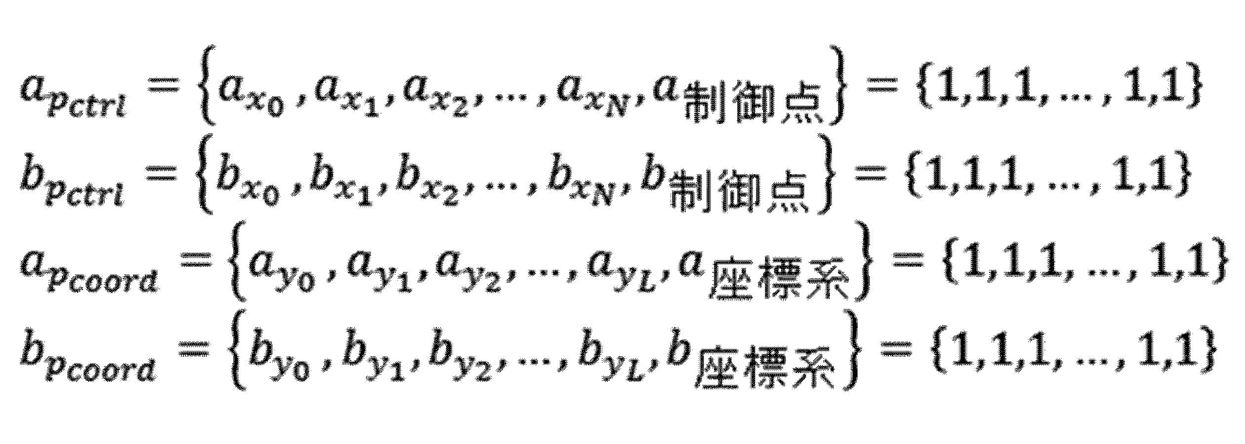
- the axis x2 is set on the axis x1, the axis x3 is set on the axis x2, N nodes are connected in the same manner, and the end thereof is the axis xN. .. Further, it is assumed that a control point is installed on the axis xN.
- the axis y2 is set on the axis y1, the axis y3 is set on the axis y2, L nodes are connected in the same manner, and the end thereof is the axis yL.
- the work is installed on the axis yL.
- xi and yj are node names, but at the same time, the coordinate values of each node are also represented.
- each node is given the offset shown in FIG. 28, the node type (straight line / rotation / unit / control point / coordinate system), the axial direction, the attitude matrix, and the coordinate values.
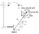
- the homogeneous matrix Mc representing the current position / orientation of the control point with respect to the route (machine origin) is obtained by the following equation.
- the meaning of the symbol is [5. Calculation method of control point position and control point posture], so it is omitted here.
- the homogeneous matrix Mcw representing the current position / orientation of the control point on the designated coordinate system is obtained by the following equation using Mc. From this, the current position vector pos cw of the control point on the designated coordinate system is obtained as follows.
- the next interpolation position vector pos w'in the designated coordinate system is obtained by the following equation using pos w.
- F is a designated moving speed for each interpolation cycle.
- the current tool direction vector vc cw of the control point on the designated coordinate system is obtained as follows assuming that the tool reference direction vector is (0, 0, 1, 0).
- the tool reference direction vector is not limited to the above, and may be changed by a command, parameter setting, or the like.
- next interpolation position vector pose'and the next interpolation tool direction vector vecw' as described above, the following simultaneous equations are established for each of the positions and orientations of the control points.
- the next interpolation position for each axis can be obtained.
- constraint conditions such as not moving some axes or giving command values directly to some axes are appropriately added to the formula of [Equation 23]. It can be dealt with by adding and coalescing. Alternatively, some axes can be dealt with by giving an attribute of an auxiliary axis that normally does not move and moving it only in the vicinity of the singular point for the singular point avoidance operation. Alternatively, it is possible to deal with it by adding an auxiliary control point and instructing it as well.
- a rotation axis in which the tool direction of a control point with respect to a specified coordinate system changes due to a change in coordinate values is called a tool change rotation axis in order to distinguish it from a rotation axis that does not contribute to a change in the tool direction.
- each node of the machine configuration tree has information on whether or not it is a tool change rotation axis.
- each route from the route to the control point / coordinate system is represented by the mathematical formula of [Equation 15], and the list of tool change rotation axis nodes included in each route is the mathematical formula of [Equation 24].
- the order is first and second in order from the one farthest from the root, and then the third and second in order from the tool change rotation axis on the coordinate system side from the root.
- the order of the tool change rotation axis can be defined exactly for any machine construction tree.
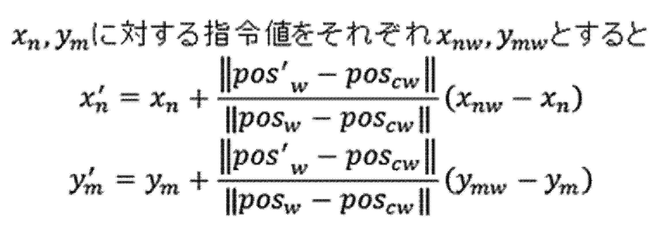
- xn will be referred to as a first tool change rotation axis
- ym will be referred to as a second tool change rotation axis.
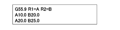
- an identifier R1 representing the first tool change rotation axis and an identifier R2 representing the second tool change rotation axis are used to give a command as shown in FIG. 34.
- next interpolation positions xn'and yn' of the first tool change rotation axis and the second tool change rotation axis can be obtained by the following equations.
- the node coordinate values of the first tool change rotation axis and the second tool change rotation axis are determined, so that the tool direction vector is also determined. Then, since it is not necessary to solve the simultaneous equations for the tool direction vector, it is sufficient to solve the simultaneous equations for the following command positions.
- the coordinate value of a specific node can be directly specified as the command value in the program. This makes it possible to reduce the number of simultaneous types.
- the first embodiment is an embodiment in which an error node related to a three-dimensional rotation error is inserted next to the machine origin in the machine configuration tree.
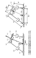
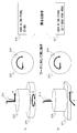
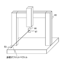
- FIG. 35 is a diagram illustrating a method of actually measuring an error in the machine tool 65.
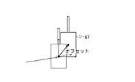
- a mirror 67 is installed at the tip of a tool 66 of a machine tool 65, and a laser interferometer (not shown) irradiates the mirror 67 with a laser to measure an error in the position of the mirror 67.
- the error in the position of the mirror 67 consists of a translation error and a rotation error.
- the translation error is an error related to the deviation of the center position of the mirror 67, and is actually measured as an offset of the center position.
- the rotation error is an error related to the posture of the mirror 67, and is actually measured as a rotation angle around the X axis, a rotation angle around the Y axis, and a rotation angle around the Z axis.
- the translation error and the rotation error are difference values on the machine coordinate system.
- the rotation error matrix representing the rotation error of the mirror 67 the rotation angles a and b around the X-axis, the rotation angle b around the Y-axis, and the rotation angle c around the Z-axis of the mirror 67 are used.
- c is small, it can be roughly calculated by the following formula.
- These translation error vectors and rotation error matrices are stored in the error information storage unit 142 as error information. Further, it is stored in the error information storage unit 142 as a coordinate system in which the machine coordinate system observes the error.
- the error at the mirror position stored in the error information storage unit 142 is converted into the error at the error node insertion position by the error node generation unit 115.
- the error is converted into the error at the machine origin 68 of the machine tool 65.
- the vector from the machine origin 68 to the position of the mirror 67 is referred to here as an “error offset vector”.
- the error offset vector can be calculated from the machine construction tree.
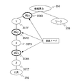
- a node separated by an error offset vector from the node 352 corresponding to the mirror is added as an error node 354 next to the node 353 corresponding to the machine origin. do.
- the translation error at the mirror position is Rotation error at the mirror position Translation error at machine origin position Rotation error at machine origin position Error offset vector
- the error node generation unit 115 converts the error at the mirror position into the error at the machine origin and generates the error node corresponding to the error at the machine origin by using the following equation.
- the above formula is a formula when the movement of the position is calculated first in the coordinate value in the forward kinematics transformation among the positions / postures stored in the nodes of the machine constituent tree. To the formula when the rotation of the posture is calculated first Can be converted with.
- the error node addition unit 112 adds the error node 354 generated by the error node generation unit 115 to the machine configuration tree next to the node 353 corresponding to the machine origin.
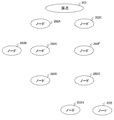
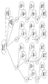
- FIG. 41 shows the machine configuration tree after the error node 354 has been added.
- control device 100 calculates the motor command value using the machine configuration tree to which the error node 354 is added.
- Example 1 it is possible to correct the error even when the cause of the measured error cannot be separated for each axis.
- the second embodiment is an embodiment in which an error node related to a three-dimensional rotation error is inserted at a mirror position in a machine configuration tree.
- the translational error vector and the rotation error matrix are stored in the error information storage unit 142 as error information, and the mirror position stored in the error information storage unit 142.
- the error in is converted into an error at the error node insertion position by the error node generation unit 115.
- the error node generation unit 115 provides two nodes corresponding to the mirror offset. as well as To generate.
- the "mirror offset” is a vector from the center position of the mirror 67 to the root position of the tool 66 as shown in FIG. 42. That is, it is a vector from the position where the error is measured until the error node is inserted, and corresponds to the error offset vector of the above "Example 1".
- the error node addition unit 112 adds the error node 354 generated by the error node generation unit 115 and the two mirror offset nodes 355A and 355B to the machine configuration tree. More specifically, as shown in FIG. 43, two mirror offset nodes 355A and 355B are added next to the node 356 corresponding to the tool, and an error node 354 is placed between the two mirror offset nodes 355A and 355B. to add.
- the node in which these 355A, 354, and 355B are combined corresponds to the error at the error node insertion position 357Z.
- control device 100 calculates the motor command value using the machine configuration tree to which the error node 354 and the two mirror offset nodes 355A and 355B are added.
- the third embodiment is an embodiment in which an error node corresponding to the squareness error of each axis is inserted into one of the error nodes corresponding to each axis on the machine origin side in the machine configuration tree.
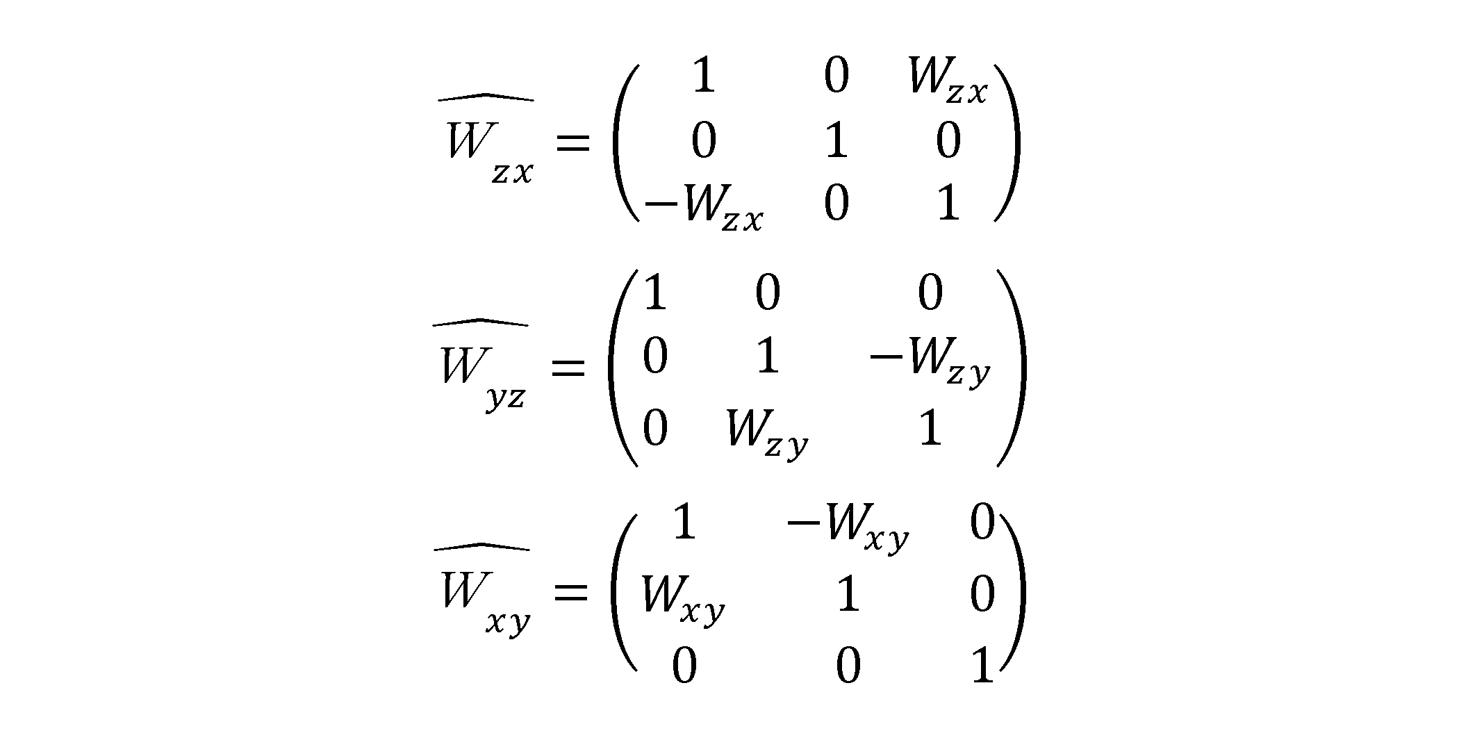
- a ball bar is used to obtain Wzx, which is a squareness error around the ZZ axis, Wyz, which is a squareness error around the YY axis, and squareness error around the XY axis.
- Wxy can be measured.
- the measured information is stored in the error information storage unit 142 as error information.
- the ball bar is a measuring instrument that measures the relative displacement between two balls attached to both ends of a telescopic rod having a built-in displacement meter.
- FIG. 44 shows the squareness error around each axis.
- the error node generation unit 115 converts each squareness error stored in the error information storage unit 142 into a squareness error matrix for each axis by using the following mathematical formula.
- the error node addition unit 112 adds error nodes 354A to 354C, which are squareness error matrices generated by the error node generation unit 115, to the machine configuration tree. More specifically, as shown in FIG. 45, the error node addition unit 112 is provided in the machine configuration tree. The error node 354A corresponding to is added in front of the node 357Z corresponding to the Z axis when viewed from the machine origin. Similarly, the error node addition unit 112 in the machine configuration tree The error node 354B corresponding to is added in front of the node 357Y corresponding to the Y axis when viewed from the machine origin. Similarly, the error node addition unit 112 in the machine configuration tree The error node 354C corresponding to is added in front of the node 357X corresponding to the X axis when viewed from the machine origin.
- control device 100 calculates the motor command value using the machine configuration tree to which the error nodes 354A to 354C are added.
- the error node 354 is inserted immediately before the axis that causes the error, it is possible to generate a machine component tree that most faithfully reproduces the actual machine tool.
- the fourth embodiment is an embodiment in which an error node related to an error measured on the machine tool is inserted into the machine constituent tree.
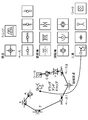
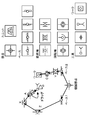
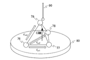
- the artifact 75 as shown in FIG. 46 is prepared.
- the "artifact” is an artificial object having a reference shape for measurement.
- the artifact 75 has a shape in which each of the four spheres 76 to 79 is the apex of the triangular pyramid.
- the true value of the vector from sphere 76 to sphere 77 in the coordinate system on the C-axis node The true value of the vector from sphere 76 to sphere 78 in the coordinate system on the C-axis node, The true value of the vector from sphere 76 to sphere 79 in the coordinate system on the C-axis node, And.
- the artifact 75 is placed on the table 80 provided in the machine tool and measured with the coordinates of the spheres 76 to 79 by the probe 90 attached to the tool tip of the machine tool.
- the "probe” is a measuring instrument that measures the origin, position, posture, etc. of the work installed on the table 80.
- the central axis of the table 80 is referred to as the C axis here.
- the measured value of the vector from the sphere 76 to the sphere 77 obtained from the measured value of the coordinates of the spheres 76 to 79, Measured values of the vector from sphere 76 to sphere 78 in the coordinate system on the C-axis node, Measured values of the vector from sphere 76 to sphere 79 in the coordinate system on the C-axis node, And.
- the error information storage unit 142 stores these true values and measured values as error information.
- the error node generation unit 115 converts each measured value stored in the error information storage unit 142 into a true value by using the following mathematical formula. And generate the error node 354 corresponding to this.
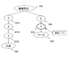
- the error node addition unit 112 adds the error node 354 generated by the error node generation unit 115 to the machine configuration tree. More specifically, as shown in FIG. 48, the error node addition unit 112 is placed between the node 359 corresponding to the work and the node 360 corresponding to the C axis. The error node 354 corresponding to is added.
- control device 100 calculates the motor command value using the machine configuration tree to which the error node 354 is added.
- Example 4 measures the error in the table coordinate system, and the error can be measured by attaching a contact probe instead of the tool. Therefore, an expensive sensor such as a laser interferometer is not required.
- the shape of the artifact does not matter as long as the true value can be known, the workpiece machined by the user is measured with a three-dimensional coordinate measuring machine and corrected as the true value, that is, the result of the inspection process is processed. It can also be used for feeding back to the process, or measuring and correcting the installation position error of the work.
- the control device according to the present embodiment is a control device (for example, the above-mentioned "control device 100") that expresses and holds the machine configuration to be controlled in a graph format in which the constituent elements are nodes, and the machine configuration.
- a control point coordinate system insertion unit (for example, the above-mentioned "control point coordinate system insertion unit 113") that inserts a control point and a coordinate system as a node, the inserted control point, and the said An identifier assigning unit that assigns an identifier to the coordinate system (for example, the above-mentioned "identifier assigning unit 114"), information related to the mechanical error in the controlled object, and an identifier assigned to the coordinate system in which the mechanical error is observed are stored.
- An error information storage unit for example, the above-mentioned "error information storage unit 142”
- an error node generation unit for example, the above-mentioned "error node generation unit 115" that converts the mechanical error into an equivalent error node.
- control point and the coordinate system are set to 1 by the identifier with respect to the error node addition unit (for example, the above “error node addition unit 112”) to which the error node is added and the graph of the machine configuration.
- error node addition unit for example, the above “error node addition unit 112”
- control point coordinate system designation unit for example, the above-mentioned "control point coordinate system designation unit 116" designated by the set or more, the control point designated by the control point coordinate system designation unit, and the coordinate system.
- a command value determination unit that determines whether one or more command values commanded in A movement command unit (for example, the above-mentioned “movement command unit 118”) that commands the movement of the control point is provided.
- control device 100 is a control device (for example, the above-mentioned "control device 100") that expresses and holds the machine configuration to be controlled in a graph format in which the constituent elements are nodes.
- a control point coordinate system insertion unit (for example, the above-mentioned “control point coordinate system insertion unit 113") that gives each node of the graph of the machine configuration a control point and a coordinate system as information, and the inserted control.
- An identifier assigning unit that assigns an identifier to a point and the coordinate system (for example, the above-mentioned "identifier assigning unit 114"), information related to a mechanical error in the controlled object, and an identifier assigned to the coordinate system in which the mechanical error is observed.
- An error information storage unit that stores the above (for example, the above-mentioned "error information storage unit 142") and an error node generation unit that converts the mechanical error into an equivalent error node (for example, the above-mentioned "error node generation unit 115").
- An error node addition unit for adding the error node for example, the above "error node addition unit 112" in the machine configuration graph, and control points and coordinates according to the identifier for the machine configuration graph.
- the control point coordinate system designation unit for example, the above-mentioned "control point coordinate system designation unit 116" that specifies one or more sets of systems, the control point designated by the control point coordinate system designation unit, and the coordinate system.
- a command value determination unit that determines whether one or more command values commanded in the program correspond to a coordinate value on which coordinate system with respect to which control point, and the coordinate value of the control point is the command value. As such, it includes a movement command unit (for example, the above-mentioned “movement command unit 118”) that commands the movement of the control point.
- a movement command unit for example, the above-mentioned “movement command unit 118”
- the present invention is not limited to the above-described embodiments.
- the effects described in the present embodiment merely list the most preferable effects arising from the present invention, and the effects according to the present invention are not limited to those described in the present embodiment.
- the control method by the control device 100 is realized by software.
- the programs constituting the software are installed in the computer (control device 100).
- these programs may be recorded on removable media and distributed to users, or may be distributed by being downloaded to a user's computer via a network. Further, these programs may be provided to the user's computer (control device 100) as a Web service via the network without being downloaded.
Landscapes
- Engineering & Computer Science (AREA)
- Human Computer Interaction (AREA)
- Manufacturing & Machinery (AREA)
- Physics & Mathematics (AREA)
- General Physics & Mathematics (AREA)
- Automation & Control Theory (AREA)
- Robotics (AREA)
- Mechanical Engineering (AREA)
- Numerical Control (AREA)
Abstract
Description
図1には、本発明の実施形態に係る制御装置100の構成例が示されている。制御装置100は、主として、CPU11と、ROM12と、RAM13と、CMOS14と、インタフェース15、18、19と、PMC(プログラマブル・マシン・コントローラ)16と、I/Oユニット17と、軸制御回路30~34と、サーボアンプ40~44と、スピンドル制御回路60と、スピンドルアンプ61とを備える。
なお、誤差情報記憶部142と、CPU11に備わる他の構成要素との情報の入出力に係る機能については、CPU11に係る説明の中で後述する。
識別子割り当て部114は、制御点及び座標系のそれぞれに識別子を割り当てる。
制御点座標系挿入部113及び識別子割り当て部114の詳細な動作については、以下の「3.指令アドレスの抽象化」~「8.機械構成木からの座標系の導出」で詳述する。
誤差ノード生成部115によって変換された誤差ノードは、誤差ノード追加部112によって、機械構成をグラフ形式で生成された機械構成、すなわち本実施形態における「機械構成木」に追加される。
指令値判断部117は、プログラム中の指令値が、どの制御点に対するどの座標系上の座標値か判断する。
制御点座標系指定部116及び指令値判断部117の詳細な動作については、以下の「3.指令アドレスの抽象化」~「8.機械構成木からの座標系の導出」で詳述する。
移動パルス生成部183は、連立方程式求解部182が生成した解を用いて、移動指令に用いる移動パルスを生成する。
本発明の実施形態に係る制御装置100は、最初に、機械構成を表すグラフを生成する。グラフの一例として機械構成木を生成する生成方法について、図5~図8を参照しながら詳述する。
ステップS12において、設定されたパラメータの項目が「自身の親ノード」の場合(S12:YES)には、処理はステップS13に移行する。「自身の親ノード」ではない場合(S12:NO)には、処理はステップS17に移行する。
ここで親子関係とは、例えば図9Aのように、2つの回転軸ノード104、105があったとき、一方のノード104の座標値の変化が、他方のノード105の幾何的状態(典型的には、位置・姿勢)に対して一方的に影響を及ぼすような関係のことである。この場合ノード104、105は親子関係にあると呼び、ノード104を親、ノード105を子と呼ぶ。
しかし、例えば図9Bに示すように、2つの直線軸ノード102、103と4つのフリージョイント101により構成された機械構成においては、ノード102、103の一方の座標値(長さ)が変わることにより、他方の幾何的状態だけでなく、自身の幾何的状態も変わるような、相互に影響を及ぼす機構が存在する。このような場合は、互いに親であり子、すなわち親子関係が双方向であるとみなすことができる。


図12Aは、ユーザが独自に記述したスクリプトを数値制御装置が読み込む際のフローの例を示す。
ステップS21において、制御装置100が、ユーザによって定義されたスクリプトを読み込む。
ステップS22において、制御装置100が、読み込んだスクリプトの内容を解析し、ユニットを新たに定義する。
ステップS23において、制御装置100が、新たに定義したユニットを、機械構成グラフに挿入可能な構成要素として、新たに登録する。
その結果、ステップS24において、ユーザは登録された独自ユニット(図12Bの例においては、MyUnit)を機械構成木に挿入することが可能となる。
図12Bは、図12Aに記載のスクリプトにより、新たに定義された独自ユニットMyUnitが機械構成木に挿入された例を示す。これにより、ユーザの所望の形式のユニットが数値制御装置に予め定義されていなくても、ユーザが独自に定義を追加できるため、利便性が向上する。
上記のように、機械構成木を生成する際には、個々の軸に軸名称を付ける。通常、数値制御装置で使用される加工プログラムにおいては、軸名称と移動先の座標値又は移動量を意味する数値との組み合わせを用いて、移動を指令する。
「2.機械構成木の生成」にて述べたように、機械構成グラフの各ノードは、自身が制御点あるいは座標系となるために必要な情報を持つことができるが、持たないこともできる。ノードが制御点あるいは座標系となるために必要な情報を持たない場合には、機械構成上の様々な位置を、制御点として指定すると共に、機械構成上の様々な箇所の座標系を設定するため、上記の「2.機械構成木の生成」で生成された機械構成木を用いて、以下の方法を実施する。
ステップS31において、グラフ生成部111は、機械構成木を設定する。
ステップS32において、チャートBを実行し、チャートAのフローを終了する。
チャートBのステップS41において、ノードは制御点・座標系を挿入済である場合(S41:YES)には、フローを終了する。ノードに制御点・座標系を挿入済でない場合(S41:NO)には、処理はステップS42に移行する。
図23に示すように、機械構成木のルートに対する、機械構成木中のある制御点の位置・姿勢を表す同次マトリクスをMCとした場合、これは以下のように求められる。



S:各ノードによる同次変換マトリクス;
N:機械構成木のルートから制御点まで連なる一連のノード個数;
M[ctrl]:制御点の親ノードに対する相対オフセット・姿勢の同次マトリクスであり、制御点に定義されたオフセットベクトル・姿勢マトリクスから[数2]の数式に従って定義される;
axi:ノードxiの交叉オフセットを加味する(1)、加味しない(0);
bxi:ノードxiの移動を加味する(1)、加味しない(0);
ここで、axi、bxiは制御点を指定する際に指定することもできる情報で、詳細については後述の〔8.機械構成木から導出した座標系のカスタマイズ〕において説明する。
直線軸の場合

xi:ノードxiの座標値;
ofsxi:ノードxiの親ノードに対する相対オフセットベクトル;
vxi:ノードxiの移動方向ベクトル;
回転軸の場合
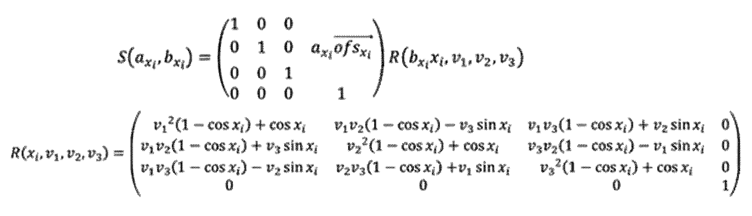
v1:ノードxiの回転軸方向ベクトルの第1成分;
v2:ノードxiの回転軸方向ベクトルの第2成分;
v3:ノードxiの回転軸方向ベクトルの第3成分;
ユニットの場合
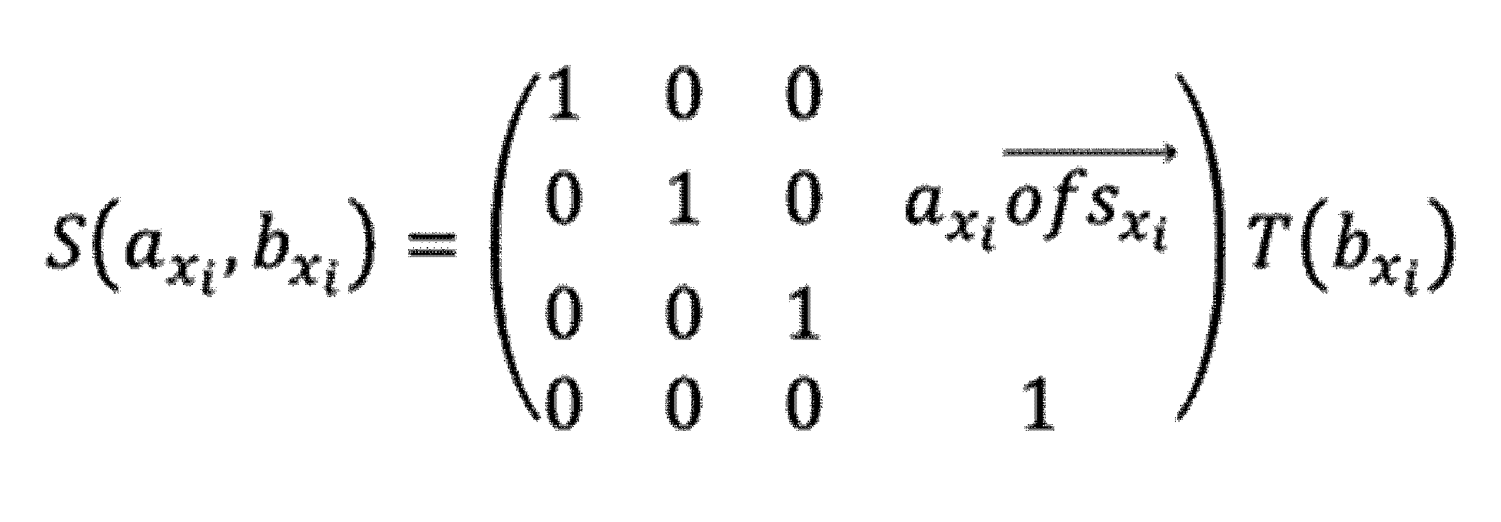
T(0):単位行列(無変換行列);
T(1):ユニットノードに定義された接続点120から接続点110への同次変換マトリクス;
ユニットの変換同次マトリクスについては、先述した通り例えば[数1]の数式中のTのようなユニット毎に定義された同次変換マトリクスである。
また、特に規定が無い場合、同次変換マトリクスSは単位行列とする。
図24に示すように、ある指定座標系上の指令値として、指令位置ベクトルposW、指令姿勢マトリクスmatWが指定されている場合、この指令値の、機械構成木のルートに対する位置姿勢を表す同次マトリクスMMは、以下の式により求められる。
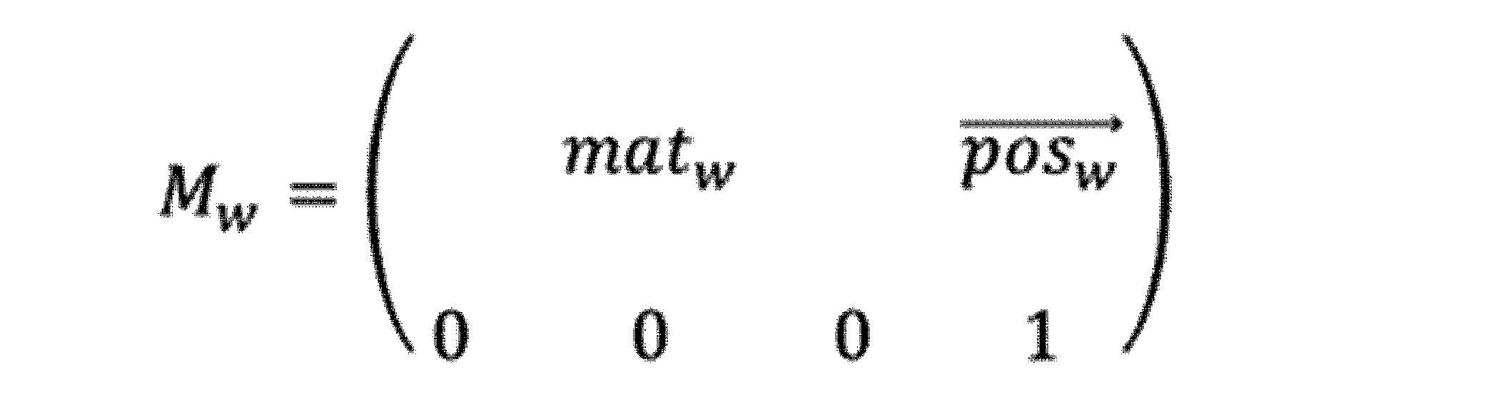


S:各ノードによる同次変換マトリクス;
L:機械構成木のルートから座標系まで連なる一連のノード個数;
M[coord]:座標系の親ノードに対する相対オフセット・姿勢の同次マトリクスであり、座標系に定義されたオフセットベクトル・姿勢マトリクスから[数2]の数式に従って定義される;
axi:ノードxiの交叉オフセットを加味する(1)、加味しない(0);
bxi:ノードxiの移動を加味する(1)、加味しない(0);
axi、bxiは座標系を指定する際に指定することのできる情報で、詳細については後述の〔8.機械構成木から導出した座標系のカスタマイズ〕において説明する。
また、同次変換マトリクスSは[数6]~[数8]の数式を用いて説明したものと同様である。
まず、上記の「2.機械構成木の生成」において、各ノードが制御点あるいは座標系であるために必要な情報を持つように機械構成木が生成された場合に、各ノードを制御点あるいは座標系としてプログラム内で指定する方法の一例を、図25に示す。
2行目の「G54.8 P<ワーク1><WORK1>;」により、ノード「ワーク1」に“WORK1”という別の識別子を設定する。
3行目の「G54.9 P<WORK1>;」により、「WORK1」という別の識別子により、ノード「ワーク1」を座標系として指定する。
4行目の「G54.7 P<C1> X_Y_Z_;」により、ノード「C1」の座標系交叉オフセットを設定する。
5行目の「G54.6 P<C1> I_J_K_;」により、ノード「C1」の座標系姿勢マトリクスをRoll/Pitch/Yawで設定する。
6行目の「G54.9 P<C1>;」により、ノード「C1」を座標系として指定すると共に、上記の交叉オフセット及び姿勢マトリクスが加味される。
7行目の「G43.9 <工具1>;」により、ノード「工具1」を制御点として指定する。
8行目の「G43.8 P<工具1><TOOL1>;」により、ノード「工具1」に「TOOL1」という別の識別子を設定する。
9行目の「G43.9 P<TOOL1>;」により、「TOOL1」という別の識別子により、ノード「工具1」を制御点として指定する。
10行目の「G43.7 P<B1> X_Y_Z_;」により、ノード「B1」の制御点交叉オフセットを設定する。
11行目の「G43.6 P<B1> I_J_K_;」により、ノード「B1」の制御点姿勢マトリクスをRoll/Pitch/Yawで設定する。
12行目の「G43.9 P<B1>;」により、ノード「B1」を制御点として指定する共に、上記の交叉オフセット及び姿勢マトリクスが加味される。
2行目の「G54.8 P<座標系[ワーク1]><WORK1>;」により、座標系[ワーク1]に“WORK1”という識別子を設定する。
3行目の「G54.9 P<WORK1>;」により、“WORK1”という別の識別子により、座標系[ワーク1]を指定する。
4行目の「G54.7 P<座標系[C1]> X_Y_Z_;」により、座標系[C1]の交叉オフセットを設定する。
5行目の「G54.6 P<座標系[C1]> I_J_K_;」により、座標系[C1]の姿勢マトリクスをRoll/Pitch/Yawで設定する。
6行目の「G54.9 P<座標系[C1]>;」により、座標系[C1]を指定すると共に、上記の交叉オフセット及び姿勢マトリクスが加味される。
7行目の「G54.9 <制御点[工具1]>;」により、制御点[工具1]を指定する。
8行目の「G54.8 P<制御点[工具1]><TOOL1>;」により、制御点[工具1]に“TOOL1”という識別子を設定する。
9行目の「G54.9 P<TOOL1>;」により、“TOOL1”という別の識別子により、制御点[工具1]を指定する。
10行目の「G54.7 P<制御点[B1]> X_Y_Z_;」により、制御点[B1]の交叉オフセットを設定する。
11行目の「G54.6 P<制御点[B1]> I_J_K_;」により、制御点[B1]の姿勢マトリクスをRoll/Pitch/Yawで設定する。
12行目の「G54.9 P<制御点[B1]>;」により、制御点[B1]を指定する共に、上記の交叉オフセットが加味される。
上述の通り、機械構成木中の好適な座標系をプログラム指令により選択することができ、選択された座標系上の指令値は、[数9]~[数11]の数式を用いて説明したように機械座標値に変換することができる。この変換において、経路p3中の各ノードに対応する一連のaxi、bxiは基本的には以下のように全て1として計算される。


とりわけ、座標系及び制御点は、特定のノードの影響、具体的には、特定のノードの移動及びオフセットによる影響を除くことが可能である。
次に、本発明の実施形態に係る制御装置100は、〔3.指令アドレスの抽象化〕の方法により指令されたプログラム内の指令値を、〔7.プログラム内における制御点及び座標系の指定方法〕及び〔8.機械構成木から導出した座標系のカスタマイズ〕の方法により指定された座標系上の座標値と解釈し、指定された制御点の座標値が、この指令値となるように制御点を移動させるために必要な移動パルスを生成する。
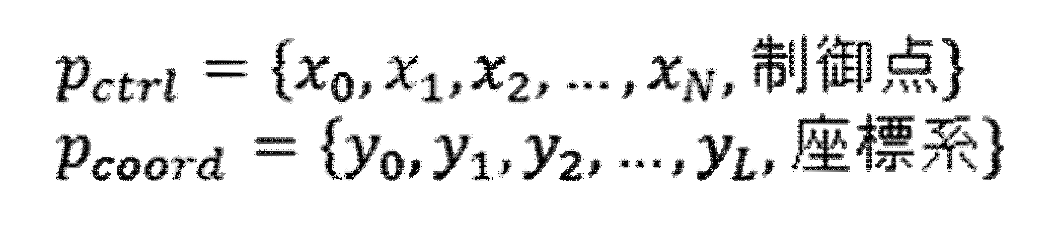

また、指定座標系上における制御点の現在位置・姿勢を表す同次マトリクスMcwは、Mcを用いて以下の式で求められる。





Rot(θ’,axis):ベクトルaxis方向回りにθ’だけ回転する回転行列。[数7]にて説明した行列Rと同様のもの。



〔10.1 実施例1〕
以下、図35~図41を参照することにより、実施例1について説明する。実施例1は、機械構成木において、3次元の回転誤差に係る誤差ノードを機械原点の隣りに挿入する実施例である。









以下、図42及び図43を参照することにより、実施例2について説明する。実施例2は、機械構成木において、3次元の回転誤差に係る誤差ノードをミラー位置に挿入する実施例である。


これら、355A、354、355Bを結合したノードは、誤差ノード挿入位置357Zでの誤差に相当する。
以下、図44及び図45を参照することにより、実施例3について説明する。実施例3は、機械構成木において、各軸の直角度誤差に対応する誤差ノードを、各軸に対応する誤差ノードの1つ機械原点側に挿入する実施例である。
なお、ボールバーとは、変位計を内蔵した伸縮自在な棒の両端に取り付けた二つの球の間の相対変位を測定する測定器である。図44は各軸周りの直角度誤差を示す。



以下、図46~図48を参照することにより、実施例4について説明する。実施例4は、機械構成木に対して、工作機械の機上で測定した誤差に係る誤差ノードを挿入する実施例である。



球76~79の座標の測定値から得られる、球76から球77へのベクトルの測定値を、






本実施形態に係る制御装置は、制御対象の機械構成を、構成要素をノードとするグラフ形式で表現し、保持する制御装置(例えば、上記の「制御装置100」)であって、前記機械構成のグラフの各ノードに対し、制御点及び座標系をノードとして挿入する制御点座標系挿入部(例えば、上記の「制御点座標系挿入部113」)と、前記挿入された前記制御点及び前記座標系に識別子を割り当てる識別子割り当て部(例えば、上記の「識別子割り当て部114」)と、前記制御対象における機械誤差に係る情報と、前記機械誤差を観測した座標系に割り当てられた識別子とを記憶する誤差情報記憶部(例えば、上記の「誤差情報記憶部142」)と、前記機械誤差を等価な誤差ノードに変換する誤差ノード生成部(例えば、上記の「誤差ノード生成部115」)と、前記機械構成のグラフにおいて、前記誤差ノードを追加する誤差ノード追加部(例えば、上記の「誤差ノード追加部112」)と、前記機械構成のグラフに対し、前記識別子により制御点及び座標系を1組以上指定する制御点座標系指定部(例えば、上記の「制御点座標系指定部116」」)と、前記制御点座標系指定部により指定された前記制御点と前記座標系により、プログラム中で指令された1つ以上の指令値が、どの制御点に対するどの座標系上の座標値に対応するか判断する指令値判断部と、前記制御点の前記座標値が前記指令値となるように、前記制御点の移動を指令する移動指令部(例えば、上記の「移動指令部118」)と、を備える。
100 数値制御装置
111 グラフ生成部
112 誤差ノード追加部
113 制御点座標系挿入部
114 識別子割り当て部
115 誤差ノード生成部
116 制御点座標系指定部
117 指令値判断部
118 移動指令部
141 機械構成グラフ記憶部
142 誤差情報記憶部
181 連立方程式生成部
182 連立方程式求解部
183 移動パルス生成部
Claims (4)
- 制御対象の機械構成を、構成要素をノードとするグラフ形式で表現し、保持する制御装置であって、
前記機械構成のグラフの各ノードに対し、制御点及び座標系をノードとして挿入する制御点座標系挿入部と、
前記挿入された前記制御点及び前記座標系に識別子を割り当てる識別子割り当て部と、
前記制御対象における機械誤差に係る情報と、前記機械誤差を観測した座標系に割り当てられた識別子とを記憶する誤差情報記憶部と、
前記機械誤差を等価な誤差ノードに変換する誤差ノード生成部と、
前記機械構成のグラフにおいて、前記誤差ノードを追加する誤差ノード追加部と、
前記機械構成のグラフに対し、前記識別子により制御点及び座標系を1組以上指定する制御点座標系指定部と、
前記制御点座標系指定部により指定された前記制御点と前記座標系により、プログラム中で指令された1つ以上の指令値が、どの制御点に対するどの座標系上の座標値に対応するか判断する指令値判断部と、
前記制御点の前記座標値が前記指令値となるように、前記制御点の移動を指令する移動指令部と、を備える制御装置。 - 制御対象の機械構成を、構成要素をノードとするグラフ形式で表現し、保持する制御装置であって、
前記機械構成のグラフの各ノードに対し、制御点及び座標系を情報として持たせる制御点座標系挿入部と、
前記挿入された前記制御点及び前記座標系に識別子を割り当てる識別子割り当て部と、
前記制御対象における機械誤差に係る情報と、前記機械誤差を観測した座標系に割り当てられた識別子とを記憶する誤差情報記憶部と、
前記機械誤差を等価な誤差ノードに変換する誤差ノード生成部と、
前記機械構成のグラフにおいて、前記誤差ノードを追加する誤差ノード追加部と、
前記機械構成のグラフに対し、前記識別子により制御点及び座標系を1組以上指定する制御点座標系指定部と、
前記制御点座標系指定部により指定された前記制御点と前記座標系により、プログラム中で指令された1つ以上の指令値が、どの制御点に対するどの座標系上の座標値に対応するか判断する指令値判断部と、
前記制御点の前記座標値が前記指令値となるように、前記制御点の移動を指令する移動指令部と、を備える制御装置。 - 前記機械構成のグラフは、複数の軸をまとめて1つにしたユニットを構成要素として含
むことができる、請求項1又は2のいずれか1項に記載の制御装置。 - ユーザが記述したスクリプトを解析することにより、前記ユニットを定義し、定義され
た前記ユニットを前記機械構成のグラフの構成要素として含むことができる、請求項3に
記載の制御装置。
Priority Applications (4)
| Application Number | Priority Date | Filing Date | Title |
|---|---|---|---|
| JP2021526389A JP6940724B1 (ja) | 2020-02-04 | 2021-02-02 | 制御装置 |
| US17/789,418 US12461503B2 (en) | 2020-02-04 | 2021-02-02 | Control device |
| CN202180012329.8A CN115066660B (zh) | 2020-02-04 | 2021-02-02 | 控制装置 |
| DE112021000864.1T DE112021000864B4 (de) | 2020-02-04 | 2021-02-02 | Steuerung und Konfiguration einer Steuerung |
Applications Claiming Priority (2)
| Application Number | Priority Date | Filing Date | Title |
|---|---|---|---|
| JP2020017342 | 2020-02-04 | ||
| JP2020-017342 | 2020-02-04 |
Publications (1)
| Publication Number | Publication Date |
|---|---|
| WO2021157574A1 true WO2021157574A1 (ja) | 2021-08-12 |
Family
ID=77200196
Family Applications (1)
| Application Number | Title | Priority Date | Filing Date |
|---|---|---|---|
| PCT/JP2021/003743 Ceased WO2021157574A1 (ja) | 2020-02-04 | 2021-02-02 | 制御装置 |
Country Status (5)
| Country | Link |
|---|---|
| US (1) | US12461503B2 (ja) |
| JP (1) | JP6940724B1 (ja) |
| CN (1) | CN115066660B (ja) |
| DE (1) | DE112021000864B4 (ja) |
| WO (1) | WO2021157574A1 (ja) |
Citations (4)
| Publication number | Priority date | Publication date | Assignee | Title |
|---|---|---|---|---|
| JP2018120543A (ja) * | 2017-01-27 | 2018-08-02 | ファナック株式会社 | 数値制御装置 |
| JP2019012342A (ja) * | 2017-06-29 | 2019-01-24 | ファナック株式会社 | 仮想オブジェクト表示システム |
| JP6549683B2 (ja) * | 2016-12-12 | 2019-07-24 | ファナック株式会社 | 制御装置 |
| JP2019212041A (ja) * | 2018-06-05 | 2019-12-12 | ファナック株式会社 | 仮想オブジェクト表示システム |
Family Cites Families (14)
| Publication number | Priority date | Publication date | Assignee | Title |
|---|---|---|---|---|
| JPS515024B2 (ja) * | 1972-07-13 | 1976-02-17 | ||
| JPH07141317A (ja) * | 1993-09-22 | 1995-06-02 | Sanyo Electric Co Ltd | 階層型ツリー構造を有するニューロファジィ知識獲得装置 |
| JP5105024B2 (ja) | 2010-02-25 | 2012-12-19 | 三菱電機株式会社 | 数値制御装置 |
| KR101126808B1 (ko) * | 2010-03-02 | 2012-03-23 | 경북대학교 산학협력단 | 다축 제어 기계의 오차 평가 방법 및 장치 |
| JP2012248098A (ja) * | 2011-05-30 | 2012-12-13 | Okuma Corp | 機械の誤差補償値計算方法 |
| JP5792251B2 (ja) * | 2013-09-27 | 2015-10-07 | ファナック株式会社 | 誤差補正量作成装置 |
| JP6676286B2 (ja) * | 2015-05-12 | 2020-04-08 | キヤノン株式会社 | 情報処理方法、および情報処理装置 |
| CN104950808B (zh) * | 2015-07-20 | 2017-05-10 | 攀枝花学院 | 基于加强朴素贝叶斯网络的机床热误差补偿方法 |
| US11402818B2 (en) * | 2016-12-12 | 2022-08-02 | Fanuc Corporation | Numerical controller and data structure |
| JP6538761B2 (ja) * | 2017-06-22 | 2019-07-03 | ファナック株式会社 | 数値制御装置 |
| CN109726066B (zh) * | 2017-10-27 | 2022-06-24 | 伊姆西Ip控股有限责任公司 | 用于标识存储系统中的问题部件的方法和设备 |
| CN108555908B (zh) * | 2018-04-12 | 2020-07-28 | 同济大学 | 一种基于rgbd相机的堆叠工件姿态识别及拾取方法 |
| CN108469783B (zh) * | 2018-05-14 | 2021-02-02 | 西北工业大学 | 基于贝叶斯网络的深孔圆度误差预测方法 |
| CN108873807B (zh) * | 2018-07-12 | 2021-04-09 | 上海优尼斯工业服务有限公司 | 一种考虑加工稳定性的三轴数控机床精度评价方法 |
-
2021
- 2021-02-02 US US17/789,418 patent/US12461503B2/en active Active
- 2021-02-02 WO PCT/JP2021/003743 patent/WO2021157574A1/ja not_active Ceased
- 2021-02-02 JP JP2021526389A patent/JP6940724B1/ja active Active
- 2021-02-02 CN CN202180012329.8A patent/CN115066660B/zh active Active
- 2021-02-02 DE DE112021000864.1T patent/DE112021000864B4/de active Active
Patent Citations (4)
| Publication number | Priority date | Publication date | Assignee | Title |
|---|---|---|---|---|
| JP6549683B2 (ja) * | 2016-12-12 | 2019-07-24 | ファナック株式会社 | 制御装置 |
| JP2018120543A (ja) * | 2017-01-27 | 2018-08-02 | ファナック株式会社 | 数値制御装置 |
| JP2019012342A (ja) * | 2017-06-29 | 2019-01-24 | ファナック株式会社 | 仮想オブジェクト表示システム |
| JP2019212041A (ja) * | 2018-06-05 | 2019-12-12 | ファナック株式会社 | 仮想オブジェクト表示システム |
Also Published As
| Publication number | Publication date |
|---|---|
| US12461503B2 (en) | 2025-11-04 |
| DE112021000864T5 (de) | 2022-11-17 |
| CN115066660B (zh) | 2025-08-22 |
| CN115066660A (zh) | 2022-09-16 |
| JP6940724B1 (ja) | 2021-09-29 |
| DE112021000864B4 (de) | 2025-09-11 |
| US20230050158A1 (en) | 2023-02-16 |
| JPWO2021157574A1 (ja) | 2021-08-12 |
Similar Documents
| Publication | Publication Date | Title |
|---|---|---|
| CN108227631B (zh) | 数值控制装置以及数据结构 | |
| JP6549683B2 (ja) | 制御装置 | |
| TWI381256B (zh) | 用於控制一工具機系統之複數個可移動軸之移動之系統、方法及電腦可讀媒體 | |
| US11958190B2 (en) | Information processing method and information processing apparatus | |
| US8000838B2 (en) | Systems and methods that facilitate motion control through coordinate system transformations | |
| JP5620825B2 (ja) | 複合機械加工の方法および装置 | |
| JP6806736B2 (ja) | 位置情報表示システム | |
| CN108363360B (zh) | 数值控制装置 | |
| CN112987650B (zh) | 控制系统 | |
| JP6781201B2 (ja) | 仮想オブジェクト表示システム | |
| JP4644490B2 (ja) | ツール運動の直接制御のために複雑なn曲線を描写するためのシステムおよび方法 | |
| JP6538761B2 (ja) | 数値制御装置 | |
| JP2021151696A (ja) | 情報処理方法、情報処理装置、ロボット装置、情報処理プログラム、およびコンピュータ読み取り可能な記録媒体 | |
| JP6900533B2 (ja) | 情報処理方法、情報処理装置、ロボット装置、情報処理プログラム、およびコンピュータ読み取り可能な記録媒体 | |
| JP6940724B1 (ja) | 制御装置 | |
| TW202011131A (zh) | 加工傾斜平面的多軸工具機的程式碼產生方法及其裝置 | |
| CN111650887A (zh) | 控制系统 | |
| WO2024185132A1 (ja) | 数値制御装置 | |
| CN121374077A (zh) | 机器人连杆组装方法、电子设备及存储介质 | |
| da Motta et al. | An off-line robot programming system including workcell and robot calibration | |
| JPH0735031B2 (ja) | ロボツトのオフライン・プロミラミング装置 |
Legal Events
| Date | Code | Title | Description |
|---|---|---|---|
| ENP | Entry into the national phase |
Ref document number: 2021526389 Country of ref document: JP Kind code of ref document: A |
|
| 121 | Ep: the epo has been informed by wipo that ep was designated in this application |
Ref document number: 21751222 Country of ref document: EP Kind code of ref document: A1 |
|
| 122 | Ep: pct application non-entry in european phase |
Ref document number: 21751222 Country of ref document: EP Kind code of ref document: A1 |
|
| WWG | Wipo information: grant in national office |
Ref document number: 202180012329.8 Country of ref document: CN |
|
| WWG | Wipo information: grant in national office |
Ref document number: 112021000864 Country of ref document: DE |
|
| WWG | Wipo information: grant in national office |
Ref document number: 17789418 Country of ref document: US |