WO2021157448A1 - データ処理システム、データ転送装置およびコンテキストスイッチ方法 - Google Patents
データ処理システム、データ転送装置およびコンテキストスイッチ方法 Download PDFInfo
- Publication number
- WO2021157448A1 WO2021157448A1 PCT/JP2021/002880 JP2021002880W WO2021157448A1 WO 2021157448 A1 WO2021157448 A1 WO 2021157448A1 JP 2021002880 W JP2021002880 W JP 2021002880W WO 2021157448 A1 WO2021157448 A1 WO 2021157448A1
- Authority
- WO
- WIPO (PCT)
- Prior art keywords
- application
- processing
- processing unit
- context
- unit
- Prior art date
- Legal status (The legal status is an assumption and is not a legal conclusion. Google has not performed a legal analysis and makes no representation as to the accuracy of the status listed.)
- Ceased
Links
Images





Classifications
-
- G—PHYSICS
- G06—COMPUTING OR CALCULATING; COUNTING
- G06F—ELECTRIC DIGITAL DATA PROCESSING
- G06F8/00—Arrangements for software engineering
- G06F8/60—Software deployment
- G06F8/61—Installation
-
- G—PHYSICS
- G06—COMPUTING OR CALCULATING; COUNTING
- G06F—ELECTRIC DIGITAL DATA PROCESSING
- G06F9/00—Arrangements for program control, e.g. control units
- G06F9/06—Arrangements for program control, e.g. control units using stored programs, i.e. using an internal store of processing equipment to receive or retain programs
- G06F9/46—Multiprogramming arrangements
- G06F9/461—Saving or restoring of program or task context
-
- G—PHYSICS
- G06—COMPUTING OR CALCULATING; COUNTING
- G06F—ELECTRIC DIGITAL DATA PROCESSING
- G06F15/00—Digital computers in general; Data processing equipment in general
- G06F15/16—Combinations of two or more digital computers each having at least an arithmetic unit, a program unit and a register, e.g. for a simultaneous processing of several programs
- G06F15/177—Initialisation or configuration control
-
- G—PHYSICS
- G06—COMPUTING OR CALCULATING; COUNTING
- G06F—ELECTRIC DIGITAL DATA PROCESSING
- G06F15/00—Digital computers in general; Data processing equipment in general
- G06F15/76—Architectures of general purpose stored program computers
- G06F15/80—Architectures of general purpose stored program computers comprising an array of processing units with common control, e.g. single instruction multiple data processors
-
- G—PHYSICS
- G06—COMPUTING OR CALCULATING; COUNTING
- G06F—ELECTRIC DIGITAL DATA PROCESSING
- G06F9/00—Arrangements for program control, e.g. control units
- G06F9/06—Arrangements for program control, e.g. control units using stored programs, i.e. using an internal store of processing equipment to receive or retain programs
- G06F9/46—Multiprogramming arrangements
- G06F9/48—Program initiating; Program switching, e.g. by interrupt
-
- H—ELECTRICITY
- H04—ELECTRIC COMMUNICATION TECHNIQUE
- H04W—WIRELESS COMMUNICATION NETWORKS
- H04W4/00—Services specially adapted for wireless communication networks; Facilities therefor
- H04W4/02—Services making use of location information
- H04W4/021—Services related to particular areas, e.g. point of interest [POI] services, venue services or geofences
-
- G—PHYSICS
- G06—COMPUTING OR CALCULATING; COUNTING
- G06F—ELECTRIC DIGITAL DATA PROCESSING
- G06F9/00—Arrangements for program control, e.g. control units
- G06F9/06—Arrangements for program control, e.g. control units using stored programs, i.e. using an internal store of processing equipment to receive or retain programs
- G06F9/30—Arrangements for executing machine instructions, e.g. instruction decode
- G06F9/30003—Arrangements for executing specific machine instructions
- G06F9/30076—Arrangements for executing specific machine instructions to perform miscellaneous control operations, e.g. NOP
- G06F9/3009—Thread control instructions
-
- G—PHYSICS
- G06—COMPUTING OR CALCULATING; COUNTING
- G06F—ELECTRIC DIGITAL DATA PROCESSING
- G06F9/00—Arrangements for program control, e.g. control units
- G06F9/06—Arrangements for program control, e.g. control units using stored programs, i.e. using an internal store of processing equipment to receive or retain programs
- G06F9/30—Arrangements for executing machine instructions, e.g. instruction decode
- G06F9/30098—Register arrangements
- G06F9/30101—Special purpose registers
-
- G—PHYSICS
- G06—COMPUTING OR CALCULATING; COUNTING
- G06F—ELECTRIC DIGITAL DATA PROCESSING
- G06F9/00—Arrangements for program control, e.g. control units
- G06F9/06—Arrangements for program control, e.g. control units using stored programs, i.e. using an internal store of processing equipment to receive or retain programs
- G06F9/30—Arrangements for executing machine instructions, e.g. instruction decode
- G06F9/30098—Register arrangements
- G06F9/30105—Register structure
- G06F9/30116—Shadow registers, e.g. coupled registers, not forming part of the register space
-
- G—PHYSICS
- G06—COMPUTING OR CALCULATING; COUNTING
- G06F—ELECTRIC DIGITAL DATA PROCESSING
- G06F9/00—Arrangements for program control, e.g. control units
- G06F9/06—Arrangements for program control, e.g. control units using stored programs, i.e. using an internal store of processing equipment to receive or retain programs
- G06F9/30—Arrangements for executing machine instructions, e.g. instruction decode
- G06F9/30098—Register arrangements
- G06F9/3012—Organisation of register space, e.g. banked or distributed register file
-
- G—PHYSICS
- G06—COMPUTING OR CALCULATING; COUNTING
- G06F—ELECTRIC DIGITAL DATA PROCESSING
- G06F9/00—Arrangements for program control, e.g. control units
- G06F9/06—Arrangements for program control, e.g. control units using stored programs, i.e. using an internal store of processing equipment to receive or retain programs
- G06F9/30—Arrangements for executing machine instructions, e.g. instruction decode
- G06F9/30098—Register arrangements
- G06F9/3012—Organisation of register space, e.g. banked or distributed register file
- G06F9/30123—Organisation of register space, e.g. banked or distributed register file according to context, e.g. thread buffers
-
- G—PHYSICS
- G06—COMPUTING OR CALCULATING; COUNTING
- G06F—ELECTRIC DIGITAL DATA PROCESSING
- G06F9/00—Arrangements for program control, e.g. control units
- G06F9/06—Arrangements for program control, e.g. control units using stored programs, i.e. using an internal store of processing equipment to receive or retain programs
- G06F9/30—Arrangements for executing machine instructions, e.g. instruction decode
- G06F9/30098—Register arrangements
- G06F9/30141—Implementation provisions of register files, e.g. ports
-
- G—PHYSICS
- G06—COMPUTING OR CALCULATING; COUNTING
- G06F—ELECTRIC DIGITAL DATA PROCESSING
- G06F9/00—Arrangements for program control, e.g. control units
- G06F9/06—Arrangements for program control, e.g. control units using stored programs, i.e. using an internal store of processing equipment to receive or retain programs
- G06F9/30—Arrangements for executing machine instructions, e.g. instruction decode
- G06F9/30145—Instruction analysis, e.g. decoding, instruction word fields
-
- G—PHYSICS
- G06—COMPUTING OR CALCULATING; COUNTING
- G06F—ELECTRIC DIGITAL DATA PROCESSING
- G06F9/00—Arrangements for program control, e.g. control units
- G06F9/06—Arrangements for program control, e.g. control units using stored programs, i.e. using an internal store of processing equipment to receive or retain programs
- G06F9/30—Arrangements for executing machine instructions, e.g. instruction decode
- G06F9/38—Concurrent instruction execution, e.g. pipeline or look ahead
- G06F9/3867—Concurrent instruction execution, e.g. pipeline or look ahead using instruction pipelines
-
- G—PHYSICS
- G06—COMPUTING OR CALCULATING; COUNTING
- G06F—ELECTRIC DIGITAL DATA PROCESSING
- G06F9/00—Arrangements for program control, e.g. control units
- G06F9/06—Arrangements for program control, e.g. control units using stored programs, i.e. using an internal store of processing equipment to receive or retain programs
- G06F9/30—Arrangements for executing machine instructions, e.g. instruction decode
- G06F9/38—Concurrent instruction execution, e.g. pipeline or look ahead
- G06F9/3885—Concurrent instruction execution, e.g. pipeline or look ahead using a plurality of independent parallel functional units
Definitions
- This disclosure relates to data processing technology, especially data processing systems, data transfer devices and context switching methods.
- the processing unit that executes processing related to multiple applications in a time-division manner, it is necessary to perform a context switch when switching the application to be executed.
- the processing unit for example, GPU, etc.
- the processing unit may have thousands or more registers, and the context of the application executed in the processing unit may have a size of several tens of MB or more.
- the context switch of the processing unit may take a long time.
- the present disclosure has been made in view of such a situation, and one purpose is to suppress the processing delay associated with the context switch.
- a data processing system includes a processing unit that executes processing related to a plurality of applications in a time-divided manner, and a data transfer unit that transfers data between the processing unit and the memory. Be prepared.
- the data transfer unit is executed in the processing unit without going through the processing of the detection unit that detects the switching timing of the application to be executed in the processing unit and the software that manages a plurality of applications when the switching timing is detected.
- It includes a transfer execution unit that executes a transfer process that saves the context of the application from the processing unit to the memory and sets the context of the application to be executed next in the processing unit from the memory to the processing unit.
- Another aspect of the present invention is a data transfer device.
- This device performs processing of the detection unit that detects the switching timing of the application to be executed in the processing unit that executes processing related to multiple applications in a timely manner, and processing of software that manages multiple applications when the switching timing is detected.
- the transfer execution unit that executes the transfer process that saves the context of the application executed in the processing unit from the processing unit to the memory and sets the context of the application to be executed next in the processing unit from the memory to the processing unit without going through. And.
- Yet another aspect of the present invention is the context switching method.
- This method involves a step of detecting the switching timing of the application to be executed in the processing unit that executes processing related to a plurality of applications in a time-divided manner, and processing of software that manages the multiple applications when the switching timing is detected. Instead, the step of executing the transfer process of saving the context of the application executed in the processing unit from the processing unit to the memory and setting the context of the application to be executed next in the processing unit from the memory to the processing unit.
- the computer runs.
- FIG. 9A is a diagram showing an example of internal processing at the time of context switching in the first embodiment
- FIG. 9B is a diagram showing an example of internal processing at the time of context switching in the modified example.
- the embodiment is a processing unit that executes processing related to a plurality of applications in a time division manner.
- a technique for executing a context switch in a processing unit shared in a time division by a plurality of applications at high speed is proposed.
- the technique of the embodiment is also effective for an operation such as suspend or hibernation in which a system pauses while holding a state and then resumes execution from the held state, and speeds up the operation. Can be done.
- the processing unit may be a hardware functional block in SOC (System-On-a-Chip) or the like. Further, the processing unit may be a processor such as (1) CPU (Central Processing Unit), DSP (Digital Signal Processor), GPU (Graphics Processing Unit), NPU (Network Processing Unit), or (2) video. It may be a video codec block that performs compression and decompression. Of the video codec blocks, the block that performs video compression is also referred to as the "video encoder" below. In addition, the processing unit executes (3) video resolution conversion, image quality conversion, multiplexing, etc., and processes pixel data at specified timings. Video (display) pipeline block (hereinafter also referred to as "video pipeline”). It may be called), or it may be (4) an input / output interface block to a peripheral device.
- Video (display) pipeline block hereinafter also referred to as "video pipeline”
- processing unit may execute a plurality of application task threads (hereinafter referred to as "application”) in a time-division manner. Since the processing unit executes processing unique to each application, it holds data that specifies the application to be executed, data that specifies settings / operations, and the like. When starting the process, the processing unit sets up the data and then starts the process. The processing unit generates application-specific data, settings, operating states, etc. at any time while executing processing related to the application.
- the data required and generated in the processing related to these individual applications are hereinafter referred to as "contexts". That is, the context is data necessary for ensuring reproducibility to obtain the same result when the same process is executed again in the same processing unit.
- switching processing in the processing unit is required.
- the application switching by time division is performed by saving the context of the application executed by the processing unit to the outside and setting the context of the application to be executed next in the processing unit.
- This switching is hereinafter referred to as a "context switch". While saving and setting the context, it is necessary to stop the processing of the processing unit. In order to improve the utilization efficiency of the processing unit and reduce the processing delay in the processing unit (in other words, enhance the real-time performance), it is required to speed up the context switch and shorten the processing stop time of the processing unit.
- Some CPUs have hardware functions that support the speeding up of context switches. However, its function is only that the hardware automatically saves and sets the context for some registers accessible by the software, and covers the saving and setting of all the contexts held internally. is not it. Therefore, other contexts are saved and set by sequential processing by software. This can be said when a plurality of applications are executed with an OS (Windows (registered trademark) or Linux (registered trademark)) on a general x86 or ARM architecture CPU.
- OS Windows (registered trademark) or Linux (registered trademark)
- the data processing system of the embodiment includes a dedicated functional block that executes context transfer for the context switch of the processing unit.
- the context switch can be executed at high speed even in the combination of the processing unit and the application that use a huge amount of context. In other words, it suppresses the processing delay associated with context switching.
- this dedicated functional block is referred to as a "context switch DMA (Direct Memory Access) engine” and is referred to as a "CDS DMA engine”.
- the CDMA engine When the CDMA engine is notified of the application switching timing or detects it by itself, (1) selects the context of each application stored in the memory, transfers it to the processing unit without using software, and sets it. Alternatively, (2) the context held in the processing unit is transferred / saved to the memory without going through software.
- the transfer target in the context switch includes the contents of the register, the contents of the memory in the processing unit, the state state of the state machine (internal state of the state transition), and the current state of the outstanding processing being executed on the fly.
- These transfer targets are not limited to those that can be accessed from software, and also include those that are built in by the processing unit and hold the context. That is, the transfer target by the context switch in the embodiment also includes a context that is normally inaccessible from software.
- the CDMA engine When the CDMA engine is notified of the application switching timing or detects it by itself, it issues an operation stop instruction to the processing unit, and also processes that are being executed on the fly, especially out standing and out of order. ) May start saving the context and setting as soon as it confirms the completion of the process that requires the commit process.
- the CDMA engine may instruct the start of processing of the next application after the context is saved and the setting is completed.
- the processing unit may be provided with a plurality of queues for a plurality of applications. Data indicating an instruction to the processing unit may be written to each queue at any time from the corresponding application.
- the processing unit may switch the queue for reading data when a context switch occurs. Further, the timing at which data is written to the queue corresponding to a certain application does not have to be limited to the period during which the application occupies the processing unit. In this case, each application can continue to queue the processing instructions even during the execution of the context switch, and the processing stop time associated with the context switching can be shortened. Further, it is possible to cope with the case where the software on the CPU that writes data to the queue operates asynchronously with the processing unit (for example, GPU).
- the processing unit for example, GPU
- the CSDMA engine may execute a context switch triggered by the start of a vertical blanking interval or a horizontal blanking interval.
- the GPU, the video pipeline, the video encoder, or the like can be temporarily stopped during the vertical blanking interval and the horizontal blanking interval. Therefore, the overhead of the context switch can be hidden by executing the context switch during the short vertical blanking interval or the horizontal blanking interval.
- the context switch may be executed in the following steps. (1) The context is set in advance for other multiplexed circuits without pausing the processing unit. (2) The processing of the processing unit is stopped (the commit of the immediately preceding processing may be waited for), the circuit for which the context is set in (1) above is selected, and the execution of the next application is started. (3) Save the context of the application that was being executed in (1) above. As a result, the processing of the context switch and the processing of the processing unit can be time-overlapped, and the processing stop time can be further reduced.
- the circuit that holds the context may be multiplexed, and the processing unit may start the processing of the next application without pausing to wait for the commit processing.
- a plurality of applications may be executed simultaneously while some functional circuits are parallelized to avoid processing failure. As a result, processing of a plurality of applications (which may be outstanding or out-of-order processing) can be executed in parallel, and the downtime due to the context switch can be shortened.
- circuit utilization efficiency, performance scalability and flexibility can be improved.
- FIG. 1 shows the configuration of the computer 10 of the first embodiment.
- the computer 10 may be a server that processes a plurality of applications (games and the like) in parallel in response to requests from the plurality of client devices and provides the processing results (for example, image data) of each application to each client device.
- the computer 10 may be a PC or a game machine (video game console or the like) that executes a plurality of applications in parallel in a time-divided manner and displays a processing result (for example, image data) of each application on a display device.
- the computer 10 includes an SOC (System On a Chip) 11 and a main memory 22.
- SOC11 is an integrated circuit product in which the functions of a data processing system are mounted on one chip.
- the SOC 11 includes a CPU 12, a GPU 14, a video encoder 16, a video pipeline 18, and a video timing generator 20.
- the CPU 12 executes a plurality of applications targeted for parallel processing in a time-division manner. Further, the CPU 12 executes software (hereinafter, also referred to as “management software”) for managing a plurality of applications to be processed in parallel.
- the management software may be software positioned in a layer below the application, such as an OS or middleware, and in the embodiment, the execution order and context switch of a plurality of applications are managed. Some functions of the management software may be executed by the GPU 14, the video encoder 16 or the like (processing unit 46 described later).
- the GPU 14 executes image processing and general-purpose calculation processing related to the plurality of applications in a time-division manner in response to instructions of the plurality of applications executed in the CPU 12 in a time-division manner. For example, the GPU 14 generates image data for each of the plurality of applications, and writes the generated image data in the frame buffer corresponding to each application.
- the video encoder 16 executes image compression processing of a plurality of applications to be processed in parallel in a time-division manner. For example, the video encoder 16 sequentially reads the image data of each application from a plurality of frame buffers corresponding to the plurality of applications, and executes compression coding processing on the read image data.
- the video pipeline 18 is an image supplied from another block of the image supply source (for example, GPU 14 or a video decoder (not shown)), in other words, resolution conversion and image quality conversion for images of a plurality of applications to be processed in parallel. Or perform multiplexing in a time division manner.
- another block of the image supply source for example, GPU 14 or a video decoder (not shown)
- the case of image transfer between the GPU 14, the video encoder 16, and the video pipeline 18 includes the following three patterns.
- the processing result of the GPU 14 is also input to the video pipeline 18. That is, there are both a pattern in which the video encoder 16 directly refers to the image generated by the CPU 12 and a pattern in which the video pipeline 18 refers to the processed image.
- the GPU 14, the video encoder 16, and the video pipeline 18 execute the processing related to a plurality of applications to be parallel processed in a time-division manner.
- the GPU 14, the video encoder 16, and the video pipeline 18 are referred to. Collectively, they are called "processing unit 46".
- the video timing generator 20 notifies each device of various timings (which can be said to be video timings) related to image display.
- the video timing generator 20 transmits a signal notifying the start of the vertical blanking interval (or the period corresponding to the vertical blanking interval) of the display device to the CPU 12, the GPU 14, the video encoder 16, and the video pipeline 18. ..
- the SOC 11 further includes a CDMA engine 40, a CDMA engine 42, and a CDMA engine 44 (collectively referred to as "CDMA engine 48").
- the CDRM engine 48 is a data transfer unit that executes context transfer for a context switch by DMA.
- the CDMA engine 40 transfers the context between the GPU 14 and the main memory 22 in accordance with the context switch in the GPU 14.
- the CDMA engine 42 transfers the context between the video encoder 16 and the main memory 22 in accordance with the context switch in the video encoder 16.
- the CDMA engine 44 transfers the context between the video pipeline 18 and the main memory 22 in accordance with the context switch in the video pipeline 18.
- the path 50 is a path for normal memory access (including command reading and image data storage) by the GPU 14.
- the path 52 is an access path (for setting / confirmation / notification / control) from the software (for example, management software) executed by the CPU 12 to the GPU 14 and the CDRM engine 40.
- the path 52 is also connected to another block for the same purpose. In the figure, a part having a black circle at the intersection of the lines indicates a state in which the line is connected, and a part having no black circle at the intersection of the lines indicates a state in which the line is not connected.
- the path 54 is a context setting path from the main memory 22 to the GPU 14.
- the path 56 is a context evacuation path from the GPU 14 to the main memory 22.
- the path 58 is a path in which the CDMA engine 40 monitors the processing status of the GPU 14.
- the path 60 is a path in which the CDMA engine 40 instructs the GPU 14 to stop and start (restart) application processing.
- the path 62 is a path for notifying the GPU 14 and the CDMA engine 40 of the start of the vertical blanking interval from the video timing generator 20.
- the path 62 is also connected to another block for the same purpose. The same applies to each path between the video encoder 16 and the CSDMA engine 42, and each path between the video pipeline 18 and the CSDMA engine 44.
- the main memory 22 stores data referenced or updated by the SOC 11.
- the main memory 22 stores the GPU command buffer 30, the GPU context 32, the video encoder context 34, and the video pipeline context 36.
- the GPU context 32 is a context used by the GPU 14 regarding a plurality of applications (for example, App A, App B, etc.) executed in parallel in SOC 11.
- the video encoder context 34 is the context used by the video encoder 16 for a plurality of applications running in parallel at SOC 11.
- the video pipeline context 36 is the context used in the video pipeline 18 for a plurality of applications running in parallel in SOC 11.
- the GPU command buffer 30 includes a plurality of queues (for example, for App A, for App B, etc.) corresponding to a plurality of applications processed in parallel by SOC 11.
- each queue of the GPU command buffer 30 commands instructing processing contents related to each application are written by the CPU 12 and stored.
- each application executed by the CPU 12 stores commands such as drawing instructions in the queue of the GPU command buffer 30 corresponding to its own application.
- the GPU 14 reads a command from the queue of the GPU command buffer 30 corresponding to the application to be executed.
- the GPU 14 switches the queue for reading commands when switching the application to be executed.
- the CPU 12 can operate asynchronously with the processing unit 46 (for example, the GPU 14, the video encoder 16, and the video pipeline 18). That is, each application executed in parallel (time division or the like) in the CPU 12 can store a command related to its own application in the GPU command buffer 30 at any time while the processing unit 46 is processing another application. .. In other words, it is possible to deal with the case where the software on the CPU 12 that writes to the GPU command buffer 30 operates asynchronously with the processing unit 46. As a result, even during the execution of the context switch in the processing unit 46, each application on the CPU 12 can accumulate the processing instructions in the GPU command buffer 30, so that the processing delay can be suppressed.
- the processing unit 46 for example, the GPU 14, the video encoder 16, and the video pipeline 18
- the management software executed by the CPU 12 performs the initial setting of the context switch. For example, the management software allocates the areas of the GPU context 32, the video encoder context 34, and the video pipeline context 36 in the main memory 22 for each of the plurality of applications to be processed in parallel. In addition, the management software notifies the CDMA engine 48 (CDMA engine 40, CDMA engine 42, CDMA engine 44) of the context storage position (address, etc.) of each application.
- CDMA engine 48 CDMA engine 40, CDMA engine 42, CDMA engine 44
- the management software notifies the processing unit 46 and the CDMA engine 48 of the execution order of a plurality of applications to be processed in parallel.
- the processing unit 46 and the CDMA engine 48 grasp the application to be executed this time and the application to be executed next time based on the notification and the setting from the management software.
- the CPU 12 may also be provided with a CDMA engine 48 for a context switch. In this case, the CPU 12 may operate in synchronization with the processing unit 46.
- FIG. 2 is a block diagram showing a detailed configuration of the processing unit 46 (specifically, GPU 14, video encoder 16, video pipeline 18) and CDMA engine 48 of FIG.
- the set of the processing unit 46 and the CDMA engine 48 of FIG. 2 corresponds to the set of the GPU 14 and the CDMA engine 40 of FIG. 1, the set of the video encoder 16 and the CDMA engine 42, and the set of the video pipeline 18 and the CDMA engine 44, respectively. .. That is, the configuration of the processing unit 46 of FIG. 2 is applicable to at least one of the GPU 14, the video encoder 16, and the video pipeline 18. Further, the configuration of the CDMA engine 48 in FIG. 2 is applicable to at least one of the CDMA engine 40, the CDMA engine 42, and the CDMA engine 44.
- Each block shown in the block diagram of the present disclosure can be realized by an element such as a computer CPU / memory or a mechanical device in terms of hardware, and can be realized by a computer program or the like in terms of software. , Draws a functional block realized by their cooperation. Those skilled in the art will understand that these functional blocks can be realized in various ways by combining hardware and software.
- the processing unit 46 includes a first functional circuit 70 and a second functional circuit 71.
- the first functional circuit 70 and the second functional circuit 71 execute data processing (for example, image generation processing and compression / decompression processing) related to the application to be executed.
- the processing unit 46 identifies the application to be executed based on the notification and settings from the management software on the CPU 12, and assigns the first functional circuit 70 and the second functional circuit 71 to the application to be executed.
- the processing unit 46 reads various data related to the application to be executed from the main memory 22 and inputs them to the first functional circuit 70 and the second functional circuit 71.
- the GPU 14 as the processing unit 46 reads a command related to the application from the queue of the GPU command buffer 30 corresponding to the application to be executed.
- the GPU 14 also reads other data necessary for drawing an image from the main memory 22.
- the first functional circuit 70 is a circuit that holds the context, which is the data updated during the execution of the application and is the data necessary for reproducing the processing. Further, the first functional circuit 70 is a circuit that needs to be replaced in context according to the application to be executed.
- the first functional circuit 70 includes a state machine 72, a register 73, and a work memory 74.
- the state machine 72 includes a state register and holds the current state of each process being executed by the processing unit 46, in other words, holds the state transition status.
- the register 73 holds the data being set and processed and the result of processing.
- the work memory 74 is an area in the memory of the processing unit 46 that holds internal data, descriptors, and microcode that are updated in response to processing.
- the second functional circuit 71 is data that is updated during the execution of the application and does not hold the context, which is the data necessary for reproducing the processing. Further, the second functional circuit 71 is a circuit that does not require initialization or is a circuit that can be reset all at once, and is, for example, a circuit that performs arithmetic processing and the like.
- the second functional circuit 71 includes a random logic 75, an arithmetic unit 76, and a work memory 77.
- Random logic 75 includes a hard-wired function and includes a flip-flop circuit (latch) that does not require initialization or can be initialized to a certain degree.
- the arithmetic unit 76 includes a data path and a flip-flop circuit (latch) that does not require initialization or can be initialized constantly.
- the work memory 77 is an area other than the work memory 74 in the memory of the processing unit 46.
- the CDMA engine 48 includes a detection unit 80, a monitoring unit 82, an instruction unit 84, and a transfer execution unit 86.
- the detection unit 80 detects the switching timing of the application to be executed by the processing unit 46 (hereinafter, also referred to as “App switching timing”).
- the detection unit 80 of the embodiment detects the start timing of the vertical blanking interval as the application switching timing, and specifically, when the video timing generator 20 notifies the start timing of the vertical blanking interval, the application switching timing is used. Judge that there is.
- the detection unit 80 may detect the start timing of the horizontal blanking interval as the App switching timing. Specifically, the detection unit 80 may determine that it is the App switching timing when the video timing generator 20 notifies the start timing of the horizontal blanking interval.
- the management software on the CPU 12 may notify the processing unit 46 and the CDMA engine 48 of the application switching timing. The detection unit 80 may detect the App switching timing based on the notification from the management software on the CPU 12.
- the monitoring unit 82 monitors the execution state of the processing related to the application in the processing unit 46.
- the processing related to the application in the processing unit 46 includes a plurality of internal processes having a small particle size, and the plurality of internal processes are executed in parallel.
- the monitoring unit 82 confirms the execution state of each internal process (for example, whether or not each internal process is completed).
- the instruction unit 84 instructs the processing unit 46 to stop and start (restart) the processing related to the application.
- the instruction unit 84 may instruct the processing unit 46 to stop the processing related to the application when the App switching timing is detected.
- the processing unit 46 may detect the application switching timing based on the instruction from the instruction unit 84 of the CDMA engine 48, and may determine the application switching timing based on the notification from the management software on the CPU 12 or the video timing generator 20. It may be detected.
- the monitoring unit 82 and the indicating unit 84 have an optional configuration, and the CDMA engine 48 may have a configuration that does not include one or both of the monitoring unit 82 and the indicating unit 84.
- the transfer execution unit 86 executes the context transfer process when the App switching timing is detected. Specifically, the transfer execution unit 86 is a context transfer process of the application executed by the processing unit 46 without going through the processing of software that manages a plurality of applications (management software on the CPU 12 in the embodiment). The context is saved from the processing unit 46 (first functional circuit 70) to the main memory 22 (context storage area of the application).
- the transfer execution unit 86 sets the context of the application to be executed next by the processing unit 46 without going through the processing of software that manages a plurality of applications (management software on the CPU 12 in the embodiment). Read from the main memory 22 (context storage area of the application). The transfer execution unit 86 sets the read context in the processing unit 46 (first functional circuit 70). When the instruction unit 84 detects the completion of the context setting processing by the transfer execution unit 86, the instruction unit 84 may instruct the processing unit 46 to start (restart) the processing related to the application.
- the context to be transferred by the transfer execution unit 86 is data necessary for reproducing the processing of the application (individual internal processing described above) at the time of interruption due to the context switch in the processing unit 46.
- the contexts to be transferred by the transfer execution unit 86 are all the contexts held in the first functional circuit 70 of the processing unit 46, and are software (for example, software on the CPU 12 and on the processing unit 46). Includes contexts that cannot be accessed from the software).
- the context that cannot be accessed from the software may be, for example, a context held in the state machine 72 of the processing unit 46, or a context indicating the state transition status of each internal processing included in the processing of the application. good.
- FIG. 3 shows the video drawing process in the processing unit 46 (for example, GPU 14) in chronological order.
- the figure shows an example in which video drawing processing for four applications (App A, App B, etc.) is executed in a time-division manner.
- each application needs to generate an image at 60 fps (frames per second).
- the processing unit 46 realizes a frame rate of 60 fps per application by generating images of four applications in 1/240 seconds each.
- the processing time of each application is constantly changing based on the drawing content, and it is not always possible to complete the processing within 1/240 seconds.
- the start timing of the vertical blanking interval (timing 90 in FIG. 3) is detected as the application switching timing (in other words, the flip timing for switching the frame buffer of the image writing destination).
- the processing unit 46 can be opened to the next application so that each application can use the processing unit 46 evenly. If the image cannot be generated by the timing 90, the frame is dropped and the previous image of the corresponding application is repeatedly passed to the subsequent processing.
- the period 92 in FIG. 3 corresponds to the vertical blanking interval, and by using the CDRM engine 48, the evacuation / setting of all contexts necessary for reproducing the processing is executed at high speed within this period. In this way, the total of the image generation period indicated by the arrow and the period 92 including the context switch (vertical blanking interval) is controlled to be within 1/240 seconds.
- the application may notify the management software on the CPU 12 that the flip for switching the frame buffer can be executed. Then, the management software on the CPU 12 may notify the processing unit 46 of the App switching timing by itself instead of the start timing of the vertical blanking interval. As a result, the subsequent processing of the corresponding application and the subsequent application can be started ahead of schedule, the delay can be reduced, and the utilization efficiency of the processing unit can be improved.
- the start timing of the horizontal blanking interval may be detected as the App switching timing, or the context switch may be performed within the horizontal blanking interval.
- FIG. 4 shows an example of video timing.
- the figure shows a vertical blanking interval 94 (Vblank) and a horizontal blanking interval 96 (Hblank).
- Vblank vertical blanking interval
- Hblank horizontal blanking interval
- the server draws a video and delivers the video to the client
- an external display that uses video timing may not be connected to the server.
- the video timing may be generated in order to maintain compatibility with the conventional application, and in the embodiment, the App switching timing is detected by using the video timing.
- the GPU 14, the video encoder 16, and the video pipeline 18 can suspend the processing.
- the context switch overhead can be concealed by executing the context switch during a short vertical blanking interval or horizontal blanking interval.
- FIG. 5 shows the configuration of SOC11.
- Each circuit in the SOC 11 usually accesses the main memory 22 via the bus fabric 100 and the memory interface 102.
- the SOC 11 (that is, a semiconductor chip) has a built-in DFT (Design For Test) function (DFT control circuit 104, etc.) for testing whether or not the function operates correctly.
- DFT control circuit 104 Design For Test
- BIST Busilt-In Self Test
- the scan chain 106 is comprehensively connected to the inside of each circuit in the SOC 11 and is used to test each circuit based on the instructions outside the BIST and the chip. By using the scan chain 106, each state value inside the SOC 11 can be set and read.
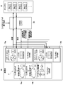
- FIG. 6 also shows the configuration of SOC11.
- the CDMA engine 48 can save and set the context by using the normal data transfer bus (bus fabric 100) and the path 114.
- Path 114 is a path for accessing a circuit that holds a context that cannot be accessed by software.
- this configuration has a demerit that normal data transfer is hindered because the bus fabric 100 is shared with other circuits (CPU 12, etc.) during the context transfer.
- FIG. 7 also shows the configuration of SOC11.
- the CDMA engine 48 can also save and set the context by using the dedicated bus (dedicated route 108) for context transfer and the path 114.
- the dedicated bus dedicated route 108
- FIG. 8 also shows the configuration of SOC11.
- the CDMA engine 48 of the embodiment uses the circuit for DFT (including the scan chain 106) and the circuit for BIST (BIST circuit 110) to save and set the context.
- the CDMA engine 48 reads the context related to the application executed this time from the first functional circuit 70 via the scan chain 106, and stores the read context in the main memory 22 via the BIST circuit 110.
- the CDMA engine 48 reads the context related to the application to be executed next time from the main memory 22 via the BIST circuit 110, and sets the read context in the first functional circuit 70 via the scan chain 106.
- the scan chain 106 By using the scan chain 106 in this way, it is possible to access the context of an internal circuit that the software does not have an access path to, and it is possible to save and set the context necessary for reproducing the process. Further, it is not necessary to newly provide any of the bus fabric 100, the dedicated route 108, and the path 114, and the context transfer can be realized at low cost. Furthermore, it is possible to avoid hindering normal data transfer in SOC 11 due to context transfer.
- the transfer execution unit 86 of the CDMA engine 48 saves the application context held in the first functional circuit 70 (state machine 72 or the like) of the processing unit 46 in the main memory 22.
- the context of the application saved from the processing unit 46 to the main memory 22 and the application context set from the main memory 22 to the processing unit 46 are data held in the state machine 72 or the like, and are at the time when the context switch is started. Contains data indicating the current state of unfinished processing (internal processing with a small grain size) in the processing unit 46.
- the first function circuit 70 and the second function circuit 71 of the processing unit 46 do not perform the internal processing regardless of the state of the internal processing of the application that has been executed until then. Even if it is completed, the internal processing is stopped immediately.
- the transfer execution unit 86 of the CDMA engine 48 is in context regardless of the state of the internal processing of the application that has been executed until then, in other words, even if the internal processing is incomplete. Transfer processing is started.
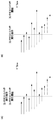
- FIG. 9A shows an example of internal processing at the time of context switching in the first embodiment.
- the horizontal direction is the time-lapse axis, and one arrow indicates the small-grained internal processing included in the processing related to one application.
- the left end of each arrow indicates the start timing of internal processing, and the right end indicates the end timing of internal processing.
- the processing unit 46 of the embodiment immediately stops all internal processing and starts the context switch when the context switch execution instruction is received (that is, when the application switching timing is detected). ..
- the incomplete (that is, on-the-fly outstanding) internal processing (broken line in the figure) at that time is also immediately interrupted, and the context at that time is saved in the main memory 22. Note that the internal processing indicated by the alternate long and short dash line in the figure is not started because it is scheduled to start after receiving the context switch execution instruction.
- the transfer execution unit 86 of the CDRM engine 48 immediately starts the context transfer process (save and setting) when the context switch execution instruction is received (that is, when the application switching timing is detected).
- the state of each internal processing in the processing unit 46 that is, the context including the data that cannot be confirmed by the software (for example, the data held in the state machine 72) is saved.
- the internal processing that was in progress at the time of receiving the context switch execution instruction can be restored to its state and restarted at the next execution. Therefore, in the SOC 11 of the embodiment, the context switch can be started immediately at the time when the context switch execution instruction is received (the time when the application switching timing is detected), and the processing delay can be suppressed.
- the transfer execution unit 86 of the CDMA engine 48 waits until the monitoring unit 82 confirms that the internal processing of the application in the processing unit 46 is completed, and waits until the processing unit 46 confirms that the internal processing of the application has been completed.
- the context transfer process may be started after it is confirmed that the internal process of the application in is completed.
- FIG. 9B shows an example of internal processing at the time of context switching in the modified example. Also in the figure, the internal processing that has been started but not completed (that is, on-the-fly outstanding) when the context switch execution instruction is instructed is shown by the broken line. In this modification, the context switch is started after waiting until the internal processing that has been started but has not been completed at the time of the context switch execution instruction is completed.
- Processing failure inconsistency
- processing cooperation with the outside of the context switch target block is required or when real-time performance is required by completing the processing that has been started but not completed at the time of context switch execution instruction without interruption. Can be prevented.
- the amount of data in the context to be transferred can be reduced.
- FIG. 10 shows the configuration of the processing unit 46 of the second embodiment.
- the pair of the processing unit 46 and the CDMA engine 48 of FIG. 10 corresponds to the set of the GPU 14 and the CDMA engine 40 of FIG. 1, the set of the video encoder 16 and the CDMA engine 42, and the set of the video pipeline 18 and the CDMA engine 44, respectively. .. That is, the configuration of the processing unit 46 of FIG. 10 is applicable to at least one of the GPU 14, the video encoder 16, and the video pipeline 18. Further, the configuration of the CDMA engine 48 in FIG. 10 is applicable to at least one of the CDMA engine 40, the CDMA engine 42, and the CDMA engine 44.
- the processing unit 46 of the second embodiment includes a plurality of first functional circuits 70 that hold the context of the application.
- the processing unit 46 of FIG. 10 includes two first functional circuits 70 (first functional circuit 70a and first functional circuit 70b), but may include three or more first functional circuits 70.
- the transfer execution unit 86 of the CDMA engine 48 of the second embodiment has another first while the processing unit 46 executes the processing of the application using the context of the application held in the first functional circuit 70.
- the context transfer process is executed for the context of another application held in the functional circuit 70.
- the transfer execution unit 86 is held in (1) the first functional circuit 70b.
- the context of Application D (that is, the previously executed Application) is saved in the main memory 22.
- the transfer execution unit 86 reads (2) the context of the application B (that is, the application to be executed next) held in the main memory 22 and sets it in the first functional circuit 70b.
- the processing unit 46 When the processing unit 46 detects the App switching timing while executing the processing of the application using the context of the application held in the first functional circuit 70a, the processing unit 46 immediately stops the processing of the application. Then, the processing unit 46 starts processing of the other application using the context of another application held in the first functional circuit 70b. As a result, the waiting time associated with the context switch (that is, the time waiting for the context to be saved and set) can be made almost zero.
- the configuration of the processing unit 46 of the third embodiment is the same as the configuration of the processing unit 46 of the second embodiment shown in FIG.
- the processing unit 46 executes processing related to the first application using the context of the first application (for example, App A) held in the first functional circuit 70a. Further, the processing unit 46 executes the processing related to the second application by using the context of the second application (for example, App B) held in the first functional circuit 70b.
- the processing unit 46 detects the application switching timing, it identifies the application to be executed next based on the preset settings by the management software on the CPU 12.
- the execution target in the processing unit 46 is switched from the first application (for example, App A) to the second application (for example, App B).
- the processing unit 46 performs the second application among the processing related to the first application.
- the processing related to and the processing that can be mixed and the processing related to the second application are executed in parallel.
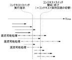
- FIG. 11 shows an example of internal processing at the time of context switching in the third embodiment.
- the figure shows the internal processing of the first application (application before switching).
- the broken line and the alternate long and short dash line in the figure indicate the internal processing that has been started but has not been completed (on-the-fly outstanding) when the context switch execution instruction is given.
- the broken line indicates the processing related to the second application and the internal processing that cannot be mixed
- the alternate long and short dash line indicates the processing related to the second application and the internal processing that can be mixed.
- the process that can be mixed is, for example, an internal process that uses a data path or an arithmetic unit, and has no dependency on the processing contents before and after in time, and is a function that is spatially connected to the periphery as a circuit. It is an internal process that has no dependency on the processing content.
- the process that cannot be mixed is, for example, an internal process having the above-mentioned dependency relationship, and an internal process that may fail if executed in parallel with the process related to the second application.
- the processing unit 46 may store in advance data indicating whether or not each internal processing can be mixed with the internal processing of another application, and the management software on the CPU 12 stores the data in the processing unit 46 in advance. You may.
- the processing unit 46 Even if the processing unit 46 receives the context switch execution instruction, the processing unit 46 continues the on-the-fly outstanding internal processing related to the first application. The processing unit 46 waits until the processing (broken line in FIG. 11) that cannot be mixed with the second application (in other words, another application) of the on-the-fly outstanding internal processing is completed, and then starts the context switch. .. In other words, when all the on-the-fly outstanding internal processes that cannot be mixed with the second application are completed, the processing unit 46 can be mixed with the second application (two-dot chain line in FIG. 11). Initiates a context switch regardless of whether or not it has finished.
- the processing unit 46 (for example, the first functional circuit 70a) continuously executes the internal processing that can be mixed with the second application among the on-the-fly outstanding internal processing related to the first application.
- the processing unit 46 (for example, the first functional circuit 70b) executes internal processing related to the second application.
- the state of the execution result is recorded in the circuit that holds the context of the first application (for example, the first functional circuit 70a).
- the transfer execution unit 86 of the CDMA engine 48 holds the context of the first application (for example, the first circuit).
- the context of the first application is saved from the 1-function circuit 70a) to the main memory 22. Further, the transfer execution unit 86 sets the context of the third application to be executed next in the processing unit 46 from the main memory 22 to the above circuit (for example, the first functional circuit 70a).
- SOC 11 of the third embodiment it is possible to start the processing related to the second application at an early stage while preventing the processing related to the first application from failing, and it is possible to suppress the delay of the processing in the processing unit 46. ..
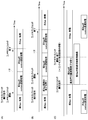
- FIG. 12A, 12B, and 12C show the operation of the processing unit 46 and the CDMA engine 48 in the context switch.
- FIG. 12A shows the operation (immediate context switch) of the processing unit 46 of the first embodiment.
- the processing unit 46 executes the pre-App process and the next App process
- the CDMA engine 48 executes the pre-App context evacuation process and the next App context setting process.
- FIG. 12B shows the operation of the processing unit 46 (context switch after all internal processing is completed) described in the modified example of the first embodiment.
- the start of the context save process is delayed by the time waiting for the end of the previous App process.
- the application is executed by using one of the context holding circuits by the context switching method shown in both FIGS. 12A and 12B. Inside, the context of the application to be executed next can be preset in the other context holding circuit. As a result, the time for waiting for the evacuation of the context and the completion of the setting (period 112 in FIGS. 12A and 12B) can be made almost zero.
- FIG. 12C shows the operation of the processing unit 46 of the third embodiment (context switch after completion of internal processing that cannot be mixed).
- Context switch start / end indicates that the reference destination is switched to a context holding circuit different from the previous one in order to execute the next application. For example, it indicates that the reference destination is switched from the first functional circuit 70a to the first functional circuit 70b.
- the CSDI engine 48 saves the context of the front application from the context holding circuit (for example, the first functional circuit 70a) of the front application to the main memory 22.
- FIG. 13 shows the configuration of the processing unit 46 of the fourth embodiment.
- the processing unit 46 of the fourth embodiment includes a plurality of functional blocks that execute internal processing that cannot be mixed between a plurality of applications.
- a functional block that executes internal processing that cannot be mixed between multiple applications is, for example, for (1) "processing content before and after in time and processing content of a function spatially connected to the periphery as a circuit". It may be a circuit that executes processing having a dependency relationship. Alternatively, (2) when internal processing premised on different settings of each application is input, the circuit may cause a failure of internal processing due to the settings of both applications not being common.
- the processing unit 46 shown in FIG. 13 includes a plurality of random logics 75 as an example of a functional block that executes internal processing that cannot be mixed between a plurality of applications.
- the processing unit 46 of FIG. 13 includes two random logics 75 (random logic 75a and random logic 75b), but may include three or more random logics 75.
- the processing unit 46 When the App switching timing is detected and the processing target in the processing unit 46 should be switched from the first application (for example, App A) to the second application (for example, App B), the processing unit 46 performs on-the-fly regarding the first application. Of the outstanding internal processing, the processing related to the second application and the internal processing that cannot be mixed are continuously executed by using one of the random logic 75 (for example, random logic 75a). Further, the processing unit 46 does not wait for the completion of the internal processing that cannot be mixed, and immediately starts the processing related to the second application by using the other random logic 75 (for example, the random logic 75b).
- the random logic 75 for example, random logic 75a
- SOC11 of the fourth embodiment it is not necessary to wait for the completion of the on-the-fly outstanding internal processing related to the first application and the internal processing that cannot be mixed with the processing related to the second application.
- the context switch execution instruction is given, the processing related to the second application can be started at an early stage, and the context switch can be realized at a higher speed.
- the processing unit 46 may simultaneously assign a plurality of applications to a plurality of multiplexed functional circuits, and the processing unit 46 may execute internal processing of the plurality of applications in parallel.
- the functional circuit is double-multiplexed and the number of applications to be processed in parallel is four (for example, App A to D)
- the two selected applications for example, App A and App B
- the remaining two applications for example, App C and App D
- the remaining two applications for example, App C and App D
- the processing unit 46 holds the context of the application A in the first functional circuit 70a and holds the context of the application B. It may be held in the first functional circuit 70b. Further, the processing unit 46 allocates the internal processing related to the Application A and the internal processing that cannot be mixed with the internal processing related to the Application B to the random logic 75a, and the internal processing related to the App B that cannot be mixed with the internal processing related to the App A. Internal processing may be assigned to random logic 75b.
- processing unit 46 shares both the internal processing related to App A and the internal processing that can be mixed with the internal processing related to App B, and the internal processing related to App B and the internal processing related to App A and the internal processing that can be mixed. It may be assigned to the arithmetic unit 76 and the work memory 77.
- the processing unit 46 since the processing unit 46 executes a plurality of applications at the same time instead of executing them in a time-division manner, the processing delay can be further suppressed. In addition, the number of times context switches occur can be suppressed. Further, the active rate (in other words, the activation rate) of the circuit included in the processing unit 46 is improved, and the performance of data processing can be improved.
- FIG. 14 shows the configuration of the processing unit 46 of the fifth embodiment.
- both the first functional circuit 70 that holds the context and the second functional circuit 71 that does not hold the context are multiplexed.
- the processing unit 46 of FIG. 14 includes four first functional circuits 70 and four second functional circuits 71, but the multiplexing of the first functional circuit 70 and the second functional circuit 71 is not limited to quadruple.
- the processing unit 46 assigns how many first function circuits 70 and second function circuits 71 to one application for each context switch. decide. Then, the processing unit 46 allocates one or more first functional circuits 70 and one or more second functional circuits 71 to each application to be executed.
- the performance requirements of each application or the number of first functional circuits 70 and second functional circuits 71 required by each application may be set in the processing unit 46 by the management software on the CPU 12.
- the processing unit 46 may assign each of the four applications (for example, Applications A to D) to a pair of one first functional circuit 70 and one second functional circuit 71. Further, when the data processing related to the application E requires four times the performance of the data processing related to the application A, as shown in FIG. 15B, the processing unit 46 has four second functional circuits 71 with respect to the application E. And one first functional circuit 70 may be assigned. When executing App E, the three first functional circuits 70 may be unused.
- the processing unit 46 may execute the processing by the allocation shown in FIG. 15A and the processing by the allocation shown in FIG. 15B in a time-division manner. In this case, by applying any of the context switching methods described in the first to fourth embodiments, the transition between the state of FIG. 15A and the state of FIG. 15B can be realized at high speed.
- the application is currently in operation (whether or not the application that holds the interface is being executed) and what kind of context (such as the identification information of the application) are shared among the multiplexed first functional circuits 70.
- An interface to be provided may be provided.
- the CSDI engine 48 connected to the processing unit 46 controls a plurality of first functional circuits 70 on behalf of the processing unit 46, and manages which App context is held in each first functional circuit 70. You may.
- any of the context switching methods described in the first to fourth embodiments may be executed for each application.
- the context switch may be executed at the timing when all the applications are aligned (for example, the timing when the internal processing of all the applications is completed). If only App A is switched to another App (for example, App F) in the state shown in FIG. 15A, and if the performance requirement of App F is equal to or less than the performance requirement of App A, the first corresponding to App A.
- the context switch may be executed only in the functional circuit 70 and the second functional circuit 71.
- the first functional circuit 70 and the second functional circuit 71 can be assigned to applications other than those shown in FIGS. 15A and 15B.
- an application occupying two or three second functional circuits 71 may be executed at the same time as another application.
- the first functional circuit 70 that holds the context was multiplexed.
- this configuration it is possible to save and set the context by overlapping during the processing of the application.
- This makes it possible to simplify the transfer capability of the CSDMA engine 48 and the system for inputting / outputting data (for example, bus fabric 100, scan chain 106, dedicated route 108, path 114).
- the vertical return period is 0.5 milliseconds
- the processing time of each application. Is 3.7 milliseconds.
- the context switch in less than 0.5 milliseconds.
- the possibility of multiplexing it may be executed in less than 3.7 milliseconds.
- the amount of data in the context is 50 MB
- a transfer capacity of 100 GB / sec or more is required to transfer within the vertical blanking interval.
- a transfer capacity of 13.5 GB / sec or more is sufficient.
- the save destination of the context is the main memory 22, but the memory that is the save destination of the context (in other words, the memory that saves the context) may be a memory different from the main memory 22. Further, the data retention characteristic of the memory to save the context may be volatile or non-volatile.
- the context saved in the memory is retained even if the power supply to the memory is cut when the processing unit 46 is paused / restarted such as suspend / hibernation. Will be done. As a result, the high-speed context switch described in the above embodiment can be used more effectively.
- the CPU 12, the processing unit 46 (GPU 14, video encoder 16, etc.), and the CDRM engine 48 are mounted on one hardware (SOC11).
- these functional blocks may be distributed and implemented on a plurality of hardware.
- the CDMA engine 48 of each embodiment may be realized as a data transfer device independent of the device on which the processing unit 46 is mounted.
- the technology of the present disclosure can be applied to a system or device that processes data.
Landscapes
- Engineering & Computer Science (AREA)
- Theoretical Computer Science (AREA)
- Software Systems (AREA)
- General Engineering & Computer Science (AREA)
- General Physics & Mathematics (AREA)
- Physics & Mathematics (AREA)
- Computer Hardware Design (AREA)
- Signal Processing (AREA)
- Computer Networks & Wireless Communication (AREA)
- Computing Systems (AREA)
- Stored Programmes (AREA)
- Multi Processors (AREA)
- Two-Way Televisions, Distribution Of Moving Picture Or The Like (AREA)
- Image Processing (AREA)
Priority Applications (3)
| Application Number | Priority Date | Filing Date | Title |
|---|---|---|---|
| CN202180007057.2A CN114787775A (zh) | 2020-02-03 | 2021-01-27 | 数据处理系统、数据转发装置以及上下文切换方法 |
| US17/795,043 US11789714B2 (en) | 2020-02-03 | 2021-01-27 | Data processing system, data transfer device, and context switching method |
| JP2021575749A JP7368511B2 (ja) | 2020-02-03 | 2021-01-27 | データ処理システム、データ転送装置およびコンテキストスイッチ方法 |
Applications Claiming Priority (2)
| Application Number | Priority Date | Filing Date | Title |
|---|---|---|---|
| JP2020-016144 | 2020-02-03 | ||
| JP2020016144 | 2020-02-03 |
Publications (1)
| Publication Number | Publication Date |
|---|---|
| WO2021157448A1 true WO2021157448A1 (ja) | 2021-08-12 |
Family
ID=77200629
Family Applications (1)
| Application Number | Title | Priority Date | Filing Date |
|---|---|---|---|
| PCT/JP2021/002880 Ceased WO2021157448A1 (ja) | 2020-02-03 | 2021-01-27 | データ処理システム、データ転送装置およびコンテキストスイッチ方法 |
Country Status (4)
| Country | Link |
|---|---|
| US (1) | US11789714B2 (https=) |
| JP (1) | JP7368511B2 (https=) |
| CN (1) | CN114787775A (https=) |
| WO (1) | WO2021157448A1 (https=) |
Families Citing this family (1)
| Publication number | Priority date | Publication date | Assignee | Title |
|---|---|---|---|---|
| US20230289212A1 (en) * | 2022-03-10 | 2023-09-14 | Nvidia Corporation | Flexible Migration of Executing Software Between Processing Components Without Need For Hardware Reset |
Citations (5)
| Publication number | Priority date | Publication date | Assignee | Title |
|---|---|---|---|---|
| JPH0683614A (ja) * | 1992-09-01 | 1994-03-25 | Matsushita Electric Ind Co Ltd | マイクロコンピュータ |
| JPH06180653A (ja) * | 1992-10-02 | 1994-06-28 | Hudson Soft Co Ltd | 割り込み処理方法および装置 |
| JP2003271399A (ja) * | 2002-01-09 | 2003-09-26 | Matsushita Electric Ind Co Ltd | プロセッサ及びプログラム実行方法 |
| JP2004185602A (ja) * | 2002-12-05 | 2004-07-02 | Internatl Business Mach Corp <Ibm> | 割込み時のプロセッサのアーキテクチャ状態の管理 |
| JP2006351013A (ja) * | 2005-06-15 | 2006-12-28 | Seiko Epson Corp | 電子装置において保存/リストア手順を行なうための方法及びシステム |
Family Cites Families (12)
| Publication number | Priority date | Publication date | Assignee | Title |
|---|---|---|---|---|
| JPS6180653A (ja) | 1984-09-28 | 1986-04-24 | Toshiba Corp | デイスクレコ−ド再生装置 |
| JPH0683614B2 (ja) | 1985-03-12 | 1994-10-26 | 井関農機株式会社 | コンバインに於ける刈取部の取付装置 |
| US5896141A (en) * | 1996-07-26 | 1999-04-20 | Hewlett-Packard Company | System and method for virtual device access in a computer system |
| US7904700B2 (en) * | 2008-03-10 | 2011-03-08 | International Business Machines Corporation | Processing unit incorporating special purpose register for use with instruction-based persistent vector multiplexer control |
| JP2012008767A (ja) * | 2010-06-24 | 2012-01-12 | Panasonic Corp | プロセッサ、再生装置及び処理装置 |
| US20120092351A1 (en) * | 2010-10-19 | 2012-04-19 | Apple Inc. | Facilitating atomic switching of graphics-processing units |
| CN102541769B (zh) * | 2010-12-13 | 2014-11-05 | 中兴通讯股份有限公司 | 一种存储器接口访问控制方法及装置 |
| US9392246B2 (en) * | 2011-04-28 | 2016-07-12 | Panasonic Intellectual Property Management Co., Ltd. | Recording medium, playback device, recording device, encoding method, and decoding method related to higher image quality |
| WO2015042684A1 (en) * | 2013-09-24 | 2015-04-02 | University Of Ottawa | Virtualization of hardware accelerator |
| US10031770B2 (en) * | 2014-04-30 | 2018-07-24 | Intel Corporation | System and method of delayed context switching in processor registers |
| US10565466B2 (en) * | 2016-03-14 | 2020-02-18 | Kabushiki Kaisha Toshiba | Image processor and image processing method |
| US11127107B2 (en) * | 2019-09-30 | 2021-09-21 | Intel Corporation | Apparatus and method for real time graphics processing using local and cloud-based graphics processing resources |
-
2021
- 2021-01-27 WO PCT/JP2021/002880 patent/WO2021157448A1/ja not_active Ceased
- 2021-01-27 CN CN202180007057.2A patent/CN114787775A/zh active Pending
- 2021-01-27 JP JP2021575749A patent/JP7368511B2/ja active Active
- 2021-01-27 US US17/795,043 patent/US11789714B2/en active Active
Patent Citations (5)
| Publication number | Priority date | Publication date | Assignee | Title |
|---|---|---|---|---|
| JPH0683614A (ja) * | 1992-09-01 | 1994-03-25 | Matsushita Electric Ind Co Ltd | マイクロコンピュータ |
| JPH06180653A (ja) * | 1992-10-02 | 1994-06-28 | Hudson Soft Co Ltd | 割り込み処理方法および装置 |
| JP2003271399A (ja) * | 2002-01-09 | 2003-09-26 | Matsushita Electric Ind Co Ltd | プロセッサ及びプログラム実行方法 |
| JP2004185602A (ja) * | 2002-12-05 | 2004-07-02 | Internatl Business Mach Corp <Ibm> | 割込み時のプロセッサのアーキテクチャ状態の管理 |
| JP2006351013A (ja) * | 2005-06-15 | 2006-12-28 | Seiko Epson Corp | 電子装置において保存/リストア手順を行なうための方法及びシステム |
Also Published As
| Publication number | Publication date |
|---|---|
| US11789714B2 (en) | 2023-10-17 |
| US20230090585A1 (en) | 2023-03-23 |
| JPWO2021157448A1 (https=) | 2021-08-12 |
| CN114787775A (zh) | 2022-07-22 |
| JP7368511B2 (ja) | 2023-10-24 |
Similar Documents
| Publication | Publication Date | Title |
|---|---|---|
| JP4322232B2 (ja) | 情報処理装置、プロセス制御方法、並びにコンピュータ・プログラム | |
| US10740146B2 (en) | Migrating virtual machines between compute systems by transmitting programmable logic accelerator state | |
| JP4322259B2 (ja) | マルチプロセッサシステムにおけるローカルメモリへのデータアクセスを同期化する方法および装置 | |
| JP6086230B2 (ja) | 中央演算装置、情報処理装置、および仮想コア内レジスタ値取得方法 | |
| JP4674729B2 (ja) | グラフィックス処理装置、グラフィックスライブラリモジュール、およびグラフィックス処理方法 | |
| US7454756B2 (en) | Method, apparatus and system for seamlessly sharing devices amongst virtual machines | |
| US5127098A (en) | Method and apparatus for the context switching of devices | |
| JP4550878B2 (ja) | グラフィックス処理装置 | |
| US8928677B2 (en) | Low latency concurrent computation | |
| JP2010050970A (ja) | 中央処理装置と画像処理装置との間で通信するための機器および方法 | |
| JP2024538279A (ja) | ダイレクトメモリアクセスコマンドのハードウェア管理 | |
| JP2006099332A (ja) | 情報処理装置、プロセス制御方法、並びにコンピュータ・プログラム | |
| TWI457828B (zh) | 執行緒陣列粒化執行的優先權計算 | |
| JP7368511B2 (ja) | データ処理システム、データ転送装置およびコンテキストスイッチ方法 | |
| US8108879B1 (en) | Method and apparatus for context switching of multiple engines | |
| CN115756730A (zh) | 虚拟机调度方法、装置、gpu及电子设备 | |
| US20250173198A1 (en) | Data processing system | |
| CN114691297A (zh) | 一种信息读写方法、电子设备、分布式系统以及程序产品 | |
| CN119440735B (zh) | 基于ARM VHE的微内核Hypervisor的虚拟机暂停处理方法 | |
| JP2009175960A (ja) | 仮想マルチプロセッサシステム | |
| US6418540B1 (en) | State transfer with throw-away thread | |
| US12131199B2 (en) | Workgroup synchronization and processing | |
| WO2023236479A1 (zh) | 用于执行任务调度的方法及其相关产品 | |
| CN111381887B (zh) | 在mvp处理器中进行图像运动补偿的方法、装置及处理器 | |
| JP2000227895A (ja) | 画像データ転送装置および画像データ転送方法 |
Legal Events
| Date | Code | Title | Description |
|---|---|---|---|
| 121 | Ep: the epo has been informed by wipo that ep was designated in this application |
Ref document number: 21751018 Country of ref document: EP Kind code of ref document: A1 |
|
| ENP | Entry into the national phase |
Ref document number: 2021575749 Country of ref document: JP Kind code of ref document: A |
|
| NENP | Non-entry into the national phase |
Ref country code: DE |
|
| 122 | Ep: pct application non-entry in european phase |
Ref document number: 21751018 Country of ref document: EP Kind code of ref document: A1 |