WO2021157084A1 - アンテナ装置及び無線通信装置 - Google Patents
アンテナ装置及び無線通信装置 Download PDFInfo
- Publication number
- WO2021157084A1 WO2021157084A1 PCT/JP2020/004928 JP2020004928W WO2021157084A1 WO 2021157084 A1 WO2021157084 A1 WO 2021157084A1 JP 2020004928 W JP2020004928 W JP 2020004928W WO 2021157084 A1 WO2021157084 A1 WO 2021157084A1
- Authority
- WO
- WIPO (PCT)
- Prior art keywords
- antenna
- frequency
- antenna device
- monopole antenna
- ground member
- Prior art date
- Legal status (The legal status is an assumption and is not a legal conclusion. Google has not performed a legal analysis and makes no representation as to the accuracy of the status listed.)
- Ceased
Links
Images






Classifications
-
- H—ELECTRICITY
- H01—ELECTRIC ELEMENTS
- H01Q—ANTENNAS, i.e. RADIO AERIALS
- H01Q5/00—Arrangements for simultaneous operation of antennas on two or more different wavebands, e.g. dual-band or multi-band arrangements
- H01Q5/30—Arrangements for providing operation on different wavebands
- H01Q5/378—Combination of fed elements with parasitic elements
Definitions
- the present invention relates to an antenna device and a wireless communication device.
- a small wireless communication device exemplified by a smartphone is used.
- an antenna device that can be housed in a small housing is used (see, for example, Patent Documents 1-4).
- wireless communication devices have been made smaller, thinner, and have larger screens, as illustrated by smartphones, so the space for accommodating the antenna device in the housing is decreasing.
- the housing is often made of metal for the purpose of improving the design and ensuring the strength of the housing, and the characteristics of the antenna device tend to deteriorate. If the matching circuit is connected in such an environment, the band of the antenna device may be further narrowed.
- One aspect of the disclosed technology is to provide an antenna device and a wireless communication device capable of suppressing narrowing of the band due to the connection of matching circuits.
- the antenna device includes a feeding point, a ground member grounded, a first monopole antenna, and a second monopole antenna, and the first monopole antenna includes the second monopole antenna and the ground.
- the second monopole antenna is arranged between the members, one end is connected to the feeding point, has an electric length of 3/4 of the radio wave wavelength of the first frequency, and one end is connected to the ground member.
- it is capacitively coupled to the first monopole antenna through a gap, has an electric length of 1/4 of the second frequency lower than the first frequency, and has electricity at the second frequency of the first monopole antenna.
- the length is set to be 1/4 of the wavelength of the radio wave of the second frequency.
- the disclosed technology can suppress the narrowing of the band due to the connection of the matching circuit.
- FIG. 1 is a diagram showing an example of an antenna device according to an embodiment.
- FIG. 2 is a diagram illustrating the configuration of a smartphone.
- FIG. 3 is a diagram showing an implementation example when the antenna device according to the embodiment is mounted on the smartphone illustrated in FIG.
- FIG. 4 is a first diagram schematically showing variations of a matching circuit.
- FIG. 5 is a second diagram schematically showing variations of the matching circuit.
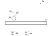
- FIG. 6 is a diagram showing an example of an antenna device according to a comparative example.
- FIG. 7 is a diagram showing an example in which the antenna device according to the comparative example is mounted on the smartphone illustrated in FIG.
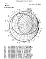
- FIG. 8 is a Smith chart illustrating the characteristics of the antenna device according to the comparative example in the free space.
- FIG. 1 is a diagram showing an example of an antenna device according to an embodiment.
- FIG. 2 is a diagram illustrating the configuration of a smartphone.
- FIG. 3 is a diagram showing an implementation example when the antenna device according to the embodiment is mounted on
- FIG. 9 is a Smith chart illustrating the characteristics of the antenna device according to the comparative example when mounted on the smartphone illustrated in FIG.
- FIG. 10 is a diagram illustrating a state in which the second antenna, which is a non-feeding antenna, is removed from the antenna device according to the comparative example.
- FIG. 11 is a diagram schematically showing a Smith chart illustrating the characteristics of the antenna device illustrated in FIG. 10 when mounted on the smartphone illustrated in FIG. 2.
- FIG. 12 is a diagram schematically showing a Smith chart illustrating the characteristics of the antenna device according to the comparative example when mounted on the smartphone illustrated in FIG. 2.
- FIG. 13 is a Smith chart illustrating the characteristics of the antenna device according to the embodiment when mounted on the smartphone illustrated in FIG. 2.
- FIG. 11 is a diagram schematically showing a Smith chart illustrating the characteristics of the antenna device illustrated in FIG. 10 when mounted on the smartphone illustrated in FIG. 2.
- FIG. 12 is a diagram schematically showing a Smith chart illustrating the characteristics of the antenna device according to the comparative example
- FIG. 14 is a diagram showing an example of the antenna device according to the first modification.
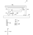
- FIG. 15 is a diagram showing an example of the antenna device according to the second modification.
- FIG. 16 is a diagram showing an implementation example when the antenna device according to the second modification is mounted on the smartphone illustrated in FIG.
- FIG. 17 is a Smith chart illustrating the characteristics of the antenna device according to the second modification when mounted on the smartphone illustrated in FIG.
- the antenna device according to the embodiment includes, for example, the following configuration.
- the antenna device according to this embodiment is It is equipped with a feeding point, a grounded ground member, a first monopole antenna, and a second monopole antenna.
- the first monopole antenna is arranged between the second monopole antenna and the ground member, one end of which is connected to the feeding point, and has an electric length of 3/4 of the wavelength of the radio wave of the first frequency.
- One end of the second monopole antenna is connected to the ground member, and is capacitively coupled to the first monopole antenna through a gap, and has an electric length of 1/4 of the second frequency lower than the first frequency. death, The electric length of the first monopole antenna at the second frequency is set to be 1/4 of the wavelength of the radio wave of the second frequency.
- the first monopole antenna is a monopole antenna, it can operate with radio waves of the first frequency if its electrical length is 1/4 of the wavelength of the first frequency.
- the electric length of the first monopole antenna is set to 3/4 of the wavelength of the radio wave of the first frequency, and the impedance of the first monopole antenna is appropriately set, so that the first monopole at the second frequency is used. It is possible to make the electric length of the pole antenna 1/4 of the wavelength of the radio wave of the second frequency.
- a first monopole antenna can resonate with radio waves of the second frequency, it does not transmit radio waves of the second frequency with a communicable output.
- the antenna device according to the present embodiment can suppress the narrowing of the band of the antenna device even if the matching circuit is connected to the antenna device.
- the first monopole antenna is arranged so that the distance between the part on the side opposite to one end and the ground member is 1/50 or less of the wavelength of the radio wave of the first frequency. By doing so, the impedance of the first monopole antenna may be set. Further, in the antenna device according to the first modification of the present embodiment, a part of the first monopole antenna opposite to the one end and the ground member are connected by a lumped constant circuit including a coil and a capacitor. By doing so, the impedance of the first monopole antenna may be set.
- the part on the opposite side to the one end may be an open end or a part other than the open end.
- the antenna device according to the second modification of the present embodiment may have the following configuration.
- the antenna device according to the second modification is It includes a feeding point, a grounded ground member, a first monopole antenna, a second monopole antenna, and a branch conductor.
- the first monopole antenna is arranged between the second monopole antenna and the ground member, one end of which is connected to the feeding point, and has an electric length of 1/4 of the wavelength of the radio wave of the first frequency. death,
- One end of the second monopole antenna is connected to the ground member, and is capacitively coupled to the first monopole antenna through a gap, and has an electric length of 1/4 of the second frequency lower than the first frequency.
- One end of the branch conductor is connected to the first monopole antenna, and at least a part thereof is arranged at a distance of 1/50 or less of the wavelength of the radio wave of the first frequency from the ground member, and the branch conductor at the second frequency.
- the electric length of the branch conductor is 1/4 of the wavelength of the radio wave of the second frequency.
- a branch conductor connected to the first monopole antenna is provided.
- the electric length of the branched conductor at the second frequency is set to 1/4 of the wavelength of the radio wave of the second frequency.
- the branched conductor can resonate with the radio wave of the second frequency, while being able to resonate.
- the second frequency radio wave is not transmitted at a communicable output.
- the branch conductor By providing such a branch conductor, even if the matching circuit is connected between the first monopole antenna and the feeding point as in the antenna device according to the above embodiment, the narrowing of the band of the antenna device can be suppressed. Can be done. Further, by providing the branch conductor, the electric length of the first monopole antenna can be made shorter than that of the first monopole antenna of the antenna device according to the embodiment.
- a matching circuit including a capacitor may be connected between the first monopole antenna and the feeding point.
- the antenna device according to the embodiment and each modification can suppress the narrowing of the band of the antenna device due to the connection of the matching circuit.
- the antenna device can be mounted on a wireless communication device, for example.
- Examples of the wireless communication device include smartphones, tablet terminals, wearable computers, mobile phones, notebook-type personal computers, and the like.
- FIG. 1 is a diagram showing an example of an antenna device according to an embodiment.
- the antenna device 1 exemplified in FIG. 1 includes a feeding point 11, a feeding line 12, a first antenna 13, a second antenna 14, a ground wire 15, and a ground member 16.
- the right side of FIG. 1 is referred to as the + X direction
- the left side is referred to as the ⁇ X direction
- the upper side is referred to as the + Y direction
- the lower side is referred to as the ⁇ Y direction.
- the ground member 16 is a grounded plate-shaped member.
- the ground member 16 is provided with, for example, a feeding point 11 that supplies power to the first antenna 13.
- the ground member 16 may be a printed circuit board on which various electronic components are mounted.
- the first antenna 13 is a monopole antenna having one end connected to the feeding point 11 via a feeding line 12 and the other end having an open end.
- the first antenna 13 has an electric length of 3/4 of the wavelength of the radio wave of the first frequency.
- the first frequency is, for example, 5 GHz.
- the first antenna 13 is provided between the second antenna 14 and the ground member 16.
- the first antenna 13 is bent and formed so that such an electric length can be secured in a limited space. Further, at least a part of the first antenna 13 is provided so as to be close to the ground member 16.
- the first antenna 13 illustrated in FIG. 1 includes an eleventh conductor portion 131, a twelfth conductor portion 132, a thirteenth conductor portion 133, and a fourteenth conductor portion 134.
- One end of the eleventh conductor portion 131 is connected to the feeding point 11 via the feeding line 12, and the other end extends in the + Y direction.
- the twelfth conductor portion 132 extends parallel to the ground member 16 from the end portion of the eleventh conductor portion 131 in the + Y direction toward the + X direction.
- the thirteenth conductor portion 133 extends parallel to the eleventh conductor portion 131 from the + X side end portion of the twelfth conductor portion 132 in the ⁇ Y direction.
- the 14th conductor portion 134 extends parallel to the ground member 16 from the ⁇ Y side end of the 13th conductor portion 133 toward the + X side. That is, of the first antenna 13, the 14th conductor portion 134 is close to the ground member 16.
- the distance D1 between the 14th conductor portion 134 and the ground member 16 is, for example, 1/50 or less of the wavelength of the radio wave of the first frequency. However, the 14th conductor portion 134 does not come into contact with the ground member 16.
- the second antenna 14 is a non-feeding monopole antenna having one end connected to the ground member 16 via the ground wire 15 and the other end having an open end.
- the second antenna 14 is capacitively coupled to the first antenna 13 at least in part, and has an electric length of 1/4 of the wavelength of the radio wave of the second frequency lower than the first frequency.
- the second frequency is, for example, 2.4 GHz.
- the second antenna 14 illustrated in FIG. 1 includes a 21st conductor portion 141 and a 22nd conductor portion 142.
- the 21st conductor portion 141 extends from the ground member 16 via the ground wire 15 in the + Y direction.
- the 22nd conductor portion 142 extends parallel to the ground member 16 from the end portion of the 21st conductor portion 141 in the + Y direction toward the ⁇ X direction.
- the distance D2 between the 22nd conductor portion 142 of the second antenna 14 and the 12th conductor portion 132 of the first antenna 13 is, for example, 1/50 or less of the wavelength of the radio wave of the first frequency. However, the first antenna 13 and the second antenna 14 do not come into contact with each other.
- the electric length of the first antenna 13 is increased.
- the wavelength of the radio wave of two frequencies can be set to 1/4, and the impedance of the first antenna 13 at the second frequency can be made sufficiently lower than that of the second antenna 14.
- the impedance of the first antenna 13 at the second frequency is set so that, for example, the first antenna 13 can resonate with the radio wave of the second frequency, while the first antenna 13 does not transmit the radio wave of the second frequency. Will be done.
- the distance D1 between the 14th conductor portion 134 and the ground member 16 and the length of the 14th conductor portion 134 are such that the electric length of the first antenna 13 becomes 1/4 of the wavelength of the radio wave of the second frequency.
- the first antenna 13 is adjusted so as not to transmit the radio wave of the second frequency.
- FIG. 2 is a diagram illustrating the configuration of a smartphone.
- FIG. 2 illustrates a state in which the cover on the back side of the smartphone 300 is opened.
- the smartphone 300 is formed in a plate shape and has a predetermined thickness.
- a metal frame 310 made of metal surrounds the side surface of the smartphone 300 formed in a plate shape.
- a base substrate 320 on which various electronic components are mounted is provided in the region surrounded by the metal frame 310.
- the side surface of the base substrate 320 facing the metal frame 310 is, for example, grounded.
- the smartphone 300 is a portable wireless communication device equipped with a Central Processing Unit (CPU), a memory, and the like.
- the antenna device 1 is provided, for example, in the region surrounded by the ellipse R1 in FIG.
- FIG. 3 is a diagram showing an implementation example when the antenna device according to the embodiment is mounted on the smartphone illustrated in FIG. FIG. 3 illustrates an enlarged view of the vicinity of the ellipse R in FIG.
- the base substrate 320 is used as the ground member 16 of the antenna device 1.
- a matching circuit 17 is provided between the feeding point 11 and the first antenna 13.
- the metal frame 310 is present in the vicinity of the antenna device 1.
- Both the matching circuit 17 illustrated in FIG. 4 and the matching circuit 17a illustrated in FIG. 5 include a capacitor 171 connected in series with the first antenna 13. Further, both the matching circuit 17 and the matching circuit 17a include a plurality of coils 172.
- FIG. 6 is a diagram showing an example of an antenna device according to a comparative example.
- the same components as those in the embodiment are designated by the same reference numerals, and the description thereof will be omitted.
- the antenna device 5 illustrated in FIG. 6 is different from the antenna device 1 according to the embodiment in that the first antenna 53 and the second antenna 54 are provided in place of the first antenna 13 and the second antenna 14.
- the first antenna 53 is a monopole antenna having one end connected to the feeding point 11 via a feeding line 12 and the other end having an open end.
- the first antenna 53 includes an eleventh conductor portion 531 and a twelfth conductor portion 532.
- One end of the eleventh conductor portion 531 is connected to the feeding point 11 via the feeding line 12, and the other end extends in the + Y direction.
- the twelfth conductor portion 532 extends parallel to the ground member 16 from the end portion of the first conductor portion 531 in the + Y direction toward the + X direction.
- the second antenna 54 is a non-feeding monopole antenna having one end connected to the ground member 16 via the ground wire 15 and the other end having an open end.
- the second antenna 54 includes a 21st conductor portion 541 and a 22nd conductor portion 542.
- the 21st conductor portion 541 extends from the ground member 16 via the ground wire 15 in the + Y direction.
- the 22nd conductor portion 542 extends parallel to the ground member 16 from the end portion of the 21st conductor portion 541 in the + Y direction in the ⁇ X direction.
- the distance D3 between the + X side end (open end) of the 12th conductor portion 532 of the first antenna 53 and the ⁇ X side end (open end) of the 22nd conductor portion 542 of the second antenna 54 is, for example, , It is 1/50 or less of the wavelength of the radio wave of the first frequency.
- the second antenna 54 can resonate at the second frequency by capacitively coupling the open end of the first antenna 53 and the open end of the second antenna 54.
- the first antenna 53 is not arranged between the second antenna 54 and the ground member 16. Further, in the antenna device 5 according to the comparative example, unlike the antenna device 1 according to the embodiment, the first antenna 53 does not have the 14th conductor portion 134 close to the ground member 16. That is, in the antenna device 5 according to the comparative example, the first antenna 53 does not have a region close to the ground member 16.
- FIG. 7 is a diagram showing an example in which the antenna device according to the comparative example is mounted on the smartphone illustrated in FIG.
- FIG. 7 illustrates an enlarged view of the vicinity of the ellipse R in FIG.
- the base substrate 320 is used as the ground member 16 of the antenna device 5.
- a matching circuit 17 is provided between the feeding point 11 and the first antenna 53.
- the metal frame 310 is present in the vicinity of the antenna device 5.
- FIG. 8 is a Smith chart illustrating the characteristics of the antenna device according to the comparative example in the free space.
- FIG. 9 is a Smith chart illustrating the characteristics of the antenna device according to the comparative example when mounted on the smartphone illustrated in FIG. 2. That is, in FIG. 9, a matching circuit 17 and a matching circuit 17a are connected between the first antenna 53 of the antenna device 5 and the feeding point 11. Comparing FIGS. 8 and 9, it can be understood that the distance between points 1 to 3 indicated by the inverted triangle is wider when mounted on the smartphone 300 than in the case of free space.
- Table 1 below is a table illustrating the relationship between the presence / absence of the matching circuit 17 (or matching circuit 17a) and the specific bandwidth.
- FIG. 10 is a diagram illustrating a state in which the second antenna, which is a non-feeding antenna, is removed from the antenna device according to the comparative example.
- FIG. 11 is a diagram schematically showing a Smith chart illustrating the characteristics of the antenna device exemplified in FIG.
- FIG. 12 is a diagram schematically illustrating a Smith chart illustrating the characteristics of the antenna device according to the comparative example illustrated in FIG. Both FIGS. 11 and 12 exemplify the characteristics of the antenna device 5a and the antenna device 5 in a state of being housed in a metal housing.
- FIGS. 11 and 12 exemplify the characteristics of the antenna device 5a and the antenna device 5 in a state of being housed in a metal housing.
- the first frequency is represented by “f1” and the second frequency is represented by “f2". Further, in FIGS. 11 and 12, among the bands of the first frequency and the second frequency, the high frequency band is referred to as “High”, the middle frequency band is referred to as “Middle”, and the low frequency band is referred to as “Low”.
- the band of the second frequency draws a circle starting from the lower right (1/8 or less of the wavelength of the first frequency) on the Smith chart as illustrated in FIG. .. Therefore, as illustrated in FIG. 11, the high frequency band of the second frequency is located on the lower side (capacitance side) of the Smith chart than the low frequency band.
- the low frequency band is located below the Smith chart (capacitance side) rather than the high frequency band at the second frequency.
- the Smith chart when a capacitor is connected in series with the antenna device, the lower frequency moves more counterclockwise on the constant resistance circle than the higher frequency. Therefore, when the matching circuit 17 and the matching circuit 17a are connected to the antenna device 5 in the state illustrated in FIG. 12 (that is, when a capacitor in series is connected to the first antenna 53), the second frequency is high. The interval on the Smith chart from the range to the low range becomes wider.
- the band of the antenna is likely to be narrowed, and the matching circuit 17 is attached to the antenna device 5.
- the matching circuit 17a is connected to the antenna device 5, the band of the antenna device 5 is further narrowed.
- FIG. 13 is a Smith chart illustrating the characteristics of the antenna device according to the embodiment when mounted on the smartphone illustrated in FIG. 2.
- the point indicated by "1" in the inverted triangle is from the point indicated by "3" in the inverted triangle (high frequency range of the second frequency).
- the matching circuit 17 or the matching circuit 17a is connected to the antenna device 1 (that is, when a capacitor in series is connected to the first antenna 13)
- the high to low frequencies of the second frequency are used.
- the interval on the Smith chart to is narrowed.
- the antenna device 1 can suppress the narrowing of the band due to the connection of the matching circuit 17 and the matching circuit 17a.
- Table 2 below is a table comparing the embodiment and the comparative example with respect to the relationship between the presence / absence of the matching circuit 17 (or the matching circuit 17a) and the specific bandwidth. As can be understood by referring to Table 2 below, the antenna device 1 according to the embodiment has a narrower band than the antenna device 5 according to the comparative example.
- the electric length of the first antenna 13 is set to 3/4 of the wavelength of the first frequency. Since the first antenna 13 is a monopole antenna, it can operate with radio waves of the first frequency if its electric length is set to 1/4 of the wavelength of the first frequency. However, in the present embodiment, the electric length of the first antenna 13 is set to 3/4 of the radio wave of the first frequency, so that the electric length of the first antenna 13 at the second frequency is 1 of the wavelength of the radio wave of the second frequency. It becomes possible to make it / 4.
- the impedance of the first antenna 13 at the second frequency is set to be sufficiently smaller than the impedance of the second antenna 14 at the second frequency, so that the first antenna 13 can resonate with the radio waves of the second frequency.
- the first antenna 13 does not transmit the radio wave of the second frequency with a communicable output.
- FIG. 14 is a diagram showing an example of the antenna device according to the first modification.
- the length of the 13th conductor portion 133a of the first antenna 13a is shorter than that of the 13th conductor portion 133 of the first antenna 13 in the embodiment. Therefore, the 14th conductor portion 134 and the ground member 16 are separated from each other as compared with the case of the antenna device 1.
- the open end of the 14th conductor portion 134 and the ground member 16 are connected by a lumped constant circuit 135.
- the lumped constant circuit 135 is a circuit in which a coil 1351 and a capacitor 1352 are connected in series.
- the capacitance of the coil 1351 may be 0.5 pF and the inductance of the coil 1351 may be 1.5 nH.
- the antenna device 1a Similarly to the antenna device 1, the antenna device 1a according to the first modification also has the electric length of the first antenna 13 set to 1/4 of the wavelength of the radio wave of the second frequency, and the first antenna 13 at the second frequency.
- the impedance of the second antenna 14 can be made sufficiently lower than that of the second antenna 14. As a result, the antenna device 1a can suppress the narrowing of the band by connecting the matching circuit 17 and the matching circuit 17a, similarly to the antenna device 1.
- FIG. 15 is a diagram showing an example of the antenna device according to the second modification.
- the antenna device 1b according to the second modification has a first antenna 13b and a second antenna 14.
- the first antenna 13b does not include the 13th conductor portion 133 and the 14th conductor portion 134, unlike the first antenna according to the embodiment.
- the first antenna 13b has an electric length of 1/4 of the wavelength of the radio wave of the first frequency. That is, the electric length of the first antenna 13b is shorter than the electric length of the first antenna 13 of the antenna device 1.
- the 11th conductor portion 131a is connected to the feeding point 11 via the feeding line 12 at an intermediate portion M thereof.
- the distance between the ⁇ Y side end portion (the end portion on the ground member 16 side) of the 11th conductor portion 131 and the ground member 16 may be, for example, 1/50 or less of the wavelength of the first frequency. However, the eleventh conductor portion 131 does not come into contact with the ground member 16.
- the antenna device 1b includes a branch conductor 18.
- the branch conductor 18 is a conductor in which one end is connected to the ⁇ Y side end of the 11th conductor portion 131 of the first antenna 13b and extends in the + X direction in parallel with the ground member 16.
- the distance between the branch conductor 18 and the ground member 16 is 1/50 or less of the wavelength of the first frequency. However, the branch conductor 18 does not come into contact with the ground member 16.
- the electrical length of the branch conductor 18 is set to 1/4 of the wavelength of the radio wave of the second frequency, and the second The impedance of the branch conductor 18 at a frequency can be made sufficiently lower than that of the second antenna 14.
- the impedance of the branch conductor 18 at the second frequency is set so that, for example, the branch conductor 18 can resonate with the radio wave of the second frequency, while the branch conductor 18 does not transmit the radio wave of the second frequency.
- the distance D4 between the branch conductor 18 and the ground member 16 and the length of the branch conductor 18 are such that the electrical length of the branch conductor 18 is 1/4 of the wavelength of the radio wave of the second frequency, and the branch conductor 18 is It is adjusted so that the radio wave of the second frequency is not transmitted.
- FIG. 16 is a diagram showing an implementation example when the antenna device according to the second modification is mounted on the smartphone illustrated in FIG.
- FIG. 16 an enlarged view of the vicinity of the ellipse R in FIG. 2 is illustrated.
- the base substrate 320 is used as the ground member 16 of the antenna device 1b.
- a matching circuit 17 is provided between the feeding point 11 and the first antenna 13b.
- the metal frame 310 is present in the vicinity of the antenna device 1b.
- FIG. 17 is a Smith chart illustrating the characteristics of the antenna device according to the second modification when mounted on the smartphone illustrated in FIG.
- the point indicated by "1" in the inverted triangle is from the point indicated by "3" in the inverted triangle (high frequency range of the second frequency).
- Table 3 below is a table comparing the embodiment, the second modification, and the comparative example with respect to the relationship between the presence / absence of the matching circuit 17 (or the matching circuit 17a) and the specific bandwidth.
- the antenna device according to the embodiment and the second modification has a smaller band narrowing than the antenna device 5 according to the comparative example.
Landscapes
- Details Of Aerials (AREA)
- Support Of Aerials (AREA)
Priority Applications (2)
| Application Number | Priority Date | Filing Date | Title |
|---|---|---|---|
| JP2021575578A JP7536803B2 (ja) | 2020-02-07 | 2020-02-07 | アンテナ装置及び無線通信装置 |
| PCT/JP2020/004928 WO2021157084A1 (ja) | 2020-02-07 | 2020-02-07 | アンテナ装置及び無線通信装置 |
Applications Claiming Priority (1)
| Application Number | Priority Date | Filing Date | Title |
|---|---|---|---|
| PCT/JP2020/004928 WO2021157084A1 (ja) | 2020-02-07 | 2020-02-07 | アンテナ装置及び無線通信装置 |
Publications (1)
| Publication Number | Publication Date |
|---|---|
| WO2021157084A1 true WO2021157084A1 (ja) | 2021-08-12 |
Family
ID=77199813
Family Applications (1)
| Application Number | Title | Priority Date | Filing Date |
|---|---|---|---|
| PCT/JP2020/004928 Ceased WO2021157084A1 (ja) | 2020-02-07 | 2020-02-07 | アンテナ装置及び無線通信装置 |
Country Status (2)
| Country | Link |
|---|---|
| JP (1) | JP7536803B2 (https=) |
| WO (1) | WO2021157084A1 (https=) |
Cited By (1)
| Publication number | Priority date | Publication date | Assignee | Title |
|---|---|---|---|---|
| JP2023118190A (ja) * | 2022-02-15 | 2023-08-25 | Fcnt株式会社 | 無線端末 |
Citations (5)
| Publication number | Priority date | Publication date | Assignee | Title |
|---|---|---|---|---|
| JP2004064282A (ja) * | 2002-07-26 | 2004-02-26 | Sansei Denki Kk | デュアルバンドアンテナおよびその構成方法、並びに3バンドアンテナ |
| WO2006090673A1 (ja) * | 2005-02-24 | 2006-08-31 | Matsushita Electric Industrial Co., Ltd. | 携帯無線機 |
| JP2009124355A (ja) * | 2007-11-13 | 2009-06-04 | Furukawa Electric Co Ltd:The | 平行2線アンテナ |
| JP2013059108A (ja) * | 2012-11-21 | 2013-03-28 | Toshiba Corp | 多共振アンテナ装置とこのアンテナ装置を備えた電子機器 |
| JP2013229823A (ja) * | 2012-04-26 | 2013-11-07 | Toshiba Corp | アンテナ装置とこのアンテナ装置を備えた電子機器 |
Family Cites Families (2)
| Publication number | Priority date | Publication date | Assignee | Title |
|---|---|---|---|---|
| JP3655234B2 (ja) * | 2001-11-30 | 2005-06-02 | 株式会社東芝 | アンテナ装置 |
| JP2004201278A (ja) * | 2002-12-06 | 2004-07-15 | Sharp Corp | パターンアンテナ |
-
2020
- 2020-02-07 WO PCT/JP2020/004928 patent/WO2021157084A1/ja not_active Ceased
- 2020-02-07 JP JP2021575578A patent/JP7536803B2/ja active Active
Patent Citations (5)
| Publication number | Priority date | Publication date | Assignee | Title |
|---|---|---|---|---|
| JP2004064282A (ja) * | 2002-07-26 | 2004-02-26 | Sansei Denki Kk | デュアルバンドアンテナおよびその構成方法、並びに3バンドアンテナ |
| WO2006090673A1 (ja) * | 2005-02-24 | 2006-08-31 | Matsushita Electric Industrial Co., Ltd. | 携帯無線機 |
| JP2009124355A (ja) * | 2007-11-13 | 2009-06-04 | Furukawa Electric Co Ltd:The | 平行2線アンテナ |
| JP2013229823A (ja) * | 2012-04-26 | 2013-11-07 | Toshiba Corp | アンテナ装置とこのアンテナ装置を備えた電子機器 |
| JP2013059108A (ja) * | 2012-11-21 | 2013-03-28 | Toshiba Corp | 多共振アンテナ装置とこのアンテナ装置を備えた電子機器 |
Cited By (2)
| Publication number | Priority date | Publication date | Assignee | Title |
|---|---|---|---|---|
| JP2023118190A (ja) * | 2022-02-15 | 2023-08-25 | Fcnt株式会社 | 無線端末 |
| JP7734605B2 (ja) | 2022-02-15 | 2025-09-05 | Fcnt合同会社 | 無線端末 |
Also Published As
| Publication number | Publication date |
|---|---|
| JP7536803B2 (ja) | 2024-08-20 |
| JPWO2021157084A1 (https=) | 2021-08-12 |
Similar Documents
| Publication | Publication Date | Title |
|---|---|---|
| JP5162012B1 (ja) | アンテナ装置とこのアンテナ装置を備えた電子機器 | |
| US9300055B2 (en) | Mobile device with two antennas and antenna switch modules | |
| US20150263430A1 (en) | Antenna structure | |
| US10008765B2 (en) | Antenna structure and wireless communication device using same | |
| US11095032B2 (en) | Antenna structure | |
| US10522902B1 (en) | Antenna structure | |
| US20200328520A1 (en) | Antenna and Electronic Device | |
| US11355847B2 (en) | Antenna structure | |
| CN211350957U (zh) | 天线及具有其的移动终端 | |
| US10224612B1 (en) | Mobile device | |
| US11329382B1 (en) | Antenna structure | |
| US10727588B2 (en) | Mobile device | |
| JPWO2013047033A1 (ja) | アンテナ装置及びアンテナの実装方法 | |
| CN103703614A (zh) | 天线装置以及天线的安装方法 | |
| WO2021157084A1 (ja) | アンテナ装置及び無線通信装置 | |
| US20250174877A1 (en) | Communication device | |
| US20140340277A1 (en) | Communication device and antenna element therein | |
| US12183994B2 (en) | Antenna structure | |
| CN207638003U (zh) | 天线装置及电子设备 | |
| US11011855B2 (en) | Antenna system | |
| US11342670B1 (en) | Antenna structure | |
| EP2752939A1 (en) | Communication device and antenna element therein | |
| US10826178B2 (en) | Multi-band antenna | |
| CN116487868B (zh) | 天线结构与电子装置 | |
| US9812769B2 (en) | Antenna apparatus |
Legal Events
| Date | Code | Title | Description |
|---|---|---|---|
| 121 | Ep: the epo has been informed by wipo that ep was designated in this application |
Ref document number: 20917906 Country of ref document: EP Kind code of ref document: A1 |
|
| ENP | Entry into the national phase |
Ref document number: 2021575578 Country of ref document: JP Kind code of ref document: A |
|
| NENP | Non-entry into the national phase |
Ref country code: DE |
|
| 122 | Ep: pct application non-entry in european phase |
Ref document number: 20917906 Country of ref document: EP Kind code of ref document: A1 |