WO2021153071A1 - ブレーキ解放機構、ブレーキ付モータ及び巻上機 - Google Patents
ブレーキ解放機構、ブレーキ付モータ及び巻上機 Download PDFInfo
- Publication number
- WO2021153071A1 WO2021153071A1 PCT/JP2020/047138 JP2020047138W WO2021153071A1 WO 2021153071 A1 WO2021153071 A1 WO 2021153071A1 JP 2020047138 W JP2020047138 W JP 2020047138W WO 2021153071 A1 WO2021153071 A1 WO 2021153071A1
- Authority
- WO
- WIPO (PCT)
- Prior art keywords
- brake
- ball
- motor
- screw
- release mechanism
- Prior art date
- Legal status (The legal status is an assumption and is not a legal conclusion. Google has not performed a legal analysis and makes no representation as to the accuracy of the status listed.)
- Ceased
Links
Images




Classifications
-
- B—PERFORMING OPERATIONS; TRANSPORTING
- B66—HOISTING; LIFTING; HAULING
- B66D—CAPSTANS; WINCHES; TACKLES, e.g. PULLEY BLOCKS; HOISTS
- B66D5/00—Braking or detent devices characterised by application to lifting or hoisting gear, e.g. for controlling the lowering of loads
- B66D5/02—Crane, lift hoist, or winch brakes operating on drums, barrels, or ropes
- B66D5/12—Crane, lift hoist, or winch brakes operating on drums, barrels, or ropes with axial effect
-
- B—PERFORMING OPERATIONS; TRANSPORTING
- B66—HOISTING; LIFTING; HAULING
- B66D—CAPSTANS; WINCHES; TACKLES, e.g. PULLEY BLOCKS; HOISTS
- B66D5/00—Braking or detent devices characterised by application to lifting or hoisting gear, e.g. for controlling the lowering of loads
- B66D5/02—Crane, lift hoist, or winch brakes operating on drums, barrels, or ropes
- B66D5/24—Operating devices
-
- F—MECHANICAL ENGINEERING; LIGHTING; HEATING; WEAPONS; BLASTING
- F16—ENGINEERING ELEMENTS AND UNITS; GENERAL MEASURES FOR PRODUCING AND MAINTAINING EFFECTIVE FUNCTIONING OF MACHINES OR INSTALLATIONS; THERMAL INSULATION IN GENERAL
- F16D—COUPLINGS FOR TRANSMITTING ROTATION; CLUTCHES; BRAKES
- F16D55/00—Brakes with substantially-radial braking surfaces pressed together in axial direction, e.g. disc brakes
- F16D55/02—Brakes with substantially-radial braking surfaces pressed together in axial direction, e.g. disc brakes with axially-movable discs or pads pressed against axially-located rotating members
-
- F—MECHANICAL ENGINEERING; LIGHTING; HEATING; WEAPONS; BLASTING
- F16—ENGINEERING ELEMENTS AND UNITS; GENERAL MEASURES FOR PRODUCING AND MAINTAINING EFFECTIVE FUNCTIONING OF MACHINES OR INSTALLATIONS; THERMAL INSULATION IN GENERAL
- F16D—COUPLINGS FOR TRANSMITTING ROTATION; CLUTCHES; BRAKES
- F16D65/00—Parts or details
-
- H—ELECTRICITY
- H02—GENERATION; CONVERSION OR DISTRIBUTION OF ELECTRIC POWER
- H02K—DYNAMO-ELECTRIC MACHINES
- H02K7/00—Arrangements for handling mechanical energy structurally associated with dynamo-electric machines, e.g. structural association with mechanical driving motors or auxiliary dynamo-electric machines
- H02K7/10—Structural association with clutches, brakes, gears, pulleys or mechanical starters
- H02K7/102—Structural association with clutches, brakes, gears, pulleys or mechanical starters with friction brakes
Definitions
- the present invention relates to a brake release mechanism, a motor with a brake, and a hoisting machine.
- the electric chain block that raises and lowers the load by the driving force of the motor is generally equipped with a braking mechanism.
- the brake operates in a state where the current does not conduct, so that it is necessary to release the brake mechanism in the event of a failure of the electric chain block, a power failure, or the like.
- a brake release mechanism for example, the configurations shown in Patent Document 1 and Patent Document 2 exist.
- a brake release push screw (12) is provided, and the brake release push screw (12) is formed on a bearing plate (13) provided integrally with the brake cover (8). It is configured to release the brake by screwing it into the screw hole (14).
- the present invention has been made in view of the above circumstances, and is a brake release mechanism and a motor with a brake that can easily release the brake mechanism without depending on the amount of screwing such as a set screw, although it has a simple configuration. And to provide a hoisting machine.
- the brake shoe is attached to the outer peripheral portion of the drum member, and the brake mechanism that presses the brake shoe against the inner peripheral portion of the outer wall portion of the motor cover is released.
- It is a brake release mechanism for this purpose, and is provided with a screw hole formed in the bottom of the cover of the motor cover covering the drum member, an insertion hole formed in the bottom of the cover, and a rotatable first ball body on one end side.
- a ball screw that is screwed into the screw hole until the first ball body comes into contact with the drum member and a second ball body that is rotatable on one end side are provided, and the second ball body comes into contact with the drum member.
- a brake release mechanism comprising an operation lever for pushing the drum member, and the screw hole and the insertion hole are separated by 1/4 or more in the circumferential direction of the bottom of the cover.
- the first ball body and the second ball body are ceramic spheres made of ceramics.
- the operation lever has a locking portion that is locked in a concave portion of a tubular portion provided at the center in the radial direction of the bottom portion of the cover, and a handle portion that is continuous with the locking portion. It is preferable that the handle portion is provided with a fitting portion that fits with the other end side of the ball pin.
- the present invention relating to the motor with a brake includes the brake release mechanism according to each of the above-mentioned inventions.
- the present invention relating to the hoisting machine preferably includes a motor with a brake according to the above-mentioned invention.
- a brake release mechanism a motor with a brake, and a hoist that can easily release the brake mechanism without depending on the amount of screwing such as a set screw, although it has a simple configuration. Can be done.
- FIG. 1 It is a side sectional view which shows the whole structure of the motor with a brake which concerns on each embodiment of this invention. It is sectional drawing which shows the structure of the brake drum body and the motor cover of the motor with a brake shown in FIG. 1, and is the figure which shows the state which the brake drum body is slightly separated from the motor cover to one side. It is sectional drawing which shows the state which uses the brake release mechanism in the motor with a brake shown in FIG. It is a side view which shows the structure of the ball screw which constitutes the brake release mechanism shown in FIG. It is a side view which shows the structure of the ball pin which comprises the motor with a brake shown in FIG. It is a top view which shows the structure of the operation lever which comprises the motor with a brake shown in FIG. It is sectional drawing which shows the state which uses the brake release mechanism which concerns on the modification of this invention.
- the motor 10 with a brake according to the embodiment of the present invention will be described with reference to the drawings.
- the X direction refers to the extension direction of the motor shaft 40
- the X1 side refers to the side where the bearing B1 is located (right side in FIG. 1)
- the X2 side is where the bearing B2 is located. Refers to the side (left side of FIG. 1).
- FIG. 1 is a side sectional view showing the overall configuration of the motor 10 with a brake.
- the motor 10 with a brake described below is, for example, a motor that gives a driving force for rotating a rope drum among rope hoists.
- the motor 10 with a brake is provided on the hoisting machine. Examples of such a hoist include an electric chain block and a rope hoist. That is, the motor 10 with a brake may be one that winds up and downs the rope (wire) of the rope hoist, or may give a driving force for traveling the rope hoist, and winds up and downs the load chain of the electric chain block. It may be a thing.
- the motor 10 with a brake has a motor main body 20, a fan 100 that constitutes a cooling mechanism, and a fan cover 110 that also constitutes a cooling mechanism as main components.
- the motor body 20 is an induction motor in this embodiment.
- the motor body 20 has a motor housing 30, a motor shaft 40, a rotor 50, a stator 60, a pull rotor 70, and a brake drum body 80 as main components.
- the motor housing 30 includes a motor frame 31 and a motor cover 32.
- the motor frame 31 is a tubular member made of metal. Fins and the like (not shown) are provided on the outer peripheral side of the motor frame 31 in order to improve heat dissipation.
- the motor cover 32 is non-rotatably attached in a state of being fitted to the motor frame 31. The motor cover 32 is attached so as to close the inside of the motor housing 30 from the other side (X2 side).
- the motor cover 32 is provided with a cover bottom portion 321 and an outer wall portion 322.
- the cover bottom portion 321 is a portion that serves as the bottom portion of the motor cover 32, and a central hole 323 (see FIG. 2) is provided on the central side in the radial direction thereof.
- the bearing B2 can be attached to the central hole 323.
- the other side (X2 side) of the motor shaft 40 is rotatably supported.
- one side (X1 side) of the motor shaft 40 is rotatably supported by the bearing B1 shown in FIG.
- the motor cover 32 is a member constituting the brake mechanism 90.
- the distance from the inner peripheral portion 322a of the outer wall portion 322 to the central axis of the motor shaft 40 (that is, the radius of the inner peripheral portion 322a) is from the other side (X2 side) to one side (X1 side). It is getting bigger and bigger as you go.
- the brake shoe 83 which will be described later, can be brought into good contact with the inner peripheral portion 322a.
- the outer peripheral side of the outer wall portion 322 may be provided in a tapered shape, but it does not have to be in a tapered shape.
- the motor shaft 40 extends along the axial direction (X direction).
- the other side (X2 side) of the motor shaft 40 projects to the outside of the motor housing 30 (that is, the outside of the motor cover 32 and the inside of the fan cover 110) through the central hole 323.
- one side (X1 side) of the motor shaft 40 also protrudes from the motor housing 30 to one side (X1 side).
- a motor rotor 50 is attached to the outer peripheral side of the motor shaft 40.
- the motor rotor 50 is a cage rotor, and end rings (not shown) are provided at both ends in the axial direction, and a plurality of conductor bars are provided so as to connect the end rings.
- the conductor bar is covered with a magnetic material portion, and the magnetic material portion is formed of a so-called soft magnetic material such as a silicon steel plate as a material, and is an alloy containing iron or a metal such as cobalt or nickel. Is the material.
- a stator 60 around which a coil 61 is wound is attached to the inner wall of the motor frame 31, and the inner peripheral side of the stator 60 faces the motor rotor 50.
- a force for rotating the motor rotor 50 is given to the coil 61 by, for example, applying a three-phase alternating current to the coil 61 and causing the stator 60 to generate a rotating magnetic field.
- a pull rotor 70 is attached to the motor shaft 40 by, for example, spline coupling.
- the pull rotor 70 is arranged to face the stator 60 in the radial direction.
- the pull rotor 70 is arranged to face the movable core 81 of the brake drum body 80 in the axial direction (X direction).
- the pull rotor 70 described above has a function of deflecting the direction of the magnetic field of the rotating magnetic field by a plurality of iron pieces (not shown) so that the movable core 81 can be attracted. Therefore, when the magnetic flux from the stator 60 flows through the pull rotor 70, the movable core 81 of the brake drum body 80 can be sucked. As a result, the brake shoe 83, which will be described later, is separated from the inner peripheral portion 322a, so that the brake state is released.
- FIG. 1 the brake drum body 80 is arranged on the other side (X2 side) of the pull rotor 70.
- the brake drum body 80 is also a member that constitutes the brake mechanism 90.
- FIG. 2 is a cross-sectional view showing the configuration of the brake drum body 80 and the motor cover 32, and is a diagram showing a state in which the brake drum body 80 is slightly separated from the motor cover 32 on one side (X1 side).
- the brake drum body 80 includes a movable core 81, a drum member 82, and a brake shoe 83.
- the movable core 81 is made of a magnetic material similar to or different from that of the motor rotor 50, for example, carbon steel.
- the movable core 81 is arranged to face the pull rotor 70 in the axial direction (X direction). Therefore, when a magnetic flux flows from the stator 60 to the pull rotor 70, the movable core 81 is attracted to the pull rotor 70 by the magnetic force generated by the magnetic flux.
- the center hole 81a of the movable core 81 and the motor shaft 40 are, for example, spline-coupled and attached to the motor shaft 40 in a slidable state.
- the movable core 81 is provided with a concave spring receiving portion 81b that is recessed from the end surface on one end side (end surface on the X1 side) toward the other end side (X2 side), and the spring receiving portion 81b is provided.
- the other end side (X2 side) of the brake spring 84 is inserted into the brake spring 84.
- the drum member 82 is fixed to the motor cover 32 side (X2 side) of the movable core 81.
- the drum member 82 is provided in a substantially bowl shape, and a brake shoe 83 is attached to the outer peripheral portion 82a thereof.
- the outer peripheral portion 82a has an inner diameter and an outer diameter that increase from the other side (X2 side) to one side (X1 side) with respect to the axial direction (X direction). It is tilted.
- the brake shoe 83 is provided in a ring shape, and is attached to the outer peripheral portion 82a of the drum member 82 by, for example, screwing or adhesive sticking.
- the brake shoe 83 is also a member constituting the brake mechanism 90.
- the brake shoe 83 is formed of a member having a higher coefficient of friction than the drum member 82 and other members. Therefore, when the brake shoe 83 is pressed against the inner peripheral portion 322a of the outer wall portion 322 of the motor cover 32, a large frictional force is generated to give a braking force to the rotation of the rotating portion including the drum member 82.
- one end side (X1 side) of the brake spring 84 abuts on the other end side of the pull rotor 70. Further, the other end side (X2 side) of the brake spring 84 comes into contact with the bottom surface of the spring receiving portion 81b described above.
- the brake spring 84 applies an urging force that presses the brake shoe 83 against the inner peripheral portion 322a of the outer wall portion 322.
- a fan 100 for cooling the motor 10 with a brake is attached to the other end side of the motor shaft 40.
- the fan 100 rotates integrally with the motor shaft 40 to generate an air flow, whereby the heat of the brake-equipped motor 10 can be discharged.
- a fan cover 110 is attached to the other side (X2 side) of the motor 10 with a brake so as to cover the fan 100.
- the fan cover 110 is provided with a plurality of ventilation holes (not shown) so that air can be introduced from the outside of the fan cover 110 and led out toward the motor cover 32 and the motor frame 31.
- the brake release mechanism 200 is used to release the state in which the brake shoe 83 is in pressure contact with the outer wall portion 322.
- the brake release mechanism 200 is used in a state where the fan 100 is removed from the motor 10 with a brake. The details of the brake release mechanism 200 will be described below.
- FIG. 3 is a diagram showing a schematic configuration of the brake release mechanism 200.
- the brake release mechanism 200 includes an insertion hole 210, a screw hole 211, a ball screw 220, a ball pin 230, and an operation lever 240.
- the insertion hole 210 is a through hole that penetrates the cover bottom portion 321 in the axial direction (X direction), and is a portion through which the ball pin 230 is inserted.
- the screw hole 211 is a hole that penetrates the cover bottom portion 321 in the axial direction (X direction) and has a female screw formed in the inner peripheral portion.
- a ball screw 220 is screwed into the screw hole 211.
- the screw hole 211 and the insertion hole 210 are separated by half a circumference (approximately 180 degrees) in the circumferential direction of the cover bottom portion 321. That is, the insertion hole 210 and the screw hole 211 are arranged at symmetrical positions with respect to the center of the cover bottom portion 321.
- the screw hole 211 and the insertion hole 210 are not limited to a configuration in which the cover bottom portion 321 is separated by half a circumference (approximately 180 degrees) in the circumferential direction, and the screw hole 211 and the insertion hole 210 are in the circumferential direction of the cover bottom portion 321. It suffices if the distance is 1/4 or more.
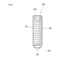
- FIG. 4 is a side view showing the configuration of the ball screw 220.
- the ball screw 220 includes a main body portion 221 and a ball body 225.
- the main body 221 is provided with a concave ball receiving portion 222 for accommodating the ball body 225 on the tip end side thereof, and the ball body 225 is housed in the ball receiving portion 222.
- the opening side of the ball receiving portion 222 is provided with a diameter slightly smaller than that of the ball body 225 to prevent the ball body 225 from falling off from the ball receiving portion 222.
- the ball body 225 is preferably a ceramic sphere made of ceramic as a material. When the ball body 225 is a metal ball such as steel, a part of the ball may be melted due to frictional heat or the like, but in the case of a ceramic ball, such a part may be melted. Because there is no such thing.
- an operation recess 223 for inserting a tool such as a hexagonal hole
- a male screw 224 is provided on the outer peripheral portion of the main body portion 221.
- the male screw 224 is screw-coupled to the screw hole 211 described above. This screw connection prevents the ball screw 220 from coming out of the screw hole 211. Further, by screwing the ball screw 220 into the screw hole 211, the ball body 225 comes into contact with the drum member 82.
- the ball screw 220 is preferably a type that does not have a built-in spring. However, as the ball screw 220, a type having a built-in spring may be used. In this case, it is preferable to firmly screw the ball screw 220 into the screw hole 211.
- the ball pin 230 is a member to be inserted into the above-mentioned insertion hole 210.
- a concave ball receiving portion 232 for accommodating the ball body 233 is provided on the tip end side thereof.
- the ball body 233 is housed in the ball receiving portion 232.
- the opening side of the ball receiving portion 232 is also provided with a diameter slightly smaller than that of the ball body 233 to prevent the ball body 233 from falling off from the ball receiving portion 232.
- the ball body 233 is also preferably a ceramic sphere made of ceramics, like the ball body 225 described above.
- the insertion hole 210 is not formed with a female screw, no male screw is formed on the outer peripheral surface of the main body portion 231.
- the ball screw 220 may be substituted as the ball pin 230.
- the male screw 224 existing in the ball screw 220 is in a state of being inserted into the insertion hole 210 without being screwed.
- the operation lever 240 is a tool for pushing the ball pin 230 toward the drum member 82 in a state where the ball pin 230 is inserted into the insertion hole 210 in order to press the drum member 82 with the ball pin 230.
- FIG. 6 is a plan view showing the configuration of the operating lever 240. As shown in FIG. 6, the operating lever 240 is provided with a handle portion 241 and a locking portion 242. The handle portion 241 is a portion to be gripped by the user and a portion to be pressed against the end surface (rear end portion) of the ball pin 230.
- the handle portion 241 is provided with a concave fitting portion 243 for fitting the end surface (rear end portion) of the ball pin 230.
- the configuration may be adopted.
- the fitting portion 243 is configured so as not to penetrate the handle portion 241 so that the ball pin 230 can be satisfactorily pushed by the handle portion 241.
- the fitting portion 243 also has a hole for fitting in such a tapered shape. The shape of the ball pin 230 prevents the ball pin 230 from coming off through the fitting portion 243.
- the locking portion 242 is a portion that is hooked (locked) in the recess 324a of the tubular portion 324 located around the central hole 323 of the motor cover 32.
- the locking portion 242 has a substantially semicircular shape, and the inner peripheral side of the semicircular locking portion 242 is locked in the recess 324a. ..
- the rear end side of the ball pin 230 is fitted to the fitting portion 243.
- the inner peripheral side of the locking portion 242, which is one end side of the operation lever 240 is used as a fulcrum, and the other end side of the operation lever 240 is pushed toward one side (X1 side) in the axial direction (X direction). Then, the ball pin 230 is pressed toward the drum member 82.
- the fan 100 is removed from the motor 10 with a brake. After that, the ball screw 220 is screwed into the screw hole 211 so that the tip end side (ball body 225) of the ball screw 220 comes into contact with the drum member 82 with a predetermined pressing force.
- the ball pin 230 is inserted into the insertion hole 210. After that, the locking portion 242 of the operating lever 240 is inserted into the recess 324a of the tubular portion 324, and one end side of the operating lever 240 is locked in the recess 324a. Further, the rear end side of the ball pin 230 is fitted to the fitting portion 243 of the handle portion 241.
- the other end side of the operating lever 240 is pushed toward one side in the axial direction (X direction) while adjusting the pushing force. Then, depending on the pushing force, the pushing pressure between the brake shoe 83 and the inner peripheral portion 322a of the outer wall portion 322 is loosened. Then, the braking force in the brake mechanism 90 is weakened, and the load locked to the hook of the chain or the like is lowered by that amount.
- the load can be lowered satisfactorily while preventing the load from dropping suddenly.
- the brake shoe 83 is attached to the outer peripheral portion 82a of the drum member 82, and the inner peripheral portion 322a of the outer wall portion 322 of the motor cover 32 is attached. Press the brake shoe 83 against. Further, a screw hole 211 formed in the cover bottom 321 of the motor cover 32 covering the drum member 82, an insertion hole 210 formed in the cover bottom 321 and a ball body 225 (first ball) rotatable on one end side.
- a ball screw 220 that is provided with a body) and is screwed into the screw hole 211 until the ball body 225 (first ball body) is in contact with the drum member 82, and a ball body 233 (second ball body) that is rotatable on one end side.
- a ball pin 230 is provided, and the ball pin 230 is inserted into the insertion hole 210 until the ball body 233 (second ball body) is in contact with the drum member 82, and the ball body 225 (first ball body) is a drum.
- the ball pin 230 is inserted into the insertion hole 210, and the ball body 233 (second ball body) pushes the drum member 82 into the operating lever 240. And.
- the screw hole 211 and the insertion hole 210 are separated from each other by 1/4 or more in the circumferential direction of the cover bottom portion 321.
- the brake release mechanism 200 includes the insertion hole 210 and the screw hole 211 formed in the drum member 82, the ball screw 220 screwed into the screw hole 211, the ball pin 230 to be inserted into the insertion hole 210, and the ball pin. Since it is composed of an operation lever 240 for pushing 230, it has a simple structure. In particular, since it is not necessary to permanently install a mechanism for releasing the brake as disclosed in Patent Document 2, it is possible to prevent the motor 10 with a brake from becoming large.
- the ball screw 220 is screwed into the screw hole 211 to bring the ball body 225 (first ball body) on one end side of the ball screw 220 into contact with the drum member 82.
- the ball pin 230 is inserted into the insertion hole 210, and the operation lever 240 is operated so that the ball body 233 (second ball body) pushes the drum member 82.
- the pushing force of the brake shoe 83 against the inner peripheral portion 322a can be adjusted. Therefore, it is possible to easily release the brake mechanism without depending on the amount of screwing of the set screw or the like.
- the brake mechanism when the brake mechanism is released by the amount of screwing such as a set screw, the load wound on the hoisting machine may suddenly drop when the amount of screwing is too large. .. Moreover, in order to stop the load that has fallen vigorously with the brake mechanism, it is necessary to rotate it again in the direction of pulling out the set screw, etc., but that operation takes a certain amount of time, and the fall occurs. There is a risk that it will not be in time to stop.
- the brake spring The spring force of 84 causes the brake shoe 83 to be pressed against the inner peripheral portion 322a again to generate a braking force. Therefore, it is possible to immediately stop the load from falling.
- the ball body 225 (first ball body) and the ball body 233 (second ball body) can be ceramic spheres made of ceramics.
- a part of the ball body 225 (first ball body) and the ball body 233 (second ball body) is melted by frictional heat or the like. Can be prevented.
- the operation lever 240 has a locking portion 242 that is locked to the recess 324a of the tubular portion 324 provided at the center in the radial direction of the cover bottom portion 321 and a locking portion 242.
- the handle portion 241 is provided continuously with the handle portion 241, and the handle portion 241 is provided with a fitting portion 243 that fits with the other end side of the ball pin 230.
- the ball pin 230 is satisfactorily directed toward the drum member 82 by utilizing this principle. Can be pushed in. Moreover, since the other end side of the ball pin 230 is fitted to the fitting portion 243, the ball pin is used by using the operation lever 240 while preventing the relative misalignment between the ball pin 230 and the operation lever 240. The 230 can be satisfactorily pushed toward the drum member 82.
- the fitting portion 243 is a portion recessed from the surface of the handle portion 241.
- the fitting portion 243 is not limited to the portion in which the handle portion 241 is recessed in a concave shape.
- the fitting portion 243 may be a portion that protrudes from the handle portion 241 in a convex shape. In this case, it is preferable that the end face of the ball pin 230 has a concave portion corresponding to the convex shape.
- the cross-sectional shape of the main body 231 of the ball pin 230 is not limited to the circular shape.
- it may have an elliptical shape.
- the planar shape of the insertion hole 210 is also elliptical, it is possible to prevent the ball pin 230 from rotating in the insertion hole 210 when the drum member 82 rotates. As a result, it is possible to prevent the influence of the rotation of the ball pin 230 on the operating lever 240 side.
- the operation lever 240 has a locking portion 242, and the locking portion 242 is a portion to be inserted into the recess 324a of the tubular portion 324.
- the operating lever 240 may use a different configuration.
- the operating lever 250 as shown in FIG. 7 may be used.
- the operating lever 250 has a handle portion 251 gripped by an operator, and has a bifurcated portion from the handle portion 251. In this bifurcated portion, a pushing portion 252 existing on the same straight line as the handle portion 251 (or being the same member as the handle portion 251) and an insertion portion to be inserted into the boundary portion between the cover bottom portion 321 and the outer wall portion 322. 253 and are provided.
- the operation lever 250 When such an operation lever 250 is used, when the insertion portion 253 is inserted into the boundary portion between the cover bottom portion 321 and the outer wall portion 322 and the handle portion 251 is lifted, the operation lever 250 is operated with the insertion portion as a fulcrum. Rotates. Then, the pushing portion 252 is pushed down toward the ball pin 230, and the ball pin 230 presses the drum member 82. Therefore, the operating lever 250 can be used to release the brake mechanism 90.
- the ball pin 230 can be provided with a spring (see FIG. 7). In this case, when the operating levers 240 and 250 are released, the ball pin 230 tends to return in the direction away from the drum member 82, and the load can be stopped even faster.
- the ball pin 230 is inserted into the insertion hole 210.
- the cover bottom 321 may have a plurality of screw holes 211 without forming the insertion holes 210.
- a ball pin 230 having a diameter smaller than that of the screw hole 211 may be inserted into any of the screw holes 211 to replace the insertion hole 210.
- a screw hole having a diameter different from that of the screw hole 211 may be formed in the cover bottom portion 321 and a ball pin 230 having a diameter smaller than that of the screw hole may be inserted into the screw hole.
Landscapes
- Engineering & Computer Science (AREA)
- General Engineering & Computer Science (AREA)
- Mechanical Engineering (AREA)
- Power Engineering (AREA)
- Braking Arrangements (AREA)
- Connection Of Motors, Electrical Generators, Mechanical Devices, And The Like (AREA)
Priority Applications (1)
| Application Number | Priority Date | Filing Date | Title |
|---|---|---|---|
| JP2021574524A JP7305806B2 (ja) | 2020-01-30 | 2020-12-17 | ブレーキ解放機構、ブレーキ付モータ及び巻上機 |
Applications Claiming Priority (2)
| Application Number | Priority Date | Filing Date | Title |
|---|---|---|---|
| JP2020-013936 | 2020-01-30 | ||
| JP2020013936 | 2020-01-30 |
Publications (1)
| Publication Number | Publication Date |
|---|---|
| WO2021153071A1 true WO2021153071A1 (ja) | 2021-08-05 |
Family
ID=77078065
Family Applications (1)
| Application Number | Title | Priority Date | Filing Date |
|---|---|---|---|
| PCT/JP2020/047138 Ceased WO2021153071A1 (ja) | 2020-01-30 | 2020-12-17 | ブレーキ解放機構、ブレーキ付モータ及び巻上機 |
Country Status (2)
| Country | Link |
|---|---|
| JP (1) | JP7305806B2 (https=) |
| WO (1) | WO2021153071A1 (https=) |
Citations (5)
| Publication number | Priority date | Publication date | Assignee | Title |
|---|---|---|---|---|
| JPS5297111A (en) * | 1976-02-12 | 1977-08-15 | Kito Kk | Winder brake disengaging mechanism |
| JPS5771191U (https=) * | 1980-10-17 | 1982-04-30 | ||
| JP3396016B2 (ja) * | 1996-10-11 | 2003-04-14 | 株式会社三協精機製作所 | ブレーキ付きモータ |
| JP2007209123A (ja) * | 2006-02-02 | 2007-08-16 | Mitsubishi Electric Corp | 無励磁作動形電磁ブレーキ付き回転電機 |
| CN103078443A (zh) * | 2011-10-26 | 2013-05-01 | 大连黄海起重电机有限责任公司 | 一种起重电机 |
-
2020
- 2020-12-17 WO PCT/JP2020/047138 patent/WO2021153071A1/ja not_active Ceased
- 2020-12-17 JP JP2021574524A patent/JP7305806B2/ja active Active
Patent Citations (5)
| Publication number | Priority date | Publication date | Assignee | Title |
|---|---|---|---|---|
| JPS5297111A (en) * | 1976-02-12 | 1977-08-15 | Kito Kk | Winder brake disengaging mechanism |
| JPS5771191U (https=) * | 1980-10-17 | 1982-04-30 | ||
| JP3396016B2 (ja) * | 1996-10-11 | 2003-04-14 | 株式会社三協精機製作所 | ブレーキ付きモータ |
| JP2007209123A (ja) * | 2006-02-02 | 2007-08-16 | Mitsubishi Electric Corp | 無励磁作動形電磁ブレーキ付き回転電機 |
| CN103078443A (zh) * | 2011-10-26 | 2013-05-01 | 大连黄海起重电机有限责任公司 | 一种起重电机 |
Also Published As
| Publication number | Publication date |
|---|---|
| JPWO2021153071A1 (https=) | 2021-08-05 |
| JP7305806B2 (ja) | 2023-07-10 |
Similar Documents
| Publication | Publication Date | Title |
|---|---|---|
| EP2058268B1 (en) | Braking device with planar frictional surfaces for electric winch and electric winch | |
| US5582277A (en) | Caliper disk brake for steel mill cranes | |
| US7857289B2 (en) | Tapered braking device for electric winches | |
| JP2011529553A (ja) | ディスクブレーキ用の調整装置 | |
| US6488133B1 (en) | Clutch system and method | |
| WO2021153071A1 (ja) | ブレーキ解放機構、ブレーキ付モータ及び巻上機 | |
| CN1646824B (zh) | 电磁鼓式制动器 | |
| US3795290A (en) | Drum, rim grip braking device | |
| US6047805A (en) | Electric clutch and brake | |
| CN101607660B (zh) | 电梯用卷扬机 | |
| JP7257140B2 (ja) | ブレーキシリンダ及びユニットブレーキ | |
| JP4084350B2 (ja) | 手動運転安全機構付きウィンチ | |
| JP2005113965A (ja) | 電磁制動装置 | |
| JPH066294Y2 (ja) | 電磁ブレ−キ | |
| JP6710328B2 (ja) | エレベータ用巻上機 | |
| US20050242333A1 (en) | Automatic brake mechanism | |
| JP4408239B2 (ja) | 電磁ディスクブレーキ及びそれを備えたエレベーター用巻上機 | |
| JP7199116B1 (ja) | ブレーキ解放装置 | |
| JP2008100809A (ja) | エレベータのディスクブレーキ | |
| JP4779767B2 (ja) | 制動装置 | |
| JP4455891B2 (ja) | 巻上機のブレーキ装置 | |
| JP2564716Y2 (ja) | 竪型電磁ブレーキ・クラッチの摩耗低減装置 | |
| JP2002130341A (ja) | 無励磁作動形電磁ブレーキの手動解放装置 | |
| JPH061870U (ja) | 無励磁作動形電磁ブレーキ | |
| JPH04347018A (ja) | 電磁ディスクブレーキの制動力解放手段 |
Legal Events
| Date | Code | Title | Description |
|---|---|---|---|
| 121 | Ep: the epo has been informed by wipo that ep was designated in this application |
Ref document number: 20916962 Country of ref document: EP Kind code of ref document: A1 |
|
| ENP | Entry into the national phase |
Ref document number: 2021574524 Country of ref document: JP Kind code of ref document: A |
|
| NENP | Non-entry into the national phase |
Ref country code: DE |
|
| 122 | Ep: pct application non-entry in european phase |
Ref document number: 20916962 Country of ref document: EP Kind code of ref document: A1 |