WO2021152960A1 - 表示方法 - Google Patents
表示方法 Download PDFInfo
- Publication number
- WO2021152960A1 WO2021152960A1 PCT/JP2020/042589 JP2020042589W WO2021152960A1 WO 2021152960 A1 WO2021152960 A1 WO 2021152960A1 JP 2020042589 W JP2020042589 W JP 2020042589W WO 2021152960 A1 WO2021152960 A1 WO 2021152960A1
- Authority
- WO
- WIPO (PCT)
- Prior art keywords
- area
- image
- display
- setting
- recording
- Prior art date
- Legal status (The legal status is an assumption and is not a legal conclusion. Google has not performed a legal analysis and makes no representation as to the accuracy of the status listed.)
- Ceased
Links
Images












Classifications
-
- H—ELECTRICITY
- H04—ELECTRIC COMMUNICATION TECHNIQUE
- H04N—PICTORIAL COMMUNICATION, e.g. TELEVISION
- H04N5/00—Details of television systems
- H04N5/76—Television signal recording
- H04N5/91—Television signal processing therefor
-
- H—ELECTRICITY
- H04—ELECTRIC COMMUNICATION TECHNIQUE
- H04N—PICTORIAL COMMUNICATION, e.g. TELEVISION
- H04N23/00—Cameras or camera modules comprising electronic image sensors; Control thereof
- H04N23/60—Control of cameras or camera modules
- H04N23/62—Control of parameters via user interfaces
-
- G—PHYSICS
- G03—PHOTOGRAPHY; CINEMATOGRAPHY; ANALOGOUS TECHNIQUES USING WAVES OTHER THAN OPTICAL WAVES; ELECTROGRAPHY; HOLOGRAPHY
- G03B—APPARATUS OR ARRANGEMENTS FOR TAKING PHOTOGRAPHS OR FOR PROJECTING OR VIEWING THEM; APPARATUS OR ARRANGEMENTS EMPLOYING ANALOGOUS TECHNIQUES USING WAVES OTHER THAN OPTICAL WAVES; ACCESSORIES THEREFOR
- G03B15/00—Special procedures for taking photographs; Apparatus therefor
-
- G—PHYSICS
- G03—PHOTOGRAPHY; CINEMATOGRAPHY; ANALOGOUS TECHNIQUES USING WAVES OTHER THAN OPTICAL WAVES; ELECTROGRAPHY; HOLOGRAPHY
- G03B—APPARATUS OR ARRANGEMENTS FOR TAKING PHOTOGRAPHS OR FOR PROJECTING OR VIEWING THEM; APPARATUS OR ARRANGEMENTS EMPLOYING ANALOGOUS TECHNIQUES USING WAVES OTHER THAN OPTICAL WAVES; ACCESSORIES THEREFOR
- G03B17/00—Details of cameras or camera bodies; Accessories therefor
- G03B17/18—Signals indicating condition of a camera member or suitability of light
-
- G—PHYSICS
- G03—PHOTOGRAPHY; CINEMATOGRAPHY; ANALOGOUS TECHNIQUES USING WAVES OTHER THAN OPTICAL WAVES; ELECTROGRAPHY; HOLOGRAPHY
- G03B—APPARATUS OR ARRANGEMENTS FOR TAKING PHOTOGRAPHS OR FOR PROJECTING OR VIEWING THEM; APPARATUS OR ARRANGEMENTS EMPLOYING ANALOGOUS TECHNIQUES USING WAVES OTHER THAN OPTICAL WAVES; ACCESSORIES THEREFOR
- G03B5/00—Adjustment of optical system relative to image or object surface other than for focusing
-
- H—ELECTRICITY
- H04—ELECTRIC COMMUNICATION TECHNIQUE
- H04N—PICTORIAL COMMUNICATION, e.g. TELEVISION
- H04N23/00—Cameras or camera modules comprising electronic image sensors; Control thereof
- H04N23/60—Control of cameras or camera modules
- H04N23/63—Control of cameras or camera modules by using electronic viewfinders
- H04N23/631—Graphical user interfaces [GUI] specially adapted for controlling image capture or setting capture parameters
-
- H—ELECTRICITY
- H04—ELECTRIC COMMUNICATION TECHNIQUE
- H04N—PICTORIAL COMMUNICATION, e.g. TELEVISION
- H04N23/00—Cameras or camera modules comprising electronic image sensors; Control thereof
- H04N23/60—Control of cameras or camera modules
- H04N23/63—Control of cameras or camera modules by using electronic viewfinders
- H04N23/633—Control of cameras or camera modules by using electronic viewfinders for displaying additional information relating to control or operation of the camera
- H04N23/635—Region indicators; Field of view indicators
-
- H—ELECTRICITY
- H04—ELECTRIC COMMUNICATION TECHNIQUE
- H04N—PICTORIAL COMMUNICATION, e.g. TELEVISION
- H04N5/00—Details of television systems
- H04N5/76—Television signal recording
-
- H—ELECTRICITY
- H04—ELECTRIC COMMUNICATION TECHNIQUE
- H04N—PICTORIAL COMMUNICATION, e.g. TELEVISION
- H04N5/00—Details of television systems
- H04N5/76—Television signal recording
- H04N5/765—Interface circuits between an apparatus for recording and another apparatus
- H04N5/77—Interface circuits between an apparatus for recording and another apparatus between a recording apparatus and a television camera
- H04N5/772—Interface circuits between an apparatus for recording and another apparatus between a recording apparatus and a television camera the recording apparatus and the television camera being placed in the same enclosure
Definitions
- One embodiment of the present invention relates to a method of displaying an image.
- a technique for cutting out and storing an image of one of a plurality of subjects in the image from an image taken by one photographing device has already been developed.
- the technique described in Patent Document 1 can be mentioned.
- a plurality of different video regions are set in the shooting range of the shooting device, and the video in one of the video regions is recorded.
- the area of the image to be recorded can be changed (switched) among a plurality of areas. Thereby, for example, it is possible to obtain a zoomed-in image for each of a plurality of subjects in the photographed image while the photographing device is fixed.
- One embodiment of the present invention has been made in view of the above circumstances, and improves convenience for the user in a method of displaying an image in which a part of the captured image can be cut out and the cut-out image can be switched.
- the purpose is to make it.
- one embodiment of the present invention is a display method for displaying an image captured by a photographing device, and a plurality of setting areas are included in a reference area which is an imaging area of a reference image.
- the selection process for selecting the recording area which is the area of the recorded video to be recorded from a plurality of setting areas, and the selection process, and the recording area for being re-recorded from the plurality of setting areas is a display method including a switching step of selecting and switching a recording area, and a display step of displaying a recorded image, a reference image, and a sign indicating each position of a plurality of setting areas in the reference image.
- the sign includes the boundary of the setting area, and in the display process, the image within the boundary may be highlighted among the reference images.
- the sign may be displayed in a state where the setting areas do not overlap each other.
- the sign indicating the position of the recording area in the reference image and the sign indicating the position of the standby area which is a setting area other than the recording area may be displayed in different modes from each other.
- a sign indicating the position of the moving area which is a setting area that moves following the moving subject, may be displayed in a form different from the sign indicating the position of the setting area other than the moving area.
- the recorded image and the reference image may be displayed on different displays.
- the display step includes a first display step of displaying a recorded image, a reference image and a sign, and a second display step of displaying the recorded image and not displaying the reference image and the sign, and the first display.
- a first display step of displaying a recorded image, a reference image and a sign and a second display step of displaying the recorded image and not displaying the reference image and the sign, and the first display.
- One of the steps and the second display step specified by the user may be carried out.
- the recorded image and the standby image which is the image of the setting area other than the recording area may be displayed on different displays.
- the number of signs displayed in the display process may be variable, and in the display process, the identification information of the signs may be displayed for each sign. In that case, when the number of displayed signs is changed, it is preferable that the identification information set for each sign is maintained before and after the change in the number of displayed signs.
- one embodiment of the present invention is a display method for displaying an image captured by a photographing device, which comprises a setting step of setting a plurality of setting areas in a reference area which is an imaging area of a reference image.
- the recording area which is the area of the recorded video to be recorded, is selected from a plurality of setting areas, and after the selection process is performed, the recording area is reselected from the plurality of setting areas to switch the recording area.
- a switching process a determination process for determining priority for a plurality of standby areas when a setting area other than the recording area is set as a standby area, and a display for displaying a plurality of standby images which are images of a plurality of standby areas.
- the display process is based on the priority among the plurality of standby areas.
- This is a display method for displaying the standby video in the standby region selected in the above-mentioned manner, or displaying a plurality of standby videos in a size according to the priority.
- a subject in a plurality of standby images may be detected, and the priority of each of the plurality of standby areas may be determined according to the information regarding the detected subject.
- the achievement in which the standby area is selected as the recording area in the past may be specified, and the priority of each of the plurality of standby areas may be determined based on the information regarding the specified achievement.
- one embodiment of the present invention is a display method for displaying an image captured by a photographing device, which comprises a setting step of setting a plurality of setting areas in a reference area which is a photographing area of a reference image.
- the recording area which is the area of the recorded video to be recorded, is selected from a plurality of setting areas, and after the selection process is performed, the recording area is reselected from the plurality of setting areas to switch the recording area.
- control process may include at least one of a process for suppressing the change of the reference area, a process for urging the change of the reference area, and a process for notifying the proposal information regarding the change of the reference area. good.
- the control process related to zooming by the optical device may be executed in the control step.
- the reference area is determined when the user's recording start instruction is received, and the control process may be a process related to the change of the reference area after the time when the recording start instruction is received.
- one embodiment of the present invention is a display method for displaying an image captured by a photographing device, which comprises a setting step of setting a plurality of setting areas in a reference area which is an imaging area of a reference image.
- the recording area which is the area of the recorded video to be recorded, is selected from a plurality of setting areas, and after the selection process is performed, the recording area is reselected from the plurality of setting areas to switch the recording area.
- a switching process and a display process for displaying a set image which is an image of a setting area are provided, and at least one of the number of displayed set images and the display size of the set image displayed in the display process is a recorded image. It is a display method determined according to at least one item of resolution and aspect ratio.
- the number of displayed set images displayed in the display process may be determined according to at least one item adjusted according to the recording format of the recorded image.
- the present embodiment relates to a method of displaying an image using the photographing apparatus 10 shown in FIGS. 1 to 3.
- the embodiments described below are merely examples for facilitating the understanding of the present invention, and do not limit the present invention. That is, the present invention may be modified or improved from the embodiments described below as long as it does not deviate from the gist thereof. Further, the present invention includes an equivalent thereof.
- the photographing device 10 is, for example, a digital camera that photographs an image.
- the “video” means a live video (live view image), that is, a video shot in real time, unless otherwise specified.
- the moving image in the present embodiment is mainly a moving image. That is, the photographing device 10 photographs a moving image at a predetermined frame rate.
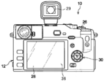
- the photographing device 10 is, for example, an interchangeable lens model, and includes a photographing device main body 12 and a photographing lens 14 as shown in FIGS. 1 and 2.
- the photographing lens 14 is interchangeably attached to the mount 13 of the photographing apparatus main body 12.
- the present invention is not limited to this, and the photographing device 10 may be a model with an integrated lens.
- the photographing lens 14 includes an optical unit 17, an aperture 20, a zoom drive unit 21, a focus drive unit 22, and an aperture drive unit 23.
- the optical unit 17 includes an optical device 18 for zooming (for example, a zoom lens).
- zooming for example, a zoom lens
- the photographing device 10 of the present embodiment includes an optical zoom function and an electronic zoom (digital zoom) function for enlarging a subject in an image by electronic processing.
- the optical unit 17 includes an optical device 19 for focusing (for example, a focus lens).
- an optical device 19 for focusing for example, a focus lens
- the focus drive unit 22 operates to move the optical device 19.
- the focusing position is automatically adjusted so as to focus on a predetermined portion in the image.
- the optical unit 17 includes a wide-angle lens, an ultra-wide-angle lens, a 360-degree lens, an anamorphic lens, and the like.
- the photographing device 10 can photograph an image with a wide angle of view in the lateral direction (horizontal width direction) of the photographing device 10.
- the angle of view of the photographing device 10 changes with the execution of the optical zoom and the like.
- the maximum angle of view (total angle of view) of the photographing device 10 is determined according to the design specifications of the optical unit 17 and the image sensor 40 described later.
- the optical unit 17 provided in the photographing device 10 is not limited to one, and a plurality of optical units 17 having different angles of view may be provided.
- the diaphragm 20 has a variable opening shape, and the aperture shape is adjusted by the diaphragm drive unit 23. By adjusting the aperture shape, the amount of aperture for the incident light on the photographing lens 14 changes and the amount of exposure is adjusted.
- the photographing apparatus main body 12 includes an operation unit including an operation button 30. Further, a release button 26, which is one of the operation units, is arranged on the upper surface of the photographing apparatus main body 12. When the release button 26 is pressed, recording of the image taken by the photographing device 10 or the image cut out from the image (strictly speaking, the recorded image described later) is started.
- the photographing area of the photographing device 10 that is, the range within the angle of view of the photographing device 10, is determined when the user's recording start instruction is received. Further, the photographing area changes according to, for example, turning on / off of electronic image stabilization. When the electronic image stabilization is turned off at the time of accepting the recording start instruction, the shooting area is generally a full-size (full angle of view) shooting area.
- the user's operation related to the video recording start instruction is not limited to pressing the release button 26, and may be an operation of touching a predetermined position on the rear display 28 described later.
- the image captured by the photographing device 10 at the angle of view at that time will be referred to as a "reference image”. Further, the shooting area of the reference image is referred to as a "reference area”.
- a display shown in FIG. 2 (hereinafter, also referred to as a rear display 28) is provided on the back surface of the photographing device main body 12.
- the display 28 on the back is composed of, for example, an LCD (Liquid Crystal Display), an organic EL (Organic Electroluminescence) display, an LED (Light Emitting Diode) display, electronic paper, or the like.
- LCD Liquid Crystal Display
- organic EL Organic Electroluminescence
- LED Light Emitting Diode
- the display 28 on the back displays a reference image, a recorded image described later, and the like.
- the photographing device 10 having a display has a video display function, it will be used as a video display device.
- the display 28 on the back can display information other than video, and displays, for example, advice or proposal information regarding shooting (see FIG. 18).
- the photographing apparatus main body 12 of the present embodiment includes an electronic viewfinder (denoted as EVF in FIG. 3) 29 as a sub-display.
- EVF electronic viewfinder
- the same image can be displayed on the rear display 28 and the electronic viewfinder 29, or different images can be displayed on each other.
- the photographing apparatus does not have to include the electronic viewfinder 29. Further, it is not necessary to display the image on the electronic viewfinder 29 and not to display the image on the display 28 on the rear surface.
- a touch panel 36 for detecting a user operation is provided inside the display 28 on the back surface or on the exposed surface of the display 28. For example, when the user touches a predetermined position on the display 28 on the back surface, the touch panel 36 detects the touch position and outputs the detection result to the control unit 46 described later.
- the photographing apparatus main body 12 is further provided with a shutter 38, an image sensor 40, an analog signal processing circuit 44, a control unit 46, an internal memory 50, a card slot 52, and a buffer memory 56.
- the image sensor 40 is an image sensor, receives light that has passed through the photographing lens 14, converts the received image into an electric signal (video signal), and outputs the light.
- a solid-state image sensor such as a CCD (Charged Coupled Device) or a CMOS (Complementary Metal Oxide Semiconductor Image Sensor) can be used.
- the control unit 46 controls each unit of the photographing device 10 and executes various processes related to image capture, display, recording, and the like.
- the control unit 46 includes a controller 47 and a video processing unit 48 as shown in FIG.
- the control unit 46 has one or a plurality of processors, and the control unit 46 is configured by the cooperation of the processors and the control program.
- the processor is, for example, a CPU (Central Processing Unit), an FPGA (Field Programmable Gate Array), a DSP (Digital Signal Processor), an ASIC (Application Specific Integrated Circuit), a GPU (Graphics Processing Unit), or another IC (Integrated Circuit). It may be composed of. Alternatively, a processor may be configured by combining these. Further, as represented by SoC (System on Chip) or the like, the processor may configure the functions of the entire control unit 46 including the controller 47 and the video processing unit 48 with one IC (Integrated Circuit) chip.
- SoC System on Chip
- the processor may configure the functions of the entire control unit 46 including the controller 47 and the video processing unit 48 with one IC (Integrated Circuit) chip.
- the hardware configuration of each processor described above may be realized by an electric circuit (Circuitry) in which circuit elements such as semiconductor elements are combined.
- the controller 47 controls each part of the photographing device 10 based on a user operation or according to a predetermined control program. For example, the controller 47 controls the image sensor 40 and the analog signal processing circuit 44 so as to capture an image at a predetermined frame rate.
- the controller 47 controls each drive unit 21 to 23, an image sensor 40, an analog signal processing circuit 44, and the like so that the shooting conditions become desired conditions.
- the shooting conditions include focus, exposure amount, white balance, and the like. That is, the controller 47 realizes the autofocus (AF) function, the autoexposure (AE) function, and the auto white balance (AWB) function, which are the automatic adjustment functions of the photographing device 10.
- controller 47 controls the video processing unit 48 so as to start recording the video when the user receives the recording start instruction.
- the video processing unit 48 converts the analog video signal sent from the analog signal processing circuit 44 into digital video data, and performs gamma correction, white balance correction, and the like on the digital video data.
- the processed digital video data is compressed in a compression format conforming to a predetermined standard.
- the video processing unit 48 generates compressed digital image data at a predetermined frame rate during shooting, and acquires a video (strictly speaking, a frame image) from the data.
- the image acquired at this time corresponds to the reference image captured in the reference area.
- the video processing unit 48 cuts out the recorded video from the reference video under the control of the controller 47.
- the recorded image is an image having an angle of view smaller than the angle of view of the reference image, and is an image of a part of the reference area.
- the recorded video is generated at the same frame rate as the reference video and is displayed on, for example, the rear display 28 or the electronic viewfinder 29.
- the recorded video is recorded on a recording medium.
- a video file of the recorded video is created.
- the resolution (number of pixels) and aspect ratio of the recorded video are determined according to the recording format (moving image format) of the recorded video.
- the recording format is not particularly limited and can be freely determined.
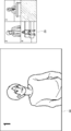
- the image processing unit 48 extracts an extracted image whose size is slightly smaller than that of the uncorrected image taken at all angles of view while the electronic image stabilization is enabled (ON). Is extracted. Then, when the extracted image is displaced due to vibration or the like, the image processing unit 48 executes electronic image stabilization and shifts the position of the extracted region in the image before correction (for example, shifts from the position of the solid line to the position of the broken line in FIG. 4). .. While the electronic image stabilization is on, the extracted video serves as the reference video.
- the internal memory 50 built in the photographing apparatus main body 12 and the memory card 54 that can be attached to and detached from the card slot 52 are recording media, and for example, a recorded image is recorded.
- the internal memory 50 and the memory card 54 may be provided in a device (external) different from the photographing apparatus main body 12. In that case, the control unit 46 may record the recorded video on an external recording medium by wire or wirelessly.
- the buffer memory 56 functions as a work memory of the control unit 46.
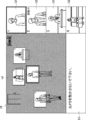
- the photographing device 10 records a recorded image cut out from the reference image on a recording medium. Further, the photographing device 10 can switch (switch) the recorded image by changing the cutout area in the reference image. Such a function will be described with reference to FIG. Note that in FIG. 5, for convenience of explanation, the illustration of the subject in the video is omitted.
- the reference image is displayed on the display (for example, the display 28 on the back).
- the image of the entire angle of view is the reference image
- the area surrounded by the outermost edge in FIG. 5 is the reference area As.
- the extracted video extracted from the video at all angles of view serves as the reference video
- the region surrounded by the broken line frame in FIG. 5 serves as the reference region At.
- the control unit 46 sets the setting area Ar in the reference areas As and At.
- the setting area Ar is a part of the reference areas As and At.
- the subject in the reference image is reflected in the setting area Ar (see FIG. 6).
- the position and size of the setting area Ar can be adjusted automatically or based on the user operation.
- the user can change the position and size of the setting area Ar on which the subject is projected, for example, according to the position and size of the subject in the reference image by performing a predetermined operation or the like on the screen.
- the aspect ratio of the setting area Ar is determined to be a value according to the recording format (moving image format) of the recorded video. Therefore, when changing the size of the setting area Ar, the size is changed while the aspect ratio of the setting area Ar remains constant.
- the aspect ratio of the setting area Ar may be determined without depending on the recording format of the recorded video, and in that case, the size of the setting area Ar may be changed while changing the aspect ratio.
- the sign f is displayed in the reference image displayed on the display at that time.
- the sign f indicates the position of the set area Ar in the reference image, and includes the boundary of the set area Ar.
- the boundary of the setting area Ar is set to distinguish (distinguish) the setting area Ar from its surroundings.
- Examples of the marker f including the boundary include a frame surrounding the setting area Ar and a graphic object such as a pointer indicating a representative position of the setting area Ar.
- differences in brightness, chromaticity, shading, etc. between the set area Ar and its surroundings also correspond to the marker f.
- the setting area Ar and its surroundings can be distinguished, it can be included in the category of the marker f.
- a sign f composed of a colored rectangular frame will be described as an example.
- a plurality of setting areas Ar can be set in the reference image.
- the sign f is displayed for each setting area Ar.
- the identification information (the number displayed on the upper right of the sign f in FIG. 5) is displayed for each sign f.
- the identification information is information that is individually assigned to each sign f by the control unit 46 according to a predetermined assignment rule. By displaying the identification information together with the sign f, the user can distinguish each sign f.
- the identification information is not particularly limited, and may be a number, a character, or a symbol, or may be a display color of the sign f divided for each sign f. When the number is used as the identification information, it is desirable that the number is a serial number.
- the user selects the recording area Ap, which is the area of the recorded video, from the plurality of set setting areas Ar.
- the control unit 46 selects the recording area Ap from the plurality of setting areas Ar according to the user selection operation. As a result, the setting area Ar in which the video in the area is recorded, that is, the recording area Ap is determined.
- the control unit 46 When the recording area Ap is determined, the control unit 46 indicates the positions of the sign f indicating the position of the recording area Ap and the positions of the other set areas Ar among the signs f for each set area Ar displayed in the reference image.
- the label f is displayed in a manner different from each other.
- the display mode of the sign f includes the color, brightness, density (shading degree), shape, edge line thickness and line type of the sign f, and the presence / absence of blinking display. In the case shown in FIG. 5, the display color and thickness of the sign f indicating the position of the recording area Ap are different from those of the other signs f.
- the recording of the video in the recording area Ap (hereinafter referred to as the recorded video) is started.
- the reference region that is, the orientation and angle of view of the photographing apparatus 10.
- the reference area is determined once means that the reference area is determined once when the recording start instruction is received. Further, even after the reference area is determined, the user can freely change the reference area. Incidentally, when the user changes the reference area, it is preferable to change the position of the set area according to the position of the subject, as will be described later.
- a zoom image of a portion of interest in the reference image can be recorded.
- the recorded image is an image having an angle of view smaller than the angle of view of the reference image, but if the reference image has a high image quality (for example, if the number of pixels is 10 million or more), the image has a sufficiently high image quality. It becomes.
- the number of pixels of the reference image is not particularly limited, but the lower limit thereof is preferably 10 million or more, and more preferably 60 million or more. Further, the upper limit of the number of pixels is preferably 1 billion or less, and more preferably 500 million or less. When the number of pixels is larger than the above lower limit, the visibility of the recorded image is guaranteed. Further, when the number of pixels is smaller than the above upper limit, the amount of data of the reference video is reduced, and the processing speed by the control unit 46 can be increased.
- the recording area Ap after selecting one setting area Ar determined as the recording area Ap from the plurality of setting areas Ar, the recording area Ap can be switched to another setting area Ar during video recording. As a result, the video of the recording area Ap before switching and the video of the recording area Ap after switching can be recorded respectively. This will be described in detail with reference to FIG.
- the photographing device 10 photographs a plurality of subjects (people) in a certain scene (place) and sets a setting area Ar for each subject as shown in FIG.
- one setting area Ar selected by the user from the plurality of setting areas Ar becomes the recording area Ap.
- four setting areas Ar are set, and the setting area Ar surrounded by the sign f of the identification information “1” is the recording area Ap.
- the image of the setting area Ar which is the recording area Ap at that time is recorded.
- the recording area Ap is reselected.
- the recorded video is switched.
- the recorded video can be switched by reselecting the recording area Ap during the video recording.
- the control unit 46 When the recorded video is switched, the control unit 46 records the recorded video before the switching and the recorded video after the switching, and combines these videos into one moving image. As a result, as shown in FIG. 7, a moving image file (video file) in which the subject in the video changes as the recorded video is switched is acquired.
- video file video file
- the present invention is not limited to this, and the recorded video before switching and the recorded video after switching may be recorded as separate file data without being combined. Further, the reference video and the standby area described later may also be recorded as separate file data.
- a sign f indicating a position in the reference image is displayed for each of the plurality of setting areas Ar including the recording area Ap.
- the display method of the present embodiment has improved convenience (ease of use) from the viewpoint of making it easier to grasp the position of the setting area Ar.
- Such an effect is particularly effective in a configuration in which the recording area Ap can be switched in the plurality of setting areas Ar. That is, by displaying the sign f for each setting area Ar, it is possible to easily grasp which image in the reference image the recorded image after switching is.
- the number of setting areas Ar (setting number) is automatically changed according to the change or based on the user operation. Can be done. For example, as shown in FIG. 8, when a new subject enters the reference image, a new setting area Ar can be added at the position of the subject. On the contrary, when the subject in the reference image moves to the outside of the reference image, the setting area Ar which is the image area of the subject can be automatically deleted.
- the setting area Ar is made to follow the movement of the subject. Can be displaced.
- the tracking of the subject can be realized by a known subject detection technique by video analysis.
- the setting area Ar for tracking the moving subject is the recording area Ap, the image of the moving subject can be recorded.
- the moving area Am is not limited to the area that moves following the moving subject, and may be an area that moves at a constant speed or an irregular speed in a predetermined direction.
- Video display flow The processing flow (hereinafter, video display flow) executed by the control unit 46 of the photographing device 10 will be described with reference to FIG.
- the image display flow is started.
- the user makes an initial adjustment of the photographing device 10.
- the resolution (number of pixels) and aspect ratio of the recorded video are adjusted by designating the recording method.
- Such adjustment is performed, for example, when the photographing device 10 is started for the first time, and the adjustment contents are retained thereafter.
- the above adjustment may be performed by the device manufacturer before the photographing device 10 is shipped.
- the user can readjust these values after starting the photographing device 10 in order to review the resolution, aspect ratio, and the like once adjusted.
- the control unit 46 first starts the shooting process (S001).
- This shooting step is a step of shooting a reference image in the reference region at that time. It is preferable that the real-time reference image is displayed as a live view image on the display 28 or the like on the back surface with the start of shooting. The shooting process is continued until the user instructs the end of shooting or the power of the shooting device 10 is turned off.
- the setting step is a step of automatically setting a plurality of setting areas Ar in the shooting area of the reference image.
- the setting process the initial position and initial size of each setting area Ar are set, and then the position and size of each setting area Ar are automatically changed based on the user operation or according to a predetermined rule. It is possible.
- the selection step is a step of selecting the recording area Ap from the plurality of setting areas Ar set in the setting step based on the user's selection operation.
- the control unit 46 may display each image of the plurality of setting areas Ar (hereinafter, referred to as “setting image”) on the display. In this case, the user can check the setting video for each of the plurality of setting areas Ar.
- the recording step is a step of recording a recorded image, which is an image of the selected recording area Ap, on a recording medium.
- the recorded video is recorded according to a predetermined recording format (moving image format). Further, as described above, the reference area is determined at the time of receiving the recording start instruction that triggers the start of the recording process.
- the control unit 46 executes the display process (S006).
- the display step is a step of displaying a plurality of set images including a recorded image, a reference image at that time, and a sign f in the reference image on a display. The user can see these images, confirm the position of each setting area Ar in the reference image, and grasp which setting area Ar is the recording area Ap.
- control unit 46 executes the control process (S007).
- the control step is a step of executing the control process relating to the change of the reference region determined at the time of receiving the recording start instruction.
- the control process includes a process for suppressing a change in the reference region, and is, for example, a control process related to zoom (optical zoom) by the optical device 19.
- the switching step is a step of switching the recording area Ap by reselecting the recording area Ap from the plurality of setting areas Ar according to the reselection instruction by the user after performing the selection step.
- the switching step is carried out, in the subsequent recording step, the video (recorded video) of the recording area after the switching is recorded.
- the control unit 46 reads out the position information of the setting area Ar stored in advance in the photographing device 10. Then, the setting area Ar is automatically set at the position indicated by the read position information. At this time, for the purpose of making the sign f easier for the user to see, it is more preferable to highlight the image in the sign f in the reference image. For example, in the reference image, the brightness other than the image in the sign f (that is, in the boundary of the setting area Ar) may be lowered or grayed out (see FIG. 18) may be displayed.
- the second UI screen 102 is displayed on the rear display 28 as shown in FIG.
- the user selects one of a plurality of recording patterns prepared in advance, and presses a button indicating the selected pattern among the buttons Bt3, Bt4, and Bt5 on the second UI screen 102.
- the recording pattern for example, a "previously used pattern", a "preset pattern”, and a "user input pattern” can be selected.
- the control unit 46 automatically sets the setting area Ar at a predetermined position in the reference image based on the reference image being photographed.
- the third UI screen 103 is displayed as shown in FIG. The user selects one of a plurality of automatic setting patterns prepared in advance, and presses a button indicating the selected pattern among the buttons Bt6, Bt7, and Bt8 on the third UI screen 103.
- the automatic setting pattern for example, a "scene recognition pattern”, a "subject detection pattern”, and an "AF position identification pattern" can be selected.
- the sign f it is preferable to display the sign f in a state where the setting regions Ar do not overlap each other and do not overlap each other at the start of the setting process. This makes it easier to identify the plurality of markers f, and makes it easier to set the setting area Ar in the setting step.
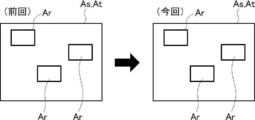
- the control unit 46 reads out the position information of the setting area Ar set in the setting process in the previous (immediately before) video display flow.
- This position information indicates the position of each of the plurality of setting areas Ar set in the setting step of the previous video display flow, and is stored in, for example, the internal memory 50 of the photographing device 10. It is preferable that the stored position information is retained even after the power of the photographing apparatus 10 is turned off.
- the size information of the setting area Ar may be stored together with the position information of the setting area Ar. In that case, when the previously used pattern is selected, the position information and the size information may be read together.
- the control unit 46 automatically sets the setting area Ar at the position indicated by the read position information, that is, at the same position as the setting position in the previous video display flow.
- Such a previously used pattern is effective when shooting an image with the same composition as the previous image display flow (for example, when shooting an image at the same place and at the same angle).
- the read position information indicates the position of the setting area Ar set in the previous (immediately before) video display flow, but the present invention is not limited to this.
- the position information of the setting area Ar set in the setting steps for several times performed in the past may be stored respectively. In that case, it is preferable to set the current setting area Ar at the position of the setting area Ar set in the setting process of the times specified by the user in the stored position information.
- the control unit 46 reads out the position information of the setting area Ar arranged in the predetermined fixed arrangement pattern.
- the standard arrangement pattern is pre-registered in the photographing apparatus 10, or is newly registered when the program is updated after purchase.
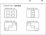
- the fourth UI screen 104 shown in FIG. 13 is displayed on the rear display 28.
- a plurality of types of patterns are displayed on the fourth UI screen 104 so as to be selectable, and the user selects one of the preset patterns.
- the control unit 46 automatically sets the setting area Ar at a position corresponding to the preset pattern selected by the user.
- Such a preset pattern is effective when there is a pattern corresponding to the composition when shooting an image with a predetermined composition (for example, when shooting an image at a specific place).
- the number of types of preset patterns, the number of setting areas Ar in each preset pattern, and the arrangement position are not particularly limited and can be arbitrarily determined.
- the control unit 46 reads out the position information of the setting area Ar determined based on the user's operation.
- the user's operation here is an input operation for registering the position of the setting area Ar, and is performed in a stage prior to the setting process (for example, a stage of initial registration regarding the pattern).
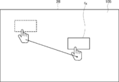
- the above input operation is performed, for example, through the input screen 105 for pattern registration shown in FIG.
- the user touches and drags the inner area of the area setting indicator fx displayed on the input screen 105.
- the display position of the marker fx after dragging is registered as the position of the setting area Ar.
- the control unit 46 automatically sets the setting area Ar at the position indicated by the read position information, that is, the setting position determined based on the input operation of the user.
- a user input pattern is effective when a pattern is prepared based on the user's input in a situation where the above-mentioned preset pattern cannot be used.
- the size of the setting area Ar may also be registered. That is, information indicating the position and size of the setting area Ar determined based on the input operation of the user may be stored. In that case, each of the plurality of setting areas Ar will be set at the position and size registered as the user input pattern.
- the control unit 46 recognizes the shooting scene of the reference image based on the reference image.
- the shooting scene of the reference image is, for example, a landscape, an event, a type of subject, a scene (for example, a daytime view or a night view), a situation (for example, weather, etc.), etc., which are shot as a reference image. be.
- a known scene recognition technique can be used as a method for recognizing a shooting scene based on a reference image. For example, a method of determining whether or not the brightness or tint of an image in a predetermined region is within a preset range can be mentioned. Further, machine learning may be performed using the correct answer label indicating the shooting scene of the video and the video data as a learning data set, and the shooting scene of the reference video may be recognized by the scene recognition model obtained as a result of the learning. ..
- the control unit 46 detects the subject in the reference image and automatically sets the setting area Ar at the position of the detected subject.
- the subject in the reference image is a subject other than the landscape in the reference image, which can be detected by the control unit 46, and includes, for example, a person, an animal, a vehicle, and the like.
- a known template matching technique may be applied.
- the image of the subject may be stored in advance as a template image, the template image may be collated with each portion in the reference image, and an image similar to the template image may be detected as the subject.
- a model for recognizing a subject in an image may be constructed by machine learning, and the model may be used to detect a subject in a reference image.
- a known algorithm such as YOLO (You Only Look Once) or R-CNN (Region with Convolution Neural Network) can be used.
- control unit 46 can set one setting area Ar for each of the detected subjects. At this time, the entire corresponding subject may be accommodated in each setting area Ar, or a part of the corresponding subject (for example, the upper body portion including the face) may be accommodated. ..
- the setting area Ar can be automatically set for the subject in the reference image without the user's trouble.
- the subject detection pattern is effective when recording the image of the subject in the reference image.
- the control unit 46 identifies a position in the reference image in which the feature for determining the focus of the photographing device 10 satisfies the reference, and the setting area Ar is set at the specified position. Is set automatically.
- the feature for determining the focus is, for example, a feature for determining the in-focus position in the reference image.
- the autofocus is a phase difference AF (Auto Focus) method
- the phase difference corresponds to the above characteristics.
- the autofocus is a contrast AF method
- the contrast between a plurality of pixels corresponds to the above-mentioned feature.
- the AF method may be an AF method using directional light, or an AF method using DFD (Depth from defocus).
- the position that satisfies the reference is the position where the above-mentioned features (for example, phase difference or contrast) are the features at the time of focusing.
- the control unit 46 identifies a focused position by the AF function as a position satisfying the reference in the reference image. Then, as shown in FIG. 15, the setting area Ar is automatically set for the specified position (the focused position and the hatched position in FIG. 15). At this time, for example, the size of the setting area Ar may be automatically set according to the area of the focused portion in the reference image.
- the image of the part that is in focus by the AF function is often recorded. Based on this point, by setting the setting area Ar at the in-focus position, it is possible to easily record the in-focus image, which improves convenience for the user.
- another setting area Ar is automatically set accordingly.
- another setting area Ar is set at a symmetrical position (for example, a position symmetrical with respect to the center of the reference image) at the focused position.
- a plurality of setting areas Ar can be automatically set in the reference area.
- the position where another setting area Ar is set is not limited to the above position.
- the entire reference area when the entire reference image is in focus in the AF position specifying pattern, the entire reference area may be set as one setting area Ar. Further, when the subject is not detected in the reference image and an appropriate setting position of the setting area Ar cannot be found in the reference image, the setting area Ar may be set near the center of the reference image.
- the in-focus position in the reference image is taken as an example of the shooting conditions, and the feature for determining the in-focus position in the reference image is set to a position satisfying the reference (that is, a focused position). It was decided to set the area Ar.
- the shooting conditions may be other than the in-focus position, and examples thereof include an exposure amount and a white balance.
- the shutter speed and ISO sensitivity are excluded from the shooting conditions referred to here.
- the setting area Ar is set at a position in the reference image where the feature for determining the exposure amount (for example, the pixel value or the brightness) satisfies the reference. Can be done.
- the setting area Ar may be set at a position where the exposure amount is adjusted to an appropriate value by the AE (Automatic Exposure) function.
- the setting area Ar may be set at a position where the exposure amount is relatively low and a position where the exposure amount is relatively high in the reference image.
- the setting area Ar can be set at a position in the reference image where the feature for determining the white balance (for example, chromaticity) satisfies the reference.
- the setting area Ar may be set at a position where the white balance is adjusted to an appropriate value by the AWB (Auto White Balance) function.
- AWB Auto White Balance
- the user selects an arbitrary pattern from the plurality of arrangement patterns explained above.
- the setting area Ar is set reflecting the intention or preference of the user.
- the setting area Ar is automatically set, so that the user does not have to take time (setting work). That is, the display method of the present embodiment has improved convenience (ease of use) from the viewpoint of saving the user's trouble and setting the setting area Ar in the reference area by reflecting the user's intention and the like. It is a thing.
- the arrangement pattern may be an arrangement pattern in which a plurality of arrangement patterns shown in FIG. 11 are combined. For example, a scene recognition pattern and an AF position specifying pattern may be adopted at the same time to set a plurality of setting areas Ar.
- the above-mentioned pattern is merely an example, and an arrangement pattern other than the above-mentioned pattern may be added, and conversely, some of the above-mentioned patterns may be omitted.
- the candidate Ac of the setting region is automatically set at the position of the feature portion in the reference region. Is set. Then, when the user performs a predetermined operation on the set candidate Ac, the setting area Ar is set at the position of the set candidate Ac.
- the procedure for setting the candidate Ac in the setting process will be described.
- the control unit 46 determines whether or not a feature portion exists in the reference video based on the characteristics (for example, pixel values) of each pixel of the reference video.
- the featured part is a part where a visual change occurs in the reference image (excluding the part detected as a subject), for example, a part where there is movement in the background image, a color, a brightness, and the like.
- the illuminations appearing in the upper left portion of the figure correspond to the featured portion.
- the control unit 46 carries out the first setting step.
- the first setting step is a step of automatically setting the candidate Ac of the setting area at the position of the featured portion in the reference image.
- a sign indicating the position of the candidate Ac in the reference image (hereinafter, referred to as a candidate sign K) is displayed.
- the candidate sign K is displayed in a mode different from that of the sign f indicating the position of the setting area Ar.
- the candidate marker K in FIG. 16 is a substantially L-shaped graphic object representing a square in a rectangular area surrounding a feature portion.
- the type and shape of the candidate sign K are not particularly limited, and may be, for example, a pointer in the shape of an arrow or a finger, or a graphic object consisting of a symbol such as a circle or a star.
- the shade difference (difference in brightness) between the candidate Ac in the reference image and its surroundings may be used as the candidate marker K.
- the second setting step is a step in which the control unit 46 sets the setting area Ar at the setting position of the candidate Ac in which the operation is performed according to the operation (for example, tap operation) for the candidate Ac of the user.
- the operation for example, tap operation
- the candidate Ac of the setting area can be automatically set for the feature portion in the reference image that is not recognized as a subject but has a visual change. Further, by displaying the candidate sign K indicating the position of the set candidate Ac in the reference video, the user can easily confirm the candidate Ac. Further, when the user performs a predetermined operation on the candidate Ac, the setting area Ar is set at the position of the candidate Ac. As a result, the setting area Ar can be set for the feature portion that the user is interested in in the reference video. Furthermore, if the setting area Ar thus set is selected as the recording area, it is possible to record the image of the featured portion.
- the display step is a step of displaying a recorded image, a reference image, and a sign f indicating each position of a plurality of setting areas Ar in the reference image on a display.
- the sign f is displayed for each set area Ar in the reference image.
- each image of the setting area Ar other than the recording area Ap (hereinafter, referred to as a standby image) can be displayed.
- the candidate sign K indicating the position of the feature points is displayed together with the sign f in the reference image.
- the recorded image, the reference image, and the standby image can be simultaneously displayed on the screen of the rear display 28 (hereinafter referred to as a display screen).
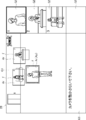
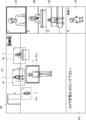
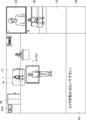
- a display screen For example, as shown in FIG. 18, the display screen is divided into a main screen G1, a sub screen G2, and an information display screen G3.
- the standby video can be displayed on the sub screen G2.
- the main screen G1 occupies a relatively wide range (for example, more than half of the display screen) on the display screen and displays a reference image.
- the aspect ratio of the main screen G1 is preferably set to the same value as the aspect ratio of the reference image.
- the sub screen G2 is a screen smaller than the main screen G1 and is arranged in a row along the vertical direction or the horizontal direction of the display screen.
- Each sub screen G2 displays a recorded video or one standby video. It is preferable that the aspect ratio of each sub screen G2 is set to the same value as each aspect ratio of the recorded video and the standby video.
- the information display screen G3 is a screen for displaying character information other than video, and for example, as shown in FIG. 18, advice regarding video recording is displayed.
- the layout of the display screen (for example, the size and arrangement position of each of the main screen G1 and the sub screen G2) is not limited to the form shown in FIG. 18, and can be freely arranged according to the specifications of the device or the preference of the user. Can be designed.
- a sign f is displayed for each of the plurality of setting areas Ar set in the setting step together with the reference image.
- the number of signs f (display number) displayed on the main screen G1 in the display process is variable, and the maximum number of signs f that can be displayed (display upper limit number) can be displayed at the same time.
- the sign f indicating the position of the recording area Ap and the sign f indicating the position of the other setting area Ar are displayed in different modes from each other.
- the sign f indicating the position of the recording area Ap is preferably highlighted.
- the border color may be a relatively conspicuous color such as red or fluorescent color, the border may be thicker, or the border may be thicker. It is good to blink it.
- the image (that is, the recorded image) itself in the recording area Ap may be highlighted.
- the moving area Am set for the subject moves following the subject.
- the sign f indicating the position of the moving area Am is displayed in a manner different from the sign f indicating the position of the setting area Ar other than the moving area Am.
- the control unit 46 uses the electronic zoom function to change the size of the moving area Am according to the change in the subject ratio, and adjusts so that the subject ratio is kept constant.
- the moving area Am may move to the vicinity of the edge of the reference area (that is, the outer edge of the angle of view), or may extend beyond the reference area.
- the control unit 46 displays a warning message on the information display screen G3 or outputs a warning sound to notify the user of the above situation.
- the control unit 46 calculates the amount of deviation of the reference image by the electronic image stabilization, and adjusts the position of each setting area Ar based on the calculated amount of deviation. As a result, the position of each setting area Ar with respect to the reference area is maintained before and after the electronic image stabilization is performed. It is preferable that the function of adjusting the position of the setting area Ar along with the electronic image stabilization can be freely switched on and off according to the user's operation.
- the identification information of the sign f is displayed for each sign f.
- the identification information of each sign f is fixed during the display step, and even if the number of signs f displayed changes during the display step, it is maintained unchanged before and after that. For example, in FIG. 18, when the display of the sign f whose identification number is “3” is stopped, the identification numbers of the other signs f (that is, “1”, “2”, “4”) do not change. ..
- By fixing the identification number of each sign f during the execution of the display step in this way it is possible to easily grasp which setting area Ar exists where even if the number of signs f displayed changes, for example.
- a plurality of setting images including a recorded image and a standby image are displayed on the plurality of sub screens G2. Specifically, one corresponding setting image is displayed on each of the plurality of sub screens G2.
- the aspect ratio of each sub-screen G2 is the same as the aspect ratio of the corresponding set image, the set image can be displayed well on the screen.
- the recorded image is preferably highlighted.
- the color of the screen frame, the thickness or line type of the frame line, the presence or absence of lighting, etc. are different between the sub screen G2 on which the recorded image is displayed and the sub screen G2 on which other setting images are displayed. It is preferable to do so. As a result, the user who sees a plurality of set images on the display can easily distinguish which image is the recorded image.
- a plurality of execution modes of the display process are prepared, and the image display method in the display process changes for each mode. That is, the display process is performed according to the mode specified by the user. For example, when the user specifies the first mode, the first display process is performed as the display process. In the first display step, as shown in FIG. 18, the reference image and the sign f for each setting area Ar are displayed on the main screen G1, and the recorded image and the standby image are displayed on the sub screen G2. On the other hand, when the user specifies the second mode, the second display process is performed as the display process. In the second display step, as shown in FIG. 19, the recorded image and the standby image are displayed, and the reference image and the sign f for each setting area Ar are not displayed.
- the recorded image, the standby image, the reference image, and the sign f for each setting area Ar do not necessarily have to be displayed on the same display (for example, the display 28 on the back surface). That is, as shown in FIG. 20, the image displayed on the main screen G1 and the image displayed on the sub screen G2 may be displayed on different displays. To give a specific example, the image displayed on the main screen G1 is displayed on the rear display 28, and the image displayed on the sub screen G2 is displayed on the electronic viewfinder 29 or an external monitor (not shown) connected to the photographing device 10. You may.
- the display process includes the first display process and the second display process, and one of these two display processes specified by the user is carried out.
- the displayed image can be switched according to the needs of the user.
- the first display step may be performed to display the reference image and the sign f.
- the second display step it is preferable to carry out the second display step to display only the recorded video and the standby video.
- the execution mode of the display process that is, which of the first display process and the second display process is to be executed, can be freely switched according to the switching operation by the user during the execution of the display process.
- the user can switch which display process is adopted through the touch panel 36 or the operation button 30 shown in FIG.
- the recorded image and other set images may be displayed on the same display.
- the recorded video may be displayed on the main screen G1 in the display screen, and the standby video may be displayed on the sub screen G2.
- the recorded video and other set video may be displayed on different displays.
- the recorded image may be displayed on the rear display 28, and other set images may be displayed on the electronic viewfinder 29 or an external monitor (not shown) connected to the photographing device 10.
- the proposal information described later is displayed on the information display screen G3, for example, the proposal information described later is displayed.
- the information display screen G3 can display advice for shooting, a warning message, and the like for the user. For example, if it is necessary to adjust the exposure amount, ISO sensitivity, or the like during the recording process, that fact may be displayed. Further, information other than the above can be displayed on the information display screen G3. For example, the current values regarding the shooting mode, resolution, ISO sensitivity, and other shooting conditions currently adopted, and the on / off of various functions such as electronic zoom may be displayed.
- the number of sub-screens G2 is determined according to at least one item (hereinafter, simply referred to as "at least one item") of the resolution and aspect ratio of the recorded video. That is, the number of set images displayed on the sub screen G2 is determined according to at least one item. Similarly, the size of each sub screen G2 is also determined according to at least one item. That is, the display size of the set image is the size corresponding to at least one item.
- the display number (strictly speaking, the maximum display number) and the display size of the set video in the display process are the number and size according to the recording format of the recorded video.
- the number of set images to be displayed and the display size are determined according to at least one item, so that each of the plurality of set images including the recorded image can be displayed satisfactorily.
- each set image can be displayed well on the sub screen G2 at an appropriate resolution.
- the aspect ratio of the recorded video is determined according to the recording format of the recorded video, but the aspect ratio of the recorded video may be arbitrarily set without depending on the recording format. In that case, as the aspect ratio of the recorded video is adjusted, the number and size of the sub screens G2 are changed according to the adjusted aspect ratio.
- both the display number and the display size (that is, the number and size of the sub screen G2) of the set video displayed in the display process are determined according to at least one item.
- the present invention is not limited to this, and either the number of displayed images or the display size of the set video may be determined according to at least one item.
- the number of displayed images set in the display process does not have to be determined according to at least one item.
- the user may set or change the number of displays.
- the number of displayed images set in the display process is determined according to the resolution and aspect ratio of the recorded image as described above.
- one of the displayed setting images is a recorded image, and the rest is a standby image. Therefore, the set value regarding the display number of the standby video, that is, the maximum display number is determined according to the resolution and the aspect ratio of the recorded video, and is specifically one less than the number of the sub screen G2. In the case shown in FIG. 21, the maximum number of standby images displayed is three.
- the number of setting areas Ar in the reference area changes according to the subject or the like in the reference image, and the number of setting areas Ar other than the recording area Ap, that is, the number of a plurality of standby areas changes accordingly.
- the number of standby areas is six.
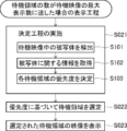
- the control unit 46 carries out the display process according to the flow shown in FIG. Explaining the flow of the display process shown in FIG. 22, the control unit 46 executes the determination process when the number of the plurality of standby areas reaches the maximum number of display of the standby image (S021).
- the control unit 46 determines the priority for each of the plurality of standby areas.
- the control unit 46 detects a subject in the standby image for each of the plurality of standby images (S101).
- the control unit 46 acquires information about the subject in the detected standby video (S102).
- the control unit 46 may acquire the actual information as the recording area, which will be described later, instead of the information about the subject in the standby video.
- Examples of the information about the subject include the time or number of times the subject is shown in the reference image during the shooting period, and the size (display size) of the subject in the reference image. This information can be acquired by the control unit 46 analyzing, measuring, or counting the reference image during the shooting period.
- the face of the person may be recognized by a technique such as pattern matching, the importance of the person whose face is recognized may be specified, and the specific result may be used as information about the subject.
- the importance of a person for example, the attributes of the person whose face is recognized (for example, family, relatives, acquaintances or others) can be determined, and the importance can be obtained from the determination result.
- the priority may be determined according to the subject category (for example, person, animal, object, landscape, etc.). Further, the priority may be determined by giving priority to the subject whose detection timing is earlier. As for the information about the subject, of course, other than the above can be considered. It is desirable that the user can freely select what kind of information is used as information about the subject in the determination process.
- the subject category for example, person, animal, object, landscape, etc.
- the priority may be determined by giving priority to the subject whose detection timing is earlier.
- the information about the subject of course, other than the above can be considered. It is desirable that the user can freely select what kind of information is used as information about the subject in the determination process.
- control unit 46 determines the priority of each of the plurality of standby areas according to the information regarding the detected subject (S103).
- the control unit 46 selects N standby areas from the plurality of standby areas based on the priority (S022).
- the number N of the standby areas selected is the maximum number of standby images to be displayed, and is a number determined according to the number of sub screens G2 (for example, a number that is one less than the number of sub screens G2).
- the control unit 46 selects N standby areas in order from the one with the highest priority.
- the control unit 46 displays the images (standby images) of the selected N standby areas on the sub screen G2 (S023).
- the sub-screens G2 are arranged in the vertical direction of the display screen as shown in FIG. 21, it is desirable to display the standby image in the standby area having a higher priority on the higher sub-screen G2.
- N standby images selected according to the priority are displayed. As a result, it is possible to appropriately display the standby video having a high priority while complying with the restrictions on the screen display.
- the method of determining the priority is not limited to the method of determining the priority based on the information about the subject in the standby image.
- the priority may be determined according to the actual information as the recording area. More specifically, for each of the plurality of standby areas, the number of times the recording area is selected from the start of shooting to the present time, the time of the recording area, or the time when the recording area is selected immediately before. Specify the elapsed time, etc. These pieces of information correspond to information about the achievements selected as the recording area in the past. Then, the priority of each of the plurality of standby areas may be determined based on the above-mentioned information on the actual results. For example, when the information on the actual results is the number of times or time selected as the recording area, the higher the number of times or time, the higher the priority may be given.
- N standby areas are selected based on the priority, and only the video of the selected standby areas is displayed, but the present invention is not limited to this.
- the upper N standby areas and the lower standby areas may be selected in descending order of priority.
- the standby images of the upper N standby areas may be displayed first, and the standby images of the lower standby areas may be displayed by scrolling or switching the display screen as shown in FIG. 23. ..
- each of the plurality of standby images may be displayed in a size according to the priority. For example, as shown in FIG. 24, the standby image in the standby area having a high priority is displayed on the sub screen G2 of the normal size, and the standby image in the standby area having a low priority is displayed on the sub screen G2x of the reduced size. You may. In this way, each of the plurality of standby images can be displayed, and the standby area having a high priority can be displayed more easily.
- the control step is a step of executing a control process for suppressing a change in the reference region, and is performed at least after the reference region is determined. That is, the control process is a process for suppressing a change in the reference area after the time when the user's recording start instruction is received.
- the control unit 46 locks the zoom drive unit 21 to stop the movement of the zoom optical device 18.
- the optical zoom function is limited during the recording process, the reference region is fixed, and the angle of view at that time is maintained.
- the control process executed to suppress the change of the reference area is not limited to the above process, and may be, for example, a process for notifying the proposal information regarding the change of the reference area.
- a message prohibiting optical zoom may be displayed on the information display screen G3, or may be reproduced by voice or the like.
- a message prohibiting the operation of moving the photographing device 10 for example, a panning operation
- a message recommending fixing the photographing device 10 using a pan head such as a tripod is displayed. You may.
- control step may be carried out before the determination of the reference region (that is, before the reception of the recording start instruction), or may be carried out, for example, during the setting step. In this case, it is possible to prevent the reference area from changing while a plurality of setting areas Ar are set in the reference area.
- the change step is a step of executing a change process relating to a change in the number of displayed images of the set area Ar (that is, the set image).
- the control unit 46 executes the change process.
- the change step is a step of executing a change process relating to a change in the number of displayed images of the set area Ar (that is, the set image).
- the number of displayed images can be dynamically increased or decreased during the recording process.
- control unit 46 monitors the reference image and determines whether or not the number of subjects in the reference image has increased (S031). When the number of subjects in the reference image increases, the control unit 46 executes a change step (S032). In such a change process, a change process for increasing the number of displayed set images is executed.
- the setting area Ar is added according to the increase of the subjects in the reference image, and the setting image of the added setting area Ar is newly displayed on the display.
- the number of displayed set images increases. For example, as shown in FIGS. 26 and 27, when the number of subjects in the reference image increases from 3 to 4, the number of displayed images (that is, the number of images displayed on the sub screen G2) starts from 3. Increase to four.
- the number of signs f in the reference image displayed on the main screen G1 is linked to the number of the added setting area Ar. It increases by the amount (see FIG. 27).
- the setting area Ar is set at the position of a new subject in the reference image, but the present invention is not limited to this.
- the candidate Ac of the setting area may be set instead of the setting area Ar.
- a sign indicating the position of the candidate Ac (specifically, the above-mentioned candidate sign K) is displayed in the reference video.
- the setting area Ar is added to the position of the candidate Ac by using this as a trigger.
- the set image of the added setting area Ar is newly displayed, and the number of displayed setting images increases.
- the proposal information regarding the addition of the setting area Ar may be output. ..
- a message proposing to add a setting area Ar to a new subject position to increase the number of displayed set images may be displayed on the information display screen G3, or may be reproduced by voice or the like. In this way, as the change process, a process of outputting proposal information regarding the change of the display number of the set video may be executed.
- the control unit 46 monitors the reference image during the execution of the recording process, and determines whether the moving area Am in the reference area overlaps with another setting area Ar (S033). Then, when the moving area Am overlaps with another setting area Ar as shown in FIG. 28, or when it is just before overlapping, the control unit 46 outputs a warning message or a warning sound (S034). This is because, in a situation where the moving area Am overlaps with the other setting area Ar, the subject in one area may not appear behind the subject in the other area.
- the control unit 46 executes the change process (S036). In such a change process, a change process for reducing the number of displayed set images is executed.
- step S036 the overlapping moving area Am and the other setting area Ar are updated to one setting area Ar, and the updated setting image of the setting area Ar is displayed on the display.
- the image of the moving area Am and the image of the other setting area Ar displayed separately as shown in FIG. 28 are integrated into one image including the subject of each of these two images as shown in FIG. 29. NS.
- the number of set areas Ar is reduced by one, and the number of displayed set images is also reduced by one.
- the size and position of the updated setting area Ar are set so that the subjects of the above two images can be accommodated.
- the identification information of the sign f indicating the set area Ar after the update may be inherited from the identification information of the sign f indicating one of the two areas before the update (that is, the moving area Am and the other set area Ar). good.
- a new identification number may be assigned to the updated setting area Ar.
- the control unit 46 periodically determines whether or not each of the plurality of setting areas Ar satisfies the stop condition during the execution of the recording process (S037).
- the cancellation condition is a standard for determining whether or not to stop displaying the image (setting image) of the setting area Ar, and examples thereof include the following conditions (1) to (3).
- Cancellation condition (1) At least a part of the set area Ar is out of the reference area due to optical zoom or the like.
- Cancellation condition (2) There is no change in the set image of the setting area Ar for a certain period of time, or there is no subject in the set image.
- Cancellation condition (3) The setting area Ar has not been selected as the recording area for a certain period of time or longer.
- the discontinuation condition is not limited to the above conditions (1) to (3), and conditions other than the above may be included in the discontinuation condition.
- the control unit 46 executes the change step (S038). In such a change process, a change process for reducing the number of displayed set images is executed.
- step S0308 the display of the set image of the setting area Ar that satisfies the stop condition is stopped.
- the display of the setting image of the setting area Ar is stopped as shown in FIG. 30 (sub). It disappears from the screen G2).
- the number of displayed set images is reduced by one.
- the setting area Ar hereinafter referred to as a stop area
- the display of the sign f indicating the position of the stop area is also stopped on the main screen G1 as shown in FIG. ..
- the proposal information regarding the stop of the display of the set image may be output.
- a message recommending that the display of the set image of the setting area Ar that satisfies the cancellation condition be stopped may be displayed on the information display screen G3, or may be reproduced by voice or the like.
- another image an image different from the set image
- the stopped area is stored in the internal memory 50 or the like in the photographing device 10 while the recording process is performed.
- the period in which the stop area is stored may be until the end of shooting or until the power of the shooting device 10 is turned off.
- an operation icon such as the return button Bt9 is displayed on the main screen G1.
- the user can give a redisplay instruction for the set image of the stop area by, for example, tapping the return button Bt9.
- the control unit 46 executes the change process (S040). In such a change step, a change process for redisplaying the stored set image of the stop area is executed based on the user's redisplay instruction.
- the image of the canceled area is displayed on the sub screen G2 again, and the number of displayed set images returns to the number before the display of the set image of the stopped area is stopped.
- the set image of the stop area that can be redisplayed is not limited to the image of the immediately preceding stop area (the setting area in which the display of the set image was stopped most recently). For example, it may be possible to redisplay the images of the canceled areas for the past several times during the current shooting period. In that case, the stop area for the past several times is stored in the photographing device 10, and the user specifies which stop area the set image is to be redisplayed and instructs the user to redisplay the image.
- the control unit 46 monitors the reference image during the execution of the recording process, and determines whether the number of subjects in the reference area exceeds the upper limit of the number of the set area Ar (S041). .. Then, when the number of subjects exceeds the upper limit of the number of set areas Ar, the control unit 46 executes the changing step (S042). In such a change process, a change process relating to a decrease in the number of displayed set images is executed. In the change process in step S042, a message recommending that the number of subjects exceeds the upper limit of the number of set areas Ar and that the number of displayed images to be reduced is reduced is displayed on the information display screen G3, or voice or the like. Play with.
- the user reviews the setting of the setting area Ar with this as an opportunity, and deletes unnecessary setting area Ar such as the setting area Ar that is not selected as the recording area for the longest period. As a result, the number of displayed set images is reduced by the number of set areas Ar deleted by the user.
- the series of steps S031 to S042 described above are repeatedly performed during the execution of the recording process, and end at the end of the recording process (S043).
- the change process is carried out with the change in the reference image (for example, addition of a subject, etc.) and the establishment of the cancellation condition as an opportunity, and the number of displayed images is changed as appropriate.
- the user can easily confirm the number of set images according to the situation at that time, and can omit the confirmation of the images such as the set area Ar which is unlikely to be the recording area.
- convenience for the user is improved.
- the photographing device 10 displays various images as a display device, but the present invention is not limited to this.
- the display device may be configured by a photographing device 10, a camera controller connected to the photographing device 10 by wire or wirelessly, an external external display, or the like.
- the camera controller takes on the function of the control unit 46, causes the photographing device 10 to capture a reference image, and causes the external display to display various images.
- the camera controller may set the setting area Ar, select and reselect (switch) the recording area, record the recorded image, and the like.
- the present invention is not limited to this, and as a control process relating to the change of the reference area, a process for prompting the change of the reference area may be executed.
- the reference region can be adjusted according to changes in the reference image (for example, movement of the subject in the reference image).
- the recorded image is zoomed up by electronic zoom in the recording process.
- the zoom magnification exceeds a predetermined value, the resolution of the recorded image becomes a certain value or less, and there is a possibility that it becomes difficult to obtain the desired image quality.
- information prompting the change of the reference region may be displayed on the information display screen G3 by performing optical zoom instead of electronic zoom.
- the control unit 46 may move the zoom drive unit to forcibly perform optical zoom so that the resolution becomes equal to or higher than a predetermined value, and the reference region may be automatically changed.
- the relative position of each setting region Ar with respect to the reference region changes.
- control unit 46 calculates the amount of change in the reference region and adjusts the position and size of each setting area Ar based on the calculated amount of change. As a result, the relative position of each setting area Ar with respect to the reference area is maintained before and after the zooming is performed.
- the moving region Am may follow the movement of the subject to reach the vicinity of the edge of the reference region, or at least a part of the moving region may protrude from the reference region.
- information prompting the moving of the photographing device 10 that is, changing the reference image
- a known detection sensor such as a gyro sensor provided in the photographing device 10 moves the photographing device 10 (for example, the amount of displacement). Should be detected.
- each setting area Ar it is preferable to adjust the position and size of each setting area Ar based on the movement of the photographing device 10 detected by the control unit 46. As a result, the relative position of each setting area Ar with respect to the reference area is adjusted according to the changed reference area. At this time, the setting area Ar that goes out of the reference area due to the change of the reference area may be automatically deleted.
- the recorded video is a moving image, that is, a set of a plurality of frame images continuously shot at a constant frame rate.
- the recorded video is not limited to a moving image and may be a still image.
- the control unit 46 displays the reference image as a live view image on the main screen G1 and sets a plurality of setting areas Ar in the reference area. The user selects the recording area Ap from the plurality of setting areas Ar, and the control unit 46 displays the plurality of setting images including the recorded image on the sub screen G2. Then, when the user gives a recording instruction by operating the release button 26 or the like, the control unit 46 may record the recorded image as a still image on the recording medium.
- the setting area Ar when a subject in the reference image is detected, the setting area Ar is automatically set at the position of the detected subject.
- the case is not limited to the case where the setting area Ar is immediately set at the position of the detected subject, and the candidate Ac of the setting area may be set first at the position of the detected subject.
- the candidate sign K may be displayed at the position of the candidate Ac, and when the user performs a predetermined operation on the candidate sign K, the setting area Ar may be set at the position of the candidate Ac.
- the display of the setting image is stopped, while the setting area Ar is stored in the photographing device 10 during the recording process.
- the present invention is not limited to this, and the setting area Ar that satisfies the cancellation condition may be deleted, and the video in that area may not be stored.
- a screen (not shown) for selecting whether to delete the setting area Ar is displayed separately, and after confirming the user's intention regarding the necessity of deletion, the setting area Ar that satisfies the cancellation condition is deleted. It is good to do.
- the photographing device is a digital camera, but it may be a mobile terminal such as a video camera, a mobile phone with an imaging optical system, a smartphone, or a tablet terminal.
- the image pickup lens may be a lens unit externally attached to the image pickup optical system of the mobile terminal.
Landscapes
- Engineering & Computer Science (AREA)
- Multimedia (AREA)
- Signal Processing (AREA)
- Human Computer Interaction (AREA)
- Physics & Mathematics (AREA)
- General Physics & Mathematics (AREA)
- Studio Devices (AREA)
- Indication In Cameras, And Counting Of Exposures (AREA)
Priority Applications (6)
| Application Number | Priority Date | Filing Date | Title |
|---|---|---|---|
| JP2021574472A JP7513639B2 (ja) | 2020-01-30 | 2020-11-16 | 表示方法 |
| CN202080094541.9A CN115004681B (zh) | 2020-01-30 | 2020-11-16 | 显示方法 |
| US17/871,990 US12335595B2 (en) | 2020-01-30 | 2022-07-25 | Display method |
| JP2024072468A JP7675894B2 (ja) | 2020-01-30 | 2024-04-26 | 表示方法 |
| JP2025073513A JP2025105828A (ja) | 2020-01-30 | 2025-04-25 | 表示方法 |
| US19/206,067 US20250274563A1 (en) | 2020-01-30 | 2025-05-13 | Display method |
Applications Claiming Priority (2)
| Application Number | Priority Date | Filing Date | Title |
|---|---|---|---|
| JP2020-013155 | 2020-01-30 | ||
| JP2020013155 | 2020-01-30 |
Related Child Applications (1)
| Application Number | Title | Priority Date | Filing Date |
|---|---|---|---|
| US17/871,990 Continuation US12335595B2 (en) | 2020-01-30 | 2022-07-25 | Display method |
Publications (1)
| Publication Number | Publication Date |
|---|---|
| WO2021152960A1 true WO2021152960A1 (ja) | 2021-08-05 |
Family
ID=77078235
Family Applications (1)
| Application Number | Title | Priority Date | Filing Date |
|---|---|---|---|
| PCT/JP2020/042589 Ceased WO2021152960A1 (ja) | 2020-01-30 | 2020-11-16 | 表示方法 |
Country Status (4)
| Country | Link |
|---|---|
| US (2) | US12335595B2 (https=) |
| JP (3) | JP7513639B2 (https=) |
| CN (1) | CN115004681B (https=) |
| WO (1) | WO2021152960A1 (https=) |
Cited By (1)
| Publication number | Priority date | Publication date | Assignee | Title |
|---|---|---|---|---|
| JP2023091490A (ja) * | 2021-12-20 | 2023-06-30 | キヤノン株式会社 | 情報処理装置、情報処理装置の制御方法及びプログラム |
Families Citing this family (1)
| Publication number | Priority date | Publication date | Assignee | Title |
|---|---|---|---|---|
| JP2024164694A (ja) * | 2023-05-15 | 2024-11-27 | キヤノン株式会社 | 映像出力装置及び方法、プログラム及び記憶媒体 |
Citations (4)
| Publication number | Priority date | Publication date | Assignee | Title |
|---|---|---|---|---|
| JP2005175683A (ja) * | 2003-12-09 | 2005-06-30 | Nikon Corp | デジタルカメラ |
| JP2011175508A (ja) * | 2010-02-25 | 2011-09-08 | Mazda Motor Corp | 駐車支援システム |
| JP2014042357A (ja) * | 2008-09-12 | 2014-03-06 | Sanyo Electric Co Ltd | 撮像装置および画像処理装置 |
| JP2016201756A (ja) * | 2015-04-14 | 2016-12-01 | ソニー株式会社 | 画像処理装置、画像処理方法、および画像処理システム |
Family Cites Families (9)
| Publication number | Priority date | Publication date | Assignee | Title |
|---|---|---|---|---|
| US7551200B2 (en) | 2005-01-25 | 2009-06-23 | Panasonic Corporation | Camera controller and zoom ratio control method for the camera controller |
| US8525892B2 (en) | 2005-04-21 | 2013-09-03 | Canon Kabushiki Kaisha | Imaging apparatus and control method therefor |
| JP5312256B2 (ja) * | 2008-09-12 | 2013-10-09 | 三洋電機株式会社 | 撮像装置および撮像システム |
| JP2014089304A (ja) * | 2012-10-30 | 2014-05-15 | Xacti Corp | 視点計測装置及び電子機器 |
| JP6256298B2 (ja) | 2014-10-30 | 2018-01-10 | キヤノンマーケティングジャパン株式会社 | 撮像装置、その制御方法とプログラム |
| KR102644782B1 (ko) * | 2016-07-25 | 2024-03-07 | 한화비전 주식회사 | 모니터링 장치 및 시스템 |
| KR20260027320A (ko) | 2016-10-04 | 2026-02-27 | 주식회사 비원영상기술연구소 | 영상 데이터 부호화/복호화 방법 및 장치 |
| CN107295252B (zh) * | 2017-06-16 | 2020-06-05 | Oppo广东移动通信有限公司 | 对焦区域显示方法、装置及终端设备 |
| KR102668233B1 (ko) * | 2018-09-04 | 2024-05-23 | 삼성전자주식회사 | 관심 영역을 통해 움직이는 외부 객체에 대해 프레임 레이트를 제어하여 이미지들을 획득하는 전자 장치 및 그의 동작 방법 |
-
2020
- 2020-11-16 JP JP2021574472A patent/JP7513639B2/ja active Active
- 2020-11-16 CN CN202080094541.9A patent/CN115004681B/zh active Active
- 2020-11-16 WO PCT/JP2020/042589 patent/WO2021152960A1/ja not_active Ceased
-
2022
- 2022-07-25 US US17/871,990 patent/US12335595B2/en active Active
-
2024
- 2024-04-26 JP JP2024072468A patent/JP7675894B2/ja active Active
-
2025
- 2025-04-25 JP JP2025073513A patent/JP2025105828A/ja active Pending
- 2025-05-13 US US19/206,067 patent/US20250274563A1/en active Pending
Patent Citations (4)
| Publication number | Priority date | Publication date | Assignee | Title |
|---|---|---|---|---|
| JP2005175683A (ja) * | 2003-12-09 | 2005-06-30 | Nikon Corp | デジタルカメラ |
| JP2014042357A (ja) * | 2008-09-12 | 2014-03-06 | Sanyo Electric Co Ltd | 撮像装置および画像処理装置 |
| JP2011175508A (ja) * | 2010-02-25 | 2011-09-08 | Mazda Motor Corp | 駐車支援システム |
| JP2016201756A (ja) * | 2015-04-14 | 2016-12-01 | ソニー株式会社 | 画像処理装置、画像処理方法、および画像処理システム |
Cited By (2)
| Publication number | Priority date | Publication date | Assignee | Title |
|---|---|---|---|---|
| JP2023091490A (ja) * | 2021-12-20 | 2023-06-30 | キヤノン株式会社 | 情報処理装置、情報処理装置の制御方法及びプログラム |
| JP7745453B2 (ja) | 2021-12-20 | 2025-09-29 | キヤノン株式会社 | 情報処理装置、情報処理装置の制御方法及びプログラム |
Also Published As
| Publication number | Publication date |
|---|---|
| JPWO2021152960A1 (https=) | 2021-08-05 |
| US20220360704A1 (en) | 2022-11-10 |
| US20250274563A1 (en) | 2025-08-28 |
| JP2025105828A (ja) | 2025-07-10 |
| CN115004681B (zh) | 2025-03-14 |
| JP2024096250A (ja) | 2024-07-12 |
| JP7675894B2 (ja) | 2025-05-13 |
| JP7513639B2 (ja) | 2024-07-09 |
| CN115004681A (zh) | 2022-09-02 |
| US12335595B2 (en) | 2025-06-17 |
Similar Documents
| Publication | Publication Date | Title |
|---|---|---|
| CN108886576B (zh) | 数码相机及数码相机的显示方法 | |
| JP4671133B2 (ja) | 画像処理装置 | |
| US9830947B2 (en) | Image-capturing device | |
| US8780200B2 (en) | Imaging apparatus and image capturing method which combine a first image with a second image having a wider view | |
| US20050134719A1 (en) | Display device with automatic area of importance display | |
| EP1628465A1 (en) | Image capture apparatus and control method therefor | |
| JP7675894B2 (ja) | 表示方法 | |
| US20250039327A1 (en) | Display method | |
| US7505679B2 (en) | Image-taking apparatus | |
| US20200120269A1 (en) | Double-selfie system for photographic device having at least two cameras | |
| US20080309785A1 (en) | Photographing apparatus | |
| JP7345561B2 (ja) | 映像作成方法 | |
| JP5830564B2 (ja) | 撮像装置および撮像装置におけるモード切換え方法 | |
| JP2007233170A (ja) | 焦点検出装置およびカメラ | |
| JP2009288945A (ja) | 画像表示装置及び画像表示方法 | |
| WO2022201819A1 (ja) | 撮像装置、および撮像装置制御方法、並びにプログラム | |
| JP5015121B2 (ja) | 撮像装置 | |
| JP2005223658A (ja) | デジタルカメラ | |
| KR20130024021A (ko) | 디지털 촬영 장치 및 이의 제어 방법 | |
| KR20100093955A (ko) | 디지털 영상신호 처리장치에서 이미지확대표시방법 | |
| JP7418083B2 (ja) | 表示制御装置およびその制御方法およびそのプログラム | |
| JP5640466B2 (ja) | デジタルカメラ | |
| WO2024225009A1 (ja) | 撮像装置、表示制御方法、プログラム | |
| JP2014135609A (ja) | 撮影機器 | |
| JP2012182620A (ja) | 撮像装置 |
Legal Events
| Date | Code | Title | Description |
|---|---|---|---|
| 121 | Ep: the epo has been informed by wipo that ep was designated in this application |
Ref document number: 20916617 Country of ref document: EP Kind code of ref document: A1 |
|
| ENP | Entry into the national phase |
Ref document number: 2021574472 Country of ref document: JP Kind code of ref document: A |
|
| NENP | Non-entry into the national phase |
Ref country code: DE |
|
| 122 | Ep: pct application non-entry in european phase |
Ref document number: 20916617 Country of ref document: EP Kind code of ref document: A1 |
|
| WWG | Wipo information: grant in national office |
Ref document number: 202080094541.9 Country of ref document: CN |