WO2021149657A1 - モータ制御装置 - Google Patents
モータ制御装置 Download PDFInfo
- Publication number
- WO2021149657A1 WO2021149657A1 PCT/JP2021/001582 JP2021001582W WO2021149657A1 WO 2021149657 A1 WO2021149657 A1 WO 2021149657A1 JP 2021001582 W JP2021001582 W JP 2021001582W WO 2021149657 A1 WO2021149657 A1 WO 2021149657A1
- Authority
- WO
- WIPO (PCT)
- Prior art keywords
- motor
- abnormality
- phase
- energization
- rotation angle
- Prior art date
- Legal status (The legal status is an assumption and is not a legal conclusion. Google has not performed a legal analysis and makes no representation as to the accuracy of the status listed.)
- Ceased
Links
Images

Classifications
-
- H—ELECTRICITY
- H02—GENERATION; CONVERSION OR DISTRIBUTION OF ELECTRIC POWER
- H02P—CONTROL OR REGULATION OF ELECTRIC MOTORS, ELECTRIC GENERATORS OR DYNAMO-ELECTRIC CONVERTERS; CONTROLLING TRANSFORMERS, REACTORS OR CHOKE COILS
- H02P29/00—Arrangements for regulating or controlling electric motors, appropriate for both AC and DC motors
- H02P29/02—Providing protection against overload without automatic interruption of supply
- H02P29/024—Detecting a fault condition, e.g. short circuit, locked rotor, open circuit or loss of load
- H02P29/028—Detecting a fault condition, e.g. short circuit, locked rotor, open circuit or loss of load the motor continuing operation despite the fault condition, e.g. eliminating, compensating for or remedying the fault
-
- F—MECHANICAL ENGINEERING; LIGHTING; HEATING; WEAPONS; BLASTING
- F16—ENGINEERING ELEMENTS AND UNITS; GENERAL MEASURES FOR PRODUCING AND MAINTAINING EFFECTIVE FUNCTIONING OF MACHINES OR INSTALLATIONS; THERMAL INSULATION IN GENERAL
- F16H—GEARING
- F16H61/00—Control functions within control units of change-speed- or reversing-gearings for conveying rotary motion ; Control of exclusively fluid gearing, friction gearing, gearings with endless flexible members or other particular types of gearing
- F16H61/26—Generation or transmission of movements for final actuating mechanisms
- F16H61/28—Generation or transmission of movements for final actuating mechanisms with at least one movement of the final actuating mechanism being caused by a non-mechanical force, e.g. power-assisted
- F16H61/32—Electric motors , actuators or related electrical control means therefor
-
- F—MECHANICAL ENGINEERING; LIGHTING; HEATING; WEAPONS; BLASTING
- F16—ENGINEERING ELEMENTS AND UNITS; GENERAL MEASURES FOR PRODUCING AND MAINTAINING EFFECTIVE FUNCTIONING OF MACHINES OR INSTALLATIONS; THERMAL INSULATION IN GENERAL
- F16H—GEARING
- F16H63/00—Control outputs from the control unit to change-speed- or reversing-gearings for conveying rotary motion or to other devices than the final output mechanism
- F16H63/02—Final output mechanisms therefor; Actuating means for the final output mechanisms
- F16H63/30—Constructional features of the final output mechanisms
- F16H63/34—Locking or disabling mechanisms
-
- G—PHYSICS
- G01—MEASURING; TESTING
- G01R—MEASURING ELECTRIC VARIABLES; MEASURING MAGNETIC VARIABLES
- G01R31/00—Arrangements for testing electric properties; Arrangements for locating electric faults; Arrangements for electrical testing characterised by what is being tested not provided for elsewhere
- G01R31/34—Testing dynamo-electric machines
- G01R31/343—Testing dynamo-electric machines in operation
-
- H—ELECTRICITY
- H02—GENERATION; CONVERSION OR DISTRIBUTION OF ELECTRIC POWER
- H02P—CONTROL OR REGULATION OF ELECTRIC MOTORS, ELECTRIC GENERATORS OR DYNAMO-ELECTRIC CONVERTERS; CONTROLLING TRANSFORMERS, REACTORS OR CHOKE COILS
- H02P29/00—Arrangements for regulating or controlling electric motors, appropriate for both AC and DC motors
- H02P29/02—Providing protection against overload without automatic interruption of supply
- H02P29/024—Detecting a fault condition, e.g. short circuit, locked rotor, open circuit or loss of load
- H02P29/0243—Detecting a fault condition, e.g. short circuit, locked rotor, open circuit or loss of load the fault being a broken phase
Definitions
- This disclosure relates to a motor control device.
- a shift range switching device for switching a shift range by controlling the drive of an actuator.
- the disconnection diagnosis is performed by the initial check before the shift range switching is performed.
- Patent Document 1 a failure that cannot be known without energization, such as an off failure of a switching element, is carried out at a timing when it is not necessary to drive the motor. Therefore, it is not possible to make a diagnosis when recovering from a temporary failure.
- An object of the present disclosure is to provide a motor control device capable of appropriately detecting an abnormality.
- the motor control device of the present disclosure controls the drive of a motor having a motor winding, and includes an angle calculation unit, a drive control unit, and an abnormality diagnosis unit.
- the angle calculation unit acquires a detected value from a rotation angle sensor that detects the rotation angle of the motor, and calculates the rotation angle of the motor.
- the drive control unit controls the drive of the motor based on the rotation angle of the motor.
- the abnormality diagnosis unit diagnoses the abnormality of the energized system while maintaining the energized state. Thereby, it is possible to appropriately determine whether the abnormality of the motor rotation angle generated during the driving of the motor is due to the abnormality of the rotation angle sensor or the abnormality of the energization system.
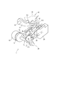
- FIG. 1 is a perspective view showing a shift-by-wire system according to the first embodiment.
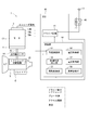
- FIG. 2 is a schematic configuration diagram showing a shift-by-wire system according to the first embodiment.
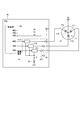
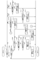
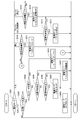
- FIG. 3 is a circuit diagram illustrating the ECU according to the first embodiment.
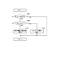
- FIG. 4 is a flowchart illustrating the abnormality detection process according to the first embodiment.
- FIG. 5 is a flowchart illustrating the drive mode selection process according to the first embodiment.
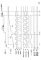
- FIG. 6 is a time chart illustrating motor drive control according to the first embodiment.
- FIG. 7 is a time chart illustrating motor drive control according to the first embodiment.
- FIG. 8 is a flowchart illustrating the drive mode selection process according to the second embodiment.
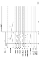
- FIG. 9 is a time chart illustrating motor drive control according to the second embodiment.
- the motor control device will be described with reference to the drawings.
- substantially the same configuration will be designated by the same reference numerals and description thereof will be omitted.
- the motor control device according to the first embodiment is shown in FIGS. 1 to 7.
- the shift-by-wire system 1 includes a motor 10, a shift range switching mechanism 20, a parking lock mechanism 30, an ECU 40 as a motor control device, and the like.
- the motor 10 rotates by being supplied with electric power from a battery mounted on a vehicle (not shown), and functions as a drive source for the shift range switching mechanism 20.
- the motor 10 of the present embodiment is a switched reluctance motor and has a motor winding 11 wound around a stator (not shown).
- the motor winding 11 has a U-phase winding 111, a V-phase winding 112, and a W-phase winding 113, and is connected by a connection portion 115 (see FIG. 3).
- the encoder 13 which is a rotation angle sensor detects the rotation position of a rotor (not shown) of the motor 10.
- the encoder 13 is, for example, a magnetic rotary encoder, which is composed of a magnet that rotates integrally with the rotor, a Hall IC for magnetic detection, and the like.
- the encoder 13 outputs an encoder signal, which is a pulse signal, at predetermined angles in synchronization with the rotation of the rotor.
- the speed reducer 14 is provided between the motor shaft of the motor 10 and the output shaft 15, and decelerates the rotation of the motor 10 to output to the output shaft 15. As a result, the rotation of the motor 10 is transmitted to the shift range switching mechanism 20.
- the output shaft 15 is provided with an output shaft sensor 16 that detects the angle of the output shaft 15.
- the output shaft sensor 16 is, for example, a potentiometer.
- the shift range switching mechanism 20 has a detent plate 21, a detent spring 25, a detent roller 26, and the like, and applies the rotational driving force output from the speed reducer 14 to the manual valve 28 and the manual valve 28. It is transmitted to the parking lock mechanism 30.
- the detent plate 21 is fixed to the output shaft 15 and driven by the motor 10.
- the detent plate 21 is provided with a pin 24 that projects parallel to the output shaft 15.
- the pin 24 is connected to the manual valve 28.
- the shift range switching mechanism 20 converts the rotational motion of the motor 10 into a linear motion and transmits it to the manual valve 28.
- the manual valve 28 is provided on the valve body 29.
- valleys 22 corresponding to each range of P (parking), R (reverse), N (neutral), and D (drive) are formed.
- the detent spring 25 is a plate-shaped member that can be elastically deformed, and a detent roller 26 is provided at the tip thereof.
- the detent spring 25 urges the detent roller 26 toward the center of rotation of the detent plate 21.
- the detent spring 25 is elastically deformed, and the detent roller 26 moves between the valleys 22.
- the swing of the detent plate 21 is regulated, the axial position of the manual valve 28 and the state of the parking lock mechanism 30 are determined, and the automatic transmission The shift range of 5 is fixed.
- the parking lock mechanism 30 has a parking rod 31, a cone 32, a parking lock pole 33, a shaft portion 34, and a parking gear 35.
- the parking rod 31 is formed in a substantially L shape, and one end 311 side is fixed to the detent plate 21.
- a cone 32 is provided on the other end 312 side of the parking rod 31. The cone 32 is formed so that the diameter is reduced toward the other end 312 side.
- the parking lock pole 33 comes into contact with the conical surface of the conical body 32 and is provided so as to be swingable around the shaft portion 34.
- a convex portion 331 that can mesh with the parking gear 35 is provided.
- the parking gear 35 is provided on an axle (not shown) so as to be able to mesh with the convex portion 331 of the parking lock pole 33.
- the rotation of the axle is restricted.
- the shift range is the NotP range, which is a range other than the P range
- the parking gear 35 is not locked by the parking lock pole 33, and the rotation of the axle is not hindered by the parking lock mechanism 30.
- the shift range is the P range
- the parking gear 35 is locked by the parking lock pole 33, and the rotation of the axle is restricted.
- the ECU 40 includes a driver circuit 41, a voltage detection unit 43, a current detection unit 45, a control unit 50, and the like. In FIG. 2, the description of the voltage detection unit 43 and the current detection unit 45 is omitted.
- the driver circuit 41 has three switching elements 411 to 413, and switches the energization of the windings 111 to 113.
- the switching elements 411 to 413 of the present embodiment are MOSFETs, and are provided between the windings 111 to 113 of each phase and the ground.
- connection portion 115 The windings 111 to 113 of the motor winding 11 are connected by the connection portion 115. Power is supplied to the connection portion 115 from the battery via the power supply line.
- the power supply line is provided with a relay unit 46 (see FIG. 2), and power is supplied to the connection unit 115 when the relay unit 46 is turned on.
- the voltage detection unit 43 includes a U-phase terminal voltage detection unit 431, a V-phase terminal voltage detection unit 432, and a W-phase terminal voltage detection unit 433.
- the U-phase terminal voltage detection unit 431 detects the U-phase terminal voltage Vu
- the V-phase terminal voltage detection unit 432 detects the V-phase terminal voltage Vv
- the W-phase terminal voltage detection unit 433 detects the W-phase terminal voltage Vw. ..
- the current detection unit 45 detects the current applied to the motor winding 11.
- the current detection unit 45 of this embodiment is a shunt resistor.
- the control unit 50 is mainly composed of a microcomputer or the like, and internally includes a CPU, ROM, RAM, I / O, and a bus line connecting these configurations, which are not shown.
- Each process in the control unit 50 may be software processing by executing a program stored in advance in a physical memory device such as a ROM (that is, a readable non-temporary tangible recording medium) on the CPU. It may be hardware processing by a dedicated electronic circuit.
- the control unit 50 includes an angle calculation unit 51, a target angle setting unit 52, a drive control unit 53, a voltage acquisition unit 56, a current acquisition unit 57, an abnormality diagnosis unit 58, and the like.
- the angle calculation unit 51 counts the pulse edges of each phase of the encoder signal output from the encoder 13 and calculates the encoder count value ⁇ en.
- the encoder count value ⁇ en is a value corresponding to the rotation position of the motor 10 and corresponds to the “motor angle”.
- the target angle setting unit 52 sets a target count value ⁇ cmd, which is a target position for stopping the motor 10.
- the target count value ⁇ cmd is set so that the detent roller 26 fits into the valley portion 22 according to the target shift range.
- the drive control unit 53 controls the drive of the motor 10 so that the encoder count value ⁇ en becomes the target count value ⁇ cmd. Specifically, the drive control unit 53 controls the on / off operation of the switching elements 411 to 413 by generating each phase command and outputting it to the driver circuit 41.
- the voltage acquisition unit 56 acquires the terminal voltages Vu, Vv, and Vw from the voltage detection unit 43.
- the current acquisition unit 57 acquires the voltage on the driver circuit 41 side of the current detection unit 45 as a detection value related to the motor current Im.
- the U-phase terminal voltage Vu is such that the battery voltage Vb and the switching element 411 are turned on when the switching element 411 is off.
- the ground potential is Vg.
- the terminal voltages Vv and Vw are the battery voltage Vb when the switching elements 412 and 413 are off, and the ground potential Vg when the switching elements 412 and 413 are on.
- the ground potential Vg is 0.
- the abnormality diagnosis unit 58 diagnoses the abnormality of the shift-by-wire system 1.
- the abnormality of the shift-by-wire system 1 includes an encoder abnormality which is an abnormality of the encoder 13 and an abnormality of the energization system.
- an abnormality of the energization system an abnormality of non-conduction due to an open failure of the switching elements 411 to 413 will be described.
- the non-conductability abnormality is not limited to the abnormality of the switching elements 411 to 413 itself, but also includes a signal abnormality and a battery short of the windings 111 to 113 of each phase.
- the U-phase abnormality determination will be mainly described.
- the encoder count value ⁇ en when the encoder count value ⁇ en is stagnant during the shift range switching, it is determined whether the encoder is abnormal or the continuity is impossible. Specifically, when the energization indicating phase when the encoder count value ⁇ en is stagnant is the U phase, if the U phase terminal voltage Vu is 0, the energization system is normal and it is determined that the encoder is abnormal. In this case, since the energization system is normal, the motor 10 is driven by the open drive for switching the energization phase at predetermined time intervals without using the encoder count value ⁇ en, and the range switching is continued.
- the energizing phase when the encoder count value ⁇ en is stagnant is the U phase
- the U phase terminal voltage Vu is the battery voltage Vb
- the energization to the motor 10 is turned off. do.
- the detent roller 26 is dropped into the nearest valley portion 22 by the load torque.
- step S501 is omitted and simply referred to as the symbol “S”. The same applies to the other steps.
- the abnormality diagnosis unit 58 determines whether or not the encoder 13 is stagnant. Here, if the encoder count value ⁇ en does not change in the determination time or the number of determinations, it is determined that the encoder 13 is stagnant. When it is determined that the encoder 13 is not stagnant (S501: NO), the processing after S502 is skipped. When it is determined that the encoder 13 is stagnant (S501: YES), the process proceeds to S502.
- the abnormality diagnosis unit 58 determines whether or not the terminal voltage V # of the energization indicating phase is equal to or higher than the voltage determination threshold value Vth. If the energization indicator phase is the U phase, the terminal voltage V # is the U phase terminal voltage Vu, and so on, and "#" means the energization indicator phase. Similar to S501, when the terminal voltage V # of the energization indicating phase continues to be at least the voltage determination threshold value Vth for the determination time or the number of determinations, an affirmative determination is made. The determination time and the number of determinations may be the same as or different from S501.
- the voltage determination threshold value Vth is a value between the ground potential Vg and the battery voltage Vb, and is set to an arbitrary value capable of separating the non-conductability abnormality and the encoder abnormality.
- the drive mode selection process of this embodiment will be described with reference to the flowchart of FIG. This process is executed by the control unit 50 at a predetermined cycle (for example, 1 [ms]) when the start switch of the vehicle such as the ignition switch is turned on.
- the fail modes of the present embodiment include a "fail (energization off) mode” for turning off the energization, a “fail (open) mode” for driving the motor 10 by open drive, and a “fail (stop)” for stopping the motor 10. ) Mode ”is included.
- control unit 50 determines the current drive mode.
- the drive mode is the standby mode, it shifts to S102, when it is the feedback mode, it shifts to S104, when it is the stop mode, it shifts to S110, and when it is the fail (open) mode, it shifts to S112 and fails (stops).
- the process proceeds to S114. Further, in the case of the fail (energization off) mode, the processing after S102 is skipped.
- the control unit 50 determines whether or not the target shift range has been changed. When it is determined that the target shift range has not been changed (S102: NO), the standby mode is continued. When it is determined that the target shift range has been changed (S102: YES), the process shifts to S103 and the drive mode is switched to the feedback mode. In the feedback mode, the drive of the motor 10 is feedback-controlled so that the encoder count value ⁇ en becomes the target count value ⁇ cmd. In the figure, etc., the feedback is described as "F / B" as appropriate.
- the control unit 50 determines whether or not the encoder abnormality is confirmed. When it is determined that the encoder abnormality is confirmed (S104: YES), the process shifts to S105 and the drive mode is switched to the fail (open) mode. If it is determined that the encoder abnormality has not been confirmed (S104: NO), the process proceeds to S106.
- the control unit 50 determines whether or not the non-conductability abnormality of the energization instruction phase is confirmed.
- S106: YES the process shifts to S107, the drive mode is set to fail (energization off), and the energization of the motor 10 is turned off.
- S106: NO the process proceeds to S108.
- the control unit 50 determines whether or not the motor 10 has reached the target angle.
- the encoder count value ⁇ en falls within a predetermined range (for example, ⁇ 2 counts) including the target count value ⁇ cmd, it is determined that the motor 10 has reached the target angle.
- the feedback mode is continued.
- the process proceeds to S109 and the drive mode is switched to the stop mode.
- the stop mode the motor 10 is stopped by energizing the two phases in a fixed phase according to the encoder count value ⁇ en.
- the control unit 50 determines whether or not the fixed phase energization is completed.
- the time during which the stationary phase energization is performed exceeds a predetermined time, it is determined that the stationary phase energization is completed.
- the predetermined time for continuing the fixed phase energization is set according to the time required for stopping the motor 10.
- the stop mode is continued.
- the process shifts to S111 and the drive mode is switched to the standby mode.
- the control unit 50 determines whether or not the motor 10 has reached the target angle. Since the encoder count value ⁇ en cannot be used in the fail (open) mode, the number of switching of the energized phase is counted for determination. When it is determined that the motor 10 has not reached the target angle (S112: NO), the fail (open) mode is continued. When it is determined that the motor 10 has reached the target angle (S112: YES), the process proceeds to S113, and the drive mode is switched to the fail (stop) mode. In the fail (stop) mode, the motor 10 is stopped by energizing the two phases in a fixed phase.
- the control unit 50 determines whether or not the fixed phase energization is completed, as in S110. If it is determined that the stationary phase energization is not completed (S114: NO), the fail (stop) mode is continued. When it is determined that the stationary phase energization is completed (S114: YES), the process shifts to S115, the drive mode is switched to fail (energization off), and the energization of the motor 10 is turned off.
- 6 and 7 show the drive mode, the motor angle, the energization instruction of each phase, the terminal voltage of each phase, the encoder abnormal state, and the non-conductability abnormal state from the upper stage.
- the motor angle the corresponding shift range is shown in parentheses. The same applies to FIG. 9 described later.
- the drive mode is switched from the standby mode to the feedback mode.
- the target count value ⁇ cmd is set so that the detent roller 26 fits into the valley portion 22 corresponding to the R range, and the motor 10 is driven by feedback control so that the encoder count value ⁇ en becomes the target count value ⁇ cmd.
- the energizing phase is switched by switching the energizing instruction according to the encoder count value ⁇ en.
- the terminal voltage of the phase in which the energization instruction is on is 0, and the terminal voltage of the phase in which the energization instruction is off is the battery voltage Vb.
- the encoder count value ⁇ en is stagnant at time x11.
- the energization instruction phase is the U phase
- the U phase terminal voltage Vu is 0,
- the motor current Im ⁇ is 0,
- a current is flowing through the motor winding 11. That is, since no abnormality has occurred in the energized system, the encoder abnormality is confirmed at the time x12 when the determination time Xa elapses from the stagnation of the encoder count value ⁇ en.
- the stagnation determination of the encoder 13 and the determination of the energized state are simultaneously determined. For example, the encoder stagnation is determined in the first determination time, and then the energized state is determined in the second determination time. You may try to do so.
- the drive mode is set to the fail (open) mode, the motor 10 is driven by the open drive, and the range switching is continued.
- the drive mode is switched to the fail (stop) mode, and the motor 10 is stopped by the fixed phase energization.
- the U phase and the V phase are energized.
- the drive mode is set to the fail (energization off) mode, and the energization of the motor 10 is stopped.
- the non-conductability abnormality is confirmed and the drive mode is switched to the fail (energization off) mode.
- the motor 10 rotates in the reverse direction due to the load torque, and the detent roller 26 is returned to the valley portion 22 corresponding to the P range at time x23.
- the ECU 40 of the present embodiment controls the drive of the motor 10 having the motor winding 11, and includes an angle calculation unit 51, a drive control unit 53, and an abnormality diagnosis unit 58. Be prepared.
- the angle calculation unit 51 acquires a detection value from the encoder 13 that detects the rotation angle of the motor 10 and calculates the encoder count value ⁇ en.
- the drive control unit 53 controls the drive of the motor 10 based on the encoder count value ⁇ en.
- the abnormality diagnosis unit 58 diagnoses the abnormality of the energized system while maintaining the energized state.
- the subsequent control can be appropriately performed according to the abnormal state. For example, when applied to the shift-by-wire system 1, the abnormality diagnosis can be performed more quickly than in the case where the abnormality determination is performed after the range switching is completed.
- the abnormality diagnosis unit 58 determines whether the detected abnormality of the encoder count value ⁇ en is due to an abnormality of the encoder 13 or an abnormality of the energization system based on the terminal voltages Vu, Vv, and Vw of the motor winding 11. do. This makes it possible to appropriately determine the abnormality that has occurred.
- the drive control unit 53 switches to the control not using the encoder count value ⁇ en and continues to drive the motor 10.
- the energization system is normal, the driving of the motor 10 can be continued without using the encoder count value ⁇ en. Further, in the shift-by-wire system 1, the range can be appropriately switched.
- the drive control unit 53 turns off the energization of the motor 10 when the abnormality of the encoder count value ⁇ en is due to the abnormality of the energization system. As a result, the driving of the motor 10 can be stopped promptly. Further, in the shift-by-wire system 1, it is possible to return to the range before the occurrence of the abnormality by the load torque.
- the abnormality diagnosis unit 58 detects an abnormality in the encoder count value ⁇ en, when the terminal voltage of the energization command phase, which is the phase instructing energization, is different from the normal state, the abnormality in the encoder count value ⁇ en is in the energization system. It is due to an abnormality, and the energization command phase is identified as the faulty phase. As a result, the abnormal portion can be appropriately identified.
- the second embodiment is shown in FIGS. 8 and 9.
- the fail mode of the present embodiment includes a fail (two-phase drive) mode in addition to each mode of the above-described embodiment.
- the control unit 50 determines the drive mode. When the drive mode is standby mode, it shifts to S201, when it is feedback mode, it shifts to S204, when it is stop mode, it shifts to S210, and when it is fail (open) mode and fail (two-phase drive) mode, it shifts to S212. In the case of the fail stop mode, the process proceeds to S214. Further, in the case of the fail (energization off) mode, the processing after S202 is skipped.
- S202 to S206 is the same as the processing of S102 to S106 in FIG.
- S206: YES the process shifts to S207 and the drive mode is switched to fail (two-phase drive).
- the motor 10 is driven by feedback control using two normal phases, the V phase and the W phase, and the shift range is switched.
- S208 to S211 is the same as the processing of S108 to S111 in FIG.
- S212 which shifts to the case where the drive mode is the fail (open) or fail (two-phase drive) mode
- the control unit 50 determines whether or not the motor 10 has reached the target angle.
- the encoder 13 since the encoder 13 is normal, it can be determined based on the encoder count value ⁇ en as in S108.
- the current drive mode is continued, and when it is determined that the motor 10 has reached the target angle (S212: YES), the process proceeds to S213.
- the control unit 50 switches the drive mode to the fail (stop) mode and stops the motor 10 by energizing the two phases in a fixed phase.
- the drive mode before the shift to the fail (stop) mode is the fail (two-phase drive) mode
- the normal two-phase fixed-phase energization is performed.
- the processing of S212 and S213 is the same as the processing of S112 and S113.
- the processing of S214 and S215 is the same as the processing of S114 and S115.
- the motor control process when a non-conducting abnormality occurs in the U phase will be described with reference to the time chart of FIG.
- the processing of time x30 to time x32 is the same as the processing of time x20 to time x22 in FIG.
- the drive mode is switched to the fail (two-phase drive) mode, and the motor 10 is driven by the two-phase drive using the V phase and the W phase.
- the drive mode is switched to the fail (stop) mode, and the motor 10 is turned on by the fixed phase energization that continues energizing the two phases of V phase and W phase. Stop it.
- the processing of the time x34 is the same as the processing of the time x14 in FIG.
- the drive control unit 53 does not use the specified fault phase, but switches to control for driving the motor 10 using a normal phase that is a phase other than the fault phase, and continues driving the motor 10.
- the driving of the motor 10 can be continued appropriately.
- the range can be appropriately switched. Moreover, the same effect as that of the above-described embodiment is obtained.
- the ECU 40 corresponds to the "motor control device”
- the encoder 13 corresponds to the "rotation angle sensor”
- the encoder count value ⁇ en corresponds to the "motor rotation angle”.
- the switching element of the driver circuit is provided between the winding of each phase and the ground.
- the switching element may be provided on the high potential side of the winding of each phase, or may be provided on both the high potential side and the ground side.
- the voltage determination threshold value Vth, the magnitude relationship, and the like can be appropriately changed according to the arrangement location of the switching element.
- an encoder is used as the rotation angle sensor.
- the rotation angle sensor may be a linear sensor such as a resolver as long as it can detect the rotation position of the rotor.
- a potentiometer is exemplified as an output shaft sensor.
- the output shaft sensor may be something other than a potentiometer, or the output shaft sensor may be omitted.
- the motor is a switched reluctance motor. In other embodiments, the motor may be something other than a switched reluctance motor, such as a DC brushless motor.
- the detent plate is provided with four valleys. In other embodiments, the number of valleys is not limited to four and may be any number. For example, the detent plate may have two valleys, and the P range and the NotP range may be switched. Further, the shift range switching mechanism, the parking lock mechanism, and the like may be different from those in the above embodiment. Further, in the above embodiment, the motor control device is applied to the shift range switching system. In other embodiments, the motor control device may be applied to an in-vehicle system other than the shift range switching system, or a motor drive system other than the in-vehicle.
- a speed reducer is provided between the motor shaft and the output shaft.
- the details of the speed reducer are not mentioned in the above embodiment, but for example, cycloid gears, planetary gears, spur gears that transmit torque from a speed reduction mechanism substantially coaxial with the motor shaft to the drive shaft, and these. Any configuration may be used, such as a combination of the above. Further, in another embodiment, the speed reducer between the motor shaft and the output shaft may be omitted, or a mechanism other than the speed reducer may be provided.
- the controls and methods thereof described in the present disclosure are realized by a dedicated computer provided by configuring a processor and memory programmed to perform one or more functions embodied by a computer program. May be done.
- the controls and methods thereof described in the present disclosure may be implemented by a dedicated computer provided by configuring the processor with one or more dedicated hardware logic circuits.
- the control unit and method thereof described in the present disclosure may be a combination of a processor and memory programmed to perform one or more functions and a processor composed of one or more hardware logic circuits. It may be realized by one or more dedicated computers configured.
- the computer program may be stored in a computer-readable non-transitional tangible recording medium as an instruction executed by the computer.
- the present disclosure is not limited to the above-described embodiment, and can be implemented in various forms without departing from the spirit of the present embodiment.
Landscapes
- Engineering & Computer Science (AREA)
- General Engineering & Computer Science (AREA)
- Power Engineering (AREA)
- Physics & Mathematics (AREA)
- General Physics & Mathematics (AREA)
- Mechanical Engineering (AREA)
- Gear-Shifting Mechanisms (AREA)
- Control Of Electric Motors In General (AREA)
- Control Of Ac Motors In General (AREA)
Priority Applications (3)
| Application Number | Priority Date | Filing Date | Title |
|---|---|---|---|
| DE112021000646.0T DE112021000646T5 (de) | 2020-01-22 | 2021-01-19 | Motorsteuervorrichtung |
| CN202180009671.2A CN114982126A (zh) | 2020-01-22 | 2021-01-19 | 马达控制装置 |
| US17/869,052 US12126292B2 (en) | 2020-01-22 | 2022-07-20 | Motor control device |
Applications Claiming Priority (2)
| Application Number | Priority Date | Filing Date | Title |
|---|---|---|---|
| JP2020-008475 | 2020-01-22 | ||
| JP2020008475A JP7400493B2 (ja) | 2020-01-22 | 2020-01-22 | モータ制御装置 |
Related Child Applications (1)
| Application Number | Title | Priority Date | Filing Date |
|---|---|---|---|
| US17/869,052 Continuation US12126292B2 (en) | 2020-01-22 | 2022-07-20 | Motor control device |
Publications (1)
| Publication Number | Publication Date |
|---|---|
| WO2021149657A1 true WO2021149657A1 (ja) | 2021-07-29 |
Family
ID=76992351
Family Applications (1)
| Application Number | Title | Priority Date | Filing Date |
|---|---|---|---|
| PCT/JP2021/001582 Ceased WO2021149657A1 (ja) | 2020-01-22 | 2021-01-19 | モータ制御装置 |
Country Status (5)
| Country | Link |
|---|---|
| US (1) | US12126292B2 (enExample) |
| JP (1) | JP7400493B2 (enExample) |
| CN (1) | CN114982126A (enExample) |
| DE (1) | DE112021000646T5 (enExample) |
| WO (1) | WO2021149657A1 (enExample) |
Families Citing this family (2)
| Publication number | Priority date | Publication date | Assignee | Title |
|---|---|---|---|---|
| JP7647278B2 (ja) * | 2021-04-16 | 2025-03-18 | 株式会社アイシン | シフト装置 |
| CN119001179B (zh) * | 2024-10-22 | 2025-01-24 | 常州合泰电机电器股份有限公司 | 一种用于步进电机的耐久测试装置及测试方法 |
Citations (4)
| Publication number | Priority date | Publication date | Assignee | Title |
|---|---|---|---|---|
| JPH0923675A (ja) * | 1995-07-03 | 1997-01-21 | Kayaba Ind Co Ltd | モータ駆動回路の故障検出装置 |
| JP2011182492A (ja) * | 2010-02-26 | 2011-09-15 | Denso Corp | 回転電機制御装置、および、これを用いた電動パワーステアリング装置 |
| JP2013118777A (ja) * | 2011-12-05 | 2013-06-13 | Toyota Motor Corp | インバータ用短絡故障検出装置及びモータ制御装置 |
| JP2019071726A (ja) * | 2017-10-10 | 2019-05-09 | 株式会社デンソー | シフトレンジ制御装置 |
Family Cites Families (8)
| Publication number | Priority date | Publication date | Assignee | Title |
|---|---|---|---|---|
| JP2004012299A (ja) * | 2002-06-06 | 2004-01-15 | Nippon Soken Inc | 同期回転機用回転角度検出装置 |
| JP4406453B2 (ja) * | 2007-10-03 | 2010-01-27 | トヨタ自動車株式会社 | シフト切替装置 |
| JP2012005286A (ja) * | 2010-06-18 | 2012-01-05 | Jtekt Corp | モータ制御装置及び電動パワーステアリング装置 |
| JP5942337B2 (ja) * | 2011-04-28 | 2016-06-29 | 株式会社ジェイテクト | 車両用操舵装置 |
| JP5511934B2 (ja) * | 2012-11-14 | 2014-06-04 | 三菱電機株式会社 | モータ制御装置、モータ制御方法および電動パワーステアリング装置 |
| JP6124112B2 (ja) * | 2013-02-12 | 2017-05-10 | 富士電機株式会社 | 交流電動機の制御装置及び制御方法 |
| JP2014192950A (ja) * | 2013-03-26 | 2014-10-06 | Denso Corp | 電力変換装置 |
| JP7167410B2 (ja) | 2018-07-11 | 2022-11-09 | ミネベアミツミ株式会社 | レーザ測長器 |
-
2020
- 2020-01-22 JP JP2020008475A patent/JP7400493B2/ja active Active
-
2021
- 2021-01-19 DE DE112021000646.0T patent/DE112021000646T5/de active Pending
- 2021-01-19 WO PCT/JP2021/001582 patent/WO2021149657A1/ja not_active Ceased
- 2021-01-19 CN CN202180009671.2A patent/CN114982126A/zh active Pending
-
2022
- 2022-07-20 US US17/869,052 patent/US12126292B2/en active Active
Patent Citations (4)
| Publication number | Priority date | Publication date | Assignee | Title |
|---|---|---|---|---|
| JPH0923675A (ja) * | 1995-07-03 | 1997-01-21 | Kayaba Ind Co Ltd | モータ駆動回路の故障検出装置 |
| JP2011182492A (ja) * | 2010-02-26 | 2011-09-15 | Denso Corp | 回転電機制御装置、および、これを用いた電動パワーステアリング装置 |
| JP2013118777A (ja) * | 2011-12-05 | 2013-06-13 | Toyota Motor Corp | インバータ用短絡故障検出装置及びモータ制御装置 |
| JP2019071726A (ja) * | 2017-10-10 | 2019-05-09 | 株式会社デンソー | シフトレンジ制御装置 |
Also Published As
| Publication number | Publication date |
|---|---|
| JP7400493B2 (ja) | 2023-12-19 |
| CN114982126A (zh) | 2022-08-30 |
| US20220360207A1 (en) | 2022-11-10 |
| DE112021000646T5 (de) | 2022-12-15 |
| US12126292B2 (en) | 2024-10-22 |
| JP2021118560A (ja) | 2021-08-10 |
Similar Documents
| Publication | Publication Date | Title |
|---|---|---|
| CN111201706B (zh) | 换挡挡位控制装置 | |
| CN109690147B (zh) | 换挡挡位控制装置 | |
| JP5958519B2 (ja) | 制御装置、および、これを用いたシフトバイワイヤシステム | |
| JP5831766B2 (ja) | 制御装置、および、これを用いたシフトバイワイヤシステム | |
| JP6863245B2 (ja) | シフトレンジ制御装置 | |
| US11112007B2 (en) | Shift range switching system | |
| US11313460B2 (en) | Shift range control device | |
| US12126292B2 (en) | Motor control device | |
| WO2019098313A1 (ja) | シフトレンジ切替システム | |
| WO2019088244A1 (ja) | シフトレンジ制御装置 | |
| WO2021075365A1 (ja) | モータ制御装置 | |
| WO2020080455A1 (ja) | シフトレンジ制御装置 | |
| US12143055B2 (en) | Abnormality monitoring apparatus | |
| CN112602265B (zh) | 换挡挡位控制装置 | |
| WO2024080244A1 (ja) | モータ制御装置 | |
| JP7067382B2 (ja) | シフトレンジ制御装置 | |
| JP2023012681A (ja) | モータ制御装置 | |
| WO2021039504A1 (ja) | シフトレンジ制御装置 |
Legal Events
| Date | Code | Title | Description |
|---|---|---|---|
| 121 | Ep: the epo has been informed by wipo that ep was designated in this application |
Ref document number: 21744616 Country of ref document: EP Kind code of ref document: A1 |
|
| 122 | Ep: pct application non-entry in european phase |
Ref document number: 21744616 Country of ref document: EP Kind code of ref document: A1 |