WO2021149239A1 - 遠心分離装置および分離板 - Google Patents
遠心分離装置および分離板 Download PDFInfo
- Publication number
- WO2021149239A1 WO2021149239A1 PCT/JP2020/002486 JP2020002486W WO2021149239A1 WO 2021149239 A1 WO2021149239 A1 WO 2021149239A1 JP 2020002486 W JP2020002486 W JP 2020002486W WO 2021149239 A1 WO2021149239 A1 WO 2021149239A1
- Authority
- WO
- WIPO (PCT)
- Prior art keywords
- separation
- centrifuge
- gap
- separation plate
- plate
- Prior art date
- Legal status (The legal status is an assumption and is not a legal conclusion. Google has not performed a legal analysis and makes no representation as to the accuracy of the status listed.)
- Ceased
Links
Images



Classifications
-
- B—PERFORMING OPERATIONS; TRANSPORTING
- B04—CENTRIFUGAL APPARATUS OR MACHINES FOR CARRYING-OUT PHYSICAL OR CHEMICAL PROCESSES
- B04B—CENTRIFUGES
- B04B1/00—Centrifuges with rotary bowls provided with solid jackets for separating predominantly liquid mixtures with or without solid particles
- B04B1/04—Centrifuges with rotary bowls provided with solid jackets for separating predominantly liquid mixtures with or without solid particles with inserted separating walls
- B04B1/08—Centrifuges with rotary bowls provided with solid jackets for separating predominantly liquid mixtures with or without solid particles with inserted separating walls of conical shape
-
- B—PERFORMING OPERATIONS; TRANSPORTING
- B04—CENTRIFUGAL APPARATUS OR MACHINES FOR CARRYING-OUT PHYSICAL OR CHEMICAL PROCESSES
- B04B—CENTRIFUGES
- B04B7/00—Elements of centrifuges
- B04B7/08—Rotary bowls
- B04B7/12—Inserts, e.g. armouring plates
- B04B7/14—Inserts, e.g. armouring plates for separating walls of conical shape
Definitions
- the present invention relates to a separation plate type centrifuge that separates solid components contained in a fluid to be treated, and a separation plate used in such a centrifuge.
- the centrifuge is provided with a large number of separation plates laminated in the direction of the rotation axis with strip-shaped gap pieces at predetermined intervals, and the fluid to be treated flowing into the separation gap is in the direction of the center of the separation plate.
- the solid content or the like is separated by moving toward the outer periphery of the separation plate by centrifugal sedimentation (see, for example, Patent Document 1).
- a centrifugal separator having a rotary container and a plurality of separation plates laminated inside the rotary container at predetermined intervals, and separating components having different specific densities contained in the fluid to be treated by centrifugal force.
- a gap portion for maintaining the predetermined distance is provided between the separation plate and the other laminated separation plates, and in the region between the gap portions in the plurality of separation plates and laminated. It is characterized in that at least one of a convex portion or a concave portion of a predetermined pattern is formed at a position overlapping with each other in the direction.
- the surface area of the separation plate is increased, so that the processing capacity can be easily increased.
- FIG. 2 is a cross-sectional view taken along the line III-III of FIG. It is a perspective view which shows the structure of another separation plate. It is a perspective view which shows the structure of the other separation plate. Further, it is a perspective view which shows the structure of another separation plate.
- a separating plate used for cleaning a stock solution which is a fluid to be treated such as a fuel oil and a lubricating oil for a marine diesel engine engine, and for classification and separation operations in various industrial fields.
- a centrifuge which is a type centrifuge, will be described.
- This separation plate type centrifuge is a vertical type centrifuge in which a large number of separation plates made of thin cone-shaped plates are stacked in a rotating body with a small gap along the axial direction of the guide cylinder. Therefore, sludge and the like are separated by centrifugal force in the rotating body.
- the sludge is a solid substance having a different specific gravity contained in the fluid to be treated, and more specifically, a solid content separated and deposited on the outermost diameter side of the rotating body by centrifugal force.
- a guide cylinder 105 that guides the undiluted solution supplied from the upper part toward the lowermost part of the rotary container and spreads toward the bottom.
- the guide cylinder 105 has a separation plate 201 which is mounted in a large number with a small gap in the axial direction.
- the undiluted solution introduced into the separation plate type centrifuge as described above rises in the gap between the separation plates 201 and flows, while the solid content having a large specific gravity moves to the sludge accumulation region and the oil (light liquid) rotates. It is separated to the center side of the container, and the separated water is discharged from a heavy liquid impeller provided at the top of the rotating container.
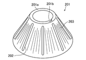
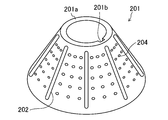
- the separation plate 201 (disc) has a cap shape made of stainless steel having a thickness of, for example, 0.5 mm, that is, the upper end thereof is cut off in a plane parallel to the open bottom surface, and the separation plate 201 (disk) is in the same plane on the inner peripheral side. It has a truncated cone shape provided with the ring-shaped portion 201a.
- a strip along the conical generatrix of the separation plate is provided as a gap for keeping the distance between the separation plates 201 at, for example, 0.6 mm when assembled to the separation plate type centrifuge.
- the shaped gap piece 202 is provided.
- a notch 201b is formed in a part of the inner peripheral side of the ring-shaped portion 201a, and the key 251 is inserted between the notch and the key groove 105a formed in the guide cylinder 105 shown in FIG. 1 to separate the ring-shaped portion 201a.
- the position of the plate 201 in the rotation direction is positioned (synchronized, detented).
- the gap piece 202 is not limited to a strip shape, but may be a circular shape or an oval shape. Further, not only the gap pieces are provided, but also irregularities different from the uneven portion 203 and the like, which will be described later, are formed so as not to overlap with the upper and lower separating plates 201, so that the distance between the separating plates 201 is kept predetermined. It may be made to be.
- the distance between the separating plates 201 is kept predetermined because the radius of curvature of the concave portion is smaller than the radius of curvature of the convex portion. May be made.
- the separation capacity (processing amount) when the fluid to be treated is treated by centrifugation between the separation plates 201 as described above is generally proportional to the sedimentation area, that is, the surface area of the separation plate 201. Therefore, in order to increase the separation capacity, the number of separation plates 201 is usually increased or the outer diameter is increased.
- an arc-shaped uneven portion 203 is formed in a region between the strip-shaped gap pieces 202. That is, for example, the uneven portion 203 in which the cross-sectional shape of the waveform as shown in FIG. 3 appears is formed.
- the surface area of the conical surface is large, so that the processing capacity can be easily increased. Therefore, for example, it is possible to easily obtain a high processing capacity when the particle size is very small.
- the separation plate 201 In order to increase the surface area of the separation plate 201, it is not limited to the arc-shaped uneven portion 203 as shown in FIG. 2, for example, the line segment-shaped uneven portion 203 along the conical generatrix as shown in FIG. Alternatively, as shown in FIG. 5, a curved uneven portion 203 such as a spiral shape may be formed. Further, discrete island-shaped uneven portions 204 as shown in FIG. 6 may be formed. Further, uneven portions having various shapes including these may be combined. Further, the concave portion and the convex portion are not limited to be formed, and only the concave portion or the convex portion may be formed.
- the density of the uneven portion 203 or the like may be different between the bottom side portion and the top side portion of the truncated cone shape of the separation plate 201. Specifically, for example, a region where the uneven portion 203 is not provided or a rough region is provided on the top side portion, and when the separation plate 201 is formed from the disk material by deep drawing, wrinkles are formed near the top. You may make it difficult for such things to occur. On the contrary, wrinkles and the like may be absorbed by providing the uneven portion 203 and the like.
Landscapes
- Centrifugal Separators (AREA)
Priority Applications (6)
| Application Number | Priority Date | Filing Date | Title |
|---|---|---|---|
| KR1020257028296A KR20250130856A (ko) | 2020-01-24 | 2020-01-24 | 원심분리 장치 |
| CN202080094006.3A CN115003417B (zh) | 2020-01-24 | 2020-01-24 | 离心分离装置 |
| KR1020227028732A KR20220125360A (ko) | 2020-01-24 | 2020-01-24 | 원심분리 장치 및 분리판 |
| JP2021572232A JP7311638B2 (ja) | 2020-01-24 | 2020-01-24 | 遠心分離機 |
| PCT/JP2020/002486 WO2021149239A1 (ja) | 2020-01-24 | 2020-01-24 | 遠心分離装置および分離板 |
| JP2023111337A JP7490119B2 (ja) | 2020-01-24 | 2023-07-06 | 遠心分離機 |
Applications Claiming Priority (1)
| Application Number | Priority Date | Filing Date | Title |
|---|---|---|---|
| PCT/JP2020/002486 WO2021149239A1 (ja) | 2020-01-24 | 2020-01-24 | 遠心分離装置および分離板 |
Publications (1)
| Publication Number | Publication Date |
|---|---|
| WO2021149239A1 true WO2021149239A1 (ja) | 2021-07-29 |
Family
ID=76991823
Family Applications (1)
| Application Number | Title | Priority Date | Filing Date |
|---|---|---|---|
| PCT/JP2020/002486 Ceased WO2021149239A1 (ja) | 2020-01-24 | 2020-01-24 | 遠心分離装置および分離板 |
Country Status (4)
| Country | Link |
|---|---|
| JP (2) | JP7311638B2 (https=) |
| KR (2) | KR20220125360A (https=) |
| CN (1) | CN115003417B (https=) |
| WO (1) | WO2021149239A1 (https=) |
Cited By (2)
| Publication number | Priority date | Publication date | Assignee | Title |
|---|---|---|---|---|
| US11660613B2 (en) * | 2016-10-31 | 2023-05-30 | Alfa Laval Corporate Ab | Separation disc for a centrifugal separator having spacing members with a triangular shape |
| WO2024122632A1 (ja) * | 2022-12-08 | 2024-06-13 | 三菱化工機株式会社 | 遠心分離装置および分離板 |
Citations (6)
| Publication number | Priority date | Publication date | Assignee | Title |
|---|---|---|---|---|
| JPS5114306B2 (https=) * | 1972-12-23 | 1976-05-08 | ||
| JPH01297158A (ja) * | 1987-12-07 | 1989-11-30 | Alfa Laval Separation Ab | 遠心分離機 |
| EP2050505A2 (de) * | 2007-10-17 | 2009-04-22 | GEA Westfalia Separator GmbH | Zentrifuge und Trennteller |
| US20110136649A1 (en) * | 2008-04-08 | 2011-06-09 | Alfa Laval Corporate Ab | Separation disc and separator |
| US20140221187A1 (en) * | 2011-05-02 | 2014-08-07 | Gea Mechanical Equipment Gmbh | Centrifuge |
| US20190247866A1 (en) * | 2016-10-31 | 2019-08-15 | Alfa Laval Corporate Ab | Stack of separation discs |
Family Cites Families (13)
| Publication number | Priority date | Publication date | Assignee | Title |
|---|---|---|---|---|
| GB190501606A (en) * | 1905-01-26 | 1906-01-04 | Arthur Freemore Spooner | Improvements in, and relating to, Centrifugal Separators. |
| JPS56144758A (en) * | 1980-04-11 | 1981-11-11 | Hitachi Ltd | Centrifugal separator |
| SE470348B (sv) * | 1992-06-16 | 1994-01-31 | Alfa Laval Separation Ab | Centrifugalseparator med separeringsskivor, vilka är försedda med strömningshinder |
| JP3006027U (ja) * | 1994-06-30 | 1995-01-17 | 三菱化工機株式会社 | 遠心分離機のシールパッキン |
| SE504094C2 (sv) * | 1995-03-06 | 1996-11-11 | Tetra Laval Holdings & Finance | Skivstapel av separationsskivor för centrifugalseparator |
| JP4745526B2 (ja) | 2001-05-11 | 2011-08-10 | 三菱化工機株式会社 | 分離板型遠心分離機およびこれに用いる分離板 |
| WO2004091800A1 (ja) * | 2003-04-15 | 2004-10-28 | Able Corporation | 分離板型遠心分離機 |
| CN101264468B (zh) * | 2008-04-22 | 2010-12-08 | 江苏工业学院 | 一种离心分离机碟片 |
| JP5242662B2 (ja) * | 2010-11-02 | 2013-07-24 | 定男 篠原 | 分離板型遠心分離機用分離板の製造方法 |
| EP2556895B1 (en) * | 2011-08-10 | 2018-06-27 | Alfa Laval Corporate AB | A separation disc for a centrifugal separator and a method for manufacturing the separation disc |
| CN103464308B (zh) * | 2013-09-18 | 2016-03-23 | 浙江索纳克生物科技有限公司 | 一种高性能碟式分离机转鼓 |
| EP3441145A4 (en) * | 2016-04-06 | 2019-12-11 | Tokyo Roki Co., Ltd. | OIL SEPARATOR |
| CN209271674U (zh) * | 2018-09-01 | 2019-08-20 | 合肥恒信汽车发动机部件制造有限公司 | 主动分离器用分离碟片及转子 |
-
2020
- 2020-01-24 KR KR1020227028732A patent/KR20220125360A/ko not_active Ceased
- 2020-01-24 CN CN202080094006.3A patent/CN115003417B/zh active Active
- 2020-01-24 JP JP2021572232A patent/JP7311638B2/ja active Active
- 2020-01-24 KR KR1020257028296A patent/KR20250130856A/ko active Pending
- 2020-01-24 WO PCT/JP2020/002486 patent/WO2021149239A1/ja not_active Ceased
-
2023
- 2023-07-06 JP JP2023111337A patent/JP7490119B2/ja active Active
Patent Citations (6)
| Publication number | Priority date | Publication date | Assignee | Title |
|---|---|---|---|---|
| JPS5114306B2 (https=) * | 1972-12-23 | 1976-05-08 | ||
| JPH01297158A (ja) * | 1987-12-07 | 1989-11-30 | Alfa Laval Separation Ab | 遠心分離機 |
| EP2050505A2 (de) * | 2007-10-17 | 2009-04-22 | GEA Westfalia Separator GmbH | Zentrifuge und Trennteller |
| US20110136649A1 (en) * | 2008-04-08 | 2011-06-09 | Alfa Laval Corporate Ab | Separation disc and separator |
| US20140221187A1 (en) * | 2011-05-02 | 2014-08-07 | Gea Mechanical Equipment Gmbh | Centrifuge |
| US20190247866A1 (en) * | 2016-10-31 | 2019-08-15 | Alfa Laval Corporate Ab | Stack of separation discs |
Cited By (4)
| Publication number | Priority date | Publication date | Assignee | Title |
|---|---|---|---|---|
| US11660613B2 (en) * | 2016-10-31 | 2023-05-30 | Alfa Laval Corporate Ab | Separation disc for a centrifugal separator having spacing members with a triangular shape |
| WO2024122632A1 (ja) * | 2022-12-08 | 2024-06-13 | 三菱化工機株式会社 | 遠心分離装置および分離板 |
| JPWO2024122632A1 (https=) * | 2022-12-08 | 2024-06-13 | ||
| JP7719583B2 (ja) | 2022-12-08 | 2025-08-06 | 三菱化工機株式会社 | 遠心分離装置および分離板 |
Also Published As
| Publication number | Publication date |
|---|---|
| KR20220125360A (ko) | 2022-09-14 |
| JP2023118918A (ja) | 2023-08-25 |
| KR20250130856A (ko) | 2025-09-02 |
| CN115003417A (zh) | 2022-09-02 |
| JP7490119B2 (ja) | 2024-05-24 |
| CN115003417B (zh) | 2026-03-31 |
| JP7311638B2 (ja) | 2023-07-19 |
| JPWO2021149239A1 (https=) | 2021-07-29 |
Similar Documents
| Publication | Publication Date | Title |
|---|---|---|
| US4262841A (en) | Truncated conical disc separator | |
| JP7490119B2 (ja) | 遠心分離機 | |
| US9475068B2 (en) | Smoothly accelerating channel inlet for centrifugal separator | |
| US11123753B2 (en) | Centrifugal separator with disc having regions of different densities of spacing members | |
| US11660607B2 (en) | Separation disc for a centrifugal separator | |
| CN107771103B (zh) | 具有盘堆叠的离心分离器 | |
| JPH01297158A (ja) | 遠心分離機 | |
| US3955754A (en) | Continuously operating centrifuge having a plurality of separating screens | |
| JP2025148588A (ja) | 遠心分離装置および分離板 | |
| KR101714353B1 (ko) | 임펠라 디스크형 원심분리기 | |
| US20020158008A1 (en) | Centrifuge | |
| JP2013086063A (ja) | 円筒型遠心分離機 | |
| JP2009514657A5 (ja) | 分離ディスク積層体を備える遠心機および分離ディスク | |
| JPWO2021149239A5 (https=) | ||
| US3108067A (en) | Centrifugal apparatus | |
| JP4450227B2 (ja) | 気液分離器及びオイルタンク構造 | |
| SU721126A1 (ru) | Вставка к сепаратору | |
| US957092A (en) | Liner for centrifugal liquid-separators. | |
| US20060207926A1 (en) | Centrifuge basket and centrifuge | |
| CN112437823B (zh) | 具有变化的深度轮廓的精磨机磨片 | |
| US837695A (en) | Centrifugal machine. | |
| SU1128988A1 (ru) | Центрифуга дл разделени суспензии в тонкой пленке | |
| US4383639A (en) | Arrangement for removing liquid from a rotating housing | |
| US3068618A (en) | Runner | |
| RU2098550C1 (ru) | Устройство для удаления нефтепродукта с водной поверхности |
Legal Events
| Date | Code | Title | Description |
|---|---|---|---|
| 121 | Ep: the epo has been informed by wipo that ep was designated in this application |
Ref document number: 20915449 Country of ref document: EP Kind code of ref document: A1 |
|
| ENP | Entry into the national phase |
Ref document number: 2021572232 Country of ref document: JP Kind code of ref document: A |
|
| ENP | Entry into the national phase |
Ref document number: 20227028732 Country of ref document: KR Kind code of ref document: A |
|
| NENP | Non-entry into the national phase |
Ref country code: DE |
|
| 122 | Ep: pct application non-entry in european phase |
Ref document number: 20915449 Country of ref document: EP Kind code of ref document: A1 |
|
| WWD | Wipo information: divisional of initial pct application |
Ref document number: 1020257028296 Country of ref document: KR |