WO2021149239A1 - Centrifugal separation device and separation plate - Google Patents
Centrifugal separation device and separation plate Download PDFInfo
- Publication number
- WO2021149239A1 WO2021149239A1 PCT/JP2020/002486 JP2020002486W WO2021149239A1 WO 2021149239 A1 WO2021149239 A1 WO 2021149239A1 JP 2020002486 W JP2020002486 W JP 2020002486W WO 2021149239 A1 WO2021149239 A1 WO 2021149239A1
- Authority
- WO
- WIPO (PCT)
- Prior art keywords
- separation
- centrifuge
- gap
- separation plate
- plate
- Prior art date
Links
Images


Classifications
-
- B—PERFORMING OPERATIONS; TRANSPORTING
- B04—CENTRIFUGAL APPARATUS OR MACHINES FOR CARRYING-OUT PHYSICAL OR CHEMICAL PROCESSES
- B04B—CENTRIFUGES
- B04B1/00—Centrifuges with rotary bowls provided with solid jackets for separating predominantly liquid mixtures with or without solid particles
- B04B1/04—Centrifuges with rotary bowls provided with solid jackets for separating predominantly liquid mixtures with or without solid particles with inserted separating walls
- B04B1/08—Centrifuges with rotary bowls provided with solid jackets for separating predominantly liquid mixtures with or without solid particles with inserted separating walls of conical shape
-
- B—PERFORMING OPERATIONS; TRANSPORTING
- B04—CENTRIFUGAL APPARATUS OR MACHINES FOR CARRYING-OUT PHYSICAL OR CHEMICAL PROCESSES
- B04B—CENTRIFUGES
- B04B7/00—Elements of centrifuges
- B04B7/08—Rotary bowls
- B04B7/12—Inserts, e.g. armouring plates
- B04B7/14—Inserts, e.g. armouring plates for separating walls of conical shape
Definitions
- the present invention relates to a separation plate type centrifuge that separates solid components contained in a fluid to be treated, and a separation plate used in such a centrifuge.
- the centrifuge is provided with a large number of separation plates laminated in the direction of the rotation axis with strip-shaped gap pieces at predetermined intervals, and the fluid to be treated flowing into the separation gap is in the direction of the center of the separation plate.
- the solid content or the like is separated by moving toward the outer periphery of the separation plate by centrifugal sedimentation (see, for example, Patent Document 1).
- a centrifugal separator having a rotary container and a plurality of separation plates laminated inside the rotary container at predetermined intervals, and separating components having different specific densities contained in the fluid to be treated by centrifugal force.
- a gap portion for maintaining the predetermined distance is provided between the separation plate and the other laminated separation plates, and in the region between the gap portions in the plurality of separation plates and laminated. It is characterized in that at least one of a convex portion or a concave portion of a predetermined pattern is formed at a position overlapping with each other in the direction.
- the surface area of the separation plate is increased, so that the processing capacity can be easily increased.
- FIG. 2 is a cross-sectional view taken along the line III-III of FIG. It is a perspective view which shows the structure of another separation plate. It is a perspective view which shows the structure of the other separation plate. Further, it is a perspective view which shows the structure of another separation plate.
- a separating plate used for cleaning a stock solution which is a fluid to be treated such as a fuel oil and a lubricating oil for a marine diesel engine engine, and for classification and separation operations in various industrial fields.
- a centrifuge which is a type centrifuge, will be described.
- This separation plate type centrifuge is a vertical type centrifuge in which a large number of separation plates made of thin cone-shaped plates are stacked in a rotating body with a small gap along the axial direction of the guide cylinder. Therefore, sludge and the like are separated by centrifugal force in the rotating body.
- the sludge is a solid substance having a different specific gravity contained in the fluid to be treated, and more specifically, a solid content separated and deposited on the outermost diameter side of the rotating body by centrifugal force.
- a guide cylinder 105 that guides the undiluted solution supplied from the upper part toward the lowermost part of the rotary container and spreads toward the bottom.
- the guide cylinder 105 has a separation plate 201 which is mounted in a large number with a small gap in the axial direction.
- the undiluted solution introduced into the separation plate type centrifuge as described above rises in the gap between the separation plates 201 and flows, while the solid content having a large specific gravity moves to the sludge accumulation region and the oil (light liquid) rotates. It is separated to the center side of the container, and the separated water is discharged from a heavy liquid impeller provided at the top of the rotating container.
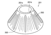
- the separation plate 201 (disc) has a cap shape made of stainless steel having a thickness of, for example, 0.5 mm, that is, the upper end thereof is cut off in a plane parallel to the open bottom surface, and the separation plate 201 (disk) is in the same plane on the inner peripheral side. It has a truncated cone shape provided with the ring-shaped portion 201a.
- a strip along the conical generatrix of the separation plate is provided as a gap for keeping the distance between the separation plates 201 at, for example, 0.6 mm when assembled to the separation plate type centrifuge.
- the shaped gap piece 202 is provided.
- a notch 201b is formed in a part of the inner peripheral side of the ring-shaped portion 201a, and the key 251 is inserted between the notch and the key groove 105a formed in the guide cylinder 105 shown in FIG. 1 to separate the ring-shaped portion 201a.
- the position of the plate 201 in the rotation direction is positioned (synchronized, detented).
- the gap piece 202 is not limited to a strip shape, but may be a circular shape or an oval shape. Further, not only the gap pieces are provided, but also irregularities different from the uneven portion 203 and the like, which will be described later, are formed so as not to overlap with the upper and lower separating plates 201, so that the distance between the separating plates 201 is kept predetermined. It may be made to be.
- the distance between the separating plates 201 is kept predetermined because the radius of curvature of the concave portion is smaller than the radius of curvature of the convex portion. May be made.
- the separation capacity (processing amount) when the fluid to be treated is treated by centrifugation between the separation plates 201 as described above is generally proportional to the sedimentation area, that is, the surface area of the separation plate 201. Therefore, in order to increase the separation capacity, the number of separation plates 201 is usually increased or the outer diameter is increased.
- an arc-shaped uneven portion 203 is formed in a region between the strip-shaped gap pieces 202. That is, for example, the uneven portion 203 in which the cross-sectional shape of the waveform as shown in FIG. 3 appears is formed.
- the surface area of the conical surface is large, so that the processing capacity can be easily increased. Therefore, for example, it is possible to easily obtain a high processing capacity when the particle size is very small.
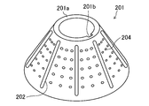
- the separation plate 201 In order to increase the surface area of the separation plate 201, it is not limited to the arc-shaped uneven portion 203 as shown in FIG. 2, for example, the line segment-shaped uneven portion 203 along the conical generatrix as shown in FIG. Alternatively, as shown in FIG. 5, a curved uneven portion 203 such as a spiral shape may be formed. Further, discrete island-shaped uneven portions 204 as shown in FIG. 6 may be formed. Further, uneven portions having various shapes including these may be combined. Further, the concave portion and the convex portion are not limited to be formed, and only the concave portion or the convex portion may be formed.
- the density of the uneven portion 203 or the like may be different between the bottom side portion and the top side portion of the truncated cone shape of the separation plate 201. Specifically, for example, a region where the uneven portion 203 is not provided or a rough region is provided on the top side portion, and when the separation plate 201 is formed from the disk material by deep drawing, wrinkles are formed near the top. You may make it difficult for such things to occur. On the contrary, wrinkles and the like may be absorbed by providing the uneven portion 203 and the like.
Abstract
Description
回転容器と、上記回転容器の内部に所定の間隔を空けて積層された複数の分離板とを有し、被処理流体に含まれる比重が異なる成分を遠心力により分離する遠心分離装置であって、
上記分離板の表面に、積層された他の分離板との間に上記所定の間隔を保つ間隙部が設けられるとともに、上記複数の分離板における、上記間隙部の間の領域で、かつ、積層方向に互いに重なる位置に、所定のパターンの凸部または凹部の少なくとも一方が形成されていることを特徴とする。 In order to achieve the above object, the present invention
A centrifugal separator having a rotary container and a plurality of separation plates laminated inside the rotary container at predetermined intervals, and separating components having different specific densities contained in the fluid to be treated by centrifugal force. ,
On the surface of the separation plate, a gap portion for maintaining the predetermined distance is provided between the separation plate and the other laminated separation plates, and in the region between the gap portions in the plurality of separation plates and laminated. It is characterized in that at least one of a convex portion or a concave portion of a predetermined pattern is formed at a position overlapping with each other in the direction.
分離板型遠心分離機は、
回転軸に取り付けられて高速回転する回転容器の内部に、図1に示すように上部から供給される原液を回転容器内の最下部に向けて末広がりに導く案内筒105と、
上記原液におけるスラッジ等の各成分を比重差により分離するために、上記案内筒105の軸方向に小間隙を有して多数積層されて装着された分離板201とを有している。 (Rough configuration of separation plate type centrifuge)
Separation plate type centrifuge
Inside the rotary container that is attached to the rotary shaft and rotates at high speed, as shown in FIG. 1, a
In order to separate each component such as sludge in the undiluted solution by the difference in specific gravity, the
分離板201(ディスク)は、図2に示すように、例えば厚さ0.5mmのステンレス鋼からなる笠状、すなわち上端部を開放底面に平行な平面で切除し、内周側に同平面内のリング状部201aが設けられた円錐台形状を有している。上記分離板201の外周面には、分離板型遠心分離機に組み付けられたときに各分離板201の間隔を例えば0.6mmに保つための間隙部として、分離板の円錐母線に沿った短冊状の間隙片202が設けられている。上記リング状部201aの内周側の一部には、切欠部201bが形成され、図1に示す案内筒105に形成されたキー溝105aとの間にキー251が挿入されることによって、分離板201の回転方向位置の位置決め(同期、回り止め)がなされるようになっている。なお、間隙片202は、短冊状に限らず、円形状や小判形などでもよい。さらに、間隙片が設けられるのに限らず、後述する凹凸部203等とは異なる凹凸が上下の分離板201で重ならないように形成されたりして、各分離板201の間隔が所定に保たれるようにされてもよい。また、凹凸が上下の分離板201で重なる位置に形成される場合でも、凸部の曲率半径よりも凹部の曲率半径の方が小さいことなどによって各分離板201の間隔が所定に保たれるようにされてもよい。 (Detailed configuration and separation action of separation plate 201)
As shown in FIG. 2, the separation plate 201 (disc) has a cap shape made of stainless steel having a thickness of, for example, 0.5 mm, that is, the upper end thereof is cut off in a plane parallel to the open bottom surface, and the separation plate 201 (disk) is in the same plane on the inner peripheral side. It has a truncated cone shape provided with the ring-
分離板201の表面積を大きくするためには、図2に示したような円弧状の凹凸部203に限らず、例えば図4に示すような円錐形状の母線に沿った線分状の凹凸部203や、図5に示すようならせん状などの曲線状の凹凸部203が形成されてもよい。また、図6に示すような離散した島状の凹凸部204が形成されたりしてもよい。さらに、これらを含む種々の形状の凹凸部が組み合わされたりしてもよい。また、凹部と凸部とが形成されるのに限らず、凹部だけや、凸部だけが形成されたりしてもよい。ここで、分離板201における円錐台形状の底部側部分と頂部側部分とで凹凸部203等の密度を異ならせたりしてもよい。具体的には、例えば、頂部側部分には凹凸部203が設けられていない領域や粗である領域が設けられて、分離板201を円板材料から深絞りによって形成する際に頂部付近でしわなどが生じにくいようにしたりしてもよい。逆に、凹凸部203等を設けることによって、しわなどが吸収されるようにしてもよい。 (Modification example)
In order to increase the surface area of the
105a キー溝
201 分離板
201a リング状部
201b 切欠部
202 間隙片
203 凹凸部
204 凹凸部
251 キー
105
Claims (5)
- 回転容器と、上記回転容器の内部に所定の間隔を空けて積層された複数の分離板とを有し、被処理流体に含まれる比重が異なる成分を遠心力により分離する遠心分離装置であって、
上記分離板の表面に、積層された他の分離板との間に上記所定の間隔を保つ間隙部が設けられるとともに、上記複数の分離板における、上記間隙部の間の領域で、かつ、積層方向に互いに重なる位置に、所定のパターンの凸部または凹部の少なくとも一方が形成されていることを特徴とする遠心分離装置。 A centrifugal separator having a rotary container and a plurality of separation plates laminated inside the rotary container at predetermined intervals, and separating components having different specific densities contained in the fluid to be treated by centrifugal force. ,
On the surface of the separation plate, a gap portion for maintaining the predetermined interval is provided between the separation plate and the other laminated separation plates, and in the region between the gap portions in the plurality of separation plates and laminated. A centrifuge device characterized in that at least one of a convex portion or a concave portion having a predetermined pattern is formed at a position overlapping with each other in the direction. - 請求項1の遠心分離装置であって、
上記分離板は、円錐台形状を有し、
上記所定のパターンは、上記分離板の円錐面の母線の方向の線分状、上記母線に交差する方向の線分に接する曲線状、および離散した島状の何れかに形成されていることを特徴とする遠心分離装置。 The centrifuge according to claim 1.
The separating plate has a truncated cone shape and has a truncated cone shape.
The predetermined pattern is formed in any of a line segment in the direction of the generatrix of the conical surface of the separation plate, a curved line tangent to the line segment in the direction intersecting the generatrix, and a discrete island shape. A featured centrifuge. - 請求項2の遠心分離装置であって、
上記凸部または凹部は、上記円錐台形状の底部側よりも頂部側の方が密度が小さく形成されていることを特徴とする遠心分離装置。 The centrifuge according to claim 2.
A centrifuge in which the convex or concave portion is formed to have a lower density on the top side than on the bottom side of the truncated cone shape. - 請求項2から請求項3のうち何れか1項の遠心分離装置であって、
上記間隙部は、上記円錐面の母線に沿った短冊状の間隙片であることを特徴とする遠心分離装置。 The centrifuge according to any one of claims 2 to 3.
The centrifuge is a centrifuge, wherein the gap is a strip-shaped gap piece along the generatrix of the conical surface. - 請求項1から請求項4のうち何れか1項の遠心分離装置の分離板であって、
表面に、上記間隙部が設けられるとともに、上記凸部または凹部の少なくとも一方が形成されていることを特徴とする遠心分離装置の分離板。 A separating plate for the centrifuge according to any one of claims 1 to 4.
A separation plate of a centrifuge device, characterized in that the gap portion is provided on the surface and at least one of the convex portion or the concave portion is formed.
Priority Applications (5)
| Application Number | Priority Date | Filing Date | Title |
|---|---|---|---|
| PCT/JP2020/002486 WO2021149239A1 (en) | 2020-01-24 | 2020-01-24 | Centrifugal separation device and separation plate |
| KR1020227028732A KR20220125360A (en) | 2020-01-24 | 2020-01-24 | Centrifuge device and separator plate |
| CN202080094006.3A CN115003417A (en) | 2020-01-24 | 2020-01-24 | Centrifugal separation device and separation plate |
| JP2021572232A JP7311638B2 (en) | 2020-01-24 | 2020-01-24 | centrifuge |
| JP2023111337A JP2023118918A (en) | 2020-01-24 | 2023-07-06 | centrifuge |
Applications Claiming Priority (1)
| Application Number | Priority Date | Filing Date | Title |
|---|---|---|---|
| PCT/JP2020/002486 WO2021149239A1 (en) | 2020-01-24 | 2020-01-24 | Centrifugal separation device and separation plate |
Publications (1)
| Publication Number | Publication Date |
|---|---|
| WO2021149239A1 true WO2021149239A1 (en) | 2021-07-29 |
Family
ID=76991823
Family Applications (1)
| Application Number | Title | Priority Date | Filing Date |
|---|---|---|---|
| PCT/JP2020/002486 WO2021149239A1 (en) | 2020-01-24 | 2020-01-24 | Centrifugal separation device and separation plate |
Country Status (4)
| Country | Link |
|---|---|
| JP (2) | JP7311638B2 (en) |
| KR (1) | KR20220125360A (en) |
| CN (1) | CN115003417A (en) |
| WO (1) | WO2021149239A1 (en) |
Cited By (1)
| Publication number | Priority date | Publication date | Assignee | Title |
|---|---|---|---|---|
| US11660613B2 (en) * | 2016-10-31 | 2023-05-30 | Alfa Laval Corporate Ab | Separation disc for a centrifugal separator having spacing members with a triangular shape |
Citations (6)
| Publication number | Priority date | Publication date | Assignee | Title |
|---|---|---|---|---|
| JPS5114306B2 (en) * | 1972-12-23 | 1976-05-08 | ||
| JPH01297158A (en) * | 1987-12-07 | 1989-11-30 | Alfa Laval Separation Ab | Centrifugal separator |
| EP2050505A2 (en) * | 2007-10-17 | 2009-04-22 | GEA Westfalia Separator GmbH | Centrifuge and separator disc |
| US20110136649A1 (en) * | 2008-04-08 | 2011-06-09 | Alfa Laval Corporate Ab | Separation disc and separator |
| US20140221187A1 (en) * | 2011-05-02 | 2014-08-07 | Gea Mechanical Equipment Gmbh | Centrifuge |
| US20190247866A1 (en) * | 2016-10-31 | 2019-08-15 | Alfa Laval Corporate Ab | Stack of separation discs |
Family Cites Families (4)
| Publication number | Priority date | Publication date | Assignee | Title |
|---|---|---|---|---|
| SE470348B (en) * | 1992-06-16 | 1994-01-31 | Alfa Laval Separation Ab | Centrifugal separator with separating discs which are provided with flow barriers |
| SE504094C2 (en) * | 1995-03-06 | 1996-11-11 | Tetra Laval Holdings & Finance | Disc stack of centrifugal separator discs |
| JP4745526B2 (en) | 2001-05-11 | 2011-08-10 | 三菱化工機株式会社 | Separator plate centrifuge and separator plate used therefor |
| JP5242662B2 (en) | 2010-11-02 | 2013-07-24 | 定男 篠原 | Separation plate manufacturing method for separation plate type centrifuge |
-
2020
- 2020-01-24 WO PCT/JP2020/002486 patent/WO2021149239A1/en active Application Filing
- 2020-01-24 JP JP2021572232A patent/JP7311638B2/en active Active
- 2020-01-24 KR KR1020227028732A patent/KR20220125360A/en unknown
- 2020-01-24 CN CN202080094006.3A patent/CN115003417A/en active Pending
-
2023
- 2023-07-06 JP JP2023111337A patent/JP2023118918A/en active Pending
Patent Citations (6)
| Publication number | Priority date | Publication date | Assignee | Title |
|---|---|---|---|---|
| JPS5114306B2 (en) * | 1972-12-23 | 1976-05-08 | ||
| JPH01297158A (en) * | 1987-12-07 | 1989-11-30 | Alfa Laval Separation Ab | Centrifugal separator |
| EP2050505A2 (en) * | 2007-10-17 | 2009-04-22 | GEA Westfalia Separator GmbH | Centrifuge and separator disc |
| US20110136649A1 (en) * | 2008-04-08 | 2011-06-09 | Alfa Laval Corporate Ab | Separation disc and separator |
| US20140221187A1 (en) * | 2011-05-02 | 2014-08-07 | Gea Mechanical Equipment Gmbh | Centrifuge |
| US20190247866A1 (en) * | 2016-10-31 | 2019-08-15 | Alfa Laval Corporate Ab | Stack of separation discs |
Cited By (1)
| Publication number | Priority date | Publication date | Assignee | Title |
|---|---|---|---|---|
| US11660613B2 (en) * | 2016-10-31 | 2023-05-30 | Alfa Laval Corporate Ab | Separation disc for a centrifugal separator having spacing members with a triangular shape |
Also Published As
| Publication number | Publication date |
|---|---|
| JP7311638B2 (en) | 2023-07-19 |
| JP2023118918A (en) | 2023-08-25 |
| CN115003417A (en) | 2022-09-02 |
| JPWO2021149239A1 (en) | 2021-07-29 |
| KR20220125360A (en) | 2022-09-14 |
Similar Documents
| Publication | Publication Date | Title |
|---|---|---|
| US4262841A (en) | Truncated conical disc separator | |
| US9475068B2 (en) | Smoothly accelerating channel inlet for centrifugal separator | |
| US11660613B2 (en) | Separation disc for a centrifugal separator having spacing members with a triangular shape | |
| JPH01297158A (en) | Centrifugal separator | |
| JP4794652B2 (en) | Separator plate centrifuge and its separator plate | |
| US10960412B2 (en) | Separation disc for a centrifugal separator having spot-formed spacing members | |
| US11660607B2 (en) | Separation disc for a centrifugal separator | |
| WO2021149239A1 (en) | Centrifugal separation device and separation plate | |
| US20190262843A1 (en) | A centrifugal separator | |
| JPS62102846A (en) | Inflow apparatus for centrifugal separator | |
| US3955754A (en) | Continuously operating centrifuge having a plurality of separating screens | |
| KR101714353B1 (en) | Impeller Disk typed Centrifugal Separator | |
| US20020158008A1 (en) | Centrifuge | |
| US7335302B2 (en) | Centrifuge basket and centrifuge | |
| JP4450227B2 (en) | Gas-liquid separator and oil tank structure | |
| US3108067A (en) | Centrifugal apparatus | |
| JPWO2021149239A5 (en) | ||
| SU721126A1 (en) | Insert to separator | |
| US957092A (en) | Liner for centrifugal liquid-separators. | |
| RU2007221C1 (en) | Centrifugal separator rotor | |
| US837695A (en) | Centrifugal machine. | |
| SU1128988A1 (en) | Centrifuge for separating suspensions in thin film | |
| RU2098550C1 (en) | Apparatus for removing petroleum products from water surface | |
| US4383639A (en) | Arrangement for removing liquid from a rotating housing | |
| CN113663823A (en) | Dish-shaped separating disc of centrifugal oil purifier |
Legal Events
| Date | Code | Title | Description |
|---|---|---|---|
| 121 | Ep: the epo has been informed by wipo that ep was designated in this application |
Ref document number: 20915449 Country of ref document: EP Kind code of ref document: A1 |
|
| ENP | Entry into the national phase |
Ref document number: 2021572232 Country of ref document: JP Kind code of ref document: A |
|
| ENP | Entry into the national phase |
Ref document number: 20227028732 Country of ref document: KR Kind code of ref document: A |
|
| NENP | Non-entry into the national phase |
Ref country code: DE |
|
| 122 | Ep: pct application non-entry in european phase |
Ref document number: 20915449 Country of ref document: EP Kind code of ref document: A1 |