WO2021149203A1 - モータ制御装置および空気調和装置 - Google Patents
モータ制御装置および空気調和装置 Download PDFInfo
- Publication number
- WO2021149203A1 WO2021149203A1 PCT/JP2020/002177 JP2020002177W WO2021149203A1 WO 2021149203 A1 WO2021149203 A1 WO 2021149203A1 JP 2020002177 W JP2020002177 W JP 2020002177W WO 2021149203 A1 WO2021149203 A1 WO 2021149203A1
- Authority
- WO
- WIPO (PCT)
- Prior art keywords
- amplitude
- power
- component
- inverter
- voltage
- Prior art date
- Legal status (The legal status is an assumption and is not a legal conclusion. Google has not performed a legal analysis and makes no representation as to the accuracy of the status listed.)
- Ceased
Links
Images







Classifications
-
- H—ELECTRICITY
- H02—GENERATION; CONVERSION OR DISTRIBUTION OF ELECTRIC POWER
- H02P—CONTROL OR REGULATION OF ELECTRIC MOTORS, ELECTRIC GENERATORS OR DYNAMO-ELECTRIC CONVERTERS; CONTROLLING TRANSFORMERS, REACTORS OR CHOKE COILS
- H02P29/00—Arrangements for regulating or controlling electric motors, appropriate for both AC and DC motors
- H02P29/02—Providing protection against overload without automatic interruption of supply
- H02P29/024—Detecting a fault condition, e.g. short circuit, locked rotor, open circuit or loss of load
- H02P29/0241—Detecting a fault condition, e.g. short circuit, locked rotor, open circuit or loss of load the fault being an overvoltage
-
- H—ELECTRICITY
- H02—GENERATION; CONVERSION OR DISTRIBUTION OF ELECTRIC POWER
- H02P—CONTROL OR REGULATION OF ELECTRIC MOTORS, ELECTRIC GENERATORS OR DYNAMO-ELECTRIC CONVERTERS; CONTROLLING TRANSFORMERS, REACTORS OR CHOKE COILS
- H02P29/00—Arrangements for regulating or controlling electric motors, appropriate for both AC and DC motors
- H02P29/02—Providing protection against overload without automatic interruption of supply
- H02P29/024—Detecting a fault condition, e.g. short circuit, locked rotor, open circuit or loss of load
- H02P29/028—Detecting a fault condition, e.g. short circuit, locked rotor, open circuit or loss of load the motor continuing operation despite the fault condition, e.g. eliminating, compensating for or remedying the fault
-
- H—ELECTRICITY
- H02—GENERATION; CONVERSION OR DISTRIBUTION OF ELECTRIC POWER
- H02P—CONTROL OR REGULATION OF ELECTRIC MOTORS, ELECTRIC GENERATORS OR DYNAMO-ELECTRIC CONVERTERS; CONTROLLING TRANSFORMERS, REACTORS OR CHOKE COILS
- H02P29/00—Arrangements for regulating or controlling electric motors, appropriate for both AC and DC motors
- H02P29/50—Reduction of harmonics
-
- H—ELECTRICITY
- H02—GENERATION; CONVERSION OR DISTRIBUTION OF ELECTRIC POWER
- H02P—CONTROL OR REGULATION OF ELECTRIC MOTORS, ELECTRIC GENERATORS OR DYNAMO-ELECTRIC CONVERTERS; CONTROLLING TRANSFORMERS, REACTORS OR CHOKE COILS
- H02P21/00—Arrangements or methods for the control of electric machines by vector control, e.g. by control of field orientation
- H02P21/14—Estimation or adaptation of machine parameters, e.g. flux, current or voltage
- H02P21/18—Estimation of position or speed
-
- H—ELECTRICITY
- H02—GENERATION; CONVERSION OR DISTRIBUTION OF ELECTRIC POWER
- H02P—CONTROL OR REGULATION OF ELECTRIC MOTORS, ELECTRIC GENERATORS OR DYNAMO-ELECTRIC CONVERTERS; CONTROLLING TRANSFORMERS, REACTORS OR CHOKE COILS
- H02P27/00—Arrangements or methods for the control of AC motors characterised by the kind of supply voltage
- H02P27/04—Arrangements or methods for the control of AC motors characterised by the kind of supply voltage using variable-frequency supply voltage, e.g. inverter or converter supply voltage
- H02P27/06—Arrangements or methods for the control of AC motors characterised by the kind of supply voltage using variable-frequency supply voltage, e.g. inverter or converter supply voltage using DC to AC converters or inverters
- H02P27/08—Arrangements or methods for the control of AC motors characterised by the kind of supply voltage using variable-frequency supply voltage, e.g. inverter or converter supply voltage using DC to AC converters or inverters with pulse width modulation
Definitions
- the present disclosure relates to a motor control device and an air conditioner that control the drive of a motor.
- a conventional air conditioner is equipped with an inverter that supplies an AC voltage to a motor to drive a compressor and a blower.
- the inverter supplies an AC voltage of an arbitrary frequency to the motor to control the rotation speed of the motor.
- the inverter uses a DC voltage as an input to generate an AC voltage.
- a rectifier circuit for converting an AC voltage of a power source into a DC voltage and a smoothing capacitor for smoothing the voltage are provided in front of the inverter.
- a smoothing capacitor requires a capacitance of several hundred to several thousand ⁇ F to smooth the voltage. For this reason, electrolytic capacitors that can secure a larger capacitance when compared with other capacitors with the same volume are often used.
- Electrolytic capacitors are often equipped with pressure valves to prevent failures due to increased pressure.
- the pressure valve When the pressure valve is activated, the amount of the electrolytic solution contained in the pressure valve is reduced, so that there is a problem that the capacitance is insufficient. Therefore, the voltage across the electrolytic capacitor (hereinafter referred to as the DC bus voltage) is detected so that the internal pressure or temperature does not reach the internal pressure or temperature at which the pressure valve operates, and when the amplitude of the pulsating wave exceeds the judgment value, the inverter
- Patent Document 1 Japanese Patent Application Laid-Open No. 2007-259629.
- the air conditioner disclosed in Japanese Patent Application Laid-Open No. 2007-259629 prevents an excessive ripple current from flowing through the electrolytic capacitor in an unbalanced state of the power supply in which different voltages are applied between the phases of the three-phase power supply voltage. .. Therefore, only the amplitude of the pulsating wave of the DC bus voltage is detected, and the output power of the inverter is suppressed so that the amplitude of the pulsating wave of the DC bus voltage is within the threshold value.
- the amplitude of the pulsating wave of the DC bus voltage may not necessarily increase even if the capacitance of the capacitor decreases. Therefore, even if the capacitance of the smoothing capacitor is reduced, the technique of JP-A-2007-259629 has a problem that it is difficult to accurately detect the state and the protection function does not operate.
- the present disclosure has been made to solve the above-mentioned problems, and is a motor control device that can realize monitoring of a smoothing capacitor with an inexpensive configuration without requiring additional parts or the like in an existing motor control device. It is an object of the present invention to provide an air conditioner.
- the motor control device receives AC power from AC power, outputs DC power, converts DC power to AC to drive the motor, and transmits DC power from the rectifier circuit to the inverter.
- a smoothing circuit that contains a reactor and a smoothing capacitor to suppress voltage fluctuations in the bus, a voltage detection circuit that detects the voltage of the bus, and a component that is six times the power supply frequency of the AC power supply extracted from the voltage of the bus.
- the first detection unit that detects the amount of change over time
- the power calculation unit that calculates the power value of the output power of the inverter, and the amount of change over time detected by the first detection unit and the power calculated by the power calculation unit. It is provided with a protection processing unit that estimates the capacitance of the smoothing capacitor using the value and determines that the smoothing capacitor is abnormal when the estimated capacitance becomes equal to or less than the first threshold value.
- a component 6 times the power supply frequency is extracted from the voltage of the bus applied to the smoothing capacitor, and the capacitance of the smoothing capacitor is estimated from the value and the output power of the inverter. This makes it possible to estimate the capacitance without being affected by the unbalanced power supply. Therefore, it is possible to accurately detect the decrease in capacitance and protect the device, so that the reliability of the entire device can be improved.
- FIG. 1 is a diagram showing a configuration of an air conditioner and a motor control device according to the first embodiment.
- the air conditioner 300 includes a refrigerant circuit 301 including a compressor 30, a condenser 31, an expansion device 32, and an evaporator 33.
- a motor 30M is built in the compressor 30 as a drive source. The motor 30M is controlled by the motor control device 100.
- the motor control device 100 includes a rectifier circuit 2, a smoothing circuit 3, an inverter 6, a current detection circuit 9, a motor control unit 10, and a capacitor monitoring unit 20.
- the capacitor monitoring unit 20 includes a CPU (Central Processing Unit) 21, a memory (ROM (Read Only Memory) and a RAM (Random Access Memory)) 22, an input / output device (not shown) for inputting various signals, and the like. It is composed.
- the CPU 21 expands the program stored in the ROM into a RAM or the like and executes the program.
- the program stored in the ROM is a program in which the processing procedure of the capacitor monitoring unit 20 is described.
- the capacitor monitoring unit 20 executes protection control of the inverter 6 according to these programs. This control is not limited to software processing, but can also be processed by dedicated hardware (electronic circuit).
- the motor control unit 10 is also configured to include a CPU and a memory in the same manner. The capacitor monitoring unit 20 and the motor control unit 10 may be one control device controlled by the same CPU.
- the compressor 30 compresses the refrigerant gas into a high-pressure gas, and the high-pressure gas refrigerant flows into the condenser 31.
- the condenser 31 heat is released from the refrigerant, and the high-pressure gas refrigerant condenses into a high-pressure liquid refrigerant.
- the high-pressure liquid refrigerant flows to the expansion device 32.
- the expansion device 32 the high-pressure liquid refrigerant is depressurized, and the low-pressure liquid refrigerant flows to the evaporator 33.
- the liquid refrigerant evaporates, and a cooling action of removing heat from the surroundings is performed.
- the evaporated gas refrigerant returns to the compressor 30, and the refrigerant circuit is established.
- the air conditioner 300 can switch between cooling and heating when the flow direction of the refrigerant is reversed by a four-way valve (not shown) or the like.
- the motor control device 100 can control the rotation speed of the motor 30M so as to have an arbitrary rotation speed.
- the motor control device 100 is not limited to the compressor of the air conditioner, and may be connected to a load-side blower provided in the indoor unit or may be connected to a heat source-side blower provided in the outdoor unit.
- the motor 30M controlled by the motor control device 100 is provided in the air conditioner will be described, but the device provided with the motor is not limited to the air conditioner.
- the rectifier circuit 2 converts the AC power supplied from the three-phase AC power supply 1 into DC power.
- the rectifier circuit 2 includes diode elements 2a to 2f for rectifying the current flow in one direction.
- the DC power rectified by the rectifier circuit 2 is smoothed by the smoothing circuit 3 and output to the bus.
- the smoothing circuit 3 smoothes the pulsating component of the DC bus voltage rectified by the rectifier circuit 2 and the reactor 4 provided to smooth the current flowing through the power supply and suppress the harmonic current and the inrush current, and provides a stable DC voltage. It is provided with a smoothing capacitor 5 provided for generation.
- an aluminum electrolytic capacitor (hereinafter referred to as an electrolytic capacitor) that can secure a large capacitance per the same volume and has a withstand voltage is often used.
- the electrolytic capacitor contains an electrolytic solution containing ethylene glycol or the like as a main solvent, and has a structure in which an electrolytic paper impregnated with the electrolytic solution is sandwiched between an anode and a cathode, and has a large capacitance in a small volume.
- the inverter 6 receives the DC bus voltage Vdc, which is the voltage across the smoothing capacitor 5, as an input.
- the inverter 6 includes six switching elements 6a to 6f inside.
- Each of the switching elements 6a to 6f is a power semiconductor element such as an IGBT (Insulated Gate Bipolar Transistor), for example.
- the voltage output from the inverter 6 is determined by performing the switching operation of the six switching elements 6a to 6f during a period determined by the carrier frequency.
- the motor control unit 10 controls the switching timing of the switching elements 6a to 6f.
- the motor control unit 10 controls the rotation speed by using the information obtained by the voltage detection circuit 8 and the current detection circuit 9 in order to control the rotation speed of the motor 30M to an arbitrary value.
- the voltage detection circuit 8 detects the DC bus voltage Vdc, which is the voltage across the smoothing capacitor 5.
- the current detection circuit 9 (for example, U phase 9a and W phase 9b) detects the current flowing through the motor 30M.
- the rotation speed command value N_ref of the motor 30M set so as to obtain the desired refrigerating capacity is input to the motor control unit 10.
- the motor control unit 10 determines the voltage output by the inverter 6 according to the rotation speed command value N_ref.
- PWM Pulse Width Modulation
- the width of ON time and OFF time in the switching cycle is adjusted in order to apply an arbitrary voltage to the three-phase coil of the motor 30M.
- the motor control unit 10 When increasing the motor voltage Va input to the motor 30M, the motor control unit 10 outputs a voltage command value Va * that widens the pulse width to the inverter 6.
- the motor control unit 10 When the motor voltage Va is reduced, the motor control unit 10 outputs a voltage command value Va * that narrows the pulse width to the inverter 6.
- the voltage command value Va * is a value including a U-phase voltage command value Vu *, a V-phase voltage command value Vv *, and a W-phase voltage command value Vw *.
- FIG. 2 is a waveform diagram showing a line voltage waveform between the U and V phases actually output from the inverter 6.
- the line voltage is a pulsed voltage as shown in FIG. 2, and its maximum value is limited by the input voltage to the inverter 6, that is, the value of the DC bus voltage Vdc.
- the peak-to-peak of the line voltage is ⁇ Vdc to + Vdc.
- the motor control unit 10 generates a PWM signal to be given to the inverter 6 in order to control the motor 30M at an arbitrary rotation speed.
- the motor 30M is a permanent magnet synchronous motor using a permanent magnet for the rotor.
- the motor control unit 10 is configured to perform position sensorless control in which the magnet position is estimated and calculated inside the CPU and the rotation speed is controlled accordingly.
- the current flowing through the motor 30M is vectorically separated into a d-axis component interlinking with the rotor magnetic flux and a q-axis component orthogonal to the rotor magnetic flux, and each current value is used as a command value. Many of them perform feedback control so that they match.
- the former d-axis component current has an action of adjusting the magnetic flux with respect to the rotor magnetic flux, and is set to an arbitrary value in consideration of the efficiency of the motor 30M and the like.
- the latter q-axis component current is a component that contributes to the output torque of the motor 30M, and the motor output torque can be increased by increasing the value.
- the rotation speed of the motor 30M can be increased. Conversely, deceleration can be achieved by outputting a torque smaller than the load torque.
- feedback control is performed so that the q-axis component current becomes an appropriate value in a timely manner.
- FIG. 3 is a functional block diagram relating to rotational speed control of the motor control unit 10.
- the motor control unit 10 includes subtractors 11 and 13, a speed control PI processing unit 12, and a current control PI processing unit 14.
- PI proportional integration
- the difference between the rotation speed command value N_ref and the actual rotation speed N is calculated, and the time is proportionally multiplied by the difference.
- the sum of the integrated values is taken as the command value Iq_ref of the q-axis component current.
- the current information acquired by the current detection circuit 9 is separated into the d-axis current and the q-axis current with respect to the d-axis current command value and the q-axis current command value, and the command value is used.
- PI control is performed for the difference.
- the current Iq is matched with the command value Iq_ref by PI control. In this way, the rotation speed and the current value each work to match the command value, and as a result, the rotation speed control of the motor 30M can be realized.
- the load torque of the motor 30M is determined by the suction pressure and the discharge pressure of the compressor 30.
- the load torque increases as the suction pressure and discharge pressure increase.
- the actual rotation speed decreases.
- the motor control unit 10 estimates or detects a decrease in the actual rotation speed, and executes the above-mentioned rotation speed feedback control.
- the actual rotation speed N of the motor 30M can be maintained at the rotation speed command value N_ref.
- the load torque and the output torque that change depending on the external environment are adjusted so as to be balanced, and the actual rotation speed N of the motor 30M is made to follow an arbitrary rotation speed command value N_ref.
- the electric power consumed by the motor 30M is represented by the product of the load torque of the motor 30M and the rotation speed.
- the power consumption of the motor 30M that is, the output power of the inverter 6 can be reduced.
- the motor load torque is determined by the suction pressure and the discharge pressure of the compressor 30, but since they are linked with the operating conditions of the air conditioner 300, the motor control unit 10 operates them to arbitrary values. It is not possible. Therefore, the motor control unit 10 reduces the rotation speed in order to adjust the output power of the inverter 6.
- the load torque in the compressor 30 is as described above, but in other motors (for example, a fan), the motor load torque is known to be proportional to the square of the rotation speed, and is similar to the compressor 30. By lowering the rotation speed, the torque is lowered, and as a result, the output power of the inverter 6 can be lowered.
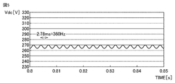
- the voltage applied to the smoothing capacitor 5 is a DC voltage, but the voltage after rectifying the three-phase AC power supply is a DC voltage in which a pulsating component 6 times the power supply frequency is superimposed as shown in FIG. Become.
- the current i flowing through the smoothing capacitor 5 is obtained by the following equation (1), and is obtained by multiplying the amount of time change of the voltage applied to the smoothing capacitor 5 with the capacitance of the smoothing capacitor 5.
- Capacitor current i Capacitance C ⁇ dv / dt ⁇ ⁇ (1)
- the pulsating component 6 when the three-phase AC power supply is rectified, a pulsating component 6 times the power supply frequency appears, but if the DC bus voltage after normal rectification, the amplitude of the pulsating wave is about several Vpp.
- the components can be selected so as to be equal to or less than the rated current value of the smoothing capacitor 5 even when converted into current. However, if there is an imbalance between the phases of the three-phase AC power supply, the pulsation of the voltage applied to the smoothing capacitor 5 increases, and the current tends to increase as represented by the equation (1).
- a pressure valve is generally installed in the electrolytic capacitor as a measure to mitigate the increase in internal pressure.
- Many electrolytic capacitors have a structure in which the pressure is released to the outside as the internal pressure increases. By doing so, it is possible to prevent component destruction even if the internal pressure rises. However, at the same time, the electrolytic solution is discharged to the outside, which results in a decrease in the capacitance of the smoothing capacitor 5.
- the electrolytic solution and other components contained inside the smoothing capacitor 5 are often composed of flammable substances. Therefore, when the electrolytic solution is released to the external environment in which oxygen exists, the risk of burning the equipment increases when the circuit is short-circuited or the like. Therefore, when the pressure valve of the electrolytic capacitor operates, it is necessary to stop the equipment immediately.
- the capacitor monitoring unit 20 detects a decrease in the capacitance of the smoothing capacitor 5 and safely stops the device.
- the inverter 6 is operated so as to suppress the output power.
- the difference is that the device is stopped if it is determined that the pressure valve has been activated by estimating the decrease in the capacitance of the smoothing capacitor 5.
- FIG. 4 is a block diagram showing the configuration of the capacitor monitoring unit 20.
- the capacitor monitoring unit 20 includes a 6f amplitude detection unit 40, a power calculation unit 41, a capacity calculation unit 42, and a protection processing unit 43.
- the 6f amplitude detection unit 40 extracts only a component 6 times the power supply frequency from the DC bus voltage.
- the power calculation unit 41 calculates the output power Pinv of the inverter 6.
- the capacitance calculation unit 42 estimates the capacitance of the smoothing capacitor 5 based on both information from the 6f amplitude detection unit 40 and the power calculation unit 41.
- the protection processing unit 43 determines the operation stop according to the value of the estimated capacitance value.
- FIG. 5 is a waveform diagram showing a pulsating wave having a component 6 times the power supply frequency appearing in the DC bus voltage Vdc.
- FIG. 6 is a waveform diagram showing a pulsating wave having a component twice the power supply frequency appearing in the DC bus voltage Vdc.
- the DC bus voltage Vdc applied to the smoothing capacitor 5 has a component 6 times the power supply frequency (hereinafter referred to as the 6f component) as shown in FIG. 5 as long as there is no imbalance in the three-phase AC power supply. It becomes a superimposed waveform.
- the DC bus voltage Vdc seems to have a component (called a 2f component) twice as shown in FIG. 6 superimposed in addition to a component 6 times the power supply frequency. Waveform.
- the 6f amplitude detection unit 40 functions to extract the 6f component from the DC bus voltage Vdc. Specifically, a bandpass filter that allows only certain frequency components to pass through, or a method such as Fast Fourier Transform (FFT) analysis that performs discrete Fourier transform to extract the superposition amount of each frequency component is used. Therefore, the 6f amplitude detection unit 40 may be realized.
- FFT Fast Fourier Transform
- the 6f amplitude detection unit 40 After extracting the waveform of the 6f component, the 6f amplitude detection unit 40 calculates the amplitude of the pulsating component and estimates the capacitance. For the calculation of the amplitude of the pulsating wave, the maximum value and the minimum value of the voltage of the waveform extracted inside the CPU within a certain period of time are stored.
- the value stored last time and the value detected this time are compared for each calculation cycle (sampling cycle). In the case of the maximum value, if the value detected this time is larger than the stored value, the stored value is updated. In the case of the minimum value, if the value detected this time is smaller than the stored value, the stored value is updated.
- the amplitude of the voltage of the 6f component is detected.
- the detection period needs to be set sufficiently longer than one pulsating cycle.
- One cycle is the reciprocal of 6f. Therefore, if the power supply frequency is 50 Hz, one cycle of the 6f component is 3.33 ms, and if the power supply frequency is 60 Hz, one cycle of the 6f component is 2.77 ms. It is possible to calculate the voltage amplitude by updating the stored value within a period sufficiently longer than one of these cycles.
- the amplitude of the voltage of the 6f component is detected as an example of the amount of change over time of the 6f component, but it is also possible to estimate the capacitor capacity by performing a time derivative process of the voltage or the like. Therefore, the capacitor capacity may be estimated using the time derivative value of the voltage of the 6f component as the amount of time change of the 6f component.
- the amplitude ⁇ Vdc (6f) of the 6f component is determined by the output power Pinv of the inverter 6, the inductance value of the reactor 4, and the capacitance of the smoothing capacitor 5.
- the inductance of the reactor 4 does not change significantly from the previously installed inductance value.
- the main factors that fluctuate are the output power Pinv of the inverter 6 and the capacitance of the smoothing capacitor 5.
- the 2f component is superimposed on the DC bus voltage Vdc in addition to the 6f component.
- the unbalance rate of the power supply voltage an index indicating the degree of unbalance of the voltage between the three phases
- the output power Pinv of the inverter 6 the inductance value of the reactor 4, and the capacitance of the smoothing capacitor 5.
- the main factors that fluctuate are the unbalance rate, the output power Pinv of the inverter 6, and the capacitance of the smoothing capacitor 5.
- a reference power frequency is required.
- the frequency of the three-phase AC power supply is often 50 Hz or 60 Hz, and it is detected in advance that it is either of these frequencies.
- Various methods have been proposed as a method for detecting the power supply frequency. For example, it is possible to use a process of detecting the timing when the AC power supply voltage becomes zero volt (hereinafter referred to as zero cross) and measuring the interval between a plurality of zero crosses with a CPU or the like to determine the frequency. In that case, a detection circuit for detecting zero cross is required separately.
- filter the DC bus voltage Vdc with two patterns, a bandpass filter that passes 300 Hz and a bandpass filter that passes 360 Hz, and determine the frequency from the magnitude of the pulsating component of the obtained two waveforms. It may be. For example, if the power supply frequency is 50 Hz, the pulsating component of 300 Hz, which is six times that frequency, becomes large, so that the frequency can be determined to be 50 Hz.
- the motor 30M is in operation, that is, the output power Pinv of the inverter 6 is at least a certain value.
- the output power Pinv is zero, there is no charge / discharge to the smoothing capacitor 5. That is, since the pulsation of the DC bus voltage Vdc disappears, the pulsation cannot be detected. Therefore, it is preferable to have a configuration in which the pulsation is determined in consideration of the value of the output power Pinv of the inverter 6 obtained by the power calculation unit 41 described later. By determining the frequency inside the capacitor monitoring unit 20 in this way, it is possible to realize a cheaper configuration.
- the power calculation unit 41 is provided to calculate the value of the output power Pinv of the inverter 6. As described above, the pulsation of the DC bus voltage Vdc appears more prominently when the output power Pinv of the inverter 6 is large. Therefore, in order to obtain the relationship between the capacitance of the smoothing capacitor 5 and the amplitude ⁇ Vdc (6f) of the 6f component, it is necessary to detect the output power Pinv of the inverter 6.
- the line output voltage V is a voltage value between lines (for example, between U and V phases) output from the inverter 6, and can be obtained from a voltage command value Va * calculated by the motor control unit 10.
- the output current I can be obtained from the output currents obtained by the current detection units 9a and 9b. Since the output current I is the current effective value and the information obtained by the current detection units 9a and 9b is an instantaneous value, it is necessary to convert the obtained instantaneous value of the current into an effective value and then obtain the power. be.
- the power factor cos ⁇ cos calculation is performed on the difference between the voltage phase and the current phase. For the difference between the voltage phase and the current phase, the phase difference between the voltage command value Va * and the instantaneous current obtained by the current detection unit 9a (or 9b) may be calculated.
- the power calculation unit 41 calculates the output power Pinv of the inverter 6 inside the CPU by using the voltage, current, and power factor information thus obtained.
- the capacitance calculation unit 42 calculates the capacitance of the smoothing capacitor 5 by combining the output power Pinv of the inverter 6 with the information obtained from the 6f amplitude detection unit 40 described above.
- the factors that change the amplitude ⁇ Vdc (6f) of the 6f component are mainly the change in the output power Pinv of the inverter 6 and the change in the capacitance of the smoothing capacitor 5.
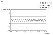
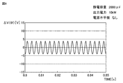
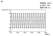
- FIGS. 7, 8 and 9 show pulsating waves of the 6f component of the DC bus voltage when the output power Pinv of the inverter 6 is set to a constant value (10 kW) and the capacity of the smoothing capacitor 5 is reduced.
- FIG. 7 is a waveform diagram showing a pulsating wave of the 6f component when the output power is 10 kW and the capacity is 4000 ⁇ F.
- FIG. 8 is a waveform diagram showing a pulsating wave of the 6f component when the output power is 10 kW and the capacity is 2000 ⁇ F.
- FIG. 9 is a waveform diagram showing a pulsating wave of the 6f component when the output power is 10 kW and the capacity is 1000 ⁇ F.
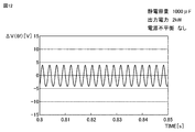
- FIGS. 10, 11 and 12 show pulsating waves of the 6f component of the DC bus voltage when the output power Pinv of the inverter 6 is set to a constant value (2 kW) and the capacity of the smoothing capacitor 5 is reduced.
- FIG. 10 is a waveform diagram showing a pulsating wave of the 6f component when the output power is 2 kW and the capacity is 4000 ⁇ F.
- FIG. 11 is a waveform diagram showing a pulsating wave of the 6f component when the output power is 2 kW and the capacity is 2000 ⁇ F.
- FIG. 12 is a waveform diagram showing a pulsating wave of the 6f component when the output power is 2 kW and the capacity is 1000 ⁇ F.
- the 6f voltage pulsation becomes smaller when the output power Pinv of the inverter 6 decreases even though the capacitances are the same. I understand. From this, in order to estimate the capacitance of the smoothing capacitor 5 from the 6f pulsating voltage, it is necessary to perform conversion according to the output power Pinv of the inverter 6. Therefore, in the present embodiment, the power calculation unit 41 is configured to calculate the value of the output power Pinv of the inverter 6.
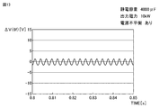
- FIG. 13 is a waveform diagram showing a pulsating wave of the 6f component when the output power is 10 kW and the capacity is 4000 ⁇ F when the power supply is unbalanced.
- FIG. 14 is a waveform diagram showing a pulsating wave of the 6f component when the output power is 10 kW and the capacity is 2000 ⁇ F when the power supply is unbalanced.
- FIG. 15 is a waveform diagram showing a pulsating wave of the 6f component when the output power is 10 kW and the capacity is 1000 ⁇ F when the power supply is unbalanced.
- FIGS. 7, 8 and 9 without power supply imbalance
- FIGS. 13, 14, and 15 with power supply imbalance
- the greatest feature of the present embodiment is that by detecting the amplitude of the voltage of only the 6f component, as shown in the comparison results of FIGS. 7 and 13, FIGS. 8 and 14, and 9 and 15.
- the point is that the capacitance can be estimated without being affected by external environmental factors such as unbalanced power supply or open phase of power supply.
- FIG. 16 is a diagram showing the relationship between the capacitance (horizontal axis) of the smoothing capacitor and the amplitude (vertical axis) of the pulsating wave of the bus voltage.
- the amplitude of is plotted.
- the amplitude of the DC bus voltage referred to here is obtained by storing the maximum value and the minimum value of the DC bus voltage Vdc in a certain period and obtaining the difference between the two.
- an LC circuit is formed by an inductance component such as the power supply wiring and the reactor 4 and a capacitance component of the smoothing capacitor 5 as an equivalent circuit when the device is viewed from the AC power supply 1.
- a phenomenon called resonance in which impedance becomes small occurs at a certain frequency.
- the amplitude of the pulsating wave is 60 V at the two points P1 and P2, and the capacitance cannot be uniquely determined with respect to the amplitude because the three-phase alternating current occurs when the power supply imbalance occurs. This is because the amplitude of the 2f component appears in addition to the 6f component in the DC bus voltage Vdc after the current is rectified.
- the amplitude ⁇ Vdc (6f) of the 6f component corresponding to the value of the output power Pinv of the inverter 6 is acquired in advance by simulation or the like. Then, the capacity calculation unit 42 compares the value of the output power Pinv obtained by the power calculation unit 41 with the amplitude ⁇ Vdc (6f) of the 6f component obtained by the 6f amplitude detection unit 40. In this way, the capacitance can be estimated.
- FIG. 17 is a diagram showing the relationship between the amplitude of the 6f component, the output power, and the capacitance of the smoothing capacitor 5. As shown in V1 to V4, it can be seen that the amplitude ⁇ V (6f) of the 6f component changes due to the change in capacitance even at the point where the output power of the same inverter 6 is 10 kW.
- the capacitance can be estimated to be 1000 ⁇ F. Further, as shown at point V2, if the amplitude ⁇ V (6f) is 6V, the capacitance can be estimated to be 2000 ⁇ F. As shown at point V3, if the amplitude ⁇ V (6f) is 2.5V, the capacitance can be estimated to be 3000 ⁇ F. As shown at point V4, if the amplitude ⁇ V (6f) is 2V, the capacitance can be estimated to be 4000 ⁇ F. By using such a relationship, the capacitance calculation unit 42 estimates the capacitance.
- the role of the protection processing unit 43 is to detect that the pressure valve has been activated by comparing the capacity of the smoothing capacitor 5 calculated by the capacity calculation unit 42 with a preset threshold value, and to detect the operation of the device. Is to protect. An example of how to set the threshold value is shown below.
- FIG. 18 is a diagram for explaining a method of setting a threshold value.
- the pressure valve operates at time t1
- the electrostatic urine volume gradually decreases with the passage of time.
- the threshold value (first threshold value Cth1). For example, a value of about several tens of percent of the normal value of the smoothing capacitor 5 is set as the threshold value Cth1. Then, when the estimated capacity falls below the threshold value Cth1, it is determined that the pressure valve has operated.
- the threshold value Cth1 is set on the line as shown in FIG. 18 with respect to the estimated capacitance value.
- the capacitance estimated from the amplitude ⁇ Vdc (6f) of the 6f component using the relationship of FIG. 17 becomes smaller than the capacitance indicated by the threshold value Cth1, it is determined that an abnormality has occurred in the smoothing capacitor 5.
- the smoothing circuit 3 and the inverter 6 may burn out, so it is necessary to stop the equipment immediately. .. Therefore, when the estimated capacitance C falls below the first threshold value Cth1, the capacitor monitoring unit 20 gives a stop signal of the motor control device to the motor control unit 10.
- the first threshold value Cth1 which is the lower limit value in this way, it is possible to immediately stop the device and at the same time detect that the capacitance has decreased due to aged deterioration of the smoothing capacitor 5. .. In addition to stopping the device, an alarm may be issued as the device to notify the replacement of parts.
- the capacitance of the smoothing capacitor 5 also changes depending on the temperature of the capacitor itself, but the main object of the present embodiment is to detect a capacitance decrease due to the operation of the pressure valve. .. It is assumed that the rate at which the capacitance decreases when the pressure valve operates is even faster than the rate at which the capacitance changes with temperature. Therefore, detecting the 6f component under the same output power condition and capturing the change is also an effective means for determining an abnormality of the device.
- the capacitance decreases in a short time.
- the pressure valve has been operated from the temporal change ⁇ C / ⁇ t of the capacitance so that it can be immediately determined as an abnormality.
- the second threshold value ⁇ Cth is provided for the time change of the capacitance (only in the decreasing direction) as shown in FIG. 18, and is higher than the second threshold value ⁇ Cth.
- the method of setting two threshold values has been described, but these are only examples, and the threshold values may be arbitrarily set according to the environment in which the device is installed or the usage conditions.
- the smoothing capacitor 5 corresponds to the value of the output power Pinv of the inverter 6.
- the capacitance C of is estimated. This makes it possible to accurately detect the capacitance C without being affected by external influences such as power supply imbalance. Further, since the filtering process is performed at 6 times the power supply frequency, it is possible to remove the switching noise of the inverter 6 and improve the accuracy of detecting the capacitance C. Further, in the present embodiment, it is possible to detect a short-term decrease in capacitance when the pressure valve is activated with an inexpensive configuration without requiring an additional detection circuit.
- FIG. 19 is a diagram showing the configuration of the capacitor monitoring unit 20A of the second embodiment.
- the configuration other than the capacitor monitoring unit 20A shown in FIG. 19 is omitted because the second embodiment is the same as the first embodiment, and only the differences will be described below.
- the capacitor monitoring unit 20A includes a protection processing unit 43A instead of the protection processing unit 43, and further includes an amplitude detection unit 44 and a 2f amplitude detection unit 45.
- the amplitude detection unit 44 in FIG. 19 detects the amplitude ⁇ Vdc of the pulsating wave of the DC bus voltage Vdc and outputs the value to the protection processing unit 43A.
- the amplitude detection unit 44 stores the maximum value and the minimum value of the DC bus voltage Vdc obtained by the voltage detection circuit 8 in a predetermined period in the CPU, and takes the difference between them to obtain the DC bus voltage Vdc.
- the amplitude ⁇ Vdc of the pulsating wave is detected.
- the specified period it is necessary to set a time sufficiently longer than the assumed pulsation cycle. For example, as a predetermined period, a time of several times the period of the 2f component of the power supply frequency may be set.
- the 6f amplitude detection unit 40 extracts only the component 6 times the power supply frequency with a bandpass filter, and detects the amplitude of the extracted 6 times component.
- the amplitude detection unit 44 calculates the amplitude of the waveform of the obtained DC bus voltage Vdc as it is without extracting the frequency component such as the 6-fold component.
- the 2f amplitude detection unit 45 extracts only the twice component (2f component) of the power supply frequency with a bandpass filter, and detects the amplitude of the extracted waveform.
- the 2f component is a component that occurs when the three-phase AC power supply is unbalanced or the power supply wiring is out of phase.
- the purpose of detecting the 2f component is to grasp the influence on the power supply side, and specifically, it is used for protection when the power supply imbalance rate deteriorates. The specific operation will be described later.
- the output power Pinv of the inverter 6 is suppressed when the value obtained by the amplitude detection unit 44 exceeds a preset threshold value.
- the protection processing unit 43A in the second embodiment also has a function of reducing the rotation speed command value N_ref of the motor control unit 10 in order to suppress the output power Pinv of the inverter 6.
- the stability as an air conditioner is ensured by reducing the rotation speed in a cycle of, for example, several seconds to several tens of seconds, instead of reducing the rotation speed instantaneously.
- the output power Pinv of the inverter 6 is calculated, and the capacitance of the smoothing capacitor 5 is estimated from the amplitude ⁇ Vdc (6f) of the 6f component.
- the output power of the inverter 6 since the output power of the inverter 6 is suppressed so that the amplitude of the pulsating wave of the DC bus voltage does not exceed the determination value, the output power of the inverter 6 may always change.
- the control is executed so as to reduce the output power of the inverter 6, so that the amplitude of the DC bus voltage does not increase and is kept constant.
- the capacitance C is estimated from the relationship between the output power Pinv of the inverter 6 and the amplitude ⁇ Vdc (6f) of the 6f component, but the output power Pinv of the inverter 6 is constantly changed. If this happens, the estimation result of the capacitance C will not be stable.
- the second embodiment is for solving such a problem, and is a case where it has a protection function for suppressing the output power of the inverter 6 against the amplitude of the pulsating wave as described in Patent Document 1.
- Another object of the present invention is to accurately detect a decrease in capacitance such that the pressure valve of the smoothing capacitor 5 operates, stop the operation, and improve the reliability of the device.
- FIG. 20 is a diagram showing the configuration of the protection processing unit 43A of the second embodiment.
- the protection processing unit 43A includes a rotation speed command adjustment unit 51, a stop unit 52, and a protection selection unit 50.
- the rotation speed command adjusting unit 51 is provided to suppress the output power of the inverter 6 as shown in Patent Document 1.
- the stop unit 52 controls to stop the device immediately.
- the protection selection unit 50 selects the function of either the rotation speed command adjustment unit 51 or the stop unit 52.
- the protection selection unit 50 As described in Patent Document 1, when the power supply imbalance occurs and the amplitude of the pulsating wave of the DC bus voltage exceeds the determination value, the rotation speed is normally increased by selecting the rotation speed command adjusting unit 51. It is suppressed.
- the amplitude ⁇ Vdc (6f) of the 6f component when the control is started is stored in the CPU, and the stored amplitude ⁇ Vdc (6f) of the 6f component is used as a threshold value for 6f.
- the rotation speed command adjusting unit 51 is operated so that the amplitude ⁇ Vdc (6f) of the component does not exceed the threshold value.
- the rotation speed is adjusted so that the amplitude of the pulsating wave of the DC bus voltage detected with respect to the preset threshold value does not exceed it.
- the second embodiment is different in that the rotation speed is adjusted with the amplitude ⁇ Vdc (6f) of the 6f component at the timing when the suppression control is started as a threshold value.
- the output power Pinv of the inverter 6 is adjusted so that the amplitude ⁇ Vdc (6f) of the 6f component becomes constant.
- the amplitude ⁇ Vdc (6f) of the 6f component is made constant.
- the output power Pinv of the inverter 6 is adjusted. As a result, if the value of the output power Pinv of the inverter 6 is equal to or less than the determination value, it can be determined that the capacity of the smoothing capacitor 5 has decreased.
- FIG. 21 is a diagram for explaining a determination of a decrease in the capacity of the smoothing capacitor.
- This relationship has also been described in FIG.
- the output power Pinv of the inverter 6 is controlled so that the amplitude ⁇ Vdc (6f) of the 6f component is constant
- the capacitance C of the smoothing capacitor 5 decreases
- the output power of the inverter 6 also decreases. Is obtained.
- the capacitance of the smoothing capacitor 5 when the capacitance of the smoothing capacitor 5 is 2000 ⁇ F, as shown at point V2, power of 10 kW or more is consumed for the amplitude ⁇ Vdc (6f) of the 6f component to be 8V.
- the capacitance C of the smoothing capacitor 5 drops to 1000 ⁇ F, the power Pinv must be lowered to 2.5 kW in order for the amplitude ⁇ Vdc (6f) of the 6f component to reach 8 V.
- the output power Pinv of the inverter 6 is adjusted so as not to exceed the threshold value with the amplitude ⁇ Vdc (6f) of the 6f component at the timing when the control is started as the threshold value.
- the value of the output power Pinv of the inverter 6 obtained by the power calculation unit 41 is lower than the power threshold value, it can be determined that the capacitance C of the smoothing capacitor 5 has decreased.
- the protection selection unit 50 stops the suppression control by the rotation speed command adjustment unit 51, and selects the stop unit 52 to switch the device. Stop it.
- the power threshold value the relationship as shown in FIG. 21 may be acquired in advance by analysis or the like, and the power threshold value may be set according to the value.
- the 2f component is superimposed, so that even if the capacitance C of the smoothing capacitor 5 decreases, the pulsating wave There is a case where the tendency of increasing the amplitude ⁇ Vdc of is not obtained. That is, when the output power Pinv is adjusted so as to keep the amplitude ⁇ Vdc of the pulsating wave of the DC bus voltage constant, the capacitance C of the smoothing capacitor 5 decreases even if the output power Pinv falls below the power threshold. I can't make a definite judgment that I did.
- the output is suppressed for the amplitude ⁇ Vdc (6f) of the 6f component, and a threshold value for the output power Pinv is set to ensure that the capacitance of the smoothing capacitor is increased. It becomes possible to judge that the decrease has occurred.
- the role of the 2f amplitude detection unit 45 will be described.
- the amplitude ⁇ Vdc (2f) of the 2f component increases.
- the current flowing through the smoothing capacitor 5 is largely due to the time change amount dv / dt of the voltage applied to the smoothing capacitor 5. Therefore, it goes without saying that even if only the 6f component is controlled to be constant, the current flowing through the smoothing capacitor 5 increases when the pulsation of the 2f component increases due to the deterioration of the power supply environment.
- the rotation speed command adjusting unit 51 adjusts the output power of the inverter 6 so that the amplitude ⁇ Vdc (6f) of the 6f component becomes constant. However, if the amplitude ⁇ Vdc (2f) of the 2f component increases despite the same output power, it is determined that the power supply environment has deteriorated. In this case, in order to reduce the stress on the smoothing capacitor 5, the rotation speed command adjusting unit 51 lowers the threshold value for the amplitude ⁇ Vdc (6f) of the 6f component stored in the memory of the CPU to suppress the output power Pinv. Try.
- the threshold value of the amplitude ⁇ Vdc (6f) of the 6f component is returned to the stored original value, assuming that the power supply environment has been improved. It may be controlled as follows.
- FIG. 22 is a flowchart for explaining the capacitor protection process executed in the second embodiment.
- the capacitor monitoring unit 20A measures the amplitude ⁇ Vdc (6f) of the 6f component in step S1 and determines the capacitance C of the smoothing capacitor 5 based on the relationship between the amplitude and the capacitance stored in advance. presume. Subsequently, the capacitor monitoring unit 20A determines in step S2 whether or not the capacitance C of the smoothing capacitor 5 is equal to or less than a predetermined threshold value.
- the capacitor monitoring unit 20A determines whether or not the time change amount ⁇ C / ⁇ t of the capacitance C is equal to or more than a predetermined threshold value.
- the capacitor monitoring unit 20A uses the motor.
- a stop command is output to the control unit 10. As a result, the motor 30M is stopped.
- the capacitor monitoring unit 20A When the time change amount ⁇ C / ⁇ t of the capacitance C is not equal to or more than a predetermined threshold value (NO in S3), the capacitor monitoring unit 20A has an amplitude ⁇ Vdc which is a fluctuation range of the voltage of the DC voltage bus in step S5. , Determine if it is less than a predetermined threshold.
- step S6 the capacitor monitoring unit 20A outputs a command to continue the operation of the motor 30M to the motor control unit 10.
- the threshold value for the output power is set in step S10.
- the capacitor monitoring unit 20A stores the amplitude ⁇ Vdc (6f) of the 6f component detected by the 6f amplitude detection unit 40 at that time.
- the amplitude ⁇ Vdc (6f) of the 6f component at the timing when ⁇ Vdc> the threshold value (S5 is NO) is stored, and the rotation speed is adjusted using that as a reference value.
- ⁇ Vdc and ⁇ Vdc (6f) increase as the motor load increases, so the control to reduce the rotation speed automatically works so that the amplitude ⁇ Vdc (6f) falls within the stored value (reference value). The rotation speed is adjusted to.
- a predetermined reference value may be provided for, for example, the amplitude ⁇ Vdc (6f) without using the stored value.
- step S8 the capacitor monitoring unit 20A executes a process of setting a determination threshold value for the amplitude ⁇ Vdc (6f) of the 6f component.
- step S8 first, an initial value stored in advance is set as a determination threshold value.
- the deterioration state of the power supply environment is estimated from the amplitude ⁇ Vdc (2f) of the 2f component detected by the 2f amplitude detection unit 45. If the amplitude ⁇ Vdc (2f) of the 2f component increases despite the output power of the same inverter 6, the capacitor monitoring unit 20A considers that the power supply environment has deteriorated with respect to the amplitude ⁇ Vdc (6f) of the 6f component. Decrease the stored threshold. As a result, the output power is suppressed after the subsequent process of adjusting the rotation speed command (S9), and the stress applied to the smoothing capacitor 5 is relieved. On the other hand, when the amplitude ⁇ Vdc (2f) is reduced, it is assumed that the power supply environment has been improved, and when the threshold value is lowered, the threshold value is returned to the original stored initial value.
- step S8 After the determination threshold value for the amplitude ⁇ V (6f) of the 6f component is set in step S8, the process of adjusting the rotation speed command is executed in step S9.
- step S9 the capacitor monitoring unit 20A outputs a command to the motor control unit 10 to adjust the rotation speed of the motor 30M so that the amplitude ⁇ V (6f) of the 6f component matches the determination threshold value. do.
- the capacitor monitoring unit 20A determines in step S10 whether or not the output power Pinv of the inverter 6 after adjusting the rotation speed is smaller than a predetermined threshold value. As described with reference to FIG. 21, when the rotation speed of the motor 30M is adjusted so that the amplitude ⁇ V (6f) of the 6f component becomes equal, the smaller the capacitance, the smaller the output Pinv.
- step S11 the capacitor monitoring unit 20A is the motor control unit. A command is output to 10 to continue the operation of the motor 30M.
- the motor control device calculates the amplitude ⁇ Vdc (6f) of the 6f component and the amplitude ⁇ Vdc (2f) of the 2f component. Then, the stress on the smoothing capacitor 5 due to the deterioration of the power supply environment detected by the 2f component is controlled so as to suppress the output without stopping the motor 30M (S7 to S11). On the other hand, if the capacitance of the smoothing capacitor 5 suddenly decreases (YES in S3) such that the pressure valve operates, it is detected by the amplitude ⁇ Vdc (6f) of the 6f component (S2, S3). , It is determined that the device is abnormal and operates to stop the operation (S4).
- the motor control device 100 includes a rectifier circuit 2, an inverter 6, a bus, a smoothing circuit 3, a first amplitude detection unit 40, a power calculation unit 41, and a protection processing unit. It includes 43.
- the rectifier circuit 2 receives AC power from AC power 1 and outputs DC power.
- the inverter 6 converts DC power into alternating current to drive the motor 30M.
- the bus transmits DC power from the rectifier circuit 2 to the inverter 6.
- the smoothing circuit 3 includes a reactor 4 and a smoothing capacitor 5, suppresses voltage fluctuations of the bus, and smoothes current fluctuations of the bus.
- the voltage detection circuit 8 detects the voltage of the bus.
- the first amplitude detection unit 40 detects the amount of time change of a component 6 times the power supply frequency of the AC power supply extracted from the voltage of the bus.
- the power calculation unit 41 calculates the power value Pinv of the output power of the inverter 6.
- the protection processing unit 43 estimates the capacitance C of the smoothing capacitor 5 using the amount of time change detected by the voltage detection circuit 8 and the power value calculated by the power calculation unit 41, and the estimated static capacity C is used. When the capacitance C becomes equal to or less than the first threshold value Cth1 (YES in S2), it is determined that the smoothing capacitor 5 is abnormal.
- the protection processing unit 43 determines that the smoothing capacitor 5 is abnormal, it executes protection processing such as outputting an alarm, controlling the load of the motor 30M to be reduced, stopping the motor 30M, and the like.
- the component 6 times the power supply frequency is extracted from the voltage of the bus applied to the smoothing capacitor 5, and the capacitance of the smoothing capacitor 5 is estimated from the value and the output power of the inverter 6. This makes it possible to estimate the capacitance without being affected by the unbalanced power supply. Therefore, it is possible to accurately detect the decrease in capacitance and protect the device, so that the reliability of the entire device can be improved.
- the protection processing unit 43 adds the smoothing capacitor 5 to the case where the estimated capacitance of the smoothing capacitor 5 is equal to or less than the first threshold value Cth1 (YES in S2).
- the amount of change ⁇ C / ⁇ t of the estimated capacitance per time becomes equal to or greater than the second threshold value ⁇ Cth (YES in S3), the motor 30M is stopped.
- the amount of change in the capacitance is also monitored to determine the deterioration of the smoothing capacitor 5, so that it is possible to detect the occurrence of an abnormality at an early stage and protect the motor 30M. It becomes.
- the first amplitude detection unit 40 calculates the first amplitude ⁇ Vdc (6f), which is the fluctuation range of the component 6 times, as the amount of change with time.
- the motor control device 100 further includes a second amplitude detection unit 44 that calculates the second amplitude ⁇ Vdc, which is the fluctuation range of the voltage of the bus.
- the protection processing unit 43A sets the first amplitude at the time when the second amplitude ⁇ Vdc exceeds the third threshold value as the fourth threshold value (S8), and the detected first amplitude ⁇ Vdc (6f) is the fourth.
- the output power of the inverter is suppressed so as not to exceed the threshold value (S9).
- the protection processing unit 43A stops the motor 30M when the output power Pinv of the inverter 6 is lower than the preset fifth threshold value (YES in S10).
- the motor control device 100 includes a third amplitude detection unit 45 that calculates a third amplitude ⁇ Vdc (2f), which is a fluctuation range of a component twice the power supply frequency of the AC power supply 1 extracted from the voltage of the bus. Further prepare.
- the protection processing unit 43A lowers the fourth threshold value when the third amplitude ⁇ Vdc (2f) increases.
- deterioration of the power supply environment can be detected by monitoring the fluctuation range of the component that is twice the power supply frequency. Then, when the power supply environment deteriorates, the output of the inverter 6 can be suppressed so as to reduce the stress on the smoothing capacitor 5.
- the protection processing unit 43A stores the lowered fourth threshold value when the increased third amplitude ⁇ Vdc (2f) is lowered when the fourth threshold value is lowered. Restores the original value that was set.
- the present disclosure relates to the air conditioner 300 in other aspects.
- the air conditioner 300 includes a compressor 30 that compresses and discharges the refrigerant, a condenser 31 that condenses the refrigerant by heat exchange, an expansion device 32 for depressurizing the refrigerant condensed by the condenser 31, and an expansion device.
- a refrigerant circuit 301 in which the refrigerant decompressed in 32 and an evaporator 33 that exchanges heat with air to evaporate the refrigerant are connected by a pipe, a motor 30M for driving the compressor 30, and any of the above motor control devices 100. And.
Landscapes
- Engineering & Computer Science (AREA)
- Power Engineering (AREA)
- Inverter Devices (AREA)
- Control Of Ac Motors In General (AREA)
Priority Applications (3)
| Application Number | Priority Date | Filing Date | Title |
|---|---|---|---|
| JP2021572203A JP7285969B2 (ja) | 2020-01-22 | 2020-01-22 | モータ制御装置および空気調和装置 |
| PCT/JP2020/002177 WO2021149203A1 (ja) | 2020-01-22 | 2020-01-22 | モータ制御装置および空気調和装置 |
| DE112020006578.2T DE112020006578T5 (de) | 2020-01-22 | 2020-01-22 | Motorsteuervorrichtung und Klimatisierungsvorrichtung |
Applications Claiming Priority (1)
| Application Number | Priority Date | Filing Date | Title |
|---|---|---|---|
| PCT/JP2020/002177 WO2021149203A1 (ja) | 2020-01-22 | 2020-01-22 | モータ制御装置および空気調和装置 |
Publications (1)
| Publication Number | Publication Date |
|---|---|
| WO2021149203A1 true WO2021149203A1 (ja) | 2021-07-29 |
Family
ID=76992734
Family Applications (1)
| Application Number | Title | Priority Date | Filing Date |
|---|---|---|---|
| PCT/JP2020/002177 Ceased WO2021149203A1 (ja) | 2020-01-22 | 2020-01-22 | モータ制御装置および空気調和装置 |
Country Status (3)
| Country | Link |
|---|---|
| JP (1) | JP7285969B2 (https=) |
| DE (1) | DE112020006578T5 (https=) |
| WO (1) | WO2021149203A1 (https=) |
Cited By (6)
| Publication number | Priority date | Publication date | Assignee | Title |
|---|---|---|---|---|
| CN116260103A (zh) * | 2022-12-22 | 2023-06-13 | 上海儒竞智控技术有限公司 | 基于母线电流采样检测输入缺相并保护的方法、系统、电子设备及介质 |
| JPWO2024084679A1 (https=) * | 2022-10-21 | 2024-04-25 | ||
| US20240264213A1 (en) * | 2021-10-05 | 2024-08-08 | Hitachi Industrial Equipment Systems Co., Ltd. | Power Conversion Apparatus, Deterioration Determination Method for Smoothing Capacitor |
| WO2025013744A1 (ja) * | 2023-07-12 | 2025-01-16 | 川崎重工業株式会社 | 供給電力算出方法、プログラムおよび供給電力算出装置 |
| EP4513036A4 (en) * | 2022-05-24 | 2025-04-23 | Mitsubishi Heavy Industries Thermal Systems, Ltd. | OPERATIONAL RECORDING SYSTEM, VEHICLE, OPERATIONAL RECORDING PROCEDURE AND OPERATIONAL RECORDING PROGRAM |
| US12618886B2 (en) * | 2021-10-05 | 2026-05-05 | Hitachi Industrial Equipment Systems Co., Ltd. | Power conversion apparatus, deterioration determination method for smoothing capacitor |
Families Citing this family (1)
| Publication number | Priority date | Publication date | Assignee | Title |
|---|---|---|---|---|
| LU504502B1 (de) * | 2023-06-13 | 2024-12-13 | Wilo Se | Verfahren zum positionsgeberlosen Starten einer permanenterregten Synchronmaschine |
Citations (4)
| Publication number | Priority date | Publication date | Assignee | Title |
|---|---|---|---|---|
| JP2009168587A (ja) * | 2008-01-16 | 2009-07-30 | Fujitsu General Ltd | 平滑コンデンサの異常検出回路及びこれを備えた電子機器 |
| JP2012205391A (ja) * | 2011-03-25 | 2012-10-22 | Toshiba Schneider Inverter Corp | インバータ装置及び平滑コンデンサの容量推定方法 |
| JP2012205392A (ja) * | 2011-03-25 | 2012-10-22 | Toshiba Schneider Inverter Corp | インバータ装置及び電解コンデンサの寿命時間推定方法 |
| JP2013242081A (ja) * | 2012-05-21 | 2013-12-05 | Fujitsu General Ltd | 空気調和機 |
Family Cites Families (1)
| Publication number | Priority date | Publication date | Assignee | Title |
|---|---|---|---|---|
| JP4757680B2 (ja) | 2006-03-24 | 2011-08-24 | 三菱電機株式会社 | 空気調和装置 |
-
2020
- 2020-01-22 JP JP2021572203A patent/JP7285969B2/ja active Active
- 2020-01-22 DE DE112020006578.2T patent/DE112020006578T5/de active Pending
- 2020-01-22 WO PCT/JP2020/002177 patent/WO2021149203A1/ja not_active Ceased
Patent Citations (4)
| Publication number | Priority date | Publication date | Assignee | Title |
|---|---|---|---|---|
| JP2009168587A (ja) * | 2008-01-16 | 2009-07-30 | Fujitsu General Ltd | 平滑コンデンサの異常検出回路及びこれを備えた電子機器 |
| JP2012205391A (ja) * | 2011-03-25 | 2012-10-22 | Toshiba Schneider Inverter Corp | インバータ装置及び平滑コンデンサの容量推定方法 |
| JP2012205392A (ja) * | 2011-03-25 | 2012-10-22 | Toshiba Schneider Inverter Corp | インバータ装置及び電解コンデンサの寿命時間推定方法 |
| JP2013242081A (ja) * | 2012-05-21 | 2013-12-05 | Fujitsu General Ltd | 空気調和機 |
Cited By (6)
| Publication number | Priority date | Publication date | Assignee | Title |
|---|---|---|---|---|
| US20240264213A1 (en) * | 2021-10-05 | 2024-08-08 | Hitachi Industrial Equipment Systems Co., Ltd. | Power Conversion Apparatus, Deterioration Determination Method for Smoothing Capacitor |
| US12618886B2 (en) * | 2021-10-05 | 2026-05-05 | Hitachi Industrial Equipment Systems Co., Ltd. | Power conversion apparatus, deterioration determination method for smoothing capacitor |
| EP4513036A4 (en) * | 2022-05-24 | 2025-04-23 | Mitsubishi Heavy Industries Thermal Systems, Ltd. | OPERATIONAL RECORDING SYSTEM, VEHICLE, OPERATIONAL RECORDING PROCEDURE AND OPERATIONAL RECORDING PROGRAM |
| JPWO2024084679A1 (https=) * | 2022-10-21 | 2024-04-25 | ||
| CN116260103A (zh) * | 2022-12-22 | 2023-06-13 | 上海儒竞智控技术有限公司 | 基于母线电流采样检测输入缺相并保护的方法、系统、电子设备及介质 |
| WO2025013744A1 (ja) * | 2023-07-12 | 2025-01-16 | 川崎重工業株式会社 | 供給電力算出方法、プログラムおよび供給電力算出装置 |
Also Published As
| Publication number | Publication date |
|---|---|
| JP7285969B2 (ja) | 2023-06-02 |
| JPWO2021149203A1 (https=) | 2021-07-29 |
| DE112020006578T5 (de) | 2022-11-17 |
Similar Documents
| Publication | Publication Date | Title |
|---|---|---|
| JP7285969B2 (ja) | モータ制御装置および空気調和装置 | |
| DK180025B1 (en) | Controls and operation of variable frequency drives (frequency converters) | |
| KR101395890B1 (ko) | 공기조화기의 전동기 제어장치 및 그 제어 방법 | |
| JP2019158456A (ja) | 正弦波フィルタのコンデンサ容量判定装置 | |
| JP7023387B2 (ja) | モータ制御装置および空気調和装置 | |
| JP2013162719A (ja) | 突入電流防止装置 | |
| JP7566175B2 (ja) | 電力変換装置、電動機駆動装置及び冷凍サイクル適用機器 | |
| JPWO2019163125A1 (ja) | 電動機駆動装置及び冷凍サイクル適用機器 | |
| JP6410939B2 (ja) | モータ制御装置、圧縮機、及び空気調和機 | |
| CN118140404A (zh) | 电力转换装置、马达驱动装置和制冷循环应用设备 | |
| JP7536200B2 (ja) | 電力変換装置、モータ駆動装置および冷凍サイクル適用機器 | |
| KR20100033803A (ko) | 공기조화기 및 그 제어방법 | |
| US20240380350A1 (en) | Power converter, motor drive apparatus, and refrigeration cycle applied apparatus | |
| JP6714178B1 (ja) | 回転機制御装置、冷媒圧縮装置、冷凍サイクル装置、および空気調和機 | |
| JP7558466B1 (ja) | 電力変換装置、モータ駆動装置及び冷凍サイクル適用機器 | |
| KR20090113625A (ko) | 전동기 제어장치 | |
| KR20100106823A (ko) | 공기조화기의 전동기 구동장치 | |
| KR100926162B1 (ko) | 공기조화기의 전동기 제어장치 및 그 제어방법 | |
| KR20090049849A (ko) | 공기조화기의 전동기 제어장치 | |
| KR101878039B1 (ko) | 공기 조화기 및 공기 조화기의 역률 보상 회로의 열화 검출 방법 및 장치 | |
| WO2025120764A1 (ja) | 電力変換装置及び空気調和機 | |
| KR20090042522A (ko) | 공기조화기의 팬용 전동기 제어방법 및 그 제어 장치 | |
| US20250219560A1 (en) | Power conversion apparatus, motor drive apparatus, and refrigeration cycle application device | |
| WO2024184960A1 (ja) | 電力変換装置および空気調和機 | |
| TW202604123A (zh) | 電力控制裝置、電力控制方法、以及空氣調節機 |
Legal Events
| Date | Code | Title | Description |
|---|---|---|---|
| 121 | Ep: the epo has been informed by wipo that ep was designated in this application |
Ref document number: 20914890 Country of ref document: EP Kind code of ref document: A1 |
|
| ENP | Entry into the national phase |
Ref document number: 2021572203 Country of ref document: JP Kind code of ref document: A |
|
| 122 | Ep: pct application non-entry in european phase |
Ref document number: 20914890 Country of ref document: EP Kind code of ref document: A1 |