WO2021145039A1 - 通信装置、及び通信装置に用いられるプログラム及び方法 - Google Patents
通信装置、及び通信装置に用いられるプログラム及び方法 Download PDFInfo
- Publication number
- WO2021145039A1 WO2021145039A1 PCT/JP2020/039283 JP2020039283W WO2021145039A1 WO 2021145039 A1 WO2021145039 A1 WO 2021145039A1 JP 2020039283 W JP2020039283 W JP 2020039283W WO 2021145039 A1 WO2021145039 A1 WO 2021145039A1
- Authority
- WO
- WIPO (PCT)
- Prior art keywords
- time
- delay time
- packet
- communication device
- clock
- Prior art date
- Legal status (The legal status is an assumption and is not a legal conclusion. Google has not performed a legal analysis and makes no representation as to the accuracy of the status listed.)
- Ceased
Links
Images


Classifications
-
- H—ELECTRICITY
- H04—ELECTRIC COMMUNICATION TECHNIQUE
- H04W—WIRELESS COMMUNICATION NETWORKS
- H04W56/00—Synchronisation arrangements
- H04W56/004—Synchronisation arrangements compensating for timing error of reception due to propagation delay
-
- H—ELECTRICITY
- H04—ELECTRIC COMMUNICATION TECHNIQUE
- H04L—TRANSMISSION OF DIGITAL INFORMATION, e.g. TELEGRAPHIC COMMUNICATION
- H04L43/00—Arrangements for monitoring or testing data switching networks
- H04L43/08—Monitoring or testing based on specific metrics, e.g. QoS, energy consumption or environmental parameters
- H04L43/0852—Delays
- H04L43/0864—Round trip delays
-
- G—PHYSICS
- G04—HOROLOGY
- G04G—ELECTRONIC TIME-PIECES
- G04G5/00—Setting, i.e. correcting or changing, the time-indication
-
- H—ELECTRICITY
- H04—ELECTRIC COMMUNICATION TECHNIQUE
- H04J—MULTIPLEX COMMUNICATION
- H04J3/00—Time-division multiplex systems
- H04J3/02—Details
- H04J3/06—Synchronising arrangements
- H04J3/0635—Clock or time synchronisation in a network
- H04J3/0638—Clock or time synchronisation among nodes; Internode synchronisation
- H04J3/0658—Clock or time synchronisation among packet nodes
- H04J3/0661—Clock or time synchronisation among packet nodes using timestamps
- H04J3/0667—Bidirectional timestamps, e.g. NTP or PTP for compensation of clock drift and for compensation of propagation delays
-
- H—ELECTRICITY
- H04—ELECTRIC COMMUNICATION TECHNIQUE
- H04L—TRANSMISSION OF DIGITAL INFORMATION, e.g. TELEGRAPHIC COMMUNICATION
- H04L43/00—Arrangements for monitoring or testing data switching networks
- H04L43/10—Active monitoring, e.g. heartbeat, ping or trace-route
Definitions
- the present disclosure relates to a communication device that transmits and receives packets via a communication network, and specifically, a device that corrects a delay time of a packet transmitted and received between communication devices whose time is not synchronized, and is used for the device. Regarding programs and methods.
- delay time is used as one of the indicators of communication quality in communication that requires real-time performance, such as voice communication and IoT (Internet of Things).
- IoT Internet of Things
- Such a delay time can be obtained by measuring the elapsed time from the communication device transmitting the packet to the other communication device receiving the packet.
- it is necessary to accurately synchronize the times of the communication devices on the transmitting side and the receiving side.
- Ping is used to measure the time it takes for a packet to make a round trip between two communication devices, and the value obtained by halving the measurement result is estimated to be the one-way delay time.
- the Ping value measured in this way includes the processing time required from the reception of the packet by one of the communication devices to the transmission of the packet back by the communication device. Therefore, there is a high possibility that there is a difference between the value obtained by halving the Ping value and the actual one-way delay time.
- Patent Document 1 describes a one-way network delay reference time from a measurement server to an access point, and a wireless delay reference obtained by transmitting and receiving packets between the access point and a wireless communication device that synchronizes the access point with the time. It is described that the delay time between two communication devices whose time is not synchronized is estimated by using the time and the round trip time obtained by measuring the time for the packet to travel back and forth between the two communication devices. ..
- the delay time measured using a communication device or communication section different from the actual communication partner is used to estimate the delay time with the communication partner. It is not desirable to do so. Further, when estimating the delay time between communication devices, it is not always possible to obtain the delay time between the access point and another communication device whose time is synchronized with the access point.
- an object of the present disclosure is to correct the delay time obtained by measuring the time from the transmission of a packet to the reception of a packet in communication between communication devices whose time is not synchronized. It is an object of the present invention to provide a device for estimating a delay time, and a program and method used for the device.
- the communication device is a communication device having a first clock and transmitting and receiving packets to and from another communication device having a second clock via a communication network, and is the other communication device.
- the communication unit that receives the first packet, which is the packet transmitted from, and transmits the second packet, which is the packet transmitted to the other communication device, and the second packet as the delay time of the packet. From the transmission time of the other device, which is the time when the first packet is transmitted from the other communication device based on the clock, the communication unit uses the first clock as the reference for the first packet.
- the first delay time which is the time until the reception time of the own device, which is the time when the device is received, and the time when the communication unit transmits the second packet based on the first clock.
- Delay time for acquiring the second delay time which is the time from the transmission time to the reception time of the other device, which is the time when the other communication device receives the second packet, based on the second clock. It is the minimum value of the acquisition unit, the selection unit that selects one of the first packet or the second packet as the target packet, and the first delay time acquired within a predetermined period.
- a correction value is calculated as a time difference between the first clock and the second clock based on the first minimum delay time or the second minimum delay time which is the minimum value of the second delay time.
- a correction unit that corrects the delay time of the target packet by using the correction value is provided.
- a delay time correction program is a delay time executed by a communication device having a first clock and transmitting and receiving packets via a communication network with another communication device having a second clock.
- the correction program receives the first packet which is the packet transmitted from the other communication device, transmits the second packet which is the packet transmitted to the other communication device, and transmits the packet.
- the delay time is based on the first clock from the transmission time of the other device, which is the time when the first packet is transmitted from the other communication device, based on the second clock.
- the second packet is based on the first delay time, which is the time until the reception time of the own device, which is the time when the communication unit receives the first packet, and the first clock.
- the second time which is the time from the transmission time of the own device, which is the time when the other communication device is transmitted, to the reception time of the other device, which is the time when the other communication device receives the second packet, based on the second clock.
- one of the first packet or the second packet is selected as the target packet, and is the minimum value of the first delay time acquired within a predetermined period.
- a correction value is calculated as a time difference between the first clock and the second clock based on the first minimum delay time or the second minimum delay time which is the minimum value of the second delay time.
- the delay time of the target packet is corrected by using the correction value.
- the delay time correction method is a delay time executed by a communication device having a first clock and transmitting and receiving packets from another communication device having a second clock via a communication network.
- the first packet which is the packet transmitted from the other communication device is received, the second packet which is the packet transmitted to the other communication device is transmitted, and the packet is transmitted.
- the delay time is based on the first clock from the transmission time of the other device, which is the time when the first packet is transmitted from the other communication device, based on the second clock.
- the second packet is based on the first delay time, which is the time until the reception time of the own device, which is the time when the communication unit receives the first packet, and the first clock.
- the second time which is the time from the transmission time of the own device, which is the time when the other communication device is transmitted, to the reception time of the other device, which is the time when the other communication device receives the second packet, based on the second clock.
- one of the first packet or the second packet is selected as the target packet, and is the minimum value of the first delay time acquired within a predetermined period.
- a correction value is calculated as a time difference between the first clock and the second clock based on the first minimum delay time or the second minimum delay time which is the minimum value of the second delay time.
- the delay time of the target packet is corrected by using the correction value.
- the delay time correction program, and the delay time correction method of the present disclosure corresponds to the time difference between the time of the clock used by the communication device on the receiving side and the time of the clock used by the communication device on the transmitting side.
- FIG. 1 is a block diagram of a communication device common to each embodiment and a communication system including the communication device.
- FIG. 2 is a diagram for explaining the time indicated by the clock of the communication device.
- FIG. 3 is a diagram illustrating packets transmitted and received by the communication devices of the first to fourth embodiments.
- FIG. 4 is a flowchart illustrating the operation of the communication device of the first embodiment.
- FIG. 5 is a flowchart illustrating the operation of the communication devices of the first to fourth embodiments.
- FIG. 6 is a diagram illustrating an error between the correction delay time and the actual delay time in the first and second embodiments.
- FIG. 7 is a diagram illustrating packets transmitted and received by the communication devices of the second to fourth embodiments.
- FIG. 1 is a block diagram of a communication device common to each embodiment and a communication system including the communication device.
- FIG. 2 is a diagram for explaining the time indicated by the clock of the communication device.
- FIG. 3 is a diagram illustrating packets transmitted and received
- FIG. 8 is a flowchart illustrating the operation of the communication devices of the second to fourth embodiments.
- FIG. 9 is a diagram illustrating an error between the correction delay time and the actual delay time in the third embodiment.
- FIG. 10 is a diagram for explaining the calculation of the correction value in the fourth embodiment.
- FIG. 11 is a diagram illustrating an error between the correction delay time and the actual delay time in the fourth embodiment.
- FIG. 12 is a block diagram of a communication device of another embodiment and a communication system including the communication device.
- FIG. 13 is a diagram illustrating a delay time due to a communication network in another embodiment.
- the configuration and method described in the dependent clause of the claims are any configuration and method in the invention described in the independent clause of the claims.
- the configurations and methods of the embodiments corresponding to the configurations and methods described in the dependent terms, and the configurations and methods described only in the embodiments not described in the claims are arbitrary configurations and methods in the present invention.
- the configuration and method described in the embodiment in the case where the description of the claims is wider than the description of the embodiment is also an arbitrary configuration and method in the present invention in the sense that it is an example of the configuration and method of the present invention. In any case, by describing in the independent clause of the claims, it becomes an indispensable configuration and method of the present invention.
- the effect described in the embodiment is an effect when the configuration of the embodiment as an example of the present invention is provided, and is not necessarily the effect of the present invention.
- the configuration disclosed in each embodiment is not closed only in each embodiment, but can be combined across the embodiments.
- the configuration disclosed in one embodiment may be combined with another embodiment.
- the disclosed configurations may be collected and combined in each of the plurality of embodiments.
- FIG. 1 shows communication system 1.
- the communication system 1 includes a "communication device” 10, a “communication device” 20, and a “communication network” 30 used for communication between the communication device 10 and the communication device 20.
- the "communication device” may be any device that transmits or receives packets.
- it corresponds to what is called a receiving device, a receiving terminal device, a transmitting device, a transmitting terminal device, and a server device, and specific examples thereof include various server devices, workstations, and PCs (personal computers).
- It may be an electronic control device (ECU), a semiconductor circuit element, a smartphone, a mobile phone, a communication repeater, or the like.
- the "communication network” includes a wired communication network as well as a wireless communication network.
- both the communication device 10 and the communication device 20 are communication device terminals.
- the communication device 10 and the communication device 20 may be server devices.
- the communication device 10 may be a client device such as a personal computer, and the communication device 20 may be a server device.
- the communication network 30 may be either a wired communication method or a wireless communication method.
- the wired communication method for example, a telephone line, the Internet, or the like can be used.
- wireless communication methods include IEEE802.11 (WiFi (registered trademark)), IEEE802.16 (WiMAX (registered trademark)), W-CDMA (Wideband Code Division Multiple Access), and HSPA (High Speed Packet Access).
- LTE LongTermEvolution
- LTE-A LongTermEvolutionAdvanced
- 4G, 5G and the like can be used.
- the communication device 10 includes a clock 101 (corresponding to a "first clock"), a communication unit 102, a delay time acquisition unit 103, a selection unit 104, a correction unit 105, and a memory 106.
- the clock 101 is a "clock" that serves as a reference for time information in the communication device 10.
- the time when the communication device 10 receives the packet and the time when the packet is transmitted are times given based on the time indicated by the clock 101.
- the "clock” includes a clock that measures an absolute time and a clock that measures a predetermined interval, for example, a counter and an oscillator.
- the communication unit 102 receives the packet transmitted from the communication device 20 (corresponding to "another communication device").
- the packet received by the communication unit 102 is referred to as a received packet (corresponding to the “first packet”).
- the received packet contains information indicating the time when the received packet is transmitted from the communication device 20. It should be noted that this time is a transmission time based on the clock 201 of the communication device 20 described later.
- the communication unit 102 further transmits a packet to the communication device 20 via the communication network 30.
- the packet transmitted by the communication unit 102 is referred to as a transmission packet (corresponding to a “second packet”).
- the information contained in the transmitted packet is arbitrary.
- the delay time acquisition unit 103 "acquires" the delay time, which is the time from the "transmission time” at which the packet is transmitted to the "reception time” at which the packet is received.
- the delay time from the transmission time ts to the reception time tr can be obtained by calculating tr-ts.
- the time from the transmission time ts to the reception time tr is defined as the packet delay time Td.
- acquiring means not only directly acquiring the delay time by receiving the information indicating the delay time, but also acquiring the delay time by calculating the delay time.
- the “transmission time” may be any time as long as the processing related to packet transmission is performed, and may be the time when the generated packet is output as well as the time when the packet to be transmitted is generated.
- the “reception time” may be any time as long as the processing related to the reception of the packet is performed, and may be the time when the received packet is stored in the memory as well as the time when the packet arrives at the communication device. ..
- the delay time acquisition unit 103 causes the communication unit 102 to acquire the received packet from the transmission time ts 20 (corresponding to the “transmission time of another device”) in which the received packet is transmitted from the communication device 20. Is acquired as the delay time of the received packet (corresponding to the "first delay time") until the reception time tr 10 (corresponding to the "own device reception time”).
- the transmission time of the received packet is the time based on the clock 201, but the reception time of the received packet is the time based on the clock 101.
- the delay time acquisition unit 103 causes the communication device 20 to transmit the transmission packet from the transmission time ts 10 (corresponding to the “own device transmission time”) when the communication unit 102 transmits the transmission packet.
- the time until the reception time tr 20 (corresponding to the “reception time of another device”) when the packet is received is acquired as the delay time (corresponding to the “second delay time”) of the transmission packet.
- the transmission time of the transmission packet is the time based on the clock 101, but the reception time of the transmission packet is the time based on the clock 201.
- the method by which the delay time acquisition unit 103 acquires the delay time of the transmission packet is arbitrary.
- the communication device 20 may calculate the delay time of the transmission packet, and the delay time acquisition unit 103 may acquire the delay time calculated by the communication device 20.
- the transmission packet transmitted from the communication unit 102 to the communication device 20 includes information indicating the transmission time when the communication device 10 transmits the transmission packet.
- the communication device 20 receives the transmission packet, the transmission time included in the transmission packet and the delay time until the reception time when the communication device 20 receives the transmission packet are calculated.
- the communication device 20 transmits a packet including information indicating the calculated delay time to the communication device 10. That is, the packet received by the communication unit 102 includes the delay time of the past transmission packet.
- the delay time acquisition unit 103 acquires the delay time included in the transmission packet received by the communication unit 102.
- the delay time acquisition unit 103 may calculate and acquire the delay time of the transmission packet transmitted from the communication device 10.
- the received packet received by the communication unit 102 includes information indicating the time when the communication device 20 receives the transmission packet transmitted by the communication device 10 in the past.
- the delay time acquisition unit 103 acquires the delay time of the transmission packet by calculating the delay time from the transmission time when the communication unit 102 transmits the transmission packet to the reception time in the communication device 20.
- the transmission time and the reception time of the transmission packet can be associated with each other by using the identification information of the transmission packet or the like.
- the time stamp is added to the packet. Therefore, for example, the time when the communication unit 102 receives the received packet. And the time of the time stamp given to the received packet may be strictly different. However, since the error caused by such time stamp processing is extremely small as compared with the delay time described later, the time given to the received packet is considered to be the same as the time when the communication unit 102 receives the packet.
- the selection unit 104 "selects" one of the received packets or the transmitted packets as a target packet (hereinafter referred to as a target packet) for which the delay time is corrected by the correction unit 105 described later.
- selecting includes not only extracting one of a plurality of packets to be a target packet but also specifying a plurality of packets as a target packet.
- the correction unit 105 corrects an error caused by a time difference between the first clock 101 and the second clock 201 with respect to the delay time of the target packet selected by the selection unit 104. Specifically, the correction unit 105 estimates and “calculates” the correction value a corresponding to the time difference between the clock 101 and the clock 201.
- This correction value a is the minimum delay time Td rmin (corresponding to the "first minimum delay time") having the minimum value among the delay times of the received packets acquired by the delay time acquisition unit 103 in the "predetermined" period, or. It is calculated based on the minimum delay time Td smin (corresponding to the "second minimum delay time") having the minimum value among the delay times of the transmitted packets acquired in the "predetermined” period. A specific calculation method of the correction value a will be described in each embodiment described later.
- the correction unit 105 further corrects the delay time of the target packet using the calculated correction value a.
- the delay time after correction by the correction value is defined as the correction delay time.
- calculating includes not only calculating the correction value by performing an operation on the minimum delay time, but also using the value of the minimum delay time itself as the correction value.
- predetermined includes not only a case where it is always constant but also a case where it is uniquely determined according to a condition.
- a period past the acquisition of the delay time of the target packet may be set as a predetermined period.
- the delay time of the target packet is corrected based on the minimum delay time having the smallest value among the delay times of the packets acquired before the target packet.
- the predetermined period may be the entire period in which the packet delay time is stored in the memory 106.
- the correction delay time is presented to, for example, a user who uses the communication device 10. Alternatively, it may be output to an application related to communication that requires real-time performance, such as voice communication, IoT, and a remote monitoring system, and used as an index of communication quality.
- the memory 106 is a storage unit that stores the minimum delay times Td rm in and Td smin used in the correction unit 105.
- the memory is assumed to be a random access memory, but may be a hard disk (HDD), a flash memory, or the like. In this case, even if the power of the communication device 10 is turned off, the data can be saved without being erased.
- the memory 106 may be saved without delay after the delay time acquisition unit 103 has acquired the delay time, or the delay time may be saved after the processing of the correction unit 105 is completed.
- the memory 106 may be a storage unit that stores only the transmission time and the reception time of each of the received packet and the transmitted packet.
- the delay time acquisition unit 103 reads the information on the transmission time and the reception time of the packet stored in the memory 106 to acquire the delay time.
- FIG. 2 schematically shows an example of a state in which packets are transmitted and received between the communication device 10 and the communication device 20.
- the times t0 10 , tr 10 , and ts 10 are the times indicated by the clock 101
- the times t0 20 , tr 20 , and ts 20 are the times indicated by the clock 201.
- t0 10 and t0 20 indicate the same time.
- a timing clock 201 indicates the time t0 20 are the same, the time of these watches are synchronized.
- the timing indicating the time t0 10 clock 101 have different timing clock 201 indicates the time t0 20, the time indicated by these watches are deviation occurs in the time lag r .
- the time difference r is a known value, for example, the actual delay time of the transmitted packet can be obtained by calculating tr 20 ⁇ (ts 10 + r).
- the time difference r between the clock 101 and the clock 201 is unknown.
- the correction unit 105 estimates the actual delay time by correcting the delay time using the correction value a estimated to correspond to the time difference r.
- the following Equation 1 is an equation for calculating the corrected delay time T s the delay time Td s of the transmission packet is corrected by the correction value a.
- formula 1 is a formula for calculating the correction delay time T s for the transmitted packet, it can also be obtained for the received packet by the same formula.
- formula 2 is a formula for calculating the correction delay time Tr of the received packet.
- each of the following embodiments an example of correcting the delay time with the transmitted packet as the target packet will be described.
- each embodiment described below can also be applied to a configuration in which a received packet is set as a target packet and the delay time is corrected.
- the communication device 20 is a device that transmits a packet to the communication device 10.
- the communication device 20 includes a clock 201, which is a “clock” that serves as a reference for time information in the communication device 20, and a communication unit 202 that transmits and receives packets to and from the communication device 10.
- the communication device 20 may be a communication device that transmits a packet to the communication device 10, and detailed description thereof will be omitted.
- the actual delay time of a packet when the packet is sent and received between communication devices without any delay is 0. Then, when the actual delay time is 0 in this way, the delay time of the packet acquired by the delay time acquisition unit 103 is equal to the time difference r between the clock 101 and the clock 201. Therefore, in the first embodiment, it is estimated that the actual actual delay time is 0 for the minimum delay time, and the delay time of the target packet is corrected assuming that the minimum delay time corresponds to the time difference r.
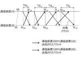
- FIG. 3 schematically shows a state in which packets are transmitted and received between the communication device 10 and the communication device 20 of the present embodiment.
- the delay time Td s of the target packet as a transmission packet an example of correcting will be described with reference to the minimum delay time Td rmin of the received packet.
- Td rmin the minimum delay time of the received packet.
- a configuration in which the delay time is corrected only for one target packet selected by the selection unit 104 will be described. For example, all the packets transmitted and received by the communication unit 102 are set as the target packets and the delay time is calculated. Correction may be made.
- the delay time acquisition unit 103 of the present embodiment acquires the delay time of the transmission packet transmitted by the communication unit 102 selected as the target packet.
- the delay time of the transmission packet is the time from the transmission time Ts 10 at which the communication device 10 transmits the transmission packet to the reception time Tr 20 at which the communication device 20 receives the transmission packet.
- the correction unit 105 reads out the minimum delay time Td rm in stored in the memory 106.
- Td r1 since Td r1 is the smallest among the delay times Td r1 to Td r3 , the delay time Td r1 is read out as the minimum delay time Td min.
- the correction unit 105 calculates the correction value a by setting the minimum delay time Td min as the correction value.
- the correction value a calculated by the present embodiment by substituting the equation 1, the correction delay time T s of the target packet can be determined by Equation 3 below.
- FIG. 4 shows a process of acquiring the delay time of the received packet, which is used to correct the delay time of the target packet.
- the communication unit 102 receives the received packet transmitted from the communication device 20.
- the time when the received packet is received in S101, that is, the reception time tr 10 is acquired.
- the transmission time ts 20 in which the received packet is transmitted from the communication device 20 included in the received packet is acquired.
- it acquires the time from the transmission time ts 20 until the reception time tr 10 as the delay time Td r.
- the storage time obtained delay Td r in the memory 106 is obtained.
- FIG. 5 shows a process of correcting the delay time of the target packet by using the minimum delay time having the minimum value among the delay times acquired by the process of FIG.
- the selection unit 104 selects the target packet for which the delay time is to be corrected.
- it reads the delay time Td s of the target packet selected in S201 from the memory 106, obtains.
- the minimum delay time Td min which is the minimum value among the delay times of the received packets acquired by the process shown in FIG. 4, is read from the memory 106 and acquired.
- the correction value a is calculated based on the minimum delay time Td min acquired in S203. In the present embodiment, the correction value a is calculated by setting the minimum delay time Td min read from the memory 106 as the correction value.
- S205 to correct the delay time Td s of the target packet by using the correction value a.
- the operation of the communication device 10 shown in FIGS. 4 and 5 not only shows a method of correcting the delay time in the communication device 10, but also shows a processing procedure of the delay time correction program executed by the communication device 10.
- the processing is not limited to the order shown in FIGS. 4 and 5. That is, the order may be changed as long as there is no restriction that the result of the previous step is used in a certain step.
- the above points are the same for the flowcharts of the second and subsequent embodiments.
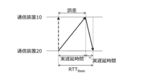
- FIG. 6 is a diagram for explaining the maximum error between the correction delay time T and the actual delay time according to the method of the present embodiment.
- the dashed arrow shown in FIG. 6 indicates a state in which the actual delay time for the minimum delay time Td rm in received packets is estimated to be 0.
- the solid line shows the actual actual delay time of the received packet and the transmitted packet.
- RTT Base the real delay time of the minimum delay time Td rmin of the received packet, the minimum delay time Td smin reference sum of real time delay for the RTT of the transmission packet (Round Trip Time) (hereinafter, RTT Base) If the , RTT Base is expressed by the following equation 4.
- tr 10 min and ts 20 min are the reception time and transmission time of the minimum delay time Td rmin of the received packet
- tr 20 min and ts 10 min are the reception time and transmission time of the minimum delay time Td smin of the transmission packet.
- the sum of the actual delay times of the received packet and the transmitted packet is equal to the sum of the delay times of the received packet and the transmitted packet acquired by the delay time acquisition unit 103.
- the correction value a is calculated by estimating that the actual delay time of the minimum delay time Td rm in the received packet is 0.
- the actual delay time of the minimum delay time Td rm in does not become zero.
- RTT Base the difference between the actual delay time estimated by the received packet and the actual delay time is the maximum.
- the delay time of the target packet can be corrected by using the information on the delay time of the received packet stored on the communication device 10 side that corrects the delay time, so that the communication device 10 can be corrected. It is possible to easily perform the correction processing of the delay time of the target packet in.
- the first embodiment is described assuming that the communication device 10 and the communication device 20 always communicate on the same communication path. However, packets transmitted and received between the communication device 10 and the communication device 20 are not always transferred by the same route. When the communication paths between the communication device 10 and the communication device 20 are different, the delay time generated in the packet is likely to be different for each communication path.
- the delay time acquisition unit 103 sets the delay time of the packet received using the first communication path and the second communication path. Acquire the delay time of each received packet. Then, the correction unit 105 has a delay time of the received packet transmitted from the communication device 20 using the first communication path and a delay time of the received packet transmitted from the communication device 20 using the second communication path. The delay time having the smallest value among them is read from the memory 106 as the minimum delay time. Then, the correction unit 105 calculates the correction value a based on the read minimum delay time.
- the correction value is based on the minimum delay time of the delay times of the received packets communicated using all the communication paths. Is calculated.
- the delay time generated in the packet may be different. Therefore, even when the protocols used for communication are different, it is desirable to calculate the correction value based on the minimum delay time of the delay times of the received packets communicated using each protocol.
- the configuration in which the communication device 10 and the communication device 20 communicate using a plurality of communication paths may be applied to the second to fifth embodiments described below.
- FIG. 7 schematically shows packets transmitted and received between the communication device 10 and the communication device 20 in the present embodiment.
- the delay time acquisition unit 103 of the present embodiment acquires the delay times Td s1 to Td s3 of the transmission packet shown in FIG. 7 in addition to the delay times Td r1 to Td r3 of the received packet shown in FIG.
- the correction unit 105 reads the minimum delay time from the memory 106, and estimates that this minimum delay time corresponds to the time difference r.
- the minimum delay time in the present embodiment is a delay time having the smallest value among the delay time of the received packet and the delay time of the transmitted packet.
- the communication apparatus 10 acquires the delay time Td s of the transmission packet transmitted.
- the delay time of the transmission packet is a communication device of the past transmission packet included in the reception packet, which acquires information indicating the delay time of the past transmission packet, or is included in the reception packet. It can be obtained from the information indicating the reception time in 20.
- S302 to store the delay time Td s of the transmission packet acquired in S301 in the memory.
- the delay time of the target packet can be corrected by using the processing flow shown in FIG.
- the downlink delay such as communication from the server device to the client device is shorter than the delay in the uplink direction such as communication from the client device to the server device. Therefore, when the communication device 10 is a server device and the communication device 20 is a client device, the delay time in the downlink direction of the packet transmitted by the communication device 10 is larger than the delay time in the uplink direction of the packet received by the communication device 10. It is more likely that it is smaller. Therefore, a more accurate correction value is calculated by calculating the correction value using the minimum value of the delay times of both the packets transmitted by the communication device 10 in addition to the packet received by the communication device 10. Is possible.
- the correction unit 105 corresponds to the minimum delay time Td rm in (corresponding to the “first minimum delay time”), which is the minimum value of the delay time (corresponding to the “first delay time”) from the transmission time to the reception time of the received packet. ) Is read from the memory 106.
- the delay time Td r1 is the minimum delay time Td rmin of the received packet.
- the correction unit 105 further increases the minimum delay time Td smin (“second minimum delay time”), which is the minimum value of the delay time (corresponding to the “second delay time”) from the transmission time to the reception time of the transmission packet. Corresponds to) is read from the memory 106.
- the delay time Td s2 is the minimum delay time Td smin of the transmitted packet.
- the real delay time of the minimum delay time Td rmin of the received packet if the estimated and the actual delay time of the minimum delay time Td smin transmission packet is equal to, the following Equation 5 is satisfied.
- tr 10 min and ts 20 min are the reception time and transmission time of the minimum delay time Td rmin of the received packet, and tr 20 min and ts 10 min are the reception time and transmission time of the minimum delay time Td smin of the transmission packet.
- the correction value a is expressed by the following formula 6.
- correction value a can be expressed as in the formula 7 by using the RTT Base described in the formula 4.
- the correction delay time T s of the target packet may be calculated using the following equation 8.
- the communication device 10 of the present embodiment performs the same operation as the series of processes shown in FIGS. 5 and 8.
- the correction value a is calculated based on the minimum delay time Td smin of the transmission packet and the minimum delay time Td rmin of the received packet. Specifically, the correction value a is calculated by calculating the formula 6 or the formula 7. Regardless of which of the formulas 6 and 7 is used, the correction value a of the present embodiment is a value obtained by halving the difference between the minimum delay time Td smin of the transmission packet and the minimum delay time Td rm in the received packet. Is the same as. Therefore, in S204, the correction value may be calculated using any of the formulas shown in Equations 6 and 7.
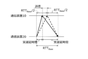
- FIG. 9 is a diagram illustrating an error between the corrected delay time and the actual delay time obtained by the present embodiment. Dashed line shown in FIG. 9 shows a real delay time of the minimum delay time Td rmin of the received packet, a state in which the actual delay time is estimated to be equal to the minimum delay time Td smin transmission packet. On the other hand, the solid line shows the actual actual delay time.
- the error between the estimated delay time and the actual actual delay time in this embodiment is the difference between the RTT Base / 2 and the actual delay time, and this error is the maximum RTT Base / 2.
- the delay time of packets transmitted and received between communication devices whose times are not synchronized can be estimated within the range of error RTT Base / 2.
- the total lower limit value (hereinafter, lower limit round-trip delay time) of the actual time from the transmission of the packet until the communication device 20 transmits the transmitted packet (corresponding to the "second actual delay time"), and At this time, the ratio of the actual delay time of the received packet and the transmitted packet (corresponding to the "delay time ratio”) may be a "known value". For example, these values may be preset for each communication device or communication network. When the lower limit round trip delay time and the delay time ratio are known values, the lower limit value of the delay time of each of the received packet and the transmitted packet can be obtained from these values.
- the correction value a is calculated by estimating that the difference from the time is equal.
- the "known value” includes not only the case where a predetermined value is set in advance but also the case where the communication device sets a predetermined value based on the past data.
- the correction unit 105 of the present embodiment reads from the memory 106 the lower limit round-trip delay time and the delay time ratio, which are known values, in addition to the minimum delay time Td min of the received packet. Then, the correction value a is calculated based on these values.
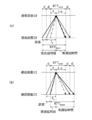
- FIG. 10 is a diagram illustrating the present embodiment.
- the alternate long and short dash line in FIG. 10 shows a packet having a lower limit round-trip delay time. Dashed line, the difference between the actual delay time of the lower limit value and the minimum delay time Td rmin of the delay time of the received packet, and, between the actual delay time of the minimum delay time Td smin the lower limit of the delay time of the transmission packet It shows the state in which the differences are estimated to be equal.
- the lower limit round-trip delay time is RTT limit
- the delay time ratio is (x: 1-x) (where x ⁇ 1-x)
- the actual delay time for the minimum delay time Td rm in the received packet and the transmitted packet.
- the sum of the minimum delay time Td smin and the actual delay time is expressed by RTT Base.
- the difference between the actual delay time with a lower limit value and the minimum delay time Td rmin of the delay time of the received packet, and the difference between the actual delay time of the lower limit value and the minimum delay time Td smin of the delay time of the transmission packet d is represented by the following equation 9.
- Equation 10 the value of the actual delay time is determined by Equation 10 below.
- the correction value a is the following formula Calculated using.
- the correction delay time of the target packet can be calculated by using the following formula 12.
- the communication device 10 of the present embodiment performs the same operation as the series of processes shown in FIGS. 5 and 8. However, in the present embodiment, in S204 of FIG. 5, the correction value a is calculated based on the known values of the lower limit round-trip delay time, the delay time ratio, and the minimum delay time Td rm in the received packet. Specifically, the correction value a is calculated by calculating the mathematical formula 11.
- Equation 12 While it is calculation formula in the case of using a minimum delay time Td rmin of the received packet, the delay time ratio (1-x: x) if (x ⁇ 1-x) of the correction delay time T Is expressed using Td smin.
- FIG. 11 is a diagram illustrating an error between the corrected delay time and the actual delay time obtained by the present embodiment. Similar to FIG. 10, the alternate long and short dash line in FIG. 11 shows the packet having the lower limit round-trip delay time, and the broken line shows the difference between the lower limit value of the delay time of the received packet and the actual delay time for the minimum delay time Td rm in. , The difference between the lower limit of the delay time of the transmitted packet and the actual delay time for the minimum delay time Td smin is estimated to be equal. The solid line shows the actual actual delay time.
- FIG. 11 (a) the actual value of the actual delay time of the received packet indicates a greater than the delay time T e calculated by the equation 10, the maximum error in this case becomes as d.
- FIG. 11 (b) the actual value of the actual delay time of the received packet indicates a smaller than the delay time T e calculated by the equation 10, the maximum error in this case is d. That is, an error of ⁇ d may occur in the correction value a obtained by the present embodiment. As a result, the maximum error of the delay time of the target packet corrected using the correction value a is d.
- the correction value is calculated using the minimum delay time, which is the minimum value among the delay times acquired within the predetermined period.
- the time difference r between the clock 101 and the clock 201 may change with the passage of time. In such a case, the accuracy of the correction value corresponding to the time difference r calculated using the first to fourth embodiments may decrease.
- a predetermined period is set according to the change over time of the time difference r, and the correction value is calculated using the minimum value of the delay times acquired within the predetermined period. Suppresses the accuracy of the correction value from decreasing.
- the correction unit 105 of the present embodiment calculates the correction value a based on the minimum delay time, which is the minimum value of the delay times acquired by the delay time acquisition unit 103 from the first time to the second time. ..
- the correction value a of the present embodiment may be calculated using any of the first to fourth embodiments.
- the first time and the second time are, for example, the difference between the time indicated by the clock 101 at the first time and the time indicated by the clock 201 (corresponding to the "first time difference”) and the clock 101 at the second time.
- the difference between the time indicated by the clock 201 and the time indicated by the clock 201 (corresponding to the “second time difference”), that is, the amount of change in the time difference r is set to be a preset threshold value “or less”.
- This threshold value is an allowable value of error, and may be set to, for example, the lower limit round-trip delay time RTT limit described in the fourth embodiment, the minimum value or the average value of the Ping values measured in the past, and the like.
- the amount of change in the time difference r can be obtained from the amount of change in the time difference r per unit time, and the amount of change in the time difference r per unit time can be obtained by measuring the time difference between the clock 101 and the clock 102 and the absolute time, or , Obtained from the performance of the crystal oscillator.
- FIG. 12 shows the communication system 2 according to the present embodiment.
- the communication device 11 includes a network determination unit 111 in addition to the configuration shown in FIG. Further, in the communication system 2 shown in FIG. 12, the communication device 11 uses the communication network 31 (corresponding to the “second communication network”) in addition to the communication network 30 (corresponding to the “first communication network”). Can communicate with the communication device 20.
- the communication device 11 uses the communication network 31 (corresponding to the “second communication network”) in addition to the communication network 30 (corresponding to the “first communication network”). Can communicate with the communication device 20.
- the correction unit 105 of the present embodiment corrects the delay time of the target packet by using any of the methods described in the first to fifth embodiments.
- the correction unit 105 of the present embodiment further sets the correction delay time, which is the minimum of the correction delay times of the packets received or transmitted using the first communication network 30, as the reference in the first communication network 30. It is stored in the memory 106 as a delay time (hereinafter, referred to as a first reference delay time).
- the first reference delay time is estimated to be a delay time in a state where the first communication network 30 is not loaded, that is, in a no-load state.
- the correction unit 105 sets the correction delay time, which is the minimum of the correction delay time of the packet received or transmitted using the second communication network 31, to the reference delay time in the second communication network 31 (hereinafter referred to as “reference delay time”). It is saved in the memory 106 as the second reference delay time). Similar to the first reference delay time, the second reference delay time is estimated to be the delay time when the second communication network 31 is in a no-load state.
- the network determination unit 111 determines the correction delay time of packets sent and received using the unknown communication network and the reference delay stored in the memory 106. Compare with time.
- the network determination unit 111 determines that the unknown communication network is the first communication network 30.
- the network determination unit 111 determines that the unknown communication network is the second communication network 31.
- the method for determining whether the correction delay time is closer to the first or second reference delay time is, for example, an arbitrary method such as an absolute value of the difference between the delay time and the reference delay time, past statistical results, and the like. May be used.
- FIG. 13 schematically shows the relationship between the delay time that can occur for each communication network and the occurrence rate thereof.
- the communication network in use can be determined by comparing the value of the correction delay time with the tendency of the communication delay time of each communication network.
- FIG. 13 is a diagram for explaining the tendency of the delay time for each communication network, and the WiFi, LTE, and 3G communication networks do not necessarily show the tendency of the delay time shown in the figure.
- the communication device 10 and the communication device 20 can communicate via the two communication networks 30 and 31 has been described as an example, but as a matter of course, the communication device communicates via an arbitrary number of communication networks. You may.
- the communication networks 30 and 31 used for transmitting and receiving packets may each be composed of a plurality of networks.
- the communication network may be composed of 3G and the Internet.
- the delay time of the Internet is usually LTE, except when the transmission distance is extremely long, the transmission path includes a radio section, and congestion occurs on the transmission path. It is known that it is extremely small compared to 3G and the like. Therefore, when the communication network is composed of 3G and the Internet, the influence of the delay time generated by the Internet is usually small, and the correction delay time of the target packet tends to be the same as the delay time of 3G.
- the communication device 11 When the communication device 11 is a device such as a router or a repeater, the communication device 11 may not have detailed information on the communication network in use. According to the present embodiment, even when the communication network in use is unknown in this way, it is possible to determine the communication network by using the delay time that is the reference of the communication network.
- the network determination unit 111 utilizes the reference delay time obtained by the method described above and the line speeds of the first or second communication networks 30 and 31, and uses the first or second communication network.
- the delay may be predicted and determined when a predetermined load is applied to the network.
- Equation 13 To predict the delay time T i which occurs when transmitting and receiving packets.
- Data in Q is the amount of data in the transmission waiting queue of the packet transmitted from the communication unit 102
- DN is the reference delay time
- S is the line speed.
- the delay time T that can occur when the amount of data to be sent to the queue waiting to be transmitted is adjusted by using Equation 13. i can be calculated.
- the network determination unit 111 describes an example of determining a communication network using the correction delay time obtained by using the method according to the first to fifth embodiments. However, the network determination unit 111 can also determine the communication network by using the delay time of the packet transmitted / received between the two communication devices whose time is synchronized.
- the part of the invention of the communication device is as follows.
- a communication device (11) that transmits / receives packets from another communication device via the first communication network (30) or the second communication network (31).
- a communication unit (102) that receives a first packet, which is the packet transmitted from the other communication device, and transmits a second packet, which is the packet transmitted to the other communication device.
- the own device reception time which is the time when the communication unit receives the first packet from the transmission time of the other device which is the time when the first packet is transmitted from the other communication device. From the first delay time, which is the time until, and the own device transmission time, which is the time when the communication unit transmits the second packet, to the time when the other communication device receives the second packet.
- a delay time acquisition unit (103) that acquires a second delay time, which is the time until the reception time of a certain other device, and The minimum value of the delay time of the packet transmitted / received via the first communication network is stored as the first reference delay time, and the delay time of the packet transmitted / received via the second communication network is stored.
- a memory (106) that stores the smallest value as the second reference delay time, and
- a selection unit (104) that selects one of the first packet or the second packet as a target packet, and The delay time of the target packet is compared with the first reference delay time and the second reference delay time, and the target packet is transmitted via either the first communication network or the second communication network.
- a network determination unit (111) that determines whether transmission / reception has been performed, and A communication device.
- the block diagram used in the explanation of the embodiment is a classification and arrangement of the configuration of the device for each function.
- the blocks showing each function are realized by any combination of hardware or software. Further, since the block diagram shows the function, the block diagram can be grasped as the disclosure of the invention of the method and the invention of the program that realizes the method.
- examples of the form of the communication device of the present invention include the following.
- Examples of the form of the component include a semiconductor element, an electronic circuit, a module, and a microcomputer.
- Examples of the semi-finished product include an electronic control unit (ECU) and a system board.
- Examples of finished products include mobile phones, smartphones, tablets, personal computers (PCs), workstations, servers, and routers.
- it includes a device having a communication function and the like, and examples thereof include a video camera, a still camera, and a car navigation system.
- the present invention can be realized not only by the dedicated hardware having the configuration and the function described in each embodiment, but also a program for realizing the present invention recorded on a recording medium such as a memory or a hard disk, and an executable program thereof. It can also be realized as a combination with a dedicated or general-purpose hardware having a general-purpose CPU and memory.
- Programs stored in a non-transitional substantive recording medium of dedicated or general-purpose hardware for example, an external storage device (hard disk, USB memory, CD / BD, etc.) or an internal storage device (RAM, ROM, etc.)
- a recording medium or via a communication line from a server without a recording medium This ensures that you always have the latest features through program upgrades.
- the communication device of the present disclosure can be applied to any communication device capable of transmitting and receiving packets to and from other communication devices.
Landscapes
- Engineering & Computer Science (AREA)
- Computer Networks & Wireless Communication (AREA)
- Signal Processing (AREA)
- Environmental & Geological Engineering (AREA)
- Health & Medical Sciences (AREA)
- Cardiology (AREA)
- General Health & Medical Sciences (AREA)
- Physics & Mathematics (AREA)
- General Physics & Mathematics (AREA)
- Synchronisation In Digital Transmission Systems (AREA)
- Data Exchanges In Wide-Area Networks (AREA)
Priority Applications (2)
| Application Number | Priority Date | Filing Date | Title |
|---|---|---|---|
| CN202080092626.3A CN114938705B (zh) | 2020-01-14 | 2020-10-19 | 通信装置、通信装置、存储介质以及延迟时间修正方法 |
| US17/861,804 US12192936B2 (en) | 2020-01-14 | 2022-07-11 | Communication device, method for communication device, and program product for communication device |
Applications Claiming Priority (2)
| Application Number | Priority Date | Filing Date | Title |
|---|---|---|---|
| JP2020-003656 | 2020-01-14 | ||
| JP2020003656A JP7173058B2 (ja) | 2020-01-14 | 2020-01-14 | 通信装置、及び通信装置に用いられるプログラム及び方法 |
Related Child Applications (1)
| Application Number | Title | Priority Date | Filing Date |
|---|---|---|---|
| US17/861,804 Continuation US12192936B2 (en) | 2020-01-14 | 2022-07-11 | Communication device, method for communication device, and program product for communication device |
Publications (1)
| Publication Number | Publication Date |
|---|---|
| WO2021145039A1 true WO2021145039A1 (ja) | 2021-07-22 |
Family
ID=76864113
Family Applications (1)
| Application Number | Title | Priority Date | Filing Date |
|---|---|---|---|
| PCT/JP2020/039283 Ceased WO2021145039A1 (ja) | 2020-01-14 | 2020-10-19 | 通信装置、及び通信装置に用いられるプログラム及び方法 |
Country Status (4)
| Country | Link |
|---|---|
| US (1) | US12192936B2 (https=) |
| JP (1) | JP7173058B2 (https=) |
| CN (1) | CN114938705B (https=) |
| WO (1) | WO2021145039A1 (https=) |
Families Citing this family (1)
| Publication number | Priority date | Publication date | Assignee | Title |
|---|---|---|---|---|
| CN120239090A (zh) * | 2023-12-28 | 2025-07-01 | 维沃移动通信有限公司 | 信号处理方法、时延基准点指示方法、装置及设备 |
Citations (3)
| Publication number | Priority date | Publication date | Assignee | Title |
|---|---|---|---|---|
| WO2014016993A1 (ja) * | 2012-07-27 | 2014-01-30 | 日本電気株式会社 | 通信装置、時刻同期システム及び時刻同期方法 |
| JP2014165582A (ja) * | 2013-02-22 | 2014-09-08 | Nippon Telegraph & Telephone East Corp | 時刻同期システム、時刻同期方法、スレーブノード及びコンピュータプログラム |
| JP2016025474A (ja) * | 2014-07-18 | 2016-02-08 | セイコーソリューションズ株式会社 | 遅延測定方法、遅延測定装置、及びプログラム |
Family Cites Families (19)
| Publication number | Priority date | Publication date | Assignee | Title |
|---|---|---|---|---|
| JP3480701B2 (ja) * | 1999-08-06 | 2003-12-22 | 日本電気株式会社 | パケットネットワーク伝送遅延測定方法およびプログラムを記録した機械読み取り可能な記録媒体 |
| JP4668158B2 (ja) * | 2006-11-01 | 2011-04-13 | エヌ・ティ・ティ・コムウェア株式会社 | 遅延測定システムおよび方法 |
| US20090003379A1 (en) * | 2007-06-27 | 2009-01-01 | Samsung Electronics Co., Ltd. | System and method for wireless communication of uncompressed media data having media data packet synchronization |
| US7844725B2 (en) * | 2008-07-28 | 2010-11-30 | Vantrix Corporation | Data streaming through time-varying transport media |
| JP5224996B2 (ja) | 2008-09-29 | 2013-07-03 | 京セラ株式会社 | 無線通信装置 |
| JP5369814B2 (ja) * | 2009-03-26 | 2013-12-18 | ソニー株式会社 | 受信装置および受信装置の時刻修正方法 |
| US8018972B2 (en) * | 2009-06-30 | 2011-09-13 | Alcatel Lucent | Timing over packet performance |
| JP5449566B2 (ja) * | 2010-09-15 | 2014-03-19 | 三菱電機株式会社 | 通信装置および遅延検出方法 |
| JP6203064B2 (ja) * | 2014-01-21 | 2017-09-27 | 株式会社東芝 | 時刻同期クライアント、システム、及びプログラム |
| JP2016034065A (ja) * | 2014-07-31 | 2016-03-10 | 株式会社日立製作所 | 制御装置及びネットワークシステム |
| DE102015200625A1 (de) * | 2015-01-16 | 2016-07-21 | Bayerische Motoren Werke Aktiengesellschaft | Einlegeelement für ein faserverstärktes Rohr |
| US10938585B2 (en) * | 2015-03-16 | 2021-03-02 | Qualcomm Incorporated | Location and range determination using broadcast messages |
| JP6569450B2 (ja) | 2015-10-08 | 2019-09-04 | 株式会社デンソー | 情報処理装置および情報処理システム |
| JP6536398B2 (ja) * | 2015-12-25 | 2019-07-03 | 株式会社デンソー | 無線通信システムおよび無線通信端末 |
| US10470156B2 (en) * | 2016-06-03 | 2019-11-05 | Locix, Inc. | Systems and methods for coarse and fine time of flight estimates for precise radio frequency localization in the presence of multiple communication paths |
| US11212227B2 (en) * | 2019-05-17 | 2021-12-28 | Pensando Systems, Inc. | Rate-optimized congestion management |
| US11329745B2 (en) * | 2019-08-22 | 2022-05-10 | Skylo Technologies, Inc. | Dynamically estimating a propagation time between a first node and a second node of a wireless network |
| US12069602B2 (en) * | 2019-08-22 | 2024-08-20 | Skylo Technologies, Inc. | Time delay estimations between wireless nodes |
| US11191053B1 (en) * | 2020-08-06 | 2021-11-30 | Facebook, Inc. | Network-based clock for time distribution across a wireless network |
-
2020
- 2020-01-14 JP JP2020003656A patent/JP7173058B2/ja active Active
- 2020-10-19 CN CN202080092626.3A patent/CN114938705B/zh active Active
- 2020-10-19 WO PCT/JP2020/039283 patent/WO2021145039A1/ja not_active Ceased
-
2022
- 2022-07-11 US US17/861,804 patent/US12192936B2/en active Active
Patent Citations (3)
| Publication number | Priority date | Publication date | Assignee | Title |
|---|---|---|---|---|
| WO2014016993A1 (ja) * | 2012-07-27 | 2014-01-30 | 日本電気株式会社 | 通信装置、時刻同期システム及び時刻同期方法 |
| JP2014165582A (ja) * | 2013-02-22 | 2014-09-08 | Nippon Telegraph & Telephone East Corp | 時刻同期システム、時刻同期方法、スレーブノード及びコンピュータプログラム |
| JP2016025474A (ja) * | 2014-07-18 | 2016-02-08 | セイコーソリューションズ株式会社 | 遅延測定方法、遅延測定装置、及びプログラム |
Also Published As
| Publication number | Publication date |
|---|---|
| US20220353053A1 (en) | 2022-11-03 |
| CN114938705A (zh) | 2022-08-23 |
| CN114938705B (zh) | 2024-07-09 |
| US12192936B2 (en) | 2025-01-07 |
| JP7173058B2 (ja) | 2022-11-16 |
| JP2021111898A (ja) | 2021-08-02 |
Similar Documents
| Publication | Publication Date | Title |
|---|---|---|
| US9030959B2 (en) | Apparatus and method for monitoring quality metrics associated with a wireless network | |
| US8976656B2 (en) | Available bandwidth measurement system, transmission device, available bandwidth measurement method and recording medium | |
| KR20150113000A (ko) | 와이파이 레인징을 위한 주파수 오프셋 보상 | |
| US11412403B2 (en) | Benchmarking of delay estimates in a 5G network for quality of service flow setup and monitoring | |
| CN108934034A (zh) | 一种发送和接收数据包的方法、设备及系统 | |
| CN115002008B (zh) | 一种网络时延测量的方法、装置、设备以及存储介质 | |
| US20160109554A1 (en) | ADAPTIVE OPTIMIZATION OF TIME OF FLIGHT (ToF) EXCHANGE | |
| US8879403B2 (en) | Link microbenchmarking with idle link correction | |
| US20170280342A1 (en) | Measurement apparatus, measurement method, and communication system | |
| US9331803B2 (en) | System and method of synchronization among a control apparatus and a plurality of terminals | |
| WO2017012337A1 (zh) | 上行链路时间调整方法及装置 | |
| WO2021145039A1 (ja) | 通信装置、及び通信装置に用いられるプログラム及び方法 | |
| US8989039B2 (en) | Packet transfer delay measurement system | |
| US8289868B2 (en) | Network device and method of measuring upstream bandwidth employed thereby | |
| JP6355116B2 (ja) | パケットロス検出のための方法、装置、およびシステム | |
| US11627063B1 (en) | Systems and methods for measuring unidirectional latency of applications over asymmetric links | |
| CN103716357B (zh) | 一种移动信息同步方法、装置及移动通信终端 | |
| WO2018214610A1 (zh) | 一种发送和接收数据包的方法、设备及系统 | |
| KR101488133B1 (ko) | 단말을 위한 에너지 효율적인 가용대역폭 측정 방법 및 장치 | |
| KR20130091467A (ko) | 서버에서 발송하는 udp 패킷을 이용한 클라이언트 단말에서의 트래픽 지연 시간 측정 방법 | |
| CN114629826A (zh) | 一种网络最大带宽估计方法、装置、电子设备及存储介质 | |
| JP4678046B2 (ja) | 通信装置、通信システム、遅延時間の測定時間設定方法、遅延時間算出方法およびプログラム | |
| US12284100B2 (en) | Network delay estimation | |
| WO2025217802A1 (en) | Pdu set monitoring | |
| WO2019062525A1 (zh) | 上行载波聚合维护方法、系统、装置及可读存储介质 |
Legal Events
| Date | Code | Title | Description |
|---|---|---|---|
| 121 | Ep: the epo has been informed by wipo that ep was designated in this application |
Ref document number: 20913648 Country of ref document: EP Kind code of ref document: A1 |
|
| NENP | Non-entry into the national phase |
Ref country code: DE |
|
| 122 | Ep: pct application non-entry in european phase |
Ref document number: 20913648 Country of ref document: EP Kind code of ref document: A1 |