WO2021144903A1 - Dna検出方法およびdna検出システム - Google Patents
Dna検出方法およびdna検出システム Download PDFInfo
- Publication number
- WO2021144903A1 WO2021144903A1 PCT/JP2020/001171 JP2020001171W WO2021144903A1 WO 2021144903 A1 WO2021144903 A1 WO 2021144903A1 JP 2020001171 W JP2020001171 W JP 2020001171W WO 2021144903 A1 WO2021144903 A1 WO 2021144903A1
- Authority
- WO
- WIPO (PCT)
- Prior art keywords
- dna
- compartments
- gene
- melting temperature
- pseudogene
- Prior art date
- Legal status (The legal status is an assumption and is not a legal conclusion. Google has not performed a legal analysis and makes no representation as to the accuracy of the status listed.)
- Ceased
Links
Images


Classifications
-
- C—CHEMISTRY; METALLURGY
- C12—BIOCHEMISTRY; BEER; SPIRITS; WINE; VINEGAR; MICROBIOLOGY; ENZYMOLOGY; MUTATION OR GENETIC ENGINEERING
- C12Q—MEASURING OR TESTING PROCESSES INVOLVING ENZYMES, NUCLEIC ACIDS OR MICROORGANISMS; COMPOSITIONS OR TEST PAPERS THEREFOR; PROCESSES OF PREPARING SUCH COMPOSITIONS; CONDITION-RESPONSIVE CONTROL IN MICROBIOLOGICAL OR ENZYMOLOGICAL PROCESSES
- C12Q1/00—Measuring or testing processes involving enzymes, nucleic acids or microorganisms; Compositions therefor; Processes of preparing such compositions
- C12Q1/68—Measuring or testing processes involving enzymes, nucleic acids or microorganisms; Compositions therefor; Processes of preparing such compositions involving nucleic acids
- C12Q1/6813—Hybridisation assays
- C12Q1/6816—Hybridisation assays characterised by the detection means
-
- C—CHEMISTRY; METALLURGY
- C12—BIOCHEMISTRY; BEER; SPIRITS; WINE; VINEGAR; MICROBIOLOGY; ENZYMOLOGY; MUTATION OR GENETIC ENGINEERING
- C12Q—MEASURING OR TESTING PROCESSES INVOLVING ENZYMES, NUCLEIC ACIDS OR MICROORGANISMS; COMPOSITIONS OR TEST PAPERS THEREFOR; PROCESSES OF PREPARING SUCH COMPOSITIONS; CONDITION-RESPONSIVE CONTROL IN MICROBIOLOGICAL OR ENZYMOLOGICAL PROCESSES
- C12Q1/00—Measuring or testing processes involving enzymes, nucleic acids or microorganisms; Compositions therefor; Processes of preparing such compositions
- C12Q1/68—Measuring or testing processes involving enzymes, nucleic acids or microorganisms; Compositions therefor; Processes of preparing such compositions involving nucleic acids
- C12Q1/6813—Hybridisation assays
- C12Q1/6834—Enzymatic or biochemical coupling of nucleic acids to a solid phase
- C12Q1/6837—Enzymatic or biochemical coupling of nucleic acids to a solid phase using probe arrays or probe chips
-
- C—CHEMISTRY; METALLURGY
- C12—BIOCHEMISTRY; BEER; SPIRITS; WINE; VINEGAR; MICROBIOLOGY; ENZYMOLOGY; MUTATION OR GENETIC ENGINEERING
- C12Q—MEASURING OR TESTING PROCESSES INVOLVING ENZYMES, NUCLEIC ACIDS OR MICROORGANISMS; COMPOSITIONS OR TEST PAPERS THEREFOR; PROCESSES OF PREPARING SUCH COMPOSITIONS; CONDITION-RESPONSIVE CONTROL IN MICROBIOLOGICAL OR ENZYMOLOGICAL PROCESSES
- C12Q1/00—Measuring or testing processes involving enzymes, nucleic acids or microorganisms; Compositions therefor; Processes of preparing such compositions
- C12Q1/68—Measuring or testing processes involving enzymes, nucleic acids or microorganisms; Compositions therefor; Processes of preparing such compositions involving nucleic acids
- C12Q1/6844—Nucleic acid amplification reactions
- C12Q1/6851—Quantitative amplification
-
- C—CHEMISTRY; METALLURGY
- C12—BIOCHEMISTRY; BEER; SPIRITS; WINE; VINEGAR; MICROBIOLOGY; ENZYMOLOGY; MUTATION OR GENETIC ENGINEERING
- C12Q—MEASURING OR TESTING PROCESSES INVOLVING ENZYMES, NUCLEIC ACIDS OR MICROORGANISMS; COMPOSITIONS OR TEST PAPERS THEREFOR; PROCESSES OF PREPARING SUCH COMPOSITIONS; CONDITION-RESPONSIVE CONTROL IN MICROBIOLOGICAL OR ENZYMOLOGICAL PROCESSES
- C12Q1/00—Measuring or testing processes involving enzymes, nucleic acids or microorganisms; Compositions therefor; Processes of preparing such compositions
- C12Q1/68—Measuring or testing processes involving enzymes, nucleic acids or microorganisms; Compositions therefor; Processes of preparing such compositions involving nucleic acids
- C12Q1/6844—Nucleic acid amplification reactions
- C12Q1/686—Polymerase chain reaction [PCR]
Definitions
- the present invention relates to a DNA detection method and a DNA detection system, and particularly to digital PCR.
- Non-Patent Document 1 Conventional genetic tests include methods such as PCR (Patent Document 2-4) and real-time PCR (Non-Patent Document 1). These methods have a problem that the measurement reproducibility is lowered when the amount of the gene to be detected (referred to as “target gene” in the present specification) is very small.
- Digital PCR (Patent Document 1) was developed as a method to solve this problem.
- a trace amount of DNA can be quantified by determining DNA as 0 (none) or 1 (presence) using a critically diluted sample and detecting it.
- a DNA polymerase, a primer, and a fluorescently labeled probe necessary for PCR are added to the critically diluted sample to prepare a PCR reaction solution. Divide the PCR reaction into microsections such as wells or droplets. At this time, each compartment is made to either contain or not contain one molecule of the target gene.
- the target gene in the microcompartment is amplified by PCR.
- the target gene can be quantified by measuring the fluorescence intensity of each micro-compartment after PCR and counting the number of micro-compartments having a fluorescence intensity exceeding the threshold value.
- the present inventors measure the melting temperature (Tm) of the PCR amplification product even if the PCR reaction efficiency of each microsection is non-uniform.
- Patent Document 5 has developed a technique capable of discriminating the target gene in a microcompartment. Specifically, for example, after PCR, by measuring the melting temperature (Tm) at which the target gene amplified in the microsection and the fluorescently labeled probe dissociate, the melting temperature is measured even if the reaction efficiency of PCR is non-uniform. It became possible to identify the genotype of the target gene by the difference in the above.
- pseudogene may be a problem in the detection of the target gene.
- pseudogenes that have lost their functions are also born.
- Pseudogene is a gene that makes a copy in the process of evolution, one that retains its original function while the other changes, and the altered gene loses its function without acquiring a new function. Therefore, the sequences of both are extremely homologous, such as the KRAS gene and its pseudogene, the KRASP1 gene.
- the target gene has a pseudogene
- the target gene and the pseudogene cannot be distinguished, and the pseudogene is erroneously counted as the target gene, and the number of copies of the target gene becomes larger than the true value.
- the target gene and pseudogene exist in the same compartment, so if a primer is designed by selecting a portion where the sequences of the target gene and pseudogene do not match even with only a few bases, the target gene and the target gene can be used. Pseudogene amplification competes, pseudogene amplification is suppressed, and the target gene can be preferentially amplified.
- the reaction solution to which the sample is added is divided into minute compartments so that one compartment contains or does not contain one molecule of the target gene. Therefore, only one of the target gene and the pseudogene is present in one compartment.
- Distinguishing between the target gene and the pseudogene is important for reducing false positives and false negatives and improving measurement reproducibility and measurement accuracy.
- an object of the present invention is to accurately distinguish between a microcompartment in which a target gene is arranged and a microcompartment in which a pseudogene is arranged by a measuring device in digital PCR using melting curve analysis, and accurately count the target gene.
- the present inventors can discriminate between the target gene and the pseudogene as different genes by designing the probe so that the melting temperature of the target gene and the pseudogene are different. Furthermore, it was found that they can be determined to be the target gene and its pseudogene from the correspondence between the count numbers of the two genes, and the present invention has been completed.
- the DNA solution may contain a plurality of types of DNA containing a first gene and its pseudogene, and the DNA solution may contain a fluorescently labeled probe or DNA.
- An example of the DNA detection system is An imaging device that captures an image of a device capable of placing a DNA solution in each of a plurality of compartments, wherein the DNA solution may contain a plurality of types of DNA including the first gene and its pseudogene.
- the DNA solution contains a fluorescently labeled probe or DNA intercalator, with an imaging device, A temperature control unit that changes the temperature of each of the compartments in order to carry out a nucleic acid amplification reaction in each of the compartments.
- a database for storing information representing a reference melting temperature for each of the first gene and the pseudogene of the first gene, and An image pickup control unit that causes the image pickup apparatus to take an image in order to acquire the fluorescence intensity that changes with a temperature change for each of the sections.
- a melting temperature memory that stores information representing the melting temperature of the double strand of the DNA arranged in the compartment, wherein the melting temperature is a temperature change in an image captured by the imaging apparatus. Melting temperature memory obtained based on the change in fluorescence intensity that accompanies
- the analysis unit is an analysis unit that counts the number of compartments in which the first gene is arranged and the number of compartments in which the pseudogene is arranged by using the database and the melting temperature memory.
- An analysis unit that outputs the number of compartments counted for each type of DNA and discriminates the first gene and the pseudogene from the melting temperature and the number of compartments counted. To be equipped.
- a microcompartment in which a target gene is arranged and a microcompartment in which a pseudogene is arranged can be more accurately distinguished by a measuring device, and the target gene can be counted more accurately.
- New DNA detection methods and DNA detection systems are provided.
- FIG. 6 is a schematic diagram showing a method of measuring the melting temperature of DNA using a fluorescently labeled probe in the DNA detection method of the first embodiment.
- FIG. 5 is a flowchart showing an embodiment of a method of measuring a melting temperature using the devices of FIGS. 3 and 4. An example of the measurement result displayed on the monitor. An example of the measurement result according to the first embodiment.
- FIG. 1 shows an example of measurement results based on the principle of the DNA detection method according to the first embodiment.
- the wild type of the target gene, the mutant type of the target gene, and the pseudo of the target gene are calculated by calculating the melting temperature of the DNA double strand based on the change in fluorescence intensity accompanying the temperature change. It is envisioned in a typical embodiment of the method of detecting a gene.
- the relationship between fluorescence intensity and melting temperature is plotted for the microcompartment 101 containing the wild-type allele of the target gene, the microcompartment 102 containing the mutant allele of the target gene, and the microcompartment 103 containing the pseudogene of the target gene. ing.
- FIG. 2 shows an example of the measurement result of digital PCR that detects the wild type and the mutant type of the target gene by measuring the fluorescence intensity of two different fluorescent dyes.
- FIG. 2 schematically shows the results when a yellow fluorescent-labeled probe was used for the wild-type allele of the target gene and a green fluorescent-labeled probe was used for the mutant allele of the target gene. It is a figure.
- the fluorescently labeled probe is complementary to the sequence located between the primer pairs used in PCR, and is configured such that when the primers are extended, the probe is degraded and the fluorescent label fluoresces. It is assumed that it has been done. Specifically, a TaqMan® probe can be exemplified.
- the yellow fluorescently labeled probe corresponding to the wild-type allele of the target gene is degraded in the microcompartment 201 containing the wild-type allele of the target gene, and emits yellow fluorescence. Further, in the micro-compartment 202 containing the mutant allele of the target gene, the green fluorescently labeled probe corresponding to the mutant A allele of the target gene is degraded to emit green fluorescence. Empty droplets that do not contain the gene of interest do not detect either green or yellow fluorescence (not shown).
- the target gene may have a pseudogene with a similar sequence. Even if there are several bases in the pseudogene that do not match the primer region designed for the target gene, the pseudogene is amplified in the microsection 203 containing the pseudogene because there is no competition with the target gene. As a result, the fluorescently labeled probe of the target gene is degraded and emits yellow fluorescence, and the distribution may overlap with the microsection 201 containing the wild-type allele of the target gene.
- genotype can be discriminated by utilizing the fact that the melting temperature of the fluorescently labeled probe and DNA differs depending on the genotype.
- FIG. 1 is a diagram schematically showing the results of measuring the melting temperature of DNA in each microsection using fluorescently labeled probes corresponding to each of wild type, mutant type, and pseudogene for the target gene. Is.
- a well-known molecular beacon can be used as the fluorescently labeled probe.
- the DNA detection method will be described in detail using the molecular beacon as an example.
- Molecular beacons are configured as oligonucleotides and have sequences complementary to the sequences between the primer pairs used in PCR to amplify the gene of interest. Further, the molecular beacon has sequences complementary to each other at both ends thereof, and a fluorescent dye is provided at one end and a quencher dye (quencher) is provided at the other end.
- the fluorescent dye and quenching dye at both ends separate and emit fluorescence, but when dissociated from the target gene as the temperature rises, the complementary sequences at both ends hybridize with each other.
- the stem loop structure is formed, and the fluorescent dye and the quenching dye come close to each other to quench the fluorescent dye.
- the fluorescent-labeled probe corresponding to the wild-type allele of the target gene hybridized with the DNA amplified by PCR to emit fluorescence, and corresponded to the fluorescent-labeled probe of the wild-type allele.
- the melting temperature is observed.
- the fluorescently labeled probe corresponding to the mutant allele of the target gene hybridizes with the DNA amplified by PCR to emit fluorescence, and becomes a fluorescently labeled probe of the mutant allele. The corresponding melting temperature is observed.
- a fluorescently labeled probe corresponding to the wild-type allele of the target gene hybridizes to the DNA amplified by PCR in a form containing a mismatched base to emit fluorescence, and this mismatch high A melting temperature corresponding to hybridization is observed.
- the presence or absence of a target gene having a wild-type allele, the presence or absence of a target gene having a mutant allele, and the presence or absence of a target gene having a pseudogene are determined. I can judge.
- the genotype of DNA in a microsection can be discriminated with high accuracy.
- the arrangement of the fluorescently labeled probe is determined so that the melting temperature (Tm) of each fluorescently labeled probe for the target gene is different, and the change in fluorescence intensity with temperature change is measured for the DNA in the microsection, and the melting curve is obtained.
- the relationship (eg ratio) between the copy number of the target gene and the copy number of the pseudogene is determined by the position of each gene on the chromosome, for example, if both are present on the autosomal chromosome, those The copy numbers are equal to each other. Therefore, the genotype of the DNA of each microsection is counted, and the relationship between the total number of wild-type and mutant copies of the target gene and the number of copies of the pseudogene is an expected relationship (for example, 1: 1). By confirming whether or not it conforms to 1), more accurate gene detection becomes possible.
- the DNA detection system includes a DNA detection device for detecting a target gene in a DNA solution, and executes the DNA detection method described in the present specification.
- the DNA detection device independently constitutes the DNA detection system, but it is also possible to design so that a plurality of devices cooperate to form the DNA detection system.
- the DNA detection device includes a temperature control unit for heating the DNA solution, a fluorescence measurement unit for measuring the intensity of fluorescence emitted from the DNA solution, and a change in the intensity of the fluorescence due to a temperature change of the DNA solution. It is provided with a computer that calculates the melting temperature of the DNA duplex based on the melting curve representing the above, and a monitor that displays information transmitted from the computer.
- the DNA solution may be on any carrier, for example, it may be provided as a droplet in oil, or it may be placed in a well such as a plate.
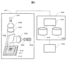
- FIGS. 3 and 4 are used to show a DNA detection device having a fluorescence measuring unit.
- FIG. 3 is a schematic diagram of the fluorescence measurement unit according to the first embodiment
- FIG. 4 is a schematic diagram of the digital PCR system according to the first embodiment.
- the fluorescence measuring unit of FIG. 3 measures the color and fluorescence intensity of the fluorescent dye contained in the critically diluted droplet or well.
- the digital PCR system of FIG. 4 includes a fluorescence measuring unit illustrated in FIG. 3, a computer for analyzing measurement data, and a monitor for displaying the results, and uses melting curve analysis.
- the fluorescence measuring unit measures the color and fluorescence intensity of the fluorescent dye contained in the DNA solution in the droplet or well, but the configuration of the DNA detection device according to the present invention is not limited thereto.
- the fluorescence intensity of the droplet is measured using a microchannel.
- the droplet 301 is flowing in the microchannel 303 in the direction of the arrow.
- the light source 304 irradiates the droplet with excitation light while the temperature adjusting unit (not shown) warms the droplet.
- the fluorescent substance contained in the droplet is excited by the light source 304, and the emitted fluorescence is detected by the photo multiple meter 306 through the fluorescent filter 305.
- the photo multiple meter 306 is an example of an imaging device that captures an image of a device capable of arranging a DNA solution in each of a plurality of compartments.
- the fluorescence measurement unit includes a light source 304, a fluorescence filter 305, and a photo multiple meter 306.
- the fluorescence measurement unit may be provided separately for each color of the fluorescent dye, or as shown in FIG. 3A, two types of fluorescent dyes are excited by the excitation light of one light source, and the respective fluorescence is emitted by the two fluorescent filters. It may be configured to detect at the same time.
- the droplets may be arranged on a plane as shown in FIGS. 3B and 3C, and the color and fluorescence intensity of the fluorescent dye of each droplet may be measured.
- a plurality of droplets 311 are arranged in an array on the droplet detection cartridge 310 and set on the temperature control stage 312 which is a temperature adjusting unit.
- the temperature control stage 312 changes the temperature of each compartment in order to carry out a nucleic acid amplification reaction in each compartment.
- the temperature of the droplet detection cartridge is changed in the temperature control stage 312, and the change in fluorescence intensity of the droplet due to the temperature change is measured.
- the fluorescence intensity changes differently between the droplet 301 containing the target gene and the droplet 302 not containing the target gene.
- the measurement procedure is as follows, for example. First, the excitation light is irradiated to each droplet 311 from the light source 304 through the lens 308, the fluorescence filter 305 and the dichroic mirror 309. The fluorescent substance contained in each droplet 311 is excited by the excitation light, and the emitted fluorescence is detected by the CCD camera 307 through the dichroic mirror 309, the fluorescent filter 305, and the lens 308.
- the CCD camera 307 is an example of an imaging device.
- FIG. 3A it is necessary to process the droplets one by one, but the devices of FIGS. 3B and C are preferable in that a large number of droplets can be processed at one time. Further, the devices of FIGS. 3B and 3C are more preferable than those of FIG. 3A in that the temperature control stage 312 can also be used for the DNA amplification reaction.
- wells arranged in an array may be used instead of the droplets. Specimens are added so that 1 or 0 target genes are contained in 1 well, and PCR is performed in the wells to measure the color and fluorescence intensity of the fluorescent dye in the wells.
- the reaction solution containing the sample is added to the wells provided in the well method detection cartridge 313. Then, PCR is performed in the well and set on the temperature control stage 312 which is a temperature control unit. The temperature of the cartridge 313 is changed by the temperature control stage 312, and the change in fluorescence intensity of the well accompanying the temperature change is measured. The fluorescence intensity changes differently between the well 314 containing the target gene and the well 315 not containing the target gene.
- each well is irradiated with excitation light from the light source 304 through the lens 308, the fluorescence filter 305 and the dichroic mirror 309.
- the fluorescent substance contained in the reaction solution in the well is excited by the excitation light, and the emitted fluorescence is detected by the CCD camera 307 through the dichroic mirror 309, the fluorescent filter 305, and the lens 308.
- PCR to melting curve analysis can be performed in the cartridge 313 without the step of arranging the droplets on the droplet detection cartridge.
- an inclination adjusting unit (not shown) may be provided under the temperature control stage 312.
- the inclination adjusting unit removes air bubbles generated in the cartridge 313 by heating by the temperature control stage 312. This prevents the fluorescence image from being unable to be acquired due to air bubbles when the fluorescence intensity of each well is subsequently measured while lowering the temperature of the sample by the temperature control stage 312.
- the fluorescence data detected by the fluorescence measurement unit 401 is sent to the computer 402.
- the analysis unit 403 calculates the melting temperature of the amplified product and stores it in the memory 405.
- the memory 405 functions as a melting temperature memory, and for each compartment, stores information representing the melting temperature of the double strand of DNA arranged in the compartment.
- the melting temperature is obtained based on the change in fluorescence intensity accompanying the temperature change in the image captured by the image pickup device (for example, the photo multiple meter 306).
- the relationship between gene type, melting temperature, and number is prepared in database 404 in advance.
- the database 404 stores information representing a reference predetermined melting temperature (reference melting temperature) for each of the target gene (first gene) and the pseudogene of the target gene.
- the genotype of the target gene is determined based on the measured value of the melting temperature of the memory 405, and the genotype is counted for each genotype.
- the count result is displayed on monitor 406.
- the monitor 406 is an example of an output device, and the display processing in the monitor 406 may be replaced with the output processing to another output device (printing device, non-volatile storage device, etc.).
- the DNA detection device may include a sample dividing portion.
- the sample division section divides the DNA solution containing the target gene into microsections.
- the micro-compartments may be configured as wells arranged in an array in the cartridge or as droplets dispersed in the oil. By constructing the compartment in this way, the limit dilution can be appropriately performed.
- the DNA detection device may include an amplification unit for amplifying DNA in a minute section.
- FIG. 5 shows an example of a database that stores information representing a reference melting temperature of a gene, which is prepared prior to digital PCR measurement.
- the data shown in FIG. 5 can be measured in advance by a pilot experiment or the like and stored in the database 404.
- the reference melting temperature is stored for each of the gene and the pseudogene of the gene. Also, in this example, the reference melting temperature is stored for each genotype. Multiple variants may be defined for one gene.
- the information representing the reference melting temperature is defined as a value representing a single temperature in this example, but may be defined as information representing a temperature range.
- information indicating the color of the fluorescent dye is stored for each genotype of each gene.
- each gene information indicating the relationship between the number of target genes (without distinguishing genotypes) and the number of pseudogenes is stored. This relationship is expressed, for example, as a ratio.
- a ratio In the example of FIG. 5, for gene A, it is shown that x copies of pseudogenes are present when x copies of the target gene are present, that is, the ratio of the number of pseudogenes to the number of target genes is 1. Is shown.
- the relationship between the target gene and the number of copies of the pseudogene is determined by the position on each chromosome, the relationship between the number of copies may be defined for each positional relationship on the chromosome. A specific example is shown below.
- the target gene is on the autosomal chromosome.
- the number of pseudogenes is equal to the number of the target gene (gene A in FIG. 5 may correspond to this case).
- the number of Pseudogenes is equal to the number of target genes in the female sample, while the number of Pseudogenes is half the number of target genes in the male sample ( Gene B in FIG. 5 corresponds to this case).
- the pseudogene is on the Y chromosome, the number of pseudogenes will be 0 for female specimens, and the number of pseudogenes for male specimens will be half the number of target genes.
- the target gene is on the X chromosome.
- the number of pseudogenes is equal to the number of target genes in the female sample, while the number of pseudogenes is twice the number of target genes in the male sample. become.
- the pseudogene is on the X chromosome, the number of pseudogenes is equal to the number of genes of interest (gene A in FIG. 5 may fall into this case).
- the pseudogene is on the Y chromosome, the number of pseudogenes is 0 in the case of a female sample, and the number of pseudogenes is equal to the number of target genes in the case of a male sample.
- the target gene is on the Y chromosome.
- the number of target genes is 0 in the case of a female sample.
- the pseudogene is on the autosomal chromosome, the number of pseudogenes is twice the number of the target gene.
- the pseudogene is on the X chromosome, the number of pseudogenes is equal to the number of genes of interest.
- the pseudogene is on the Y chromosome, the number of pseudogenes will be equal to the gene of interest.
- FIG. 6 is a schematic diagram showing the principle that the melting temperature of the target gene and the pseudogene can be measured using a fluorescently labeled probe.
- a fluorescently labeled probe it is preferable to use a molecular beacon designed to have a structure capable of hybridizing to the target gene.
- the fluorescently labeled probe 602 When the fluorescently labeled probe 602 is present alone as shown in FIG. 6A, a stem loop is formed and the fluorescent dye 603 and the quencher 604 are in close proximity to each other, so that fluorescence is not emitted.
- the loop portion of the fluorescently labeled probe 602 is annealed to the amplified DNA 601 in the sample solution at a temperature of about room temperature as shown in FIG. 6B.
- the fluorescent dye 603 and the quencher 604 are separated from each other, so that the fluorescently labeled probe 602 emits strong fluorescence.
- FIG. 6D shows an example of the result of plotting the melting curve (curve showing the change in fluorescence intensity with respect to temperature change) at this time on a graph.
- This fluorescently labeled probe may be shared with the fluorescently labeled probe for PCR, but a probe different from the fluorescently labeled probe for PCR may be prepared and used.
- the melting curve may be measured in parallel with the nucleic acid amplification reaction, or may be performed by raising the temperature of the sample solution independently of the nucleic acid amplification reaction (for example, after the nucleic acid amplification reaction is completed).
- the differential curve of the result of differentiating the fluorescence intensity with temperature is shown in FIG. 6E.
- the reference numerals are inverted.
- the temperature corresponding to the inflection point of the fluorescence intensity is calculated as the melting temperature 605 of the DNA double strand.
- the temperature at the inflection point of the fluorescence intensity in FIG. 6D corresponds to the temperature at the maximum value of the differential curve in FIG. 6E.
- the melting temperature can be calculated as an inflection point of fluorescence intensity. According to such a calculation method, the melting temperature can be calculated accurately.
- the melting temperature of the fluorescently labeled probe for detecting the target gene can be controlled based on a known technique. For example, it can be controlled by changing the probe sequence or chain length. Alternatively, it can be controlled by using an artificial DNA such as Peptide Nucleic Acid (PNA) or Locked Nucleic Acid (LNA).
- PNA Peptide Nucleic Acid
- LNA Locked Nucleic Acid
- the combination of the fluorescent dye 603 and the quencher 604 is not particularly limited as long as it is a combination generally used for real-time PCR.
- examples of the fluorescent dye 603 include FAM, VIC, ROX, Cy3, Cy5, and examples of the quencher 604 include TAMRA, BHQ1, BHQ2, and BHQ3.
- the sequence of the fluorescently labeled probe 602 may be prepared specifically for each of the wild type of the target gene, the mutant type of the target gene, and the pseudogene of the target gene, and these may be detected individually.
- the fluorescently labeled probe 602 includes a first fluorescently labeled probe having a sequence corresponding to the target gene and a second fluorescently labeled probe having a sequence corresponding to the pseudogene. be able to. With such a configuration, the target gene and the pseudogene can be more easily distinguished.
- the fluorescently labeled probe 602 includes a first fluorescently labeled probe having a sequence corresponding to the target gene.
- a DNA intercalator can be used instead of the fluorescently labeled probe.
- a DNA intercalator is added to a PCR reaction solution to prepare a sample solution, and a nucleic acid amplification reaction such as PCR is performed. At a temperature of about room temperature, the DNA intercalator binds to the double-stranded DNA amplified in the sample solution and emits strong fluorescence.
- the change in fluorescence intensity with respect to the temperature change may be measured by raising the temperature of the sample solution independently of the nucleic acid amplification reaction (for example, after the nucleic acid amplification reaction is completed).
- the melting temperature of the target gene can be controlled depending on the sequence of the PCR amplification product and the chain length of the sequence by changing the design of the primer.
- an intercalator that can be used for detecting double-stranded DNA whose fluorescence intensity increases by binding to double-stranded DNA is used.
- SYBR registered trademark
- Green I Green I
- SYBR Gold PicoGreen
- SYTO registered trademark
- Blue SYTO Green
- SYTO Orange SYTO Red
- POPO registered trademark
- BOBO registered trademark
- YOYO registered trademark
- TOTO registered trademark
- JOJO registered trademark
- POPO-3 LOLO (registered trademark) -1, BOBO-3, YOYO-3, TOTO- 3.
- PO-Pro (registered trademark) -1, YO-Pro (registered trademark) -1, TO-Pro (registered trademark) -1, JO-Pro (registered trademark) -1, PO-Pro-3, YO- Pro-3, TO-Pro-3, TO-Pro-5, ethidium bromide, etc. can be applied. If the DNA intercalator is heat resistant, it can be added to the wells or droplets prior to the PCR reaction.
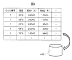
- FIG. 7 shows an example of data stored in the memory in the first embodiment. This data is obtained, for example, by analyzing the fluorescence intensity of the fluorescent dye due to the temperature change in the analysis unit for each well.
- the fluorescence intensity is measured for a plurality of colors. In this way, more accurate discrimination can be performed. However, the fluorescence intensity may be measured for a single color.
- a melting curve for each section is created based on the change in fluorescence intensity with respect to the temperature change for each section.
- the value of the melting temperature of each section is calculated based on the melting curve of each section and stored in the memory 405 as shown in FIG.
- the melting temperature calculated based on the measurement of the fluorescence intensity in this way is hereinafter referred to as "measured melting temperature" to distinguish it from the predetermined reference melting temperature.
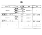
- FIG. 9 is an example showing the result of counting the genes in each section.
- the gene arranged in each compartment is either a wild type of the target gene in the database 404, a mutant type of the target gene, a pseudogene of the target gene, or neither. Is determined.
- the number of wild types of the target gene (the number of compartments in which the wild type of the target gene is placed), the number of mutant types of the target gene (the number of compartments in which the mutant type of the target gene is placed), and the target.
- Count the number of pseudogenes of the gene the number of compartments in which the pseudogenes of the target gene are placed).
- the relationship between the number of target genes (total number of wild-type and mutant types) and the number of pseudogenes is determined. The determination is made, for example, based on whether the measured ratio of the number of pseudogenes to the number of genes of interest matches the ratio recorded in database 404.
- the gene A shown in FIG. 5 when the gene A shown in FIG. 5 is detected, if the measured ratio of the number of pseudogenes to the number of target genes is 1, it is determined that the gene A is suitable, and if it is not 1, it is suitable. It is judged that it is not.
- the determination of conformity may be performed using a range. For example, when the gene A shown in FIG. 5 is detected, if the measured ratio is within the range of 0.8 to 1.2, the conformity is determined. It may be determined that it is, and if not, it may be determined that it does not conform.
- the ratio is 1 or about 1, but the ratio differs depending on the gene and is either 1/2, 1, 2, or 0.
- the measured ratios match the ratios recorded in the database 404, information indicating that they match is displayed on monitor 406. If they do not match, information indicating that they do not match (for example, information indicating that a measurement error has occurred) is displayed on monitor 406. This information can be reflected in the quality control of digital PCR. Further, if the measurement error occurs more frequently than the preset standard, an alert may be displayed on the monitor 406. This alert contains, for example, information that indicates to the user that the digital PCR system needs to be tuned.
- a sample solution (DNA solution) derived from a biological sample containing DNA is prepared.
- the sample solution may contain multiple types of DNA containing the target gene (first gene) and its pseudogene.
- This sample solution is added to the PCR reaction solution.
- the PCR reaction solution contains a DNA polymerase, a primer, a DNA intercalator or a molecular beacon, deoxyribonucleotides, and a buffer solution. This will cause the sample solution to contain a fluorescently labeled probe or DNA intercalator.
- This PCR reaction solution is divided into wells arranged in an array in the cartridge 313 (S1002).
- This step is a step of arranging the sample solution in each of the plurality of compartments.
- digital PCR processing is performed. That is, the sample solution placed in each compartment is marginally diluted, which makes digital PCR feasible.
- the cartridge 313 is set in the thermal cycler, and PCR is performed by controlling the temperature of the thermal cycler (S1003).
- S1003 This is a step of performing a nucleic acid amplification reaction in each compartment. DNA is amplified by repeating the cycle including the denaturation step, the extension step and the annealing step.
- a DNA intercalator When using a DNA intercalator, it intercalates to the amplified DNA, and when using a molecular beacon, it hybridizes to the amplified DNA. This increases the fluorescence intensity. Reaction conditions including the temperature, time, number of cycles, etc. of each step can be easily set by those skilled in the art. After PCR, when the temperature is lowered to room temperature, the DNA forms double strands.
- a fluorescence image is acquired (S1004).
- a detailed procedure example is as follows.
- the cartridge 313 is placed on the temperature control stage 312 of the DNA detector.
- the fluorescence measurement unit 401 measures the fluorescence intensity from the DNA intercalator or the molecular beacon of each well while changing the temperature of the cartridge 313 by the temperature control stage 312. As a result, a fluorescent image is acquired.
- the step of S1004 is a step of changing the temperature of each section and measuring the fluorescence intensity that changes with the temperature change for each section.
- the step S1004 may be carried out during the nucleic acid amplification reaction or after the nucleic acid amplification reaction.
- the computer 402 or other component may function as an image pickup control unit.
- the image pickup control unit causes an image pickup device (for example, a photo multiple meter 306) to take an image in order to acquire the fluorescence intensity that changes with the temperature change for each section.
- the analysis unit 403 calculates the fluorescence intensity of each minute section, and stores it in the memory 405 (S1005).
- the analysis unit 403 creates a melting curve based on the fluorescence intensity data (S1006), calculates the melting temperature using the melting curve, and stores it in the memory 405 (S1007).
- This step includes calculating the melting temperature of the double strand of DNA arranged in each compartment based on the change in fluorescence intensity with the temperature change. In this way, the measured melting temperature is obtained.
- the analysis unit 403 refers to the data regarding the reference melting temperature of the database 404, and counts the numbers of the wild type, the mutant type, and the pseudogene of the target gene based on the measured melting temperature of the memory 405 (S1008).
- the step of S1008 includes a step of determining the type of DNA for each compartment based on the reference melting temperature and the measured melting temperature, and counting the number of compartments for each type of DNA.
- the analysis unit 403 counts the number of compartments in which the target gene (first gene) is arranged and the number of compartments in which the pseudogene is arranged, using the database 404 and the memory 405. . Further, in S1008, the analysis unit 403 may determine whether or not the target gene and the pseudogene of the target gene are contained in the sample solution.
- wild type, mutant type and pseudogene can be made based on the reference melting temperature and the measured melting temperature. For example, in the case of gene A in FIG. 5, if the measured melting temperature is 63 ° C., it can be determined that the target gene is a wild type.
- This judgment may be made based on the range. For example, if the measured melting temperature for a well is within a predetermined range (eg, within ⁇ 1 ° C.) that includes the reference melting temperature recorded in database 404 for a genotype, then that genotype is in that genotype. It can be determined that the gene of is arranged. By using the range having such a width, it is possible to make a robust judgment in consideration of the permissible range.
- a predetermined range eg, within ⁇ 1 ° C.
- the analysis unit 403 determines the relationship between the number of target genes (total number of wild-type and mutant types) and the number of pseudogenes. That is, the target gene and pseudogene are discriminated from the melting temperature and the number of compartments counted. For example, it is determined whether the ratio is 1, 1/2, 2, 2, 0, or none of these. The result is output (S1009). Here, as described above, this determination may be made based on the range. For example, in the step S1009, the analysis unit 403 determines that the ratio of the number of compartments in which the pseudogene is arranged to the number of compartments in which the target gene (first gene) is arranged is within the range corresponding to 1.
- Is there is a value within the range corresponding to 1/2, is a value within the range corresponding to 2, is a value within the range corresponding to 0, or is not within either range Is determined.
- the monitor 406 outputs the number of target genes and the total number of genes in the cartridge to the monitor (S1010). For example, the number of compartments counted for each type of DNA is output.
- the fluorescence intensity information is used in determining whether the DNA of each well is positive (that is, the gene is arranged in the well) or negative (that is, the gene is not arranged in the well). May be used.
- the fluorescence intensity value itself can be used as the fluorescence intensity information. If the fluorescence intensity of a well is within a predetermined range, the well is determined to be positive, otherwise the well is determined to be negative.
- the ratio or difference of the fluorescence intensity at different temperatures may be used.
- the fluorescence intensity can be standardized by using the ratio or difference between the fluorescence intensity at a temperature lower than the reference melting temperature and the fluorescence intensity at a temperature higher than the reference melting temperature. For example, if this ratio or difference is within a predetermined range for a well, the well is determined to be positive, otherwise the well is determined to be negative.
- the influence of the fluorescence of the fluorescently labeled probe itself that is, the influence of the background can be removed.
- the method for determining the range of fluorescence intensity, the range of the reference melting temperature, and the range of the correspondence (for example, ratio) between the target gene and the number of copies of the pseudogene can be arbitrarily selected. For example, a pilot experiment may be conducted in advance, and the worker may statistically determine the result from the result, or the DNA detection system may automatically determine the result. In addition, for each digital PCR measurement, the measurement data of each well in the cartridge may be used to statistically determine a predetermined range of fluorescence intensity threshold and reference melting temperature.
- the data for statistically discriminating the DNA in the well may include any or all of the following items, or may include items other than these.
- -Fluorescent intensity at a temperature lower than the standard melting temperature -Fluorescent intensity at a temperature higher than the standard melting temperature-For fluorescence intensity at a temperature higher than the standard melting temperature, at a temperature lower than the standard melting temperature
- the sample solution to be used is not particularly limited, but any sample containing the DNA to be detected may be used, and a biological sample (body fluid, tissue, cells, excrement, etc. of animals and plants) or a soil sample (including fungi, bacteria, etc.) may be used. It can be exemplified.
- Examples of body fluids include blood, saliva, and cerebrospinal fluid.
- Blood contains cell-free DNA (cfDNA), circulating tumor DNA (ctDNA), and the like.
- Examples of the tissue include affected areas of diseases obtained by surgery or biopsy (for example, cancer tissues such as breast and liver).
- the tissue may be an already fixed tissue, for example formalin-fixed paraffin-embedded tissue section (FFPE).
- Examples of cells include cells collected by a biopsy method (at or near the affected area), blood-circulating tumor cells that circulate in the blood, and the like.
- the pretreatment of these samples is not particularly limited, and after collecting from a living body or the environment, those obtained by adding to a suspension and homogenizing or dissolving in a solution may be used as they are. It is preferable to extract or purify the contained nucleic acid.
- the oil is preferably a substance that is insoluble or sparingly soluble in the PCR reaction solution and is chemically inactive, and is preferably a substance that is stable to temperature changes at high temperatures such as PCR. Fluorine-based oil, silicone-based oil, hydrocarbon-based oil, etc. can be used.
- fluorine-based oil examples include Perfluorocarbon and Hydrofluorother. Fluorine-based oils have a longer carbon chain, which is preferable because it has lower volatility.
- silicone-based oil examples include Polyphenylmethylsyloxane and Trimethylsiloxysilite.
- hydrocarbon oil examples include mineral oil, liquid paraffin, hexadecane and the like.
- the oil may be used with the addition of a surfactant.
- a surfactant is not particularly limited, but Tween 20, Tween 80, Span80, Triton X-100 and the like can be applied.
- FIG. 11 is an example of the measurement results displayed on the monitor. This example represents the results of measurement using two types of cancer-related genes A and B as target genes. In this example, the same number of cancer-related genes A and B have been detected.
- the number of counted DNAs contained in the sample solution may be displayed for each type of cancer-related gene and type of mutation, or as shown in FIG. 11B, the cancer-related gene.
- the percentage of counted DNA contained in the sample solution may be displayed for each type of and mutation type. In the example of FIG. 11B, the proportion of the mutant gene in the target gene is displayed.
- the total number of cancer-related genes may be displayed (in this example, the same number of cancer-related genes A and B are detected).
- the total number of genes may be calculated from the total of the wild type and the mutant type of the target gene, or the value may be corrected by the measurement result of the pseudogene of the target gene, or the target. It may be a value calculated from the number of genes or the number of pseudogenes.
- the result displayed on the monitor may be the number or proportion of the sample solution DNA as shown in FIG. 11 or the sample solution in two axes of the fluorescence intensity of the fluorescently labeled probe and the measured melting temperature as shown in FIG. It may be a graph in which measured values are plotted, or both may be included. It may also include a histogram plotting the number of DNAs in the sample solution relative to the fluorescence intensity of the fluorescently labeled probe or the measured melting temperature.
- the range regarding the fluorescence intensity of the fluorescently labeled probe used when counting the number of DNA may be arbitrarily changed by the user. Further, the range regarding the reference melting temperature used when counting the number of DNAs may be arbitrarily changed by the user.
- the DNA detection system may accept operations to change these and change the applicable range. In this way, the user can look at the graph or histogram of the measurement results, change the range of fluorescence intensity and / or reference melting temperature, and recount the number of DNA in the sample solution within the new range. ..
- the number of pseudogene counts may be displayed. Further, the DNA detection device may determine whether or not the correspondence between the count number of the target gene and the count number of the pseudogene is appropriate, and display the result on the monitor 406. For example, it is determined whether the ratio of the Pseudogene count to the count of the target gene matches the value (or range) stored in the database 404, and if so, these counts match. Information indicating that (for example, a message indicating that the measurement was performed normally) is displayed on the monitor 406, and if they do not match, information indicating that these counts do not match (for example, a measurement error has occurred) is displayed. The message shown) may be displayed on the monitor 406.
- the sample solution is treated as a solution in a well or a droplet, it may be expressed as the number of wells or the number of droplets instead of the number of DNA in the sample solution.
- the DNA detection device may be, for example, the DNA detection device according to the first embodiment, and the device described in detail in the above section (2) is used, and the method described in detail in the above section (1) is used as the DNA detection method. To execute.
- Yet another embodiment of the present invention is a recording medium for storing the above program.
- Example 10 the melting temperature of DNA in the well is measured using a fluorescently labeled probe, and the result of discriminating the BRAF gene and its pseudogene is shown.
- the BRAF gene exists on the 7th chromosome, which is an autosomal chromosome, and its pseudogene, BRAF P1, exists on the X chromosome.
- the sample used in this example is the genomic DNA of HCT116, which is a human colorectal cancer-derived cell line, and since this is the genomic DNA of a man, the number of copies of the BRAF gene pseudogene is the number of copies of the wild type and the mutant type. Should be half of the total.
- the BRAF gene For the BRAF gene, prepare wild-type and V600E mutant genomic DNA (final concentration 133 molecules / ⁇ L). In addition to this, a forward primer (final concentration 0.25 ⁇ M), a reverse primer (final concentration 2.0 ⁇ M), a fluorescently labeled probe corresponding to the wild type (final concentration 0.5 ⁇ M), and a 1x master mix (DNA) required for PCR. Polymerase and dNTP) were added to prepare a PCR reaction solution. At this time, the concentration of the primer pair was added so as to be asymmetric so that the complementary DNA strand of the fluorescently labeled probe was excessively amplified.
- primers and probes are as follows. It should be noted that all fluorescently labeled probes have complementary sequences near both ends and are designed so that they form a double chain within the molecule. In addition, CAL Fluor Red 610 as a fluorescent dye is bound to the 5'end, and BHQ-2 is bound to the 3'end as a quencher.
- Forward primer 5'-CATGAAGACCTCACAGTAAAAAATAGGTGAT-3'(SEQ ID NO: 1)
- Reverse primer 5'-TGGGACCCACTCCATCGA-3' (SEQ ID NO: 2) Fluorescent labeled probe corresponding to BRAF wild type: 5'-GGTCTAGCTACAGTGAAATC-3'(SEQ ID NO: 3)
- the PCR reaction was performed at 96 ° C. for 10 minutes, followed by 59 cycles (60 ° C., 2 minutes followed by 98 ° C., 30 seconds), and finally treated at 60 ° C. for 2 minutes.
- the chip provided with the wells was cooled from 85 ° C. to 50 ° C. on a temperature control stage, and the change in fluorescence intensity of each well was observed, and the melting curve was measured and analyzed.
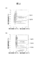
- results are shown in FIG. When two or more fluorescent dyes are used, the results shown in FIG. 12 can be obtained for each dye.
- FIG. 12A plots the results of measuring a sample containing the wild-type BRAF gene and its pseudogene on the horizontal axis, plotting the ratio of the fluorescence intensity at 50 ° C to the fluorescence intensity at 85 ° C on the horizontal axis, and plotting the measured melting temperature on the vertical axis. It was done.
- the population 1201 (for example, in the range of 64 ° C to 66 ° C), which is divided into two distributions depending on the difference in the measured melting temperature and has a distribution around 65 ° C, is a well containing the wild type of the BRAF gene, and the distribution is around 61 ° C.
- Population 1203 eg, in the range of 60 ° C. to 62 ° C.
- FIG. 12B is the result of measuring a sample containing the wild type, V600E mutant type and pseudogene of the BRAF gene.
- the population 1201 (for example, within the range of 64 ° C to 66 ° C), which is divided into three distributions depending on the difference in the measured melting temperature and has a distribution around 65 ° C, is a well containing the wild type of the BRAF gene, and the distribution is around 61 ° C.
- the population 1203 (for example, within the range of 60 ° C. to 62 ° C.) is a well containing the BRAF gene pseudogene, and the population 1202 (for example, within the range of 57 ° C. to 59 ° C.) having a distribution around 58 ° C.
- Well containing the V600E variant Well containing the V600E variant.
- the BRAF gene pseudogene count is half the BRAF gene wild-type count in FIG. 12A, and the BRAF gene pseudogene count is shown in FIG. 12B. The number was half of the total number of BRAF gene wild-type and V600E counts.
- each of the target gene and pseudogene is discriminated and counted using the measured melting temperature for genotyping in digital PCR, and compared with the correspondence of the number of copies obtained in advance from the position on the chromosome. By confirming that it is done, the measurement accuracy can be guaranteed.
Landscapes
- Chemical & Material Sciences (AREA)
- Life Sciences & Earth Sciences (AREA)
- Organic Chemistry (AREA)
- Engineering & Computer Science (AREA)
- Zoology (AREA)
- Wood Science & Technology (AREA)
- Proteomics, Peptides & Aminoacids (AREA)
- Health & Medical Sciences (AREA)
- Biophysics (AREA)
- General Engineering & Computer Science (AREA)
- Immunology (AREA)
- Microbiology (AREA)
- Molecular Biology (AREA)
- Analytical Chemistry (AREA)
- Physics & Mathematics (AREA)
- Genetics & Genomics (AREA)
- Biochemistry (AREA)
- Bioinformatics & Cheminformatics (AREA)
- Biotechnology (AREA)
- General Health & Medical Sciences (AREA)
- Chemical Kinetics & Catalysis (AREA)
- Measuring Or Testing Involving Enzymes Or Micro-Organisms (AREA)
- Apparatus Associated With Microorganisms And Enzymes (AREA)
Priority Applications (5)
| Application Number | Priority Date | Filing Date | Title |
|---|---|---|---|
| US17/792,630 US20230053441A1 (en) | 2020-01-16 | 2020-01-16 | Method and system for dna detection |
| CN202080091619.1A CN114929894B (zh) | 2020-01-16 | 2020-01-16 | Dna检测方法以及dna检测系统 |
| PCT/JP2020/001171 WO2021144903A1 (ja) | 2020-01-16 | 2020-01-16 | Dna検出方法およびdna検出システム |
| JP2021570553A JP7432622B2 (ja) | 2020-01-16 | 2020-01-16 | Dna検出方法およびdna検出システム |
| EP20913084.8A EP4092134A4 (en) | 2020-01-16 | 2020-01-16 | METHOD AND SYSTEM FOR DNA DETECTION |
Applications Claiming Priority (1)
| Application Number | Priority Date | Filing Date | Title |
|---|---|---|---|
| PCT/JP2020/001171 WO2021144903A1 (ja) | 2020-01-16 | 2020-01-16 | Dna検出方法およびdna検出システム |
Publications (1)
| Publication Number | Publication Date |
|---|---|
| WO2021144903A1 true WO2021144903A1 (ja) | 2021-07-22 |
Family
ID=76864572
Family Applications (1)
| Application Number | Title | Priority Date | Filing Date |
|---|---|---|---|
| PCT/JP2020/001171 Ceased WO2021144903A1 (ja) | 2020-01-16 | 2020-01-16 | Dna検出方法およびdna検出システム |
Country Status (5)
| Country | Link |
|---|---|
| US (1) | US20230053441A1 (https=) |
| EP (1) | EP4092134A4 (https=) |
| JP (1) | JP7432622B2 (https=) |
| CN (1) | CN114929894B (https=) |
| WO (1) | WO2021144903A1 (https=) |
Families Citing this family (1)
| Publication number | Priority date | Publication date | Assignee | Title |
|---|---|---|---|---|
| JP2025034360A (ja) * | 2023-08-31 | 2025-03-13 | 株式会社日立製作所 | Dna検出方法およびdna検出キット |
Citations (4)
| Publication number | Priority date | Publication date | Assignee | Title |
|---|---|---|---|---|
| JP2013521764A (ja) * | 2010-02-12 | 2013-06-13 | レインダンス テクノロジーズ, インコーポレイテッド | デジタル検体分析 |
| WO2017135396A1 (ja) * | 2016-02-03 | 2017-08-10 | ジェノダイブファーマ株式会社 | Pcrを用いないキャプチャー法によるhla遺伝子タイピング用プローブセット及びそれを用いたタイピング方法 |
| JP2018108063A (ja) * | 2017-01-05 | 2018-07-12 | 株式会社日立製作所 | ドロップレットデジタルpcrの測定方法および測定装置 |
| JP2019213513A (ja) * | 2018-06-14 | 2019-12-19 | 株式会社日立製作所 | デジタルpcrの測定方法および測定装置 |
Family Cites Families (8)
| Publication number | Priority date | Publication date | Assignee | Title |
|---|---|---|---|---|
| JP5017552B2 (ja) * | 2006-08-24 | 2012-09-05 | 社会医療法人大雄会 | 遺伝子検査方法及び遺伝子検査方法に使用されるキット |
| EP2224017A4 (en) * | 2007-12-26 | 2011-05-04 | Arkray Inc | PROCESS FOR INCREASING THE NUCLEIC ACID TARGET SEQUENCE AND PROBE USED THEREFOR |
| US9840737B2 (en) * | 2010-06-02 | 2017-12-12 | Canon U.S. Life Sciences, Inc. | Methods and systems for sequential determination of genetic mutations and/or variants |
| EP2663652B1 (en) * | 2011-01-11 | 2018-11-14 | Roche Diagniostics GmbH | High resolution melting analysis as a prescreening tool |
| EP2994539A1 (en) * | 2013-05-08 | 2016-03-16 | Roche Diagnostics GmbH | Non-invasive early detection of solid organ transplant rejection by quantitative analysis of mixtures by deep sequencing of hla gene amplicons using next generation systems |
| EP2878374B1 (en) * | 2013-11-29 | 2021-05-12 | IMEC vzw | Method for performing digital PCR |
| US11915795B2 (en) * | 2016-12-23 | 2024-02-27 | The Regents Of The University Of California | Method and device for digital high resolution melt |
| CN107099609A (zh) * | 2017-06-19 | 2017-08-29 | 东莞市妇幼保健院 | 一种微滴式数字pcr检测低比例痕量目标基因的遗传分析方法 |
-
2020
- 2020-01-16 US US17/792,630 patent/US20230053441A1/en active Pending
- 2020-01-16 JP JP2021570553A patent/JP7432622B2/ja active Active
- 2020-01-16 WO PCT/JP2020/001171 patent/WO2021144903A1/ja not_active Ceased
- 2020-01-16 EP EP20913084.8A patent/EP4092134A4/en active Pending
- 2020-01-16 CN CN202080091619.1A patent/CN114929894B/zh active Active
Patent Citations (4)
| Publication number | Priority date | Publication date | Assignee | Title |
|---|---|---|---|---|
| JP2013521764A (ja) * | 2010-02-12 | 2013-06-13 | レインダンス テクノロジーズ, インコーポレイテッド | デジタル検体分析 |
| WO2017135396A1 (ja) * | 2016-02-03 | 2017-08-10 | ジェノダイブファーマ株式会社 | Pcrを用いないキャプチャー法によるhla遺伝子タイピング用プローブセット及びそれを用いたタイピング方法 |
| JP2018108063A (ja) * | 2017-01-05 | 2018-07-12 | 株式会社日立製作所 | ドロップレットデジタルpcrの測定方法および測定装置 |
| JP2019213513A (ja) * | 2018-06-14 | 2019-12-19 | 株式会社日立製作所 | デジタルpcrの測定方法および測定装置 |
Non-Patent Citations (5)
| Title |
|---|
| GENOME RES, vol. 10, 1996, pages 986 - 994 |
| LEBLANC MARISSA A., PENNEY LYNETTE S., GASTON DANIEL, SHI YUHAO, ABERG ERIKA, NIGHTINGALE MATHEW, JIANG HAIYAN, GILLETT ROXANNE M.: "A novel rearrangement of occludin causes brain calcification and renal dysfunction", HUMAN GENETIC, vol. 132, no. 11, November 2013 (2013-11-01), pages 1223 - 1234, XP055841154 * |
| REN JIAN-JUN, MENG XING-KAI: "A relative quantitative method to detect OCT4A gene expression by exon-junction primer and locked nucleic acid-modified probe", JOURNAL OF ZHEJIANG UNIVERSITY SCIENCE B, vol. 12, no. 2, February 2011 (2011-02-01), pages 149 - 155, XP055841163 * |
| S HIMAZAKI, Y. ET AL.: "Parallel evaluation of melting temperatures of DNAs in the arrayed droplets through the fluorescence from DNA intercalators", ANAL. CHEM., vol. 89, no. 12, 7 June 2017 (2017-06-07), pages 6305 - 6308, XP055513407, DOI: 10.1021/acs.analchem.7b01343 * |
| ZIZA KAREN CHINOCA, LIAO ADOLFO WENJAW, DEZAN MARCIA, DINARDO CARLA LUANA, JENS EDUARDO, FRANCISCO ROSSANA PULCINELI VIEIRA, JUNIO: "Determination of fetal RHD genotype including the RHD pseudogene in maternal plasma", JOURNAL OF CLINICAL LABORATORY ANALYSIS, vol. 31, no. 3, May 2017 (2017-05-01), pages e22052, XP055841172 * |
Also Published As
| Publication number | Publication date |
|---|---|
| JP7432622B2 (ja) | 2024-02-16 |
| US20230053441A1 (en) | 2023-02-23 |
| EP4092134A1 (en) | 2022-11-23 |
| CN114929894B (zh) | 2025-11-11 |
| JPWO2021144903A1 (https=) | 2021-07-22 |
| CN114929894A (zh) | 2022-08-19 |
| EP4092134A4 (en) | 2023-10-04 |
Similar Documents
| Publication | Publication Date | Title |
|---|---|---|
| JP7545511B2 (ja) | デジタルpcrの測定方法および測定装置 | |
| US12018319B2 (en) | Method and device for digital PCR measurement | |
| CN102203287B (zh) | 增加样本和/或靶通量的测定方法 | |
| US20240102088A1 (en) | Pcr measuring method and measurement device | |
| JP7810779B2 (ja) | Dna検出方法およびdna検出システム | |
| JPWO2017170644A1 (ja) | 遺伝子変異検出法 | |
| JP6812431B2 (ja) | Dna検出方法およびそのための装置 | |
| JP7432622B2 (ja) | Dna検出方法およびdna検出システム | |
| CN118272502A (zh) | 一种检测并分辨低频突变类型的方法 | |
| JP7016382B2 (ja) | ドロップレットデジタルpcrの測定方法および測定装置 | |
| CN120569489A (zh) | 用于使用颜色组合的多重数字pcr的数据分析方法 | |
| US20180087096A1 (en) | Gene mutation detection method and fluorescence-labeled oligonucleotide used in same | |
| US20240417782A1 (en) | Method and kit for genetic analysis | |
| EP4541906A1 (en) | Primer, dna detection method, and dna detection kit | |
| Jung et al. | Portable duplex digital PCR for on-site detection of IDH mutations in gliomas | |
| WO2025076130A1 (en) | Methods and compositions for analyzing nucleic acids | |
| JP2016171763A (ja) | 遺伝子解析システムの保証方法 |
Legal Events
| Date | Code | Title | Description |
|---|---|---|---|
| 121 | Ep: the epo has been informed by wipo that ep was designated in this application |
Ref document number: 20913084 Country of ref document: EP Kind code of ref document: A1 |
|
| ENP | Entry into the national phase |
Ref document number: 2021570553 Country of ref document: JP Kind code of ref document: A |
|
| NENP | Non-entry into the national phase |
Ref country code: DE |
|
| ENP | Entry into the national phase |
Ref document number: 2020913084 Country of ref document: EP Effective date: 20220816 |