WO2021141089A1 - 糸および布 - Google Patents
糸および布 Download PDFInfo
- Publication number
- WO2021141089A1 WO2021141089A1 PCT/JP2021/000385 JP2021000385W WO2021141089A1 WO 2021141089 A1 WO2021141089 A1 WO 2021141089A1 JP 2021000385 W JP2021000385 W JP 2021000385W WO 2021141089 A1 WO2021141089 A1 WO 2021141089A1
- Authority
- WO
- WIPO (PCT)
- Prior art keywords
- thread
- yarn
- electric field
- potential
- relative permittivity
- Prior art date
Links
- 239000004744 fabric Substances 0.000 title claims abstract description 21
- 230000000844 anti-bacterial effect Effects 0.000 claims description 69
- 229920000642 polymer Polymers 0.000 claims description 55
- JVTAAEKCZFNVCJ-REOHCLBHSA-N L-lactic acid Chemical compound C[C@H](O)C(O)=O JVTAAEKCZFNVCJ-REOHCLBHSA-N 0.000 claims description 40
- 229920001432 poly(L-lactide) Polymers 0.000 claims description 35
- 239000003795 chemical substances by application Substances 0.000 claims description 34
- 239000000463 material Substances 0.000 claims description 34
- 239000012756 surface treatment agent Substances 0.000 claims description 27
- 239000002216 antistatic agent Substances 0.000 claims description 25
- 229910044991 metal oxide Inorganic materials 0.000 claims description 18
- 150000004706 metal oxides Chemical class 0.000 claims description 18
- GWEVSGVZZGPLCZ-UHFFFAOYSA-N Titan oxide Chemical group O=[Ti]=O GWEVSGVZZGPLCZ-UHFFFAOYSA-N 0.000 claims description 6
- JOYRKODLDBILNP-UHFFFAOYSA-N Ethyl urethane Chemical compound CCOC(N)=O JOYRKODLDBILNP-UHFFFAOYSA-N 0.000 claims description 5
- 150000002148 esters Chemical class 0.000 claims description 3
- OGIDPMRJRNCKJF-UHFFFAOYSA-N titanium oxide Inorganic materials [Ti]=O OGIDPMRJRNCKJF-UHFFFAOYSA-N 0.000 claims description 3
- 230000005684 electric field Effects 0.000 description 107
- 239000000835 fiber Substances 0.000 description 56
- 239000000523 sample Substances 0.000 description 36
- 238000005259 measurement Methods 0.000 description 33
- 238000000034 method Methods 0.000 description 33
- 239000004626 polylactic acid Substances 0.000 description 32
- 239000003921 oil Substances 0.000 description 24
- 229920000747 poly(lactic acid) Polymers 0.000 description 24
- 241000233866 Fungi Species 0.000 description 19
- 230000000704 physical effect Effects 0.000 description 19
- 230000003287 optical effect Effects 0.000 description 18
- 241000894006 Bacteria Species 0.000 description 16
- 241000223238 Trichophyton Species 0.000 description 13
- UQDJGEHQDNVPGU-UHFFFAOYSA-N serine phosphoethanolamine Chemical compound [NH3+]CCOP([O-])(=O)OCC([NH3+])C([O-])=O UQDJGEHQDNVPGU-UHFFFAOYSA-N 0.000 description 13
- JVTAAEKCZFNVCJ-UWTATZPHSA-N D-lactic acid Chemical compound C[C@@H](O)C(O)=O JVTAAEKCZFNVCJ-UWTATZPHSA-N 0.000 description 11
- 229940022769 d- lactic acid Drugs 0.000 description 11
- 238000004128 high performance liquid chromatography Methods 0.000 description 11
- 229930182843 D-Lactic acid Natural products 0.000 description 10
- 238000002360 preparation method Methods 0.000 description 10
- GPTONYMQFTZPKC-UHFFFAOYSA-N sulfamethoxydiazine Chemical compound N1=CC(OC)=CN=C1NS(=O)(=O)C1=CC=C(N)C=C1 GPTONYMQFTZPKC-UHFFFAOYSA-N 0.000 description 10
- 230000000694 effects Effects 0.000 description 9
- 238000012360 testing method Methods 0.000 description 9
- 239000011248 coating agent Substances 0.000 description 8
- 238000000576 coating method Methods 0.000 description 8
- 239000003599 detergent Substances 0.000 description 8
- 238000004519 manufacturing process Methods 0.000 description 8
- XLYOFNOQVPJJNP-UHFFFAOYSA-N water Substances O XLYOFNOQVPJJNP-UHFFFAOYSA-N 0.000 description 8
- 238000011160 research Methods 0.000 description 7
- 238000009987 spinning Methods 0.000 description 7
- 241000893966 Trichophyton verrucosum Species 0.000 description 6
- 239000003989 dielectric material Substances 0.000 description 6
- 239000000178 monomer Substances 0.000 description 6
- 239000001301 oxygen Substances 0.000 description 6
- 229910052760 oxygen Inorganic materials 0.000 description 6
- 230000009471 action Effects 0.000 description 5
- 210000000170 cell membrane Anatomy 0.000 description 5
- 238000000691 measurement method Methods 0.000 description 5
- 230000007246 mechanism Effects 0.000 description 5
- 229920000728 polyester Polymers 0.000 description 5
- 230000008569 process Effects 0.000 description 5
- 238000012545 processing Methods 0.000 description 5
- 230000005616 pyroelectricity Effects 0.000 description 5
- 230000000638 stimulation Effects 0.000 description 5
- 239000000126 substance Substances 0.000 description 5
- 238000005406 washing Methods 0.000 description 5
- 239000002033 PVDF binder Substances 0.000 description 4
- 238000010521 absorption reaction Methods 0.000 description 4
- 210000004027 cell Anatomy 0.000 description 4
- 238000010586 diagram Methods 0.000 description 4
- 230000005611 electricity Effects 0.000 description 4
- 238000004520 electroporation Methods 0.000 description 4
- -1 for example Polymers 0.000 description 4
- 239000007788 liquid Substances 0.000 description 4
- 239000000203 mixture Substances 0.000 description 4
- 229920002981 polyvinylidene fluoride Polymers 0.000 description 4
- 230000003313 weakening effect Effects 0.000 description 4
- 238000002441 X-ray diffraction Methods 0.000 description 3
- QVGXLLKOCUKJST-UHFFFAOYSA-N atomic oxygen Chemical compound [O] QVGXLLKOCUKJST-UHFFFAOYSA-N 0.000 description 3
- 230000008859 change Effects 0.000 description 3
- 150000001875 compounds Chemical class 0.000 description 3
- 239000004020 conductor Substances 0.000 description 3
- 229920001577 copolymer Polymers 0.000 description 3
- 230000021040 cytoplasmic transport Effects 0.000 description 3
- 238000001035 drying Methods 0.000 description 3
- 239000002657 fibrous material Substances 0.000 description 3
- 235000013305 food Nutrition 0.000 description 3
- 239000004973 liquid crystal related substance Substances 0.000 description 3
- 239000002861 polymer material Substances 0.000 description 3
- 150000003254 radicals Chemical class 0.000 description 3
- WHBMMWSBFZVSSR-UHFFFAOYSA-N 3-hydroxybutyric acid Chemical compound CC(O)CC(O)=O WHBMMWSBFZVSSR-UHFFFAOYSA-N 0.000 description 2
- 241000282320 Panthera leo Species 0.000 description 2
- 229910010413 TiO 2 Inorganic materials 0.000 description 2
- 208000002474 Tinea Diseases 0.000 description 2
- XLOMVQKBTHCTTD-UHFFFAOYSA-N Zinc monoxide Chemical compound [Zn]=O XLOMVQKBTHCTTD-UHFFFAOYSA-N 0.000 description 2
- 239000003990 capacitor Substances 0.000 description 2
- 239000000919 ceramic Substances 0.000 description 2
- 239000013626 chemical specie Substances 0.000 description 2
- 238000005520 cutting process Methods 0.000 description 2
- 239000002781 deodorant agent Substances 0.000 description 2
- 238000006073 displacement reaction Methods 0.000 description 2
- 238000007730 finishing process Methods 0.000 description 2
- 230000006870 function Effects 0.000 description 2
- 238000001891 gel spinning Methods 0.000 description 2
- 230000035784 germination Effects 0.000 description 2
- 230000036541 health Effects 0.000 description 2
- 229920001519 homopolymer Polymers 0.000 description 2
- 230000002147 killing effect Effects 0.000 description 2
- JVTAAEKCZFNVCJ-UHFFFAOYSA-N lactic acid Chemical compound CC(O)C(O)=O JVTAAEKCZFNVCJ-UHFFFAOYSA-N 0.000 description 2
- 244000005700 microbiome Species 0.000 description 2
- 239000011941 photocatalyst Substances 0.000 description 2
- 229920003223 poly(pyromellitimide-1,4-diphenyl ether) Polymers 0.000 description 2
- 230000009467 reduction Effects 0.000 description 2
- 239000002904 solvent Substances 0.000 description 2
- 239000007921 spray Substances 0.000 description 2
- 239000000725 suspension Substances 0.000 description 2
- 210000004243 sweat Anatomy 0.000 description 2
- 238000004804 winding Methods 0.000 description 2
- KXJGSNRAQWDDJT-UHFFFAOYSA-N 1-acetyl-5-bromo-2h-indol-3-one Chemical compound BrC1=CC=C2N(C(=O)C)CC(=O)C2=C1 KXJGSNRAQWDDJT-UHFFFAOYSA-N 0.000 description 1
- 241000238876 Acari Species 0.000 description 1
- 241001480043 Arthrodermataceae Species 0.000 description 1
- 206010014357 Electric shock Diseases 0.000 description 1
- 206010020751 Hypersensitivity Diseases 0.000 description 1
- 241001465754 Metazoa Species 0.000 description 1
- VYPSYNLAJGMNEJ-UHFFFAOYSA-N Silicium dioxide Chemical compound O=[Si]=O VYPSYNLAJGMNEJ-UHFFFAOYSA-N 0.000 description 1
- OUUQCZGPVNCOIJ-UHFFFAOYSA-M Superoxide Chemical compound [O-][O] OUUQCZGPVNCOIJ-UHFFFAOYSA-M 0.000 description 1
- 241000700605 Viruses Species 0.000 description 1
- 208000027418 Wounds and injury Diseases 0.000 description 1
- 239000000654 additive Substances 0.000 description 1
- 230000000996 additive effect Effects 0.000 description 1
- 208000030961 allergic reaction Diseases 0.000 description 1
- 150000001412 amines Chemical class 0.000 description 1
- 230000003373 anti-fouling effect Effects 0.000 description 1
- 229910000410 antimony oxide Inorganic materials 0.000 description 1
- 238000004364 calculation method Methods 0.000 description 1
- 230000003197 catalytic effect Effects 0.000 description 1
- 210000002421 cell wall Anatomy 0.000 description 1
- 229920002678 cellulose Polymers 0.000 description 1
- 239000001913 cellulose Substances 0.000 description 1
- 229920002301 cellulose acetate Polymers 0.000 description 1
- 229910000420 cerium oxide Inorganic materials 0.000 description 1
- 230000000052 comparative effect Effects 0.000 description 1
- 239000002131 composite material Substances 0.000 description 1
- 230000008878 coupling Effects 0.000 description 1
- 238000010168 coupling process Methods 0.000 description 1
- 238000005859 coupling reaction Methods 0.000 description 1
- 230000006378 damage Effects 0.000 description 1
- 238000004332 deodorization Methods 0.000 description 1
- 230000037304 dermatophytes Effects 0.000 description 1
- 238000011161 development Methods 0.000 description 1
- 230000018109 developmental process Effects 0.000 description 1
- 238000000113 differential scanning calorimetry Methods 0.000 description 1
- 239000003814 drug Substances 0.000 description 1
- 229940079593 drug Drugs 0.000 description 1
- 230000027721 electron transport chain Effects 0.000 description 1
- 238000010041 electrostatic spinning Methods 0.000 description 1
- 238000005516 engineering process Methods 0.000 description 1
- JBKVHLHDHHXQEQ-UHFFFAOYSA-N epsilon-caprolactam Chemical class O=C1CCCCCN1 JBKVHLHDHHXQEQ-UHFFFAOYSA-N 0.000 description 1
- 230000001747 exhibiting effect Effects 0.000 description 1
- 239000002979 fabric softener Substances 0.000 description 1
- 238000010438 heat treatment Methods 0.000 description 1
- TUJKJAMUKRIRHC-UHFFFAOYSA-N hydroxyl Chemical compound [OH] TUJKJAMUKRIRHC-UHFFFAOYSA-N 0.000 description 1
- 230000006872 improvement Effects 0.000 description 1
- 229910003437 indium oxide Inorganic materials 0.000 description 1
- PJXISJQVUVHSOJ-UHFFFAOYSA-N indium(iii) oxide Chemical compound [O-2].[O-2].[O-2].[In+3].[In+3] PJXISJQVUVHSOJ-UHFFFAOYSA-N 0.000 description 1
- 229910010272 inorganic material Inorganic materials 0.000 description 1
- 239000011147 inorganic material Substances 0.000 description 1
- 238000009413 insulation Methods 0.000 description 1
- 239000012212 insulator Substances 0.000 description 1
- 230000003993 interaction Effects 0.000 description 1
- 230000001788 irregular Effects 0.000 description 1
- 238000009940 knitting Methods 0.000 description 1
- 239000004310 lactic acid Substances 0.000 description 1
- 235000014655 lactic acid Nutrition 0.000 description 1
- 239000000395 magnesium oxide Substances 0.000 description 1
- CPLXHLVBOLITMK-UHFFFAOYSA-N magnesium oxide Inorganic materials [Mg]=O CPLXHLVBOLITMK-UHFFFAOYSA-N 0.000 description 1
- AXZKOIWUVFPNLO-UHFFFAOYSA-N magnesium;oxygen(2-) Chemical compound [O-2].[Mg+2] AXZKOIWUVFPNLO-UHFFFAOYSA-N 0.000 description 1
- 239000000155 melt Substances 0.000 description 1
- 238000002074 melt spinning Methods 0.000 description 1
- 230000000813 microbial effect Effects 0.000 description 1
- 229910000484 niobium oxide Inorganic materials 0.000 description 1
- URLJKFSTXLNXLG-UHFFFAOYSA-N niobium(5+);oxygen(2-) Chemical compound [O-2].[O-2].[O-2].[O-2].[O-2].[Nb+5].[Nb+5] URLJKFSTXLNXLG-UHFFFAOYSA-N 0.000 description 1
- QGLKJKCYBOYXKC-UHFFFAOYSA-N nonaoxidotritungsten Chemical compound O=[W]1(=O)O[W](=O)(=O)O[W](=O)(=O)O1 QGLKJKCYBOYXKC-UHFFFAOYSA-N 0.000 description 1
- 239000004745 nonwoven fabric Substances 0.000 description 1
- 239000011368 organic material Substances 0.000 description 1
- TWNQGVIAIRXVLR-UHFFFAOYSA-N oxo(oxoalumanyloxy)alumane Chemical compound O=[Al]O[Al]=O TWNQGVIAIRXVLR-UHFFFAOYSA-N 0.000 description 1
- BMMGVYCKOGBVEV-UHFFFAOYSA-N oxo(oxoceriooxy)cerium Chemical compound [Ce]=O.O=[Ce]=O BMMGVYCKOGBVEV-UHFFFAOYSA-N 0.000 description 1
- VTRUBDSFZJNXHI-UHFFFAOYSA-N oxoantimony Chemical compound [Sb]=O VTRUBDSFZJNXHI-UHFFFAOYSA-N 0.000 description 1
- BPUBBGLMJRNUCC-UHFFFAOYSA-N oxygen(2-);tantalum(5+) Chemical compound [O-2].[O-2].[O-2].[O-2].[O-2].[Ta+5].[Ta+5] BPUBBGLMJRNUCC-UHFFFAOYSA-N 0.000 description 1
- RVTZCBVAJQQJTK-UHFFFAOYSA-N oxygen(2-);zirconium(4+) Chemical compound [O-2].[O-2].[Zr+4] RVTZCBVAJQQJTK-UHFFFAOYSA-N 0.000 description 1
- 239000005022 packaging material Substances 0.000 description 1
- 244000045947 parasite Species 0.000 description 1
- 238000005191 phase separation Methods 0.000 description 1
- 230000001699 photocatalysis Effects 0.000 description 1
- 230000010287 polarization Effects 0.000 description 1
- 229920001896 polybutyrate Polymers 0.000 description 1
- 239000002952 polymeric resin Substances 0.000 description 1
- 229920001184 polypeptide Polymers 0.000 description 1
- 229920001451 polypropylene glycol Polymers 0.000 description 1
- 230000002265 prevention Effects 0.000 description 1
- 102000004196 processed proteins & peptides Human genes 0.000 description 1
- 108090000765 processed proteins & peptides Proteins 0.000 description 1
- 230000035755 proliferation Effects 0.000 description 1
- 239000002994 raw material Substances 0.000 description 1
- 229920005989 resin Polymers 0.000 description 1
- 230000027756 respiratory electron transport chain Effects 0.000 description 1
- 229910052814 silicon oxide Inorganic materials 0.000 description 1
- 239000007790 solid phase Substances 0.000 description 1
- 241000894007 species Species 0.000 description 1
- 238000010186 staining Methods 0.000 description 1
- 239000004094 surface-active agent Substances 0.000 description 1
- 229910001936 tantalum oxide Inorganic materials 0.000 description 1
- 239000004753 textile Substances 0.000 description 1
- XOLBLPGZBRYERU-UHFFFAOYSA-N tin dioxide Chemical compound O=[Sn]=O XOLBLPGZBRYERU-UHFFFAOYSA-N 0.000 description 1
- 229910001887 tin oxide Inorganic materials 0.000 description 1
- 238000012546 transfer Methods 0.000 description 1
- 229940049890 trichophyton (fungus) Drugs 0.000 description 1
- 229910001930 tungsten oxide Inorganic materials 0.000 description 1
- 238000009941 weaving Methods 0.000 description 1
- 239000002759 woven fabric Substances 0.000 description 1
- 239000011787 zinc oxide Substances 0.000 description 1
- 229910001928 zirconium oxide Inorganic materials 0.000 description 1
Images


Classifications
-
- D—TEXTILES; PAPER
- D02—YARNS; MECHANICAL FINISHING OF YARNS OR ROPES; WARPING OR BEAMING
- D02G—CRIMPING OR CURLING FIBRES, FILAMENTS, THREADS, OR YARNS; YARNS OR THREADS
- D02G3/00—Yarns or threads, e.g. fancy yarns; Processes or apparatus for the production thereof, not otherwise provided for
- D02G3/44—Yarns or threads characterised by the purpose for which they are designed
- D02G3/441—Yarns or threads with antistatic, conductive or radiation-shielding properties
-
- D—TEXTILES; PAPER
- D02—YARNS; MECHANICAL FINISHING OF YARNS OR ROPES; WARPING OR BEAMING
- D02G—CRIMPING OR CURLING FIBRES, FILAMENTS, THREADS, OR YARNS; YARNS OR THREADS
- D02G3/00—Yarns or threads, e.g. fancy yarns; Processes or apparatus for the production thereof, not otherwise provided for
- D02G3/02—Yarns or threads characterised by the material or by the materials from which they are made
-
- D—TEXTILES; PAPER
- D02—YARNS; MECHANICAL FINISHING OF YARNS OR ROPES; WARPING OR BEAMING
- D02G—CRIMPING OR CURLING FIBRES, FILAMENTS, THREADS, OR YARNS; YARNS OR THREADS
- D02G3/00—Yarns or threads, e.g. fancy yarns; Processes or apparatus for the production thereof, not otherwise provided for
- D02G3/44—Yarns or threads characterised by the purpose for which they are designed
- D02G3/449—Yarns or threads with antibacterial properties
-
- D—TEXTILES; PAPER
- D06—TREATMENT OF TEXTILES OR THE LIKE; LAUNDERING; FLEXIBLE MATERIALS NOT OTHERWISE PROVIDED FOR
- D06M—TREATMENT, NOT PROVIDED FOR ELSEWHERE IN CLASS D06, OF FIBRES, THREADS, YARNS, FABRICS, FEATHERS OR FIBROUS GOODS MADE FROM SUCH MATERIALS
- D06M11/00—Treating fibres, threads, yarns, fabrics or fibrous goods made from such materials, with inorganic substances or complexes thereof; Such treatment combined with mechanical treatment, e.g. mercerising
- D06M11/32—Treating fibres, threads, yarns, fabrics or fibrous goods made from such materials, with inorganic substances or complexes thereof; Such treatment combined with mechanical treatment, e.g. mercerising with oxygen, ozone, ozonides, oxides, hydroxides or percompounds; Salts derived from anions with an amphoteric element-oxygen bond
- D06M11/36—Treating fibres, threads, yarns, fabrics or fibrous goods made from such materials, with inorganic substances or complexes thereof; Such treatment combined with mechanical treatment, e.g. mercerising with oxygen, ozone, ozonides, oxides, hydroxides or percompounds; Salts derived from anions with an amphoteric element-oxygen bond with oxides, hydroxides or mixed oxides; with salts derived from anions with an amphoteric element-oxygen bond
- D06M11/46—Oxides or hydroxides of elements of Groups 4 or 14 of the Periodic Table; Titanates; Zirconates; Stannates; Plumbates
-
- D—TEXTILES; PAPER
- D06—TREATMENT OF TEXTILES OR THE LIKE; LAUNDERING; FLEXIBLE MATERIALS NOT OTHERWISE PROVIDED FOR
- D06M—TREATMENT, NOT PROVIDED FOR ELSEWHERE IN CLASS D06, OF FIBRES, THREADS, YARNS, FABRICS, FEATHERS OR FIBROUS GOODS MADE FROM SUCH MATERIALS
- D06M15/00—Treating fibres, threads, yarns, fabrics, or fibrous goods made from such materials, with macromolecular compounds; Such treatment combined with mechanical treatment
- D06M15/19—Treating fibres, threads, yarns, fabrics, or fibrous goods made from such materials, with macromolecular compounds; Such treatment combined with mechanical treatment with synthetic macromolecular compounds
- D06M15/37—Macromolecular compounds obtained otherwise than by reactions only involving carbon-to-carbon unsaturated bonds
- D06M15/507—Polyesters
-
- D—TEXTILES; PAPER
- D06—TREATMENT OF TEXTILES OR THE LIKE; LAUNDERING; FLEXIBLE MATERIALS NOT OTHERWISE PROVIDED FOR
- D06M—TREATMENT, NOT PROVIDED FOR ELSEWHERE IN CLASS D06, OF FIBRES, THREADS, YARNS, FABRICS, FEATHERS OR FIBROUS GOODS MADE FROM SUCH MATERIALS
- D06M15/00—Treating fibres, threads, yarns, fabrics, or fibrous goods made from such materials, with macromolecular compounds; Such treatment combined with mechanical treatment
- D06M15/19—Treating fibres, threads, yarns, fabrics, or fibrous goods made from such materials, with macromolecular compounds; Such treatment combined with mechanical treatment with synthetic macromolecular compounds
- D06M15/37—Macromolecular compounds obtained otherwise than by reactions only involving carbon-to-carbon unsaturated bonds
- D06M15/564—Polyureas, polyurethanes or other polymers having ureide or urethane links; Precondensation products forming them
-
- D—TEXTILES; PAPER
- D06—TREATMENT OF TEXTILES OR THE LIKE; LAUNDERING; FLEXIBLE MATERIALS NOT OTHERWISE PROVIDED FOR
- D06M—TREATMENT, NOT PROVIDED FOR ELSEWHERE IN CLASS D06, OF FIBRES, THREADS, YARNS, FABRICS, FEATHERS OR FIBROUS GOODS MADE FROM SUCH MATERIALS
- D06M16/00—Biochemical treatment of fibres, threads, yarns, fabrics, or fibrous goods made from such materials, e.g. enzymatic
-
- D—TEXTILES; PAPER
- D10—INDEXING SCHEME ASSOCIATED WITH SUBLASSES OF SECTION D, RELATING TO TEXTILES
- D10B—INDEXING SCHEME ASSOCIATED WITH SUBLASSES OF SECTION D, RELATING TO TEXTILES
- D10B2331/00—Fibres made from polymers obtained otherwise than by reactions only involving carbon-to-carbon unsaturated bonds, e.g. polycondensation products
- D10B2331/04—Fibres made from polymers obtained otherwise than by reactions only involving carbon-to-carbon unsaturated bonds, e.g. polycondensation products polyesters, e.g. polyethylene terephthalate [PET]
- D10B2331/041—Fibres made from polymers obtained otherwise than by reactions only involving carbon-to-carbon unsaturated bonds, e.g. polycondensation products polyesters, e.g. polyethylene terephthalate [PET] derived from hydroxy-carboxylic acids, e.g. lactones
-
- D—TEXTILES; PAPER
- D10—INDEXING SCHEME ASSOCIATED WITH SUBLASSES OF SECTION D, RELATING TO TEXTILES
- D10B—INDEXING SCHEME ASSOCIATED WITH SUBLASSES OF SECTION D, RELATING TO TEXTILES
- D10B2401/00—Physical properties
- D10B2401/13—Physical properties anti-allergenic or anti-bacterial
-
- D—TEXTILES; PAPER
- D10—INDEXING SCHEME ASSOCIATED WITH SUBLASSES OF SECTION D, RELATING TO TEXTILES
- D10B—INDEXING SCHEME ASSOCIATED WITH SUBLASSES OF SECTION D, RELATING TO TEXTILES
- D10B2401/00—Physical properties
- D10B2401/16—Physical properties antistatic; conductive
Definitions
- the present invention relates to a thread, more specifically a thread capable of forming an electric field by surface charge, and more specifically, a thread capable of generating an electric potential.
- the present invention also relates to a cloth, more specifically a cloth containing the above-mentioned threads.
- Patent Documents 1 to 8 Conventionally, many proposals have been made as fiber materials having antibacterial properties (for example, Patent Documents 1 to 8).
- an antibacterial yarn including a plurality of charge generating fibers that generate charges by external energy, for example, an external force such as tension is known (for example, Patent Document 8).
- Such an antibacterial yarn is characterized in that the state of the space between a plurality of charge generating fibers is not uniform, thereby causing a bias in electrical characteristics and locally forming a strong electric field to exhibit antibacterial properties. To do.
- the electric field strength of the electric field that can be formed becomes small depending on the state of the space between the charge generating fibers, particularly the physical properties such as the dielectric constant of the dielectric existing between the charge generating fibers, and antibacterial. It turned out that sex may not be obtained. In addition, the physical property values for which antibacterial properties can be easily confirmed were also unknown.
- the present invention has been made in view of such a problem, and a main object of the present invention is to find a physical property value at which antibacterial properties can be obtained more reliably, and to provide a thread that can be used as an antibacterial thread. To do. It is also an object of the present invention to provide a cloth comprising the above threads.
- a charge-generating fiber in other words, a fiber or filament capable of generating an electric potential and forming an electric field by generating an electric charge, as described in detail below.
- the permittivity especially the "relative permittivity”
- the value is "about 4.5”. It was found that the antibacterial property can be obtained more reliably and can be successfully used as an antibacterial thread. As a result, the invention of the yarn which achieved the above-mentioned main purpose was completed.
- the present invention provides a yarn having a potential generating filament, and the relative dielectric constant of the yarn is about 4.5 or less. Further, the present invention provides a cloth comprising the above-mentioned yarn.
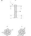
- FIG. 1 (A) is a diagram showing the configuration of thread 1 (S thread)
- FIG. 1 (B) is a cross-sectional view taken along the line AA of FIG. 1 (A)
- FIG. 1 (C) is a cross-sectional view.
- FIG. 1 (A) is a cross-sectional view taken along the line BB.
- 2 (A) and 2 (B) are views showing the relationship between the uniaxial stretching direction of polylactic acid, the electric field direction, and the deformation of the potential generating filament (or piezoelectric fiber) 10.
- 3 (A) is a diagram showing the configuration of thread 2 (Z thread)
- FIG. 3 (B) is a cross-sectional view taken along the line AA of FIG. 3 (A)
- FIG. 3 (C) is a cross-sectional view.
- FIG. 3 (A) is a cross-sectional view taken along the line BB.
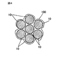
- FIG. 4 is a cross-sectional view schematically showing a cross section of the yarn of the present disclosure having a dielectric 100 around the potential generating filament 10.
- FIG. 5 is a graph showing the relationship between the relative permittivity ( ⁇ ) of the dielectric and the electric field strength (V / ⁇ m).
- FIG. 6 is a schematic diagram showing a simplified method for measuring the impedance of the yarn of the present disclosure using an LCR meter.
- FIG. 7 is a graph showing the relationship between the distance d ( ⁇ m) of the potential generating filaments and the electric field strength (V / ⁇ m).
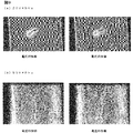
- FIG. 8 shows the results of a preliminary test for confirming the antibacterial effect of electrical stimulation.
- FIG. 9 (a) is a photograph showing the state of Trichophyton before and after voltage application for the table of FIG. 8 having 20 V ⁇ 5 Hz and FIG. 9 (b) having the same 50 V ⁇ 5 Hz.
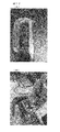
- FIG. 10 is a photograph showing Trichophyton used in the preliminary test.
- FIG. 11 is a schematic view schematically showing a method for producing a yarn bundle sample.
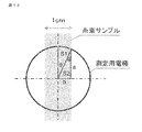
- FIG. 12 is a photograph showing an example of a method of measuring the relative permittivity of a yarn with a yarn bundle sample.
- FIG. 13 is a schematic view schematically showing a method of measuring the relative permittivity of a yarn in a yarn bundle sample.
- thread of the present disclosure may be abbreviated as "thread of the present disclosure” or simply “thread"
- thread of the present disclosure may be abbreviated as "thread of the present disclosure” or simply “thread”
- the thread of the present disclosure is formed by having a "potential generating filament", and is characterized in that its “relative permittivity" as a physical property is "about 4.5 or less". With such a configuration and characteristics, the yarn of the present disclosure can more reliably exhibit the "antibacterial property” described in detail below, and can be used as an "antibacterial yarn”.
- the threads of the present disclosure consist of, for example, a plurality of "potential generating filaments” or "electric field forming filaments".
- the number of potential generating filaments or electric field forming filaments is not particularly limited, and for example, 2 or more, 2 to 500, preferably 10 to 350, more preferably about 20 to 200 potential generating filaments are the threads of the present disclosure. May be included in.
- the "potential generating filament” or “electric field forming filament” means a fiber (or filament) capable of generating an electric charge by generating an electric charge by an external energy and forming an electric field (or an electric field forming filament).
- charge generating fiber or “charge generating filament” or “electric field forming fiber”
- potential generating filament can be used substantially synonymously with “electric field forming filament”.
- an external force specifically, the thread or the filament is deformed or distorted.
- Force and / or axial force on the thread or filament more specifically tension (eg, axial tensile force on the thread or filament) and / or stress or strain (tensile stress on the thread or filament or Tension strain) and / or external forces such as forces applied in the transverse direction of the thread or filament.
- the yarn of the present disclosure having such a potential generating filament may include a plurality of potential generating filaments having different thicknesses. Therefore, the yarns of the present disclosure may or may not have a constant diameter in the length direction.
- the potential generating filament may be a long fiber or a short fiber.
- the potential generating filament may have a length (or dimension) of, for example, 0.01 mm or more, preferably 0.1 mm or more, more preferably 1 mm or more, still more preferably 10 mm or more, 20 mm or more, or 30 mm or more.
- the length may be appropriately selected according to the desired application.
- the value of the upper limit of the length is not particularly limited, and is, for example, 10000 mm, 100 mm, 50 mm or 15 mm.
- the thickness of the potential generating filament that is, the diameter of the single fiber is not particularly limited, and may be the same (or constant) or not the same along the length of the potential generating filament.
- the potential generating filament has a single fiber diameter of, for example, 0.001 ⁇ m (1 nm) to 1 mm, preferably 0.01 ⁇ m to 500 ⁇ m, more preferably 0.1 ⁇ m to 100 ⁇ m, particularly 1 ⁇ m to 50 ⁇ m, for example 10 ⁇ m or 30 ⁇ m. Good.
- the single fiber diameter may be appropriately selected according to the desired application.
- the shape of the potential generating filament is not particularly limited, but may have, for example, a circular, elliptical, or irregular cross section. It preferably has a circular cross-sectional shape.
- the potential generating filament is a material having a photoelectric effect, a material having a pyroelectric effect, a piezoelectric effect (polarization phenomenon due to an external force) or a piezoelectricity (when a voltage is applied when a mechanical strain is applied, or conversely, when a voltage is applied. It preferably contains a material having a property of generating mechanical strain (hereinafter, may be referred to as a "piezoelectric material” or a “piezoelectric body”). Among them, it is particularly preferable to use a fiber containing a piezoelectric material (hereinafter, may be referred to as “piezoelectric fiber”).
- Piezoelectric fibers can form an electric field by pressure electricity, and more specifically, can generate an electric potential, so that a power source is not required and there is no risk of electric shock.
- the life of the piezoelectric material that can be contained in the piezoelectric fiber lasts longer than the antibacterial effect of a drug or the like. In addition, such piezoelectric fibers are unlikely to cause an allergic reaction.
- piezoelectric material can be used without particular limitation as long as it has a piezoelectric effect or piezoelectricity, and may be an inorganic material such as piezoelectric ceramics or an organic material such as a polymer.
- the "piezoelectric material” (or “piezoelectric fiber") preferably comprises a “piezoelectric polymer".
- piezoelectric polymer examples include a “piezoelectric polymer having pyroelectricity” and a “piezoelectric polymer having no pyroelectricity”.
- Piezoelectric piezoelectric polymer generally means a piezoelectric material made of a polymer material that has pyroelectricity and can generate an electric charge on its surface by giving a temperature change.
- Examples of such a piezoelectric polymer include polyvinylidene fluoride (PVDF) and the like.
- PVDF polyvinylidene fluoride
- those capable of generating an electric charge on the surface by the thermal energy of the human body are preferable.
- the piezoelectric polymer having no pyroelectricity is generally composed of a polymer material (polymer material or resin material), and is a piezoelectric polymer excluding the above-mentioned “piezoelectric polymer having pyroelectricity” (hereinafter referred to as “piezoelectric polymer”). , Sometimes referred to as “polymer piezoelectric”).
- piezoelectric polymers include polylactic acid (PLA).
- PLA polylactic acid
- PLA poly-L-lactic acid
- PLLA poly-L-lactic acid
- PDLA poly-D-lactic acid
- PDLA polymer consisting substantially only of repeating units derived from a D-lactic acid monomer
- PLA polylactic acid
- a copolymer of L-lactic acid and / or D-lactic acid and a compound copolymerizable with this L-lactic acid and / or D-lactic acid may be used.
- polylactic acid a polymer consisting of repeating units derived from a monomer selected substantially from the group consisting of L-lactic acid and D-lactic acid
- L-lactic acid and / or D-lactic acid and this L-lactic acid A mixture of "lactic acid and / or a copolymer of D-lactic acid and a copolymerizable compound" may be used.
- polylactic acid-based polymer means "polylactic acid (a polymer composed of repeating units derived from a monomer selected substantially from the group consisting of L-lactic acid and D-lactic acid)" and "L-lactic acid”. And / or D-lactic acid and a copolymer of this L-lactic acid and / or a compound copolymerizable with D-lactic acid "and mixtures thereof and the like.
- polylactic acid is particularly preferable, and it is most preferable to use L-lactic acid homopolymer (PLLA) and D-lactic acid homopolymer (PDLA).
- PLLA L-lactic acid homopolymer
- PDLA D-lactic acid homopolymer
- the polylactic acid-based polymer may have a crystalline portion, or at least a part of the polymer may be crystallized.
- the polylactic acid-based polymer it is preferable to use a polylactic acid-based polymer having piezoelectricity, in other words, a piezoelectric polylactic acid-based polymer, particularly piezoelectric polylactic acid.
- polypeptide-based for example, poly ( ⁇ -benzyl glutarate), poly ( ⁇ -methyl glutarate), etc.
- cellulose-based for example, cellulose acetate, cyanoethyl cellulose, etc.
- a polymer having optical activity such as polybutyrate (for example, poly ( ⁇ -hydroxybutyric acid)), polypropylene oxide, and a derivative thereof may be used as the polymer piezoelectric material.
- a conductor is used as a core yarn, an insulator is wound around the conductor, and a voltage is applied to the conductor to generate a charge or a potential. It may have a structure to make it.
- the yarn of the present disclosure may be a yarn obtained by simply aligning a plurality of potential generating filaments (aligned yarn or untwisted yarn), or may be a twisted yarn (twisted yarn or twisted yarn). ,
- the crimped yarn crimped yarn or false twisted yarn may be used.
- the yarn 1 can be formed by twisting a plurality of potential generating filaments 10.
- the yarn 1 is a left-handed swirl yarn (hereinafter referred to as “S yarn”) twisted by turning the potential-generating filament 10 to the left, but the potential-generating filament 10 is swiveled to the right.
- S yarn left-handed swirl yarn
- Z yarn right-handed swirl yarn twisted
- the yarn of the present disclosure may be either "S yarn” or "Z yarn” in the case of a twisted yarn.
- the distance between the potential generating filaments 10 is about 0 ⁇ m to about 10 ⁇ m, typically about 5 ⁇ m.
- the yarn of the present disclosure preferably has a relative permittivity value of "about 4.5 or less", which is the purpose described in detail below, and more reliably exhibits antibacterial properties. Can be done.
- This relative permittivity is a dimensionless numerical value, and is sometimes called a relative permittivity or a dielectric constant.
- the capacitance is measured by passing the yarn between parallel plate capacitors, and the capacitance of the yarn is calculated from the difference from the capacitance when the yarn is not passed, and the value thereof.
- the permittivity of the thread of the present disclosure can be obtained by using the capacitance of the thread and the capacitance of the thread, and can be determined by calculating using the dielectric constant of the vacuum based on the above formula.
- the method for determining the relative permittivity of the yarn is not limited to the method shown above.
- the present disclosure is made using a measuring device such as an LCR meter (for example, Precision LCR Meter (model number: E4980A) manufactured by Agilent).
- LCR meter for example, Precision LCR Meter (model number: E4980A) manufactured by Agilent.
- the relative permittivity of the yarn may be measured directly.
- the relative permittivity of the yarn can be directly measured using the yarn bundle (sample) formed by collecting the yarns of the present disclosure (see FIGS. 11 to 13).
- the measured value of the relative permittivity of the yarn bundle shows almost the same result as the calculated value of the relative permittivity of the yarn (one) of the present disclosure based on the above capacitance.
- Polylactic acid which can be used as a piezoelectric material, is a chiral polymer and has a spiral structure in the main chain. Polylactic acid can exhibit piezoelectricity when it is uniaxially stretched and the molecules are oriented. Further, heat treatment may be applied to increase the crystallinity to increase the piezoelectric constant. In other words, the "piezoelectric constant” can be increased according to the "crystallinity" ("Study of high piezoelectricity development mechanism of solid phase stretched film using polylactic acid", Journal of Seidenki Gakkai, 40, 1 (2016) ) See 38-43).
- the optical purity of polylactic acid (PLA) as a piezoelectric material is a value calculated by the following formula.
- Optical purity (%) ⁇
- the optical purity is 90% by weight or more, preferably 95% by weight or more, more preferably 98% by weight or more and 100% by weight or less, and even more preferably 99.0% by weight or more. It is 100% by weight or less, particularly preferably 99.0% by weight or more and 99.8% by weight or less.
- L-form and D-form of polylactic acid (PLA) for example, values obtained by a method using high performance liquid chromatography (HPLC) can be used.
- the crystallinity of polylactic acid (PLA) is, for example, 35% or more (specifically 35% or more and 45% or less, more specifically 42% or more and 44% or less), more preferably 50% or more, and even more preferably. Is 55% or more and 100% or less.
- the degree of crystallinity is determined by, for example, a method using a differential scanning calorimetry (DSC) (for example, DSC7000X manufactured by Hitachi High-Tech Science Co., Ltd.) or an X-ray diffraction method (XRD: X-ray diffraction) (for example, Co., Ltd.). It can be determined by a measurement method such as X-ray diffraction method using Rigaku's ultraX18).
- DSC differential scanning calorimetry
- XRD X-ray diffraction
- the potential generating filament (or piezoelectric fiber) 10 containing uniaxially stretched polylactic acid has the first axis in the thickness direction and the third axis, the first axis and the first axis in the stretching direction 900.
- the direction orthogonal to both of the three axes is defined as the second axis, it has tensor components of d 14 and d 25 as piezoelectric strain constants.
- polylactic acid can generate electric charges or potentials most efficiently when strain occurs in the direction of 45 degrees with respect to the uniaxially stretched direction.
- Mn number average molecular weight of polylactic acid
- Mw weight average molecular weight
- the molecular weight is not limited to these values.
- FIG. 2 (A) and 2 (B) are views showing the relationship between the uniaxial stretching direction of polylactic acid, the electric field direction, and the deformation of the potential generating filament (or piezoelectric fiber) 10.
- the filament 10 contracts in the direction of the first diagonal line 910A and extends in the direction of the second diagonal line 910B orthogonal to the first diagonal line 910A, an electric field is applied in the direction from the back side to the front side of the paper. Can be generated. That is, the filament 10 can generate a negative charge or potential on the front side of the paper.
- FIG. 2A when the filament 10 contracts in the direction of the first diagonal line 910A and extends in the direction of the second diagonal line 910B orthogonal to the first diagonal line 910A, an electric field is applied in the direction from the back side to the front side of the paper. Can be generated. That is, the filament 10 can generate a negative charge or potential on the front side of the paper.
- the filament 10 can generate an electric charge even when it extends in the direction of the first diagonal line 910A and contracts in the direction of the second diagonal line 910B, but the polarity is reversed and the filament 10 is on the paper surface.
- An electric field can be generated in the direction from the front side to the back side. That is, the filament 10 can generate a positive charge or potential on the front side of the paper.
- polylactic acid may have piezoelectricity due to molecular orientation treatment by stretching, crystallinity, etc., it does not need to be polled unlike other piezoelectric polymers such as polyvinylidene fluoride (PVDF) or piezoelectric ceramics. ..
- the piezoelectric constant of uniaxially stretched polylactic acid is about 5 to 30 pC / N, and has a very high piezoelectric constant among polymers. Furthermore, the piezoelectric constant of polylactic acid does not fluctuate with time and is extremely stable.
- the potential generating filament 10 is preferably a fiber having a circular cross section.
- the potential generating filament 10 is, for example, a method of extruding a piezoelectric polymer into fibers and a method of melt-spinning a piezoelectric polymer into fibers (for example, a spinning / drawing method in which a spinning step and a drawing step are performed separately.
- a dry or wet piezoelectric polymer Spinning for example, a phase separation method or a dry-wet spinning method in which a polymer as a raw material is dissolved in a solvent and extruded from a nozzle to form fibers
- a gel spinning method in which fibers are uniformly fiberized in a gel state while containing a solvent.
- the potential generating filament 10 is not limited to a circle.
- the thread 1 shown in FIG. 1 may be a thread (multifilament thread) (S thread) formed by twisting a plurality of potential generating filaments 10 containing such polylactic acid.
- the number of filaments 10 constituting the thread 1 is not particularly limited.
- the stretching direction 900 of each potential generating filament 10 coincides with the axial direction of each potential generating filament 10. Therefore, the stretching direction 900 of the potential generating filament 10 is in a state of being tilted to the left with respect to the axial direction of the yarn 1. The angle may depend on the number of twists.
- the thread 1 can form an electric field due to the potential difference that can be generated by this electric charge. This electric field can also leak into the nearby space and form a coupled electric field with other parts. Further, the potential that can be generated in the thread 1 generates an electric field between the thread 1 and the object when it is close to an object having a predetermined potential (including a ground potential) such as a human body. You can also let it.
- a predetermined potential including a ground potential
- the drawing direction 900 of the potential generating filament (or piezoelectric fiber) 10 is in a state of being inclined to the right with respect to the axial direction of the thread 2. ..
- the angle may depend on the number of times the yarn is twisted. Further, the number of filaments 10 constituting the thread 2 is not particularly limited.
- the thread 2 can also form an electric field due to the potential difference that can be generated by this electric charge. This electric field can also leak into the nearby space and form a coupled electric field with other parts. Further, the potential that can be generated in the thread 2 generates an electric field between the thread 2 and the object when it is close to an object having a predetermined potential (including a ground potential) such as a human body. You can also let it.
- a predetermined potential including a ground potential
- the polarities of the electric charges or potentials that can be generated in the thread 1 and the thread 2 are different from each other.
- the potential difference at each location can be defined by an electric field coupling circuit that can be formed by intricately entwining fibers with each other, or a circuit that can be formed by a current path that can be accidentally formed in a yarn due to moisture or the like.
- the threads of the present disclosure should not be construed as limited to the above aspects. Further, the method for producing the yarn of the present disclosure is not particularly limited, and is not limited to the above-mentioned production method.
- the yarn of the present disclosure may be provided with a "dielectric" at least in part around the potential generating filament, for example, in at least part of the surface in the longitudinal and / or circumferential direction of the filament.
- a dielectric 100 can be provided around the potential generating filament (or piezoelectric fiber) 10.
- the "dielectric" has an arbitrary configuration and is not an essential configuration of the invention.
- dielectric means a material or substance containing a material or substance having dielectric properties (property of being electrically polarized by an electric field) and / or conductivity (property of conducting electricity), for example. , Charges can be stored on its surface.
- the relative permittivity of the yarn of the present disclosure is “about".
- the relative permittivity may be adjusted more appropriately within the range of "4.5 or less", for example, "about 1 to about 4.5".
- an electric field having a larger electric field strength for example, 0.1 V / ⁇ m or more
- at least a part of the yarn or the potential generating filament of the present disclosure may be coated with a dielectric material so that the relative permittivity of the yarn is about 1 to about 4.5.
- the dielectric may be present, for example, in the longitudinal and circumferential directions of the potential generating filament, and may completely or partially cover the potential generating filament.
- the dielectric may be provided entirely or partially in the longitudinal axis direction of the potential generating filament. Further, the dielectric may be provided entirely or partially in the circumferential direction of the potential generating filament.
- the dielectric material may have a uniform thickness or a non-uniform thickness (see, for example, FIG. 4).
- the thickness of the dielectric may be larger or smaller than the fiber diameter of the potential generating filament.
- the thickness of the dielectric is preferably smaller than the fiber diameter of the potential generating filament (see FIG. 4).
- the dielectric may be provided in layers on at least a part of the surface of the thread or potential generating filament of the present disclosure, for example, in a cross-sectional view or a radial cross section of the thread or potential generating filament of the present disclosure.
- the dielectric may also be present between the plurality of potential generating filaments, and in this case, there may be a portion between the plurality of potential generating filaments in which the dielectric is not present.
- bubbles or cavities may be present in the dielectric.
- the dielectric is not particularly limited as long as it contains a material or substance having dielectric properties, conductivity, etc.
- a dielectric material for example, an oil agent, an antistatic agent, etc.
- a surface treatment agent or fiber treatment agent mainly in the textile industry may be used.
- the dielectric preferably contains an oil agent.
- an oil agent that can be used as a surface treatment agent (or fiber treatment agent) that can be used in the production of the potential generating filament can be used.
- an oil agent that can be used as a surface treatment agent (or fiber treatment agent) that can be used in the process of fabric making (for example, knitting, weaving, etc.) or as a surface treatment agent (or fiber treatment agent) that can be used in the finishing process. Oils that can be used can also be used.
- a filament manufacturing process, a fabric manufacturing process, and a finishing process have been mentioned, but the process is not limited to these processes.
- it is particularly preferable to use a surface treatment agent (or fiber treatment agent) such as an oil agent that can be used to reduce the friction of the potential generating filament.
- oil agent examples include the Delion series manufactured by Takemoto Oil & Fat Co., Ltd., the Marposol series manufactured by Matsumoto Oil & Fat Pharmaceutical Co., Ltd., the Marposize series, and the Palatex series manufactured by Maruhishi Yuka Kogyo Co., Ltd.
- the oil agent may be present entirely or at least partially along the potential generating filament. Further, after the potential generating filament is processed into a thread, a part of the oil agent may be removed from the potential generating filament by washing.
- the dielectric material that can be used to reduce the friction of the potential generating filament may be a surfactant such as a detergent or a softener that can be used during washing.
- detergents examples include the Attack Series manufactured by Kao Corporation, the Top Series manufactured by Lion Corporation, and the Ariel Series manufactured by Procter & Gamble Japan Co., Ltd.
- softener examples include the Humming series manufactured by Kao Corporation, the Soflan series manufactured by Lion Corporation, and the Lenoir series manufactured by Procter & Gamble Japan Co., Ltd.
- the dielectric may have conductivity (property to conduct electricity), in which case the dielectric preferably contains an antistatic agent.
- an antistatic agent or the like that can be used as a surface treatment agent (or fiber treatment agent) that can be used in the production of the potential generating filament can be used.
- the antistatic agent it is particularly preferable to use an antistatic agent that can be used to reduce the loosening of the potential generating filament.
- the yarn contains about 1.0 or more and about 4.5.
- a relative permittivity adjusted within the following range can be imparted.
- the antistatic agent examples include Capron series manufactured by NICCA CHEMICAL CO., LTD., Nice pole series manufactured by NICCA CHEMICAL CO., LTD., And Dateron series.
- the Nice Pole series manufactured by NICCA CHEMICAL CO., LTD. Is preferable, and those containing an ester polymer such as a polyester polymer, particularly a PEG-modified polyester polymer (for example, Nice Pole PR-99) are preferable.
- an antistatic agent it is possible to impart a relative permittivity adjusted in the range of about 1.0 or more and about 4.5 or less to the yarn.
- a surface treatment agent capable of imparting water absorption and / or SR property (stain removal property) as well as an antistatic effect
- antistatic agents include SR processing agents and water absorption processing agents manufactured by Takamatsu Oil & Fat Co., Ltd. (for example, SR-1800 containing polyester-based polymers); QUEENTATT manufactured by Kotani Chemical Industry Co., Ltd.
- examples thereof include a series (for example, Quinstat NW-Econc, which contains a urethane-based polymer, particularly a crosslinkable hydrophilic urethane-based polymer, and can impart a water-absorbing SR property and an antistatic effect).
- the antistatic agent may be present entirely along the potential generating filament, for example, on the surface of the potential generating filament in the longitudinal direction and / or the circumferential direction, or may be present at least partially. Further, after the potential generating filament is processed into a thread, a part of the antistatic agent may be removed from the potential generating filament by washing.
- the dielectric may be a "metal oxide". It is preferable to use a metal oxide having conductivity (property to conduct electricity) as the metal oxide. For example, from the group consisting of titanium oxide, tungsten oxide, zinc oxide, zirconium oxide, niobium oxide, antimony oxide, tin oxide, indium oxide, cerium oxide, aluminum oxide, silicon oxide, magnesium oxide, ittrium oxide, itterbium oxide and tantalum oxide. Metal oxides of choice or at least one of these composite oxides can be used.
- the metal oxide may be present entirely along the potential generating filament, for example, on the surface of the potential generating filament in the longitudinal direction and / or the circumferential direction, or may be present at least partially.
- the dielectric preferably contains titanium oxide (TiO 2 ) as a metal oxide because it can exhibit antibacterial properties due to photocatalytic action as well as conductivity.
- the amount of adhesion to the potential generation filament is, for example, 1% by weight or more and 20% by weight with respect to 100% by weight of the potential generation filament.
- weight or less preferably 1% by weight or more and 15% by weight or less, more preferably 4% by weight or more and 15% by weight or less.
- the amount of adhesion to the potential generating filament is, for example, 0.1% by weight or more and 5% by weight or less, preferably 0.1% by weight or more and 1% by weight or less, based on 100% by weight of the potential generating filament. More preferably, it is 0.1% by weight or more and 0.5% by weight or less.
- the above-mentioned surface treatment agents such as oil agents and antistatic agents, detergents, softeners, metal oxides, etc. do not have to be present around the potential generating filament. That is, the potential generating filament, and thus the yarn of the present disclosure, may not contain a surface treatment agent or the like.
- the air that may be between or between the potential generating filaments and / or around the filaments can function as a dielectric.
- the dielectric comprises air or an air layer.
- the above-mentioned surface treatment agent such as an oil agent or an antistatic agent, a detergent, a softener and / or a metal oxide is not present around the potential generating filament, in other words, around the filament. If only an air layer is present in the fabric, the presence of trace components that can be unavoidably or accidentally mixed during the manufacture of the yarn or filament can be tolerated.
- the thickness of the dielectric is about 0 ⁇ m to about 10 ⁇ m, preferably about 0.5 ⁇ m to about 10 ⁇ m, more preferably about 2.0 ⁇ m to about 10 ⁇ m, and typically about 5 ⁇ m.
- a value of a relative permittivity of "about 4.5 or less" is preferably obtained, and antibacterial properties are more reliably exhibited. be able to.
- the "dielectric” has a relative permittivity ( ⁇ ) of about 1.0 to about 5.0, preferably about 2.0 to about 5.0, and more preferably about 3.0. It can have a relative permittivity ( ⁇ ) of ⁇ about 5.0, even more preferably about 3.5 to about 5.0, particularly preferably about 4.0 to about 5.0 (FIG. 5). Within such a range, in the yarn of the present disclosure, a value of a relative permittivity of "about 4.5 or less", which is the purpose described in detail below, is preferably obtained, and antibacterial properties are more reliably exhibited. be able to.
- the thread is sandwiched between a set of electrodes such as an LCR meter, a potential is applied between the two electrodes, and the capacitance is calculated from the amount of charge generated in the electrodes and the applied potential.
- the relative permittivity of the thread can be calculated from the capacitance, the area of the electrodes, and the distance between the electrodes.
- the yarn of the present disclosure is characterized in that it has a relative permittivity of about 4.5 or less, for example, about 1.0 or more and about 4.5 or less.
- the lower limit of the relative permittivity is about 3.0, whether it is about 1.5, about 2.0, about 2.5, or about 2.6. It may be, about 3.5, or about 4.0.
- the upper limit of the relative permittivity is about 2.5, whether it is about 4.0, about 3.5, about 3.0, or about 2.6. It may be, about 2.0, or about 1.5.
- the upper and lower limits of the relative permittivity may be a combination of the above values as necessary. With such physical property values, the present invention can more reliably obtain antibacterial properties.
- the antibacterial action has a value of "voltage (or potential)" rather than a value of current. It turned out that the one is more involved in the superiority.
- bacteria and fungus are composed of elongated hyphae and spores having a basically circular shape.
- spores multiply by germination, float in the air and attach to parasites to form hyphae and reproduce sexually and asexually ("New Dermatology", 2nd edition, by Hiroshi Shimizu, p. 469).
- the size of spores that contribute to such proliferation is generally about 2 ⁇ m to 10 ⁇ m (“Food Sanitation Window”, Tokyo Metropolitan Health and Welfare Bureau homepage).
- a current may flow through a current path formed by humidity or the like, or a circuit that can be formed by a local micro discharge phenomenon or the like, and such a current causes bacteria to flow. It was also known that it could be weakened and the growth of the fungus could be suppressed.
- electroporation method was known as one of the mechanisms of cell membrane destruction related to such electrical stimulation (cell perforation mechanism by high voltage pulse-gene transfer method). Basics-Michio Kasai and Hiroko Inaba, p. 1595).
- the condition under which electroporation that destroys cell membranes such as bacteria occurs is generally when a potential difference (or voltage) of "about 1.0 V" is applied to the cells, and the inventors of the present application, for example, When the size of the spores is about 2 ⁇ m to 10 ⁇ m, when an electric field or potential with an electric field strength of about 0.1 V / ⁇ m or more is generated, even in the case of spores having a maximum size of about 10 ⁇ m. A potential difference (or voltage) of about 1.0 V or more can be applied, causing electroporation to destroy the cell membrane, or disrupting the life-sustaining electron transfer system, weakening or weakening the cell. I answered if it could die or diminish.
- the inventors of the present application first first consider the electric field strength (V / ⁇ m) and the permittivity, for example, the permittivity of a dielectric that may affect antibacterial properties. We have been studying the relationship with, especially the relationship with the "relative permittivity ( ⁇ )" of the dielectric.
- the value of the relative permittivity ( ⁇ ) of the dielectric material that can be provided on the piezoelectric fiber is in the range of about 1.0 to about 5.0, preferably about 3.
- an external force for example, a tensile force of about 0.15%, for example, a tensile strain (in other words, in the axial direction of the fiber). It was found that an electric field having an electric field strength of about 0.1 V / ⁇ m or more can be formed when a tensile force and a tensile stress applied to the fiber) are applied.
- the value (V / ⁇ m) of the electric field strength with respect to the relative permittivity ( ⁇ ) of the dielectric at each filament spacing (X: 0.5 ⁇ m, Y: 2 ⁇ m, Z: 5 ⁇ m) is more specific. Is as shown in the table below.
- the graph shown in FIG. 5 merely illustrates the relationship between the relative permittivity of the dielectric and the electric field strength.
- the relative permittivity of the yarn also affects the antibacterial properties.
- external energy such as an external force, for example, a tensile force of at least 0.15%.
- an electric field or potential having an electric field strength of about 0.1 V / ⁇ m or more can be formed when an external energy such as tensile strain is applied.
- the electric field strength can be measured by using, for example, a scanning probe microscope, a surface electrometer, or the like. Specifically, first, a scanning probe microscope is used to detect the displacement of the probe due to an electric attractive force or a repulsive force by bringing a minute probe to which a weak voltage is applied close to an object to be measured. Next, the surface potential value or the electric field strength value of the object to be measured can be obtained by measuring the voltage for canceling the electric attractive force or the repulsive force applied to the minute probe using a surface electrometer. ..
- Measurement with a scanning probe microscope and a surface electrometer may be performed using an electrostatic force microscope (for example, Trek Model 1100TN) having both functions.
- an electrostatic force microscope for example, Trek Model 1100TN
- the value of the "relative permittivity" of the yarn is about 1.0 or more (preferably 4.5 or less)
- an electric field having an electric field strength of about 0.1 V / ⁇ m or more is similar to the above.
- a potential can be formed, which is preferable.
- the filament spacing (or the thickness of the dielectric) of the yarn of the present disclosure is typically about 5 ⁇ m, and the “relative permittivity” of the yarn at this time is about 1.0 to about 2.6, about 2. It is from 0.0 to about 2.6. Also in this case, an electric field having an electric field strength of 0.1 V / ⁇ m or more can be formed, which is preferable.
- the yarn of the present disclosure has a "relative permittivity" of "about 4.5 or less” as a unique physical property and its value (physical property value) first discovered by the inventors of the present application.
- An electric field or potential having an electric field strength of "about 0.1 V / ⁇ m or more" can be formed. Due to the direct action of such an electric field or electric potential, the cell membrane of the bacterium and the electron transport chain for maintaining the life of the bacterium are disturbed, and the growth and growth of the bacterium can be suppressed. As a result, the fungus can be weakened, or the fungus can be reduced or killed.
- antibacterial property means at least suppressing or preventing the growth and growth of bacteria by an electric field or potential having an electric field strength of about 0.1 V / ⁇ m or more that can be formed by the yarn of the present disclosure. Means that.
- antibacterial as used herein may also include weakening of the fungus and reduction and killing of the fungus.
- the oxygen that can be contained in the water is changed by the electric potential or electric field or current that can be generated by the yarn of the present disclosure, and the radical generated by the interaction or catalytic action with the additive that can be contained in the fiber.
- the antibacterial effect is indirectly exerted by the species or other antibacterial chemical species (amine derivatives, etc.).
- oxygen radicals may be generated in the cells of bacteria due to the potential generated by the threads of the present disclosure or the stress environment due to the presence of an electric field or electric current, and such oxygen radicals indirectly provide antibacterial properties. It may be possible to exert it.
- a superoxide anion radical (active oxygen), a hydroxyl radical, or the like can be considered.
- the weakening, killing or reduction of bacteria due to the action of such active oxygen species, radical species, antibacterial chemical species, oxygen radicals and the like can also be included in the above definition of "antibacterial property" as an antibacterial effect.
- fungus means all fungi such as bacteria and fungi, and is not particularly limited as long as the above “antibacterial property” can be obtained, and microorganisms such as mites and fleas and / or viruses. It is a concept that also includes.
- target "fungus" Fungi are a type of eukaryotic microorganism with a cell wall, and are organisms that parasitize some organism because they do not photosynthesize or that exist in nature in the form of spores.
- fungi it is preferable to target dermatophytes, and it is particularly preferable to target ringworm.
- the thread of the present disclosure is sometimes called “antibacterial thread” because it has “antibacterial property” against "bacteria”.
- the yarn (or antibacterial yarn) of the present disclosure may further have the following physical properties (impedance, resistivity, etc.) and their values (physical property values).
- the following physical properties and physical property values are also suitable because antibacterial properties can be obtained more reliably.
- the following physical properties and physical property values were first discovered by the diligent research of the inventors of the present application.
- the impedance is about 4.0 ⁇ 10 6 ⁇ m or more, preferably about 4.0 ⁇ 10 6 ⁇ m to about 1.8 ⁇ 10 7 ⁇ m, typically 7.0 ⁇ 10. It is about 6 ⁇ m.
- an electric field or potential having an electric field strength of about 0.1 V / ⁇ m or more can be formed, and antibacterial properties can be more reliably achieved.
- impedance means impedance Z per unit volume.
- impedance Z is measured by sandwiching a thread between two measuring electrodes and connecting the two measuring electrodes to an LCR meter (or impedance measuring device). Can be done.
- the method for measuring impedance Z is not limited to the method shown in FIG.
- the impedance Z is inversely proportional to the "relative permittivity" of the yarn of the present disclosure. Therefore, the lower limit of the impedance Z, “4.0 ⁇ 10 6 ⁇ m”, can correspond to the upper limit of the relative permittivity of the yarn of the present disclosure, “4.5”. Further, the upper limit value of the impedance Z “1.8 ⁇ 10 7 ⁇ m” can correspond to the lower limit value “1.0” of the relative permittivity of the yarn of the present disclosure. In this way, the impedance value of the yarn can be converted from the relative permittivity of the yarn.
- the typical impedance value of the yarn of the present disclosure "7.0 ⁇ 10 6 ⁇ m” corresponds to the typical value of the "relative permittivity" of the yarn of the present disclosure, "2.6". can do.
- the resistivity is about 1.4 ⁇ 10 4 ⁇ m or more, preferably about 1.4 ⁇ 10 4 ⁇ m to about 2.3 ⁇ 10 15 ⁇ m.
- an electric field or potential having an electric field strength of about 0.1 V / ⁇ m or more can be formed, and antibacterial properties can be more reliably achieved. ..
- FIG. 7 shows the relationship between the “potential generating filament spacing d ( ⁇ m)” (hereinafter, may be referred to as “filament spacing d”) and the “electric field strength (V / ⁇ m)” in the yarn of the present disclosure. .. “Filament spacing d” indicates the shortest distance ( ⁇ m) between the surfaces of two potential generating filaments adjacent to each other. The filament spacing d can also correspond to the thickness of the "dielectric” that may exist between the filaments.
- the resistivity of the "dielectric” is less than the resistivity of the "potential generating filament” (e.g., the resistivity of the antistatic agent: about 1 ⁇ 10 3 ⁇ m).
- the resistivity of the yarn of the present disclosure tends to decrease.
- the yarn of the present disclosure is regarded as an ideal resistor, for example, as shown in FIG. 7, when the "filament spacing d" is "5 ⁇ m" (the filament spacing (or the thickness of the dielectric) of the yarn of the present disclosure), (Typically about 5 ⁇ m), the “electric field strength” is “about 0.1 V / ⁇ m”, and the “resistivity” of the yarn of the present disclosure in this case is “about 1.4 ⁇ 10 4 ⁇ m”. , and the may correspond to the lower limit (about 1.4 ⁇ 10 4 ⁇ m).
- the resistivity value of the yarn of the present disclosure becomes maximum, and the value becomes "about 2.3 ⁇ 10 15 ⁇ m", which is the above upper limit value (about 2. It can correspond to 3 ⁇ 10 15 ⁇ m). In this way, the resistivity value of the yarn can be calculated from the electric field strength of the yarn.
- the value (V / ⁇ m) of the electric field strength with respect to the filament spacing d ( ⁇ m) is more specifically as shown in the following table.
- the resistivity can be measured by, for example, an insulation resistance tester.
- the physical properties for more reliably obtaining antibacterial properties and their values are limited to the above-mentioned "relative permittivity", “impedance”, and “resistivity”. It's not something.
- the yarn of the present disclosure provides external energy (for example, at least 0.15% tensile force or tensile strain) as a potential generating filament (or potential generating fiber or charge generating fiber or electric field forming fiber). ) To generate an electric charge to generate an electric potential and to have a fiber capable of forming an electric field, so that an electric field or an electric potential is formed in the vicinity of the thread, or between the threads, or the human body, etc. An electric field can be generated even when the electric field is close to an object having a predetermined potential (including the ground potential). As described above, such an electric potential or an electric field can directly exert antibacterial properties.
- external energy for example, at least 0.15% tensile force or tensile strain
- the thread of the present disclosure can also pass an electric current when it is close to an object having a predetermined potential such as another nearby fiber or a human body through moisture such as sweat. This current may also exert antibacterial properties.
- the threads of the present disclosure when applied to an article that can be used in close proximity to an object having a predetermined potential, such as the human body, the action of the generated potential or electric field or current, in particular the direct action of the potential or electric field.
- a predetermined potential such as the human body
- the articles or products to which the threads of the present disclosure can be applied are not particularly limited, and examples thereof include clothing (general), footwear (general), medical supplies such as masks (general), and the like. More specifically, the following uses can be considered.
- clothing in general especially underwear (especially socks), towels, footwear in general, for example, inlays such as shoes and boots, sportswear in general, hats, bedding (including duvets, mattresses, sheets, pillows, pillowcases, etc.), toothbrushes.
- Fross various filters (filters for water purifiers, air conditioners, air purifiers, etc.), stuffed animals, pet-related products (pet mats, pet clothes, inners for pet clothes), various mat products (feet, hands, Or toilet seats, etc.), curtains, kitchen utensils (sponge or cloth, etc.), seats (seats for cars, trains, airplanes, etc.), cushioning materials for motorcycle helmets and their exterior materials, sofas, medical supplies in general, such as bandages, gauze. , Masks, sutures, clothes for doctors and patients, supporters, sanitary goods, sports goods (inners for clothing and gloves, or baskets used in martial arts, etc.), packaging materials, and the like.
- the threads of the present disclosure can generate electric charges or electric potentials at a high frequency because the socks (or supporters) always expand and contract along the joints due to movements such as walking.
- socks absorb moisture such as sweat and serve as a hotbed for the growth of bacteria, etc., but the thread of the present disclosure can suppress the growth of bacteria, and is therefore prominent as an antibacterial application for deodorization. Can have an effect.
- the thread of the present disclosure is considered to be suitable for all uses requiring antibacterial properties, and the use is not particularly limited to the above-mentioned uses.
- the yarns of the present disclosure can be processed into fabrics, for example, for the purposes described above. Therefore, such a cloth includes the thread of the present disclosure, and can be used as the above-mentioned "antibacterial cloth” having antibacterial properties for the above-mentioned uses and the like.
- the fabrics of the present disclosure include woven fabrics, knitted fabrics, non-woven fabrics and the like. These can be produced from the yarns of the present disclosure by appropriately processing them by a method well known in the art or the like.
- the size of the spores of Trichophyton used in the preliminary test is about 5 ⁇ m as shown in the photograph of [Fig. 10], and when a voltage with an electric field strength of about 0.2 V / ⁇ m or more is applied, It was found that a voltage of about 1.0 V or higher was applied from end to end of the spores to kill or reduce Trichophyton.
- Thread A made of a potential generating filament (number of filaments: 24) containing poly-L-lactic acid (PLLA) as a piezoelectric material was prepared (untwisted yarn) (measured by high performance liquid chromatography (HPLC). Calculated optical purity (L-form): 99% or more, crystallinity measured by ultraX 18 manufactured by Rigaku Co., Ltd .: 42 to 44%).
- the potential generating filament contained in the thread A contained an oil agent as a dielectric around it. It was found that a part of the oil agent had fallen off from the potential generating filament by washing after the yarn was manufactured.
- Thread A contains PLLA (optical purity (L body): 99% or more, crystallinity: 42 to 44%), it has a tensile strain of at least 0.15%. It was found that an electric field or electric potential is generated by applying external energy such as. Further, since the relative permittivity of the thread A is 1.4, the electric field formed by the thread A uses an electric force microscope including a scanning probe and a surface electrometer (for example, Model 1100TN manufactured by Trek Co., Ltd.). It was found that the electric field strength exceeded about 0.1 V / ⁇ m.
- a scanning probe is used to detect the displacement of the probe due to an electric attractive force or a repulsive force by bringing a minute probe to which a weak voltage is applied close to the thread A, and then the surface.
- the value of the electric field strength of the thread A was measured by measuring the voltage for canceling the electric attractive force or the repulsive force applied to the minute probe using a potential meter. From the above, it was found that the thread A has an electric field strength of more than about 0.1 V / ⁇ m, and thus exhibits sufficient antibacterial property against ringworm fungi of, for example, about 10 ⁇ m.
- Thread B made of a potential generating filament (number of filaments: 24) containing poly-L-lactic acid (PLLA) as a piezoelectric material was prepared (untwisted yarn) (measured by high performance liquid chromatography (HPLC). Calculated optical purity (L-form): 99% or more, crystallinity measured by ultraX 18 manufactured by Rigaku Co., Ltd .: 42 to 44%).
- the potential generating filament contained in the thread B contained an antistatic agent as a dielectric around it. It was found that a part of the antistatic agent was removed from the potential generating filament by washing after the yarn was manufactured.
- the relative permittivity of thread B was found to be about 1.4 when measured in the same manner as in thread A (measurement temperature: room temperature (25 ° C.)). Measurement of the electric field strength of the electric field formed by the thread B Since the thread B contains PLLA (optical purity (L body): 99% or more, crystallinity: 42 to 44%), it has a tensile strain of at least 0.15%. It was found that an electric field or electric potential is generated by applying external energy such as. Further, since the relative permittivity of the yarn B is about 1.4, the electric field formed by the yarn B has an electric field strength exceeding about 0.1 V / ⁇ m when measured in the same manner as the yarn A. I found out. From the above, it was found that the thread B has an electric field strength of more than about 0.1 V / ⁇ m, and thus exhibits sufficient antibacterial property against ringworm fungi of, for example, about 10 ⁇ m.
- Thread C made of a potential generating filament (number of filaments: 24) containing poly-L-lactic acid (PLLA) as a piezoelectric material was prepared (untwisted yarn) (measured by high performance liquid chromatography (HPLC). Calculated optical purity (L-form): 99% or more, crystallinity measured by ultraX 18 manufactured by Rigaku Co., Ltd .: 42 to 44%).
- the potential generating filament contained in the thread C did not contain any surface treatment agent, and only an air layer was present as a dielectric around the filament.
- the relative permittivity of Thread C was found to be about 1.1 when measured in the same manner as in Thread A above (measurement temperature: room temperature (25 ° C.)). Measurement of the electric field strength of the electric field formed by the thread C Since the thread C contains PLLA (optical purity (L body): 99% or more, crystallinity: 42 to 44%), it has a tensile strain of at least 0.15%. It was found that an electric field or electric potential is generated by applying external energy such as. Further, since the relative permittivity of the yarn C is about 1.1, the electric field formed by the yarn C has an electric field strength exceeding about 0.1 V / ⁇ m when measured in the same manner as the yarn A. I found out. From the above, it was found that the thread C has an electric field strength of more than about 0.1 V / ⁇ m, and thus exhibits sufficient antibacterial property against ringworm fungi of, for example, about 10 ⁇ m.
- yarn D made of a potential generating filament (number of filaments: 24) made of poly-L-lactic acid (PLLA) was prepared (untwisted yarn, degreased) (high performance liquid chromatography (HPLC)). Measured and calculated optical purity (L-form): 99% or more, crystallinity measured by ultraX 18 manufactured by Rigaku Co., Ltd .: 42 to 44%).
- PLLA poly-L-lactic acid
- the thread sample (thread D) was set on a jig (vise) and fixed with Kapton (registered trademark) tape (see FIG. 12 (A) (the photograph is only an example of the measurement method and is included in the thread bundle sample). The thread is different from thread D)).
- FIG. 13 shows the relationship between the measurement electrode of the LCR meter and the yarn bundle sample.
- the area obtained by multiplying the sum of the areas S1 and S2 shown in FIG. 13 by four was calculated as the area of the yarn bundle sample (hereinafter, referred to as “sample area”).
- sample area the area of the yarn bundle sample.
- yarn E made of a potential generating filament (number of filaments: 24) made of poly-L-lactic acid (PLLA) was prepared (untwisted yarn, degreased) (high performance liquid chromatography (HPLC)). Measured and calculated optical purity (L-form): 99% or more, crystallinity measured by ultraX 18 manufactured by Rigaku Co., Ltd .: 42 to 44%).
- PLLA poly-L-lactic acid
- Example 6 Preparation of yarn F A yarn made of a potential generating filament (number of filaments: 24) made of poly-L-lactic acid (PLLA) was prepared as a piezoelectric material (untwisted yarn) (measured by high performance liquid chromatography (HPLC) and calculated. Optical purity (L-form): 99% or more, crystallinity measured by ultraX 18 manufactured by Rigaku Co., Ltd .: 42-44%). Apply about 0.1 mL of surface treatment agent (Nice Pole PR-99 (Nice Pole series manufactured by Nichika Kagaku Co., Ltd.), antistatic agent containing PEG-modified polyester polymer) to the above yarn and dry it. Thread F (non-twisted yarn) was prepared (weight before coating: 0.207 g, dry weight after coating: 0.219 g, adhesion weight: 0.012 g, adhesion amount: 5.4% by weight).
- Example 4 A yarn bundle sample of yarn F was prepared in the same manner as in Example 4 (see FIG. 11).
- the thread bundle sample (thread F) was set on a jig (vise) and fixed with Kapton (registered trademark) tape (see FIG. 12 (A) (the photograph is only an example of the measurement method and is included in the thread bundle sample).
- the thread to be used is different from thread F)).
- Two circular measurements of an LCR meter (Agilent Precision LCR Meter (model number: E4980A)) connected to a fixture (Agilent's Dielectric Test Fixture (model number: 16451B)) in the same manner as in Example 4.
- a thread bundle sample (thread F) was placed on top of each other between the electrodes (thickness: about 50 ⁇ m), and the thread bundle sample was fixed by sandwiching it between two measurement electrodes (see FIG. 12 (B) (photo). Is only an example of the measurement method, and the thread contained in the thread bundle sample is different from the thread F)).
- the sample area is calculated by subtracting the area of the space from the value obtained by multiplying the sum of the areas S1 and S2 shown in FIG. 13 by four (in other words, the value of the area in the ideal state).
- the area of this space is calculated by actually measuring the distance between the threads F and preferably as the average of the total gaps, and a thread bundle sample having a width of 1 cm arranged on the measurement electrode (see FIG. 13). ) Is calculated by integrating over the width direction (electrode diameter direction). As a result of measuring the relative permittivity of the yarn F with an LCR meter over such a sample area, the value was about 4.5 (temperature: room temperature (25 ° C.), frequency: 1 kHz). Details of the measurement are shown in Table 4 below.
- Example 7 Preparation of yarn G A yarn made of a potential generating filament (number of filaments: 24) made of poly-L-lactic acid (PLLA) was prepared as a piezoelectric material (untwisted yarn) (measured by high performance liquid chromatography (HPLC) and calculated. Optical purity (L-form): 99% or more, crystallinity measured by ultraX 18 manufactured by Rigaku Co., Ltd .: 42-44%).
- SR-1800 SR processing agent / water absorption processing agent / series manufactured by Takamatsu Oil & Fat Co., Ltd.
- polyester polymer containing about 0.1 mL of surface treatment agent (SR-1800) water absorption / SR property (stain removal property or prevention)
- Yarn G was prepared by applying (staining property) and a surface treatment agent capable of imparting an antistatic effect) and drying (weight before coating: 0.203 g, dry weight after coating: 0. 213 g, adhered weight: 0.010 g, adhered amount: 4.7% by weight).
- Example 8 Preparation of yarn H
- a yarn made of a potential generating filament (number of filaments: 24) made of poly-L-lactic acid (PLLA) was prepared as a piezoelectric material (untwisted yarn) (measured by high performance liquid chromatography (HPLC) and calculated.
- Approximately 0.1 mL of surface treatment agent QUEENTATT NW-E conc (Quinstat series manufactured by Kotani Chemical Industry Co., Ltd.) and crosslinkable hydrophilic urethane-based polymer are contained in the above yarn to absorb water and SR (dirt).
- Thread H non-twisted yarn was prepared by applying (a surface treatment agent capable of imparting a removable or antifouling property) / antistatic effect) and drying (weight before application: 0.205 g, drying after application). Weight: 0.234 g, adhesion weight: 0.029 g, adhesion amount: 12% by weight).
- Thread I A thread made of a potential generating filament (number of filaments: 24) made of poly-L-lactic acid (PLLA) was prepared as a piezoelectric material (untwisted thread) (measured by high performance liquid chromatography (HPLC) and calculated. Optical purity (L-form): 99% or more, crystallinity measured by ultraX 18 manufactured by Rigaku Co., Ltd .: 42-44%). Apply a liquid containing about 0.1 mL of metal oxide (titanium oxide (TiO 2 ) spray liquid (photocatalyst TiO 2 antibacterial / deodorant spray manufactured by TRUSCO Nakayama Co., Ltd.)) to the above thread and dry it. As a result, yarn I (non-twisted yarn) was prepared (weight before coating: 0.206 g, dry weight after coating: 0.207 g, adhesion weight: 0.001 g, adhesion amount: 0.48% by weight).
- metal oxide titanium oxide
- Example 10 Preparation of yarn J
- a yarn made of a potential generating filament (number of filaments: 24) made of poly-L-lactic acid (PLLA) was prepared as a piezoelectric material (untwisted yarn) (measured by high performance liquid chromatography (HPLC) and calculated.
- metal oxide titanium oxide
- TiO 2 photocatalyst TiO 2 antibacterial / deodorant spray manufactured by TRUSCO Nakayama Co., Ltd.
- yarn J non-twisted yarn was prepared (weight before coating: 0.213 g, dry weight after coating: 0.213 g, adhesion weight: less than 0.001 g, adhesion amount: less than 0.47% by weight).
- the threads D to J contain PLLA (optical purity (L body): 99% or more, crystallinity: 42 to 44%), at least 0.15.
- An electric field is generated by applying external energy such as% tensile force or tensile strain.
- the threads D to J have a relative permittivity of about 4.5 or less, the electric field formed by the threads D to J has an electric field strength exceeding about 0.1 V / ⁇ m like the above threads A to C. Was found to have. From the above, it was found that the threads D to J have an electric field strength of more than about 0.1 V / ⁇ m and exhibit sufficient antibacterial property against ringworm fungus of about 10 ⁇ m.
- the relative permittivity of the yarn A of Example 1 and the yarn B of Example 2 as a yarn bundle in the same manner as the yarn F of Example 6 was about 1.4, respectively, as described above. It was found to be consistent with the results measured in Examples 1 and 2. Further, as a result of measuring the relative permittivity of the yarn C of the third embodiment as a yarn bundle in the same manner as the yarn D of the fourth embodiment, the relative permittivity of the yarn C is about 1.1, which was measured in the above-mentioned Example 3. It turned out to be in agreement with the result.
- Non-piezoelectric polylactic acid (PLA) polymer (Unitika's Terramac® (TERRAMAC), crystallinity: 34%) does not generate electric charge and is antibacterial because it does not have piezoelectricity. Also found not to show.
- Examples 1 to 10 merely exemplify the yarn of the present disclosure, and in particular, merely exemplify that the relative permittivity and the generated potential can be adjusted. It is not limited to the embodiment shown in the examples. Further, in Examples 1 to 10, all of them are non-twisted yarns, but by twisting them (for example, 45 °), the electric field strength can be further increased, and thus the antibacterial property can be further enhanced.
- Aspect 2 The yarn according to aspect 1, wherein the relative permittivity is 1.0 or more.
- Aspect 3 The yarn according to aspect 1 or 2, wherein the yarn has an impedance of 4.0 ⁇ 10 6 ⁇ m or more.
- Aspect 4 Characterized in that the impedance is less than 1.8 ⁇ 10 7 ⁇ m, yarn according to embodiment 3.
- Aspect 5 The yarn according to any one of aspects 1 to 4, wherein the resistivity of the yarn is 1.4 ⁇ 10 4 ⁇ m or more.
- the present invention can be used in various products.
- it can be suitably used as a thread or a cloth in general products such as daily products and industrial products in which the thread is used, particularly clothing products.
- Thread 10 Potential generating filament (or electric field forming filament) 100: Dielectric 900: Stretching direction 910A: First diagonal line 910B: Second diagonal line
Landscapes
- Engineering & Computer Science (AREA)
- Textile Engineering (AREA)
- Chemical & Material Sciences (AREA)
- Chemical Kinetics & Catalysis (AREA)
- Mechanical Engineering (AREA)
- Life Sciences & Earth Sciences (AREA)
- Biochemistry (AREA)
- General Chemical & Material Sciences (AREA)
- Microbiology (AREA)
- Yarns And Mechanical Finishing Of Yarns Or Ropes (AREA)
Abstract
電位発生フィラメントを有して成る糸を提供する。当該糸は、糸の比誘電率が4.5以下であることを特徴とする。また、上記の糸を含んで成ることを特徴とする布を提供する。
Description
本発明は、糸、より具体的には表面電荷により電場を形成すること、より具体的には電位を発生させることができる糸に関する。また、本発明は、布、より具体的には上記の糸を含んで成る布にも関する。
従来から、抗菌性を有する繊維材料として、多数の提案がなされている(例えば、特許文献1~8)。
本願発明者らは、従前の抗菌性を有する繊維材料には克服すべき課題があることに気づき、そのための改良を行う必要性があることを見出した。具体的には、以下の課題があることを本願発明者らは見出した。
従前の抗菌性を有する繊維材料として、特に、外部からのエネルギー、例えば張力などの外力により電荷を発生する複数の電荷発生繊維を備える抗菌糸が知られている(例えば、特許文献8)。このような抗菌糸は、複数の電荷発生繊維間の空間の状態が一様でないことを特徴とし、それにより電気的特性に偏りが生じて局所的に強い電場を形成することで抗菌性を発揮する。
しかし、本願発明者らの研究により、電荷発生繊維間の空間の状態、特に電荷発生繊維間に存在する誘電体の誘電率などの物性によっては、形成され得る電場の電場強度が小さくなり、抗菌性が得られない場合があることがわかった。また、簡便に抗菌性を確認することのできる物性値も不明であった。
そこで、本発明は、このような課題に鑑みてなされたものであり、本発明の主たる目的は、抗菌性がより確実に得られる物性値を見出し、抗菌糸として使用することができる糸を提供することにある。また、上記の糸を含んで成る布を提供することも本発明の目的である。
本願発明者らは、鋭意研究の結果、電荷発生繊維(換言すると、以下にて詳述するように、電荷を発生させることで電位を発生させることおよび電場を形成することができる繊維またはフィラメント(以下、「電位発生フィラメント」または「電場形成フィラメント」と称する))を有して成る糸の物性として、誘電率、なかでも特に「比誘電率」に着目し、その値が「約4.5以下」であることによって、抗菌性がより確実に得られやすく、抗菌糸として首尾よく使用できることを見出した。その結果、上記の主たる目的が達成された糸の発明を完成させるに至った。
本発明は、電位発生フィラメントを有して成る糸を提供し、当該糸の比誘電率が約4.5以下であることを特徴とする。また、本発明では、上記の糸を含んで成ることを特徴とする布が提供される。
本発明により、抗菌性をより確実に発揮することのできる糸(より好適には抗菌糸)、このような糸を含んで成る布(より好適には抗菌布)などの製品を提供することができる。
以下では、本発明の一実施形態に係る糸(以下、「本開示の糸」または単に「糸」と省略して記載する場合もある)について詳細に説明する。必要に応じて、図面を参照して説明を行うものの、図面における各種の要素は、本発明の理解のために模式的かつ例示的に示したに過ぎず、外観や寸法比などは実物とは異なり得る。
本開示の糸は、「電位発生フィラメント」を有して成るものであり、その物性としての「比誘電率」が「約4.5以下」であることを特徴とする。このような構成および特徴によって、本開示の糸は、以下にて詳しく説明する「抗菌性」をより確実に発揮することができ、「抗菌糸」として使用することができる。
本明細書で言及する各種の数値範囲は、「未満」や「より多い/より大きい」などの特段の用語が付されない限り、下限および/または上限の数値そのものも含むことを意図している。つまり、例えば1~10といった数値範囲を例にとれば、特段の説明が付記されていなければ、下限値の“1”を含むと共に、上限値の“10”をも含むものとして解釈され得る。
また、各種数値に“約”が付されている場合もあるが、この“約”といった用語は、数パーセント、例えば±9パーセント、±4パーセント、±2パーセント、または±1パーセント程度の変動を含み得ることを意味する。
また、各種数値に“約”が付されている場合もあるが、この“約”といった用語は、数パーセント、例えば±9パーセント、±4パーセント、±2パーセント、または±1パーセント程度の変動を含み得ることを意味する。
以下、[糸の基本構成]および[糸の特徴]について詳しく説明する。
[糸の基本構成]
本開示の糸は、例えば、複数の「電位発生フィラメント」または「電場形成フィラメント」を有して成る。電位発生フィラメントまたは電場形成フィラメントの数に特に制限はなく、例えば、2本以上、2~500本、好ましくは10~350本、より好ましくは20~200本程度の電位発生フィラメントが本開示の糸に含まれてよい。
本開示の糸は、例えば、複数の「電位発生フィラメント」または「電場形成フィラメント」を有して成る。電位発生フィラメントまたは電場形成フィラメントの数に特に制限はなく、例えば、2本以上、2~500本、好ましくは10~350本、より好ましくは20~200本程度の電位発生フィラメントが本開示の糸に含まれてよい。
本開示において、「電位発生フィラメント」または「電場形成フィラメント」とは、外部からのエネルギーにより電荷を発生して電位を発生させることおよび電場を形成することができる繊維(又はフィラメント)を意味する(以下、「電荷発生繊維」もしくは「電荷発生フィラメント」または「電場形成繊維」と称する場合もある)。
尚、「電位発生フィラメント」との用語は「電場形成フィラメント」と実質的に同義に用いることができる。
尚、「電位発生フィラメント」との用語は「電場形成フィラメント」と実質的に同義に用いることができる。
電位発生フィラメントが受けることができる「外部からのエネルギー」として、例えば、外部からの力(以下、「外力」と称する場合もある)、具体的には糸もしくはフィラメントに変形もしくは歪みを生じさせるような力および/または糸もしくはフィラメントの軸方向にかかる力、より具体的には、張力(例えば糸もしくはフィラメントの軸方向の引張力)および/または応力もしくは歪力(糸もしくはフィラメントにかかる引張応力もしくは引張歪み)および/または糸もしくはフィラメントの横断方向にかかる力などの外力が挙げられる。
電位発生フィラメントの寸法(長さ、太さ(径)など)や、形状(断面形状など)に特に制限はない。このような電位発生フィラメントを有して成る本開示の糸は、太さの異なる複数の電位発生フィラメントを含んでよい。従って、本開示の糸は、長さ方向において、径が一定であっても、一定でなくてもよい。
電位発生フィラメントは、長繊維であっても、短繊維であってもよい。電位発生フィラメントは、例えば0.01mm以上、好ましくは0.1mm以上、より好ましくは1mm以上、さらにより好ましくは10mm以上または20mm以上または30mm以上の長さ(又は寸法)を有してよい。長さは、所望の用途に応じて、適宜、選択すればよい。長さの上限の値に特に制限はなく、例えば10000mm、100mm、50mmまたは15mmである。
電位発生フィラメントの太さ、すなわち単繊維径に特に制限はなく、電位発生フィラメントの長さに沿って、同一(又は一定)であっても、同一でなくてもよい。電位発生フィラメントは、例えば0.001μm(1nm)~1mm、好ましくは0.01μm~500μm、より好ましくは0.1μm~100μm、特に1μm~50μm、例えば10μmまたは30μmなどの単繊維径を有してよい。単繊維径は、所望の用途に応じて、適宜、選択すればよい。
電位発生フィラメントの形状、特に断面形状に特に制限はないが、例えば円形、楕円形、または異形の断面を有していてよい。円形の断面形状を有することが好ましい。
電位発生フィラメントは、光電効果を有する材料、焦電効果を有する材料、圧電効果(外力による分極現象)または圧電性(機械的ひずみを与えたときに電圧を発生する、あるいは逆に電圧を加えると機械的ひずみを発生する性質)を有する材料(以下、「圧電材料」又は「圧電体」と称する場合もある)を含んで成ることが好ましい。なかでも、圧電材料を含んで成る繊維(以下、「圧電繊維」と称する場合もある)を使用することが特に好ましい。圧電繊維は、圧電気により電場を形成すること、より具体的には電位を発生させることができるため、電源が不要であるし、感電のおそれもない。また、圧電繊維に含まれ得る圧電材料の寿命は、薬剤等による抗菌効果よりも長く持続する。また、このような圧電繊維では、アレルギー反応を引き起こす可能性も低い。
「圧電材料」は、圧電効果または圧電性を有する材料であれば特に制限なく使用することができ、圧電セラミックスなどの無機材料であっても、ポリマーなどの有機材料であってもよい。
「圧電材料」(又は「圧電繊維」)は、「圧電性ポリマー」を含んで成ることが好ましい。
「圧電性ポリマー」として、「焦電性を有する圧電性ポリマー」や、「焦電性を有していない圧電性ポリマー」などが挙げられる。
「圧電性ポリマー」として、「焦電性を有する圧電性ポリマー」や、「焦電性を有していない圧電性ポリマー」などが挙げられる。
「焦電性を有する圧電性ポリマー」とは、概して、焦電性を有し、温度変化を与えることで、その表面に電荷を発生させることができるポリマー材料から成る圧電材料を意味する。このような圧電性ポリマーとして、例えば、ポリフッ化ビニリデン(PVDF)などが挙げられる。特に、人体の熱エネルギーによって、その表面に電荷を発生させることができるものが好ましい。
「焦電性を有していない圧電性ポリマー」とは、概して、ポリマー材料(高分子材料又は樹脂材料)から成り、上記の「焦電性を有する圧電性ポリマー」を除く圧電性ポリマー(以下、「高分子圧電体」と称する場合もある)を意味する。このような圧電性ポリマーとして、例えば、ポリ乳酸(PLA)などが挙げられる。
ポリ乳酸(PLA)としては、L体モノマーが重合したポリ-L-乳酸(PLLA)(換言すると、実質的にL-乳酸モノマー由来の繰り返し単位のみからなる高分子)や、D体モノマーが重合したポリ-D-乳酸(PDLA)(換言すると、実質的にD-乳酸モノマー由来の繰り返し単位のみからなる高分子)およびそれらの混合物などが知られている。
ポリ乳酸(PLA)としては、L体モノマーが重合したポリ-L-乳酸(PLLA)(換言すると、実質的にL-乳酸モノマー由来の繰り返し単位のみからなる高分子)や、D体モノマーが重合したポリ-D-乳酸(PDLA)(換言すると、実質的にD-乳酸モノマー由来の繰り返し単位のみからなる高分子)およびそれらの混合物などが知られている。
ポリ乳酸(PLA)として、L-乳酸および/またはD-乳酸と、このL-乳酸および/またはD-乳酸と共重合可能な化合物とのコポリマーを使用してもよい。
また、「ポリ乳酸(実質的にL-乳酸およびD-乳酸から成る群から選択されるモノマー由来の繰り返し単位からなる高分子)」と「L-乳酸および/またはD-乳酸と、このL-乳酸および/またはD-乳酸と共重合可能な化合物とのコポリマー」との混合物を使用してもよい。
本開示では上記のポリ乳酸を含む高分子を「ポリ乳酸系高分子」と称する。換言すると、「ポリ乳酸系高分子」とは、「ポリ乳酸(実質的にL-乳酸およびD-乳酸から成る群から選択されるモノマー由来の繰り返し単位からなる高分子)」、「L-乳酸および/またはD-乳酸と、このL-乳酸および/またはD-乳酸と共重合可能な化合物とのコポリマー」およびそれらの混合物などを意味する。
ポリ乳酸系高分子のなかでも特に「ポリ乳酸」が好ましく、L-乳酸のホモポリマー(PLLA)およびD-乳酸のホモポリマー(PDLA)を使用することが最も好ましい。
ポリ乳酸系高分子は、結晶性部分を有していてよく、あるいはポリマーの少なくとも一部が結晶化していてよい。ポリ乳酸系高分子として、圧電性を有するポリ乳酸系高分子、換言すると圧電ポリ乳酸系高分子、特に圧電ポリ乳酸を使用することが好ましい。
ポリ乳酸系高分子以外にも、例えば、ポリペプチド系(例えば、ポリ(グルタル酸γ-ベンジル)、ポリ(グルタル酸γ-メチル)等)、セルロース系(例えば、酢酸セルロース、シアノエチルセルロース等)、ポリ酪酸系(例えば、ポリ(β-ヒドロキシ酪酸)等)、ポリプロピレンオキシド系などの光学活性を有する高分子およびその誘導体などを高分子圧電体として使用してもよい。
尚、本開示の糸は、電位発生フィラメント(又は電荷発生繊維)として、芯糸に導電体を用いて、当該導電体に絶縁体を巻き、該導電体に電圧を加えて電荷または電位を発生させる構成を有するものであってもよい。
本開示の糸は、複数の電位発生フィラメントを単に引きそろえただけの糸(引きそろえ糸または無撚糸)であってもよく、撚りをかけた糸(撚り合わせ糸または撚糸)であってもよく、捲縮をかけた糸(捲縮加工糸または仮撚糸)であってもよい。
例えば、図1(A)に示す通り、糸1は、複数の電位発生フィラメント10を撚り合わせることによって構成することができる。図1(A)に示す態様では、糸1は、電位発生フィラメント10を左旋回して撚られた左旋回糸(以下、「S糸」と称する)であるが、電位発生フィラメント10を右旋回して撚られた右旋回糸(以下、「Z糸」と称する)であってもよい(例えば、図3(A)の糸2を参照のこと)。このように、本開示の糸は、撚り合わせ糸の場合、「S糸」および「Z糸」のいずれであってもよい。
本開示の糸において、電位発生フィラメント10の間隔は、約0μm~約10μm、典型的には5μm程度である。尚、電位発生フィラメント10の間隔が0μmである場合、電位発生フィラメント同士が互いに接触していることを意味する。上記の範囲内であると、本開示の糸において、以下にて詳しく説明する目的の「約4.5以下」の比誘電率の値が好適に得られ、より確実に抗菌性を発揮することができる。
ここで、本開示の糸の比誘電率とは、真空の誘電率に対する本開示の糸の誘電率の比を意味する([本開示の糸の比誘電率]=[本開示の糸の誘電率]/[真空の誘電率])。この比誘電率は、次元のない数値であり、相対誘電率、誘電定数と呼ばれる場合もある。
本開示の糸の比誘電率は、例えば、平行板コンデンサーの間に糸を通して静電容量を測定し、糸を通していない時の静電容量との差分から糸の静電容量を算出し、その値と糸の容量を用いることによって、本開示の糸の誘電率を求め、さらに上記の式に基づいて、真空の誘電率を用いて計算することにより決定することができる。
また、糸の比誘電率の決定方法は、上記に示す方法に限られるものではない。例えば、図12、特に図12(B)の写真などを参照して詳しく説明する通り、LCRメータ(例えばAgilent社製のPrecision LCR Meter(型番:E4980A))などの測定機器を用いて本開示の糸の比誘電率を直接測定してもよい。その際、本開示の糸を集めて形成される糸束(サンプル)を用いて糸の比誘電率を直接測定することができる(図11~図13参照)。
糸束での比誘電率の測定値は、上記の静電容量に基づく本開示の糸(一本)の比誘電率の計算値とほぼ同様の結果を示す。
糸束での比誘電率の測定値は、上記の静電容量に基づく本開示の糸(一本)の比誘電率の計算値とほぼ同様の結果を示す。
以下、本開示の糸を詳述するために、電位発生フィラメントとして圧電材料を含んで成り、かかる圧電材料が「ポリ乳酸」である態様を一例として挙げて、図1~図3を参照しながら、本開示の糸をより詳しく説明する。
圧電材料として使用することができるポリ乳酸(PLA)は、キラル高分子であり、主鎖が螺旋構造を有する。ポリ乳酸は、一軸延伸されて分子が配向すると、圧電性を発現することができる。さらに熱処理を加えて結晶化度を高めることで圧電定数を高めておいてもよい。換言すると「結晶化度」に応じて「圧電定数」を高くすることができる(「ポリ乳酸を用いた固相延伸フィルムの高圧電性発現機構の検討」,静電気学会誌,40,1 (2016) 38-43参照)。
圧電材料としてポリ乳酸(PLA)の光学純度は、下記式にて算出した値である。
光学純度(%)={|L体量-D体量|/(L体量+D体量)}×100
例えば、D体およびL体のいずれにおいても、光学純度は、90重量%以上、好ましくは95重量%以上、より好ましくは98重量%以上100重量%以下、さらにより好ましくは99.0重量%以上100重量%以下、特に好ましくは99.0重量%以上99.8重量%以下である。ポリ乳酸(PLA)のL体量とD体量は、例えば、高速液体クロマトグラフィー(HPLC)を用いた方法により得られる値を用いることができる。
光学純度(%)={|L体量-D体量|/(L体量+D体量)}×100
例えば、D体およびL体のいずれにおいても、光学純度は、90重量%以上、好ましくは95重量%以上、より好ましくは98重量%以上100重量%以下、さらにより好ましくは99.0重量%以上100重量%以下、特に好ましくは99.0重量%以上99.8重量%以下である。ポリ乳酸(PLA)のL体量とD体量は、例えば、高速液体クロマトグラフィー(HPLC)を用いた方法により得られる値を用いることができる。
ポリ乳酸(PLA)の結晶化度は、例えば35%以上(具体的には35%以上45%以下、より具体的には42%以上44%以下)、より好ましくは50%以上、さらにより好ましくは55%以上100%以下であることを特徴とする。結晶化度は、例えば示差走査熱量計(DSC:Differential Scanning Calorimetry)(例えば、株式会社日立ハイテクサイエンス製のDSC7000X)を用いる方法、X線回折法(XRD:X-ray diffraction)(例えば、株式会社リガク製のultraX 18を用いたX線回折法)などの測定方法により決定することができる。結晶化度が上記の範囲内であると、糸に発生し得る電荷および電位をより適切に制御することができる。
図1(A)に示す通り、一軸延伸されたポリ乳酸を含んで成る電位発生フィラメント(又は圧電繊維)10は、厚み方向を第1軸、延伸方向900を第3軸、第1軸および第3軸の両方に直交する方向を第2軸と定義したとき、圧電歪み定数としてd14およびd25のテンソル成分を有する。
したがって、ポリ乳酸は、一軸延伸された方向に対して45度の方向に歪みが生じた場合に最も効率よく電荷または電位を発生することができる。
ポリ乳酸の数平均分子量(Mn)は、例えば6.2×10⁴であり、重量平均分子量(Mw)は、例えば1.5×10⁵である。尚、分子量は、これらの値に限定されるものではない。
図2(A)および図2(B)は、ポリ乳酸の一軸延伸方向と、電場方向と、電位発生フィラメント(又は圧電繊維)10の変形との関係を示す図である。
図2(A)に示すように、フィラメント10は、第1対角線910Aの方向に縮み、第1対角線910Aに直交する第2対角線910Bの方向に伸びると、紙面の裏側から表側に向く方向に電場を生じさせることができる。すなわち、フィラメント10は、紙面表側では、負の電荷または電位を発生させることができる。フィラメント10は、図2(B)に示すように、第1対角線910Aの方向に伸び、第2対角線910Bの方向に縮む場合も電荷を発生することができるが、極性が逆になり、紙面の表面から裏側に向く方向に電場を生じさせることができる。すなわち、フィラメント10は、紙面表側では、正の電荷または電位を発生させることができる。
図2(A)に示すように、フィラメント10は、第1対角線910Aの方向に縮み、第1対角線910Aに直交する第2対角線910Bの方向に伸びると、紙面の裏側から表側に向く方向に電場を生じさせることができる。すなわち、フィラメント10は、紙面表側では、負の電荷または電位を発生させることができる。フィラメント10は、図2(B)に示すように、第1対角線910Aの方向に伸び、第2対角線910Bの方向に縮む場合も電荷を発生することができるが、極性が逆になり、紙面の表面から裏側に向く方向に電場を生じさせることができる。すなわち、フィラメント10は、紙面表側では、正の電荷または電位を発生させることができる。
ポリ乳酸は、延伸による分子の配向処理、結晶化度などで圧電性が生じ得るため、ポリフッ化ビニリデン(PVDF)等の他の圧電性ポリマーまたは圧電セラミックスのように、ポーリング処理を行う必要がない。一軸延伸されたポリ乳酸の圧電定数は、5~30pC/N程度であり、ポリマーの中では非常に高い圧電定数を有する。さらに、ポリ乳酸の圧電定数は経時的に変動することがなく、極めて安定している。
電位発生フィラメント10は、断面が円形状の繊維であることが好ましい。電位発生フィラメント10は、例えば、圧電性ポリマーを押し出し成型して繊維化する手法、圧電性ポリマーを溶融紡糸して繊維化する手法(例えば、紡糸工程と延伸工程とを分けて行う紡糸・延伸法、紡糸工程と延伸工程とを連結した直延伸法、仮撚り工程も同時に行うことのできるPOY-DTY法、または高速化を図った超高速紡糸法などを含む)、圧電性ポリマーを乾式あるいは湿式紡糸(例えば、溶媒に原料となるポリマーを溶解してノズルから押し出して繊維化するような相分離法もしくは乾湿紡糸法、溶媒を含んだままゲル状に均一に繊維化するようなゲル紡糸法、または液晶溶液もしくは融体を用いて繊維化する液晶紡糸法などを含む)により繊維化する手法、または圧電性ポリマーを静電紡糸により繊維化する手法等により製造され得る。なお、電位発生フィラメント10の断面形状は、円形に限るものではない。
例えば図1に示す糸1は、このようなポリ乳酸を含んで成る電位発生フィラメント10を複数本で撚ってなる糸(マルチフィラメント糸)(S糸)であってよい。糸1を構成するフィラメント10の本数に特に制限はない。各電位発生フィラメント10の延伸方向900は、それぞれの電位発生フィラメント10の軸方向に一致している。したがって、電位発生フィラメント10の延伸方向900は、糸1の軸方向に対して、左に傾いた状態となる。尚、その角度は、撚り回数に依存し得る。
このようなS糸である糸1に張力をかけた場合、糸1の表面には負の電荷または電位が発生し、その内側には正の電荷または電位を発生させることができる。
糸1は、この電荷により生じ得る電位差によって電場を形成することができる。この電場は近傍の空間にも漏れて他の部分と結合電場を形成することができる。また、糸1に生じ得る電位は、近接する所定の電位、例えば人体等の所定の電位(グランド電位を含む)を有する物体に近接した場合に、糸1と該物体との間に電場を生じさせることもできる。
次に、図3を参照すると、糸2は、Z糸であるため、電位発生フィラメント(又は圧電繊維)10の延伸方向900は、糸2の軸方向に対して、右に傾いた状態となる。尚、その角度は、糸の撚り回数に依存し得る。また、糸2を構成するフィラメント10の本数にも特に制限はない。
このようなZ糸である糸2に張力をかけた場合、糸2の表面には正の電荷または電位が発生し、その内側には負の電荷または電位を発生させることができる。
糸2も、この電荷により生じ得る電位差によって電場を形成することができる。この電場は近傍の空間にも漏れて他の部分と結合電場を形成することができる。また、糸2に生じ得る電位は、近接する所定の電位、例えば人体等の所定の電位(グランド電位を含む)を有する物体に近接した場合に、糸2と該物体との間に電場を生じさせることもできる。
さらに、S糸である糸1と、Z糸である糸2とを近接させた場合には、糸1と糸2との間に電場または電位を生じさせることもできる。
糸1と糸2とで生じ得る電荷または電位の極性は互いに異なる。各所の電位差は、繊維同士が複雑に絡み合うことにより形成され得る電場結合回路、または水分等で糸の中に偶発的に形成され得る電流パスで形成され得る回路により定義され得る。
本開示の糸は、上記の態様に限定して解釈されるべきではない。また、本開示の糸の製造方法についても特に制限はなく、上記の製造方法に限定されるものではない。
さらに、本開示の糸は、電位発生フィラメントの周りの少なくとも一部、例えばフィラメントの長手軸方向および/または周方向の表面の少なくとも一部に「誘電体」が設けられてよい。
例えば、図4の断面図で模式的に示す通り、電位発生フィラメント(又は圧電繊維)10の周りには誘電体100を設けることができる。
本開示の糸において「誘電体」は、任意の構成であり、発明の必須の構成ではない。
本開示において、「誘電体」とは、誘電性(電場により電気的に分極する性質)および/または導電性(電気を通す性質)などを有する材料または物質を含んで成るものを意味し、例えば、その表面には電荷を溜めることができる。
本開示の糸もしくは電位発生フィラメントの表面、例えば電位発生フィラメントの断面視または径方向断面において、電位発生フィラメントの表面に「誘電体」を設けることによって、本開示の糸の比誘電率を「約4.5以下」、例えば比誘電率を「約1~約4.5」の範囲内でより適切に調整してもよい。例えば比誘電率を低くして、例えば1に近づけることによって、より大きな電界強度(例えば0.1V/μm以上)を有する電場を形成することができる。換言すると糸の比誘電率が約1~約4.5となるように本開示の糸もしくは電位発生フィラメントの少なくとも一部を誘電体で被覆してもよい。
誘電体は、例えば、電位発生フィラメントの長手軸方向および周方向に存在してよく、電位発生フィラメントを完全に被覆していても、部分的に被覆していてもよい。
従って、誘電体は、電位発生フィラメントの長手軸方向において、全体的に設けられていても、部分的に設けられていてもよい。また、誘電体は、電位発生フィラメントの周方向において、全体的に設けられていても、部分的に設けられていてもよい。
また、誘電体は、その厚みが均一であっても、不均一であってもよい(例えば、図4を参照のこと)。誘電体の厚みは、電位発生フィラメントの繊維径よりも大きくても、小さくてもよい。誘電体の厚みは、電位発生フィラメントの繊維径よりも小さいことが好ましい(図4参照)。
誘電体は、本開示の糸もしくは電位発生フィラメントの表面、例えば電位発生フィラメントの断面視または径方向断面において、本開示の糸もしくは電位発生フィラメントの表面の少なくとも一部に層状に設けられてよい。誘電体は、複数の電位発生フィラメントの間にも存在していてよく、この場合、複数の電位発生フィラメントの間に誘電体が存在しない部分があってもよい。また、誘電体の中に気泡や空洞が存在していてもよい。
誘電体は、誘電性、導電性などを有する材料または物質を含む限り、特に制限はない。誘電体として、主に繊維産業において表面処理剤(又は繊維処理剤)として使用できることが知られている誘電性の材料(例えば、油剤、帯電防止剤など)を用いてもよい。
本開示の糸において、誘電体は、油剤を含んで成ることが好ましい。油剤として、電位発生フィラメントの製造で使用され得る表面処理剤(又は繊維処理剤)として用いられ得る油剤などを使用することができる。また、製布(たとえば製編、製織など)の工程で使用され得る表面処理剤(又は繊維処理剤)として用いられ得る油剤や、仕上工程で使用され得る表面処理剤(又は繊維処理剤)として用いられ得る油剤も使用することができる。ここでは代表例として、フィラメント製造工程、製布工程、仕上げ工程を挙げたが、これらの工程に限定されるものではない。油剤として、特に電位発生フィラメントの摩擦を低減するために用いられ得る油剤などの表面処理剤(又は繊維処理剤)を使用することが好ましい。
油剤として、例えば、竹本油脂株式会社製デリオン・シリーズ、松本油脂製薬株式会社製マーポゾール・シリーズ、マーポサイズ・シリーズ、丸菱油化工業株式会社製パラテックス・シリーズなどが挙げられる。
油剤は、電位発生フィラメントに沿って、全体的に存在していても、少なくとも一部に存在していてもよい。また、電位発生フィラメントを糸に加工した後、洗濯によって油剤の一部が電位発生フィラメントから脱落していてもよい。
また、電位発生フィラメントの摩擦を低減するために用いられ得る誘電体は、洗濯時に使用され得る洗剤や柔軟剤などの界面活性剤であってもよい。
洗剤として、例えば、花王株式会社製アタック・シリーズ、ライオン株式会社製トップ・シリーズ、プロクター・アンド・ギャンブル・ジャパン株式会社製アリエール・シリーズなどが挙げられる。
柔軟剤として、例えば、花王株式会社製ハミング・シリーズ、ライオン株式会社製ソフラン・シリーズ、プロクター・アンド・ギャンブル・ジャパン株式会社製レノア・シリーズなどが挙げられる。
誘電体は、導電性(電気を通す性質)を有していてよく、その場合、誘電体は、帯電防止剤を含んで成ることが好ましい。帯電防止剤として、電位発生フィラメントの製造で使用され得る表面処理剤(又は繊維処理剤)として用いられ得る帯電防止剤などを使用することができる。帯電防止剤として、特に電位発生フィラメントのほぐれを低減するために用いられ得る帯電防止剤を使用することが好ましい。
油剤や帯電防止剤などの表面処理剤(又は繊維処理剤)、洗剤および柔軟剤などからなる群から選択される少なくとも一種を誘電体として含むことによって、糸に約1.0以上約4.5以下の範囲内で調節された比誘電率を付与することができる。
帯電防止剤として、例えば、株式会社日新化学研究所製カプロン・シリーズ、日華化学株式会社製ナイスポール・シリーズ、デートロン・シリーズなどが挙げられる。なかでも日華化学株式会社製ナイスポール・シリーズが好ましく、ポリエステル系ポリマーなどのエステル系ポリマー、特にPEG変性ポリエステル系ポリマーを含むものが好ましい(例えばナイスポールPR-99)。このような帯電防止剤を使用することで糸に約1.0以上約4.5以下の範囲内で調節された比誘電率を付与することができる。
帯電防止剤として、帯電防止効果とともに吸水性および/またはSR性(汚れ除去性)などを付与することができる表面処理剤(又は繊維処理剤)を使用してもよい。このような帯電防止剤として、例えば、高松油脂株式会社製のSR加工剤・吸水加工剤・シリーズ(例えばポリエステル系ポリマーを含むSR-1800など);コタニ化学工業株式会社製クインスタット(QUEENSTAT)・シリーズ(例えばウレタン系ポリマー、特に架橋性親水ウレタン系ポリマーを含む吸水SR性と帯電防止効果を付与することができるクインスタットNW-E conc)などが挙げられる。このような帯電防止剤を使用することで糸に約1.0以上約4.5以下の範囲内で調節された比誘電率を付与することができる。
帯電防止剤は、電位発生フィラメントに沿って、例えば電位発生フィラメントの長手軸方向および/または周方向の表面に全体的に存在していても、少なくとも一部に存在していてもよい。また、電位発生フィラメントを糸に加工した後、洗濯によって帯電防止剤の一部が電位発生フィラメントから脱落していてもよい。
本開示の糸において、誘電体は「金属酸化物」であってよい。金属酸化物として導電性(電気を通す性質)を有する金属酸化物を使用することが好ましい。例えば、酸化チタン、酸化タングステン、酸化亜鉛、酸化ジルコニウム、酸化ニオブ、酸化アンチモン、酸化スズ、酸化インジウム、酸化セリウム、酸化アルミニウム、酸化ケイ素、酸化マグネシウム、酸化イットリウム、酸化イッテルビウムおよび酸化タンタルからなる群から選択される金属酸化物またこれらの複合酸化物の少なくとも1つを使用することができる。
金属酸化物は、電位発生フィラメントに沿って、例えば電位発生フィラメントの長手軸方向および/または周方向の表面に全体的に存在していても、少なくとも一部に存在していてもよい。
このような金属酸化物を使用することで糸に約4.5以下、好ましくは約3.0以上約4.0以下の範囲内で調節された比誘電率を付与することができる。
誘電体は、金属酸化物として、導電性とともに光触媒作用による抗菌性を呈することもできることから酸化チタン(TiO2)を含んで成ることが好ましい。
上記の比誘電率を達成することができれば電位発生フィラメントへの油剤や帯電防止剤などの表面処理剤(又は繊維処理剤)、洗剤、柔軟剤、金属酸化物などの付着量に特に制限はない。
油剤や帯電防止剤などの表面処理剤(又は繊維処理剤)、洗剤、柔軟剤などの場合、電位発生フィラメントへの付着量は、電位発生フィラメント100重量%に対して、例えば1重量%以上20重量%以下、好ましくは1重量%以上15重量%以下、より好ましくは4重量%以上15重量%以下である。
金属酸化物の場合、電位発生フィラメントへの付着量は、電位発生フィラメント100重量%に対して、例えば0.1重量%以上5重量%以下、好ましくは0.1重量%以上1重量%以下、より好ましくは0.1重量%以上0.5重量%以下である。
また、上述の油剤や帯電防止剤などの表面処理剤(又は繊維処理剤)や、洗剤、柔軟剤、金属酸化物などは、電位発生フィラメントの周りに存在していなくてもよい。すなわち、電位発生フィラメント、ひいては本開示の糸は、表面処理剤などを含まない場合もある。その場合、電位発生フィラメントの間もしくは隙間および/またはフィラメントの周りに存在し得る空気が誘電体として機能し得る。従って、この場合、誘電体は、空気または空気層を含んで成る。
上述の油剤や帯電防止剤などの表面処理剤(又は繊維処理剤)、洗剤、柔軟剤、金属酸化物などが電位発生フィラメントの周りに存在しない場合、換言すると未処理または未加工の電位発生フィラメントは、例えば約1.0以上約3.0以下、好ましくは約1.0以上約2.6以下、より好ましくは約1.0以上約2.0以下の範囲内で調節された比誘電率を有していてよい。
本開示において上述の油剤や帯電防止剤などの表面処理剤(又は繊維処理剤)、洗剤、柔軟剤および/または金属酸化物などが電位発生フィラメントの周りに存在しない場合において、換言するとフィラメントの周りに空気層のみが存在する場合、糸またはフィラメントの製造時に不可避的または偶発的に混入し得る極微量成分の存在は許容され得る。
誘電体の厚み(又は電位発生フィラメントの間隔)は、約0μm~約10μm、好ましくは約0.5μm~約10μm、より好ましくは約2.0μm~約10μm、典型的には5μm程度である。このような範囲内であると、本開示の糸において、以下にて詳しく説明する目的の「約4.5以下」の比誘電率の値が好適に得られ、より確実に抗菌性を発揮することができる。
また、本開示の糸において、「誘電体」は、約1.0~約5.0の比誘電率(ε)、好ましくは約2.0~約5.0、より好ましくは約3.0~約5.0、さらにより好ましくは約3.5~約5.0、特に好ましくは約4.0~約5.0の比誘電率(ε)を有することができる(図5)。このような範囲内であると、本開示の糸において、以下にて詳しく説明する目的の「約4.5以下」の比誘電率の値が好適に得られ、より確実に抗菌性を発揮することができる。
糸の比誘電率は、例えば、糸をLCRメータなどの1組の電極で挟み込み、2つの電極間に電位を与えて、電極に発生した電荷量と与えた電位から静電容量を算出し、その静電容量と、電極の面積、電極間距離から糸の比誘電率を算出することができる。
[糸の特徴]
本開示の糸は、その物性として比誘電率が約4.5以下、例えば約1.0以上約4.5以下であることを特徴として有する。
比誘電率の下限の値は、約1.5であっても、約2.0であっても、約2.5であっても、約2.6であっても、約3.0であっても、約3.5であっても、または約4.0であってもよい。
比誘電率の上限の値は、約4.0であっても、約3.5であっても、約3.0であっても、約2.6であっても、約2.5であっても、約2.0であっても、または約1.5であってもよい。
比誘電率の上限および下限は上記の値を必要に応じて組み合わせてよい。
このような物性値により、本発明では、より確実に抗菌性を得ることができる。このように比誘電率などの糸の物性値に基づいて抗菌性がより確実に得られることは、本願発明者らの研究により初めて明らかとなったことである。尚、そのメカニズム、このような物性値および抗菌性を見出すに至った研究の背景については、以下にて詳しく説明する。
(メカニズム)
本願発明者らの鋭意研究により、例えば糸を断面視または径方向断面で見た場合、従前では、電位発生フィラメント間の空間および/または間隙の状態、特に電位発生フィラメント間に存在し得る誘電体(空気層を含む)の誘電率および/または糸自体の誘電率などの物性によっては、糸において形成され得る電場の強度が小さくなり、例えば所望又は一定(レベル)の抗菌性が得られない場合があることがわかった。
本願発明者らの鋭意研究により、例えば糸を断面視または径方向断面で見た場合、従前では、電位発生フィラメント間の空間および/または間隙の状態、特に電位発生フィラメント間に存在し得る誘電体(空気層を含む)の誘電率および/または糸自体の誘電率などの物性によっては、糸において形成され得る電場の強度が小さくなり、例えば所望又は一定(レベル)の抗菌性が得られない場合があることがわかった。
また、以下の実施例の予備試験(図8)などにおいて実証されているように、本願発明者らの研究により、抗菌作用には、電流の値よりも「電圧(又は電位)」の値の方が優位に関与することがわかった。
ここで、対象となる菌について簡単に説明すると、細菌(bacteria)および真菌(fungus)、特に真菌は、細長く伸びる菌糸(hypha)と、基本的に円形の形状を有する胞子(spore)とから構成されている。また、胞子は、発芽によって増殖し、空気中などに浮遊して寄生体に付着すると菌糸を形成して有性および無性的に生殖を行うことが知られている(「あたらしい皮膚科学」、第2版、清水宏著、第469頁)。このような増殖に寄与する胞子の大きさは、概して、約2μm~10μm程度である(「食品衛生の窓」、東京都福祉保健局ホームページ)。
次に、電気的刺激による抗菌作用について簡単に説明すると、従来から、電場により菌の増殖が抑制できることは知られていた(例えば、土戸哲明,高麗寛紀,松岡英明,小泉淳一著、講談社:微生物制御-科学と工学を参照;例えば、高木浩一,高電圧・プラズマ技術の農業・食品分野への応用,J.HTSJ,Vol.51,No.216を参照)。
また、このような電場を生じさせる電位により、湿気等で形成された電流経路、または局部的なミクロな放電現象等で形成され得る回路を電流が流れることがあり、このような電流により菌が弱体化し、菌の増殖が抑制され得ることも知られていた。
さらに、このような電気的刺激に関連して、細胞膜破壊のメカニズムの一つとして、電気穿孔法(エレクトロポレーション法)が知られていた(高電圧パルスによる細胞穿孔のメカニズム -遺伝子導入法の基礎- 葛西道生・稲葉浩子著、第1595頁)。
上記文献によると、菌などの細胞膜を破壊するエレクトロポレーションが起こる条件は、概して、細胞に「約1.0V」の電位差(又は電圧)がかかったときであり、本願発明者らは、例えば胞子の大きさが約2μm~10μm程度の場合には、約0.1V/μm以上の電界強度の電場または電位が発生すると、最大で約10μmの大きさを有する胞子の場合であっても、約1.0V以上の電位差(又は電圧)をかけることができ、エレクトロポレーションが生じて細胞膜が破壊され得るか、あるいは生命維持のための電子伝達系に支障が生じて、細胞が弱体化または死滅または減少し得るのではないかと考えた。
このような考察に基づいて、本願発明者らは、まず、最初に、電場の電界強度(V/μm)と、誘電率、例えば、抗菌性に影響を与え得ると考えられる誘電体の誘電率との関係、その中でも特に誘電体の「比誘電率(ε)」との関係について研究を重ねた。
その結果、例えば図5のグラフに示す通り、例えば圧電繊維に設けられ得る誘電体の比誘電率(ε)の値が、約1.0~約5.0の範囲内、好ましくは約3.5~約5.0、より好ましくは約4.0~約5.0の範囲内にあると、外力、例えば0.15%程度の引張り力、例えば引張歪み(換言すると、繊維の軸方向の引張力および繊維にかかる引張応力)を与えたとき、約0.1V/μm以上の電界強度を有する電場が形成され得ることがわかった。
ここで、図5に関して、各フィラメント間隔(X:0.5μm、Y:2μm、Z:5μm)における誘電体の比誘電率(ε)に対する電界強度の値(V/μm)は、より具体的には、以下の表に示す通りである。尚、図5に示すグラフは、誘電体の比誘電率と電界強度の関係を例示するに過ぎない。

さらに研究を進めることで、糸の比誘電率も同様に抗菌性に影響を与えることが分かった。そして、糸の比誘電率が、約4.5以下、好ましくは約1.0~約4.5の範囲内にあると、外力などの外部からのエネルギー、例えば少なくとも0.15%の引張り力または引張歪みなどの外部エネルギーを与えたときに約0.1V/μm以上の電界強度を有する電場または電位が形成され得ることを見出した。
ここで、電界強度は、例えば、走査型プローブ顕微鏡、表面電位計などを用いることによって測定することができる。
具体的には、まず、走査型プローブ顕微鏡を用いて、微弱な電圧を印加した微小なプローブを測定対象物に近接させることによる電気引力あるいは斥力によるプローブの変位を検出する。次に、表面電位計を用いて、微小なプローブに加わった電気引力あるいは斥力を相殺するための電圧を測定することによって、測定対象物の表面電位の値または電界強度の値を得ることができる。
具体的には、まず、走査型プローブ顕微鏡を用いて、微弱な電圧を印加した微小なプローブを測定対象物に近接させることによる電気引力あるいは斥力によるプローブの変位を検出する。次に、表面電位計を用いて、微小なプローブに加わった電気引力あるいは斥力を相殺するための電圧を測定することによって、測定対象物の表面電位の値または電界強度の値を得ることができる。
走査型プローブ顕微鏡および表面電位計による測定は、両者の機能を備える電気力顕微鏡(例えばトレック社製 Model 1100TN)を用いて行ってもよい。
このようなことから、糸の物性として「比誘電率」が「約4.5以下」の値であると、「約0.1V/μm以上」の電界強度を有する電場を形成することができる。ひいては、胞子の大きさが約2μm~10μm程度の真菌などの菌において、このような電場が形成されると、胞子の大きさが最大で10μmの場合であっても、1.0V以上の電位差をかけることができ、例えば、エレクトロポレーションにより細胞膜を破壊して、菌を弱体化または死滅または減少させることができる。換言すると、より確実に抗菌性を奏することができる。
また、糸の「比誘電率」の値が、約1.0以上の値(望ましくは4.5以下)であれば、上記と同様に、約0.1V/μm以上の電界強度を有する電場または電位を形成することができ、好適である。
尚、本開示の糸のフィラメント間隔(又は誘電体の厚み)は、典型的には5μm程度であり、このとき糸の「比誘電率」は、約1.0~約2.6、約2.0~約2.6である。この場合にも、0.1V/μm以上の電界強度を有する電場を形成することができ、好適である。
このようにして、本開示の糸は、本願発明者らによって初めて見出された固有の物性およびその値(物性値)として、「約4.5以下」の「比誘電率」を有することによって、「約0.1V/μm以上」の電界強度を有する電場または電位を形成することができる。このような電場または電位の直接的な作用によって、菌の細胞膜や、菌の生命維持のための電子伝達系に支障が生じ、菌の発生や増殖を抑制することができる。ひいては菌を弱体化させるか、あるいは菌を減少または死滅させることができる。
従って、本開示において、「抗菌性」とは、本開示の糸が形成し得る約0.1V/μm以上の電界強度を有する電場または電位によって、少なくとも、菌の発生や増殖を抑制または防止することを意味する。さらに、本開示で使用する「抗菌性」との用語には、菌の弱体化や菌の減少および死滅も含まれ得る。
尚、本開示の糸により発生し得る電位もしくは電場または電流によって、水分に含まれ得る酸素が変化した活性酸素種、さらに繊維中に含まれ得る添加材との相互作用または触媒作用によって生じたラジカル種、またはその他の抗菌性化学種(アミン誘導体等)によって間接的に抗菌効果を発揮する場合もある。また、本開示の糸により発生し得る電位もしくは電場または電流の存在によるストレス環境によって、菌の細胞内に酸素ラジカルが発生し得る場合があり、このような酸素ラジカルによって、間接的に抗菌性を発揮し得る場合がある。ラジカルとしては、スーパーオキシドアニオンラジカル(活性酸素)、ヒドロキシラジカルなどが考えられ得る。
このような活性酸素種、ラジカル種、抗菌性化学種、酸素ラジカルなどの作用による菌の弱体化や死滅または減少についても、抗菌効果として、上記の「抗菌性」の定義に含まれ得る。
このような活性酸素種、ラジカル種、抗菌性化学種、酸素ラジカルなどの作用による菌の弱体化や死滅または減少についても、抗菌効果として、上記の「抗菌性」の定義に含まれ得る。
本開示において、「菌」とは、細菌や真菌などの菌類全般を意味し、上記の「抗菌性」が得られる限り、特に限定されるものでなく、ダニやノミ等の微生物および/またはウイルスなども含む概念である。菌として、「真菌類(fungus)」を標的とすることが好ましい。真菌類は、細胞壁をもつ真核微生物の一種であり、光合成を行わないため何らかの有機体に寄生するか、あるいは胞子のかたちで自然界に存在する生物である。真菌類の中でも、皮膚糸状菌を標的とすることが好ましく、白癬菌を標的とすることが特に好ましい。
本開示の糸は、「菌」に対して、「抗菌性」を有することから、「抗菌糸」と呼ばれる場合もある。
(他の特徴)
本開示の糸(又は抗菌糸)は、さらに、以下の物性(インピーダンス、抵抗率など)や、その値(物性値)を特徴として有してよい。以下の物性や物性値によっても、より確実に抗菌性が得られるので好適である。尚、以下の物性および物性値は、本願発明者らの鋭意研究により初めて見出されたものである。
本開示の糸(又は抗菌糸)は、さらに、以下の物性(インピーダンス、抵抗率など)や、その値(物性値)を特徴として有してよい。以下の物性や物性値によっても、より確実に抗菌性が得られるので好適である。尚、以下の物性および物性値は、本願発明者らの鋭意研究により初めて見出されたものである。
(インピーダンス)
本開示の糸において、インピーダンスは、約4.0×10⁶Ωm以上、好ましくは約4.0×10⁶Ωm~約1.8×10⁷Ωmであり、典型的には7.0×10⁶Ωm程度である。
本開示の糸のインピーダンスが、上記の範囲内であると、約0.1V/μm以上の電界強度を有する電場または電位を形成することができ、より確実に抗菌性を達成することができる。
本開示の糸において、インピーダンスは、約4.0×10⁶Ωm以上、好ましくは約4.0×10⁶Ωm~約1.8×10⁷Ωmであり、典型的には7.0×10⁶Ωm程度である。
本開示の糸のインピーダンスが、上記の範囲内であると、約0.1V/μm以上の電界強度を有する電場または電位を形成することができ、より確実に抗菌性を達成することができる。
本開示において、「インピーダンス」は、単位体積あたりのインピーダンスZを意味する。例えば、図6において模式的に示す通り、インピーダンスZは、糸を2つの測定用電極の間に挟み、この2つの測定用電極をLCRメータ(又はインピーダンス測定器)に接続することによって測定することができる。
尚、インピーダンスZの測定方法は、図6に示す方法に限られるものではない。
尚、インピーダンスZの測定方法は、図6に示す方法に限られるものではない。
ここで、本開示の糸を理想的な誘電体とみなし、その静電容量をC、周波数を1kHzとした場合、本開示の糸の単位体積あたりのインピーダンスZは、以下の式で表すことができる。
Z=1/C×1.6×10-4Ω
(式中、Cは、静電容量を示す)
Z=1/C×1.6×10-4Ω
(式中、Cは、静電容量を示す)
静電容量Cは、本開示の糸の「比誘電率」に比例することから、インピーダンスZは、本開示の糸の「比誘電率」に反比例する。
従って、インピーダンスZの下限値である「4.0×10⁶Ωm」は、本開示の糸の比誘電率の上限値である「4.5」に対応することができる。また、インピーダンスZの上限値である「1.8×10⁷Ωm」は、本開示の糸の比誘電率の下限値である「1.0」に対応することができる。
このように糸のインピーダンスの値は糸の比誘電率から換算することもできる。
尚、本開示の糸の典型的なインピーダンスの値である「7.0×10⁶Ωm」は、本開示の糸の「比誘電率」の典型的な値である「2.6」に対応することができる。
従って、インピーダンスZの下限値である「4.0×10⁶Ωm」は、本開示の糸の比誘電率の上限値である「4.5」に対応することができる。また、インピーダンスZの上限値である「1.8×10⁷Ωm」は、本開示の糸の比誘電率の下限値である「1.0」に対応することができる。
このように糸のインピーダンスの値は糸の比誘電率から換算することもできる。
尚、本開示の糸の典型的なインピーダンスの値である「7.0×10⁶Ωm」は、本開示の糸の「比誘電率」の典型的な値である「2.6」に対応することができる。
(抵抗率)
本開示の糸において、抵抗率は、約1.4×10⁴Ωm以上、好ましくは約1.4×10⁴Ωm~約2.3×10¹⁵Ωmである。
本開示の糸の抵抗率が、上記の範囲内であると、約0.1V/μm以上の電界強度を有する電場または電位を形成することができ、より確実に抗菌性を達成することができる。
本開示の糸において、抵抗率は、約1.4×10⁴Ωm以上、好ましくは約1.4×10⁴Ωm~約2.3×10¹⁵Ωmである。
本開示の糸の抵抗率が、上記の範囲内であると、約0.1V/μm以上の電界強度を有する電場または電位を形成することができ、より確実に抗菌性を達成することができる。
ここで、図7を参照する。図7は、本開示の糸における「電位発生フィラメントの間隔d(μm)」(以下、「フィラメント間隔d」と称する場合もある)と、「電界強度(V/μm)」との関係を示す。「フィラメント間隔d」は、互いに隣接する2つの電位発生フィラメントの表面間の最短距離(μm)を示す。フィラメント間隔dは、フィラメントの間に存在し得る「誘電体」の厚みにも対応することができる。
典型的には、「誘電体」の抵抗率は、「電位発生フィラメント」の抵抗率よりも小さい(例えば、帯電防止剤の抵抗率:約1×10³Ωm)。「フィラメント間隔d」が大きくなるにつれて、本開示の糸の抵抗率は小さくなる傾向にある。
本開示の糸を理想的な抵抗体とみなした場合、例えば図7に示す通り、「フィラメント間隔d」が「5μm」のとき(本開示の糸のフィラメント間隔(又は誘電体の厚み)は、典型的には5μm程度である)、「電界強度」は「約0.1V/μm」であり、この場合の本開示の糸の「抵抗率」は、「約1.4×104Ωm」であり、上記の下限値(約1.4×104Ωm)に対応することができる。また、「フィラメント間隔d」が「0μm」の場合、本開示の糸の「抵抗率」は最大となり、その値は「約2.3×1015Ωm」となり、上記の上限値(約2.3×1015Ωm)に対応することができる。
このように糸の抵抗率の値は糸の電界強度から計算することもできる。
このように糸の抵抗率の値は糸の電界強度から計算することもできる。
ここで、図7に関して、フィラメント間隔d(μm)に対する電界強度の値(V/μm)は、より具体的には、以下の表に示す通りである。
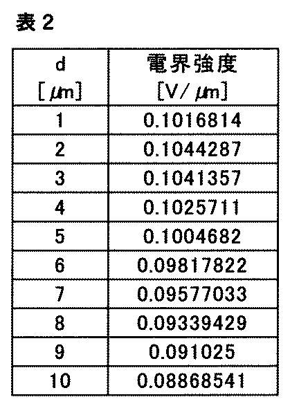
本開示の糸において、抵抗率は、例えば、絶縁抵抗計によって測定することができる。
尚、本開示の糸(又は抗菌糸)において、抗菌性がより確実に得られる物性およびその値(物性値)は、上記の「比誘電率」、「インピーダンス」、「抵抗率」に限定されるものではない。
[糸の用途]
本開示の糸は、電位発生フィラメント(又は電位発生繊維又は電荷発生繊維又は電場形成繊維)として、外部からのエネルギー(例えば少なくとも0.15%の引張り力または引張歪みなどの外部エネルギーを与えることなど)により電荷を発生して電位を発生することおよび電場を形成することができる繊維を有して成るため、糸の近傍に電場または電位が形成され、あるいは糸と糸との間、または人体等の所定の電位(グランド電位を含む)を有する物体に近接した場合などにも電場を生じさせることができる。上述の通り、このような電位または電場によって、直接的に抗菌性を発揮することができる。
本開示の糸は、電位発生フィラメント(又は電位発生繊維又は電荷発生繊維又は電場形成繊維)として、外部からのエネルギー(例えば少なくとも0.15%の引張り力または引張歪みなどの外部エネルギーを与えることなど)により電荷を発生して電位を発生することおよび電場を形成することができる繊維を有して成るため、糸の近傍に電場または電位が形成され、あるいは糸と糸との間、または人体等の所定の電位(グランド電位を含む)を有する物体に近接した場合などにも電場を生じさせることができる。上述の通り、このような電位または電場によって、直接的に抗菌性を発揮することができる。
また、本開示の糸は、汗等の水分を介して、近接する他の繊維または人体等の所定の電位を有する物体に近接した場合に電流を流すこともできる。この電流によっても、抗菌性を発揮する場合がある。
従って、本開示の糸は、例えば、人体等の所定の電位を有する物体に近接して用いられ得る物品に適用した場合、発生した電位もしくは電場または電流の作用、特に電位または電場の直接的な作用によって、上記のような抗菌性を発揮することができる。
本開示の糸を適用することができる物品または製品としては、特に制限されるわけではないが、例えば、衣料(全般)、履物(全般)、マスク等の医療用品(全般)などが挙げられる。より具体的には、以下の用途などが考えられる。
例えば、衣料全般、特に肌着(特に靴下)、タオル、履物全般、例えば、靴およびブーツ等の中敷き、スポーツウェア全般、帽子、寝具(布団、マットレス、シーツ、枕、枕カバー等を含む)、歯ブラシ、フロス、各種フィルタ類(浄水器、エアコンまたは空気清浄器などのフィルタ等)、ぬいぐるみ、ペット関連商品(ペット用マット、ペット用服、ペット用服のインナー)、各種マット品(足、手、または便座等)、カーテン、台所用品(スポンジまたは布巾等)、シート(車、電車または飛行機等のシート)、オートバイ用ヘルメットの緩衝材およびその外装材、ソファ、医療用品全般、例えば、包帯、ガーゼ、マスク、縫合糸、医者および患者の服、サポーター、サニタリ用品、スポーツ用品(ウェアおよびグローブのインナー、または武道で使用する籠手等)、あるいは包装資材等が挙げられる。
衣料のうち、特に靴下(またはサポーター)は、歩行等の動きによって、関節に沿って必ず伸縮が生じるため、本開示の糸は、高頻度で電荷または電位を発生することができる。また、靴下は、汗などの水分を吸い取り、菌などの増殖の温床となるが、本開示の糸は、菌の増殖を抑制することができるため、防臭のための菌対策用途として、顕著な効果を生じ得る。
尚、本開示の糸は、抗菌性が求められるあらゆる用途に適していると考えられ、その用途は、上記の用途に特に限定されるものではない。
(布)
本開示の糸は、例えば、上記用途のために、布に加工することができる。従って、このような布は、本開示の糸を含んで成るものであり、上記の抗菌性を有する「抗菌布」として、上記の用途などに使用することができる。本開示の布には、織物、編物、不織布などが含まれる。これらは、本開示の糸から、当該分野で周知の方法などによって、適切に加工することで製造することができる。
本開示の糸は、例えば、上記用途のために、布に加工することができる。従って、このような布は、本開示の糸を含んで成るものであり、上記の抗菌性を有する「抗菌布」として、上記の用途などに使用することができる。本開示の布には、織物、編物、不織布などが含まれる。これらは、本開示の糸から、当該分野で周知の方法などによって、適切に加工することで製造することができる。
以下、実施例により、本開示の糸および布について、さらに詳しく説明する。
<電気的刺激による抗菌作用を確認するための予備試験>
電気的刺激による抗菌作用を確認するための予備試験を以下の手順(1)~(4)に基づいて行った。
(1)菌として、白癬菌(真菌)を用いて、発芽管状態の白癬菌を純水中に懸濁させることで白癬菌の懸濁液を準備した。
(2)白癬菌の懸濁液に以下の各条件で電圧を印加した。
(3)電圧印加後の白癬菌の状態を[図8]の写真に示す。
(4)電圧印加前後における白癬菌の状態変化の代表例として、20V×5Hzおよび50V×5Hzについて、それぞれ[図9](a)および[図9](b)に白癬菌の状態変化の写真を示す。
電気的刺激による抗菌作用を確認するための予備試験を以下の手順(1)~(4)に基づいて行った。
(1)菌として、白癬菌(真菌)を用いて、発芽管状態の白癬菌を純水中に懸濁させることで白癬菌の懸濁液を準備した。
(2)白癬菌の懸濁液に以下の各条件で電圧を印加した。
(3)電圧印加後の白癬菌の状態を[図8]の写真に示す。
(4)電圧印加前後における白癬菌の状態変化の代表例として、20V×5Hzおよび50V×5Hzについて、それぞれ[図9](a)および[図9](b)に白癬菌の状態変化の写真を示す。
・電極間距離
50μm
・電圧
条件A:10V
条件B:20V
条件C:30V
条件D:40V
条件E:50V
・周波数
1Hz
5Hz
10Hz
・測定回数
n=3
50μm
・電圧
条件A:10V
条件B:20V
条件C:30V
条件D:40V
条件E:50V
・周波数
1Hz
5Hz
10Hz
・測定回数
n=3
(結果)
10Vから50Vにわたって10Vごとに電圧を変化させて電圧の値を増加させた(条件A~E)。その結果、電圧の増加にともなって白癬菌が変形し、原形質流動が停止する場合もあることが明らかとなった。[図9](a)および[図9](b)は、電圧印加前後における白癬菌の変形の代表写真であり、それぞれ胞子と菌糸の変形を確認した。特に、電圧条件DおよびEにおいて、白癬菌の原形質流動の停止を確認した。
その一方で、周波数を1Hz、5Hz、10Hzに変化させて、電流の値を増加させても、白癬菌の原形質流動が停止しない場合もあることがわかった。
以上のことから、抗菌作用には、電流の値よりも電圧の値が優位に関与することがわかった。
また、予備試験で使用した白癬菌の胞子の大きさは、[図10]の写真に示す通り、5μm程度であり、電界強度が約0.2V/μm以上の電圧を印加した場合には、胞子の端から端にわたって、約1.0V以上の電圧が印加され、白癬菌が死滅または減少することがわかった。
以上のことから、菌、特に真菌の胞子の大きさは、約2μm~10μm程度であることから(「食品衛生の窓」、東京都福祉保健局ホームページ)、上記の結果に基づいて、約0.1V/μm以上の電圧を印加すると、最大10μmの大きさの胞子にも対応して、約1.0V以上の電圧が印加され、このような菌を死滅または減少させることができることがわかる。
尚、上記の予備試験はあくまで例示であって、本発明を拘束することを意図するものではない。
(実施例1)
糸Aの準備
圧電材料としてポリ-L-乳酸(PLLA)を含む電位発生フィラメント(フィラメント数:24本)からなる糸Aを準備した(無撚糸)(高速液体クロマトグラフィー(HPLC)で測定し、算出した光学純度(L体):99%以上、株式会社リガク製 ultraX 18で測定した結晶化度:42~44%)。糸Aに含まれる電位発生フィラメントは、その周りに油剤を誘電体として含むものであった。尚、油剤は、糸の製造後の洗濯によって、電位発生フィラメントから、その一部が脱落していることがわかった。
糸Aの比誘電率の測定
糸Aの比誘電率は、平行板コンデンサーの間に糸Aを通して静電容量を測定し、糸Aを通していない時の静電容量との差分から糸Aの静電容量を算出し、その値と糸の容量を用いることによって、糸Aの誘電率を求め、さらに、真空の誘電率を用いて、式:[糸Aの比誘電率]=[糸Aの誘電率]/[真空の誘電率]に基づいて、計算により決定したところ、糸Aの比誘電率は、約1.4であることがわかった(測定温度:室温(25℃))。
糸Aにより形成される電場の電界強度の測定
糸AはPLLA(光学純度(L体):99%以上、結晶化度:42~44%)を含むことから、少なくとも0.15%の引張歪み等の外部からのエネルギーを与えることで電場または電位が発生することがわかった。また、糸Aの比誘電率が1.4であることから、糸Aにより形成される電場は、走査型プローブおよび表面電位計などを含む電気力顕微鏡(例えば、トレック社製 Model 1100TN)を用いて測定したところ、約0.1V/μmを超える電界強度を有することが分かった。
尚、電界強度の測定は、まず、走査型プローブを用いて、微弱な電圧を印加した微小なプローブを糸Aに近接させることによる電気引力あるいは斥力によるプローブの変位を検出し、次に、表面電位計を用いて、微小なプローブに加わった電気引力あるいは斥力を相殺するための電圧を測定することで糸Aの電界強度の値を測定した。
抗菌性
以上のことから、糸Aは、約0.1V/μmを超える電界強度を有することから、例えば10μm程度の白癬菌に対して、十分な抗菌性を示すことがわかった。
(実施例2)
糸Bの準備
圧電材料としてポリ-L-乳酸(PLLA)を含む電位発生フィラメント(フィラメント数:24本)からなる糸Bを準備した(無撚糸)(高速液体クロマトグラフィー(HPLC)で測定し、算出した光学純度(L体):99%以上、株式会社リガク製 ultraX 18で測定した結晶化度:42~44%)。糸Bに含まれる電位発生フィラメントは、その周りに帯電防止剤を誘電体として含むものであった。尚、帯電防止剤は、糸の製造後の洗濯によって、電位発生フィラメントから、その一部が脱落していることがわかった。
糸Bの比誘電率の測定
糸Bの比誘電率は、上記糸Aと同様に測定したところ、約1.4であることがわかった(測定温度:室温(25℃))。
糸Bにより形成される電場の電界強度の測定
糸BはPLLA(光学純度(L体):99%以上、結晶化度:42~44%)を含むことから、少なくとも0.15%の引張歪み等の外部からのエネルギーを与えることで電場または電位が発生することがわかった。また、糸Bの比誘電率が約1.4であることから、糸Bにより形成される電場は、上記糸Aと同様に測定したところ、約0.1V/μmを超える電界強度を有することが分かった。
抗菌性
以上のことから、糸Bは、約0.1V/μmを超える電界強度を有することから、例えば10μm程度の白癬菌に対して、十分な抗菌性を示すことがわかった。
(実施例3)
糸Cの準備
圧電材料としてポリ-L-乳酸(PLLA)を含む電位発生フィラメント(フィラメント数:24本)からなる糸Cを準備した(無撚糸)(高速液体クロマトグラフィー(HPLC)で測定し、算出した光学純度(L体):99%以上、株式会社リガク製 ultraX 18で測定した結晶化度:42~44%)。糸Cに含まれる電位発生フィラメントは、表面処理剤を全く含まず、その周りには誘電体として空気層のみが存在していた。
糸Cの比誘電率の測定
糸Cの比誘電率は、上記糸Aと同様に測定したところ、約1.1であることがわかった(測定温度:室温(25℃))。
糸Cにより形成される電場の電界強度の測定
糸CはPLLA(光学純度(L体):99%以上、結晶化度:42~44%)を含むことから、少なくとも0.15%の引張歪み等の外部からのエネルギーを与えることで電場または電位が発生することがわかった。また、糸Cの比誘電率が約1.1であることから、糸Cにより形成される電場は、上記糸Aと同様に測定したところ、約0.1V/μmを超える電界強度を有することが分かった。
抗菌性
以上のことから、糸Cは、約0.1V/μmを超える電界強度を有することから、例えば10μm程度の白癬菌に対して、十分な抗菌性を示すことがわかった。
(実施例4)
糸Dの準備
圧電材料としてポリ-L-乳酸(PLLA)からなる電位発生フィラメント(フィラメント数:24本)からなる糸Dを準備した(無撚糸、脱脂済)(高速液体クロマトグラフィー(HPLC)で測定し、算出した光学純度(L体):99%以上、株式会社リガク製 ultraX 18で測定した結晶化度:42~44%)。
糸Dの準備
圧電材料としてポリ-L-乳酸(PLLA)からなる電位発生フィラメント(フィラメント数:24本)からなる糸Dを準備した(無撚糸、脱脂済)(高速液体クロマトグラフィー(HPLC)で測定し、算出した光学純度(L体):99%以上、株式会社リガク製 ultraX 18で測定した結晶化度:42~44%)。
糸Dの糸束での比誘電率の測定
糸Dをボビンにセットし、村田製作所製の糸巻き機を用いて、直径45mmの巻取り筒に糸Dが厚み方向に重ならないように糸道ガイドを通して糸Dを横方向に整列させて筒上に糸Dを巻き取った(回転速度:60rpm、1分間)(図11(A)参照)。
巻取り筒の軸方向に沿って糸Dをカットすることで巻取り筒から糸Dを切り離して約1cm幅の糸束サンプル(糸D)を得た(図11(B)参照)。尚、糸束サンプルの長手方向の上下の両端部はカットする際に固定した。
糸サンプル(糸D)をジグ(万力)にセットしてカプトン(登録商標)テープで固定した(図12(A)参照(写真は測定方法の例を示すに過ぎず糸束サンプルに含まれる糸は糸Dとは異なる))。
フィクスチャ(Agilent社製のDielectric Test Fixture(型番:16451B))に接続されたLCRメータ(Agilent社製のPrecision LCR Meter(型番:E4980A))の2枚の円形の測定用電極の間に糸束サンプル(糸D)を重ねて配置し(厚さ:約50μm)、2枚の測定用電極で糸束サンプルを挟んで固定した(図12(B)参照(写真は測定方法の例を示すに過ぎず糸束サンプルに含まれる糸は糸Dとは異なる))。
ここでLCRメータの測定用電極と糸束サンプルとの関係を図13に示す。この模式図で示す糸束サンプルの場合、糸Dが測定用電極に挟まれて互いに隣接していることから、糸Dと糸Dとの間には空隙が存在しないと仮定した。
図13に示す面積S1とS2の和を4倍したものを糸束サンプルの面積として計算した(以下、「サンプル面積」と称する)。
このようなサンプル面積にわたってLCRメータで糸Dの比誘電率を測定した結果、その値は約2.1であった(温度:室温(25℃)、周波数:1kHz)。測定の詳細については以下の表3に示す。
(実施例5)
糸Eの準備
圧電材料としてポリ-L-乳酸(PLLA)からなる電位発生フィラメント(フィラメント数:24本)からなる糸Eを準備した(無撚糸、脱脂済)(高速液体クロマトグラフィー(HPLC)で測定し、算出した光学純度(L体):99%以上、株式会社リガク製 ultraX 18で測定した結晶化度:42~44%)。
糸Eの準備
圧電材料としてポリ-L-乳酸(PLLA)からなる電位発生フィラメント(フィラメント数:24本)からなる糸Eを準備した(無撚糸、脱脂済)(高速液体クロマトグラフィー(HPLC)で測定し、算出した光学純度(L体):99%以上、株式会社リガク製 ultraX 18で測定した結晶化度:42~44%)。
糸Eの糸束での比誘電率の測定
実施例4の糸Dと同様にして糸Eの比誘電率をLCRメータで測定した結果、比誘電率の値は約1.9であった。測定の詳細については以下の表3に示す。
実施例4の糸Dと同様にして糸Eの比誘電率をLCRメータで測定した結果、比誘電率の値は約1.9であった。測定の詳細については以下の表3に示す。
(実施例6)
糸Fの準備
圧電材料としてポリ-L-乳酸(PLLA)からなる電位発生フィラメント(フィラメント数:24本)からなる糸を準備した(無撚糸)(高速液体クロマトグラフィー(HPLC)で測定し、算出した光学純度(L体):99%以上、株式会社リガク製 ultraX 18で測定した結晶化度:42~44%)。
上記の糸に約0.1mLの表面処理剤(ナイスポールPR-99(日華化学株式会社製のナイスポール・シリーズ)、PEG変性ポリエステル系ポリマーを含む帯電防止剤)を塗布して乾燥させることで糸F(無撚糸)を準備した(塗布前重量:0.207g、塗布後乾燥重量:0.219g、付着重量:0.012g、付着量:5.4重量%)。
糸Fの糸束での比誘電率の測定
実施例4と同様にして糸Fの糸束サンプルを準備した(図11参照)。
糸束サンプル(糸F)をジグ(万力)にセットしてカプトン(登録商標)テープで固定した(図12(A)参照(写真は測定方法の例を示すに過ぎず糸束サンプルに含まれる糸は糸Fとは異なる))。
実施例4と同様にしてフィクスチャ(Agilent社製のDielectric Test Fixture(型番:16451B))に接続されたLCRメータ(Agilent社製のPrecision LCR Meter(型番:E4980A))の2枚の円形の測定用電極の間に糸束サンプル(糸F)を重ねて配置し(厚さ:約50μm)、糸束サンプルを2枚の測定用電極で挟むことで固定した(図12(B)参照(写真は測定方法の例を示すに過ぎず糸束サンプルに含まれる糸は糸Fとは異なる))。
この糸束サンプルの場合、糸Fには表面処理剤が塗布されていることから糸に含まれるフィラメントが集合して糸Fと糸Fとの間に空間が生じた。
このような場合、例えば図13に示す面積S1とS2の和を4倍した値(換言すると理想的な状態の面積の値)から空間の面積を引き算したものをサンプル面積として計算した。尚、この空間の面積は、糸Fと糸Fの間の間隔を実際に測定し、好ましくは隙間合計の平均として算出し、測定用電極に配置された幅1cmの糸束サンプル(図13参照)の幅方向(電極直径方向)にわたって積算することで算出した。
このようなサンプル面積にわたってLCRメータで糸Fの比誘電率を測定した結果、その値は約4.5であった(温度:室温(25℃)、周波数:1kHz)。測定の詳細については以下の表4に示す。
(実施例7)
糸Gの準備
圧電材料としてポリ-L-乳酸(PLLA)からなる電位発生フィラメント(フィラメント数:24本)からなる糸を準備した(無撚糸)(高速液体クロマトグラフィー(HPLC)で測定し、算出した光学純度(L体):99%以上、株式会社リガク製 ultraX 18で測定した結晶化度:42~44%)。
上記の糸に約0.1mLの表面処理剤(SR-1800(高松油脂株式会社製のSR加工剤・吸水加工剤・シリーズ)、ポリエステル系ポリマーを含む吸水性・SR性(汚れ除去性または防汚性)・帯電防止効果を付与することができる表面処理剤)を塗布して乾燥させることで糸G(無撚糸)を準備した(塗布前重量:0.203g、塗布後乾燥重量:0.213g、付着重量:0.010g、付着量:4.7重量%)。
糸Gの糸束での比誘電率の測定
実施例6の糸Fと同様にして糸Gの比誘電率をLCRメータで測定した結果、比誘電率の値は約4.5であった。測定の詳細については以下の表4に示す。
実施例6の糸Fと同様にして糸Gの比誘電率をLCRメータで測定した結果、比誘電率の値は約4.5であった。測定の詳細については以下の表4に示す。
(実施例8)
糸Hの準備
圧電材料としてポリ-L-乳酸(PLLA)からなる電位発生フィラメント(フィラメント数:24本)からなる糸を準備した(無撚糸)(高速液体クロマトグラフィー(HPLC)で測定し、算出した光学純度(L体):99%以上、株式会社リガク製 ultraX 18で測定した結晶化度:42~44%)。
上記の糸に約0.1mLの表面処理剤(クインスタット(QUEENSTAT)NW-E conc(コタニ化学工業株式会社製クインスタット・シリーズ)、架橋性親水ウレタン系ポリマーを含む吸水性・SR性(汚れ除去性または防汚性)・帯電防止効果を付与することができる表面処理剤)を塗布して乾燥させることで糸H(無撚糸)を準備した(塗布前重量:0.205g、塗布後乾燥重量:0.234g、付着重量:0.029g、付着量:12重量%)。
糸Hの糸束での比誘電率の測定
実施例6の糸Fと同様にして糸Hの比誘電率をLCRメータで測定した結果、比誘電率の値は約4.4であった。測定の詳細については以下の表4に示す。
実施例6の糸Fと同様にして糸Hの比誘電率をLCRメータで測定した結果、比誘電率の値は約4.4であった。測定の詳細については以下の表4に示す。
(実施例9)
糸Iの準備
圧電材料としてポリ-L-乳酸(PLLA)からなる電位発生フィラメント(フィラメント数:24本)からなる糸を準備した(無撚糸)(高速液体クロマトグラフィー(HPLC)で測定し、算出した光学純度(L体):99%以上、株式会社リガク製 ultraX 18で測定した結晶化度:42~44%)。
上記の糸に約0.1mLの金属酸化物を含む液体(酸化チタン(TiO2)スプレー液(TRUSCO(トラスコ)中山株式会社製の光触媒TiO2抗菌・消臭スプレー))を塗布して乾燥させることで糸I(無撚糸)を準備した(塗布前重量:0.206g、塗布後乾燥重量:0.207g、付着重量:0.001g、付着量:0.48重量%)。
糸Iの糸束での比誘電率の測定
実施例6の糸Fと同様にして糸Iの比誘電率をLCRメータで測定した結果、比誘電率の値は約3.3であった。測定の詳細については以下の表5に示す。
実施例6の糸Fと同様にして糸Iの比誘電率をLCRメータで測定した結果、比誘電率の値は約3.3であった。測定の詳細については以下の表5に示す。
(実施例10)
糸Jの準備
圧電材料としてポリ-L-乳酸(PLLA)からなる電位発生フィラメント(フィラメント数:24本)からなる糸を準備した(無撚糸)(高速液体クロマトグラフィー(HPLC)で測定し、算出した光学純度(L体):99%以上、株式会社リガク製 ultraX 18で測定した結晶化度:42~44%)。
上記の糸に約0.1mLの金属酸化物を含む液体(酸化チタン(TiO2)スプレー液(TRUSCO(トラスコ)中山株式会社製の光触媒TiO2抗菌・消臭スプレー))を塗布して乾燥させることで糸J(無撚糸)を準備した(塗布前重量:0.213g、塗布後乾燥重量:0.213g、付着重量:0.001g未満、付着量:0.47重量%未満)。
糸Jの糸束での比誘電率の測定
実施例6の糸Fと同様にして糸Jの比誘電率をLCRメータで測定した結果、比誘電率の値は約3.5であった。測定の詳細については以下の表5に示す。
実施例6の糸Fと同様にして糸Jの比誘電率をLCRメータで測定した結果、比誘電率の値は約3.5であった。測定の詳細については以下の表5に示す。


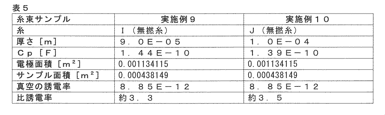
糸D~Jにより形成される電場の電界強度の測定
糸D~JはPLLA(光学純度(L体):99%以上、結晶化度:42~44%)を含むことから、少なくとも0.15%の引張り力または引張歪みなどの外部エネルギーを与えることで電場が発生する。また、糸D~Jは約4.5以下の比誘電率を有することから、糸D~Jにより形成される電場は、上記糸A~Cと同様に約0.1V/μmを超える電界強度を有することが分かった。
抗菌性
以上のことから、糸D~Jは、約0.1V/μmを超える電界強度を有し、約10μm程度の白癬菌に対して、十分な抗菌性を示すことがわかった。
糸D~JはPLLA(光学純度(L体):99%以上、結晶化度:42~44%)を含むことから、少なくとも0.15%の引張り力または引張歪みなどの外部エネルギーを与えることで電場が発生する。また、糸D~Jは約4.5以下の比誘電率を有することから、糸D~Jにより形成される電場は、上記糸A~Cと同様に約0.1V/μmを超える電界強度を有することが分かった。
抗菌性
以上のことから、糸D~Jは、約0.1V/μmを超える電界強度を有し、約10μm程度の白癬菌に対して、十分な抗菌性を示すことがわかった。
尚、実施例1の糸Aおよび実施例2の糸Bについて実施例6の糸Fと同様に糸束として比誘電率を測定した結果、比誘電率はそれぞれ約1.4であり、上記の実施例1および2で測定した結果と一致することがわかった。
また、実施例3の糸Cについて実施例4の糸Dと同様に糸束として比誘電率を測定した結果、糸Cの比誘電率は約1.1であり、上記の実施例3で測定した結果と一致することがわかった。
また、実施例3の糸Cについて実施例4の糸Dと同様に糸束として比誘電率を測定した結果、糸Cの比誘電率は約1.1であり、上記の実施例3で測定した結果と一致することがわかった。
(比較例1)
非圧電ポリ乳酸(PLA)ポリマー(ユニチカ製のテラマック(登録商標)(TERRAMAC)、結晶化度:34%)は、圧電性を有していないことから、電荷を発生することがなく、抗菌性も示さないことがわかった。
非圧電ポリ乳酸(PLA)ポリマー(ユニチカ製のテラマック(登録商標)(TERRAMAC)、結晶化度:34%)は、圧電性を有していないことから、電荷を発生することがなく、抗菌性も示さないことがわかった。
上記の実施例1~10は、本開示の糸を例示するに過ぎず、特に比誘電率および発生する電位などを調節することができることを例示するに過ぎず、本開示の糸は、上記の実施例に示す形態に限定されるものではない。また、実施例1~10は、いずれも無撚糸であるが、撚りをかけることによって(例えば45°)、電界強度をさらに高めること、ひいてはさらに抗菌性を高めることができる。
最後に本発明の態様について付言的に述べておく。上述した本発明は、限定されないものの以下の態様を含んでいる。
(態様1)
電位発生フィラメントまたは電場形成フィラメントを有して成る糸であって、前記糸の比誘電率が4.5以下であることを特徴とする糸。
(態様2)
前記比誘電率が1.0以上であることを特徴とする、態様1に記載の糸。
(態様3)
前記糸のインピーダンスが4.0×10⁶Ωm以上であることを特徴とする、態様1または2に記載の糸。
(態様4)
前記インピーダンスが1.8×10⁷Ωm以下であることを特徴とする、態様3に記載の糸。
(態様5)
前記糸の抵抗率が1.4×10⁴Ωm以上であることを特徴とする、態様1~4のいずれか1項に記載の糸。
(態様6)
前記抵抗率が2.3×10¹⁵Ωm以下であることを特徴とする、態様5に記載の糸。
(態様7)
前記電位発生フィラメントが圧電材料を含んで成ることを特徴とする、態様1~6のいずれか1項に記載の糸。
(態様8)
前記圧電材料がポリ-L-乳酸(PLLA)を含んで成ることを特徴とする、態様7に記載の糸。
(態様9)
前記ポリ-L-乳酸(PLLA)の結晶化度が35%以上である、態様8に記載の糸。
(態様10)
前記電位発生フィラメントの周りの少なくとも一部に誘電体が設けられていることを特徴とする、態様1~9のいずれか1項に記載の糸。
(態様11)
前記誘電体が油剤を含んで成ることを特徴とする、態様10に記載の糸。
(態様12)
前記誘電体が導電性を有することを特徴とする、態様10または11に記載の糸。
(態様13)
前記誘電体が帯電防止剤を含んで成ることを特徴とする、態様10~12のいずれか1項に記載の糸。
(態様14)
前記誘電体が空気を含んで成ることを特徴とする、態様10に記載の糸。
(態様15)
前記誘電体がポリマーを含んで成ることを特徴とする、態様10に記載の糸。
(態様16)
前記ポリマーがエステル系ポリマーおよびウレタン系ポリマーからなる群から選択される少なくとも一種を含んで成ることを特徴とする、態様15に記載の糸。
(態様17)
前記誘電体が金属酸化物を含んで成ることを特徴とする、態様10に記載の糸。
(態様18)
前記金属酸化物が酸化チタンであることを特徴とする、態様17に記載の糸。
(態様19)
前記糸が表面処理剤を含まないことを特徴とする、態様1~9のいずれか1項に記載の糸。
(態様20)
前記糸が抗菌糸であることを特徴とする、態様1~19のいずれか1項に記載の糸。
(態様21)
態様1~20のいずれか1項に記載の糸を含んで成ることを特徴とする布。
本発明は、様々な製品に利用することができる。例えば、糸が使用される日用製品、工業製品、特に衣料製品の全般において、糸または布として好適に用いることができる。
1,2: 糸
10: 電位発生フィラメント(又は電場形成フィラメント)
100: 誘電体
900: 延伸方向
910A: 第1対角線
910B: 第2対角線
10: 電位発生フィラメント(又は電場形成フィラメント)
100: 誘電体
900: 延伸方向
910A: 第1対角線
910B: 第2対角線
Claims (21)
- 電位発生フィラメントを有して成る糸であって、前記糸の比誘電率が4.5以下であることを特徴とする糸。
- 前記比誘電率が1.0以上であることを特徴とする、請求項1に記載の糸。
- 前記糸のインピーダンスが4.0×10⁶Ωm以上であることを特徴とする、請求項1または2に記載の糸。
- 前記インピーダンスが1.8×10⁷Ωm以下であることを特徴とする、請求項3に記載の糸。
- 前記糸の抵抗率が1.4×10⁴Ωm以上であることを特徴とする、請求項1~4のいずれか1項に記載の糸。
- 前記抵抗率が2.3×10¹⁵Ωm以下であることを特徴とする、請求項5に記載の糸。
- 前記電位発生フィラメントが圧電材料を含んで成ることを特徴とする、請求項1~6のいずれか1項に記載の糸。
- 前記圧電材料がポリ-L-乳酸(PLLA)を含んで成ることを特徴とする、請求項7に記載の糸。
- 前記ポリ-L-乳酸(PLLA)の結晶化度が35%以上である、請求項8に記載の糸。
- 前記電位発生フィラメントの周りの少なくとも一部に誘電体が設けられていることを特徴とする、請求項1~9のいずれか1項に記載の糸。
- 前記誘電体が油剤を含んで成ることを特徴とする、請求項10に記載の糸。
- 前記誘電体が導電性を有することを特徴とする、請求項10または11に記載の糸。
- 前記誘電体が帯電防止剤を含んで成ることを特徴とする、請求項10~12のいずれか1項に記載の糸。
- 前記誘電体が空気を含んで成ることを特徴とする、請求項10に記載の糸。
- 前記誘電体がポリマーを含んで成ることを特徴とする、請求項10に記載の糸。
- 前記ポリマーがエステル系ポリマーおよびウレタン系ポリマーからなる群から選択される少なくとも一種を含んで成ることを特徴とする、請求項15に記載の糸。
- 前記誘電体が金属酸化物を含んで成ることを特徴とする、請求項10に記載の糸。
- 前記金属酸化物が酸化チタンであることを特徴とする、請求項17に記載の糸。
- 前記糸が表面処理剤を含まないことを特徴とする、請求項1~9のいずれか1項に記載の糸。
- 前記糸が抗菌糸であることを特徴とする、請求項1~19のいずれか1項に記載の糸。
- 請求項1~20のいずれか1項に記載の糸を含んで成ることを特徴とする布。
Priority Applications (4)
| Application Number | Priority Date | Filing Date | Title |
|---|---|---|---|
| JP2021570089A JP7431256B2 (ja) | 2020-01-08 | 2021-01-07 | 糸および布 |
| EP21738573.1A EP4071284A4 (en) | 2020-01-08 | 2021-01-07 | YARN AND FABRIC |
| CN202180008141.6A CN114929956A (zh) | 2020-01-08 | 2021-01-07 | 纱线和布 |
| US17/857,406 US20220364277A1 (en) | 2020-01-08 | 2022-07-05 | Yarn and fabric |
Applications Claiming Priority (2)
| Application Number | Priority Date | Filing Date | Title |
|---|---|---|---|
| JP2020-001614 | 2020-01-08 | ||
| JP2020001614 | 2020-01-08 |
Related Child Applications (1)
| Application Number | Title | Priority Date | Filing Date |
|---|---|---|---|
| US17/857,406 Continuation US20220364277A1 (en) | 2020-01-08 | 2022-07-05 | Yarn and fabric |
Publications (1)
| Publication Number | Publication Date |
|---|---|
| WO2021141089A1 true WO2021141089A1 (ja) | 2021-07-15 |
Family
ID=76788627
Family Applications (1)
| Application Number | Title | Priority Date | Filing Date |
|---|---|---|---|
| PCT/JP2021/000385 WO2021141089A1 (ja) | 2020-01-08 | 2021-01-07 | 糸および布 |
Country Status (5)
| Country | Link |
|---|---|
| US (1) | US20220364277A1 (ja) |
| EP (1) | EP4071284A4 (ja) |
| JP (1) | JP7431256B2 (ja) |
| CN (1) | CN114929956A (ja) |
| WO (1) | WO2021141089A1 (ja) |
Citations (13)
| Publication number | Priority date | Publication date | Assignee | Title |
|---|---|---|---|---|
| JPH0128979B2 (ja) | 1982-10-11 | 1989-06-07 | Fujitsu Ltd | |
| JPH07310284A (ja) | 1994-05-12 | 1995-11-28 | Toray Ind Inc | 抗菌性繊維構造物 |
| JPH08226078A (ja) | 1995-02-21 | 1996-09-03 | Teisan Seiyaku Kk | 抗菌剤含有ナイロン繊維およびその製造法 |
| JPH09194304A (ja) | 1996-01-17 | 1997-07-29 | Daisutaa Japan Kk | 繊維の抗菌処理方法 |
| JP2001040529A (ja) * | 1999-05-21 | 2001-02-13 | Shimadzu Corp | モノフィラメント及びその製造方法 |
| JP3165992B2 (ja) | 1995-03-14 | 2001-05-14 | 東レ株式会社 | 抗菌性樹脂とその製造方法及び抗菌性繊維構造物 |
| JP3281640B2 (ja) | 1992-06-01 | 2002-05-13 | 東レ株式会社 | 抗菌性繊維構造物の製造方法及びその抗菌性繊維構造物 |
| JP2004300650A (ja) | 2003-03-20 | 2004-10-28 | Toray Ind Inc | 抗白癬菌性を有する繊維材料 |
| JP3805853B2 (ja) | 1997-03-13 | 2006-08-09 | 株式会社メニコン | 重合性色素及びそれを用いた着色眼用レンズ材料 |
| JP2006225821A (ja) * | 2005-02-15 | 2006-08-31 | Kurosawa Lace:Kk | ポリ乳酸繊維構造物 |
| JP2009013553A (ja) * | 2007-06-08 | 2009-01-22 | Takemoto Oil & Fat Co Ltd | 合成繊維用ストレート型処理剤、これを用いる合成繊維仮撚加工糸の処理方法及び合成繊維仮撚加工糸 |
| WO2018211817A1 (ja) * | 2017-05-19 | 2018-11-22 | 株式会社村田製作所 | 抗菌繊維、シート、およびシートカバー |
| WO2018221332A1 (ja) * | 2017-05-30 | 2018-12-06 | 帝人フロンティア株式会社 | 菌対策用電荷発生糸、菌対策用電荷発生糸の製造方法、および抗菌性布帛 |
Family Cites Families (10)
| Publication number | Priority date | Publication date | Assignee | Title |
|---|---|---|---|---|
| DE60018635T2 (de) * | 1999-05-21 | 2006-04-13 | Toyota Jidosha K.K., Toyota | Monofilament und Verfahren zu seiner Herstellung |
| WO2012026494A1 (ja) * | 2010-08-25 | 2012-03-01 | 三井化学株式会社 | 高分子圧電材料、およびその製造方法 |
| JP2012121995A (ja) * | 2010-12-08 | 2012-06-28 | Hitachi Cable Ltd | 樹脂組成物及び発泡絶縁電線 |
| KR101402066B1 (ko) * | 2012-10-31 | 2014-06-02 | 이규환 | 나선형 코일사와 그 섬유원단, 및 그의 제조방법 |
| CN108701753B (zh) * | 2015-12-25 | 2023-06-27 | 三井化学株式会社 | 压电基材、压电机织物、压电针织物及压电装置 |
| WO2017212523A1 (ja) * | 2016-06-06 | 2017-12-14 | 株式会社村田製作所 | 菌対策用圧電糸、菌対策用布、布、衣料、医療部材、生体作用圧電糸、および物質吸着用圧電糸 |
| US11479647B2 (en) * | 2016-09-28 | 2022-10-25 | Daikin Industries. Ltd. | Film including a fluoropolymer |
| JP6573040B2 (ja) * | 2016-12-20 | 2019-09-11 | 株式会社村田製作所 | 抗菌繊維 |
| WO2019069660A1 (ja) | 2017-10-05 | 2019-04-11 | 株式会社村田製作所 | 圧電繊維 |
| CN110088367B (zh) * | 2017-10-17 | 2022-06-28 | 株式会社村田制作所 | 抗菌纱线和抗菌织物 |
-
2021
- 2021-01-07 CN CN202180008141.6A patent/CN114929956A/zh active Pending
- 2021-01-07 WO PCT/JP2021/000385 patent/WO2021141089A1/ja unknown
- 2021-01-07 EP EP21738573.1A patent/EP4071284A4/en active Pending
- 2021-01-07 JP JP2021570089A patent/JP7431256B2/ja active Active
-
2022
- 2022-07-05 US US17/857,406 patent/US20220364277A1/en active Pending
Patent Citations (13)
| Publication number | Priority date | Publication date | Assignee | Title |
|---|---|---|---|---|
| JPH0128979B2 (ja) | 1982-10-11 | 1989-06-07 | Fujitsu Ltd | |
| JP3281640B2 (ja) | 1992-06-01 | 2002-05-13 | 東レ株式会社 | 抗菌性繊維構造物の製造方法及びその抗菌性繊維構造物 |
| JPH07310284A (ja) | 1994-05-12 | 1995-11-28 | Toray Ind Inc | 抗菌性繊維構造物 |
| JPH08226078A (ja) | 1995-02-21 | 1996-09-03 | Teisan Seiyaku Kk | 抗菌剤含有ナイロン繊維およびその製造法 |
| JP3165992B2 (ja) | 1995-03-14 | 2001-05-14 | 東レ株式会社 | 抗菌性樹脂とその製造方法及び抗菌性繊維構造物 |
| JPH09194304A (ja) | 1996-01-17 | 1997-07-29 | Daisutaa Japan Kk | 繊維の抗菌処理方法 |
| JP3805853B2 (ja) | 1997-03-13 | 2006-08-09 | 株式会社メニコン | 重合性色素及びそれを用いた着色眼用レンズ材料 |
| JP2001040529A (ja) * | 1999-05-21 | 2001-02-13 | Shimadzu Corp | モノフィラメント及びその製造方法 |
| JP2004300650A (ja) | 2003-03-20 | 2004-10-28 | Toray Ind Inc | 抗白癬菌性を有する繊維材料 |
| JP2006225821A (ja) * | 2005-02-15 | 2006-08-31 | Kurosawa Lace:Kk | ポリ乳酸繊維構造物 |
| JP2009013553A (ja) * | 2007-06-08 | 2009-01-22 | Takemoto Oil & Fat Co Ltd | 合成繊維用ストレート型処理剤、これを用いる合成繊維仮撚加工糸の処理方法及び合成繊維仮撚加工糸 |
| WO2018211817A1 (ja) * | 2017-05-19 | 2018-11-22 | 株式会社村田製作所 | 抗菌繊維、シート、およびシートカバー |
| WO2018221332A1 (ja) * | 2017-05-30 | 2018-12-06 | 帝人フロンティア株式会社 | 菌対策用電荷発生糸、菌対策用電荷発生糸の製造方法、および抗菌性布帛 |
Non-Patent Citations (4)
| Title |
|---|
| "A Study of Mechanism of High Piezoelectric Performance Poly(lactic acid) Film Manufactured by Solid-State Extrusion", JOURNAL OF THE INSTITUTE OF ELECTROSTATICS JAPAN, vol. 40, no. 1, 2016, pages 38 - 43 |
| KOICHI TAKAKI: "Agricultural and Food Processing Applications of High-Voltage and Plasma Technologies", J. HTSJ, vol. 51, no. 216 |
| See also references of EP4071284A4 |
| TETSUAKI TSUCHIDOHIROKI KOURAIHIDEAKI MATSUOKAJUNICHI KOIZUMI, MICROBIAL CONTROL-SCIENCE AND ENGINEERING, pages 469 |
Also Published As
| Publication number | Publication date |
|---|---|
| JPWO2021141089A1 (ja) | 2021-07-15 |
| JP7431256B2 (ja) | 2024-02-14 |
| EP4071284A1 (en) | 2022-10-12 |
| US20220364277A1 (en) | 2022-11-17 |
| EP4071284A4 (en) | 2024-01-10 |
| CN114929956A (zh) | 2022-08-19 |
Similar Documents
| Publication | Publication Date | Title |
|---|---|---|
| JP6292368B1 (ja) | 布、衣料、医療部材、生体作用布、物質吸着用布、および菌対策用布 | |
| JP6428979B1 (ja) | 抗菌糸、シート、およびシートカバー | |
| JP6880180B2 (ja) | 菌対策用電荷発生糸、菌対策用電荷発生糸の製造方法、および抗菌性布帛 | |
| US20190281820A1 (en) | Antibacterial fiber | |
| JP2024045680A (ja) | 電位発生繊維を含む糸の表面電位の測定方法 | |
| US11946172B2 (en) | Antibacterial twisted yarn, and antibacterial yarn and antibacterial cloth including antibacterial twisted yarns | |
| WO2021141089A1 (ja) | 糸および布 | |
| WO2021200075A1 (ja) | 糸およびそれを含んで成る構造物 | |
| JP6784334B2 (ja) | 抗菌糸及び抗菌繊維製品 | |
| WO2020111049A1 (ja) | 抗菌撚糸、並びに抗菌撚糸を備える抗菌糸及び抗菌布 | |
| WO2022071336A1 (ja) | 布および繊維製品 |
Legal Events
| Date | Code | Title | Description |
|---|---|---|---|
| 121 | Ep: the epo has been informed by wipo that ep was designated in this application |
Ref document number: 21738573 Country of ref document: EP Kind code of ref document: A1 |
|
| ENP | Entry into the national phase |
Ref document number: 2021570089 Country of ref document: JP Kind code of ref document: A |
|
| ENP | Entry into the national phase |
Ref document number: 2021738573 Country of ref document: EP Effective date: 20220705 |
|
| NENP | Non-entry into the national phase |
Ref country code: DE |