WO2021140887A1 - 算出方法、軸受装置及び工作機械の主軸装置 - Google Patents
算出方法、軸受装置及び工作機械の主軸装置 Download PDFInfo
- Publication number
- WO2021140887A1 WO2021140887A1 PCT/JP2020/047578 JP2020047578W WO2021140887A1 WO 2021140887 A1 WO2021140887 A1 WO 2021140887A1 JP 2020047578 W JP2020047578 W JP 2020047578W WO 2021140887 A1 WO2021140887 A1 WO 2021140887A1
- Authority
- WO
- WIPO (PCT)
- Prior art keywords
- bearing
- rotating member
- displacement
- rotating
- housing
- Prior art date
- Legal status (The legal status is an assumption and is not a legal conclusion. Google has not performed a legal analysis and makes no representation as to the accuracy of the status listed.)
- Ceased
Links
Images


Classifications
-
- G—PHYSICS
- G01—MEASURING; TESTING
- G01B—MEASURING LENGTH, THICKNESS OR SIMILAR LINEAR DIMENSIONS; MEASURING ANGLES; MEASURING AREAS; MEASURING IRREGULARITIES OF SURFACES OR CONTOURS
- G01B7/00—Measuring arrangements characterised by the use of electric or magnetic techniques
- G01B7/14—Measuring arrangements characterised by the use of electric or magnetic techniques for measuring distance or clearance between spaced objects or spaced apertures
- G01B7/144—Measuring play on bearings
-
- F—MECHANICAL ENGINEERING; LIGHTING; HEATING; WEAPONS; BLASTING
- F16—ENGINEERING ELEMENTS AND UNITS; GENERAL MEASURES FOR PRODUCING AND MAINTAINING EFFECTIVE FUNCTIONING OF MACHINES OR INSTALLATIONS; THERMAL INSULATION IN GENERAL
- F16C—SHAFTS; FLEXIBLE SHAFTS; ELEMENTS OR CRANKSHAFT MECHANISMS; ROTARY BODIES OTHER THAN GEARING ELEMENTS; BEARINGS
- F16C19/00—Bearings with rolling contact, for exclusively rotary movement
- F16C19/52—Bearings with rolling contact, for exclusively rotary movement with devices affected by abnormal or undesired conditions
- F16C19/522—Bearings with rolling contact, for exclusively rotary movement with devices affected by abnormal or undesired conditions related to load on the bearing, e.g. bearings with load sensors or means to protect the bearing against overload
-
- F—MECHANICAL ENGINEERING; LIGHTING; HEATING; WEAPONS; BLASTING
- F16—ENGINEERING ELEMENTS AND UNITS; GENERAL MEASURES FOR PRODUCING AND MAINTAINING EFFECTIVE FUNCTIONING OF MACHINES OR INSTALLATIONS; THERMAL INSULATION IN GENERAL
- F16C—SHAFTS; FLEXIBLE SHAFTS; ELEMENTS OR CRANKSHAFT MECHANISMS; ROTARY BODIES OTHER THAN GEARING ELEMENTS; BEARINGS
- F16C41/00—Other accessories, e.g. devices integrated in the bearing not relating to the bearing function as such
-
- F—MECHANICAL ENGINEERING; LIGHTING; HEATING; WEAPONS; BLASTING
- F16—ENGINEERING ELEMENTS AND UNITS; GENERAL MEASURES FOR PRODUCING AND MAINTAINING EFFECTIVE FUNCTIONING OF MACHINES OR INSTALLATIONS; THERMAL INSULATION IN GENERAL
- F16C—SHAFTS; FLEXIBLE SHAFTS; ELEMENTS OR CRANKSHAFT MECHANISMS; ROTARY BODIES OTHER THAN GEARING ELEMENTS; BEARINGS
- F16C43/00—Assembling bearings
- F16C43/04—Assembling rolling-contact bearings
-
- G—PHYSICS
- G01—MEASURING; TESTING
- G01B—MEASURING LENGTH, THICKNESS OR SIMILAR LINEAR DIMENSIONS; MEASURING ANGLES; MEASURING AREAS; MEASURING IRREGULARITIES OF SURFACES OR CONTOURS
- G01B7/00—Measuring arrangements characterised by the use of electric or magnetic techniques
- G01B7/12—Measuring arrangements characterised by the use of electric or magnetic techniques for measuring diameters
- G01B7/125—Measuring arrangements characterised by the use of electric or magnetic techniques for measuring diameters of objects while moving
-
- G—PHYSICS
- G01—MEASURING; TESTING
- G01B—MEASURING LENGTH, THICKNESS OR SIMILAR LINEAR DIMENSIONS; MEASURING ANGLES; MEASURING AREAS; MEASURING IRREGULARITIES OF SURFACES OR CONTOURS
- G01B7/00—Measuring arrangements characterised by the use of electric or magnetic techniques
- G01B7/16—Measuring arrangements characterised by the use of electric or magnetic techniques for measuring the deformation in a solid, e.g. by resistance strain gauge
-
- G—PHYSICS
- G01—MEASURING; TESTING
- G01M—TESTING STATIC OR DYNAMIC BALANCE OF MACHINES OR STRUCTURES; TESTING OF STRUCTURES OR APPARATUS, NOT OTHERWISE PROVIDED FOR
- G01M13/00—Testing of machine parts
- G01M13/04—Bearings
-
- F—MECHANICAL ENGINEERING; LIGHTING; HEATING; WEAPONS; BLASTING
- F16—ENGINEERING ELEMENTS AND UNITS; GENERAL MEASURES FOR PRODUCING AND MAINTAINING EFFECTIVE FUNCTIONING OF MACHINES OR INSTALLATIONS; THERMAL INSULATION IN GENERAL
- F16C—SHAFTS; FLEXIBLE SHAFTS; ELEMENTS OR CRANKSHAFT MECHANISMS; ROTARY BODIES OTHER THAN GEARING ELEMENTS; BEARINGS
- F16C2233/00—Monitoring condition, e.g. temperature, load, vibration
-
- F—MECHANICAL ENGINEERING; LIGHTING; HEATING; WEAPONS; BLASTING
- F16—ENGINEERING ELEMENTS AND UNITS; GENERAL MEASURES FOR PRODUCING AND MAINTAINING EFFECTIVE FUNCTIONING OF MACHINES OR INSTALLATIONS; THERMAL INSULATION IN GENERAL
- F16C—SHAFTS; FLEXIBLE SHAFTS; ELEMENTS OR CRANKSHAFT MECHANISMS; ROTARY BODIES OTHER THAN GEARING ELEMENTS; BEARINGS
- F16C2322/00—Apparatus used in shaping articles
- F16C2322/39—General buildup of machine tools, e.g. spindles, slides, actuators
-
- F—MECHANICAL ENGINEERING; LIGHTING; HEATING; WEAPONS; BLASTING
- F16—ENGINEERING ELEMENTS AND UNITS; GENERAL MEASURES FOR PRODUCING AND MAINTAINING EFFECTIVE FUNCTIONING OF MACHINES OR INSTALLATIONS; THERMAL INSULATION IN GENERAL
- F16C—SHAFTS; FLEXIBLE SHAFTS; ELEMENTS OR CRANKSHAFT MECHANISMS; ROTARY BODIES OTHER THAN GEARING ELEMENTS; BEARINGS
- F16C35/00—Rigid support of bearing units; Housings, e.g. caps, covers
- F16C35/08—Rigid support of bearing units; Housings, e.g. caps, covers for spindles
- F16C35/12—Rigid support of bearing units; Housings, e.g. caps, covers for spindles with ball or roller bearings
Definitions
- the present invention relates to a calculation method, a bearing device, and a spindle device of a machine tool.
- the shaft displacement is measured using a non-contact displacement sensor such as a vortex current displacement sensor, and the shaft displacement is calculated as the cutting load.
- the method of converting to is adopted.
- the rigidity value of the machine tool spindle is required, and the rigidity value of the bearing used has a great influence on the rigidity value.
- the rigidity of a bearing changes significantly due to the effects of centrifugal deformation due to rotation, thermal deformation due to friction and heat generation from a motor, and specifically, the difference in thermal expansion due to the temperature difference between the inner and outer rings of the bearing. It has characteristics. Therefore, in order to convert the shaft displacement to the cutting load, it is necessary to consider not only the shaft displacement but also the change in the rigidity of the machine tool spindle due to the change in the rigidity of the bearing.
- the amount of change in the difference in thermal expansion of the bearing can also be used to detect abnormalities in the bearing. Rolling friction increases as the bearing deteriorates, and the heat generated by the bearing increases. At the same time, the difference in thermal expansion also changes. It is possible to prolong the life of the bearing by preventing serious problems and adjusting the operating conditions so as to maintain the state of the bearing based on the monitoring result.
- Patent Document 1 relates to a method for calculating misalignment of a rotating body by calculating a calculation circle from measurement data of three points along the outer surface in the circumferential direction while rotating the rotating body. It is disclosed that the misalignment of the rotating body is calculated based on the above. According to the method of Patent Document 1, since one circle can be defined on the measurement plane by setting the measurement points to three points, it is possible to calculate the axial displacement vector and the amount of change in diameter. ..
- the present invention it is possible to measure the amount of displacement of the rotating shaft in the radial direction and the amount of change in the diameter of the rotating member by using the measurement data of three or more positions on the plane orthogonal to the rotating axis of the rotating member. It is an object of the present invention to provide a calculation method, a bearing device, and a spindle device of a machine tool.
- the calculation method includes a rotating member, a bearing that rotatably supports the rotating member, a housing that holds the bearing, and a non-housing or the bearing. It is a calculation method used for a bearing device provided in a rotating portion and having a sensor for measuring a distance to a surface rotating together with the rotating member, and is 3 on a surface orthogonal to the rotation axis of the rotating member. The amount of change in the diameter of the rotating member is calculated based on the measurement results of the sensors provided at one or more positions.
- a measurement is performed between the rotating member and the housing from at least three directions around the bearing. It has a step of supplying a compressed gas to the gap, a step of detecting a pressure change of the compressed gas, and a step of calculating the amount of change in the diameter of the rotating member based on the detected pressure change.
- the bearing device is provided in a rotating member, a bearing that rotatably supports the rotating member, a housing that holds the bearing, and a non-rotating portion of the housing or the bearing.
- the spindle device of the machine tool includes a rotating member, a bearing that rotatably supports the rotating member, a housing that holds the bearing, and the housing or a non-rotating portion of the bearing. It is a bearing device of a machine tool provided with a sensor for measuring a distance to a surface rotating together with the rotating member, and the three sensors are provided on a surface orthogonal to the rotation axis of the rotating member. Provided at the above positions, the bearing device further includes a calculation unit that calculates the amount of change in the diameter of the rotating member based on the measurement result by the sensor.
- the machine tool spindle device is a machine tool bearing device that rotatably supports a rotating member on a housing via a bearing, and rotates from at least three directions around the bearing.
- a compressed gas supply unit that supplies compressed gas to the gap between the member and the housing to be measured, a detection unit that detects a pressure change of the compressed gas, and a diameter of the rotating member based on the detected pressure change. It has a calculation unit for calculating the amount of change.
- the amount of displacement of the rotating shaft in the radial direction and the diameter of the rotating member are measured using measurement data of three or more positions on a plane orthogonal to the rotating axis of the rotating member.
- the amount of change can be measured.
- the amount of displacement of the rotating shaft in the radial direction and the amount of change in the diameter of the rotating member are determined by using the measurement data of three or more positions on the plane orthogonal to the rotating axis of the rotating member. Can be measured.
- the displacement amount of the rotating shaft in the radial direction and the diameter of the rotating member are measured by using the measurement data of three or more positions on the plane orthogonal to the rotating axis of the rotating member. The amount of change can be measured.
- the spindle device 1 of the machine tool has a bearing device 10 and a control device 20.
- the bearing device 10 is a motor built-in type, and can measure the axial load by detecting the displacement amount in the radial direction of the rotating shaft of the rotating member supported by the rolling bearing and the change amount of the diameter of the rotating member. The details of the configuration of the bearing device 10 will be described later.
- the control device 20 calculates the axial load amount based on the measurement result measured by the bearing device 10.
- the control device 20 includes an axial load measuring unit 101, a motor drive circuit 102, and a CPU 103.
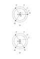
- FIG. 1 shows a case where the displacement sensors 100 are provided at three positions other than the positions facing each other
- FIG. 2B shows the positions facing each other and the positions facing each other. It shows the case where the displacement sensor 100 is provided at the positions other than the above and the three positions.
- a spacer is provided in the vicinity of the bearing of the bearing device 10 for the purpose of adjusting the preload or installing a lubrication mechanism.
- the bearings used in the general bearing device 10 are roughly classified into fixed side bearings and free side bearings, each of which is composed of a single row or a double row.
- the fixed side and the free side mean fixed and free in the axial direction.
- the bearing device 10 includes a housing 11, a rotating member 21, a front rolling bearing 31, a front outer ring side spacer 36, a front inner ring side spacer 38, a nut 39, and a rear rolling bearing 41. It has a rear outer ring side seat 46, a nut 47, a rear inner ring side seat 48, a drive motor 51, and a displacement sensor 100.
- a hollow rotating member 21 (spindle of a machine tool) is rotatably supported by a front rolling bearing 31 and a rear rolling bearing 41 with respect to a housing 11 which is a fixing member.
- the rotating member 21 is rotationally driven by a drive motor 51 arranged between the front rolling bearing 31 and the rear rolling bearing 41.
- the front side rolling bearing 31 as the front side bearing is provided between the housing 11 and the rotating member 21 in the vicinity of one end (front end) of the rotating member 21 in the axial direction, and is arranged so as to be a back surface combination. It is composed of an angular contact ball bearing 31a as a pair of first front side bearings having substantially the same dimensions and an angular contact ball bearing 31b as a second front side bearing.
- Each of the angular contact ball bearings 31a and 31b is between an outer ring 33 which is a stationary side raceway ring, an inner ring 34 which is a rotating side raceway ring, and an outer ring raceway groove which is a stationary side raceway and an inner ring raceway groove which is a rotating side raceway.
- each of the bearings 31a and 31b has an inner ring 34, an outer ring 33, and a ball 35 rotatably arranged between the inner ring 34 and the outer ring 33.
- Each of the angular contact ball bearings 31a and 31b has an outer ring 33 internally fitted to the housing 11 via an outer ring side spacer 36, and is fixed to the housing 11 by a front bearing outer ring retainer 37 bolted.
- each angular contact ball bearing 31a and 31b is externally fitted to the rotating member 21 via the inner ring side spacer 38, and is fixed to the rotating member 21 by a nut 39 fastened to the rotating member 21.
- the angular contact ball bearings 31a and 31b are loaded with a fixed position preload by the nut 39. Therefore, the position of the rotating member 21 in the rotation axis P direction is positioned by the front rolling bearing 31.
- the front outer ring side spacer 36 includes an intermediate spacer 36a arranged between the pair of angular contact ball bearings 31a and the angular contact ball bearings 31b, and a rear end spacer 36b behind the front rolling bearing 31.
- the front inner ring side spacer 38 is fitted to the rotating member 21 and is arranged between the front end spacer 38a in front of the front rolling bearing 31 and the pair of angular contact ball bearings 31a and the angular contact ball bearing 31b.
- the intermediate portion spacer 38b and the rear end spacer 38c behind the front rolling bearing 31 are provided.
- the radial outer surface (outer peripheral surface) 38d of the intermediate portion spacer 38b faces the displacement sensor 100.
- the radial outer surface 38d of the intermediate seat 38b is referred to as a facing surface.
- the facing surface 38d is a measuring surface for measuring the distance between the displacement sensor 100 and the intermediate seat 38b by the displacement sensor 100.
- the facing surface 38d is arranged behind the angular contact ball bearing 31a, which is the frontmost bearing.
- the position of the facing surface 38d changes due to the radial displacement of the rotating shaft P of the rotating member 21 or the change in the diameter of the rotating member 21.
- the rear rolling bearing 41 as a rear bearing is a cylindrical roller bearing, and is provided between the housing 11 and the rotating member 21 near the other end (rear end) of the rotating shaft P of the rotating member 21 in the axial direction. In addition, it has an outer ring 42, an inner ring 43, and a plurality of cylindrical rollers 44 as rolling elements.
- the outer ring 42 of the rear rolling bearing 41 is fitted in the housing 11 and is fixed in the housing 11 via the outer ring side spacer 46 by the rear bearing retainer 45 bolted to the housing 11.
- the inner ring 43 of the rear rolling bearing 41 is fixed to the rotating member 21 via the inner ring side spacer 48 by a nut 47 fastened to the rotating member 21.
- the rear outer ring side spacer 46 has a front end spacer 46a in front of the bearing 41 and a rear end spacer 46b behind the rear rolling bearing 41.
- the rear inner ring side spacer 48 is fitted to the rotating member 21.
- the rear inner ring side spacer 48 has a front end spacer 48a in front of the rear rolling bearing 41 and a rear end spacer 48b behind the rear rolling bearing 41.
- the drive motor 51 is composed of a stator 52 that is internally fitted in the housing 11 and a rotor 53 that is externally fitted in a rotating member 21 that faces the inner peripheral side of the stator 52 via a gap.
- the displacement sensor 100 is held in the housing 11 and positions positions facing each other on the circumference of a circle R (see FIG. 2A) defined on a plane orthogonal to the rotation axis P of the rotating member 21. It is provided at three or more positions except. That is, in this embodiment, three displacement sensors 100 are provided.
- FIG. 2A illustrates a case where the displacement sensor 100 is provided at three positions S1, S2, and S3 on the circumference of the circle R.
- the angle between the positions S1 and S2 is ⁇ 1
- the angle between the positions S2 and S3 is ⁇ 2
- the angle between the positions S3 and S1 is ⁇ 3.
- the positions S1, S2, and S3 are arranged so that they do not face each other on the circumference of the circle R, for example, each of ⁇ 1, ⁇ 2, and ⁇ 3 is 120 degrees. .. When ⁇ 1 is 180 degrees, S1 and S2 are in positions facing each other.
- the displacement sensor 100 is provided so as to face the facing surface 38d in a direction orthogonal to the rotation axis P of the rotating member 21.
- the displacement sensor 100 measures the distance from the facing surface 38d, and outputs an electric signal corresponding to the measured distance to the axial load measuring unit 101 of the control device 20.
- the displacement sensor 100 is installed on the non-rotating body side of the bearing device 10, and the measurement surface of the displacement sensor 100 faces the rotating body side of the bearing device 10.
- the displacement sensor 100 is a non-contact displacement sensor such as an eddy current displacement sensor, a capacitance displacement sensor, a laser displacement meter, or an air gap sensor.
- the connection between the bearing device 10 and the control device 20 may be a wired connection or a wireless connection.
- control device 20 includes an axial load measuring unit 101, a motor drive circuit 102, and a CPU 103.
- the shaft load measuring unit 101 operates under the control of the CPU 103.
- the shaft load measuring unit 101 receives the detected values of the three displacement sensors 100. More specifically, the axial load measuring unit 101 receives an electric signal corresponding to the distance to each of the three measuring surfaces input from the three displacement sensors 100, and rotates the rotating member 21 based on the electric signal.
- the displacement (misalignment) of the shaft P in the radial direction and the amount of change in the diameter of the rotating member 21 are measured.
- the shaft load measuring unit 101 calculates the shaft load based on the measurement results of the measured displacement (center deviation) of the rotating shaft P in the radial direction and the amount of change in the diameter of the rotating member 21, and outputs the calculation result of the shaft load to the CPU 103. Output.
- the displacement (misalignment) of the rotating shaft P in the radial direction is a deviation of the rotating member 21 from the reference position of the rotating shaft P in a direction orthogonal to the rotating shaft P.
- the change in the diameter of the rotating member 21 is a change in the diameter with respect to the reference diameter of the rotating member 21.
- the motor drive circuit 102 drives the drive motor 51 according to the control of the CPU 103.
- the CPU 103 controls the entire operation of the control device 20 by reading a control program stored in advance in a memory (not shown) and executing the read control program.
- the CPU 103 performs predetermined control based on the calculation result of the shaft load input from the shaft load measuring unit 101.
- the predetermined control is control for the motor drive circuit 102 for reducing the driving force of the drive motor 51, or indicates that it is abnormal when the load amount of the shaft load indicated by the measurement result is equal to or more than the threshold value. It is a control etc. to notify by.
- the control device 20 may have a display unit for displaying that the shaft load is abnormal. Alternatively, the control device 20 may output a signal to an external display device so that the display device displays information or an image regarding the axial load abnormality.
- the control device 20 is not limited to the case of calculating the load amount of the shaft load, but may be limited to calculating the displacement (center deviation) of the rotating shaft P in the radial direction and the amount of change in the diameter of the rotating member 21. ..
- the displacement (misalignment) of the rotating shaft P in the radial direction and the amount of change in the diameter of the rotating member 21 may be displayed on the display device to notify the display device.
- the control device 20 uses the circumscribed circle center method and the inscribed circle center with respect to the amount of radial displacement from the reference circle, with the rotating member 21 of the bearing device 10 rotated and an arbitrary state as a reference circle.
- a measurement circle is calculated from the measured values on the facing surfaces 38d at the three positions using an approximation method such as the method, the minimum region center method, or the minimum self-centered center method. At this time, it is preferable to perform a plurality of measurements in order to improve the measurement accuracy.
- the bearing device 10 is a machine that requires high-speed rotation and high rotation accuracy, its components are also manufactured with high accuracy. Further, the measured displacement amount is very small, about 1/1000 to 1/10000, with respect to the diameter of the measurement circle. From this, since sufficient measurement accuracy can be expected even with only one measurement, the difference between the reference circle and the measurement circle may be obtained instead of the above approximation method. Specifically, the output value of each displacement sensor 100 is used as a reference value or zero offset, and then the difference amount of the output value of each displacement sensor 100 from an arbitrary time point to another time point is measured.
- the average value of each difference amount on each facing surface 38d is the diameter of the facing surface 38d from the rotation axis P (diameter of the circle R shown in FIG. 2) and a predetermined reference circle. It is the amount of change between the diameter and the diameter.
- the displacement vector displacement amount of the rotation axis P is calculated from the difference (binary value) between each difference amount in the displacement sensor 100 at two positions among the displacement sensors 100 at three positions and the average value of each difference amount. calculate. At this time, since the displacement vector displacement amount of the rotation axis P can be calculated by the number of combinations of the displacement sensors 100 at the two positions, the displacement vector with high accuracy can be calculated by using the average value of these displacement vector displacement amounts.
- the amount of displacement can be obtained.
- the numerical value of the diameter of the circle R or the numerical value of the diameter of the rotating member 21 becomes unnecessary when calculating the displacement vector displacement amount and the diameter change amount. It can be calculated only by the measured values of the three displacement sensors 100. More specifically, the amount of change in diameter can be calculated from the measured values of the three displacement sensors 100, and the displacement vector displacement amount can be calculated using any two of the measured values of the three displacement sensors 100. At this time, since three values of the displacement vector displacement amount can be obtained by the combination, the accuracy of the displacement vector displacement amount is improved by averaging them.
- the displacement sensors 100 face each other (for example, in the case of FIG.
- the displacement vector displacement amount can be calculated by the above calculation method, but the displacement sensors 100 of the facing combination (for example, FIG. 2B). Since the displacement vector displacement amount cannot be calculated by the displacement sensors 100) at positions S1 and S2), the obtained displacement vector displacement amount becomes a binary value, and the accuracy is lowered.
- the change in the diameter of the rotating member 21 and the amount of displacement of the rotating shaft P in the radial direction measured by the spindle device 1 of the machine tool are the amount of centrifugal expansion with respect to the reference circle and the temperature difference between the installation position of the displacement sensor 100 and the measurement surface. It is caused by the difference in thermal expansion due to.
- the centrifugal expansion amount is constant at any position, but the difference in thermal expansion amount becomes smaller as the displacement sensor 100 is closer to the bearing because the deviation from the bearing becomes smaller.
- the difference in the amount of thermal expansion can be corrected if the relationship between the temperature rise of the bearing and the temperature rise at the position of the displacement sensor 100 is clarified in advance.
- the displacement sensor 100 is closest to the axial load.
- the amount of change and displacement at the same level as the bearing can be measured, and the distance between the tool end and the bearing (tool end (point of action), which greatly affects the rigidity of the bearing device 10, and the contact angle and rotation of the bearing with respect to the rotating member 21). It is possible to suppress an increase in the intersection point (support point) with the shaft P (distance), and it is possible to accurately measure the temperature change of the bearing due to rotation.
- the front rolling bearing 31 has two rolling bearings (angular contact ball bearings), but the front rolling bearing 31 may be composed of one or three or more rolling bearings.
- the configuration of the spindle device of the machine tool according to the present invention in the second embodiment is the same except that the bearing device 110 is provided instead of the bearing device 10 in FIG. 1, and thus the description thereof will be omitted.
- FIG. 3 the left direction will be described as the front direction and the right direction will be described as the rear direction.
- the description of the lower half of the bearing device 110 is omitted, and the description of the displacement sensor and the control device connected to the drive motor is omitted.
- parts having the same configuration as that of FIG. 1 are designated by the same reference numerals, and the description thereof will be omitted.
- the bearing device 110 includes a rotating member 21, a front rolling bearing 31, a front outer ring side spacer 36, a front inner ring side spacer 38, a nut 39, a rear rolling bearing 41, and a rear outer ring side spacer 46. It has a nut 47, a rear inner ring side bearing 48, a drive motor 51, a displacement sensor 100, and a housing 111.
- a hollow rotating member 21 (spindle shaft) is rotatably supported by a front rolling bearing 31 and a rear rolling bearing 41 with respect to the housing 111 which is a fixing member.
- the front inner ring side spacer 38 is fitted to the rotating member 21.
- the front inner ring side spacer 38 includes a front end spacer 38a in front of the front rolling bearing 31, an intermediate spacer 38b arranged between the pair of angular contact ball bearings 31a and the angular contact ball bearing 31b, and front rolling. It is provided with a rear end spacer 38c behind the bearing 31.
- the radial outer surface (outer peripheral surface) 38e of the rear end spacer 38c faces the displacement sensor 100.
- the radial outer surface 38e of the rear end spacer 38c is referred to as a facing surface.
- the facing surface 38e is a measuring surface for measuring the distance between the displacement sensor 100 and the rear end spacer 38c by the displacement sensor 100.
- the facing surface 38e is arranged behind the angular contact ball bearing 31a, which is the frontmost bearing.
- the position of the facing surface 38e changes due to the displacement (misalignment) of the rotating shaft P in the radial direction or the change in the diameter of the rotating member 21.
- the displacement sensor 100 is held in the housing 111, is located on the rear end side of the axial direction P with respect to the angular contact ball bearing 31b, and is located on the rear end spacer 38c of the front inner ring side spacer 38 closest to the drive motor 51. It is provided at three or more positions on the circumference of a circle defined on a plane orthogonal to the rotation axis P of the rotating member 21 to be located.
- the displacement sensor 100 is provided so as to face the facing surface 38e in a direction orthogonal to the rotation axis P of the rotating member 21.
- the displacement sensor 100 measures the distance from the facing surface 38e and outputs an electric signal corresponding to the measured distance to the axial load measuring unit 101 of the control device 20.
- the displacement sensor 100 is installed on the non-rotating body side of the bearing device 110, and the measurement surface of the displacement sensor 100 faces the rotating body side of the bearing device 110.
- control device according to the present embodiment has the same configuration as that in FIG. 1, the description thereof will be omitted. Further, since the operation of the bearing device 110 is the same as that of the bearing device 10 according to the first embodiment, the description thereof will be omitted.
- the front rolling bearing 31 and the rear rolling bearing 41 depending on the degree of heat generation of the front rolling bearing 31 itself or the rear rolling bearing 41 itself, or the degree of heat generation or heat dissipation from the drive motor 51, the front rolling bearing 31 and the rear rolling bearing 41
- the outer ring 33 and the outer ring 42 on the non-rotating body side of the bearing device 10 in the vicinity of the drive motor 51 are thermally the most severe.
- the facing surface 38e of the rear end spacer 38c of the front inner ring bearing 38 which is thermally harsh, is used as the measurement surface of the displacement sensor 100, so that not only the machining load but also the machining load is added.
- the configuration of the spindle device of the machine tool according to the present invention in the third embodiment is the same except that the bearing device 210 is provided instead of the bearing device 10 in FIG. 1, and thus the description thereof will be omitted.
- FIG. 4 the left direction will be described as the front direction and the right direction will be described as the rear direction.
- the description of the lower half of the bearing device 210 is omitted, and the description of the displacement sensor and the control device connected to the drive motor is omitted.
- parts having the same configuration as that of FIG. 1 are designated by the same reference numerals, and the description thereof will be omitted.
- the bearing device 210 includes a rotating member 21, a front rolling bearing 31, a front outer ring side spacer 36, a front inner ring side spacer 38, a nut 39, a rear rolling bearing 41, and a rear outer ring side spacer 46. It has a nut 47, a rear inner ring side bearing 48, a drive motor 51, a displacement sensor 100, and a housing 211.
- a hollow rotating member 21 (spindle shaft) is rotatably supported by a front rolling bearing 31 and a rear rolling bearing 41 with respect to the housing 211 which is a fixing member.
- the rear inner ring side spacer 48 is fitted to the rotating member 21.
- the radial outer surface (outer peripheral surface) 48c of the rear end spacer 48b of the rear inner ring side spacer 48 faces the displacement sensor 100.
- the radial outer surface 48c of the rear end spacer 48b is referred to as a facing surface.
- the facing surface 48c is a measuring surface for measuring the distance between the displacement sensor 100 and the rear end spacer 48b by the displacement sensor 100.
- the facing surface 48c is arranged behind the angular contact ball bearing 31a, which is the frontmost bearing. The position of the facing surface 48c changes due to the displacement (misalignment) of the rotating shaft P in the radial direction or the change in the diameter of the rotating member 21.
- the displacement sensor 100 is installed in the vicinity of the rear rolling bearing 41, which is a free bearing.
- the displacement sensor 100 is held in the housing 211, and is provided at three or more positions on the circumference of a circle defined on a plane orthogonal to the rotation axis P of the rotating member 21.
- the displacement sensor 100 is provided so as to face the facing surface 48c in a direction orthogonal to the rotation axis P of the rotating member 21.
- the displacement sensor 100 measures the distance from the facing surface 48c and outputs an electric signal corresponding to the measured distance to the axial load measuring unit 101 of the control device 20.
- the displacement sensor 100 is installed on the non-rotating body side of the bearing device 210, and the measurement surface of the displacement sensor 100 faces the rotating body side of the bearing device 210.
- control device according to the present embodiment has the same configuration as that in FIG. 1, the description thereof will be omitted. Further, since the operation of the bearing device 210 is the same as that of the bearing device 10 according to the first embodiment, the description thereof will be omitted.
- the displacement sensor 100 by arranging the displacement sensor 100 in the vicinity of the rear rolling bearing 41, the axial displacement vector of the rotating shaft P of the rotating member 21 and the change in the diameter of the rotating member 21 can be obtained. Can be measured.
- the configuration of the spindle device of the machine tool according to the present invention in the fourth embodiment is the same except that the bearing device 310 is provided instead of the bearing device 10 in FIG. 1, and thus the description thereof will be omitted.
- FIG. 5 the left direction will be described as the front direction and the right direction will be described as the rear direction.
- the description of the lower half of the bearing device 310 is omitted, and the description of the control device connected to the displacement sensor and the drive motor is omitted.
- the parts having the same configuration as that of FIG. 1 are designated by the same reference numerals, and the description thereof will be omitted.
- the bearing device 310 includes a rotating member 21, a front rolling bearing 31, a front outer ring side spacer 36, a front inner ring side spacer 38, a nut 39, a rear rolling bearing 41, and a rear outer ring side spacer 46. It has a nut 47, a rear inner ring side bearing 48, a drive motor 51, a displacement sensor 100, and a housing 311.
- a hollow rotating member 21 (spindle shaft) is rotatably supported by a front rolling bearing 31 and a rear rolling bearing 41 with respect to the housing 311 which is a fixing member.
- the rotating member 21 is rotationally driven by a drive motor 51 arranged between the front rolling bearing 31 and the rear rolling bearing 41.
- the rear inner ring side spacer 48 is fitted to the rotating member 21.
- the radial outer surface (outer peripheral surface) 48d of the front end spacer 48a of the rear inner ring side spacer 48 faces the displacement sensor 100.
- the radial outer surface 48d of the front end spacer 48a is referred to as a facing surface.
- the facing surface 48d is a measuring surface for measuring the distance between the displacement sensor 100 and the front end spacer 48a by the displacement sensor 100.
- the facing surface 48d is arranged behind the angular contact ball bearing 31a, which is the frontmost bearing. The position of the facing surface 48d changes due to the displacement (misalignment) of the rotating shaft P in the radial direction or the change in the diameter of the rotating member 21.
- the displacement sensor 100 is installed in the vicinity of the rear rolling bearing 41, which is a free bearing.
- the displacement sensor 100 is held in the housing 311 and is provided at three or more positions on the circumference of a circle defined on a plane orthogonal to the rotation axis P of the rotating member 21.
- the displacement sensor 100 is provided so as to face the facing surface 48d in a direction orthogonal to the rotation axis P of the rotating member 21.
- the displacement sensor 100 measures the distance from the facing surface 48d, and outputs an electric signal corresponding to the measured distance to the axial load measuring unit 101 of the control device 20.
- the displacement sensor 100 is installed on the non-rotating body side of the bearing device 310, and the measurement surface of the displacement sensor 100 faces the rotating body side of the bearing device 310.
- control device Since the control device according to the present embodiment has the same configuration as that in FIG. 1, the description thereof will be omitted. Further, since the operation of the bearing device 310 is the same as that of the bearing device 10 according to the first embodiment, the description thereof will be omitted.
- the amount of heat flowing from the drive motor 51 to the rear rolling bearing 41 can be easily estimated by setting the position closer to the drive motor 51 than the rear rolling bearing 41 as the measurement surface of the displacement sensor 100. ..
- the configuration of the spindle device of the machine tool according to the present invention in the fifth embodiment is the same except that the bearing device 410 is provided instead of the bearing device 10 in FIG. 1, and thus the description thereof will be omitted.
- FIG. 6 the left direction will be described as the front direction and the right direction will be described as the rear direction.
- a part of the bearing device 410 is shown, and the description of the displacement sensor and the control device connected to the drive motor is omitted.
- the parts having the same configuration as that of FIG. 1 are designated by the same reference numerals, and the description thereof will be omitted.
- the bearing device 410 includes a rotating member 21, a nut 39, a rear rolling bearing 41, a rear outer ring side spacer 46, a nut 47, a rear inner ring side spacer 48, a drive motor 51, and a displacement sensor. It has 100, a housing 411, a front rolling bearing 431, a front outer ring side spacer 436, and a front inner ring side spacer 438.
- the hollow rotating member 21 (spindle shaft) is rotatably supported by the front rolling bearing 431 and the rear rolling bearing 41 with respect to the housing 411 which is a fixing member.
- the rotating member 21 is rotationally driven by a drive motor 51 arranged between the front rolling bearing 431 and the rear rolling bearing 41.
- the front rolling bearing 431 is provided between the housing 411 and the rotating member 21, and is composed of a pair of angular contact ball bearings 431a and 431b arranged so as to be a back combination.
- Each of the angular contact ball bearings 431a and 431b is between an outer ring 433 which is a stationary side raceway ring, an inner ring 434 which is a rotating side raceway ring, and an outer ring raceway groove which is a stationary side raceway and an inner ring raceway groove which is a rotating side raceway.
- It is provided with a plurality of balls 435 as rolling elements arranged with a contact angle. That is, each bearing 431a and 431b has an inner ring 434, an outer ring 433, and a ball 435 rotatably arranged between the inner ring 434 and the outer ring 433.
- Each angular contact ball bearing 431a and 431b has an outer ring 433 fitted inside the housing 411 via an outer ring side spacer 436, and is fixed to the housing 411 by a front bearing outer ring retainer 37 bolted.
- each angular contact ball bearing 431a and 431b is fitted onto the rotating member 21 via the inner ring side spacer 438, and is fixed to the rotating member 21 by a nut 39 fastened to the rotating member 21. Therefore, the position of the rotating member 21 in the rotation axis P direction is positioned by the front rolling bearing 431.
- the inner ring 434 of the angular contact ball bearing 431a extends rearward from the outer ring 433 of the angular contact ball bearing 431a.
- the radial outer surface (outer peripheral surface) 434a of the inner ring 434 of the angular contact ball bearing 431a faces the displacement sensor 100.
- the radial outer surface 434a of the inner ring 434 of the angular contact ball bearing 431a is referred to as a facing surface.
- the facing surface 434a is a measuring surface for measuring the distance between the displacement sensor 100 and the inner ring 434 of the angular contact ball bearing 431a by the displacement sensor 100.
- the facing surface 434a is arranged behind the angular contact ball bearing 431a, which is the frontmost bearing.
- the position of the facing surface 434a changes due to the radial displacement (misalignment) of the rotating shaft P or the change in the diameter of the rotating member 21.
- the front outer ring side spacer 436 includes an intermediate spacer 436a arranged between the pair of angular contact ball bearings 431a and the angular contact ball bearings 431b, and a rear end spacer 436b behind the front rolling bearing 431.
- the front inner ring side spacer 438 is fitted to the rotating member 21.
- the front inner ring side spacer 438 includes a front end spacer 438a in front of the front rolling bearing 431, an intermediate spacer 438b arranged between the pair of angular contact ball bearings 431a and the angular contact ball bearing 431b, and a front rolling bearing 438b. It is provided with a rear end spacer 438c behind the bearing 431.
- the displacement sensor 100 is provided so as to face the facing surface 434a in a direction orthogonal to the rotation axis P of the rotating member 21.
- the displacement sensor 100 measures the distance from the facing surface 434a and outputs an electric signal corresponding to the measured distance to the axial load measuring unit 101 of the control device 20.
- the displacement sensor 100 is installed on the non-rotating body side of the bearing device 410, and the measurement surface of the displacement sensor 100 faces the rotating body side of the bearing device 410.
- control device Since the control device according to the present embodiment has the same configuration as that in FIG. 1, the description thereof will be omitted. Further, since the operation of the bearing device 410 is the same as that of the bearing device 10 according to the first embodiment, the description thereof will be omitted.
- the change in the diameter of the inner ring 434 of the front rolling bearing 431 can be measured more accurately.
- FIG. 6 the left direction will be described as the front direction and the right direction will be described as the rear direction.
- a part of the bearing device 410 is shown, and the description of the displacement sensor and the control device connected to the drive motor is omitted.
- the parts having the same configuration as that of FIG. 1 are designated by the same reference numerals, and the description thereof will be omitted.
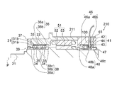
- the bearing device 510 includes a rotating member 21, a nut 39, a rear rolling bearing 41, a rear outer ring side spacer 46, a nut 47, a rear inner ring side spacer 48, a drive motor 51, and a displacement sensor. It has 500, a housing 511, a front rolling bearing 531, a front outer ring side spacer 536, and a front inner ring side spacer 538.
- the hollow rotating member 21 (spindle shaft) is rotatably supported by the front rolling bearing 531 and the rear rolling bearing 41 with respect to the housing 511 which is a fixing member.
- the rotating member 21 is rotationally driven by a drive motor 51 arranged between the front rolling bearing 531 and the rear rolling bearing 41.
- the front rolling bearing 531 is composed of a pair of angular contact ball bearings 531a and 531b provided between the housing 511 and the rotating member 21 and arranged so as to be a back combination.
- Each of the angular contact ball bearings 531a and 531b is between an outer ring 533 which is a stationary side raceway ring, an inner ring 534 which is a rotating side raceway ring, and an outer ring raceway groove which is a stationary side raceway and an inner ring raceway groove which is a rotating side raceway.
- It is provided with a plurality of balls 535 as rolling elements arranged with a contact angle. That is, each of the bearings 531a and 531b has an inner ring 534, an outer ring 533, and a ball 535 rotatably arranged between the inner ring 534 and the outer ring 533.
- Each of the angular contact ball bearings 531a and 531b has an outer ring 533 fitted inside the housing 511 via an outer ring side spacer 536, and is fixed to the housing 511 by a front bearing outer ring retainer 37 bolted to the housing 511.
- each angular contact ball bearing 531a and 531b is externally fitted to the rotating member 21 via the inner ring side spacer 538, and is fixed to the rotating member 21 by a nut 39 fastened to the rotating member 21. Therefore, the position of the rotating member 21 in the rotation axis P direction is positioned by the front rolling bearing 531.
- Each of the outer ring 533 and the inner ring 534 of the angular contact ball bearing 531a has a longer length in the rotation axis P direction than each of the outer ring 533 and the inner ring 534 of the angular contact ball bearing 531b.
- the outer ring 533 of the angular contact ball bearing 531a holds the displacement sensor 500.
- the radial outer surface (outer peripheral surface) 534a of the inner ring 534 faces the displacement sensor 500.
- the radial outer surface 534a of the inner ring 534 of the angular contact ball bearing 531a is referred to as a facing surface.
- the facing surface 534a is a measuring surface for measuring the distance between the displacement sensor 500 and the inner ring 534 of the angular contact ball bearing 531a by the displacement sensor 100.
- the facing surface 534a is arranged behind the angular contact ball bearing 531a, which is the frontmost bearing. The position of the facing surface 534a changes due to the radial displacement (misalignment) of the rotating shaft P or the change in the diameter of the rotating member 21.
- the front outer ring side spacer 536 is fitted to the rotating member 21.
- the front outer ring side spacer 536 includes an intermediate spacer 536a arranged between the pair of angular contact ball bearings 531a and the angular contact ball bearings 531b, and a rear end spacer 536b behind the front rolling bearing 531.
- the front inner ring side spacer 538 is fitted to the rotating member 21.
- the front inner ring side spacer 538 includes a front end spacer 538a in front of the front rolling bearing 531, an intermediate spacer 538b arranged between the pair of angular contact ball bearings 531a and the angular contact ball bearing 531b, and front rolling. It is provided with a rear end spacer 538c behind the bearing 531.
- the displacement sensors 500 are provided at three or more positions on the circumference of a circle defined on a plane orthogonal to the rotation axis P of the rotating member 21. That is, in this embodiment, three displacement sensors 500 are provided.
- the displacement sensor 500 is removably fitted with the first connector 500a held by the outer ring 533 of the angular contact ball bearing 531a and the first connector 500a, and is connected to the control device 20 through the housing 511. It has a second connector 500b and the like.
- the first connector 500a of the displacement sensor 500 is provided so as to face the facing surface 534a in the direction orthogonal to the rotation axis P of the rotating member 21.
- the displacement sensor 500 measures the distance from the facing surface 534a and outputs an electric signal corresponding to the measured distance to the axial load measuring unit 101 of the control device 20.
- the displacement sensor 500 is installed on the non-rotating body side of the bearing device 510, and the measurement surface of the displacement sensor 500 faces the rotating body side of the bearing device 510.
- the displacement sensor 500 is a non-contact displacement sensor such as an eddy current displacement sensor, a capacitance displacement sensor, a laser displacement meter, or an air gap sensor.
- control device Since the control device according to the present embodiment has the same configuration as that in FIG. 1, the description thereof will be omitted. Further, since the operation of the bearing device 510 is the same as that of the bearing device 10 according to the first embodiment, the description thereof will be omitted.
- the displacement sensor 500 is held by the outer ring 533 of the angular contact ball bearing 531a, and the displacement sensor 500 and the outer ring 533 are integrated to adjust the gap amount between the displacement sensor 500 and the facing surface 534a in advance. Can be kept.
- the housing when measuring the axial displacement vector of the rotating shaft P of the rotating member 21 and the change in the diameter of the rotating member 21. The influence of the displacement that occurs between the 511 and the outer ring 533 can be avoided.
- the displacement sensor 500 when the displacement sensor 500 and the control device 20 are connected by wire, the displacement sensor 500 is a connector type, and the first connector 500a is held by the outer ring 533 and assembled, and then the second one is assembled. Since the connector 500b can be connected, the displacement sensor 500 can be installed without disconnecting the signal line connecting the displacement sensor 500 and the control device 20.
- the facing surface 534a of the inner ring 534 as the measurement surface, it is possible to strictly measure the change in the diameter of the inner ring 534 of the front rolling bearing 531.
- the configuration of the spindle device of the machine tool according to the present invention in the seventh embodiment is the same except that the bearing device 610 is provided instead of the bearing device 10 in FIG. 1, and thus the description thereof will be omitted.
- FIG. 8 the left direction will be described as the front direction and the right direction will be described as the rear direction.
- a part of the bearing device 610 is shown, and the description of the control device connected to the displacement sensor and the drive motor is omitted.
- the parts having the same configuration as that of FIG. 1 are designated by the same reference numerals, and the description thereof will be omitted.
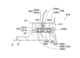
- the bearing device 610 includes a rotating member 21, a nut 39, a rear rolling bearing 41, a rear outer ring side spacer 46, a nut 47, a rear inner ring side spacer 48, a drive motor 51, and a displacement sensor. It has 600, a housing 611, a front rolling bearing 631, a front outer ring side spacer 636, and a front inner ring side spacer 638.
- a hollow rotating member 21 (spindle shaft) is rotatably supported by a front rolling bearing 631 and a rear rolling bearing 41 with respect to a housing 611 which is a fixing member.
- the rotating member 21 is rotationally driven by a drive motor 51 arranged between the front rolling bearing 631 and the rear rolling bearing 41.
- the front rolling bearing 631 is provided between the housing 611 and the rotating member 21, and is composed of a pair of angular contact ball bearings 631a and 631b arranged so as to be a back combination.
- Each of the angular contact ball bearings 631a and 631b is between an outer ring 633 which is a stationary side raceway ring, an inner ring 634 which is a rotating side raceway ring, and an outer ring raceway groove which is a stationary side raceway and an inner ring raceway groove which is a rotating side raceway.
- It is provided with a plurality of balls 635 as rolling elements arranged with a contact angle. That is, each of the bearings 631a and 631b has an inner ring 634, an outer ring 633, and a ball 635 rotatably arranged between the inner ring 634 and the outer ring 633.
- the outer ring 633 is internally fitted into the housing 611 via the outer ring side spacer 636, and the angular contact ball bearings 631a and 631b are fixed to the housing 611 by the front bearing outer ring retainer 37 bolted.
- each angular contact ball bearing 631a and 631b is externally fitted to the rotating member 21 via the inner ring side spacer 638, and is fixed to the rotating member 21 by a nut 39 fastened to the rotating member 21. Therefore, the position of the rotating member 21 in the rotation axis P direction is positioned by the front rolling bearing 631.
- the outer ring 633 of the angular contact ball bearing 631a extends rearward from the inner ring 634 of the angular contact ball bearing 631a and holds the displacement sensor 600.
- the front outer ring side spacer 636 includes an intermediate spacer 636a arranged between the pair of angular contact ball bearings 631a and the angular contact ball bearing 631b, and a rear end spacer 636b behind the front rolling bearing 631.
- the front inner ring side spacer 638 is fitted to the rotating member 21.
- the front inner ring side spacer 638 includes a front end spacer 638a in front of the front rolling bearing 631, an intermediate spacer 638b arranged between the pair of angular contact ball bearings 631a and the angular contact ball bearing 631b, and a front rolling bearing 631b. It is provided with a rear end spacer 638c behind the bearing 631.
- the radial outer surface (outer peripheral surface) 638d of the intermediate portion spacer 638b faces the displacement sensor 600. In the following description, the radial outer surface 638d of the intermediate portion spacer 638b is referred to as a facing surface.
- the facing surface 638d is a measuring surface for measuring the distance between the displacement sensor 600 and the intermediate seat 638b by the displacement sensor 600.
- the facing surface 638d is arranged behind the angular contact ball bearing 631a, which is the frontmost bearing. The position of the facing surface 638d changes due to the radial displacement (misalignment) of the rotating shaft P or the change in the diameter of the rotating member 21.
- the displacement sensors 600 are provided at three or more positions on the circumference of a circle defined on a plane orthogonal to the rotation axis P of the rotating member 21. That is, in this embodiment, three displacement sensors 600 are provided.
- the displacement sensor 600 is removably fitted with the first connector 600a held by the outer ring 633 of the angular contact ball bearing 631a and the first connector 600a, and is connected to the control device 20 through the housing 611. It has a second connector 600b and the like.
- the first connector 600a of the displacement sensor 600 is provided so as to face the facing surface 638d in the direction orthogonal to the rotation axis P of the rotating member 21.
- the displacement sensor 600 measures the distance from the facing surface 638d and outputs an electric signal corresponding to the measured distance to the axial load measuring unit 101 of the control device 20.
- the displacement sensor 600 is installed on the non-rotating body side of the bearing device 610, and the measurement surface of the displacement sensor 600 faces the rotating body side of the bearing device 610.
- the displacement sensor 600 is a non-contact displacement sensor such as an eddy current displacement sensor, a capacitance displacement sensor, a laser displacement meter, or an air gap sensor.
- control device Since the control device according to the present embodiment has the same configuration as that in FIG. 1, the description thereof will be omitted. Further, since the operation of the bearing device 610 is the same as that of the bearing device 10 according to the first embodiment, the description thereof will be omitted.
- the gap amount between the displacement sensor 600 and the facing surface 638d can be adjusted in advance by holding the displacement sensor 600 on the outer ring 633 of the angular contact ball bearing 631a.
- the housing when measuring the axial displacement vector of the rotating shaft P of the rotating member 21 and the change in the diameter of the rotating member 21. The influence of the displacement that occurs between the 611 and the outer ring 633 can be avoided.
- the configuration of the spindle device of the machine tool according to the present invention in the eighth embodiment is the same except that the bearing device 710 is provided instead of the bearing device 10 in FIG. 1, and thus the description thereof will be omitted.
- FIG. 9 the left direction will be described as the front direction and the right direction will be described as the rear direction.
- a part of the bearing device 710 is shown, and the description of the displacement sensor and the control device connected to the drive motor is omitted.
- the parts having the same configuration as that of FIG. 1 are designated by the same reference numerals, and the description thereof will be omitted.
- the bearing device 710 includes a rotating member 21, a front rolling bearing 31, a front outer ring side spacer 36, a nut 39, a rear rolling bearing 41, a rear outer ring side spacer 46, a nut 47, and a rear side. It has an inner ring side bearing 48, a drive motor 51, a displacement sensor 100, a housing 711, and a front inner ring side bearing 738.
- the bearing device 710 has a hollow rotating member 21 with respect to the housing 711, which is a fixing member. (Spindle shaft) is rotatably supported by a front rolling bearing 31 and a rear rolling bearing 41.
- the rotating member 21 is rotationally driven by a drive motor 51 arranged between the front rolling bearing 31 and the rear rolling bearing 41.
- the radial outer surface (outer peripheral surface) 21a of the rotating member 21 faces the displacement sensor 100.
- the radial outer surface 21a of the rotating member 21 is referred to as a facing surface.
- the facing surface 21a is a measuring surface for measuring the distance between the displacement sensor 100 and the rotating member 21 by the displacement sensor 100.
- the facing surface 21a is arranged behind the angular contact ball bearing 31a, which is the frontmost bearing. The position of the facing surface 21a changes due to the displacement (misalignment) of the rotating shaft P in the radial direction or the change in the diameter of the rotating member 21.
- the front inner ring side spacer 738 is fitted to the rotating member 21.
- the front inner ring side spacer 738 includes a front end spacer 738a in front of the front rolling bearing 31, and an intermediate spacer 738b arranged between the pair of angular contact ball bearings 31a and the angular contact ball bearings 31b. ing.
- the displacement sensor 100 is held in the housing 711 and is provided at three or more positions on the circumference of a circle defined on a plane orthogonal to the rotation axis P of the rotating member 21.
- the displacement sensor 100 is provided so as to face the facing surface 21a in a direction orthogonal to the rotation axis P of the rotating member 21.
- the displacement sensor 100 measures the distance from the facing surface 21a and outputs an electric signal corresponding to the measured distance to the axial load measuring unit 101 of the control device 20.
- the displacement sensor 100 is installed on the non-rotating body side of the bearing device 710, and the measurement surface of the displacement sensor 100 faces the rotating body side of the bearing device 710.
- control device Since the control device according to the present embodiment has the same configuration as that in FIG. 1, the description thereof will be omitted. Further, since the operation of the bearing device 610 is the same as that of the bearing device 10 according to the first embodiment, the description thereof will be omitted.
- the number of constituent elements can be reduced to make a simple configuration, and the spacer and the rotating member 21 are fitted to each other when the gap is fitted. It is possible to eliminate the influence of the error of the gap amount between the displacement sensor 100 and the measuring surface 21a due to the deviation between the rotating member and the rotating shaft P of the rotating member.
- the spindle device 200 of the machine tool has a pressure loss measuring unit 221, a compressed gas supply unit 230, a bearing device 240, an arithmetic processing unit PU, and a display unit DP.
- the spindle device 200 of the machine tool supplies the displacement detection unit 201 for detecting the radial displacement of the rotating member 21 using the compressed gas and the displacement detection unit 201 to supply the compressed gas to the front outer ring side.
- a pressure loss measuring unit 221 for measuring the pressure loss according to the gap between the spacer 36 and the front inner ring side spacer 38 is provided as a set.
- a plurality of sets (here, two sets) of the displacement detection unit 201 and the pressure loss measurement unit 221 are provided in the circumferential direction.
- the displacement measuring unit 200 includes an arithmetic processing unit PU that calculates the amount of load acting on the rotating member 21 based on the measurement results of each pressure loss measuring unit 221.
- the displacement detection unit 201 is provided in three or more directions on the circumference of the circle R defined on the plane orthogonal to the rotation axis P of the rotating member 21.
- the displacement detection unit 201 can be arranged at any position in the rotation axis P direction of the rotating member 21. More preferably, it is arranged near the rear of the front row bearing.
- Each of the displacement detection units 201 includes a front outer ring side spacer 36 and a front inner ring side spacer 38 of the front rolling bearing 31. That is, the front outer ring side spacer 36 has an outer peripheral side ring portion 36a that contacts the axial end faces of the outer ring 33 of the angular contact ball bearings 31a and 31b and the inner peripheral side ring portion that is narrower than the outer peripheral side ring portion 36a. It is equipped with 36b.
- the outer peripheral side ring portion 36a is formed with a recess 36c recessed from the outside to the inside in the central portion in the axial direction.
- the inner peripheral surface of the inner peripheral side ring portion 36b faces the outer peripheral surface of the front inner ring side spacer 38 so as to form a predetermined gap g to be measured.
- a funnel-shaped compressed gas discharge nozzle 202 extending radially from the bottom of the recess 36c of the outer peripheral side ring portion 36a to the inner peripheral surface is formed, and the compressed gas is discharged from the compressed gas discharge nozzle 202 to the front outer ring side spacer 36 and It is discharged into the measurement gap g between the front inner ring side spacers 38.
- the spindle shaft of a machine tool is a hollow shaft because a drawbar is provided in the inner diameter of the shaft as a mechanism for gripping a tool, and the spindle shaft is rotated at high speed in order to improve machining efficiency. It is assumed that. Therefore, particularly when high-speed rotation is used, the rotating members 21, the front inner ring side spacer 38, and the like expand by several to several tens of ⁇ m due to centrifugal force. Further, during the rotation of the spindle, a temperature difference occurs between the housing 241 and the rotating member 21, and in many cases, the rotating member 21 is higher. Therefore, the amount of gap between the housing 241 and the rotating member 21 is several to several tens of ⁇ m. It becomes smaller.
- a gap formed between the housing 241 and the rotating member 21, such as between the front outer ring side spacer 36 and the front inner ring side spacer 38, allows foreign matter to enter the inside of the spindle or the rolling bearing 31. In order to prevent this, it is set to a few mm at the maximum.
- the gap g to be measured between the front outer ring side spacer 36 and the front inner ring side spacer 38 is set to 0.05 mm to 0.5 mm when the rotating member 21 is stationary, but the radial displacement of the rotating member 21 is set. Since the amount of change in the pressure loss with respect to the relative value increases as the amount of the gap decreases, it is preferable to set the gap g to be measured to 0.05 mm to 0.2 mm.
- the front inner ring side spacer 38 provided in the displacement detection unit 201 is a rotating member 21 as much as possible. It is desirable to be coaxial with. Therefore, it is desirable that the front inner ring side spacer 38 is fitted to the shaft by an intermediate fit or a tighten fit.
- the housing 241 is formed with a circular opening 203 coaxially with the compressed gas discharge nozzle 202, reaching the recess 36c of the front outer ring side spacer 36 from the outer peripheral surface and reducing the inner diameter in two steps.
- one end of the compressed gas supply passage 204 formed on the rear side wall is opened in the opening 203.
- the other end of the compressed gas supply passage 204 communicates with the compressed gas supply passage 205 formed by opening to the rear end formed in the housing 241 and extending forward in the axial direction. ..
- the direction of the compressed gas supplied from the compressed gas supply passage 204 is changed from the axial direction to the radial direction in the opening 203, and the compressed gas is discharged.
- a gas connecting portion 206 as a gas direction changing portion supplied to the nozzle 202 is mounted.
- the gas connecting portion 206 has a shape that can be fitted into the opening 203, for example, an outer peripheral shape having the same shape as the inner peripheral shape of the opening 203, and internally communicates with the opening 203 into the gas passage 66a and the gas passage 66a.
- a gas passage 66b is formed in which one end communicates with the compressed gas discharge nozzle 202 and the other end communicates with the compressed gas discharge nozzle 202.
- An O-ring 67 is arranged between the side wall of the gas connection portion 206 and the inner wall of the opening 203, and an O-ring 68 is similarly arranged between the bottom surface of the gas connection portion 206 and the bottom surface of the recess 36c. O-rings 67 and 68 prevent the leakage of compressed air.
- the gas connecting portion 206 is positioned in the radial direction by the stepped portion of the outer peripheral surface coming into contact with the stepped portion of the inner peripheral surface of the opening 203. There is. Further, the gas connection portion 206 is prevented from coming out of the opening 203 by contacting the holding piece 209 whose end surface on the outer side in the radial direction is screwed to the outer peripheral surface of the housing 241.
- the gas connection portion 206 is not limited to the case where the holding piece 209 prevents the gas connection portion 206 from coming off, and a flange portion can be formed on the outer peripheral surface side of the gas connection portion 206 and the flange portion can be screwed to the gas connection portion 206.
- the fixing method of 206 to the housing 241 can be any fixing method.
- the pressure loss measuring unit 221 is compressed from the compressed gas supply unit 230 to a lubrication system by oil-air lubrication or oil mist lubrication (not shown) that supplies lubricating oil to the front rolling bearing 31 and the rear rolling bearing 41.
- Gas is supplied.
- the compressed gas supply unit 230 includes a compressor 231 that discharges compressed gas, a regulator 232 for a lubrication system that regulates the pressure of the compressed gas discharged from the compressor 231, and a regulator 233 for pressure loss measurement that is connected in parallel with the regulator 232. And have.
- the first embodiment is not limited to oil-air lubrication and oil mist lubrication. For example, it can also be applied to grease lubrication. Lubricants and greases are examples of lubricants.
- the lubrication system is a lubricant supply unit that supplies the lubricant to the bearings 31 and 41.
- the pressure loss measuring unit 221 includes a throttle 222 inserted in the compressed gas supply path and a differential pressure sensor 223 that detects the differential pressure on the upstream side and the downstream side of the throttle.
- the throttle 222 is inserted in a pipe 224 that connects the regulator 233 and the opening of the compressed gas supply passage 205 formed in the housing 241.
- the throttle amount of the throttle 222 is set so that the differential pressure detection value detected by the differential pressure sensor 223 when the radial displacement of the rotating member 21 is “0” during the rotation of the rotating member 21 becomes a preset value. Set to.
- the pressure on the downstream side of the throttle 222 represents the pressure loss corresponding only to the radial displacement of the rotating member 21 in consideration of the flow path resistance due to the pipe length and the pipe diameter from the throttle 222 to the displacement detection unit 201. Become.
- the low pressure side is connected to the pipe 224 on the downstream side of the throttle 222, and the high pressure side is connected to the regulator 233 via the pipe 225.
- the differential pressure between the compressed air pressure supplied from the regulator 233 and the downstream pressure of the throttle 222 connected to the displacement detection unit 201 that is, the pressure loss according to the displacement of the rotating member 21 in the displacement detection unit 201. Is detected, and the detected differential pressure detection value is output as an analog value or a digital value.
- the arithmetic processing unit PU is composed of an arithmetic processing device such as a microcomputer, for example, a differential pressure detection value output from the differential pressure sensor 223 of each pressure loss measurement unit 221 is input, and rotation is performed based on the differential pressure detection value.
- the converted displacement amount of the member 21 in the radial direction is calculated.
- the arithmetic processing unit PU multiplies the calculated displacement amount of the rotating member 21 in the radial direction by the axial rigidity value at the axial position of the compressed gas discharge nozzle 202 calculated in advance, so that the load applied to the rotating member 21 is applied.
- the amount is calculated, and the calculation result is output to the display DP and displayed.
- the shaft rigidity value is calculated based on the load point, the bearing position of the front rolling bearing 31, the bearing rigidity, the shaft rigidity, the axial position of the compressed gas discharge nozzle 202 of the displacement detection unit 201, and the like.
- the amount of load applied to the rotating member 21 is not limited to the case of calculating by the above-mentioned calculation.
- a known load is applied to the rotating member 21, and the differential pressure detection value output from the differential pressure sensor 223 of the pressure loss measuring unit 221 at that time is repeatedly measured to obtain the load and the differential pressure detection value.
- a load calculation map showing the relationship between the above is created, and this is stored in the storage unit of the arithmetic processing unit PU.
- the load amount can be calculated directly from the differential pressure detection value by referring to the load calculation map based on the differential pressure detection value detected by the differential pressure sensor 223 at the time of cutting.
- the load amount can be calculated by obtaining the equation of the characteristic line of the load calculation map and substituting the differential pressure detection value of the differential pressure sensor 223 into the obtained equation. ..
- each pressure loss measurement unit 221 is connected in parallel to the regulator 233 as shown in FIG. ..
- the bearing device 240 includes a rotating member 21, a front rolling bearing 31, a front outer ring side spacer 36, a front inner ring side spacer 38, a nut 39, a rear rolling bearing 41, and a rear outer ring side spacer 46. It has a nut 47, a rear inner ring side bearing 48, a drive motor 51, and a housing 241.
- the housing 241 is composed of a front cylindrical portion 242 and a rear cylindrical portion 243 that are divided into two parts between the front rolling bearing 31 and the drive motor 51.
- the front cylindrical portion 242 is composed of a small outer diameter portion 242a on the front side having a small outer diameter and a large outer diameter portion 242b on the rear side having a larger outer diameter than the small outer diameter portion 242a.
- the inner peripheral surfaces of the small outer diameter portion 242a and the large outer diameter portion 242b are formed to have the same inner diameter, but a bearing storage step for accommodating the front rolling bearing 31 from the front end side to the rear end side of the small outer diameter portion 242a.
- Part 242c is formed.
- the rear cylindrical portion 243 is formed by a large inner diameter portion 243a having a large inner diameter and a small inner diameter portion 243b having an inner diameter smaller than the large inner diameter portion 243a.
- the outer ring 33 is internally fitted into the bearing storage step portion 242c formed in the front cylindrical portion 242 of the housing 241 via the front outer ring side spacer 36, and is fitted into the front cylindrical portion 242 of the housing 241. It is fixed by a bolted front bearing outer ring retainer 37.
- the outer ring 42 of the rear rolling bearing 41 is fitted inside the small inner diameter portion 243b of the rear cylindrical portion 243 of the housing 241 and bolted to the small inner diameter portion 243b by the rear bearing retainer 45 to provide the rear outer ring side spacer 46. It is fixed to the small inner diameter portion 243b via.
- the drive motor 51 is a rotor fitted inside a stator 52 fitted into a large inner diameter portion 243a of a rear cylindrical portion 242 of a housing 241 and a rotor 21 fitted inside a rotating member 21 facing the inner peripheral side of the stator 52 via a gap. It is composed of 53.
- the compressed gas is supplied from the compressed gas supply unit 230 to the pressure loss measurement unit 221, and as described above, the radial displacement of the rotating member 21 is “0” in the state where the rotating member 21 of the bearing device 240 is rotated.
- the throttle amount of the throttle 222 of the pressure loss measuring unit 221 is adjusted so that the differential pressure detection value detected by the differential pressure sensor 223 becomes a preset set value.
- the compressed gas is regulated by the regulator 232, and the lubricating oil for the front rolling bearing 31 and the rear rolling bearing 41 (not shown) is adjusted.
- Compressed gas at a set pressure is supplied to the supply system, and the supply of the lubricant to the front rolling bearing 31 and the rear rolling bearing 41 is started.
- the compressed gas discharged from the compressor 231 is adjusted by the regulator 233 and supplied to the pressure loss measuring unit 221.
- the compressed gas supplied to the pressure loss measuring unit 221 is input to the compressed gas supply passage 205 of the housing 241 via the throttle 222.
- the compressed gas input to the compressed gas supply passage 205 is turned 90 degrees from the axial direction to the radial direction at the gas connection portion 206 from the compressed gas supply passage 204 and is supplied to the compressed gas discharge nozzle 202.
- the compressed gas supplied to the compressed gas discharge nozzle 202 is supplied to the measured gap g between the front outer ring side spacer 36 and the front inner ring side spacer 38, and the distance between the measured gaps g, that is, the radial displacement of the rotating member 21.
- the interval of the gap g to be measured becomes smaller, and the pressure loss becomes smaller accordingly, and conversely, when the displacement in the radial direction becomes smaller, the interval of the gap g to be measured becomes larger. Therefore, the pressure loss becomes large.
- the gap g to be measured as described above, when the rotating member 21 of the hollow shaft rotates at high speed, the rotating member 21 and the front inner ring side spacer 38 expand due to centrifugal force, and the housing 241 On the other hand, the gap becomes smaller due to the high temperature of the rotating member 21.
- the differential pressure detection value detected by the differential pressure sensor 223 becomes a preset value, and the radial displacement of the rotating member 21 is “0”.
- the differential pressure detection value input from the differential pressure sensor 223 is converted into the radial displacement of the rotating member 21, and the converted radial displacement is multiplied by the preset axial rigidity value.
- the amount of load applied to the rotating member 21 is calculated.
- the calculated load amount is output to the display DP and displayed. In this case, since the displacement in the radial direction is "0", the load amount displayed on the display DP is "0".
- a pressure loss is generated in the compressed gas discharged from the compressed gas discharge nozzles 202 of the plurality of displacement detection units 201 according to the radial direction displacement of the rotating member 21.
- This pressure loss is detected as a differential pressure detection value by the differential pressure sensor 223 of the pressure loss measuring unit 221.
- the arithmetic processing unit PU By supplying the detected differential pressure detection value to the arithmetic processing unit PU, the arithmetic processing unit PU converts the differential pressure detection value into the radial displacement of the rotating member 21 as described above, and converts it into the converted radial displacement.
- the amount of load applied to the rotating member 21 is calculated by multiplying the shaft rigidity value set in advance. The calculated load amount is output to the display DP and displayed.
- the compressed gas is discharged by supplying the compressed gas to the displacement detection unit 201 including the front outer ring side spacer 36 and the front inner ring side spacer 38 of the front rolling bearing 31.
- the compressed gas is discharged from the nozzle 202 into the gap g to be measured between the front outer ring side spacer 36 and the front inner ring side spacer 38. Therefore, a pressure loss of the compressed gas occurs according to the interval of the gap g to be measured, that is, the radial displacement of the rotating member 21.
- the pressure loss is detected by the differential pressure sensor 223 of the pressure loss measuring unit 221 provided on the outside of the housing 241 and the detected differential pressure detection value is supplied to the arithmetic processing unit PU to load the rotating member 21. Can be calculated.
- the displacement detection unit 201 is provided with a front outer ring side spacer 36 and a front inner ring side spacer 38 facing each other through a predetermined gap g to be measured, a compressed gas supply passage 204, a gas connection portion 206, and a compressed gas discharge nozzle 202. It is possible to generate a pressure loss according to the radial displacement of the rotating member 21 with a simple configuration. Therefore, since the displacement detection unit 201 does not require an electrically operating component, it is not necessary to consider wiring routing and electrical insulation.
- the pressure loss measuring unit 221 supplies the compressed gas to the displacement detecting unit 201 via the throttle 222, and supplies the compressed gas to the pressure and pressure loss measuring unit 221 on the downstream side of the throttle 222, that is, the displacement detecting unit 201 side.
- the pressure loss in the displacement detection unit 201 can be measured by detecting the differential pressure from the original pressure of. Then, the detected differential pressure detection value is converted into the radial displacement of the rotating member 21 and then the load amount applied to the rotating member 21 is calculated, or the load amount directly applied to the rotating member 21 from the differential pressure is calculated. It can be calculated.
- the radial displacement of the rotating member 21 can be calculated by using the compressed gas with a simple configuration, or the load amount applied to the rotating member 21. Can be calculated.
- the present invention is not limited to this, and the gas passage 66b of the gas connection portion 206 is provided.
- the pressure loss measuring unit 221 may be connected to the opening by extending to the outer peripheral side.
- the compressed gas supply passage 205 may be omitted, the compressed gas supply passage 204 may be opened on the outer peripheral surface of the housing 241 and the pressure loss measuring unit 221 may be connected to the opening.
- the throttle amount of the throttle 222 of the pressure loss measuring unit 221 is set in a state where the rotating member 21 of the bearing device 240 is rotated and the radial displacement of the rotating member 21 is “0”.
- the case where the differential pressure detection value detected by the differential pressure sensor 223 is adjusted so as to be a preset set value has been described.
- the present invention is not limited to this adjustment.
- the differential pressure of each pressure loss measuring unit 221 is adjusted to a certain value by the throttle 222 of the pressure loss measuring unit 221 in a state where the rotating member 21 of the bearing device 240 is stopped (state of 0 rotation) without an external load. , This state is set as displacement 0.
- the CPU 103 of the control device 20 performs predetermined control based on the calculation result of the axial load, but the present invention is not limited to this, and the function of the control device 20 is not limited to this.
- the shaft load may be calculated by a single electronic component provided with the above, and a predetermined control may be performed based on the calculation result.
- any two or more of the configurations in the first to fourth embodiments may be combined, or any two of the configurations in the fifth to eighth embodiments may be combined.
- the above configurations may be combined, or the above-mentioned fifth to eighth embodiments may be compared with the configuration in which any two or more of the above-mentioned first to fourth embodiments are combined. Any one or more of the configurations in the above may be combined.
Landscapes
- Engineering & Computer Science (AREA)
- General Engineering & Computer Science (AREA)
- Physics & Mathematics (AREA)
- General Physics & Mathematics (AREA)
- Mechanical Engineering (AREA)
- Rolling Contact Bearings (AREA)
- Length Measuring Devices With Unspecified Measuring Means (AREA)
- Machine Tool Sensing Apparatuses (AREA)
- Turning (AREA)
Abstract
回転部材と、回転部材を回転可能に支持する軸受と、軸受を保持するハウジングと、ハウジングまたは軸受の非回転部分に設けられて、回転部材と共に回転する面までの距離を測定するセンサと、を有する軸受装置に用いられる算出方法であって、回転部材の回転軸と直交する面上に、3つ以上の位置に設けられるセンサによる測定結果に基づいて、回転部材の径の変化量を算出する。
Description
本発明は、算出方法、軸受装置及び工作機械の主軸装置に関する。
近年、工作機械の主軸(スピンドル)において、切削荷重をコントロールし、加工の高速化、高精度化および軸受の長寿命化に繋げようとする動きが強まっており、その方策の一つとして、運転中の軸荷重量を測定することに対するニーズが高まっている。また、使用中の軸受の異常を事前に検知する技術へのニーズも同様に高まっており、軸受の長寿命化と合わせて、加工ラインそのものを可能な限り止めずに運用しようとする動きが強まっている。
また、加工中の軸荷重量を直接測定することは非常に困難であるため、その代替手段として、渦電流変位センサ等の非接触変位センサを用いて軸変位を計測し、軸変位を切削荷重へ換算する手法が採られている。軸変位から切削荷重へ換算するためには、工作機械スピンドルの剛性値が必要となるが、その剛性値には、使用される軸受の剛性が大きく影響する。
軸受は、構造的に、回転による遠心変形、摩擦およびモータなどの発熱による熱変形、具体的には、軸受の内輪と外輪との温度差による熱膨張差の影響により、その剛性が大きく変化する特性を有している。そのため、軸変位から切削荷重へ換算するためには、軸変位だけでなく、軸受の剛性変化による工作機械スピンドルの剛性変化も考慮しなければならない。
一方、軸受の熱膨張差の変化量は、軸受の異常の検知にも活用できる。軸受の劣化に伴って転がり摩擦が増大し、軸受の発熱が増大するが、そのとき同時に熱膨張差も変化するため、その変化を監視することで軸受の状態が推測でき、主軸の故障などの重大な問題の未然防止や、前記監視結果をもとに軸受の状態を維持するように運転条件を調整することで、軸受を延命させることが可能となる。
また、従来、軸変位をベクトルで測定する方法としては、直交する2点で測定する方法が一般的であるが、この方法では測定対象の径が一定であることを前提としており、軸変位と同時に径の変化が発生する場合に対応ができなくなる。
このような状況において、特許文献1は、回転体の芯ずれ算出方法に関し、回転体を回転させながら周方向の外表面に沿った3点の測定データから計算円を算出し、算出した計算円に基づいて回転体の芯ずれを算出することを開示している。特許文献1の方法によれば、測定点を3点とすることにより、測定平面上において1つの円を定めることができるため、軸変位ベクトルと径の変化量とを算出することが可能となる。
本発明は、回転部材の回転軸と直交する面上における3つ以上の位置の測定データを用いて、回転軸のラジアル方向の変位量と回転部材の径の変化量とを測定することができる算出方法、軸受装置及び工作機械の主軸装置を提供することを目的としている。
上記目的を達成するために、本発明の一態様に係る算出方法は、回転部材と、前記回転部材を回転可能に支持する軸受と、前記軸受を保持するハウジングと、前記ハウジングまたは前記軸受の非回転部分に設けられて、前記回転部材と共に回転する面までの距離を測定するセンサと、を有する軸受装置に用いられる算出方法であって、前記回転部材の回転軸と直交する面上に、3つ以上の位置に設けられる前記センサによる測定結果に基づいて、前記回転部材の径の変化量を算出する。
また、本発明の一態様に係る算出方法は、軸受を介して回転部材を回転可能にハウジングに支持する軸受装置において前記軸受の周囲の少なくとも3方向から前記回転部材と前記ハウジングの間の被測定隙間に圧縮気体を供給するステップと、前記圧縮気体の圧力変化を検出するステップと、前記検出された圧力変化に基づいて前記回転部材の径の変化量を算出するステップと、を有する。
また、本発明の一態様に係る軸受装置は、回転部材と、前記回転部材を回転可能に支持する軸受と、前記軸受を保持するハウジングと、前記ハウジングまたは前記軸受の非回転部分に設けられて、前記回転部材と共に回転する面までの距離を測定するセンサと、を備え、前記センサは、前記回転部材の回転軸と直交する面上に定義される円の円周上において、3つ以上の位置に設けられる。
また、本発明の一態様に係る工作機械の主軸装置は、回転部材と、前記回転部材を回転可能に支持する軸受と、前記軸受を保持するハウジングと、前記ハウジングまたは前記軸受の非回転部分に設けられて、前記回転部材と共に回転する面までの距離を測定するセンサと、を有する工作機械の軸受装置であって、前記センサは、前記回転部材の回転軸と直交する面上に、3つ以上の位置に設けられ、前記軸受装置は、前記センサによる測定結果に基づいて、前記回転部材の径の変化量を算出する算出部をさらに有する。
また、本発明の一態様に係る工作機械の主軸装置は、軸受を介して回転部材を回転可能にハウジングに支持する工作機械の軸受装置であって、前記軸受の周囲の少なくとも3方向から前記回転部材と前記ハウジングの間の被測定隙間に圧縮気体を供給する圧縮気体供給部と、前記圧縮気体の圧力変化を検出する検出部と、前記検出された圧力変化に基づいて前記回転部材の径の変化量を算出する算出部と、を有する。
本発明に係る算出方法の一態様によれば、回転部材の回転軸と直交する面上における3つ以上の位置の測定データを用いて、回転軸のラジアル方向の変位量と回転部材の径の変化量とを測定することができる。
また、本発明に係る軸受装置では、回転部材の回転軸と直交する面上における3つ以上の位置の測定データを用いて、回転軸のラジアル方向の変位量と回転部材の径の変化量とを測定することができる。
また、本発明に係る工作機械の主軸装置では、回転部材の回転軸と直交する面上における3つ以上の位置の測定データを用いて、回転軸のラジアル方向の変位量と回転部材の径の変化量とを測定することができる。
以下に、添付図面を参照して、本発明の実施形態を説明する。図中、同一又は類似の部分には同一又は類似の符号を付している。ただし、図面は模式的なものであり、厚みと平面寸法との関係、各層の厚みの比率等は現実のものとは異なることに留意すべきである。したがって、具体的な厚みや寸法は以下の説明を参酌して判断すべきものである。又、図面相互間においても互いの寸法の関係や比率が異なる部分が含まれていることはもちろんである。
また、以下に示す実施形態は、本発明の技術的思想を具体化するための装置や方法を例示するものであって、本発明の技術的思想は、構成部品の材質、形状、構造、配置等を下記のものに特定するものでない。本発明の技術的思想は、特許請求の範囲に記載された請求項が規定する技術的範囲内において、種々の変更を加えることができる。
(第1実施形態)
<工作機械の主軸装置の構成>
まず、本発明に係る工作機械の主軸装置の第1実施形態における構成について、図1を参照して説明する。
<工作機械の主軸装置の構成>
まず、本発明に係る工作機械の主軸装置の第1実施形態における構成について、図1を参照して説明する。
工作機械の主軸装置1は、軸受装置10と、制御装置20と、を有している。
軸受装置10は、モータビルトイン方式であり、転がり軸受で支持する回転部材の回転軸のラジアル方向の変位量と回転部材の径の変化量とを検出して軸荷重を測定可能になっている。なお、軸受装置10の構成の詳細については後述する。
制御装置20は、軸受装置10が測定した測定結果に基づいて、軸荷重量を算出する。制御装置20は、軸荷重測定部101と、モータ駆動回路102と、CPU103と、を有する。
<軸受装置の構成>
次に、軸受装置10の構成について、図1及び図2を参照して説明する。図1において、左方向を前方向及び右方向を後方向として説明する。図2において、図2(a)は、互いに対向する位置を除く3つの位置に変位センサ100を設けた場合を示しており、図2(b)は、互いに対向する位置と、互いに対向する位置以外の位置と、の3つの位置に変位センサ100を設けた場合を示している。
次に、軸受装置10の構成について、図1及び図2を参照して説明する。図1において、左方向を前方向及び右方向を後方向として説明する。図2において、図2(a)は、互いに対向する位置を除く3つの位置に変位センサ100を設けた場合を示しており、図2(b)は、互いに対向する位置と、互いに対向する位置以外の位置と、の3つの位置に変位センサ100を設けた場合を示している。
一般的に、軸受装置10の軸受の近傍には、予圧の調整又は潤滑機構の設置等を理由として間座が設けられている。また、一般的な軸受装置10に使用される軸受は、固定側軸受と自由側軸受とに大別され、それぞれ単列または複列で構成される。ここで、固定側および自由側は、軸方向において固定および自由という意味である。
具体的には、軸受装置10は、ハウジング11と、回転部材21と、前側転がり軸受31と、前側外輪側間座36と、前側内輪側間座38と、ナット39と、後側転がり軸受41と、後側外輪側間座46と、ナット47と、後側内輪側間座48と、駆動モータ51と、変位センサ100と、を有している。
軸受装置10は、固定部材であるハウジング11に対して、中空状の回転部材21(工作機械のスピンドル)が前側転がり軸受31及び後側転がり軸受41によって回転自在に支持されている。回転部材21は、前側転がり軸受31と後側転がり軸受41との間に配置された駆動モータ51によって回転駆動される。
前側軸受としての前側転がり軸受31は、ハウジング11と回転部材21との間において、回転部材21の回転軸Pの軸方向の一端(前端)近傍に設けられており、背面組合せとなるように配置された略同一寸法の一対の第1の前側軸受としてのアンギュラ玉軸受31a及び第2の前側軸受としてのアンギュラ玉軸受31bで構成されている。アンギュラ玉軸受31a及び31bの各々は、静止側軌道輪である外輪33と、回転側軌道輪である内輪34と、静止側軌道である外輪軌道溝と回転側軌道である内輪軌道溝との間に、接触角を持って配置された転動体としての複数の玉35と、を備えている。つまり、各軸受31a、31bは、内輪34と、外輪33と、内輪34と外輪33との間に回転可能に配置された玉35を有している。
各アンギュラ玉軸受31a及び31bは、ハウジング11に外輪側間座36を介して外輪33が内嵌され、ハウジング11にボルト締めされた前側軸受外輪押え37によって固定されている。
また、各アンギュラ玉軸受31a及び31bの内輪34は、回転部材21に内輪側間座38を介して外嵌され、回転部材21に締結されたナット39によって回転部材21に固定されている。アンギュラ玉軸受31a及び31bは、ナット39によって定位置予圧が負荷されている。したがって、前側転がり軸受31によって回転部材21の回転軸P方向の位置が位置決めされている。
前側外輪側間座36は、一対のアンギュラ玉軸受31aとアンギュラ玉軸受31bとの間に配置される中間部間座36aと、前側転がり軸受31よりも後方の後端部間座36bと、を有している。
前側内輪側間座38は、回転部材21に嵌合しており、前側転がり軸受31よりも前方の前端部間座38aと、一対のアンギュラ玉軸受31aとアンギュラ玉軸受31bとの間に配置される中間部間座38bと、前側転がり軸受31よりも後方の後端部間座38cと、を備えている。中間部間座38bの径方向外面(外周面)38dが変位センサ100と対向している。以下の記載において、中間部間座38bの径方向外面38dを対向面と称する。対向面38dは、変位センサ100によって変位センサ100と中間部間座38bとの間の距離を測定するための測定面である。対向面38dは、最も前方の軸受であるアンギュラ玉軸受31aよりも後方に配置されている。対向面38dの位置は、回転部材21の回転軸Pのラジアル方向の変位又は回転部材21の径の変化により変化する。
後側軸受としての後側転がり軸受41は、円筒ころ軸受であり、ハウジング11と回転部材21との間において、回転部材21の回転軸Pの軸方向の他端(後端)近傍に設けられていると共に、外輪42と、内輪43と、転動体としての複数の円筒ころ44と、を有する。後側転がり軸受41の外輪42は、ハウジング11に内嵌され、ハウジング11にボルト締結された後側軸受押え45によって外輪側間座46を介してハウジング11内に固定されている。後側転がり軸受41の内輪43は、回転部材21に締結されたナット47によって内輪側間座48を介して回転部材21に固定されている。
後側外輪側間座46は、軸受41よりも前方の前端部間座46aと、後側転がり軸受41よりも後方の後端部間座46bと、を有している。
後側内輪側間座48は、回転部材21に嵌合している。後側内輪側間座48は、後側転がり軸受41よりも前方の前端部間座48aと、後側転がり軸受41よりも後方の後端部間座48bと、を有している。
駆動モータ51は、ハウジング11に内嵌されさたステータ52と、ステータ52の内周側に間隙を介して対向する回転部材21に外嵌されたロータ53とで構成されている。
変位センサ100は、ハウジング11に保持されており、回転部材21の回転軸Pと直交する面上に定義される円R(図2(a)参照)の円周上において、互いに対向する位置を除く3つ以上の位置に設けられる。つまり、本実施形態では、変位センサ100が3つ設けられる。図2(a)は、変位センサ100が円Rの円周上の3つの位置S1、S2及びS3に設けられる場合を例示している。図2(a)において、位置S1とS2との間の角度をθ1、位置S2とS3との間の角度をθ2、及び位置S3とS1との間の角度をθ3とする。図2(a)に示すように、位置S1、S2及びS3は、円Rの円周上において互いに対向しないように、例えばθ1、θ2及びθ3の各々が120度となるように配置されている。θ1が180度である場合には、S1とS2とが互いに対向する位置になる。
変位センサ100は、回転部材21の回転軸Pと直交する方向において、対向面38dに対向して設けられている。変位センサ100は、対向面38dとの距離を測定し、測定した距離に応じた電気信号を制御装置20の軸荷重測定部101に出力する。変位センサ100は、軸受装置10の非回転体側に設置されており、変位センサ100の測定面は、軸受装置10の回転体側と対向している。
変位センサ100は、渦電流変位センサ、静電容量変位センサ、レーザ変位計またはエアギャップセンサ等の非接触変位センサである。
<制御装置の構成>
次に、軸受装置10に接続されている制御装置20の構成について、図1を参照して説明する。軸受装置10と制御装置20との接続は、有線接続でもよいし、無線接続でもよい。
次に、軸受装置10に接続されている制御装置20の構成について、図1を参照して説明する。軸受装置10と制御装置20との接続は、有線接続でもよいし、無線接続でもよい。
上記したように、制御装置20は、軸荷重測定部101と、モータ駆動回路102と、CPU103と、を備えている。
軸荷重測定部101は、CPU103の制御によって動作する。軸荷重測定部101は、3つの変位センサ100の検出値を受信する。より詳しくは、軸荷重測定部101は、3つの変位センサ100から入力される3つの測定面の各々との距離に応じた電気信号を受信し、当該電気信号に基づいて、回転部材21の回転軸Pのラジアル方向の変位(芯ずれ)および回転部材21の径の変化量を測定する。軸荷重測定部101は、測定した回転軸Pのラジアル方向の変位(芯ずれ)および回転部材21の径の変化量の測定結果に基づいて軸荷重を算出し、軸荷重の算出結果をCPU103に出力する。ここで、回転軸Pのラジアル方向の変位(芯ずれ)とは、回転部材21の回転軸Pの基準位置からの回転軸Pと直交する方向におけるずれである。また、回転部材21の径の変化とは、回転部材21の基準となる径に対する径の変化である。
モータ駆動回路102は、CPU103の制御に従って、駆動モータ51を駆動させる。
CPU103は、図示しないメモリに予め記憶されている制御プログラムを読み出して、読み出した制御プログラムを実行することにより制御装置20の全体の動作を制御する。CPU103は、軸荷重測定部101から入力される軸荷重の算出結果に基づいて、所定の制御を行う。ここで、所定の制御は、駆動モータ51の駆動力を低下させるためのモータ駆動回路102に対する制御、又は測定結果の示す軸荷重の荷重量が閾値以上である場合に異常であることを表示等して報知する制御等である。軸荷重が異常であることを表示する表示部は、制御装置20が有していてもよい。あるいは、制御装置20は、外部の表示装置に信号を出力して、当該表示装置が軸荷重異常に関する情報や画像を表示してもよい。
なお、制御装置20は、軸荷重の荷重量を算出する場合に限らず、回転軸Pのラジアル方向の変位(芯ずれ)および回転部材21の径の変化量を算出することにとどめてもよい。この場合には、例えば回転軸Pのラジアル方向の変位(芯ずれ)および回転部材21の径の変化量を表示装置に表示して報知するようにしてもよい。
<工作機械の主軸装置の動作>
次に、工作機械の主軸装置1の動作について、説明する。
次に、工作機械の主軸装置1の動作について、説明する。
制御装置20は、軸受装置10の回転部材21を回転させた状態で、任意の状態を基準円として、基準円からの径方向への変位量に対して、外接円中心法、内接円中心法、最小領域中心法又は最小自乗中心法等の近似法を用いて、3つの位置の対向面38dにおける測定値から測定円を算出する。この際に、測定精度を高めるために複数回の測定を行うことが好ましい。
また、軸受装置10は、高速回転かつ高い回転精度を要求される機械であることから、その構成要素も高い精度で製作される。また、測定変位量は、測定円の径に対し、1/1000乃至1/10000程度と非常に小さい。これより、1回の測定のみでも十分な測定精度が見込めるため、上記の近似法ではなくて、基準円と測定円との差分を求めてもよい。具体的には、各変位センサ100の出力値を基準値とするかゼロオフセットし、その後に任意の時点から別の時点までの各変位センサ100の出力値の差分量を計測する。そして、各変位センサ100の測定面である各対向面38dにおける各差分量の平均値が対向面38dの回転軸Pからの径(図2に示す円Rの径)と、所定の基準円の径と、の径の変化量となる。また、3つの位置の変位センサ100のうちの2つの位置の変位センサ100における各差分量と、この各差分量の平均値と、の差(2値)より回転軸Pの変位ベクトル変位量を算出する。この際に、2つの位置の変位センサ100の組み合わせの数だけ回転軸Pの変位ベクトル変位量を算出可能であるため、これらの変位ベクトル変位量の平均値を使用することにより高い精度の変位ベクトル変位量を得ることができる。なお、回転軸Pに対する円Rの円周上において隣り合う変位センサ100間の各角度(図2の場合にはθ1、θ2及びθ3)が同一角度に近いほど、上記の変位量の測定精度を高くすることができる。
変位センサ100を図2(a)に示す配置とすることで、変位ベクトル変位量および径の変化量を算出する際に、円Rの径の数値または回転部材21の径の数値が不要となり、3つの変位センサ100の測定値のみで算出可能となる。より具体的には、3つの変位センサ100の測定値から径の変化量が算出できると共に、3つの変位センサ100の測定値のうち、任意の2つを用いて変位ベクトル変位量が算出できる。このとき変位ベクトル変位量は組合せにより3値得られるため、それらを平均化することで変位ベクトル変位量の精度が高まる。尚、変位センサ100が対向する場合(例えば図2(b)の場合)も上記の算出方法にて変位ベクトル変位量は算出可能であるが、対向する組合せの変位センサ100(例えば図2(b)の位置S1及びS2の変位センサ100)では変位ベクトル変位量が算出不可となるため、得られる変位ベクトル変位量が2値となり、精度が低下することになる。
また、図2(a)及び図2(b)のいずれの場合においても、円Rの径の値または回転部材21の径の値が明らかである場合には、3つの変位センサ100の測定値と合わせて、各変位センサ100の配置軸上における回転部材21の径の座標が定まるため、それらの座標の変化から変位ベクトル変位量および径の変化量が算出可能となる。
工作機械の主軸装置1により計測される回転部材21の径の変化及び回転軸Pのラジアル方向の変位量は、基準円に対する遠心膨張量と、変位センサ100の設置位置と測定面との温度差による熱膨張差と、により生じる。ここで、遠心膨張量は、何れの位置でも一定となるが、熱膨張量差は、変位センサ100が軸受に近いほど、軸受との乖離が小さくなるため小さくなる。ただし、熱膨張量差は、軸受の温度上昇と、変位センサ100の位置における温度上昇と、の関係が予め明らかになっていれば補正可能である。
このように、本実施形態によれば、最も前方のアンギュラ玉軸受31aよりも後方に設置された前側内輪側間座38の中間部38bに変位センサ100を配置することにより、最も軸荷重に近い軸受と同一レベルの変化量及び変位量を測定でき、軸受装置10の剛性に大きな影響を与える工具端と軸受との距離(工具端(作用点)と、軸受の回転部材21に対する接触角と回転軸Pとの交点(支持点)と、の距離)が長くなることを抑制することができると共に、回転による軸受の温度変化を精度よく測定することができる。
なお、上記の実施形態では、前側転がり軸受31が2つの転がり軸受(アンギュラ玉軸受)を有するとしたが、前側転がり軸受31は1つ又は3つ以上の転がり軸受から構成されてもよい。
(第2実施形態)
本発明に係る工作機械の主軸装置の第2実施形態における構成は、図1において軸受装置10の代わりに軸受装置110を有する以外は同一構成であるので、その説明を省略する。
本発明に係る工作機械の主軸装置の第2実施形態における構成は、図1において軸受装置10の代わりに軸受装置110を有する以外は同一構成であるので、その説明を省略する。
<軸受装置の構成>
次に、本発明に係る軸受装置110の第2実施形態における構成について、図3を参照して説明する。図3において、左方向を前方向及び右方向を後方向として説明する。なお、図3においては、軸受装置110の下半分の記載を省略すると共に、変位センサ及び駆動モータに接続されている制御装置の記載を省略する。また、図3において図1と同一構成である部分については同一符号を付して、その説明を省略する。
次に、本発明に係る軸受装置110の第2実施形態における構成について、図3を参照して説明する。図3において、左方向を前方向及び右方向を後方向として説明する。なお、図3においては、軸受装置110の下半分の記載を省略すると共に、変位センサ及び駆動モータに接続されている制御装置の記載を省略する。また、図3において図1と同一構成である部分については同一符号を付して、その説明を省略する。
軸受装置110は、回転部材21と、前側転がり軸受31と、前側外輪側間座36と、前側内輪側間座38と、ナット39と、後側転がり軸受41と、後側外輪側間座46と、ナット47と、後側内輪側間座48と、駆動モータ51と、変位センサ100と、ハウジング111と、を有している。
軸受装置110は、固定部材であるハウジング111に対して、中空状の回転部材21(スピンドル軸)が前側転がり軸受31及び後側転がり軸受41によって回転自在に支持されている。
前側内輪側間座38は、回転部材21に嵌合している。前側内輪側間座38は、前側転がり軸受31よりも前方の前端部間座38aと、一対のアンギュラ玉軸受31aとアンギュラ玉軸受31bとの間に配置される中間部間座38bと、前側転がり軸受31よりも後方の後端部間座38cと、を備えている。後端部間座38cの径方向外面(外周面)38eが変位センサ100と対向している。以下の記載において、後端部間座38cの径方向外面38eを対向面と称する。対向面38eは、変位センサ100によって変位センサ100と後端部間座38cとの間の距離を測定するための測定面である。対向面38eは、最も前方の軸受であるアンギュラ玉軸受31aよりも後方に配置されている。対向面38eの位置は、回転軸Pのラジアル方向の変位(芯ずれ)又は回転部材21の径の変化により変化する。
変位センサ100は、ハウジング111に保持されており、アンギュラ玉軸受31bよりも軸方向Pの後端側に位置すると共に駆動モータ51に最も近い前側内輪側間座38の後端部間座38cに位置する、回転部材21の回転軸Pと直交する面上に定義される円の円周上において、3つ以上の位置に設けられる。変位センサ100は、回転部材21の回転軸Pと直交する方向において、対向面38eに対向して設けられている。変位センサ100は、対向面38eとの距離を測定し、測定した距離に応じた電気信号を制御装置20の軸荷重測定部101に出力する。変位センサ100は、軸受装置110の非回転体側に設置されており、変位センサ100の測定面は、軸受装置110の回転体側と対向している。
なお、本実施形態に係る制御装置は図1と同一構成であるので、その説明を省略する。また、軸受装置110の動作は上記第1の実施形態に係る軸受装置10と同一動作であるので、その説明を省略する。
一般的な軸受装置110の場合、前側転がり軸受31自身若しくは後側転がり軸受41自身の発熱の程度、又は駆動モータ51からの発熱若しくは放熱の程度から、前側転がり軸受31及び後側転がり軸受41において、駆動モータ51近傍の軸受装置10の非回転体側の外輪33及び外輪42が熱的に最も過酷となる。本実施形態では、熱的に過酷な前側内輪側間座38の後端部間座38cの対向面38eを変位センサ100の測定面にすることにより、加工荷重のみならず加工荷重に加えて、駆動モータ51の熱の影響を早期に検出可能であるため、前側転がり軸受31又は後側転がり軸受41の熱の影響による劣化に対して早期に対策を講じることができ、軸受装置110の短寿命化を抑制することができる。
(第3実施形態)
本発明に係る工作機械の主軸装置の第3実施形態における構成は、図1において軸受装置10の代わりに軸受装置210を有する以外は同一構成であるので、その説明を省略する。
本発明に係る工作機械の主軸装置の第3実施形態における構成は、図1において軸受装置10の代わりに軸受装置210を有する以外は同一構成であるので、その説明を省略する。
<軸受装置の構成>
次に、本発明に係る軸受装置210の第3実施形態における構成について、図4を参照して説明する。図4において、左方向を前方向及び右方向を後方向として説明する。なお、図4においては、軸受装置210の下半分の記載を省略すると共に、変位センサ及び駆動モータに接続されている制御装置の記載を省略する。また、図4において図1と同一構成である部分については同一符号を付して、その説明を省略する。
次に、本発明に係る軸受装置210の第3実施形態における構成について、図4を参照して説明する。図4において、左方向を前方向及び右方向を後方向として説明する。なお、図4においては、軸受装置210の下半分の記載を省略すると共に、変位センサ及び駆動モータに接続されている制御装置の記載を省略する。また、図4において図1と同一構成である部分については同一符号を付して、その説明を省略する。
軸受装置210は、回転部材21と、前側転がり軸受31と、前側外輪側間座36と、前側内輪側間座38と、ナット39と、後側転がり軸受41と、後側外輪側間座46と、ナット47と、後側内輪側間座48と、駆動モータ51と、変位センサ100と、ハウジング211と、を有している。
軸受装置210は、固定部材であるハウジング211に対して、中空状の回転部材21(スピンドル軸)が前側転がり軸受31及び後側転がり軸受41によって回転自在に支持されている。
後側内輪側間座48は、回転部材21に嵌合している。後側内輪側間座48の後端部間座48bの径方向外面(外周面)48cが変位センサ100と対向している。以下の記載において、後端部間座48bの径方向外面48cを対向面と称する。対向面48cは、変位センサ100によって変位センサ100と後端部間座48bとの間の距離を測定するための測定面である。対向面48cは、最も前方の軸受であるアンギュラ玉軸受31aよりも後方に配置されている。対向面48cの位置は、回転軸Pのラジアル方向の変位(芯ずれ)又は回転部材21の径の変化により変化する。
変位センサ100は、自由側軸受である後側転がり軸受41近傍に設置されている。変位センサ100は、ハウジング211に保持されており、回転部材21の回転軸Pと直交する面上に定義される円の円周上において、3つ以上の位置に設けられる。変位センサ100は、回転部材21の回転軸Pと直交する方向において、対向面48cに対向して設けられている。変位センサ100は、対向面48cとの距離を測定し、測定した距離に応じた電気信号を制御装置20の軸荷重測定部101に出力する。変位センサ100は、軸受装置210の非回転体側に設置されており、変位センサ100の測定面は、軸受装置210の回転体側と対向している。
なお、本実施形態に係る制御装置は図1と同一構成であるので、その説明を省略する。また、軸受装置210の動作は上記第1の実施形態に係る軸受装置10と同一動作であるので、その説明を省略する。
このように、本実施形態によれば、後側転がり軸受41近傍に変位センサ100を配置することにより、回転部材21の回転軸Pの軸変位ベクトルと、回転部材21の径の変化と、を測定することができる。
(第4実施形態)
本発明に係る工作機械の主軸装置の第4実施形態における構成は、図1において軸受装置10の代わりに軸受装置310を有する以外は同一構成であるので、その説明を省略する。
本発明に係る工作機械の主軸装置の第4実施形態における構成は、図1において軸受装置10の代わりに軸受装置310を有する以外は同一構成であるので、その説明を省略する。
次に、本発明に係る軸受装置310の第4実施形態における構成について、図5を参照して説明する。図5において、左方向を前方向及び右方向を後方向として説明する。なお、図5においては、軸受装置310の下半分の記載を省略すると共に、変位センサ及び駆動モータに接続されている制御装置の記載を省略する。また、図5において図1と同一構成である部分については同一符号を付して、その説明を省略する。
軸受装置310は、回転部材21と、前側転がり軸受31と、前側外輪側間座36と、前側内輪側間座38と、ナット39と、後側転がり軸受41と、後側外輪側間座46と、ナット47と、後側内輪側間座48と、駆動モータ51と、変位センサ100と、ハウジング311と、を有している。
軸受装置310は、固定部材であるハウジング311に対して、中空状の回転部材21(スピンドル軸)が前側転がり軸受31及び後側転がり軸受41によって回転自在に支持されている。回転部材21は、前側転がり軸受31と後側転がり軸受41との間に配置された駆動モータ51によって回転駆動される。
後側内輪側間座48は、回転部材21に嵌合している。後側内輪側間座48の前端部間座48aの径方向外面(外周面)48dが変位センサ100と対向している。以下の記載において、前端部間座48aの径方向外面48dを対向面と称する。対向面48dは、変位センサ100によって変位センサ100と前端部間座48aとの間の距離を測定するための測定面である。対向面48dは、最も前方の軸受であるアンギュラ玉軸受31aよりも後方に配置されている。対向面48dの位置は、回転軸Pのラジアル方向の変位(芯ずれ)又は回転部材21の径の変化により変化する。
変位センサ100は、自由側軸受である後側転がり軸受41近傍に設置されている。変位センサ100は、ハウジング311に保持されており、回転部材21の回転軸Pと直交する面上に定義される円の円周上において、3つ以上の位置に設けられる。変位センサ100は、回転部材21の回転軸Pと直交する方向において、対向面48dに対向して設けられている。変位センサ100は、対向面48dとの距離を測定し、測定した距離に応じた電気信号を制御装置20の軸荷重測定部101に出力する。変位センサ100は、軸受装置310の非回転体側に設置されており、変位センサ100の測定面は、軸受装置310の回転体側と対向している。
なお、本実施形態に係る制御装置は図1と同一構成であるので、その説明を省略する。また、軸受装置310の動作は上記第1の実施形態に係る軸受装置10と同一動作であるので、その説明を省略する。
本実施形態では、後側転がり軸受41よりも駆動モータ51に近い位置を変位センサ100の測定面にすることにより、駆動モータ51から後側転がり軸受41へ流れる熱量を容易に推定することができる。
(第5実施形態)
本発明に係る工作機械の主軸装置の第5実施形態における構成は、図1において軸受装置10の代わりに軸受装置410を有する以外は同一構成であるので、その説明を省略する。
本発明に係る工作機械の主軸装置の第5実施形態における構成は、図1において軸受装置10の代わりに軸受装置410を有する以外は同一構成であるので、その説明を省略する。
次に、本発明に係る軸受装置410の第5実施形態における構成について、図6を参照して説明する。図6において、左方向を前方向及び右方向を後方向として説明する。なお、図6においては、軸受装置410の一部を記載すると共に、変位センサ及び駆動モータに接続されている制御装置の記載を省略する。また、図6において図1と同一構成である部分については同一符号を付して、その説明を省略する。
軸受装置410は、回転部材21と、ナット39と、後側転がり軸受41と、後側外輪側間座46と、ナット47と、後側内輪側間座48と、駆動モータ51と、変位センサ100と、ハウジング411と、前側転がり軸受431と、前側外輪側間座436と、前側内輪側間座438と、を有している。
軸受装置410は、固定部材であるハウジング411に対して、中空状の回転部材21(スピンドル軸)が前側転がり軸受431及び後側転がり軸受41によって回転自在に支持されている。回転部材21は、前側転がり軸受431と後側転がり軸受41との間に配置された駆動モータ51によって回転駆動される。
前側転がり軸受431は、ハウジング411と回転部材21との間に設けられており、背面組合せとなるように配置された一対のアンギュラ玉軸受431a及び431bで構成されている。アンギュラ玉軸受431a及び431bの各々は、静止側軌道輪である外輪433と、回転側軌道輪である内輪434と、静止側軌道である外輪軌道溝と回転側軌道である内輪軌道溝との間に、接触角を持って配置された転動体としての複数の玉435と、を備えている。つまり、各軸受431a、431bは、内輪434と、外輪433と、内輪434と外輪433との間に回転可能に配置された玉435を有している。
各アンギュラ玉軸受431a及び431bは、ハウジング411に外輪側間座436を介して外輪433が内嵌され、ハウジング411にボルト締めされた前側軸受外輪押え37によって固定されている。
また、各アンギュラ玉軸受431a及び431bの内輪434は、回転部材21に内輪側間座438を介して外嵌され、回転部材21に締結されたナット39によって回転部材21に固定されている。したがって、前側転がり軸受431によって回転部材21の回転軸P方向の位置が位置決めされている。
アンギュラ玉軸受431aの内輪434は、アンギュラ玉軸受431aの外輪433よりも後方に延設されている。アンギュラ玉軸受431aの内輪434の径方向外面(外周面)434aが変位センサ100と対向している。以下の記載において、アンギュラ玉軸受431aの内輪434の径方向外面434aを対向面と称する。対向面434aは、変位センサ100によって変位センサ100とアンギュラ玉軸受431aの内輪434との間の距離を測定するための測定面である。対向面434aは、最も前方の軸受であるアンギュラ玉軸受431aよりも後方に配置されている。対向面434aの位置は、回転軸Pのラジアル方向の変位(芯ずれ)又は回転部材21の径の変化により変化する。
前側外輪側間座436は、一対のアンギュラ玉軸受431aとアンギュラ玉軸受431bとの間に配置される中間部間座436aと、前側転がり軸受431よりも後方の後端部間座436bと、を有している。
前側内輪側間座438は、回転部材21に嵌合している。前側内輪側間座438は、前側転がり軸受431よりも前方の前端部間座438aと、一対のアンギュラ玉軸受431aとアンギュラ玉軸受431bとの間に配置される中間部間座438bと、前側転がり軸受431よりも後方の後端部間座438cと、を備えている。
変位センサ100は、回転部材21の回転軸Pと直交する方向において、対向面434aに対向して設けられている。変位センサ100は、対向面434aとの距離を測定し、測定した距離に応じた電気信号を制御装置20の軸荷重測定部101に出力する。変位センサ100は、軸受装置410の非回転体側に設置されており、変位センサ100の測定面は、軸受装置410の回転体側と対向している。
なお、本実施形態に係る制御装置は図1と同一構成であるので、その説明を省略する。また、軸受装置410の動作は上記第1の実施形態に係る軸受装置10と同一動作であるので、その説明を省略する。
本実施形態では、前側転がり軸受431の内輪434の対向面434aを変位センサ100の測定面にすることにより、前側転がり軸受431の内輪434の径の変化をより厳密に測定することができる。
(第6実施形態)
本発明に係る工作機械の主軸装置の第6実施形態における構成は、図1において軸受装置10の代わりに軸受装置510を有する以外は同一構成であるので、その説明を省略する。
本発明に係る工作機械の主軸装置の第6実施形態における構成は、図1において軸受装置10の代わりに軸受装置510を有する以外は同一構成であるので、その説明を省略する。
次に、本発明に係る軸受装置510の第6実施形態における構成について、図7を参照して説明する。図6において、左方向を前方向及び右方向を後方向として説明する。なお、図6においては、軸受装置410の一部を記載すると共に、変位センサ及び駆動モータに接続されている制御装置の記載を省略する。また、図6において図1と同一構成である部分については同一符号を付して、その説明を省略する。
軸受装置510は、回転部材21と、ナット39と、後側転がり軸受41と、後側外輪側間座46と、ナット47と、後側内輪側間座48と、駆動モータ51と、変位センサ500と、ハウジング511と、前側転がり軸受531と、前側外輪側間座536と、前側内輪側間座538と、を有している。
軸受装置510は、固定部材であるハウジング511に対して、中空状の回転部材21(スピンドル軸)が前側転がり軸受531及び後側転がり軸受41によって回転自在に支持されている。回転部材21は、前側転がり軸受531と後側転がり軸受41との間に配置された駆動モータ51によって回転駆動される。
前側転がり軸受531は、ハウジング511と回転部材21との間に設けられると共に、背面組合せとなるように配置された一対のアンギュラ玉軸受531a及び531bで構成されている。アンギュラ玉軸受531a及び531bの各々は、静止側軌道輪である外輪533と、回転側軌道輪である内輪534と、静止側軌道である外輪軌道溝と回転側軌道である内輪軌道溝との間に、接触角を持って配置された転動体としての複数の玉535と、を備えている。つまり、各軸受531a、531bは、内輪534と、外輪533と、内輪534と外輪533との間に回転可能に配置された玉535を有している。
各アンギュラ玉軸受531a及び531bは、ハウジング511に外輪側間座536を介して外輪533が内嵌され、ハウジング511にボルト締めされた前側軸受外輪押え37によって固定されている。
また、各アンギュラ玉軸受531a及び531bの内輪534は、回転部材21に内輪側間座538を介して外嵌され、回転部材21に締結されたナット39によって回転部材21に固定されている。したがって、前側転がり軸受531によって回転部材21の回転軸P方向の位置が位置決めされている。
アンギュラ玉軸受531aの外輪533及び内輪534の各々は、アンギュラ玉軸受531bの外輪533及び内輪534の各々よりも回転軸P方向の長さが長い。アンギュラ玉軸受531aの外輪533は、変位センサ500を保持している。内輪534の径方向外面(外周面)534aが変位センサ500と対向している。以下の記載において、アンギュラ玉軸受531aの内輪534の径方向外面534aを対向面と称する。対向面534aは、変位センサ100によって変位センサ500とアンギュラ玉軸受531aの内輪534との間の距離を測定するための測定面である。対向面534aは、最も前方の軸受であるアンギュラ玉軸受531aよりも後方に配置されている。対向面534aの位置は、回転軸Pのラジアル方向の変位(芯ずれ)又は回転部材21の径の変化により変化する。
前側外輪側間座536は、回転部材21に嵌合している。前側外輪側間座536は、一対のアンギュラ玉軸受531aとアンギュラ玉軸受531bとの間に配置される中間部間座536aと、前側転がり軸受531よりも後方の後端部間座536bと、を有している。
前側内輪側間座538は、回転部材21に嵌合している。前側内輪側間座538は、前側転がり軸受531よりも前方の前端部間座538aと、一対のアンギュラ玉軸受531aとアンギュラ玉軸受531bとの間に配置される中間部間座538bと、前側転がり軸受531よりも後方の後端部間座538cと、を備えている。
変位センサ500は、回転部材21の回転軸Pと直交する面上に定義される円の円周上において、3つ以上の位置に設けられる。つまり、本実施形態では、変位センサ500が3つ設けられる。
変位センサ500は、アンギュラ玉軸受531aの外輪533に保持されている第1のコネクタ500aと、第1のコネクタ500aと挿抜自在に嵌合すると共にハウジング511を挿通して制御装置20に接続している第2のコネクタ500bと、を有している。
変位センサ500の第1コネクタ500aは、回転部材21の回転軸Pと直交する方向において、対向面534aに対向して設けられている。変位センサ500は、対向面534aとの距離を測定し、測定した距離に応じた電気信号を制御装置20の軸荷重測定部101に出力する。変位センサ500は、軸受装置510の非回転体側に設置されており、変位センサ500の測定面は、軸受装置510の回転体側と対向している。
変位センサ500は、渦電流変位センサ、静電容量変位センサ、レーザ変位計またはエアギャップセンサ等の非接触変位センサである。
なお、本実施形態に係る制御装置は図1と同一構成であるので、その説明を省略する。また、軸受装置510の動作は上記第1の実施形態に係る軸受装置10と同一動作であるので、その説明を省略する。
本実施形態では、アンギュラ玉軸受531aの外輪533に変位センサ500を保持させて、変位センサ500と外輪533とを一体にすることにより、変位センサ500と対向面534aとのギャップ量を予め調整しておくことができる。
また、本実施形態では、変位センサ500と外輪533とを一体にすることにより、回転部材21の回転軸Pの軸変位ベクトルと、回転部材21の径の変化と、を測定する際における、ハウジング511と外輪533との間に生じるずれの影響を回避することができる。
また、本実施形態では、変位センサ500と制御装置20とを有線で接続する場合において、変位センサ500をコネクタ式として第1のコネクタ500aを外輪533に保持させて組付けした後に、第2のコネクタ500bを接続することができるため、変位センサ500と制御装置20とを接続する信号線が断線することなく変位センサ500を設置することができる。
また、本実施形態では、内輪534の対向面534aを測定面とすることにより、前側転がり軸受531の内輪534の径の変化を厳密に測定することができる。
(第7実施形態)
本発明に係る工作機械の主軸装置の第7実施形態における構成は、図1において軸受装置10の代わりに軸受装置610を有する以外は同一構成であるので、その説明を省略する。
本発明に係る工作機械の主軸装置の第7実施形態における構成は、図1において軸受装置10の代わりに軸受装置610を有する以外は同一構成であるので、その説明を省略する。
次に、本発明に係る軸受装置610の第7実施形態における構成について、図8を参照して説明する。図8において、左方向を前方向及び右方向を後方向として説明する。なお、図8においては、軸受装置610の一部を記載すると共に、変位センサ及び駆動モータに接続されている制御装置の記載を省略する。また、図8において図1と同一構成である部分については同一符号を付して、その説明を省略する。
軸受装置610は、回転部材21と、ナット39と、後側転がり軸受41と、後側外輪側間座46と、ナット47と、後側内輪側間座48と、駆動モータ51と、変位センサ600と、ハウジング611と、前側転がり軸受631と、前側外輪側間座636と、前側内輪側間座638と、を有している。
軸受装置610は、固定部材であるハウジング611に対して、中空状の回転部材21(スピンドル軸)が前側転がり軸受631及び後側転がり軸受41によって回転自在に支持されている。回転部材21は、前側転がり軸受631と後側転がり軸受41との間に配置された駆動モータ51によって回転駆動される。
前側転がり軸受631は、ハウジング611と回転部材21との間に設けられていると共に、背面組合せとなるように配置された一対のアンギュラ玉軸受631a及び631bで構成されている。アンギュラ玉軸受631a及び631bの各々は、静止側軌道輪である外輪633と、回転側軌道輪である内輪634と、静止側軌道である外輪軌道溝と回転側軌道である内輪軌道溝との間に、接触角を持って配置された転動体としての複数の玉635と、を備えている。つまり、各軸受631a、631bは、内輪634と、外輪633と、内輪634と外輪633との間に回転可能に配置された玉635を有している。
各アンギュラ玉軸受631a及び631bは、ハウジング611に外輪側間座636を介して外輪633が内嵌され、ハウジング611にボルト締めされた前側軸受外輪押え37によって固定されている。
また、各アンギュラ玉軸受631a及び631bの内輪634は、回転部材21に内輪側間座638を介して外嵌され、回転部材21に締結されたナット39によって回転部材21に固定されている。したがって、前側転がり軸受631によって回転部材21の回転軸P方向の位置が位置決めされている。
アンギュラ玉軸受631aの外輪633は、アンギュラ玉軸受631aの内輪634よりも後方に延設されていると共に、変位センサ600を保持している。
前側外輪側間座636は、一対のアンギュラ玉軸受631aとアンギュラ玉軸受631bとの間に配置される中間部間座636aと、前側転がり軸受631よりも後方の後端部間座636bと、を有している。
前側内輪側間座638は、回転部材21に嵌合している。前側内輪側間座638は、前側転がり軸受631よりも前方の前端部間座638aと、一対のアンギュラ玉軸受631aとアンギュラ玉軸受631bとの間に配置される中間部間座638bと、前側転がり軸受631よりも後方の後端部間座638cと、を備えている。中間部間座638bの径方向外面(外周面)638dが変位センサ600と対向している。以下の記載において、中間部間座638bの径方向外面638dを対向面と称する。対向面638dは、変位センサ600によって変位センサ600と中間部間座638bとの間の距離を測定するための測定面である。対向面638dは、最も前方の軸受であるアンギュラ玉軸受631aよりも後方に配置されている。対向面638dの位置は、回転軸Pのラジアル方向の変位(芯ずれ)又は回転部材21の径の変化により変化する。
変位センサ600は、回転部材21の回転軸Pと直交する面上に定義される円の円周上において、3つ以上の位置に設けられる。つまり、本実施形態では、変位センサ600が3つ設けられる。
変位センサ600は、アンギュラ玉軸受631aの外輪633に保持されている第1のコネクタ600aと、第1のコネクタ600aと挿抜自在に嵌合すると共にハウジング611を挿通して制御装置20に接続している第2のコネクタ600bと、を有している。
変位センサ600の第1コネクタ600aは、回転部材21の回転軸Pと直交する方向において、対向面638dに対向して設けられている。変位センサ600は、対向面638dとの距離を測定し、測定した距離に応じた電気信号を制御装置20の軸荷重測定部101に出力する。変位センサ600は、軸受装置610の非回転体側に設置されており、変位センサ600の測定面は、軸受装置610の回転体側と対向している。
変位センサ600は、渦電流変位センサ、静電容量変位センサ、レーザ変位計またはエアギャップセンサ等の非接触変位センサである。
なお、本実施形態に係る制御装置は図1と同一構成であるので、その説明を省略する。また、軸受装置610の動作は上記第1の実施形態に係る軸受装置10と同一動作であるので、その説明を省略する。
本実施形態では、アンギュラ玉軸受631aの外輪633に変位センサ600を保持させることにより、変位センサ600と対向面638dとのギャップ量を予め調整しておくことができる。
また、本実施形態では、変位センサ600と外輪633とを一体にすることにより、回転部材21の回転軸Pの軸変位ベクトルと、回転部材21の径の変化と、を測定する際における、ハウジング611と外輪633との間に生じるずれの影響を回避することができる。
(第8実施形態)
本発明に係る工作機械の主軸装置の第8実施形態における構成は、図1において軸受装置10の代わりに軸受装置710を有する以外は同一構成であるので、その説明を省略する。
本発明に係る工作機械の主軸装置の第8実施形態における構成は、図1において軸受装置10の代わりに軸受装置710を有する以外は同一構成であるので、その説明を省略する。
次に、本発明に係る軸受装置710の第8実施形態における構成について、図9を参照して説明する。図9において、左方向を前方向及び右方向を後方向として説明する。なお、図9においては、軸受装置710の一部を記載すると共に、変位センサ及び駆動モータに接続されている制御装置の記載を省略する。また、図9において図1と同一構成である部分については同一符号を付して、その説明を省略する。
軸受装置710は、回転部材21と、前側転がり軸受31と、前側外輪側間座36と、ナット39と、後側転がり軸受41と、後側外輪側間座46と、ナット47と、後側内輪側間座48と、駆動モータ51と、変位センサ100と、ハウジング711と、前側内輪側間座738と、を有している。
軸受装置710は、固定部材であるハウジング711に対して、中空状の回転部材21
(スピンドル軸)が前側転がり軸受31及び後側転がり軸受41によって回転自在に支持されている。
(スピンドル軸)が前側転がり軸受31及び後側転がり軸受41によって回転自在に支持されている。
回転部材21は、前側転がり軸受31と後側転がり軸受41との間に配置された駆動モータ51によって回転駆動される。回転部材21の径方向外面(外周面)21aが変位センサ100と対向している。以下の記載において、回転部材21の径方向外面21aを対向面と称する。対向面21aは、変位センサ100によって変位センサ100と回転部材21との間の距離を測定するための測定面である。対向面21aは、最も前方の軸受であるアンギュラ玉軸受31aよりも後方に配置されている。対向面21aの位置は、回転軸Pのラジアル方向の変位(芯ずれ)又は回転部材21の径の変化により変化する。
前側内輪側間座738は、回転部材21に嵌合している。前側内輪側間座738は、前側転がり軸受31よりも前方の前端部間座738aと、一対のアンギュラ玉軸受31aとアンギュラ玉軸受31bとの間に配置される中間部間座738bと、を備えている。
変位センサ100は、ハウジング711に保持されており、回転部材21の回転軸Pと直交する面上に定義される円の円周上において、3つ以上の位置に設けられる。
変位センサ100は、回転部材21の回転軸Pと直交する方向において、対向面21aに対向して設けられている。変位センサ100は、対向面21aとの距離を測定し、測定した距離に応じた電気信号を制御装置20の軸荷重測定部101に出力する。変位センサ100は、軸受装置710の非回転体側に設置されており、変位センサ100の測定面は、軸受装置710の回転体側と対向している。
なお、本実施形態に係る制御装置は図1と同一構成であるので、その説明を省略する。また、軸受装置610の動作は上記第1の実施形態に係る軸受装置10と同一動作であるので、その説明を省略する。
本実施形態では、回転部材21に測定面を設けることにより、構成要素を減らして簡易な構成にすることができると共に、間座と回転部材21との嵌め合いが隙間嵌めの際に生じる間座と回転部材の回転軸Pとのずれによる変位センサ100と測定面21aとのギャップ量の誤差の影響を無くすることができる。
(第9実施形態)
<工作機械の主軸装置の構成>
本発明に係る工作機械の主軸装置の第9実施形態における構成について、図10を参照して説明する。
<工作機械の主軸装置の構成>
本発明に係る工作機械の主軸装置の第9実施形態における構成について、図10を参照して説明する。
工作機械の主軸装置200は、圧力損失測定部221と、圧縮気体供給部230と、軸受装置240と、演算処理部PUと、表示部DPと、を有している。
具体的には、工作機械の主軸装置200は、圧縮気体を利用して回転部材21のラジアル方向変位を検出する変位検出部201と、変位検出部201に圧縮気体を供給して、前側外輪側間座36及び前側内輪側間座38間の隙間に応じた圧力損失を測定する圧力損失測定部221とを1組として備えている。これら変位検出部201及び圧力損失測定部221の組を円周方向に複数組(ここでは2組)備えている。また、変位測定部200は、各圧力損失測定部221の測定結果に基づいて回転部材21に作用する荷重量を演算する演算処理部PUを備えている。
変位検出部201は、回転部材21の回転軸Pと直交する面上に定義される円Rの円周上において、3つ以上の方向に設けられる。変位検出部201は、回転部材21の回転軸P方向の何れの位置にも配置可能である。より好ましくは、最前列軸受の後方近傍に配置されることが望ましい。
変位検出部201のそれぞれは、前側転がり軸受31の前側外輪側間座36及び前側内輪側間座38を含んで構成されている。すなわち、前側外輪側間座36は、アンギュラ玉軸受31a及び31bの外輪33の互いに対向する軸方向端面に接触する外周側リング部36aと、外周側リング部36aより幅狭の内周側リング部36bとを備えている。
外周側リング部36aには軸方向の中央部に外側から内側に窪む凹部36cが形成されている。内周側リング部36bは、内周面が前側内輪側間座38の外周面に所定の被測定隙間gを形成するように対向している。
そして、外周側リング部36aの凹部36cの底部から内周面に半径方向に延長する漏斗状の圧縮気体吐出ノズル202が形成され、圧縮気体吐出ノズル202から圧縮気体が前側外輪側間座36及び前側内輪側間座38間の被測定隙間gに吐出される。
ここで、工作機械のスピンドル軸は、多くの場合において、工具を把持するための機構として軸内径部にドローバを設けるため、中空軸となっており、また、加工効率向上のため、高速回転させることを想定している。このため、特に、高速回転使用時において、回転部材21、前側内輪側間座38等の回転部材は、遠心力により数~数10μm程度膨張する。さらに、スピンドル回転中は、ハウジング241と回転部材21の間で温度差が生じ、多くの場合回転部材21の方が高くなるため、ハウジング241と回転部材21の間の隙間量は数~数10μm程度小さくなる。
また、工作機械スピンドルにおいて、前側外輪側間座36と前側内輪側間座38の間等の、ハウジング241と回転部材21間に形成される隙間は、スピンドル内部や転がり軸受31への異物の侵入を防ぐため、大きくてもコンマ数mm程度で設定される。
そこで、前側外輪側間座36及び前側内輪側間座38間の被測定隙間gは、回転部材21の静止時において0.05mm~0.5mmに設定されるが、回転部材21のラジアル方向変位に対する圧力損失の変化量は、隙間量が小さいほど大きくなるため、被測定隙間gは、0.05mm~0.2mmに設定することが好ましい。
運転中の前側外輪側間座36及び前側内輪側間座38間の被測定隙間gを精度良く測定するため、変位検出部201に設けられる前側内輪側間座38は、可能な限り回転部材21と同軸となることが望ましい。そのため、前側内輪側間座38は、軸に対して、中間ばめ若しくは締まりばめで嵌合されることが望ましい。
一方、ハウジング241には、圧縮気体吐出ノズル202と同軸的に外周面から前側外輪側間座36の凹部36cに達して2段階に内径が縮小する円形の開口部203が形成されている。開口部203には、図10に示すように、後側側壁に形成された圧縮気体供給通路204の一端が開口されている。圧縮気体供給通路204の他端は、図10に示すように、ハウジング241に形成された後端に開口して軸方向に前方に延長して形成された圧縮気体供給通路205に連通している。
また、開口部203内には、図2(a)及び(b)に示すように、圧縮気体供給通路204から供給される圧縮気体の方向を軸方向から半径方向に方向変換して圧縮気体吐出ノズル202に供給する気体方向変換部としての気体接続部206が装着されている。気体接続部206は、開口部203に内嵌可能な形状、例えば開口部203の内周形状と同一形状の外周形状を有し、内部に開口部203に連通する気体通路66a及び気体通路66aに一端が連通し、他端が圧縮気体吐出ノズル202に連通する気体通路66bが形成されている。気体接続部206の側壁と開口部203の内壁との間にはOリング67が配置され、気体接続部206の底面と凹部36cの底面との間にも同様にOリング68が配置され、これらOリング67及び68によって圧縮空気の漏れを防止している。
また、気体接続部206は、図2(a)及び(b)に示すように、外周面の段部が開口部203の内周面の段部と接触することにより、半径方向に位置決めされている。また、気体接続部206は、半径方向外側の端面がハウジング241の外周面にねじ止めされた押え片209に接触して開口部203からの抜け出しが防止されている。尚、気体接続部206は、押え片209で抜け出しを防止する場合に限らず、気体接続部206の外周面側にフランジ部を形成し、このフランジ部をねじ止めすることもでき、気体接続部206のハウジング241に対する固定方法は任意の固定方法をとることができる。
圧力損失測定部221には、図1に示すように、前側転がり軸受31及び後側転がり軸受41に潤滑油を供給する図示しないオイルエア潤滑やオイルミスト潤滑による潤滑系統に圧縮気体供給部230から圧縮気体が供給される。圧縮気体供給部230は、圧縮気体を吐出するコンプレッサ231と、コンプレッサ231から吐出される圧縮気体を調圧する潤滑系統用のレギュレータ232と、レギュレータ232と並列に接続された圧力損失測定用のレギュレータ233とを備えている。尚、第1実施形態ではオイルエア潤滑やオイルミスト潤滑に限定されない。例えば、グリース潤滑などにも適用可能である。潤滑油やグリースは潤滑剤の例である。潤滑系統は、軸受31及び41に潤滑剤を供給する潤滑剤供給部である。
圧力損失測定部221は、圧縮気体の供給経路に介挿された絞り222と、絞りの上流側及び下流側の差圧を検出する差圧センサ223とを備えている。
絞り222は、レギュレータ233とハウジング241に形成された圧縮気体供給通路205の開口とを連結する配管224に介挿されている。絞り222の絞り量は、回転部材21の回転中で回転部材21のラジアル方向変位が“0”であるときに差圧センサ223で検出される差圧検出値が予め設定した設定値となるように設定する。これにより、絞り222の下流側の圧力が絞り222から変位検出部201までの配管長さ及び配管径による流路抵抗を考慮した回転部材21のラジアル方向変位のみに応じた圧力損失を表すようになる。
差圧センサ223は、低圧側が絞り222の下流側の配管224に接続され、高圧側が配管225を介してレギュレータ233に接続されている。差圧センサ223では、レギュレータ233から供給される圧縮空気圧と変位検出部201に接続された絞り222の下流側圧力すなわち変位検出部201での回転部材21の変位に応じた圧力損失との差圧を検出し、検出した差圧検出値をアナログ値又はデジタル値として出力する。
演算処理部PUは、例えばマイクロコンピュータ等の演算処理装置で構成され、各圧力損失測定部221の差圧センサ223から出力される差圧検出値が入力され、この差圧検出値に基づいて回転部材21のラジアル方向の換算変位量を算出する。また、演算処理部PUは、算出した回転部材21のラジアル方向の換算変位量に予め算出した圧縮気体吐出ノズル202の軸方向位置における軸剛性値を乗算することにより、回転部材21に与えられる荷重量を演算し、演算結果を表示器DPに出力して表示する。ここで、軸剛性値は、荷重点、前側転がり軸受31の軸受位置、軸受剛性、軸剛性及び変位検出部201の圧縮気体吐出ノズル202の軸方向位置等に基づいて算出する。
尚、回転部材21に与えられる荷重量は、上述した演算によって算出する場合に限らない。例えば、既知の荷重を回転部材21に与えて、そのときの圧力損失測定部221の差圧センサ223から出力される差圧検出値を測定することを繰り返すことにより、荷重と差圧検出値との関係を表す荷重算出用マップを作成し、これを演算処理部PUの記憶部に記憶しておく。この場合には、切削時の差圧センサ223で検出した差圧検出値を基に荷重算出用マップを参照することにより、差圧検出値から直接荷重量を算出できる。このようにすると、差圧センサ223の差圧検出値を変位量に換算する必要がなく、荷重量を容易に算出できる。このとき、荷重算出用マップを使用する代わりに荷重算出用マップの特性線の方程式を求め、求めた方程式に差圧センサ223の差圧検出値を代入することにより荷重量を算出することもできる。
尚、変位検出部201及び圧力損失測定部221の組は、前述したように2組以上設けるので、各圧力損失測定部221は、図1に示すように、レギュレータ233に並列に接続されている。
<軸受装置の構成>
本発明に係る軸受装置の第9実施形態における構成について、図10を参照して説明する。なお、図10において図1と同一構成である部分については同一符号を付して、その説明を省略する。
本発明に係る軸受装置の第9実施形態における構成について、図10を参照して説明する。なお、図10において図1と同一構成である部分については同一符号を付して、その説明を省略する。
軸受装置240は、回転部材21と、前側転がり軸受31と、前側外輪側間座36と、前側内輪側間座38と、ナット39と、後側転がり軸受41と、後側外輪側間座46と、ナット47と、後側内輪側間座48と、駆動モータ51と、ハウジング241と、を有している。
ハウジング241は、前側転がり軸受31と駆動モータ51との間で2分割された前側円筒部242と後側円筒部243とで構成されている。
前側円筒部242は、外径が小さい前側の小外径部242aと外径が小外径部242aに比較して大きい後側の大外径部242bとで構成されている。これら小外径部242a及び大外径部242bの内周面は、等しい内径に形成されているが、小外径部242aの前端側から後端側にかけて前側転がり軸受31を収納する軸受収納段差部242cが形成されている。
後側円筒部243は、逆に、内径が大きい大内径部243aと内径が大内径部243aより小さい小内径部243bとで形成されている。
各アンギュラ玉軸受31a及び31bは、ハウジング241の前側円筒部242に形成された軸受収納段差部242cに前側外輪側間座36を介して外輪33が内嵌され、ハウジング241の前側円筒部242にボルト締めされた前側軸受外輪押え37によって固定されている。
後側転がり軸受41の外輪42は、ハウジング241の後側円筒部243の小内径部243bに内嵌され、小内径部243bにボルト締結された後側軸受押え45によって後側外輪側間座46を介して小内径部243bに固定されている。
駆動モータ51は、ハウジング241の後側円筒部242の大内径部243aに内嵌されさたステータ52と、ステータ52の内周側に間隙を介して対向する回転部材21に外嵌されたロータ53とで構成されている。
<工作機械の主軸装置の動作>
本発明に係る工作機械の主軸装置の第9実施形態における動作について、図10を参照して説明する。
本発明に係る工作機械の主軸装置の第9実施形態における動作について、図10を参照して説明する。
先ず、圧縮気体供給部230から圧力損失測定部221に圧縮気体を供給し、前述したように、軸受装置240の回転部材21を回転させた状態で、回転部材21のラジアル方向変位が“0”である状態で、圧力損失測定部221の絞り222の絞り量を、差圧センサ223で検出される差圧検出値が予め設定された設定値となるように調整しておく。
そして、軸受装置240の回転部材21が停止している状態で、コンプレッサ231を始動することにより、圧縮気体をレギュレータ232で調圧して、図示しない前側転がり軸受31及び後側転がり軸受41に対する潤滑油供給系統に設定圧の圧縮気体を供給して、前側転がり軸受31及び後側転がり軸受41に対する潤滑剤の供給を開始する。
これと同時に、又は前後してコンプレッサ231から吐出される圧縮気体をレギュレータ233で調圧して圧力損失測定部221に供給する。
圧力損失測定部221に供給された圧縮気体は絞り222を介してハウジング241の圧縮気体供給通路205に入力される。圧縮気体供給通路205に入力された圧縮気体は、圧縮気体供給通路204から気体接続部206で軸方向から半径方向に90度方向転換されて圧縮気体吐出ノズル202に供給される。
圧縮気体吐出ノズル202に供給された圧縮気体は、前側外輪側間座36及び前側内輪側間座38間の被測定隙間gに供給され、被測定隙間gの間隔すなわち回転部材21のラジアル方向変位が“0”の状態から大きくなると被測定隙間gの間隔が小さくなり、これに応じて圧力損失が小さくなり、逆にラジアル方向変位が小さくなると被測定隙間gの間隔が大きくなり、これに応じて圧力損失が大きくなる。ここで、被測定隙間gは、上述したように、中空軸の回転部材21が高速回転すると、回転部材21や前側内輪側間座38などの回転部材が遠心力により膨張し、また、ハウジング241に対して回転部材21が高温化することに起因して間隙が小さくなる。
したがって、回転部材21のラジアル方向変位が“0”である無負荷状態では、差圧センサ223で検出される差圧検出値が予め設定した設定値となり、回転部材21のラジアル変位が“0”であることを表す差圧検出値が演算処理部PUに出力される。
このため、演算処理部PUでは、差圧センサ223から入力される差圧検出値を回転部材21のラジアル方向変位に換算し、換算したラジアル方向変位に予め設定した軸剛性値を乗算することにより、回転部材21に負荷された荷重量を算出する。算出された荷重量は表示器DPに出力されて表示される。この場合、ラジアル方向変位が“0”であるので、表示器DPに表示される荷重量は“0”となる。
この状態で、例えば切削を開始すると、回転部材21に切削荷重が加わることになり、この切削荷重に応じたラジアル方向変位が回転部材21に生じる。このラジアル方向変位は、回転部材21に加わる切削荷重の方向に依存する。
このため、回転部材21のラジアル方向変位に応じて複数の変位検出部201の圧縮気体吐出ノズル202から吐出される圧縮気体にラジアル方向変位に応じた圧力損失が生じる。この圧力損失が圧力損失測定部221の差圧センサ223で差圧検出値として検出される。
検出された差圧検出値が演算処理部PUに供給されることにより、演算処理部PUで前述したように差圧検出値を回転部材21のラジアル方向変位に換算し、換算したラジアル方向変位に予め設定した軸剛性値を乗算することにより、回転部材21に負荷された荷重量を算出する。算出された荷重量は表示器DPに出力されて表示される。
このように、本実施形態によると、前側転がり軸受31の前側外輪側間座36及び前側内輪側間座38を含んで構成される変位検出部201に圧縮気体を供給することにより、圧縮気体吐出ノズル202から圧縮気体が前側外輪側間座36及び前側内輪側間座38間の被測定隙間gに吐出される。このため、被測定隙間gの間隔すなわち回転部材21のラジアル方向変位に応じた圧縮気体の圧力損失が生じる。圧力損失をハウジング241の外側に設けた圧力損失測定部221の差圧センサ223で検出し、検出した差圧検出値を演算処理部PUに供給することにより、回転部材21に負荷される荷重量を算出することができる。
したがって、変位検出部201では所定の被測定隙間gを介して対向する前側外輪側間座36及び前側内輪側間座38、圧縮気体供給通路204、気体接続部206及び圧縮気体吐出ノズル202を設けるだけの簡易な構成で回転部材21のラジアル方向変位に応じた圧力損失を生じさせることができる。このため、変位検出部201に電気的に動作する部品を必要としないので、配線の引き回しや電気的絶縁を考慮する必要がない。
また、圧力損失測定部221では、圧縮気体を絞り222を介して変位検出部201に供給し、絞り222の下流側すなわち変位検出部201側の圧力と圧力損失測定部221に供給される圧縮気体の元圧との差圧を検出することで変位検出部201での圧力損失を測定することができる。そして、検出した差圧検出値を回転部材21のラジアル方向変位に変換してから回転部材21に負荷される荷重量を算出したり、或いは差圧から直接回転部材21に負荷される荷重量を算出したりすることができる。
このため、回転部材21を転がり軸受で回転自在に支持する場合に、簡単な構成で、圧縮気体を利用して回転部材21のラジアル方向変位を算出したり、回転部材21に負荷される荷重量を算出したりすることができる。
尚、本実施形態では、ハウジング241内に軸方向に延長する圧縮気体供給通路204及び65を形成した場合について説明したが、これに限定されるものではなく、気体接続部206の気体通路66bを外周側に延長して開口させ、この開口部に圧力損失測定部221を接続するようにしてもよい。或いは、圧縮気体供給通路205を省略して、圧縮気体供給通路204をハウジング241の外周面に開口させ、この開口部に圧力損失測定部221を接続するようにしてもよい。
また、本実施形態では、軸受装置240の回転部材21を回転させた状態で、回転部材21のラジアル方向変位が“0”である状態で、圧力損失測定部221の絞り222の絞り量を、差圧センサ223で検出される差圧検出値が予め設定された設定値となるように調整しておく場合について説明した。しかしながら、本発明は、この調整に限定されるものではない。例えば、外部負荷なしで軸受装置240の回転部材21が停止している状態(0回転の状態)で圧力損失測定部221の絞り222により各圧力損失測定部221の差圧をある値に調整し、この状態を変位0として設定しておく。そして、回転部材21の回転数を変化させると、各圧力損失測定部221の差圧が回転部材21の回転数に応じて変化し、それにより変位0と設定した差圧も同量オフセットされる。そして、回転数が安定した後、上記同様の無負荷の状態で外部よりトリガ信号を与え、その時の値を改めて“0”とする。これにより、回転部材21の回転が一定であれば、違う回転数でも上記第1実施形態と同じように測定が可能となる。
なお、上記において特定の実施形態が説明されているが、当該実施形態は単なる例示であり、本発明の範囲を限定する意図はない。本明細書に記載された装置及び方法は上記した以外の形態において具現化することができる。また、本発明の範囲から離れることなく、上記した実施形態に対して適宜、省略、置換及び変更をなすこともできる。かかる省略、置換及び変更をなした形態は、請求の範囲に記載されたもの及びこれらの均等物の範疇に含まれ、本発明の技術的範囲に属する。
具体的には、第1実施形態乃至第8実施形態において、制御装置20のCPU103によって軸荷重の算出結果に基づいて所定の制御を行うようにしたが、これに限らず、制御装置20の機能を備える単体の電子部品によって軸荷重を算出すると共にその算出結果に基づいて所定の制御を行うようにしてもよい。
また、上記の第1実施形態乃至第4実施形態における構成のうちの何れか2つ以上の構成を組み合わせてもよいし、上記の第5実施形態乃至第8実施形態における構成の何れか2つ以上の構成を組み合わせてもよいし、上記の第1実施形態乃至第4実施形態における構成のうちの何れか2つ以上を組み合わせた構成に対して、上記の第5実施形態乃至第8実施形態における構成の何れか1つ又は2つ以上の構成を組み合わせてもよい。
以上、図面を参照しながら各種の実施の形態について説明したが、本発明はかかる例に限定されないことは言うまでもない。当業者であれば、特許請求の範囲に記載された範疇内において、各種の変更例又は修正例に想到し得ることは明らかであり、それらについても当然に本発明の技術的範囲に属するものと了解される。また、発明の趣旨を逸脱しない範囲において、上記実施の形態における各構成要素を任意に組み合わせてもよい。
なお、本出願は、2020年1月10日出願の日本特許出願(特願2020-002835)に基づくものであり、その内容は本出願の中に参照として援用される。
1…工作機械の主軸装置、10…軸受装置、11…ハウジング、20…制御装置、21…回転部材、31…前側転がり軸受、31a,31b…アンギュラ玉軸受、33…外輪、34…内輪、35…玉、36…前側外輪側間座、38…前側内輪側間座、41…後側転がり軸受、46…後側外輪側間座、48…後側内輪側間座、51…駆動モータ、52…ステータ、53…ロータ、100…変位センサ、101…軸荷重測定部、102…モータ駆動回路、103…CPU、R…円、S1,S2,S3…位置
Claims (16)
- 回転部材と、
前記回転部材を回転可能に支持する軸受と、
前記軸受を保持するハウジングと、
前記ハウジングまたは前記軸受の非回転部分に設けられて、前記回転部材と共に回転する面までの距離を測定するセンサと、
を有する軸受装置に用いられる算出方法であって、
前記回転部材の回転軸と直交する面上に、3つ以上の位置に設けられる前記センサによる測定結果に基づいて、前記回転部材の径の変化量を算出する、
ことを特徴とする算出方法。 - 前記3つ以上の位置に設けられる前記センサによる測定結果に基づいて、前記回転軸のラジアル方向の変位量を算出する、
ことを特徴とする請求項1に記載の算出方法。 - 軸受を介して回転部材を回転可能にハウジングに支持する軸受装置において前記軸受の周囲の少なくとも3方向から前記回転部材と前記ハウジングの間の被測定隙間に圧縮気体を供給するステップと、
前記圧縮気体の圧力変化を検出するステップと、
前記検出された圧力変化に基づいて前記回転部材の径の変化量を算出するステップと、
を有する算出方法。 - 前記検出された圧力変化に基づいて前記回転部材のラジアル方向の変位量を算出するステップをさらに有する、
ことを特徴とする請求項3に記載の算出方法。 - 回転部材と、
前記回転部材を回転可能に支持する軸受と、
前記軸受を保持するハウジングと、
前記ハウジングまたは前記軸受の非回転部分に設けられて、前記回転部材と共に回転する面までの距離を測定するセンサと、
を備え、
前記センサは、
前記回転部材の回転軸と直交する面上に定義される円の円周上において、3つ以上の位置に設けられる、
ことを特徴とする軸受装置。 - 前記軸受は、
前記回転部材の軸方向の一端近傍に設けられる前側軸受と、前記回転部材の軸方向の他端近傍に設けられる後側軸受と、を有し、
前記回転部材の回転軸と直交する面は、
前記前側軸受より前記回転部材の軸方向の一端側に位置しない、
ことを特徴とする請求項5に記載の軸受装置。 - 前記前側軸受は、
第1の前側軸受と、前記第1の前側軸受より前記回転部材の軸方向の他端側に位置する第2の前側軸受と、を有し、
前記回転部材の回転軸と直交する面は、
前記第1の前側軸受と前記第2の前側軸受との間に位置する、
ことを特徴とする請求項6に記載の軸受装置。 - 前記前側軸受は、
第1の前側軸受と、前記第1の前側軸受より前記回転部材の軸方向の他端側に位置する第2の前側軸受と、を有し、
前記回転部材の回転軸と直交する面は、
前記第2の前側軸受より前記回転部材の軸方向の他端側に位置する、
ことを特徴とする請求項6に記載の軸受装置。 - 前記回転部材と共に回転する面は、
前記軸受の内輪の外表面である、
ことを特徴とする請求項5から請求項8のいずれか一項に記載の軸受装置。 - 前記回転部材と共に回転する面は、
前記軸受の内輪に付随して設けられた間座に設けられる、
ことを特徴とする請求項5から請求項8のいずれか一項に記載の軸受装置。 - 前記回転部材と共に回転する面は、
前記回転部材の外周面である、
ことを特徴とする請求項5から請求項8のいずれか一項に記載の軸受装置。 - 前記軸受は、
前記回転部材の軸方向の一端近傍に設けられる前側軸受と、前記回転部材の軸方向の他端近傍に設けられる後側軸受と、を有し、
工作機械の軸受装置は、
前記前側軸受と前記後側軸受との間に前記回転部材を回転させるモータを有し、
前記回転部材の回転軸と直交する面は、
前記モータに最も近い前記前側軸受の内輪側間座に設けられる、
ことを特徴とする請求項5、請求項6または請求項8に記載の軸受装置。 - 前記軸受の非回転部分は、
当該軸受の外輪であり、
前記センサは、
前記軸受の外輪に設けられる、
ことを特徴とする請求項5から請求項12のいずれかに一項記載の軸受装置。 - 前記回転部材は、
工作機械のスピンドルである、
ことを特徴とする請求項5から請求項13のいずれか一項に記載の軸受装置。 - 回転部材と、
前記回転部材を回転可能に支持する軸受と、
前記軸受を保持するハウジングと、
前記ハウジングまたは前記軸受の非回転部分に設けられて、前記回転部材と共に回転する面までの距離を測定するセンサと、
を有する工作機械の主軸装置であって、
前記センサは、前記回転部材の回転軸と直交する面上に、3つ以上の位置に設けられ、
前記主軸装置は、前記センサによる測定結果に基づいて、前記回転部材の径の変化量を算出する算出部をさらに有する、
ことを特徴とする工作機械の主軸装置。 - 軸受を介して回転部材を回転可能にハウジングに支持する工作機械の主軸装置であって、
前記軸受の周囲の少なくとも3方向から前記回転部材と前記ハウジングの間の被測定隙間に圧縮気体を供給する圧縮気体供給部と、
前記圧縮気体の圧力変化を検出する検出部と、
前記検出された圧力変化に基づいて前記回転部材の径の変化量を算出する算出部と、
を有することを特徴とする工作機械の主軸装置。
Priority Applications (2)
| Application Number | Priority Date | Filing Date | Title |
|---|---|---|---|
| CN202080092565.0A CN115038538A (zh) | 2020-01-10 | 2020-12-18 | 计算方法、轴承装置以及机床的主轴装置 |
| EP20911395.0A EP4088839B1 (en) | 2020-01-10 | 2020-12-18 | Calculation method, bearing device, and spindle device for machine tool |
Applications Claiming Priority (2)
| Application Number | Priority Date | Filing Date | Title |
|---|---|---|---|
| JP2020-002835 | 2020-01-10 | ||
| JP2020002835A JP7543649B2 (ja) | 2020-01-10 | 2020-01-10 | 算出方法、軸受装置及び工作機械の主軸装置 |
Publications (1)
| Publication Number | Publication Date |
|---|---|
| WO2021140887A1 true WO2021140887A1 (ja) | 2021-07-15 |
Family
ID=76787480
Family Applications (1)
| Application Number | Title | Priority Date | Filing Date |
|---|---|---|---|
| PCT/JP2020/047578 Ceased WO2021140887A1 (ja) | 2020-01-10 | 2020-12-18 | 算出方法、軸受装置及び工作機械の主軸装置 |
Country Status (4)
| Country | Link |
|---|---|
| EP (1) | EP4088839B1 (ja) |
| JP (1) | JP7543649B2 (ja) |
| CN (1) | CN115038538A (ja) |
| WO (1) | WO2021140887A1 (ja) |
Cited By (2)
| Publication number | Priority date | Publication date | Assignee | Title |
|---|---|---|---|---|
| CN117346675A (zh) * | 2023-09-05 | 2024-01-05 | 三峡金沙江川云水电开发有限公司 | 一种水轮发电机上导瓦间隙测量装置 |
| WO2024106282A1 (ja) * | 2022-11-14 | 2024-05-23 | ジャパン マリンユナイテッド株式会社 | 摩耗検査装置と船舶 |
Families Citing this family (1)
| Publication number | Priority date | Publication date | Assignee | Title |
|---|---|---|---|---|
| JP7766442B2 (ja) * | 2021-09-27 | 2025-11-10 | Ntn株式会社 | 軸受装置およびスピンドル装置 |
Citations (6)
| Publication number | Priority date | Publication date | Assignee | Title |
|---|---|---|---|---|
| JPS56168108A (en) * | 1980-05-29 | 1981-12-24 | Mitsubishi Electric Corp | Detecting device for abrasion loss of plain bearing metal |
| JPH03504416A (ja) * | 1988-12-27 | 1991-09-26 | アライド シグナル インコーポレイテッド | タービンブレード隙間制御装置 |
| JP2001349718A (ja) * | 2000-06-09 | 2001-12-21 | Tokyo Seimitsu Co Ltd | 外径測定方法及び装置 |
| JP4243639B2 (ja) | 2007-04-11 | 2009-03-25 | 三菱重工業株式会社 | 回転体の芯ずれ算出方法及び芯ずれ算出システム |
| JP2019120658A (ja) * | 2018-01-11 | 2019-07-22 | 三菱日立パワーシステムズ株式会社 | 回転機械および摩耗状態判定方法 |
| JP2020002835A (ja) | 2018-06-27 | 2020-01-09 | 株式会社日立製作所 | 風力発電装置およびその制御方法、風力発電システム |
Family Cites Families (9)
| Publication number | Priority date | Publication date | Assignee | Title |
|---|---|---|---|---|
| JP3696398B2 (ja) * | 1997-04-28 | 2005-09-14 | Ntn株式会社 | 静圧磁気複合軸受およびスピンドル装置 |
| JP3789650B2 (ja) * | 1998-07-13 | 2006-06-28 | Ntn株式会社 | 加工機械およびそのスピンドル装置 |
| JP2000110836A (ja) | 1998-10-06 | 2000-04-18 | Ntn Corp | 静圧軸受装置 |
| DE19919007B4 (de) | 1999-04-27 | 2005-03-24 | Fag Kugelfischer Ag | Einrichtung zum Messen von Lagerdaten |
| JP4946177B2 (ja) * | 2005-05-24 | 2012-06-06 | 日本精工株式会社 | 変位測定装置付転がり軸受ユニット及び荷重測定装置付転がり軸受ユニット |
| JP2008082425A (ja) * | 2006-09-27 | 2008-04-10 | Ntn Corp | 磁気軸受装置 |
| JP5598078B2 (ja) * | 2010-05-11 | 2014-10-01 | 株式会社ジェイテクト | 工作機械の主軸装置 |
| JP5510052B2 (ja) | 2010-05-14 | 2014-06-04 | 株式会社ジェイテクト | 工作機械の主軸装置 |
| WO2020012715A1 (ja) * | 2018-07-11 | 2020-01-16 | 日本精工株式会社 | 軸受装置及び工作機械の主軸装置 |
-
2020
- 2020-01-10 JP JP2020002835A patent/JP7543649B2/ja active Active
- 2020-12-18 WO PCT/JP2020/047578 patent/WO2021140887A1/ja not_active Ceased
- 2020-12-18 CN CN202080092565.0A patent/CN115038538A/zh active Pending
- 2020-12-18 EP EP20911395.0A patent/EP4088839B1/en active Active
Patent Citations (6)
| Publication number | Priority date | Publication date | Assignee | Title |
|---|---|---|---|---|
| JPS56168108A (en) * | 1980-05-29 | 1981-12-24 | Mitsubishi Electric Corp | Detecting device for abrasion loss of plain bearing metal |
| JPH03504416A (ja) * | 1988-12-27 | 1991-09-26 | アライド シグナル インコーポレイテッド | タービンブレード隙間制御装置 |
| JP2001349718A (ja) * | 2000-06-09 | 2001-12-21 | Tokyo Seimitsu Co Ltd | 外径測定方法及び装置 |
| JP4243639B2 (ja) | 2007-04-11 | 2009-03-25 | 三菱重工業株式会社 | 回転体の芯ずれ算出方法及び芯ずれ算出システム |
| JP2019120658A (ja) * | 2018-01-11 | 2019-07-22 | 三菱日立パワーシステムズ株式会社 | 回転機械および摩耗状態判定方法 |
| JP2020002835A (ja) | 2018-06-27 | 2020-01-09 | 株式会社日立製作所 | 風力発電装置およびその制御方法、風力発電システム |
Non-Patent Citations (1)
| Title |
|---|
| See also references of EP4088839A4 |
Cited By (4)
| Publication number | Priority date | Publication date | Assignee | Title |
|---|---|---|---|---|
| WO2024106282A1 (ja) * | 2022-11-14 | 2024-05-23 | ジャパン マリンユナイテッド株式会社 | 摩耗検査装置と船舶 |
| JP2024070949A (ja) * | 2022-11-14 | 2024-05-24 | ジャパンマリンユナイテッド株式会社 | 摩耗検査装置と船舶 |
| JP7830297B2 (ja) | 2022-11-14 | 2026-03-16 | ジャパンマリンユナイテッド株式会社 | 摩耗検査装置と船舶 |
| CN117346675A (zh) * | 2023-09-05 | 2024-01-05 | 三峡金沙江川云水电开发有限公司 | 一种水轮发电机上导瓦间隙测量装置 |
Also Published As
| Publication number | Publication date |
|---|---|
| JP2021110639A (ja) | 2021-08-02 |
| EP4088839A1 (en) | 2022-11-16 |
| JP7543649B2 (ja) | 2024-09-03 |
| CN115038538A (zh) | 2022-09-09 |
| EP4088839A4 (en) | 2023-05-31 |
| EP4088839B1 (en) | 2024-05-29 |
Similar Documents
| Publication | Publication Date | Title |
|---|---|---|
| JP5564963B2 (ja) | 軸受装置及び工作機械の主軸装置 | |
| EP4088839B1 (en) | Calculation method, bearing device, and spindle device for machine tool | |
| JP6662499B1 (ja) | 軸受装置及び工作機械の主軸装置 | |
| CN116323051B (zh) | 轴承装置 | |
| JP5842965B2 (ja) | 荷重センサ付き軸受装置を具備した工作機械の主軸装置 | |
| TWI815960B (zh) | 軸承裝置 | |
| JP6662500B1 (ja) | 軸受装置及び工作機械の主軸装置 | |
| JP7831228B2 (ja) | 軸受装置 | |
| JP2021014885A (ja) | 軸受装置及びスピンドル装置 | |
| JPH03163214A (ja) | 軸受装置 |
Legal Events
| Date | Code | Title | Description |
|---|---|---|---|
| 121 | Ep: the epo has been informed by wipo that ep was designated in this application |
Ref document number: 20911395 Country of ref document: EP Kind code of ref document: A1 |
|
| NENP | Non-entry into the national phase |
Ref country code: DE |
|
| ENP | Entry into the national phase |
Ref document number: 2020911395 Country of ref document: EP Effective date: 20220810 |