WO2021140887A1 - Procédé de calcul, dispositif de palier, et dispositif de broche pour machine-outil - Google Patents
Procédé de calcul, dispositif de palier, et dispositif de broche pour machine-outil Download PDFInfo
- Publication number
- WO2021140887A1 WO2021140887A1 PCT/JP2020/047578 JP2020047578W WO2021140887A1 WO 2021140887 A1 WO2021140887 A1 WO 2021140887A1 JP 2020047578 W JP2020047578 W JP 2020047578W WO 2021140887 A1 WO2021140887 A1 WO 2021140887A1
- Authority
- WO
- WIPO (PCT)
- Prior art keywords
- bearing
- rotating member
- displacement
- rotating
- housing
- Prior art date
- Legal status (The legal status is an assumption and is not a legal conclusion. Google has not performed a legal analysis and makes no representation as to the accuracy of the status listed.)
- Ceased
Links
Images


Classifications
-
- G—PHYSICS
- G01—MEASURING; TESTING
- G01B—MEASURING LENGTH, THICKNESS OR SIMILAR LINEAR DIMENSIONS; MEASURING ANGLES; MEASURING AREAS; MEASURING IRREGULARITIES OF SURFACES OR CONTOURS
- G01B7/00—Measuring arrangements characterised by the use of electric or magnetic techniques
- G01B7/14—Measuring arrangements characterised by the use of electric or magnetic techniques for measuring distance or clearance between spaced objects or spaced apertures
- G01B7/144—Measuring play on bearings
-
- F—MECHANICAL ENGINEERING; LIGHTING; HEATING; WEAPONS; BLASTING
- F16—ENGINEERING ELEMENTS AND UNITS; GENERAL MEASURES FOR PRODUCING AND MAINTAINING EFFECTIVE FUNCTIONING OF MACHINES OR INSTALLATIONS; THERMAL INSULATION IN GENERAL
- F16C—SHAFTS; FLEXIBLE SHAFTS; ELEMENTS OR CRANKSHAFT MECHANISMS; ROTARY BODIES OTHER THAN GEARING ELEMENTS; BEARINGS
- F16C19/00—Bearings with rolling contact, for exclusively rotary movement
- F16C19/52—Bearings with rolling contact, for exclusively rotary movement with devices affected by abnormal or undesired conditions
- F16C19/522—Bearings with rolling contact, for exclusively rotary movement with devices affected by abnormal or undesired conditions related to load on the bearing, e.g. bearings with load sensors or means to protect the bearing against overload
-
- F—MECHANICAL ENGINEERING; LIGHTING; HEATING; WEAPONS; BLASTING
- F16—ENGINEERING ELEMENTS AND UNITS; GENERAL MEASURES FOR PRODUCING AND MAINTAINING EFFECTIVE FUNCTIONING OF MACHINES OR INSTALLATIONS; THERMAL INSULATION IN GENERAL
- F16C—SHAFTS; FLEXIBLE SHAFTS; ELEMENTS OR CRANKSHAFT MECHANISMS; ROTARY BODIES OTHER THAN GEARING ELEMENTS; BEARINGS
- F16C41/00—Other accessories, e.g. devices integrated in the bearing not relating to the bearing function as such
-
- F—MECHANICAL ENGINEERING; LIGHTING; HEATING; WEAPONS; BLASTING
- F16—ENGINEERING ELEMENTS AND UNITS; GENERAL MEASURES FOR PRODUCING AND MAINTAINING EFFECTIVE FUNCTIONING OF MACHINES OR INSTALLATIONS; THERMAL INSULATION IN GENERAL
- F16C—SHAFTS; FLEXIBLE SHAFTS; ELEMENTS OR CRANKSHAFT MECHANISMS; ROTARY BODIES OTHER THAN GEARING ELEMENTS; BEARINGS
- F16C43/00—Assembling bearings
- F16C43/04—Assembling rolling-contact bearings
-
- G—PHYSICS
- G01—MEASURING; TESTING
- G01B—MEASURING LENGTH, THICKNESS OR SIMILAR LINEAR DIMENSIONS; MEASURING ANGLES; MEASURING AREAS; MEASURING IRREGULARITIES OF SURFACES OR CONTOURS
- G01B7/00—Measuring arrangements characterised by the use of electric or magnetic techniques
- G01B7/12—Measuring arrangements characterised by the use of electric or magnetic techniques for measuring diameters
- G01B7/125—Measuring arrangements characterised by the use of electric or magnetic techniques for measuring diameters of objects while moving
-
- G—PHYSICS
- G01—MEASURING; TESTING
- G01B—MEASURING LENGTH, THICKNESS OR SIMILAR LINEAR DIMENSIONS; MEASURING ANGLES; MEASURING AREAS; MEASURING IRREGULARITIES OF SURFACES OR CONTOURS
- G01B7/00—Measuring arrangements characterised by the use of electric or magnetic techniques
- G01B7/16—Measuring arrangements characterised by the use of electric or magnetic techniques for measuring the deformation in a solid, e.g. by resistance strain gauge
-
- G—PHYSICS
- G01—MEASURING; TESTING
- G01M—TESTING STATIC OR DYNAMIC BALANCE OF MACHINES OR STRUCTURES; TESTING OF STRUCTURES OR APPARATUS, NOT OTHERWISE PROVIDED FOR
- G01M13/00—Testing of machine parts
- G01M13/04—Bearings
-
- F—MECHANICAL ENGINEERING; LIGHTING; HEATING; WEAPONS; BLASTING
- F16—ENGINEERING ELEMENTS AND UNITS; GENERAL MEASURES FOR PRODUCING AND MAINTAINING EFFECTIVE FUNCTIONING OF MACHINES OR INSTALLATIONS; THERMAL INSULATION IN GENERAL
- F16C—SHAFTS; FLEXIBLE SHAFTS; ELEMENTS OR CRANKSHAFT MECHANISMS; ROTARY BODIES OTHER THAN GEARING ELEMENTS; BEARINGS
- F16C2233/00—Monitoring condition, e.g. temperature, load, vibration
-
- F—MECHANICAL ENGINEERING; LIGHTING; HEATING; WEAPONS; BLASTING
- F16—ENGINEERING ELEMENTS AND UNITS; GENERAL MEASURES FOR PRODUCING AND MAINTAINING EFFECTIVE FUNCTIONING OF MACHINES OR INSTALLATIONS; THERMAL INSULATION IN GENERAL
- F16C—SHAFTS; FLEXIBLE SHAFTS; ELEMENTS OR CRANKSHAFT MECHANISMS; ROTARY BODIES OTHER THAN GEARING ELEMENTS; BEARINGS
- F16C2322/00—Apparatus used in shaping articles
- F16C2322/39—General buildup of machine tools, e.g. spindles, slides, actuators
-
- F—MECHANICAL ENGINEERING; LIGHTING; HEATING; WEAPONS; BLASTING
- F16—ENGINEERING ELEMENTS AND UNITS; GENERAL MEASURES FOR PRODUCING AND MAINTAINING EFFECTIVE FUNCTIONING OF MACHINES OR INSTALLATIONS; THERMAL INSULATION IN GENERAL
- F16C—SHAFTS; FLEXIBLE SHAFTS; ELEMENTS OR CRANKSHAFT MECHANISMS; ROTARY BODIES OTHER THAN GEARING ELEMENTS; BEARINGS
- F16C35/00—Rigid support of bearing units; Housings, e.g. caps, covers
- F16C35/08—Rigid support of bearing units; Housings, e.g. caps, covers for spindles
- F16C35/12—Rigid support of bearing units; Housings, e.g. caps, covers for spindles with ball or roller bearings
Definitions
- the present invention relates to a calculation method, a bearing device, and a spindle device of a machine tool.
- the shaft displacement is measured using a non-contact displacement sensor such as a vortex current displacement sensor, and the shaft displacement is calculated as the cutting load.
- the method of converting to is adopted.
- the rigidity value of the machine tool spindle is required, and the rigidity value of the bearing used has a great influence on the rigidity value.
- the rigidity of a bearing changes significantly due to the effects of centrifugal deformation due to rotation, thermal deformation due to friction and heat generation from a motor, and specifically, the difference in thermal expansion due to the temperature difference between the inner and outer rings of the bearing. It has characteristics. Therefore, in order to convert the shaft displacement to the cutting load, it is necessary to consider not only the shaft displacement but also the change in the rigidity of the machine tool spindle due to the change in the rigidity of the bearing.
- the amount of change in the difference in thermal expansion of the bearing can also be used to detect abnormalities in the bearing. Rolling friction increases as the bearing deteriorates, and the heat generated by the bearing increases. At the same time, the difference in thermal expansion also changes. It is possible to prolong the life of the bearing by preventing serious problems and adjusting the operating conditions so as to maintain the state of the bearing based on the monitoring result.
- Patent Document 1 relates to a method for calculating misalignment of a rotating body by calculating a calculation circle from measurement data of three points along the outer surface in the circumferential direction while rotating the rotating body. It is disclosed that the misalignment of the rotating body is calculated based on the above. According to the method of Patent Document 1, since one circle can be defined on the measurement plane by setting the measurement points to three points, it is possible to calculate the axial displacement vector and the amount of change in diameter. ..
- the present invention it is possible to measure the amount of displacement of the rotating shaft in the radial direction and the amount of change in the diameter of the rotating member by using the measurement data of three or more positions on the plane orthogonal to the rotating axis of the rotating member. It is an object of the present invention to provide a calculation method, a bearing device, and a spindle device of a machine tool.
- the calculation method includes a rotating member, a bearing that rotatably supports the rotating member, a housing that holds the bearing, and a non-housing or the bearing. It is a calculation method used for a bearing device provided in a rotating portion and having a sensor for measuring a distance to a surface rotating together with the rotating member, and is 3 on a surface orthogonal to the rotation axis of the rotating member. The amount of change in the diameter of the rotating member is calculated based on the measurement results of the sensors provided at one or more positions.
- a measurement is performed between the rotating member and the housing from at least three directions around the bearing. It has a step of supplying a compressed gas to the gap, a step of detecting a pressure change of the compressed gas, and a step of calculating the amount of change in the diameter of the rotating member based on the detected pressure change.
- the bearing device is provided in a rotating member, a bearing that rotatably supports the rotating member, a housing that holds the bearing, and a non-rotating portion of the housing or the bearing.
- the spindle device of the machine tool includes a rotating member, a bearing that rotatably supports the rotating member, a housing that holds the bearing, and the housing or a non-rotating portion of the bearing. It is a bearing device of a machine tool provided with a sensor for measuring a distance to a surface rotating together with the rotating member, and the three sensors are provided on a surface orthogonal to the rotation axis of the rotating member. Provided at the above positions, the bearing device further includes a calculation unit that calculates the amount of change in the diameter of the rotating member based on the measurement result by the sensor.
- the machine tool spindle device is a machine tool bearing device that rotatably supports a rotating member on a housing via a bearing, and rotates from at least three directions around the bearing.
- a compressed gas supply unit that supplies compressed gas to the gap between the member and the housing to be measured, a detection unit that detects a pressure change of the compressed gas, and a diameter of the rotating member based on the detected pressure change. It has a calculation unit for calculating the amount of change.
- the amount of displacement of the rotating shaft in the radial direction and the diameter of the rotating member are measured using measurement data of three or more positions on a plane orthogonal to the rotating axis of the rotating member.
- the amount of change can be measured.
- the amount of displacement of the rotating shaft in the radial direction and the amount of change in the diameter of the rotating member are determined by using the measurement data of three or more positions on the plane orthogonal to the rotating axis of the rotating member. Can be measured.
- the displacement amount of the rotating shaft in the radial direction and the diameter of the rotating member are measured by using the measurement data of three or more positions on the plane orthogonal to the rotating axis of the rotating member. The amount of change can be measured.
- the spindle device 1 of the machine tool has a bearing device 10 and a control device 20.
- the bearing device 10 is a motor built-in type, and can measure the axial load by detecting the displacement amount in the radial direction of the rotating shaft of the rotating member supported by the rolling bearing and the change amount of the diameter of the rotating member. The details of the configuration of the bearing device 10 will be described later.
- the control device 20 calculates the axial load amount based on the measurement result measured by the bearing device 10.
- the control device 20 includes an axial load measuring unit 101, a motor drive circuit 102, and a CPU 103.
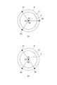
- FIG. 1 shows a case where the displacement sensors 100 are provided at three positions other than the positions facing each other
- FIG. 2B shows the positions facing each other and the positions facing each other. It shows the case where the displacement sensor 100 is provided at the positions other than the above and the three positions.
- a spacer is provided in the vicinity of the bearing of the bearing device 10 for the purpose of adjusting the preload or installing a lubrication mechanism.
- the bearings used in the general bearing device 10 are roughly classified into fixed side bearings and free side bearings, each of which is composed of a single row or a double row.
- the fixed side and the free side mean fixed and free in the axial direction.
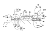
- the bearing device 10 includes a housing 11, a rotating member 21, a front rolling bearing 31, a front outer ring side spacer 36, a front inner ring side spacer 38, a nut 39, and a rear rolling bearing 41. It has a rear outer ring side seat 46, a nut 47, a rear inner ring side seat 48, a drive motor 51, and a displacement sensor 100.
- a hollow rotating member 21 (spindle of a machine tool) is rotatably supported by a front rolling bearing 31 and a rear rolling bearing 41 with respect to a housing 11 which is a fixing member.
- the rotating member 21 is rotationally driven by a drive motor 51 arranged between the front rolling bearing 31 and the rear rolling bearing 41.
- the front side rolling bearing 31 as the front side bearing is provided between the housing 11 and the rotating member 21 in the vicinity of one end (front end) of the rotating member 21 in the axial direction, and is arranged so as to be a back surface combination. It is composed of an angular contact ball bearing 31a as a pair of first front side bearings having substantially the same dimensions and an angular contact ball bearing 31b as a second front side bearing.
- Each of the angular contact ball bearings 31a and 31b is between an outer ring 33 which is a stationary side raceway ring, an inner ring 34 which is a rotating side raceway ring, and an outer ring raceway groove which is a stationary side raceway and an inner ring raceway groove which is a rotating side raceway.
- each of the bearings 31a and 31b has an inner ring 34, an outer ring 33, and a ball 35 rotatably arranged between the inner ring 34 and the outer ring 33.
- Each of the angular contact ball bearings 31a and 31b has an outer ring 33 internally fitted to the housing 11 via an outer ring side spacer 36, and is fixed to the housing 11 by a front bearing outer ring retainer 37 bolted.
- each angular contact ball bearing 31a and 31b is externally fitted to the rotating member 21 via the inner ring side spacer 38, and is fixed to the rotating member 21 by a nut 39 fastened to the rotating member 21.
- the angular contact ball bearings 31a and 31b are loaded with a fixed position preload by the nut 39. Therefore, the position of the rotating member 21 in the rotation axis P direction is positioned by the front rolling bearing 31.
- the front outer ring side spacer 36 includes an intermediate spacer 36a arranged between the pair of angular contact ball bearings 31a and the angular contact ball bearings 31b, and a rear end spacer 36b behind the front rolling bearing 31.
- the front inner ring side spacer 38 is fitted to the rotating member 21 and is arranged between the front end spacer 38a in front of the front rolling bearing 31 and the pair of angular contact ball bearings 31a and the angular contact ball bearing 31b.
- the intermediate portion spacer 38b and the rear end spacer 38c behind the front rolling bearing 31 are provided.
- the radial outer surface (outer peripheral surface) 38d of the intermediate portion spacer 38b faces the displacement sensor 100.
- the radial outer surface 38d of the intermediate seat 38b is referred to as a facing surface.
- the facing surface 38d is a measuring surface for measuring the distance between the displacement sensor 100 and the intermediate seat 38b by the displacement sensor 100.
- the facing surface 38d is arranged behind the angular contact ball bearing 31a, which is the frontmost bearing.
- the position of the facing surface 38d changes due to the radial displacement of the rotating shaft P of the rotating member 21 or the change in the diameter of the rotating member 21.
- the rear rolling bearing 41 as a rear bearing is a cylindrical roller bearing, and is provided between the housing 11 and the rotating member 21 near the other end (rear end) of the rotating shaft P of the rotating member 21 in the axial direction. In addition, it has an outer ring 42, an inner ring 43, and a plurality of cylindrical rollers 44 as rolling elements.
- the outer ring 42 of the rear rolling bearing 41 is fitted in the housing 11 and is fixed in the housing 11 via the outer ring side spacer 46 by the rear bearing retainer 45 bolted to the housing 11.
- the inner ring 43 of the rear rolling bearing 41 is fixed to the rotating member 21 via the inner ring side spacer 48 by a nut 47 fastened to the rotating member 21.
- the rear outer ring side spacer 46 has a front end spacer 46a in front of the bearing 41 and a rear end spacer 46b behind the rear rolling bearing 41.
- the rear inner ring side spacer 48 is fitted to the rotating member 21.
- the rear inner ring side spacer 48 has a front end spacer 48a in front of the rear rolling bearing 41 and a rear end spacer 48b behind the rear rolling bearing 41.
- the drive motor 51 is composed of a stator 52 that is internally fitted in the housing 11 and a rotor 53 that is externally fitted in a rotating member 21 that faces the inner peripheral side of the stator 52 via a gap.
- the displacement sensor 100 is held in the housing 11 and positions positions facing each other on the circumference of a circle R (see FIG. 2A) defined on a plane orthogonal to the rotation axis P of the rotating member 21. It is provided at three or more positions except. That is, in this embodiment, three displacement sensors 100 are provided.
- FIG. 2A illustrates a case where the displacement sensor 100 is provided at three positions S1, S2, and S3 on the circumference of the circle R.
- the angle between the positions S1 and S2 is ⁇ 1
- the angle between the positions S2 and S3 is ⁇ 2
- the angle between the positions S3 and S1 is ⁇ 3.
- the positions S1, S2, and S3 are arranged so that they do not face each other on the circumference of the circle R, for example, each of ⁇ 1, ⁇ 2, and ⁇ 3 is 120 degrees. .. When ⁇ 1 is 180 degrees, S1 and S2 are in positions facing each other.
- the displacement sensor 100 is provided so as to face the facing surface 38d in a direction orthogonal to the rotation axis P of the rotating member 21.
- the displacement sensor 100 measures the distance from the facing surface 38d, and outputs an electric signal corresponding to the measured distance to the axial load measuring unit 101 of the control device 20.
- the displacement sensor 100 is installed on the non-rotating body side of the bearing device 10, and the measurement surface of the displacement sensor 100 faces the rotating body side of the bearing device 10.
- the displacement sensor 100 is a non-contact displacement sensor such as an eddy current displacement sensor, a capacitance displacement sensor, a laser displacement meter, or an air gap sensor.
- the connection between the bearing device 10 and the control device 20 may be a wired connection or a wireless connection.
- control device 20 includes an axial load measuring unit 101, a motor drive circuit 102, and a CPU 103.
- the shaft load measuring unit 101 operates under the control of the CPU 103.
- the shaft load measuring unit 101 receives the detected values of the three displacement sensors 100. More specifically, the axial load measuring unit 101 receives an electric signal corresponding to the distance to each of the three measuring surfaces input from the three displacement sensors 100, and rotates the rotating member 21 based on the electric signal.
- the displacement (misalignment) of the shaft P in the radial direction and the amount of change in the diameter of the rotating member 21 are measured.
- the shaft load measuring unit 101 calculates the shaft load based on the measurement results of the measured displacement (center deviation) of the rotating shaft P in the radial direction and the amount of change in the diameter of the rotating member 21, and outputs the calculation result of the shaft load to the CPU 103. Output.
- the displacement (misalignment) of the rotating shaft P in the radial direction is a deviation of the rotating member 21 from the reference position of the rotating shaft P in a direction orthogonal to the rotating shaft P.
- the change in the diameter of the rotating member 21 is a change in the diameter with respect to the reference diameter of the rotating member 21.
- the motor drive circuit 102 drives the drive motor 51 according to the control of the CPU 103.
- the CPU 103 controls the entire operation of the control device 20 by reading a control program stored in advance in a memory (not shown) and executing the read control program.
- the CPU 103 performs predetermined control based on the calculation result of the shaft load input from the shaft load measuring unit 101.
- the predetermined control is control for the motor drive circuit 102 for reducing the driving force of the drive motor 51, or indicates that it is abnormal when the load amount of the shaft load indicated by the measurement result is equal to or more than the threshold value. It is a control etc. to notify by.
- the control device 20 may have a display unit for displaying that the shaft load is abnormal. Alternatively, the control device 20 may output a signal to an external display device so that the display device displays information or an image regarding the axial load abnormality.
- the control device 20 is not limited to the case of calculating the load amount of the shaft load, but may be limited to calculating the displacement (center deviation) of the rotating shaft P in the radial direction and the amount of change in the diameter of the rotating member 21. ..
- the displacement (misalignment) of the rotating shaft P in the radial direction and the amount of change in the diameter of the rotating member 21 may be displayed on the display device to notify the display device.
- the control device 20 uses the circumscribed circle center method and the inscribed circle center with respect to the amount of radial displacement from the reference circle, with the rotating member 21 of the bearing device 10 rotated and an arbitrary state as a reference circle.
- a measurement circle is calculated from the measured values on the facing surfaces 38d at the three positions using an approximation method such as the method, the minimum region center method, or the minimum self-centered center method. At this time, it is preferable to perform a plurality of measurements in order to improve the measurement accuracy.
- the bearing device 10 is a machine that requires high-speed rotation and high rotation accuracy, its components are also manufactured with high accuracy. Further, the measured displacement amount is very small, about 1/1000 to 1/10000, with respect to the diameter of the measurement circle. From this, since sufficient measurement accuracy can be expected even with only one measurement, the difference between the reference circle and the measurement circle may be obtained instead of the above approximation method. Specifically, the output value of each displacement sensor 100 is used as a reference value or zero offset, and then the difference amount of the output value of each displacement sensor 100 from an arbitrary time point to another time point is measured.
- the average value of each difference amount on each facing surface 38d is the diameter of the facing surface 38d from the rotation axis P (diameter of the circle R shown in FIG. 2) and a predetermined reference circle. It is the amount of change between the diameter and the diameter.
- the displacement vector displacement amount of the rotation axis P is calculated from the difference (binary value) between each difference amount in the displacement sensor 100 at two positions among the displacement sensors 100 at three positions and the average value of each difference amount. calculate. At this time, since the displacement vector displacement amount of the rotation axis P can be calculated by the number of combinations of the displacement sensors 100 at the two positions, the displacement vector with high accuracy can be calculated by using the average value of these displacement vector displacement amounts.
- the amount of displacement can be obtained.
- the numerical value of the diameter of the circle R or the numerical value of the diameter of the rotating member 21 becomes unnecessary when calculating the displacement vector displacement amount and the diameter change amount. It can be calculated only by the measured values of the three displacement sensors 100. More specifically, the amount of change in diameter can be calculated from the measured values of the three displacement sensors 100, and the displacement vector displacement amount can be calculated using any two of the measured values of the three displacement sensors 100. At this time, since three values of the displacement vector displacement amount can be obtained by the combination, the accuracy of the displacement vector displacement amount is improved by averaging them.
- the displacement sensors 100 face each other (for example, in the case of FIG.
- the displacement vector displacement amount can be calculated by the above calculation method, but the displacement sensors 100 of the facing combination (for example, FIG. 2B). Since the displacement vector displacement amount cannot be calculated by the displacement sensors 100) at positions S1 and S2), the obtained displacement vector displacement amount becomes a binary value, and the accuracy is lowered.
- the change in the diameter of the rotating member 21 and the amount of displacement of the rotating shaft P in the radial direction measured by the spindle device 1 of the machine tool are the amount of centrifugal expansion with respect to the reference circle and the temperature difference between the installation position of the displacement sensor 100 and the measurement surface. It is caused by the difference in thermal expansion due to.
- the centrifugal expansion amount is constant at any position, but the difference in thermal expansion amount becomes smaller as the displacement sensor 100 is closer to the bearing because the deviation from the bearing becomes smaller.
- the difference in the amount of thermal expansion can be corrected if the relationship between the temperature rise of the bearing and the temperature rise at the position of the displacement sensor 100 is clarified in advance.
- the displacement sensor 100 is closest to the axial load.
- the amount of change and displacement at the same level as the bearing can be measured, and the distance between the tool end and the bearing (tool end (point of action), which greatly affects the rigidity of the bearing device 10, and the contact angle and rotation of the bearing with respect to the rotating member 21). It is possible to suppress an increase in the intersection point (support point) with the shaft P (distance), and it is possible to accurately measure the temperature change of the bearing due to rotation.
- the front rolling bearing 31 has two rolling bearings (angular contact ball bearings), but the front rolling bearing 31 may be composed of one or three or more rolling bearings.
- the configuration of the spindle device of the machine tool according to the present invention in the second embodiment is the same except that the bearing device 110 is provided instead of the bearing device 10 in FIG. 1, and thus the description thereof will be omitted.
- FIG. 3 the left direction will be described as the front direction and the right direction will be described as the rear direction.
- the description of the lower half of the bearing device 110 is omitted, and the description of the displacement sensor and the control device connected to the drive motor is omitted.
- parts having the same configuration as that of FIG. 1 are designated by the same reference numerals, and the description thereof will be omitted.
- the bearing device 110 includes a rotating member 21, a front rolling bearing 31, a front outer ring side spacer 36, a front inner ring side spacer 38, a nut 39, a rear rolling bearing 41, and a rear outer ring side spacer 46. It has a nut 47, a rear inner ring side bearing 48, a drive motor 51, a displacement sensor 100, and a housing 111.
- a hollow rotating member 21 (spindle shaft) is rotatably supported by a front rolling bearing 31 and a rear rolling bearing 41 with respect to the housing 111 which is a fixing member.
- the front inner ring side spacer 38 is fitted to the rotating member 21.
- the front inner ring side spacer 38 includes a front end spacer 38a in front of the front rolling bearing 31, an intermediate spacer 38b arranged between the pair of angular contact ball bearings 31a and the angular contact ball bearing 31b, and front rolling. It is provided with a rear end spacer 38c behind the bearing 31.
- the radial outer surface (outer peripheral surface) 38e of the rear end spacer 38c faces the displacement sensor 100.
- the radial outer surface 38e of the rear end spacer 38c is referred to as a facing surface.
- the facing surface 38e is a measuring surface for measuring the distance between the displacement sensor 100 and the rear end spacer 38c by the displacement sensor 100.
- the facing surface 38e is arranged behind the angular contact ball bearing 31a, which is the frontmost bearing.
- the position of the facing surface 38e changes due to the displacement (misalignment) of the rotating shaft P in the radial direction or the change in the diameter of the rotating member 21.
- the displacement sensor 100 is held in the housing 111, is located on the rear end side of the axial direction P with respect to the angular contact ball bearing 31b, and is located on the rear end spacer 38c of the front inner ring side spacer 38 closest to the drive motor 51. It is provided at three or more positions on the circumference of a circle defined on a plane orthogonal to the rotation axis P of the rotating member 21 to be located.
- the displacement sensor 100 is provided so as to face the facing surface 38e in a direction orthogonal to the rotation axis P of the rotating member 21.
- the displacement sensor 100 measures the distance from the facing surface 38e and outputs an electric signal corresponding to the measured distance to the axial load measuring unit 101 of the control device 20.
- the displacement sensor 100 is installed on the non-rotating body side of the bearing device 110, and the measurement surface of the displacement sensor 100 faces the rotating body side of the bearing device 110.
- control device according to the present embodiment has the same configuration as that in FIG. 1, the description thereof will be omitted. Further, since the operation of the bearing device 110 is the same as that of the bearing device 10 according to the first embodiment, the description thereof will be omitted.
- the front rolling bearing 31 and the rear rolling bearing 41 depending on the degree of heat generation of the front rolling bearing 31 itself or the rear rolling bearing 41 itself, or the degree of heat generation or heat dissipation from the drive motor 51, the front rolling bearing 31 and the rear rolling bearing 41
- the outer ring 33 and the outer ring 42 on the non-rotating body side of the bearing device 10 in the vicinity of the drive motor 51 are thermally the most severe.
- the facing surface 38e of the rear end spacer 38c of the front inner ring bearing 38 which is thermally harsh, is used as the measurement surface of the displacement sensor 100, so that not only the machining load but also the machining load is added.
- the configuration of the spindle device of the machine tool according to the present invention in the third embodiment is the same except that the bearing device 210 is provided instead of the bearing device 10 in FIG. 1, and thus the description thereof will be omitted.
- FIG. 4 the left direction will be described as the front direction and the right direction will be described as the rear direction.
- the description of the lower half of the bearing device 210 is omitted, and the description of the displacement sensor and the control device connected to the drive motor is omitted.
- parts having the same configuration as that of FIG. 1 are designated by the same reference numerals, and the description thereof will be omitted.
- the bearing device 210 includes a rotating member 21, a front rolling bearing 31, a front outer ring side spacer 36, a front inner ring side spacer 38, a nut 39, a rear rolling bearing 41, and a rear outer ring side spacer 46. It has a nut 47, a rear inner ring side bearing 48, a drive motor 51, a displacement sensor 100, and a housing 211.
- a hollow rotating member 21 (spindle shaft) is rotatably supported by a front rolling bearing 31 and a rear rolling bearing 41 with respect to the housing 211 which is a fixing member.
- the rear inner ring side spacer 48 is fitted to the rotating member 21.
- the radial outer surface (outer peripheral surface) 48c of the rear end spacer 48b of the rear inner ring side spacer 48 faces the displacement sensor 100.
- the radial outer surface 48c of the rear end spacer 48b is referred to as a facing surface.
- the facing surface 48c is a measuring surface for measuring the distance between the displacement sensor 100 and the rear end spacer 48b by the displacement sensor 100.
- the facing surface 48c is arranged behind the angular contact ball bearing 31a, which is the frontmost bearing. The position of the facing surface 48c changes due to the displacement (misalignment) of the rotating shaft P in the radial direction or the change in the diameter of the rotating member 21.
- the displacement sensor 100 is installed in the vicinity of the rear rolling bearing 41, which is a free bearing.
- the displacement sensor 100 is held in the housing 211, and is provided at three or more positions on the circumference of a circle defined on a plane orthogonal to the rotation axis P of the rotating member 21.
- the displacement sensor 100 is provided so as to face the facing surface 48c in a direction orthogonal to the rotation axis P of the rotating member 21.
- the displacement sensor 100 measures the distance from the facing surface 48c and outputs an electric signal corresponding to the measured distance to the axial load measuring unit 101 of the control device 20.
- the displacement sensor 100 is installed on the non-rotating body side of the bearing device 210, and the measurement surface of the displacement sensor 100 faces the rotating body side of the bearing device 210.
- control device according to the present embodiment has the same configuration as that in FIG. 1, the description thereof will be omitted. Further, since the operation of the bearing device 210 is the same as that of the bearing device 10 according to the first embodiment, the description thereof will be omitted.
- the displacement sensor 100 by arranging the displacement sensor 100 in the vicinity of the rear rolling bearing 41, the axial displacement vector of the rotating shaft P of the rotating member 21 and the change in the diameter of the rotating member 21 can be obtained. Can be measured.
- the configuration of the spindle device of the machine tool according to the present invention in the fourth embodiment is the same except that the bearing device 310 is provided instead of the bearing device 10 in FIG. 1, and thus the description thereof will be omitted.
- FIG. 5 the left direction will be described as the front direction and the right direction will be described as the rear direction.
- the description of the lower half of the bearing device 310 is omitted, and the description of the control device connected to the displacement sensor and the drive motor is omitted.
- the parts having the same configuration as that of FIG. 1 are designated by the same reference numerals, and the description thereof will be omitted.
- the bearing device 310 includes a rotating member 21, a front rolling bearing 31, a front outer ring side spacer 36, a front inner ring side spacer 38, a nut 39, a rear rolling bearing 41, and a rear outer ring side spacer 46. It has a nut 47, a rear inner ring side bearing 48, a drive motor 51, a displacement sensor 100, and a housing 311.
- a hollow rotating member 21 (spindle shaft) is rotatably supported by a front rolling bearing 31 and a rear rolling bearing 41 with respect to the housing 311 which is a fixing member.
- the rotating member 21 is rotationally driven by a drive motor 51 arranged between the front rolling bearing 31 and the rear rolling bearing 41.
- the rear inner ring side spacer 48 is fitted to the rotating member 21.
- the radial outer surface (outer peripheral surface) 48d of the front end spacer 48a of the rear inner ring side spacer 48 faces the displacement sensor 100.
- the radial outer surface 48d of the front end spacer 48a is referred to as a facing surface.
- the facing surface 48d is a measuring surface for measuring the distance between the displacement sensor 100 and the front end spacer 48a by the displacement sensor 100.
- the facing surface 48d is arranged behind the angular contact ball bearing 31a, which is the frontmost bearing. The position of the facing surface 48d changes due to the displacement (misalignment) of the rotating shaft P in the radial direction or the change in the diameter of the rotating member 21.
- the displacement sensor 100 is installed in the vicinity of the rear rolling bearing 41, which is a free bearing.
- the displacement sensor 100 is held in the housing 311 and is provided at three or more positions on the circumference of a circle defined on a plane orthogonal to the rotation axis P of the rotating member 21.
- the displacement sensor 100 is provided so as to face the facing surface 48d in a direction orthogonal to the rotation axis P of the rotating member 21.
- the displacement sensor 100 measures the distance from the facing surface 48d, and outputs an electric signal corresponding to the measured distance to the axial load measuring unit 101 of the control device 20.
- the displacement sensor 100 is installed on the non-rotating body side of the bearing device 310, and the measurement surface of the displacement sensor 100 faces the rotating body side of the bearing device 310.
- control device Since the control device according to the present embodiment has the same configuration as that in FIG. 1, the description thereof will be omitted. Further, since the operation of the bearing device 310 is the same as that of the bearing device 10 according to the first embodiment, the description thereof will be omitted.
- the amount of heat flowing from the drive motor 51 to the rear rolling bearing 41 can be easily estimated by setting the position closer to the drive motor 51 than the rear rolling bearing 41 as the measurement surface of the displacement sensor 100. ..
- the configuration of the spindle device of the machine tool according to the present invention in the fifth embodiment is the same except that the bearing device 410 is provided instead of the bearing device 10 in FIG. 1, and thus the description thereof will be omitted.
- FIG. 6 the left direction will be described as the front direction and the right direction will be described as the rear direction.
- a part of the bearing device 410 is shown, and the description of the displacement sensor and the control device connected to the drive motor is omitted.
- the parts having the same configuration as that of FIG. 1 are designated by the same reference numerals, and the description thereof will be omitted.
- the bearing device 410 includes a rotating member 21, a nut 39, a rear rolling bearing 41, a rear outer ring side spacer 46, a nut 47, a rear inner ring side spacer 48, a drive motor 51, and a displacement sensor. It has 100, a housing 411, a front rolling bearing 431, a front outer ring side spacer 436, and a front inner ring side spacer 438.
- the hollow rotating member 21 (spindle shaft) is rotatably supported by the front rolling bearing 431 and the rear rolling bearing 41 with respect to the housing 411 which is a fixing member.
- the rotating member 21 is rotationally driven by a drive motor 51 arranged between the front rolling bearing 431 and the rear rolling bearing 41.
- the front rolling bearing 431 is provided between the housing 411 and the rotating member 21, and is composed of a pair of angular contact ball bearings 431a and 431b arranged so as to be a back combination.
- Each of the angular contact ball bearings 431a and 431b is between an outer ring 433 which is a stationary side raceway ring, an inner ring 434 which is a rotating side raceway ring, and an outer ring raceway groove which is a stationary side raceway and an inner ring raceway groove which is a rotating side raceway.
- It is provided with a plurality of balls 435 as rolling elements arranged with a contact angle. That is, each bearing 431a and 431b has an inner ring 434, an outer ring 433, and a ball 435 rotatably arranged between the inner ring 434 and the outer ring 433.
- Each angular contact ball bearing 431a and 431b has an outer ring 433 fitted inside the housing 411 via an outer ring side spacer 436, and is fixed to the housing 411 by a front bearing outer ring retainer 37 bolted.
- each angular contact ball bearing 431a and 431b is fitted onto the rotating member 21 via the inner ring side spacer 438, and is fixed to the rotating member 21 by a nut 39 fastened to the rotating member 21. Therefore, the position of the rotating member 21 in the rotation axis P direction is positioned by the front rolling bearing 431.
- the inner ring 434 of the angular contact ball bearing 431a extends rearward from the outer ring 433 of the angular contact ball bearing 431a.
- the radial outer surface (outer peripheral surface) 434a of the inner ring 434 of the angular contact ball bearing 431a faces the displacement sensor 100.
- the radial outer surface 434a of the inner ring 434 of the angular contact ball bearing 431a is referred to as a facing surface.
- the facing surface 434a is a measuring surface for measuring the distance between the displacement sensor 100 and the inner ring 434 of the angular contact ball bearing 431a by the displacement sensor 100.
- the facing surface 434a is arranged behind the angular contact ball bearing 431a, which is the frontmost bearing.
- the position of the facing surface 434a changes due to the radial displacement (misalignment) of the rotating shaft P or the change in the diameter of the rotating member 21.
- the front outer ring side spacer 436 includes an intermediate spacer 436a arranged between the pair of angular contact ball bearings 431a and the angular contact ball bearings 431b, and a rear end spacer 436b behind the front rolling bearing 431.
- the front inner ring side spacer 438 is fitted to the rotating member 21.
- the front inner ring side spacer 438 includes a front end spacer 438a in front of the front rolling bearing 431, an intermediate spacer 438b arranged between the pair of angular contact ball bearings 431a and the angular contact ball bearing 431b, and a front rolling bearing 438b. It is provided with a rear end spacer 438c behind the bearing 431.
- the displacement sensor 100 is provided so as to face the facing surface 434a in a direction orthogonal to the rotation axis P of the rotating member 21.
- the displacement sensor 100 measures the distance from the facing surface 434a and outputs an electric signal corresponding to the measured distance to the axial load measuring unit 101 of the control device 20.
- the displacement sensor 100 is installed on the non-rotating body side of the bearing device 410, and the measurement surface of the displacement sensor 100 faces the rotating body side of the bearing device 410.
- control device Since the control device according to the present embodiment has the same configuration as that in FIG. 1, the description thereof will be omitted. Further, since the operation of the bearing device 410 is the same as that of the bearing device 10 according to the first embodiment, the description thereof will be omitted.
- the change in the diameter of the inner ring 434 of the front rolling bearing 431 can be measured more accurately.
- FIG. 6 the left direction will be described as the front direction and the right direction will be described as the rear direction.
- a part of the bearing device 410 is shown, and the description of the displacement sensor and the control device connected to the drive motor is omitted.
- the parts having the same configuration as that of FIG. 1 are designated by the same reference numerals, and the description thereof will be omitted.
- the bearing device 510 includes a rotating member 21, a nut 39, a rear rolling bearing 41, a rear outer ring side spacer 46, a nut 47, a rear inner ring side spacer 48, a drive motor 51, and a displacement sensor. It has 500, a housing 511, a front rolling bearing 531, a front outer ring side spacer 536, and a front inner ring side spacer 538.
- the hollow rotating member 21 (spindle shaft) is rotatably supported by the front rolling bearing 531 and the rear rolling bearing 41 with respect to the housing 511 which is a fixing member.
- the rotating member 21 is rotationally driven by a drive motor 51 arranged between the front rolling bearing 531 and the rear rolling bearing 41.
- the front rolling bearing 531 is composed of a pair of angular contact ball bearings 531a and 531b provided between the housing 511 and the rotating member 21 and arranged so as to be a back combination.
- Each of the angular contact ball bearings 531a and 531b is between an outer ring 533 which is a stationary side raceway ring, an inner ring 534 which is a rotating side raceway ring, and an outer ring raceway groove which is a stationary side raceway and an inner ring raceway groove which is a rotating side raceway.
- It is provided with a plurality of balls 535 as rolling elements arranged with a contact angle. That is, each of the bearings 531a and 531b has an inner ring 534, an outer ring 533, and a ball 535 rotatably arranged between the inner ring 534 and the outer ring 533.
- Each of the angular contact ball bearings 531a and 531b has an outer ring 533 fitted inside the housing 511 via an outer ring side spacer 536, and is fixed to the housing 511 by a front bearing outer ring retainer 37 bolted to the housing 511.
- each angular contact ball bearing 531a and 531b is externally fitted to the rotating member 21 via the inner ring side spacer 538, and is fixed to the rotating member 21 by a nut 39 fastened to the rotating member 21. Therefore, the position of the rotating member 21 in the rotation axis P direction is positioned by the front rolling bearing 531.
- Each of the outer ring 533 and the inner ring 534 of the angular contact ball bearing 531a has a longer length in the rotation axis P direction than each of the outer ring 533 and the inner ring 534 of the angular contact ball bearing 531b.
- the outer ring 533 of the angular contact ball bearing 531a holds the displacement sensor 500.
- the radial outer surface (outer peripheral surface) 534a of the inner ring 534 faces the displacement sensor 500.
- the radial outer surface 534a of the inner ring 534 of the angular contact ball bearing 531a is referred to as a facing surface.
- the facing surface 534a is a measuring surface for measuring the distance between the displacement sensor 500 and the inner ring 534 of the angular contact ball bearing 531a by the displacement sensor 100.
- the facing surface 534a is arranged behind the angular contact ball bearing 531a, which is the frontmost bearing. The position of the facing surface 534a changes due to the radial displacement (misalignment) of the rotating shaft P or the change in the diameter of the rotating member 21.
- the front outer ring side spacer 536 is fitted to the rotating member 21.
- the front outer ring side spacer 536 includes an intermediate spacer 536a arranged between the pair of angular contact ball bearings 531a and the angular contact ball bearings 531b, and a rear end spacer 536b behind the front rolling bearing 531.
- the front inner ring side spacer 538 is fitted to the rotating member 21.
- the front inner ring side spacer 538 includes a front end spacer 538a in front of the front rolling bearing 531, an intermediate spacer 538b arranged between the pair of angular contact ball bearings 531a and the angular contact ball bearing 531b, and front rolling. It is provided with a rear end spacer 538c behind the bearing 531.
- the displacement sensors 500 are provided at three or more positions on the circumference of a circle defined on a plane orthogonal to the rotation axis P of the rotating member 21. That is, in this embodiment, three displacement sensors 500 are provided.
- the displacement sensor 500 is removably fitted with the first connector 500a held by the outer ring 533 of the angular contact ball bearing 531a and the first connector 500a, and is connected to the control device 20 through the housing 511. It has a second connector 500b and the like.
- the first connector 500a of the displacement sensor 500 is provided so as to face the facing surface 534a in the direction orthogonal to the rotation axis P of the rotating member 21.
- the displacement sensor 500 measures the distance from the facing surface 534a and outputs an electric signal corresponding to the measured distance to the axial load measuring unit 101 of the control device 20.
- the displacement sensor 500 is installed on the non-rotating body side of the bearing device 510, and the measurement surface of the displacement sensor 500 faces the rotating body side of the bearing device 510.
- the displacement sensor 500 is a non-contact displacement sensor such as an eddy current displacement sensor, a capacitance displacement sensor, a laser displacement meter, or an air gap sensor.
- control device Since the control device according to the present embodiment has the same configuration as that in FIG. 1, the description thereof will be omitted. Further, since the operation of the bearing device 510 is the same as that of the bearing device 10 according to the first embodiment, the description thereof will be omitted.
- the displacement sensor 500 is held by the outer ring 533 of the angular contact ball bearing 531a, and the displacement sensor 500 and the outer ring 533 are integrated to adjust the gap amount between the displacement sensor 500 and the facing surface 534a in advance. Can be kept.
- the housing when measuring the axial displacement vector of the rotating shaft P of the rotating member 21 and the change in the diameter of the rotating member 21. The influence of the displacement that occurs between the 511 and the outer ring 533 can be avoided.
- the displacement sensor 500 when the displacement sensor 500 and the control device 20 are connected by wire, the displacement sensor 500 is a connector type, and the first connector 500a is held by the outer ring 533 and assembled, and then the second one is assembled. Since the connector 500b can be connected, the displacement sensor 500 can be installed without disconnecting the signal line connecting the displacement sensor 500 and the control device 20.
- the facing surface 534a of the inner ring 534 as the measurement surface, it is possible to strictly measure the change in the diameter of the inner ring 534 of the front rolling bearing 531.
- the configuration of the spindle device of the machine tool according to the present invention in the seventh embodiment is the same except that the bearing device 610 is provided instead of the bearing device 10 in FIG. 1, and thus the description thereof will be omitted.
- FIG. 8 the left direction will be described as the front direction and the right direction will be described as the rear direction.
- a part of the bearing device 610 is shown, and the description of the control device connected to the displacement sensor and the drive motor is omitted.
- the parts having the same configuration as that of FIG. 1 are designated by the same reference numerals, and the description thereof will be omitted.
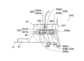
- the bearing device 610 includes a rotating member 21, a nut 39, a rear rolling bearing 41, a rear outer ring side spacer 46, a nut 47, a rear inner ring side spacer 48, a drive motor 51, and a displacement sensor. It has 600, a housing 611, a front rolling bearing 631, a front outer ring side spacer 636, and a front inner ring side spacer 638.
- a hollow rotating member 21 (spindle shaft) is rotatably supported by a front rolling bearing 631 and a rear rolling bearing 41 with respect to a housing 611 which is a fixing member.
- the rotating member 21 is rotationally driven by a drive motor 51 arranged between the front rolling bearing 631 and the rear rolling bearing 41.
- the front rolling bearing 631 is provided between the housing 611 and the rotating member 21, and is composed of a pair of angular contact ball bearings 631a and 631b arranged so as to be a back combination.
- Each of the angular contact ball bearings 631a and 631b is between an outer ring 633 which is a stationary side raceway ring, an inner ring 634 which is a rotating side raceway ring, and an outer ring raceway groove which is a stationary side raceway and an inner ring raceway groove which is a rotating side raceway.
- It is provided with a plurality of balls 635 as rolling elements arranged with a contact angle. That is, each of the bearings 631a and 631b has an inner ring 634, an outer ring 633, and a ball 635 rotatably arranged between the inner ring 634 and the outer ring 633.
- the outer ring 633 is internally fitted into the housing 611 via the outer ring side spacer 636, and the angular contact ball bearings 631a and 631b are fixed to the housing 611 by the front bearing outer ring retainer 37 bolted.
- each angular contact ball bearing 631a and 631b is externally fitted to the rotating member 21 via the inner ring side spacer 638, and is fixed to the rotating member 21 by a nut 39 fastened to the rotating member 21. Therefore, the position of the rotating member 21 in the rotation axis P direction is positioned by the front rolling bearing 631.
- the outer ring 633 of the angular contact ball bearing 631a extends rearward from the inner ring 634 of the angular contact ball bearing 631a and holds the displacement sensor 600.
- the front outer ring side spacer 636 includes an intermediate spacer 636a arranged between the pair of angular contact ball bearings 631a and the angular contact ball bearing 631b, and a rear end spacer 636b behind the front rolling bearing 631.
- the front inner ring side spacer 638 is fitted to the rotating member 21.
- the front inner ring side spacer 638 includes a front end spacer 638a in front of the front rolling bearing 631, an intermediate spacer 638b arranged between the pair of angular contact ball bearings 631a and the angular contact ball bearing 631b, and a front rolling bearing 631b. It is provided with a rear end spacer 638c behind the bearing 631.
- the radial outer surface (outer peripheral surface) 638d of the intermediate portion spacer 638b faces the displacement sensor 600. In the following description, the radial outer surface 638d of the intermediate portion spacer 638b is referred to as a facing surface.
- the facing surface 638d is a measuring surface for measuring the distance between the displacement sensor 600 and the intermediate seat 638b by the displacement sensor 600.
- the facing surface 638d is arranged behind the angular contact ball bearing 631a, which is the frontmost bearing. The position of the facing surface 638d changes due to the radial displacement (misalignment) of the rotating shaft P or the change in the diameter of the rotating member 21.
- the displacement sensors 600 are provided at three or more positions on the circumference of a circle defined on a plane orthogonal to the rotation axis P of the rotating member 21. That is, in this embodiment, three displacement sensors 600 are provided.
- the displacement sensor 600 is removably fitted with the first connector 600a held by the outer ring 633 of the angular contact ball bearing 631a and the first connector 600a, and is connected to the control device 20 through the housing 611. It has a second connector 600b and the like.
- the first connector 600a of the displacement sensor 600 is provided so as to face the facing surface 638d in the direction orthogonal to the rotation axis P of the rotating member 21.
- the displacement sensor 600 measures the distance from the facing surface 638d and outputs an electric signal corresponding to the measured distance to the axial load measuring unit 101 of the control device 20.
- the displacement sensor 600 is installed on the non-rotating body side of the bearing device 610, and the measurement surface of the displacement sensor 600 faces the rotating body side of the bearing device 610.
- the displacement sensor 600 is a non-contact displacement sensor such as an eddy current displacement sensor, a capacitance displacement sensor, a laser displacement meter, or an air gap sensor.
- control device Since the control device according to the present embodiment has the same configuration as that in FIG. 1, the description thereof will be omitted. Further, since the operation of the bearing device 610 is the same as that of the bearing device 10 according to the first embodiment, the description thereof will be omitted.
- the gap amount between the displacement sensor 600 and the facing surface 638d can be adjusted in advance by holding the displacement sensor 600 on the outer ring 633 of the angular contact ball bearing 631a.
- the housing when measuring the axial displacement vector of the rotating shaft P of the rotating member 21 and the change in the diameter of the rotating member 21. The influence of the displacement that occurs between the 611 and the outer ring 633 can be avoided.
- the configuration of the spindle device of the machine tool according to the present invention in the eighth embodiment is the same except that the bearing device 710 is provided instead of the bearing device 10 in FIG. 1, and thus the description thereof will be omitted.
- FIG. 9 the left direction will be described as the front direction and the right direction will be described as the rear direction.
- a part of the bearing device 710 is shown, and the description of the displacement sensor and the control device connected to the drive motor is omitted.
- the parts having the same configuration as that of FIG. 1 are designated by the same reference numerals, and the description thereof will be omitted.
- the bearing device 710 includes a rotating member 21, a front rolling bearing 31, a front outer ring side spacer 36, a nut 39, a rear rolling bearing 41, a rear outer ring side spacer 46, a nut 47, and a rear side. It has an inner ring side bearing 48, a drive motor 51, a displacement sensor 100, a housing 711, and a front inner ring side bearing 738.
- the bearing device 710 has a hollow rotating member 21 with respect to the housing 711, which is a fixing member. (Spindle shaft) is rotatably supported by a front rolling bearing 31 and a rear rolling bearing 41.
- the rotating member 21 is rotationally driven by a drive motor 51 arranged between the front rolling bearing 31 and the rear rolling bearing 41.
- the radial outer surface (outer peripheral surface) 21a of the rotating member 21 faces the displacement sensor 100.
- the radial outer surface 21a of the rotating member 21 is referred to as a facing surface.
- the facing surface 21a is a measuring surface for measuring the distance between the displacement sensor 100 and the rotating member 21 by the displacement sensor 100.
- the facing surface 21a is arranged behind the angular contact ball bearing 31a, which is the frontmost bearing. The position of the facing surface 21a changes due to the displacement (misalignment) of the rotating shaft P in the radial direction or the change in the diameter of the rotating member 21.
- the front inner ring side spacer 738 is fitted to the rotating member 21.
- the front inner ring side spacer 738 includes a front end spacer 738a in front of the front rolling bearing 31, and an intermediate spacer 738b arranged between the pair of angular contact ball bearings 31a and the angular contact ball bearings 31b. ing.
- the displacement sensor 100 is held in the housing 711 and is provided at three or more positions on the circumference of a circle defined on a plane orthogonal to the rotation axis P of the rotating member 21.
- the displacement sensor 100 is provided so as to face the facing surface 21a in a direction orthogonal to the rotation axis P of the rotating member 21.
- the displacement sensor 100 measures the distance from the facing surface 21a and outputs an electric signal corresponding to the measured distance to the axial load measuring unit 101 of the control device 20.
- the displacement sensor 100 is installed on the non-rotating body side of the bearing device 710, and the measurement surface of the displacement sensor 100 faces the rotating body side of the bearing device 710.
- control device Since the control device according to the present embodiment has the same configuration as that in FIG. 1, the description thereof will be omitted. Further, since the operation of the bearing device 610 is the same as that of the bearing device 10 according to the first embodiment, the description thereof will be omitted.
- the number of constituent elements can be reduced to make a simple configuration, and the spacer and the rotating member 21 are fitted to each other when the gap is fitted. It is possible to eliminate the influence of the error of the gap amount between the displacement sensor 100 and the measuring surface 21a due to the deviation between the rotating member and the rotating shaft P of the rotating member.
- the spindle device 200 of the machine tool has a pressure loss measuring unit 221, a compressed gas supply unit 230, a bearing device 240, an arithmetic processing unit PU, and a display unit DP.
- the spindle device 200 of the machine tool supplies the displacement detection unit 201 for detecting the radial displacement of the rotating member 21 using the compressed gas and the displacement detection unit 201 to supply the compressed gas to the front outer ring side.
- a pressure loss measuring unit 221 for measuring the pressure loss according to the gap between the spacer 36 and the front inner ring side spacer 38 is provided as a set.
- a plurality of sets (here, two sets) of the displacement detection unit 201 and the pressure loss measurement unit 221 are provided in the circumferential direction.
- the displacement measuring unit 200 includes an arithmetic processing unit PU that calculates the amount of load acting on the rotating member 21 based on the measurement results of each pressure loss measuring unit 221.
- the displacement detection unit 201 is provided in three or more directions on the circumference of the circle R defined on the plane orthogonal to the rotation axis P of the rotating member 21.
- the displacement detection unit 201 can be arranged at any position in the rotation axis P direction of the rotating member 21. More preferably, it is arranged near the rear of the front row bearing.
- Each of the displacement detection units 201 includes a front outer ring side spacer 36 and a front inner ring side spacer 38 of the front rolling bearing 31. That is, the front outer ring side spacer 36 has an outer peripheral side ring portion 36a that contacts the axial end faces of the outer ring 33 of the angular contact ball bearings 31a and 31b and the inner peripheral side ring portion that is narrower than the outer peripheral side ring portion 36a. It is equipped with 36b.
- the outer peripheral side ring portion 36a is formed with a recess 36c recessed from the outside to the inside in the central portion in the axial direction.
- the inner peripheral surface of the inner peripheral side ring portion 36b faces the outer peripheral surface of the front inner ring side spacer 38 so as to form a predetermined gap g to be measured.
- a funnel-shaped compressed gas discharge nozzle 202 extending radially from the bottom of the recess 36c of the outer peripheral side ring portion 36a to the inner peripheral surface is formed, and the compressed gas is discharged from the compressed gas discharge nozzle 202 to the front outer ring side spacer 36 and It is discharged into the measurement gap g between the front inner ring side spacers 38.
- the spindle shaft of a machine tool is a hollow shaft because a drawbar is provided in the inner diameter of the shaft as a mechanism for gripping a tool, and the spindle shaft is rotated at high speed in order to improve machining efficiency. It is assumed that. Therefore, particularly when high-speed rotation is used, the rotating members 21, the front inner ring side spacer 38, and the like expand by several to several tens of ⁇ m due to centrifugal force. Further, during the rotation of the spindle, a temperature difference occurs between the housing 241 and the rotating member 21, and in many cases, the rotating member 21 is higher. Therefore, the amount of gap between the housing 241 and the rotating member 21 is several to several tens of ⁇ m. It becomes smaller.
- a gap formed between the housing 241 and the rotating member 21, such as between the front outer ring side spacer 36 and the front inner ring side spacer 38, allows foreign matter to enter the inside of the spindle or the rolling bearing 31. In order to prevent this, it is set to a few mm at the maximum.
- the gap g to be measured between the front outer ring side spacer 36 and the front inner ring side spacer 38 is set to 0.05 mm to 0.5 mm when the rotating member 21 is stationary, but the radial displacement of the rotating member 21 is set. Since the amount of change in the pressure loss with respect to the relative value increases as the amount of the gap decreases, it is preferable to set the gap g to be measured to 0.05 mm to 0.2 mm.
- the front inner ring side spacer 38 provided in the displacement detection unit 201 is a rotating member 21 as much as possible. It is desirable to be coaxial with. Therefore, it is desirable that the front inner ring side spacer 38 is fitted to the shaft by an intermediate fit or a tighten fit.
- the housing 241 is formed with a circular opening 203 coaxially with the compressed gas discharge nozzle 202, reaching the recess 36c of the front outer ring side spacer 36 from the outer peripheral surface and reducing the inner diameter in two steps.
- one end of the compressed gas supply passage 204 formed on the rear side wall is opened in the opening 203.
- the other end of the compressed gas supply passage 204 communicates with the compressed gas supply passage 205 formed by opening to the rear end formed in the housing 241 and extending forward in the axial direction. ..
- the direction of the compressed gas supplied from the compressed gas supply passage 204 is changed from the axial direction to the radial direction in the opening 203, and the compressed gas is discharged.
- a gas connecting portion 206 as a gas direction changing portion supplied to the nozzle 202 is mounted.
- the gas connecting portion 206 has a shape that can be fitted into the opening 203, for example, an outer peripheral shape having the same shape as the inner peripheral shape of the opening 203, and internally communicates with the opening 203 into the gas passage 66a and the gas passage 66a.
- a gas passage 66b is formed in which one end communicates with the compressed gas discharge nozzle 202 and the other end communicates with the compressed gas discharge nozzle 202.
- An O-ring 67 is arranged between the side wall of the gas connection portion 206 and the inner wall of the opening 203, and an O-ring 68 is similarly arranged between the bottom surface of the gas connection portion 206 and the bottom surface of the recess 36c. O-rings 67 and 68 prevent the leakage of compressed air.
- the gas connecting portion 206 is positioned in the radial direction by the stepped portion of the outer peripheral surface coming into contact with the stepped portion of the inner peripheral surface of the opening 203. There is. Further, the gas connection portion 206 is prevented from coming out of the opening 203 by contacting the holding piece 209 whose end surface on the outer side in the radial direction is screwed to the outer peripheral surface of the housing 241.
- the gas connection portion 206 is not limited to the case where the holding piece 209 prevents the gas connection portion 206 from coming off, and a flange portion can be formed on the outer peripheral surface side of the gas connection portion 206 and the flange portion can be screwed to the gas connection portion 206.
- the fixing method of 206 to the housing 241 can be any fixing method.
- the pressure loss measuring unit 221 is compressed from the compressed gas supply unit 230 to a lubrication system by oil-air lubrication or oil mist lubrication (not shown) that supplies lubricating oil to the front rolling bearing 31 and the rear rolling bearing 41.
- Gas is supplied.
- the compressed gas supply unit 230 includes a compressor 231 that discharges compressed gas, a regulator 232 for a lubrication system that regulates the pressure of the compressed gas discharged from the compressor 231, and a regulator 233 for pressure loss measurement that is connected in parallel with the regulator 232. And have.
- the first embodiment is not limited to oil-air lubrication and oil mist lubrication. For example, it can also be applied to grease lubrication. Lubricants and greases are examples of lubricants.
- the lubrication system is a lubricant supply unit that supplies the lubricant to the bearings 31 and 41.
- the pressure loss measuring unit 221 includes a throttle 222 inserted in the compressed gas supply path and a differential pressure sensor 223 that detects the differential pressure on the upstream side and the downstream side of the throttle.
- the throttle 222 is inserted in a pipe 224 that connects the regulator 233 and the opening of the compressed gas supply passage 205 formed in the housing 241.
- the throttle amount of the throttle 222 is set so that the differential pressure detection value detected by the differential pressure sensor 223 when the radial displacement of the rotating member 21 is “0” during the rotation of the rotating member 21 becomes a preset value. Set to.
- the pressure on the downstream side of the throttle 222 represents the pressure loss corresponding only to the radial displacement of the rotating member 21 in consideration of the flow path resistance due to the pipe length and the pipe diameter from the throttle 222 to the displacement detection unit 201. Become.
- the low pressure side is connected to the pipe 224 on the downstream side of the throttle 222, and the high pressure side is connected to the regulator 233 via the pipe 225.
- the differential pressure between the compressed air pressure supplied from the regulator 233 and the downstream pressure of the throttle 222 connected to the displacement detection unit 201 that is, the pressure loss according to the displacement of the rotating member 21 in the displacement detection unit 201. Is detected, and the detected differential pressure detection value is output as an analog value or a digital value.
- the arithmetic processing unit PU is composed of an arithmetic processing device such as a microcomputer, for example, a differential pressure detection value output from the differential pressure sensor 223 of each pressure loss measurement unit 221 is input, and rotation is performed based on the differential pressure detection value.
- the converted displacement amount of the member 21 in the radial direction is calculated.
- the arithmetic processing unit PU multiplies the calculated displacement amount of the rotating member 21 in the radial direction by the axial rigidity value at the axial position of the compressed gas discharge nozzle 202 calculated in advance, so that the load applied to the rotating member 21 is applied.
- the amount is calculated, and the calculation result is output to the display DP and displayed.
- the shaft rigidity value is calculated based on the load point, the bearing position of the front rolling bearing 31, the bearing rigidity, the shaft rigidity, the axial position of the compressed gas discharge nozzle 202 of the displacement detection unit 201, and the like.
- the amount of load applied to the rotating member 21 is not limited to the case of calculating by the above-mentioned calculation.
- a known load is applied to the rotating member 21, and the differential pressure detection value output from the differential pressure sensor 223 of the pressure loss measuring unit 221 at that time is repeatedly measured to obtain the load and the differential pressure detection value.
- a load calculation map showing the relationship between the above is created, and this is stored in the storage unit of the arithmetic processing unit PU.
- the load amount can be calculated directly from the differential pressure detection value by referring to the load calculation map based on the differential pressure detection value detected by the differential pressure sensor 223 at the time of cutting.
- the load amount can be calculated by obtaining the equation of the characteristic line of the load calculation map and substituting the differential pressure detection value of the differential pressure sensor 223 into the obtained equation. ..
- each pressure loss measurement unit 221 is connected in parallel to the regulator 233 as shown in FIG. ..
- the bearing device 240 includes a rotating member 21, a front rolling bearing 31, a front outer ring side spacer 36, a front inner ring side spacer 38, a nut 39, a rear rolling bearing 41, and a rear outer ring side spacer 46. It has a nut 47, a rear inner ring side bearing 48, a drive motor 51, and a housing 241.
- the housing 241 is composed of a front cylindrical portion 242 and a rear cylindrical portion 243 that are divided into two parts between the front rolling bearing 31 and the drive motor 51.
- the front cylindrical portion 242 is composed of a small outer diameter portion 242a on the front side having a small outer diameter and a large outer diameter portion 242b on the rear side having a larger outer diameter than the small outer diameter portion 242a.
- the inner peripheral surfaces of the small outer diameter portion 242a and the large outer diameter portion 242b are formed to have the same inner diameter, but a bearing storage step for accommodating the front rolling bearing 31 from the front end side to the rear end side of the small outer diameter portion 242a.
- Part 242c is formed.
- the rear cylindrical portion 243 is formed by a large inner diameter portion 243a having a large inner diameter and a small inner diameter portion 243b having an inner diameter smaller than the large inner diameter portion 243a.
- the outer ring 33 is internally fitted into the bearing storage step portion 242c formed in the front cylindrical portion 242 of the housing 241 via the front outer ring side spacer 36, and is fitted into the front cylindrical portion 242 of the housing 241. It is fixed by a bolted front bearing outer ring retainer 37.
- the outer ring 42 of the rear rolling bearing 41 is fitted inside the small inner diameter portion 243b of the rear cylindrical portion 243 of the housing 241 and bolted to the small inner diameter portion 243b by the rear bearing retainer 45 to provide the rear outer ring side spacer 46. It is fixed to the small inner diameter portion 243b via.
- the drive motor 51 is a rotor fitted inside a stator 52 fitted into a large inner diameter portion 243a of a rear cylindrical portion 242 of a housing 241 and a rotor 21 fitted inside a rotating member 21 facing the inner peripheral side of the stator 52 via a gap. It is composed of 53.
- the compressed gas is supplied from the compressed gas supply unit 230 to the pressure loss measurement unit 221, and as described above, the radial displacement of the rotating member 21 is “0” in the state where the rotating member 21 of the bearing device 240 is rotated.
- the throttle amount of the throttle 222 of the pressure loss measuring unit 221 is adjusted so that the differential pressure detection value detected by the differential pressure sensor 223 becomes a preset set value.
- the compressed gas is regulated by the regulator 232, and the lubricating oil for the front rolling bearing 31 and the rear rolling bearing 41 (not shown) is adjusted.
- Compressed gas at a set pressure is supplied to the supply system, and the supply of the lubricant to the front rolling bearing 31 and the rear rolling bearing 41 is started.
- the compressed gas discharged from the compressor 231 is adjusted by the regulator 233 and supplied to the pressure loss measuring unit 221.
- the compressed gas supplied to the pressure loss measuring unit 221 is input to the compressed gas supply passage 205 of the housing 241 via the throttle 222.
- the compressed gas input to the compressed gas supply passage 205 is turned 90 degrees from the axial direction to the radial direction at the gas connection portion 206 from the compressed gas supply passage 204 and is supplied to the compressed gas discharge nozzle 202.
- the compressed gas supplied to the compressed gas discharge nozzle 202 is supplied to the measured gap g between the front outer ring side spacer 36 and the front inner ring side spacer 38, and the distance between the measured gaps g, that is, the radial displacement of the rotating member 21.
- the interval of the gap g to be measured becomes smaller, and the pressure loss becomes smaller accordingly, and conversely, when the displacement in the radial direction becomes smaller, the interval of the gap g to be measured becomes larger. Therefore, the pressure loss becomes large.
- the gap g to be measured as described above, when the rotating member 21 of the hollow shaft rotates at high speed, the rotating member 21 and the front inner ring side spacer 38 expand due to centrifugal force, and the housing 241 On the other hand, the gap becomes smaller due to the high temperature of the rotating member 21.
- the differential pressure detection value detected by the differential pressure sensor 223 becomes a preset value, and the radial displacement of the rotating member 21 is “0”.
- the differential pressure detection value input from the differential pressure sensor 223 is converted into the radial displacement of the rotating member 21, and the converted radial displacement is multiplied by the preset axial rigidity value.
- the amount of load applied to the rotating member 21 is calculated.
- the calculated load amount is output to the display DP and displayed. In this case, since the displacement in the radial direction is "0", the load amount displayed on the display DP is "0".
- a pressure loss is generated in the compressed gas discharged from the compressed gas discharge nozzles 202 of the plurality of displacement detection units 201 according to the radial direction displacement of the rotating member 21.
- This pressure loss is detected as a differential pressure detection value by the differential pressure sensor 223 of the pressure loss measuring unit 221.
- the arithmetic processing unit PU By supplying the detected differential pressure detection value to the arithmetic processing unit PU, the arithmetic processing unit PU converts the differential pressure detection value into the radial displacement of the rotating member 21 as described above, and converts it into the converted radial displacement.
- the amount of load applied to the rotating member 21 is calculated by multiplying the shaft rigidity value set in advance. The calculated load amount is output to the display DP and displayed.
- the compressed gas is discharged by supplying the compressed gas to the displacement detection unit 201 including the front outer ring side spacer 36 and the front inner ring side spacer 38 of the front rolling bearing 31.
- the compressed gas is discharged from the nozzle 202 into the gap g to be measured between the front outer ring side spacer 36 and the front inner ring side spacer 38. Therefore, a pressure loss of the compressed gas occurs according to the interval of the gap g to be measured, that is, the radial displacement of the rotating member 21.
- the pressure loss is detected by the differential pressure sensor 223 of the pressure loss measuring unit 221 provided on the outside of the housing 241 and the detected differential pressure detection value is supplied to the arithmetic processing unit PU to load the rotating member 21. Can be calculated.
- the displacement detection unit 201 is provided with a front outer ring side spacer 36 and a front inner ring side spacer 38 facing each other through a predetermined gap g to be measured, a compressed gas supply passage 204, a gas connection portion 206, and a compressed gas discharge nozzle 202. It is possible to generate a pressure loss according to the radial displacement of the rotating member 21 with a simple configuration. Therefore, since the displacement detection unit 201 does not require an electrically operating component, it is not necessary to consider wiring routing and electrical insulation.
- the pressure loss measuring unit 221 supplies the compressed gas to the displacement detecting unit 201 via the throttle 222, and supplies the compressed gas to the pressure and pressure loss measuring unit 221 on the downstream side of the throttle 222, that is, the displacement detecting unit 201 side.
- the pressure loss in the displacement detection unit 201 can be measured by detecting the differential pressure from the original pressure of. Then, the detected differential pressure detection value is converted into the radial displacement of the rotating member 21 and then the load amount applied to the rotating member 21 is calculated, or the load amount directly applied to the rotating member 21 from the differential pressure is calculated. It can be calculated.
- the radial displacement of the rotating member 21 can be calculated by using the compressed gas with a simple configuration, or the load amount applied to the rotating member 21. Can be calculated.
- the present invention is not limited to this, and the gas passage 66b of the gas connection portion 206 is provided.
- the pressure loss measuring unit 221 may be connected to the opening by extending to the outer peripheral side.
- the compressed gas supply passage 205 may be omitted, the compressed gas supply passage 204 may be opened on the outer peripheral surface of the housing 241 and the pressure loss measuring unit 221 may be connected to the opening.
- the throttle amount of the throttle 222 of the pressure loss measuring unit 221 is set in a state where the rotating member 21 of the bearing device 240 is rotated and the radial displacement of the rotating member 21 is “0”.
- the case where the differential pressure detection value detected by the differential pressure sensor 223 is adjusted so as to be a preset set value has been described.
- the present invention is not limited to this adjustment.
- the differential pressure of each pressure loss measuring unit 221 is adjusted to a certain value by the throttle 222 of the pressure loss measuring unit 221 in a state where the rotating member 21 of the bearing device 240 is stopped (state of 0 rotation) without an external load. , This state is set as displacement 0.
- the CPU 103 of the control device 20 performs predetermined control based on the calculation result of the axial load, but the present invention is not limited to this, and the function of the control device 20 is not limited to this.
- the shaft load may be calculated by a single electronic component provided with the above, and a predetermined control may be performed based on the calculation result.
- any two or more of the configurations in the first to fourth embodiments may be combined, or any two of the configurations in the fifth to eighth embodiments may be combined.
- the above configurations may be combined, or the above-mentioned fifth to eighth embodiments may be compared with the configuration in which any two or more of the above-mentioned first to fourth embodiments are combined. Any one or more of the configurations in the above may be combined.
Landscapes
- Engineering & Computer Science (AREA)
- General Engineering & Computer Science (AREA)
- Physics & Mathematics (AREA)
- General Physics & Mathematics (AREA)
- Mechanical Engineering (AREA)
- Rolling Contact Bearings (AREA)
- Length Measuring Devices With Unspecified Measuring Means (AREA)
- Machine Tool Sensing Apparatuses (AREA)
- Turning (AREA)
Abstract
La présente invention concerne un procédé de calcul, lequel procédé est utilisé dans un dispositif de palier ayant : un élément rotatif; un palier qui supporte en rotation l'élément rotatif; un boîtier qui maintient le palier; et des capteurs qui sont disposés sur une section non rotative du boîtier ou du palier et qui mesurent la distance jusqu'à une surface qui tourne conjointement avec l'élément rotatif, la quantité de changement de diamètre de l'élément rotatif étant calculée sur la base de résultats de mesure par les capteurs disposés en trois emplacements, ou plus, sur une surface orthogonale à l'axe de rotation de l'élément rotatif.
Priority Applications (2)
| Application Number | Priority Date | Filing Date | Title |
|---|---|---|---|
| CN202080092565.0A CN115038538A (zh) | 2020-01-10 | 2020-12-18 | 计算方法、轴承装置以及机床的主轴装置 |
| EP20911395.0A EP4088839B1 (fr) | 2020-01-10 | 2020-12-18 | Procédé de calcul, dispositif de palier, et dispositif de broche pour machine-outil |
Applications Claiming Priority (2)
| Application Number | Priority Date | Filing Date | Title |
|---|---|---|---|
| JP2020-002835 | 2020-01-10 | ||
| JP2020002835A JP7543649B2 (ja) | 2020-01-10 | 2020-01-10 | 算出方法、軸受装置及び工作機械の主軸装置 |
Publications (1)
| Publication Number | Publication Date |
|---|---|
| WO2021140887A1 true WO2021140887A1 (fr) | 2021-07-15 |
Family
ID=76787480
Family Applications (1)
| Application Number | Title | Priority Date | Filing Date |
|---|---|---|---|
| PCT/JP2020/047578 Ceased WO2021140887A1 (fr) | 2020-01-10 | 2020-12-18 | Procédé de calcul, dispositif de palier, et dispositif de broche pour machine-outil |
Country Status (4)
| Country | Link |
|---|---|
| EP (1) | EP4088839B1 (fr) |
| JP (1) | JP7543649B2 (fr) |
| CN (1) | CN115038538A (fr) |
| WO (1) | WO2021140887A1 (fr) |
Cited By (2)
| Publication number | Priority date | Publication date | Assignee | Title |
|---|---|---|---|---|
| CN117346675A (zh) * | 2023-09-05 | 2024-01-05 | 三峡金沙江川云水电开发有限公司 | 一种水轮发电机上导瓦间隙测量装置 |
| WO2024106282A1 (fr) * | 2022-11-14 | 2024-05-23 | ジャパン マリンユナイテッド株式会社 | Dispositif d'inspection d'usure, et navire |
Families Citing this family (1)
| Publication number | Priority date | Publication date | Assignee | Title |
|---|---|---|---|---|
| JP7766442B2 (ja) * | 2021-09-27 | 2025-11-10 | Ntn株式会社 | 軸受装置およびスピンドル装置 |
Citations (6)
| Publication number | Priority date | Publication date | Assignee | Title |
|---|---|---|---|---|
| JPS56168108A (en) * | 1980-05-29 | 1981-12-24 | Mitsubishi Electric Corp | Detecting device for abrasion loss of plain bearing metal |
| JPH03504416A (ja) * | 1988-12-27 | 1991-09-26 | アライド シグナル インコーポレイテッド | タービンブレード隙間制御装置 |
| JP2001349718A (ja) * | 2000-06-09 | 2001-12-21 | Tokyo Seimitsu Co Ltd | 外径測定方法及び装置 |
| JP4243639B2 (ja) | 2007-04-11 | 2009-03-25 | 三菱重工業株式会社 | 回転体の芯ずれ算出方法及び芯ずれ算出システム |
| JP2019120658A (ja) * | 2018-01-11 | 2019-07-22 | 三菱日立パワーシステムズ株式会社 | 回転機械および摩耗状態判定方法 |
| JP2020002835A (ja) | 2018-06-27 | 2020-01-09 | 株式会社日立製作所 | 風力発電装置およびその制御方法、風力発電システム |
Family Cites Families (9)
| Publication number | Priority date | Publication date | Assignee | Title |
|---|---|---|---|---|
| JP3696398B2 (ja) * | 1997-04-28 | 2005-09-14 | Ntn株式会社 | 静圧磁気複合軸受およびスピンドル装置 |
| JP3789650B2 (ja) * | 1998-07-13 | 2006-06-28 | Ntn株式会社 | 加工機械およびそのスピンドル装置 |
| JP2000110836A (ja) | 1998-10-06 | 2000-04-18 | Ntn Corp | 静圧軸受装置 |
| DE19919007B4 (de) | 1999-04-27 | 2005-03-24 | Fag Kugelfischer Ag | Einrichtung zum Messen von Lagerdaten |
| JP4946177B2 (ja) * | 2005-05-24 | 2012-06-06 | 日本精工株式会社 | 変位測定装置付転がり軸受ユニット及び荷重測定装置付転がり軸受ユニット |
| JP2008082425A (ja) * | 2006-09-27 | 2008-04-10 | Ntn Corp | 磁気軸受装置 |
| JP5598078B2 (ja) * | 2010-05-11 | 2014-10-01 | 株式会社ジェイテクト | 工作機械の主軸装置 |
| JP5510052B2 (ja) | 2010-05-14 | 2014-06-04 | 株式会社ジェイテクト | 工作機械の主軸装置 |
| WO2020012715A1 (fr) * | 2018-07-11 | 2020-01-16 | 日本精工株式会社 | Dispositif de paliers et appareil à broche de machine-outil |
-
2020
- 2020-01-10 JP JP2020002835A patent/JP7543649B2/ja active Active
- 2020-12-18 WO PCT/JP2020/047578 patent/WO2021140887A1/fr not_active Ceased
- 2020-12-18 CN CN202080092565.0A patent/CN115038538A/zh active Pending
- 2020-12-18 EP EP20911395.0A patent/EP4088839B1/fr active Active
Patent Citations (6)
| Publication number | Priority date | Publication date | Assignee | Title |
|---|---|---|---|---|
| JPS56168108A (en) * | 1980-05-29 | 1981-12-24 | Mitsubishi Electric Corp | Detecting device for abrasion loss of plain bearing metal |
| JPH03504416A (ja) * | 1988-12-27 | 1991-09-26 | アライド シグナル インコーポレイテッド | タービンブレード隙間制御装置 |
| JP2001349718A (ja) * | 2000-06-09 | 2001-12-21 | Tokyo Seimitsu Co Ltd | 外径測定方法及び装置 |
| JP4243639B2 (ja) | 2007-04-11 | 2009-03-25 | 三菱重工業株式会社 | 回転体の芯ずれ算出方法及び芯ずれ算出システム |
| JP2019120658A (ja) * | 2018-01-11 | 2019-07-22 | 三菱日立パワーシステムズ株式会社 | 回転機械および摩耗状態判定方法 |
| JP2020002835A (ja) | 2018-06-27 | 2020-01-09 | 株式会社日立製作所 | 風力発電装置およびその制御方法、風力発電システム |
Non-Patent Citations (1)
| Title |
|---|
| See also references of EP4088839A4 |
Cited By (4)
| Publication number | Priority date | Publication date | Assignee | Title |
|---|---|---|---|---|
| WO2024106282A1 (fr) * | 2022-11-14 | 2024-05-23 | ジャパン マリンユナイテッド株式会社 | Dispositif d'inspection d'usure, et navire |
| JP2024070949A (ja) * | 2022-11-14 | 2024-05-24 | ジャパンマリンユナイテッド株式会社 | 摩耗検査装置と船舶 |
| JP7830297B2 (ja) | 2022-11-14 | 2026-03-16 | ジャパンマリンユナイテッド株式会社 | 摩耗検査装置と船舶 |
| CN117346675A (zh) * | 2023-09-05 | 2024-01-05 | 三峡金沙江川云水电开发有限公司 | 一种水轮发电机上导瓦间隙测量装置 |
Also Published As
| Publication number | Publication date |
|---|---|
| JP2021110639A (ja) | 2021-08-02 |
| EP4088839A1 (fr) | 2022-11-16 |
| JP7543649B2 (ja) | 2024-09-03 |
| CN115038538A (zh) | 2022-09-09 |
| EP4088839A4 (fr) | 2023-05-31 |
| EP4088839B1 (fr) | 2024-05-29 |
Similar Documents
| Publication | Publication Date | Title |
|---|---|---|
| JP5564963B2 (ja) | 軸受装置及び工作機械の主軸装置 | |
| EP4088839B1 (fr) | Procédé de calcul, dispositif de palier, et dispositif de broche pour machine-outil | |
| JP6662499B1 (ja) | 軸受装置及び工作機械の主軸装置 | |
| CN116323051B (zh) | 轴承装置 | |
| JP5842965B2 (ja) | 荷重センサ付き軸受装置を具備した工作機械の主軸装置 | |
| TWI815960B (zh) | 軸承裝置 | |
| JP6662500B1 (ja) | 軸受装置及び工作機械の主軸装置 | |
| JP7831228B2 (ja) | 軸受装置 | |
| JP2021014885A (ja) | 軸受装置及びスピンドル装置 | |
| JPH03163214A (ja) | 軸受装置 |
Legal Events
| Date | Code | Title | Description |
|---|---|---|---|
| 121 | Ep: the epo has been informed by wipo that ep was designated in this application |
Ref document number: 20911395 Country of ref document: EP Kind code of ref document: A1 |
|
| NENP | Non-entry into the national phase |
Ref country code: DE |
|
| ENP | Entry into the national phase |
Ref document number: 2020911395 Country of ref document: EP Effective date: 20220810 |