WO2021140654A1 - 駅監視装置、駅監視方法、及びプログラム - Google Patents
駅監視装置、駅監視方法、及びプログラム Download PDFInfo
- Publication number
- WO2021140654A1 WO2021140654A1 PCT/JP2020/000684 JP2020000684W WO2021140654A1 WO 2021140654 A1 WO2021140654 A1 WO 2021140654A1 JP 2020000684 W JP2020000684 W JP 2020000684W WO 2021140654 A1 WO2021140654 A1 WO 2021140654A1
- Authority
- WO
- WIPO (PCT)
- Prior art keywords
- door
- station monitoring
- monitoring device
- person
- station
- Prior art date
- Legal status (The legal status is an assumption and is not a legal conclusion. Google has not performed a legal analysis and makes no representation as to the accuracy of the status listed.)
- Ceased
Links
Images






Classifications
-
- G—PHYSICS
- G06—COMPUTING OR CALCULATING; COUNTING
- G06V—IMAGE OR VIDEO RECOGNITION OR UNDERSTANDING
- G06V20/00—Scenes; Scene-specific elements
- G06V20/50—Context or environment of the image
- G06V20/52—Surveillance or monitoring of activities, e.g. for recognising suspicious objects
-
- B—PERFORMING OPERATIONS; TRANSPORTING
- B61—RAILWAYS
- B61L—GUIDING RAILWAY TRAFFIC; ENSURING THE SAFETY OF RAILWAY TRAFFIC
- B61L23/00—Control, warning or like safety means along the route or between vehicles or trains
- B61L23/04—Control, warning or like safety means along the route or between vehicles or trains for monitoring the mechanical state of the route
- B61L23/041—Obstacle detection
-
- B—PERFORMING OPERATIONS; TRANSPORTING
- B61—RAILWAYS
- B61L—GUIDING RAILWAY TRAFFIC; ENSURING THE SAFETY OF RAILWAY TRAFFIC
- B61L25/00—Recording or indicating positions or identities of vehicles or trains or setting of track apparatus
- B61L25/02—Indicating or recording positions or identities of vehicles or trains
- B61L25/04—Indicating or recording train identities
-
- G—PHYSICS
- G06—COMPUTING OR CALCULATING; COUNTING
- G06T—IMAGE DATA PROCESSING OR GENERATION, IN GENERAL
- G06T7/00—Image analysis
- G06T7/20—Analysis of motion
-
- G—PHYSICS
- G06—COMPUTING OR CALCULATING; COUNTING
- G06T—IMAGE DATA PROCESSING OR GENERATION, IN GENERAL
- G06T7/00—Image analysis
- G06T7/70—Determining position or orientation of objects or cameras
-
- G—PHYSICS
- G06—COMPUTING OR CALCULATING; COUNTING
- G06V—IMAGE OR VIDEO RECOGNITION OR UNDERSTANDING
- G06V10/00—Arrangements for image or video recognition or understanding
- G06V10/20—Image preprocessing
- G06V10/22—Image preprocessing by selection of a specific region containing or referencing a pattern; Locating or processing of specific regions to guide the detection or recognition
-
- B—PERFORMING OPERATIONS; TRANSPORTING
- B61—RAILWAYS
- B61L—GUIDING RAILWAY TRAFFIC; ENSURING THE SAFETY OF RAILWAY TRAFFIC
- B61L25/00—Recording or indicating positions or identities of vehicles or trains or setting of track apparatus
- B61L25/02—Indicating or recording positions or identities of vehicles or trains
- B61L25/021—Measuring and recording of train speed
-
- G—PHYSICS
- G06—COMPUTING OR CALCULATING; COUNTING
- G06T—IMAGE DATA PROCESSING OR GENERATION, IN GENERAL
- G06T2207/00—Indexing scheme for image analysis or image enhancement
- G06T2207/30—Subject of image; Context of image processing
- G06T2207/30196—Human being; Person
-
- G—PHYSICS
- G06—COMPUTING OR CALCULATING; COUNTING
- G06T—IMAGE DATA PROCESSING OR GENERATION, IN GENERAL
- G06T2207/00—Indexing scheme for image analysis or image enhancement
- G06T2207/30—Subject of image; Context of image processing
- G06T2207/30232—Surveillance
-
- G—PHYSICS
- G06—COMPUTING OR CALCULATING; COUNTING
- G06V—IMAGE OR VIDEO RECOGNITION OR UNDERSTANDING
- G06V40/00—Recognition of biometric, human-related or animal-related patterns in image or video data
- G06V40/10—Human or animal bodies, e.g. vehicle occupants or pedestrians; Body parts, e.g. hands
Definitions
- the present invention relates to a station monitoring device, a station monitoring method, and a program.
- Patent Document 1 a human dynamics detection sensor is arranged on the platform at a predetermined pitch, and a plurality of receivers are arranged on the platform at a predetermined pitch in order to detect the light of a light emitter attached to the train. It is stated that it should be done. Then, the system described in Patent Document 1 calculates the moving speed of a person using the detection result of the human dynamics detection sensor, and calculates the moving speed of the train using the detection result of the receiver, and these two moving speeds. When the matches are met, the train is stopped urgently.
- An object of the present invention is to accurately detect that a person or a person's belongings are caught in a vehicle door.
- an image processing means for identifying the position of a vehicle door and the position of a person by analyzing an image of a station platform. After the vehicle starts to move, a determination means for determining whether or not to perform a predetermined process by using the position of the door and the position of the person, and A station monitoring device is provided.
- the computer By analyzing the images taken of the platform of the station, the position of the vehicle door and the position of the person can be identified.
- a station monitoring method is provided that, after the vehicle has begun to move, uses the position of the door and the position of the person to determine whether or not to perform a predetermined process.
- a computer Processing to identify the position of the vehicle door and the position of a person by analyzing the image taken of the platform of the station, After the vehicle starts to move, a process of determining whether or not to perform a predetermined process by using the position of the door and the position of the person, and a process of determining whether or not to perform a predetermined process.
- a program is provided to let you do this.
- FIG. 1 shows the use environment of the station monitoring apparatus which concerns on embodiment. It is a figure which shows the 1st arrangement example of the image pickup apparatus. It is a figure which shows the 2nd arrangement example of the image pickup apparatus. It is a figure which shows an example of the functional structure of a station monitoring device.
- (A) shows the first example of the process in which the image processing unit detects the position of a person on the platform
- (B) is the second process in which the image processing unit detects the position of a person on the platform.
- An example is shown. The first example of the process in which the image processing unit detects the position of the door of the vehicle is shown, and (B) shows the second example of the process in which the image processing unit detects the position of the door of the vehicle.
- FIG. 1 is a diagram showing a usage environment of the station monitoring device 10 according to the embodiment.
- the station monitoring device 10 is a device that detects that a person or a person's belongings is pinched by the door 50 of the vehicle 40 at the station, and is used together with the image pickup device 20.
- the image pickup apparatus 20 is installed on the platform and repeatedly generates an image.
- the frame rate of the image pickup apparatus 20 is arbitrary.
- the photographing range of the image pickup apparatus 20 includes at least the door 50 of the vehicle 40 parked on the platform and the vicinity of the door 50. Therefore, the image generated by the image pickup apparatus 20 shows the door 50, the person getting on and off the door 50, and the person himself or her belongings sandwiched between the doors 50.
- the station monitoring device 10 detects that a person or a person's belongings is sandwiched between the doors 50 of the vehicle 40 by processing the image generated by the image pickup device 20. At this time, the station monitoring device 10 uses the relationship between the position of a person on the platform and the position of the door 50.
- the station monitoring device 10 outputs the detection result to the output device 30.
- the output device 30 is, for example, a display device for people involved in train operation. This display device may be installed on the same track side of the same platform as the image pickup device 20, or may be installed in the monitoring center. Further, the output device 30 may be a mobile terminal owned by a station employee. Further, the output device 30 may be a speaker installed on the same platform as the image pickup device 20. When the output device 30 is a display device, the output device 30 may further display an image generated by the image pickup device 20.
- FIG. 2 is a diagram showing a first arrangement example of the image pickup apparatus 20.
- the imaging direction of the imaging device 20 is oblique to the vehicle 40. Therefore, a plurality of vehicles 40 are shown in the image generated by one imaging device 20. However, when the number of vehicles 40 constituting one train is large, a plurality of image pickup devices 20 are installed for each platform (track) of the platform.
- FIG. 3 is a diagram showing a second arrangement example of the image pickup apparatus 20.
- a plurality of image pickup devices 20 are provided for one vehicle 40. These plurality of imaging devices 20 image the vehicle 40 from different directions.
- the first image pickup device 20 faces the direction along the traveling direction of the vehicle 40
- the second imaging device 20 faces the side opposite to the traveling direction of the vehicle 40. Therefore, it is possible to prevent the door 50 of the vehicle 40 from becoming a blind spot by a person on the platform or the like.
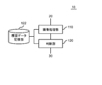
- FIG. 4 is a diagram showing an example of the functional configuration of the station monitoring device 10.
- the station monitoring device 10 includes an image processing unit 110 and a determination unit 120.
- the image processing unit 110 identifies the position of the door 50 of the vehicle 40 and the position of a person by analyzing the image generated by the image pickup apparatus 20, that is, the image of the platform of the station. After the vehicle 40 starts to move, the determination unit 120 determines whether or not to perform a predetermined process by using the position of the door 50 and the position of the person.
- the determination unit 120 uses the data stored in the history data storage unit 122.
- the history data storage unit 122 stores at least one of the history data of the position of the person and the position of the door specified by the image processing unit 110 and the history data of the relative position of the position of the person and the position of the door. Then, the determination unit 120 determines whether or not to perform a predetermined process using the history data. Details of the processing performed by the image processing unit 110 and the processing performed by the determination unit 120 will be described with reference to other figures.
- the history data storage unit 122 may be a part of the station monitoring device 10 or may be located outside the station monitoring device 10.
- FIG. 5A shows a first example of processing in which the image processing unit 110 detects the position of a person on the platform.
- the image processing unit 110 detects a region in which a person exists, for example, by performing feature quantity matching. Then, the image processing unit 110 sets the center of the detected area as the position of the person. In the example shown in this figure, the area where a person exists is indicated by a rectangle. Then, the image processing unit 110 sets the center of the rectangle, that is, the intersection of the two diagonal lines, as the position of the person.
- FIG. 5B shows a second example of processing in which the image processing unit 110 detects the position of a person on the platform.
- the image processing unit 110 estimates the human skeleton and further estimates the position of the joint. Then, the image processing unit 110 sets the position of the joint closest to the door 50 (for example, the end portion 52 or the end portion 54 described later), that is, the position of the joint closest to the door 50, as the position of the person among the estimated joint positions.
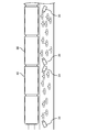
- FIG. 6A shows a first example of processing in which the image processing unit 110 detects the position of the door 50 of the vehicle 40.
- the image processing unit 110 detects the end portion 52 of the door 50, for example, by performing feature quantity matching. Then, the detected end portion 52 is set as the position of the door.
- the door 50 has four ends, but the image processing unit 110 preferably uses the upper end 52 of the door 50 as the position of the door. In this way, the image processing unit 110 can detect the position of the door 50 even if the lower part of the door 50 is hidden by, for example, a platform door.
- FIG. 6B shows a second example of processing in which the image processing unit 110 detects the position of the door 50 of the vehicle 40.
- the door 50 of the vehicle 40 is often a double door.
- the image processing unit 110 detects the end portion 54 of the portion where the two doors constituting the door 50 are in contact with each other (hereinafter, referred to as a tangent line) by performing feature quantity matching, for example. Then, the detected end portion 54 is set as the position of the door. Also in this example, it is preferable that the image processing unit 110 uses the upper end 54 of the close battle as the position of the door.
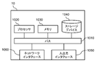
- FIG. 7 is a diagram showing a hardware configuration example of the station monitoring device 10.
- the station monitoring device 10 includes a bus 1010, a processor 1020, a memory 1030, a storage device 1040, an input / output interface 1050, and a network interface 1060.
- the bus 1010 is a data transmission path for the processor 1020, the memory 1030, the storage device 1040, the input / output interface 1050, and the network interface 1060 to transmit and receive data to and from each other.
- the method of connecting the processors 1020 and the like to each other is not limited to the bus connection.
- the processor 1020 is a processor realized by a CPU (Central Processing Unit), a GPU (Graphics Processing Unit), or the like.
- the memory 1030 is a main storage device realized by a RAM (Random Access Memory) or the like.
- the storage device 1040 is an auxiliary storage device realized by an HDD (Hard Disk Drive), an SSD (Solid State Drive), a memory card, a ROM (Read Only Memory), or the like.
- the storage device 1040 stores a program module that realizes each function of the station monitoring device 10 (for example, the image processing unit 110 and the determination unit 120).
- the processor 1020 reads each of these program modules into the memory 1030 and executes them, each function corresponding to the program module is realized.
- the storage device 1040 also functions as a history data storage unit 122.
- the input / output interface 1050 is an interface for connecting the station monitoring device 10 and various input / output devices (for example, the image pickup device 20 and the output device 30).
- the network interface 1060 is an interface for connecting the station monitoring device 10 to the network.
- This network is, for example, LAN (Local Area Network) or WAN (Wide Area Network).
- the method of connecting the network interface 1060 to the network may be a wireless connection or a wired connection.
- the station monitoring device 10 may be connected to at least one of the image pickup device 20 and the output device 30 via the network interface 1060.
- FIG. 8 is a flowchart showing a first example of processing performed by the station monitoring device 10. The process shown in this figure is performed after the vehicle 40 starts to move. The start of movement of the vehicle 40 is detected by, for example, processing an image generated by the image pickup device 20 (for example, detection of a change in the position of the end portion 52), but even if it is detected by using another method. Good.
- any image pickup device 20 When any image pickup device 20 generates an image, the image is transmitted to the station monitoring device 10.
- the station monitoring device 10 acquires an image from the image pickup device 20 together with date and time information indicating the generation date and time of the image (step S10).
- the image processing unit 110 and the determination unit 120 perform the following processing for all the doors 50 of the vehicle 40.
- the image processing unit 110 detects the position of a person and the position of the door 50 included in the image, and stores the detection result in the history data storage unit 122 as data associated with the date and time information, that is, as the above-mentioned history data.
- the determination unit 120 preferably limits the person to be detected to a person who is located within a predetermined distance (for example, within 2 m) from the door 50.
- the determination unit 120 detects the position of the door 50 by first processing the image.
- the determination unit 120 sets an area of the image located within a predetermined distance from the detected door 50 as an area to be detected by a person. By doing so, the processing load of the station monitoring device 10 can be reduced.
- the determination unit 120 calculates the moving speed of the position of the door 50 by using the history data stored in the history data storage unit 122 and the position of the door 50 generated by the image processing unit 110 this time. Further, the determination unit 120 calculates the moving speed of the position of the person by using the history data stored in the history data storage unit 122 and the position of the person generated by the image processing unit 110 this time (step S30).
- the speed of the door 50 and the speed of a person are represented by, for example, the number of moving pixels / frame (or unit time) or the actual moving distance / frame (or unit time). Then, when the difference between the calculated two moving speeds is within the reference (step S40: Yes), the determination unit 120 increases the counter value, that is, the duration by one frame (step S50).
- step S70 When the value of the counter reaches the standard, that is, when the difference between the moving speed of the door 50 and the person is within the standard time continues for the reference time or longer (step S60: Yes), the door 50 is the property of the person or the person. Since there is a high possibility that the door is sandwiched between the two, the determination unit 120 executes a predetermined process (step S70).
- the reference (reference time) in step S60 is, for example, 1/30 second or more. Further, this standard is preferably 1 second or less. Further, the process performed in step S70 is, for example, a process of stopping the vehicle 40 having the door 50. At this time, the determination unit 120 may output a warning sound to the speaker installed at the station.
- the reference time is not a fixed value, but may fluctuate according to the moving distance (number of moving pixels) per unit time. Specifically, the reference time is shortened as the travel distance per unit time increases. For example, when the number of moving pixels of the door 50 between a certain time T and time T + ⁇ exceeds a predetermined number of pixels (for example, 10 pixels or more), the time interval ⁇ is set as the reference time. In other words, the time interval ⁇ required for the number of moving pixels of the door 50 to exceed a predetermined number of pixels is set as the reference time.
- the reference time dynamic in this way, it is possible to lengthen the reference time when the train starts running and shorten the reference time when the train reaches a certain speed. This reduces the risk that the reference time is too short and is affected by minute noise, or the reference time is too long and the judgment becomes excessively slow, and the optimum reference time is set according to the running speed of the train. become able to.
- the determination unit 120 calculates the difference between the two moving speeds as a vector. Then, it is preferable that a component in a specific direction (for example, the moving direction of the vehicle 40) of this vector is used as a judgment target. For example, with respect to the vector representing the difference between the two moving speeds, if the moving direction component of the vehicle 40 is less than the reference, it may be determined that the moving amounts of the person and the train are equivalent. By judging only the moving direction component of the vehicle 40, the influence of noise generated by the movement of a person can be mitigated.
- a component in a specific direction for example, the moving direction of the vehicle 40
- the determination unit 120 indicates information indicating the position of the door 50 (that is, the door 50 determined to have reached the standard in step S60) in which a person or a person's property is likely to be sandwiched (hereinafter, the door position information).
- the description is preferably output to the output device 30.
- the output device 30 is, for example, a mobile terminal owned by a station employee and / or a display device installed at the station. In this way, the station staff can respond quickly.
- the door position information output to the door 50 is generated using, for example, the position of the door 50 detected by the image processing unit 110 (for example, the positions of the ends 52 and 54).
- the door position information output to the output device 30 may include, for example, the position of the image pickup device 20 that generated the image in which the door 50 is captured.
- the image pickup device 20 transmits the identification information of the image pickup device 20 together with the image to the station monitoring device 10. Then, the station monitoring device 10 stores the identification information of the image pickup device 20 in advance in association with the position of the image pickup device 20. Then, the determination unit 120 identifies the position corresponding to the identification information transmitted from the image pickup apparatus 20 by using the stored information.
- step S50 If the difference in moving speed exceeds the reference in step S50, the determination unit 120 resets the counter value (step S52) and returns to step S10.
- FIG. 9 is a flowchart showing a second example of processing performed by the station monitoring device 10.
- the determination unit 120 calculates the moving speed of the door and the moving speed of the person, and uses the difference for the determination (step S30 and step S40). Instead, the following processing is performed.
- step S20 When the image processing unit 110 detects the position of the door and the position of a person (step S20), the determination unit 120 calculates the difference between the two positions. This difference indicates the relative distance between the door and the person (step S32). Then, when the relative position is equal to or less than the reference value (step S42: Yes), the determination unit 120 performs the processes after step S50. If the relative position exceeds the reference value (step S42No), the determination unit 120 resets the counter (step S52) and returns to step S10.
- the station monitoring device 10 identifies the position of the door 50 of the vehicle 40 and the position of a person by analyzing the image of the platform of the station. Then, it is determined whether or not to perform a predetermined process using these positions. For example, even if a person is moving at a speed close to that of the vehicle 40 at a place away from the door 50, the station monitoring device 10 does not determine that the person or his / her belongings are caught in the door 50. Further, even if the person's belongings sandwiched between the doors 50 are thin, that can be detected. Therefore, it is possible to accurately detect that a person or a person's belongings are caught in the door 50.
- Image processing means to identify the position of the vehicle door and the position of a person by analyzing the image taken of the platform of the station, After the vehicle starts to move, a determination means for determining whether or not to perform a predetermined process by using the position of the door and the position of the person, and Station monitoring device equipped with.
- the determination means is a station monitoring device that performs the predetermined processing when it is determined that the difference between the movement speed of any one of the persons and the movement speed of the door is within the reference for a continuous reference time. 3.
- the determination means is a station monitoring device that performs the predetermined process when it is determined that the relative distance between the person and the door is within the reference time continuously for the reference time. 4.
- the position of the door is a station monitoring device at the end of the door. 6.
- the door is a double door, The position of the door is a station monitoring device that is the end of the tangent line of the two doors. 7. In the station monitoring device according to any one of 1 to 6 above.
- the image processing means is a station monitoring device whose position is the center of the area where the person exists. 8. In the station monitoring device according to any one of 1 to 6 above. The image processing means is a station monitoring device that estimates the position of the joint of the person and sets the position closest to the position of the door among the positions of the joint as the position of the person. 9. In the station monitoring device according to any one of 1 to 8 above.
- the predetermined process is a station monitoring device including a process of stopping the vehicle. 10. In the station monitoring device according to any one of 1 to 9 above. The predetermined process is a station monitoring device that includes output of information indicating the position of the door. 11. In the station monitoring device according to the above 10.
- the determination means is a station monitoring device that outputs information indicating the position of the door to a mobile terminal possessed by a station employee. 12.
- the computer By analyzing the images taken of the platform of the station, the position of the vehicle door and the position of the person can be identified.
- the computer is a station monitoring method in which the position of the person is the center of the area where the person exists. 19.
- the predetermined process is a station monitoring method including a process of stopping the vehicle. 21.
- the predetermined process is a station monitoring method including output of information indicating the position of the door. 22.
- the predetermined process is a program including a process of stopping the vehicle.
- the predetermined process is a program including output of information indicating the position of the door.
- Station monitoring device 20 Imaging device 30 Output device 40 Vehicle 50 Door 52 End 54 End 110 Image processing unit 120 Judgment unit 122 History data storage unit
Landscapes
- Engineering & Computer Science (AREA)
- Physics & Mathematics (AREA)
- General Physics & Mathematics (AREA)
- Theoretical Computer Science (AREA)
- Multimedia (AREA)
- Computer Vision & Pattern Recognition (AREA)
- Mechanical Engineering (AREA)
- Train Traffic Observation, Control, And Security (AREA)
- Image Analysis (AREA)
Priority Applications (3)
| Application Number | Priority Date | Filing Date | Title |
|---|---|---|---|
| PCT/JP2020/000684 WO2021140654A1 (ja) | 2020-01-10 | 2020-01-10 | 駅監視装置、駅監視方法、及びプログラム |
| US17/789,985 US12243312B2 (en) | 2020-01-10 | 2020-01-10 | Station monitoring apparatus, station monitoring method, and non-transitory computer readable medium |
| JP2021569697A JPWO2021140654A1 (https=) | 2020-01-10 | 2020-01-10 |
Applications Claiming Priority (1)
| Application Number | Priority Date | Filing Date | Title |
|---|---|---|---|
| PCT/JP2020/000684 WO2021140654A1 (ja) | 2020-01-10 | 2020-01-10 | 駅監視装置、駅監視方法、及びプログラム |
Publications (1)
| Publication Number | Publication Date |
|---|---|
| WO2021140654A1 true WO2021140654A1 (ja) | 2021-07-15 |
Family
ID=76787805
Family Applications (1)
| Application Number | Title | Priority Date | Filing Date |
|---|---|---|---|
| PCT/JP2020/000684 Ceased WO2021140654A1 (ja) | 2020-01-10 | 2020-01-10 | 駅監視装置、駅監視方法、及びプログラム |
Country Status (3)
| Country | Link |
|---|---|
| US (1) | US12243312B2 (https=) |
| JP (1) | JPWO2021140654A1 (https=) |
| WO (1) | WO2021140654A1 (https=) |
Citations (4)
| Publication number | Priority date | Publication date | Assignee | Title |
|---|---|---|---|---|
| JPH10297491A (ja) * | 1997-04-28 | 1998-11-10 | Nippon Denki Ido Tsushin Kk | 列車人身事故防止システム |
| JP2012011988A (ja) * | 2010-07-05 | 2012-01-19 | Saxa Inc | 鉄道車両のドアの紐状異物の検出装置 |
| JP2012035763A (ja) * | 2010-08-06 | 2012-02-23 | Nippon Signal Co Ltd:The | ホームでの旅客引きずり検知システム |
| WO2018179781A1 (ja) * | 2017-03-29 | 2018-10-04 | パナソニックIpマネジメント株式会社 | 車両ドア監視システムおよび車両ドア監視方法 |
Family Cites Families (7)
| Publication number | Priority date | Publication date | Assignee | Title |
|---|---|---|---|---|
| US5387768A (en) * | 1993-09-27 | 1995-02-07 | Otis Elevator Company | Elevator passenger detector and door control system which masks portions of a hall image to determine motion and court passengers |
| US6323762B1 (en) * | 2000-11-16 | 2001-11-27 | Udo U. Ekpo, Jr. | Car jacking prevention system |
| JP5559593B2 (ja) | 2010-05-19 | 2014-07-23 | 株式会社日立国際電気 | 監視システム |
| KR20130026942A (ko) * | 2011-09-06 | 2013-03-14 | 한국전자통신연구원 | 차량의 위험감지장치 및 그 제어방법 |
| JP6503146B2 (ja) * | 2016-09-26 | 2019-04-17 | 株式会社日立国際電気 | 車両監視システム、管理装置、及び監視方法 |
| WO2018180311A1 (ja) * | 2017-03-28 | 2018-10-04 | 株式会社日立国際電気 | 監視システム及び監視方法 |
| JP2022136645A (ja) * | 2021-03-08 | 2022-09-21 | 本田技研工業株式会社 | 車両制御装置、及び車両制御方法 |
-
2020
- 2020-01-10 WO PCT/JP2020/000684 patent/WO2021140654A1/ja not_active Ceased
- 2020-01-10 US US17/789,985 patent/US12243312B2/en active Active
- 2020-01-10 JP JP2021569697A patent/JPWO2021140654A1/ja active Pending
Patent Citations (4)
| Publication number | Priority date | Publication date | Assignee | Title |
|---|---|---|---|---|
| JPH10297491A (ja) * | 1997-04-28 | 1998-11-10 | Nippon Denki Ido Tsushin Kk | 列車人身事故防止システム |
| JP2012011988A (ja) * | 2010-07-05 | 2012-01-19 | Saxa Inc | 鉄道車両のドアの紐状異物の検出装置 |
| JP2012035763A (ja) * | 2010-08-06 | 2012-02-23 | Nippon Signal Co Ltd:The | ホームでの旅客引きずり検知システム |
| WO2018179781A1 (ja) * | 2017-03-29 | 2018-10-04 | パナソニックIpマネジメント株式会社 | 車両ドア監視システムおよび車両ドア監視方法 |
Also Published As
| Publication number | Publication date |
|---|---|
| US20220415053A1 (en) | 2022-12-29 |
| US12243312B2 (en) | 2025-03-04 |
| JPWO2021140654A1 (https=) | 2021-07-15 |
Similar Documents
| Publication | Publication Date | Title |
|---|---|---|
| JP2016179810A (ja) | 自動走行制御装置及び自動走行制御システム | |
| US20260082019A1 (en) | Image processing system, communication apparatus, and image processing method | |
| US11961400B2 (en) | Passenger vehicle and operation management system | |
| US20230133873A1 (en) | Remote monitoring system, remote monitoring apparatus, and method | |
| US20210146946A1 (en) | Information collection device and information collection method | |
| WO2021140654A1 (ja) | 駅監視装置、駅監視方法、及びプログラム | |
| JP7473016B2 (ja) | システム、情報処理装置、方法、及びプログラム | |
| JPH08180276A (ja) | 障害物検知方法及びその装置 | |
| JP7186749B2 (ja) | 管理システム、管理方法、管理装置、プログラム及び通信端末 | |
| WO2022172912A1 (ja) | 情報収集制御装置、情報収集制御方法、情報収集制御プログラム | |
| JP2023044275A (ja) | 救助優先度判定装置 | |
| JP2022096793A (ja) | 車両ドア寄り掛かり検出システム | |
| CN117351774A (zh) | 一种基于自动驾驶车辆的机非碰撞预警系统及方法 | |
| JP7558051B2 (ja) | ホームドアシステム | |
| JP7521619B2 (ja) | 情報処理装置、情報処理方法およびプログラム | |
| JP2007058751A (ja) | 物体判別装置、物体判別方法および物体判別プログラム | |
| JP2020036164A (ja) | 画像処理装置 | |
| JP7524900B2 (ja) | 危険検知システム、方法及びプログラム並びに危険場所検出装置 | |
| JP2022175943A (ja) | 情報提示装置 | |
| JP7550047B2 (ja) | 情報処理装置 | |
| JP7757467B1 (ja) | エレベータシステム | |
| WO2024121963A1 (ja) | 情報処理装置、情報処理システム、情報処理方法、及び非一時的なコンピュータ可読媒体 | |
| JP7544580B2 (ja) | 旅客接近検知システム及び旅客接近検知方法 | |
| CN119116836B (zh) | 车辆开门预警方法、装置、计算机设备及存储介质 | |
| KR20250140901A (ko) | 능동소음제어 센서 위치 선정 장치 및 방법 |
Legal Events
| Date | Code | Title | Description |
|---|---|---|---|
| 121 | Ep: the epo has been informed by wipo that ep was designated in this application |
Ref document number: 20912142 Country of ref document: EP Kind code of ref document: A1 |
|
| ENP | Entry into the national phase |
Ref document number: 2021569697 Country of ref document: JP Kind code of ref document: A |
|
| NENP | Non-entry into the national phase |
Ref country code: DE |
|
| 122 | Ep: pct application non-entry in european phase |
Ref document number: 20912142 Country of ref document: EP Kind code of ref document: A1 |
|
| WWG | Wipo information: grant in national office |
Ref document number: 17789985 Country of ref document: US |