WO2021136952A1 - 電動モータユニット - Google Patents
電動モータユニット Download PDFInfo
- Publication number
- WO2021136952A1 WO2021136952A1 PCT/IB2019/001415 IB2019001415W WO2021136952A1 WO 2021136952 A1 WO2021136952 A1 WO 2021136952A1 IB 2019001415 W IB2019001415 W IB 2019001415W WO 2021136952 A1 WO2021136952 A1 WO 2021136952A1
- Authority
- WO
- WIPO (PCT)
- Prior art keywords
- case
- wall surface
- stator
- electric motor
- motor unit
- Prior art date
- Legal status (The legal status is an assumption and is not a legal conclusion. Google has not performed a legal analysis and makes no representation as to the accuracy of the status listed.)
- Ceased
Links
Images


Classifications
-
- H—ELECTRICITY
- H02—GENERATION; CONVERSION OR DISTRIBUTION OF ELECTRIC POWER
- H02K—DYNAMO-ELECTRIC MACHINES
- H02K9/00—Arrangements for cooling or ventilating
- H02K9/19—Arrangements for cooling or ventilating for machines with closed casing and closed-circuit cooling using a liquid cooling medium, e.g. oil
-
- H—ELECTRICITY
- H02—GENERATION; CONVERSION OR DISTRIBUTION OF ELECTRIC POWER
- H02K—DYNAMO-ELECTRIC MACHINES
- H02K2205/00—Specific aspects not provided for in the other groups of this subclass relating to casings, enclosures, supports
- H02K2205/09—Machines characterised by drain passages or by venting, breathing or pressure compensating means
-
- Y—GENERAL TAGGING OF NEW TECHNOLOGICAL DEVELOPMENTS; GENERAL TAGGING OF CROSS-SECTIONAL TECHNOLOGIES SPANNING OVER SEVERAL SECTIONS OF THE IPC; TECHNICAL SUBJECTS COVERED BY FORMER USPC CROSS-REFERENCE ART COLLECTIONS [XRACs] AND DIGESTS
- Y02—TECHNOLOGIES OR APPLICATIONS FOR MITIGATION OR ADAPTATION AGAINST CLIMATE CHANGE
- Y02T—CLIMATE CHANGE MITIGATION TECHNOLOGIES RELATED TO TRANSPORTATION
- Y02T10/00—Road transport of goods or passengers
- Y02T10/60—Other road transportation technologies with climate change mitigation effect
- Y02T10/64—Electric machine technologies in electromobility
Definitions
- the present invention relates to an electric motor unit.
- a waterproof box-shaped case used for equipment such as an electric motor and a transmission is provided with a respiratory membrane made of a synthetic resin such as PTFE in order to alleviate a pressure difference between the inside and outside of the case. ing. It is also known that a coolant is used to cool the parts housed in the case.
- JP2017-125536A discloses a configuration in which the opening of the passage communicating with the respiratory membrane is covered with a cover formed of a member different from the case in order to prevent the coolant from adhering to the respiratory membrane.
- an object of the present invention is to suppress the impregnation of the respiratory membrane with the coolant without causing each of the above problems.
- An electric motor unit includes a case, a stator housed in the case, a rotor rotatably held inside the stator, and a rotating shaft provided on the rotor and rotatably supported by the case.
- a cooling device that injects coolant toward the stator, and a ventilation path that has a breathing membrane that allows the passage of air and penetrates from the inner wall surface to the outer wall surface of the case, and further, an injection port of the cooling device. It is provided with a predetermined electrical component arranged between the air passage and the opening on the inner wall surface side of the ventilation path.
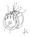
- FIG. 1 is an exploded perspective view of the electric motor unit according to the first embodiment.
- FIG. 2 is a diagram for explaining the flow of the coolant.
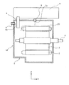
- FIG. 3 is a cross-sectional view of the electric motor unit according to the first embodiment as viewed from the horizontal direction.
- FIG. 4 is a view of the electric motor unit according to the first embodiment as viewed from the direction of the rotation axis.
- FIG. 5 is a view of the bus bar unit as viewed from the stator side.
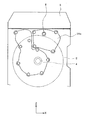
- FIG. 6 is a view of the electric motor unit according to the first embodiment as viewed from the direction of the rotation axis.
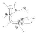
- FIG. 7 is a diagram for explaining the configuration of the ventilation path outside the case.
- FIG. 8 is a cross-sectional view of the electric motor unit according to the second embodiment as viewed from the horizontal direction.
- FIG. 1 is an exploded perspective view of the electric motor unit 10 according to the present embodiment.
- the electric motor unit 10 is used as a power source for, for example, an electric vehicle or a hybrid vehicle.
- the Z-axis direction in FIG. 1 is the upward direction in the used state.
- the direction along the X-axis is the left-right direction or the horizontal direction
- the direction along the Y-axis is the front-back direction or the axial direction
- the direction along the Z-axis is the up-down direction.
- the electric motor unit 10 includes a stator 2, a case 1 accommodating the stator 2, a rotating shaft 4 rotatably supported by the case 1, and a rotor 3 fixedly supported by the rotating shaft 4.
- a cooling device 5 for injecting a cooling liquid toward the stator 2 and a ventilation path 6 for adjusting the pressure in the case 1 are provided.
- the wall surface 1A provided with the ventilation passage 6 is shown by disassembling one wall surface in the axial direction of the case 1 for the sake of explanation.
- the bus bar group 9 shown between the wall surface 1A and the stator 2 is an electric wiring for supplying electric power to the stator 2 from an inverter (not shown). Details of the bus bar group 9 will be described later with reference to FIGS. 3 to 5.
- the bus bar group 9 in the electric motor unit 10 in the undisassembled state is configured to penetrate from the outside to the inside of the case 1, but the through hole through which the bus bar group 9 penetrates in the case 1 is omitted in FIG. Has been done.
- the stator 2 is composed of a stator core 2A made of laminated steel plates, a coil (not shown) arranged in a slot of the stator core 2A, and a stator holder 2B that holds the stator core 2A from the outer peripheral side.
- the stator core 2A, the coil, and the stator holder 2B are collectively referred to as the stator 2 unless it is necessary to distinguish them.
- the stator holder 2B includes a plurality of bolt holes 7, and the stator 2 is fixed to the case 1 through a plurality of bolt holes 7 by bolts (not shown).
- a protrusion 2C that protrudes in the radial direction of the stator holder 2B and extends from the front end to the rear end of the stator holder 2B is provided on the outer periphery of the stator holder 2B of the present embodiment, but the protrusion 2C is not necessarily provided. No need.
- the outer circumference of the stator holder 2B is not limited to the shape shown in the figure, and may be, for example, a cylindrical shape similar to the outer circumference of the stator 2.
- the case 1 is formed in a box shape having a space for accommodating an electric motor composed of a stator 2, a rotor 3, and a rotating shaft 4.
- the case 1 is provided with a cooling device 5 and a ventilation passage 6, which will be described later.
- a coolant reservoir 1B is provided in the lower part of the case 1.
- the coolant reservoir 1B may be formed integrally with the case 1, or a member formed as a separate member may be attached to the case 1.
- the type of coolant used is not particularly limited, but the coolant used in this embodiment is oil.
- the rotating shaft 4 is rotatably supported by the case 1 via a bearing (not shown).
- the rotor 3 is fixedly supported on the rotating shaft 4 by a method such as press fitting, and rotates integrally with the rotating shaft 4.
- the cooling device 5 is a device for cooling mainly the coil end portion of the stator 2 housed in the case 1.
- the cooling device 5 of the present embodiment is arranged so that the injection port 5a faces the inside of the case at substantially the center in the left-right direction and substantially the center in the front-rear direction on the upper surface of the case 1, and the cooling liquid is vertically downward from the injection port 5a.
- the position of the upper surface of the case 1 at a substantially center in the left-right direction and a substantially center in the front-rear direction is referred to as a "vertex".
- the coolant is assembled from the coolant reservoir 1B by an oil pump (not shown) and sent to the cooling device 5 via the coolant passage (not shown).
- the flow of the coolant supplied from the injection port 5a will be described later.
- the ventilation passage 6 is a ventilation pipe that penetrates from the inner wall surface to the outer wall surface of the case 1.
- the ventilation passage 6 has a function of alleviating the pressure difference between the inside and outside of the case 1.
- the air passage 6 is provided with a respiratory membrane having a function of allowing air to pass through but not allowing dust and liquid to pass through, and does not allow a passage that communicates inside and outside the case 1 when connected to the air passage 6. It is configured as a pressure regulator configured to close with the illustrated respiratory membrane.
- the respiratory membrane is a thin film formed of a synthetic resin (for example, Poly Terra Fluoro Ethylene: PTFE). Details regarding the arrangement of the respiratory membrane and the like will be described later with reference to FIG.
- the case 1 is provided so that a predetermined electric component is interposed between the opening on the inner wall surface side (hereinafter, this opening is referred to as the inner wall surface side opening 6a) and the injection port 5a.
- the predetermined electrical component here is not particularly limited, but may be an electrical wiring, a connector, or the like for supplying electric power to the stator 2.
- the electric component not only the electric component itself having conductivity such as electric wiring, but also a cover member such as resin covering the electric component, a case for accommodating the electric component, or an electric wiring is arranged. It shall also include a clamp member for the purpose.
- the bus bar group 9 is configured as a predetermined electric component.
- the bus bar group 9 collectively refers to flat plate-shaped bus bars 9u, 9v, 9w for supplying electricity to the stator coils of each phase (for example, U phase, V phase, and W phase) provided in the stator 2. ..
- the bus bars 9u, 9v, and 9w are arranged side by side in the horizontal direction with the plane directions orthogonal to the axial direction.
- the bus bar group 9 of the present embodiment is configured as a bus bar unit 9 in which the bus bars 9u, 9v, and 9w are covered with a resin in order to ensure the insulating property between the electrodes.
- the bus bar group 9 is arranged in the horizontal direction so that the bus bars 9u, 9v, and 9w do not overlap each other when viewed from the axial direction.
- the width of the bus bar group 9 in the horizontal direction becomes wider, so that the function as a barrier against the coolant described later can be enhanced.
- the bus bars 9u, 9v, and 9w may have portions that overlap each other when viewed from the axial direction.
- the bus bars 9u, 9v, and 9w do not necessarily have to be arranged at positions that coincide with each other in the axial direction as shown in the drawing, and may be arranged so as to be offset from each other in the axial direction. The details of the bus bar group 9 and the positional relationship between the bus bar group 9 and the inner wall surface side opening 6a will be described later with reference to FIGS. 3 to 5.
- FIG. 2 is a perspective view of the stator 2, the rotor 3, and the rotating shaft 4.
- the thick arrow in the figure indicates the flow of the coolant.
- P in the figure indicates a portion of the upper surface 2D of the stator 2 that receives the above-mentioned coolant.
- the coolant is injected toward the stator 2 from the injection port 5a of the cooling device 5 arranged at the apex of the case 1 and collides with the portion P that receives the coolant of the stator 2.
- the coolant that collides with the portion P flows radially dispersedly on the outer peripheral surface of the stator 2, and a part of the coolant reaches each end of the stator 2 in the front-rear direction as it is, and the coil end that becomes hot when operated is provided. Cooling.
- the coolant that collides with the protrusion 2C before reaching each end of the stator 2 in the left-right direction is a pool defined by the wall surface of the protrusion 2C on the P side and the upper surface of the stator 2. Accumulate in the club. Since the end portion of the stator 2 in the front-rear direction is open in the pool portion shown by the broken line in FIG. 3, the coolant collected in the pool portion flows along the protrusion 2C in the front-rear direction of the stator 2 to cool the coil end. To do.
- the coolant that cooled the coil end is collected in the coolant reservoir 1B (see FIG. 1) below the case 1.
- the coolant injected from the injection port 5a may collide with the stator 2 to form droplets and enter the ventilation passage 6. Then, when the cooling liquid enters the ventilation passage 6 repeatedly, the cooling liquid is accumulated in the ventilation passage 6, and the respiratory membrane is impregnated with the cooling liquid, so that the air permeability of the respiratory membrane is lowered, and the air permeability is adjusted by the ventilation passage 6. There is a problem that the pressure function is reduced.
- the above problem is caused by interposing an electric component (bus bar group 9) between the injection port 5a of the cooling device 5 and the opening 6a on the inner wall surface side of the ventilation path 6.
- bus bar group 9 an electric component
- FIGS. 3 and 4 the positional relationship between the bus bar group 9 and the inner wall surface side opening 6a of the present embodiment will be described with reference to FIGS. 3 and 4.
- FIG. 3 is a cross-sectional view of the electric motor unit 10 of the present embodiment shown in FIG. 1 as viewed from the horizontal direction (X-axis direction of FIG. 1).
- the positional relationship between the bus bar group 9, the inner wall surface side opening 6a, and the injection port 5a in the axial direction will be described with reference to FIG.
- the dotted arrow shown in the figure indicates a part of the flow (oil passage) of the coolant injected into the case 1.
- the inverter case 8 shown in the figure is a case for accommodating the inverter inside, and is arranged above the case 1.
- the bus bar group 9 is configured to project from the inverter case 8 to the inside of the case 1, and is connected to the coil provided in the stator 2 in each phase inside the case 1 to electrically connect the inverter and the coil. To supply electricity to the stator 2.
- the illustration of the connection portion between the bus bar group 9 and the coil is omitted.
- the injection port 5a is arranged so as to inject the coolant from the upper side of the case 1 toward the inside of the case 1 on the upper surface of the case 1.
- the inner wall surface side opening 6a of the ventilation path 6 is arranged on the axial end surface (wall surface 1A) on the front side of the case 1.
- the bus bar group 9 is arranged inside the case 1 between the injection port 5a and the inner wall surface side opening 6a.
- the bus bar group 9 by interposing the bus bar group 9 between the inner wall surface side opening 6a of the ventilation path 6 and the injection port 5a, the bus bar group 9 with respect to the flow of the coolant. Acts as a barrier. As a result, the ingress of the coolant into the ventilation passage 6 is suppressed, and as a result, the impregnation of the respiratory membrane with the coolant can be suppressed.
- the position of the inner wall surface side opening 6a of the ventilation path 6 in the vertical direction is higher than the upper surface 2D of the stator 2.
- FIG. 4 is a schematic configuration diagram of the electric motor unit 10 of the present embodiment viewed from the axial direction (Y-axis direction of FIG. 1), and is a positional relationship between the inner wall surface side opening 6A and the bus bar group 9 in the left-right direction. It is a figure explaining.
- the inner wall surface side opening 6a is configured to be located at the center of the bus bar group 9 in the left-right direction when viewed from the axial direction.
- the center here includes the meaning of a substantially center that allows a slight bias to the left and right.
- the position of the inner wall surface side opening 6a does not necessarily have to be positioned at the center, and the coolant wraps around the bus bar group 9 from the left and right directions according to the flow path of the cooling water to the inner wall surface side opening 6a. It may be appropriately moved to a position where it can be less likely to be reached.
- FIG. 5 is a schematic configuration diagram of the bus bar group 9 (bus bar unit 9) arranged in the case 1 as viewed from the stator 2 side.
- the bus bar unit 9 is configured such that the bus bars 9u, 9v, 9w are covered with resin.
- the bus bars 9u, 9v, 9w may be configured so that at least a part of the surface on the stator 2 side, that is, the surface facing the flow of the coolant is exposed. As a result, the coolant comes into contact with the exposed surfaces of the bus bars 9u, 9v, 9w, so that the coolant cools the bus bars 9u, 9v, 9w, and the heat generation of the bus bars 9u, 9v, 9w can be suppressed.
- the axial wall surface 1A of the case 1 does not necessarily have to be composed of one member, and may be a structure composed of a plurality of members.
- the wall surface 1A of the case 1 may have a cover member 1Aa as illustrated in FIG.
- FIG. 6 is a diagram illustrating the position of the ventilation path 6 when the axial wall surface 1A of the case 1 is composed of a plurality of members.
- the cover member 1Aa is formed in an arbitrary shape, and is configured to be removable from the wall surface 1A via a bolt or the like.
- a portion of the wall surface 1A corresponding to the shape of the cover member 1Aa is opened.
- the arrangement, shape, and number of cover members provided on the wall surface 1A include a portion where the inner wall surface side opening 6a of the ventilation passage 6 provided in at least one cover member overlaps with the bus bar group 9 when viewed from the axial direction. It suffices if it is done, and there is no particular limitation.
- FIG. 7 is a diagram illustrating a configuration example of the ventilation path 6 outside the case 1.
- the ventilation passage 6 outside the case 1 of the present embodiment includes a ventilation pipe 6b, a hose 6c, an adapter 6d, and a filter 6e.
- the ventilation pipe 6b and the hose 6c are pipes configured to extend the ventilation passage 6 outside the case 1, and the tip on the opposite side connected to the ventilation passage 6 is in the vertical direction of the ventilation passage 6. It is fixed to the wall surface 1A via a predetermined clamp member or the like so as to be located above the position.
- the ventilation pipe 6b is made of metal and the hose 6c is made of a material such as rubber, but these materials may be appropriately selected in consideration of durability, cost and the like.
- the ventilation pipe 6b and the hose 6c do not necessarily have to be formed separately, and may be integrally formed.
- the hose 6c does not necessarily have to have a crank shape as shown in the drawing, and may have a linear shape upward from the position of the ventilation passage 6.
- the filter 6e is a PTFE (respiratory membrane) covered with a general-purpose cover.
- the filter 6e of the present embodiment is connected to the tip of the rubber hose 6c via a flange-shaped adapter 6d.
- the flange-shaped portion of the adapter 6d by arranging the flange-shaped portion of the adapter 6d so as to spread horizontally near the lower portion of the filter 6e, the flange-shaped portion serves as a barrier even when rainwater or the like from the road surface splashes up, for example. Therefore, it is possible to prevent the filter 6e from being exposed to water.
- the pressure regulating device is configured by the ventilation passage 6, the inner wall surface side opening 6a, the ventilation pipe 6b, the hose 6c, the adapter 6d, and the filter 6e.
- the pressure regulating device does not necessarily have to have the configuration shown in FIG. 7, and includes at least a ventilation passage 6 and an inner wall surface side opening 6a, and has a function of alleviating the pressure difference between the inside and outside of the case 1.
- the pressure regulating device may be configured so that the filter 6e is directly connected to the air passage 6 without the hose 6c or the like outside the case 1.
- PTFE it is not always necessary to use PTFE, and instead of the filter 6e, for example, a simple cap may be attached to the tip of the hose 6c.
- the electric motor unit 10 of the present embodiment is provided in the case 1, the stator 2 housed in the case 1, the rotor 3 rotatably held inside the stator 2, and the rotor 3 and rotates in the case.
- a rotating shaft 4 that is freely supported, a cooling device 5 that injects a cooling liquid toward the stator 2, and a ventilation path 6 that has a breathing membrane that allows the passage of air and penetrates from the inner wall surface to the outer wall surface of the case.
- a predetermined electrical component is provided between the injection port of the cooling device and the opening 6a on the inner wall surface side of the ventilation path.
- the electrical components interposed between the inner wall surface side opening 6a of the ventilation passage 6 and the injection port 5a suppress the ingress of the coolant into the ventilation passage 6 to cool the respiratory membrane provided in the ventilation passage 6. Impregnation of liquid can be suppressed. Further, since the electric parts originally provided in the case 1 are used, the number of parts does not increase and the cost does not increase.
- the injection port 5a is arranged at a position that is the upper surface in the used state of the case 1, and the inner wall surface side opening 6a is arranged on the wall surface 1A orthogonal to the rotation axis 4 in the used state of the case 1. Will be done.
- the coil end of the stator 2 can be cooled by utilizing the flow generated by the weight of the coolant.
- the inner wall surface side opening 6a is arranged on the wall surface 1A orthogonal to the rotation axis 4 of the case 1, it is necessary to make a large layout change between the inner wall surface side opening 6a and the injection port 5a. Electrical components can be placed without.
- the inner wall surface side opening 6a is arranged at a position higher than the upper surface 2D of the stator 2 in the vertical direction in the used state of the case 1. As a result, the possibility that the cooling liquid flowing through the stator 2 enters the ventilation passage 6 can be further reduced.
- the inner wall surface side opening 6a is arranged at a position facing the central portion in the horizontal direction of the predetermined electric component (bus bar group 9). As a result, the possibility that the coolant wraps around the bus bar group 9 from the left-right direction and reaches the inner wall surface side opening 6a can be further reduced.
- the predetermined electric component is a bus bar (bus bar group 9) for supplying electric power to the stator.
- the bus bar group 9 is configured as a bus bar unit 9 accommodating a plurality of bus bars corresponding to the number of phases of the stator 2, and the bus bar unit 9 is at least a part of the surface of the bus bar (9u, 9v, 9w) on the stator side. Is configured to be exposed. As a result, the coolant comes into contact with the exposed surfaces of the bus bars 9u, 9v, 9w, so that the coolant cools the bus bars 9u, 9v, 9w, and the heat generation of the bus bars 9u, 9v, 9w can be suppressed.
- FIG. 8 is a cross-sectional view of the electric motor unit 20 according to the second embodiment as viewed from the X-axis direction of FIG.
- the difference from the electric motor unit 10 according to the first embodiment shown in FIG. 3 is that the injection port 5a of the first embodiment is arranged on the upper surface of the case 1, whereas the injection port of the present embodiment is different.
- Reference numeral 5a is that it is arranged on the axial end face of the case 1.
- the injection port 5a of the present embodiment is arranged on the axial end surface of the case 1, and directs the coolant toward any one or more of the stator 2, the rotor 3, and the rotating shaft 4. Is configured to inject.
- the portion where the injected coolant collides with the stator 2, the rotor 3, and the rotating shaft 4 is exemplified as the portions P1, P2, and P3 (see the dotted elliptical frame).
- the bus bar group 9 of the present embodiment is arranged between any one or more of the portions P1, P2, and P3 and the inner wall surface side opening 6a.
- the bus bar group 9 functions as a barrier to the flow of the coolant, and the intrusion of the coolant into the ventilation passage 6 can be suppressed. As a result, it is possible to prevent the respiratory membrane from being impregnated with the coolant.
- the inner wall surface side opening 6a of the present embodiment is arranged at a position higher than the injection port 5a on the wall surface 1A of the case 1. As a result, the possibility that the coolant injected from the injection port 5a enters the inner wall surface side opening 6a can be further reduced.
- the case 1, the stator 2 housed in the case 1, the rotor 3 rotatably held inside the stator 2, and the rotor 3 are provided with the case.
- a ventilation path that has a rotating shaft 4 that is rotatably supported, a cooling device 5 that injects cooling liquid toward the stator 2, and a breathing membrane that allows the passage of air, and penetrates from the inner wall surface to the outer wall surface of the case. 6 and a predetermined electric motor provided between the positions (sites P1, P2, P3) where the cooling liquid jetted from the cooling device 5 collides with each other and the inner wall surface side opening 6a of the ventilation passage 6. Equipped with parts.
- the electrical components interposed between the inner wall surface side opening 6a of the ventilation passage 6 and the positions where the coolant collides suppress the entry of the coolant into the ventilation passage 6.
- the impregnation of the cooling liquid into the respiratory membrane provided in the ventilation passage 6 can be suppressed.
- the inner wall surface side opening 6a is arranged above the injection port 5a. As a result, the possibility that the coolant injected from the injection port 5a enters the inner wall surface side opening 6a can be further reduced.
- the layout shown in the drawings and the like is an example and is not limited to the illustrated one. Electricity is generated between the injection port 5a and the inner wall surface side opening 6a, or between any of the portions P1, P2, and P3 where the coolant injected from the injection port 5a collides with the motor and the inner wall surface side opening 6a. It may be changed as appropriate on the assumption that parts are involved.
- the inner wall surface side opening 6a may be arranged on the wall surface in the left-right direction of the case 1 in consideration of the positional relationship between the case 1 and the inverter case 8.
Landscapes
- Engineering & Computer Science (AREA)
- Power Engineering (AREA)
- Motor Or Generator Cooling System (AREA)
- Motor Or Generator Frames (AREA)
Priority Applications (5)
| Application Number | Priority Date | Filing Date | Title |
|---|---|---|---|
| EP19958210.7A EP4087100B1 (en) | 2019-12-30 | 2019-12-30 | Electric motor unit |
| JP2021568445A JP7386262B2 (ja) | 2019-12-30 | 2019-12-30 | 電動モータユニット |
| PCT/IB2019/001415 WO2021136952A1 (ja) | 2019-12-30 | 2019-12-30 | 電動モータユニット |
| CN201980103332.3A CN114902539A (zh) | 2019-12-30 | 2019-12-30 | 电动机单元 |
| US17/790,073 US12101016B2 (en) | 2019-12-30 | 2019-12-30 | Electric motor unit |
Applications Claiming Priority (1)
| Application Number | Priority Date | Filing Date | Title |
|---|---|---|---|
| PCT/IB2019/001415 WO2021136952A1 (ja) | 2019-12-30 | 2019-12-30 | 電動モータユニット |
Publications (1)
| Publication Number | Publication Date |
|---|---|
| WO2021136952A1 true WO2021136952A1 (ja) | 2021-07-08 |
Family
ID=76685881
Family Applications (1)
| Application Number | Title | Priority Date | Filing Date |
|---|---|---|---|
| PCT/IB2019/001415 Ceased WO2021136952A1 (ja) | 2019-12-30 | 2019-12-30 | 電動モータユニット |
Country Status (5)
| Country | Link |
|---|---|
| US (1) | US12101016B2 (https=) |
| EP (1) | EP4087100B1 (https=) |
| JP (1) | JP7386262B2 (https=) |
| CN (1) | CN114902539A (https=) |
| WO (1) | WO2021136952A1 (https=) |
Cited By (3)
| Publication number | Priority date | Publication date | Assignee | Title |
|---|---|---|---|---|
| CN114567103A (zh) * | 2022-03-25 | 2022-05-31 | 浙江浙水工贸有限公司 | 一种屏蔽永磁同步电机直连水车式增氧系统 |
| US20220247265A1 (en) * | 2021-01-29 | 2022-08-04 | Hyundai Mobis Co., Ltd. | Terminal block for motor |
| TWI857512B (zh) * | 2023-03-07 | 2024-10-01 | 台達電子工業股份有限公司 | 逆變器以及具有此逆變器的電動馬達 |
Families Citing this family (3)
| Publication number | Priority date | Publication date | Assignee | Title |
|---|---|---|---|---|
| DE102021119486A1 (de) * | 2021-07-27 | 2023-02-02 | Dr. Ing. H.C. F. Porsche Aktiengesellschaft | Elektrische Maschine |
| CN114865844A (zh) * | 2022-06-16 | 2022-08-05 | 华北水利水电大学 | 一种冷却永磁电机 |
| GB2636126A (en) * | 2023-11-29 | 2025-06-11 | Jaguar Land Rover Ltd | Electric drive unit assembly |
Citations (3)
| Publication number | Priority date | Publication date | Assignee | Title |
|---|---|---|---|---|
| JPS57186660U (https=) * | 1981-05-25 | 1982-11-26 | ||
| JP2007116807A (ja) * | 2005-10-19 | 2007-05-10 | Komatsu Ltd | 立型モータ/ジェネレータ |
| JP2017125536A (ja) | 2016-01-13 | 2017-07-20 | Ntn株式会社 | 車両駆動装置 |
Family Cites Families (11)
| Publication number | Priority date | Publication date | Assignee | Title |
|---|---|---|---|---|
| JP5167868B2 (ja) * | 2008-03-03 | 2013-03-21 | 日産自動車株式会社 | 電動機 |
| JP5204015B2 (ja) * | 2009-03-16 | 2013-06-05 | 株式会社東芝 | 回転電機 |
| JP2012120384A (ja) * | 2010-12-03 | 2012-06-21 | Hitachi Automotive Systems Ltd | 駆動装置 |
| JP5738007B2 (ja) * | 2011-03-02 | 2015-06-17 | 株式会社小松製作所 | 電動機の冷却構造及び電動機 |
| JP5978954B2 (ja) * | 2012-11-26 | 2016-08-24 | 三菱自動車工業株式会社 | 回転電機装置 |
| JP6070311B2 (ja) * | 2013-03-18 | 2017-02-01 | 株式会社ジェイテクト | 電動オイルポンプ装置 |
| JP6105387B2 (ja) * | 2013-05-22 | 2017-03-29 | 株式会社日本自動車部品総合研究所 | 回転電機 |
| JP5920308B2 (ja) * | 2013-10-18 | 2016-05-18 | 株式会社デンソー | 回転電機 |
| JP2015130719A (ja) * | 2014-01-06 | 2015-07-16 | トヨタ自動車株式会社 | モータの冷却構造 |
| FR3018645B1 (fr) * | 2014-03-12 | 2016-04-29 | Moteurs Leroy-Somer | Moteur electrique a refroidissement combine liquide et air |
| JP6968272B2 (ja) * | 2018-05-22 | 2021-11-17 | 三菱電機株式会社 | 電動パワーステアリング装置 |
-
2019
- 2019-12-30 EP EP19958210.7A patent/EP4087100B1/en active Active
- 2019-12-30 US US17/790,073 patent/US12101016B2/en active Active
- 2019-12-30 WO PCT/IB2019/001415 patent/WO2021136952A1/ja not_active Ceased
- 2019-12-30 JP JP2021568445A patent/JP7386262B2/ja active Active
- 2019-12-30 CN CN201980103332.3A patent/CN114902539A/zh active Pending
Patent Citations (3)
| Publication number | Priority date | Publication date | Assignee | Title |
|---|---|---|---|---|
| JPS57186660U (https=) * | 1981-05-25 | 1982-11-26 | ||
| JP2007116807A (ja) * | 2005-10-19 | 2007-05-10 | Komatsu Ltd | 立型モータ/ジェネレータ |
| JP2017125536A (ja) | 2016-01-13 | 2017-07-20 | Ntn株式会社 | 車両駆動装置 |
Non-Patent Citations (1)
| Title |
|---|
| See also references of EP4087100A4 |
Cited By (5)
| Publication number | Priority date | Publication date | Assignee | Title |
|---|---|---|---|---|
| US20220247265A1 (en) * | 2021-01-29 | 2022-08-04 | Hyundai Mobis Co., Ltd. | Terminal block for motor |
| US12027948B2 (en) * | 2021-01-29 | 2024-07-02 | Hyundai Mobis Co., Ltd. | Terminal block for motor |
| CN114567103A (zh) * | 2022-03-25 | 2022-05-31 | 浙江浙水工贸有限公司 | 一种屏蔽永磁同步电机直连水车式增氧系统 |
| CN114567103B (zh) * | 2022-03-25 | 2022-11-18 | 浙江浙水工贸有限公司 | 一种屏蔽永磁同步电机直连水车式增氧系统 |
| TWI857512B (zh) * | 2023-03-07 | 2024-10-01 | 台達電子工業股份有限公司 | 逆變器以及具有此逆變器的電動馬達 |
Also Published As
| Publication number | Publication date |
|---|---|
| US12101016B2 (en) | 2024-09-24 |
| EP4087100A4 (en) | 2022-12-28 |
| JPWO2021136952A1 (https=) | 2021-07-08 |
| US20230058881A1 (en) | 2023-02-23 |
| CN114902539A (zh) | 2022-08-12 |
| EP4087100B1 (en) | 2026-04-22 |
| JP7386262B2 (ja) | 2023-11-24 |
| EP4087100A1 (en) | 2022-11-09 |
Similar Documents
| Publication | Publication Date | Title |
|---|---|---|
| WO2021136952A1 (ja) | 電動モータユニット | |
| JP7439820B2 (ja) | モータユニット | |
| KR101464558B1 (ko) | 발전 전동기 및 작업 기계 | |
| KR101464557B1 (ko) | 발전 전동기 및 작업 기계 | |
| KR101464555B1 (ko) | 발전 전동기 및 작업 기계 | |
| CN103107629B (zh) | 旋转电机 | |
| CN204013085U (zh) | 旋转电机、旋转电机用框架和车辆 | |
| JP5421225B2 (ja) | 作業機械、電気制御ユニット、およびインバータ | |
| JP5978954B2 (ja) | 回転電機装置 | |
| JP6787677B2 (ja) | 電動パワーユニット | |
| CN116073589A (zh) | 驱动装置 | |
| US11095183B2 (en) | Electric pump device | |
| JP7647181B2 (ja) | 回転電機、および駆動装置 | |
| JP2023098234A (ja) | 電動作業機 | |
| US10033241B2 (en) | Generator motor | |
| WO2020109832A1 (ja) | 電動モータユニッ卜 | |
| US20250132629A1 (en) | Rotating Electric Machine | |
| JP2025058444A (ja) | 回転電機、および駆動装置 | |
| KR20260051958A (ko) | 작업 기계 |
Legal Events
| Date | Code | Title | Description |
|---|---|---|---|
| 121 | Ep: the epo has been informed by wipo that ep was designated in this application |
Ref document number: 19958210 Country of ref document: EP Kind code of ref document: A1 |
|
| ENP | Entry into the national phase |
Ref document number: 2021568445 Country of ref document: JP Kind code of ref document: A |
|
| NENP | Non-entry into the national phase |
Ref country code: DE |
|
| ENP | Entry into the national phase |
Ref document number: 2019958210 Country of ref document: EP Effective date: 20220801 |
|
| WWG | Wipo information: grant in national office |
Ref document number: 2019958210 Country of ref document: EP |