WO2021131111A1 - 防護体 - Google Patents
防護体 Download PDFInfo
- Publication number
- WO2021131111A1 WO2021131111A1 PCT/JP2020/026090 JP2020026090W WO2021131111A1 WO 2021131111 A1 WO2021131111 A1 WO 2021131111A1 JP 2020026090 W JP2020026090 W JP 2020026090W WO 2021131111 A1 WO2021131111 A1 WO 2021131111A1
- Authority
- WO
- WIPO (PCT)
- Prior art keywords
- protective
- protected area
- gas generator
- bag body
- outer shell
- Prior art date
- Legal status (The legal status is an assumption and is not a legal conclusion. Google has not performed a legal analysis and makes no representation as to the accuracy of the status listed.)
- Ceased
Links
Images








Classifications
-
- E—FIXED CONSTRUCTIONS
- E01—CONSTRUCTION OF ROADS, RAILWAYS, OR BRIDGES
- E01F—ADDITIONAL WORK, SUCH AS EQUIPPING ROADS OR THE CONSTRUCTION OF PLATFORMS, HELICOPTER LANDING STAGES, SIGNS, SNOW FENCES, OR THE LIKE
- E01F15/00—Safety arrangements for slowing, redirecting or stopping errant vehicles, e.g. guard posts or bollards; Arrangements for reducing damage to roadside structures due to vehicular impact
- E01F15/02—Continuous barriers extending along roads or between traffic lanes
- E01F15/04—Continuous barriers extending along roads or between traffic lanes essentially made of longitudinal beams or rigid strips supported above ground at spaced points
Definitions
- the present invention relates to a protective body.
- Guardrails, fences, etc. are widely known as protective bodies that are fixed to the ground and protect objects such as pedestrians.
- a guardrail is a protective body provided for the purpose of preventing the vehicle from deviating, and the space is protected by extending along the boundary between the roadway and the sidewalk to protect the space (for example, the sidewalk) and the sidewalk. It is divided into an outer area (for example, a roadway).
- a guardrail is generally composed of a beam having appropriate rigidity and toughness and a support column that supports the beam, and has a structure that absorbs energy by deforming the beam and the support column in response to an impact at the time of a collision of a vehicle or the like. ing.
- a protective body such as a guardrail is designed so that the beam and the support column are allowed to be deformed to some extent in order to absorb the collision energy when a collision object such as a vehicle collides. Therefore, when a collision object such as a vehicle collides with a protective body such as a guardrail, the protective body may be significantly deformed, and the protective body that can further enhance the safety of the protected area (for example, a sidewalk). Is desired.
- Patent Document 1 in a guardrail in which a steel member is erected between columns, a cushioning member filled with a cushioning material inside is extended along the steel member on the side surface of the steel member on the road side.
- a technique for mounting so as to be present and reducing damage to vehicles and guardrails that come into contact with guardrails.
- the guardrail disclosed in Patent Document 1 protects the sidewalk side of the steel member with a cushioning member, and does not protect the sidewalk side. Further, since the cushioning member attached to the guardrail is exposed to the outside, the cushioning member may be deteriorated by being exposed to ultraviolet rays, rain and wind, etc., and it may be difficult to maintain the protective performance for a long period of time.
- the technique of the present disclosure has been made in view of the above circumstances, and an object thereof is that the protective body fixed to the ground is superior in safety as compared with the conventional technique and the protective performance is deteriorated for a long period of time.
- the purpose is to provide a technology that can suppress this.
- the protective body of the present disclosure is a protective body that is fixed to the ground and divides the space into a protected area and a non-protected area, and the gas generator and the gas generator are generated when the gas generator is operated.
- the airbag bag body expands to the protected area by expanding with the gas supplied from the vessel, and the gas generator and the outer shell portion accommodating the airbag bag body are provided.
- the outer shell portion has a bag outlet for deploying the airbag bag body to the outside when the gas generator is operated, and the bag outlet is provided so as to face the protection target area. You may.
- the protective body according to the present disclosure extends along the boundary between the protected area and the non-protected area, and faces the protected inner surface facing the protected area and the non-protected area.
- a protective partition member including a protective outer surface, and the outer shell portion may be provided on the protective partition member.
- the protective body according to the present disclosure extends along the boundary between the protected area and the non-protected area, and faces the protected inner surface facing the protected area and the non-protected area.
- the outer shell portion may be provided on the support column, including a protective partition wall member having a protective outer surface, and a support column for supporting the protective partition wall member.
- the support column may be joined to the protection inner surface of the protection partition wall member so that the support column is arranged in the protection target area.
- the deployment width of the airbag bag body in the height direction after deployment may be larger than the height dimension of the protective partition wall member.
- the outer shell portion may have a cover member that shields the bag outlet, and the bag outlet may be opened by the expansion pressure of the airbag bag body when the gas generator is operated.
- the cover member has a lower strength than the outer shell portion, and the gas generator may be arranged at a position not facing the cover member in the outer shell portion.
- the air bag body communicates with the introduction portion into which the gas supplied from the gas generator is introduced when the gas generator is operated, and is developed by the gas supplied from the introduction portion.
- the arm portion that extends along the extension direction of the protective partition member, and the extension direction of the arm portion when the arm portion communicates with the arm portion at a plurality of locations and is deployed by the gas supplied from the arm portion. It is attached to a plurality of support portions extending in intersecting directions and an outer surface of the airbag bag body, and is stretched over an area surrounded by the plurality of support portions and the arm portion when the airbag bag body is deployed. It may have a cushioning material.
- the protective body may be a guardrail installed at a boundary position between the sidewalk and the roadway.
- the technique according to the present disclosure it is possible to provide a technique that is superior in safety to a protective body fixed to the ground as compared with the conventional one and can suppress deterioration of the protective performance for a long period of time.
- FIG. 1 is a perspective view of a guardrail according to the first embodiment.
- FIG. 2 is a perspective view of the guardrail according to the first embodiment.
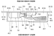
- FIG. 3 is a diagram showing an internal structure of the airbag device according to the first embodiment.
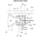
- FIG. 4 is a diagram illustrating a detailed structure of the diffuser portion of the gas generator according to the first embodiment and its surroundings.
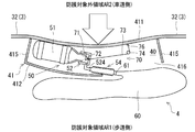
- FIG. 5 is a diagram illustrating an operating state of the airbag device according to the first embodiment.
- FIG. 6 is a diagram illustrating an operating state of the airbag device according to the first embodiment.
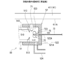
- FIG. 7 is a diagram showing a state in which the activation piece pulled by the operating wire is separated from the support in the airbag device according to the first embodiment.
- FIG. 1 is a perspective view of a guardrail according to the first embodiment.
- FIG. 2 is a perspective view of the guardrail according to the first embodiment.
- FIG. 3 is a diagram showing an internal structure of the airbag device according to the first embodiment.
- FIG. 8 is a diagram schematically showing an airbag bag body after being deployed in the protected area in the first embodiment.
- FIG. 9 is a diagram schematically showing an airbag bag body after being deployed in a protected area in the first embodiment.
- FIG. 10 is a perspective view of the guardrail according to the second embodiment.
- FIG. 11 is a diagram illustrating an internal structure of a support column in the guardrail according to the second embodiment.
- FIG. 12 is a diagram schematically showing an airbag bag body after being deployed in a protected area in the guardrail according to the second embodiment.
- FIG. 13 is a diagram illustrating an airbag bag body according to a modified example of the second embodiment.
- FIG. 14 is a diagram illustrating an airbag bag body according to a modified example of the second embodiment.
- FIG. 15 is a diagram illustrating a protective body according to another embodiment.
- FIG. 16 is a diagram illustrating a protective body according to another embodiment.
- FIG. 1 and 2 are perspective views of a guardrail 1 as a protective body including the airbag device according to the first embodiment.
- FIG. 1 is a perspective view of the guardrail 1 as viewed from the front side.
- FIG. 2 is a perspective view of the guardrail 1 as viewed from the rear side.
- the guardrail 1 includes a plurality of columns 2, a beam 3 supported between the columns 2, an airbag device 4, and the like.
- the guardrail 1 is an example of a protective body fixed to the ground GR.
- the guardrail 1 is installed at a boundary position between the sidewalk and the roadway, and extends along the boundary position.
- the guardrail 1 is a protective body that divides the space into a protection target area AR1 and a non-protection target area AR2 in order to protect the protection target area AR1 located on the sidewalk side. Suppresses entry into the target area AR1.
- FIGS. 1 and 2 for convenience of explanation, a part of the guardrail 1, that is, a pair of columns 2 and a beam 3 erected between the columns 2 are shown.
- the support column 2 is, for example, a cylindrical steel support column having a hollow structure inside.
- the beam 3 is, for example, a steel plate beam formed by bending a steel plate.
- the beam 3 is an example of a protective partition member, and extends along a boundary between a protected area AR1 which is a space on the sidewalk side and an unprotected area AR2 which is a space on the roadway side.
- the beam 3 has a protective inner surface 31 facing the protected area AR1 and a protective outer surface 32 facing the non-protected area AR2.
- the support column 2 is joined to the protection inner surface 31 of the beam 3 so that the support column 2 is arranged in the protection target area AR1.
- the beam 3 is attached to the support column 2 by, for example, a fixture 5.
- the protection outer surface 32 side facing the protection target area AR2 will be referred to as the front side of the guardrail 1 (beam 3), and the protection inner surface 31 side facing the protection target area AR1 will be described as the back side of the guardrail 1 (beam 3).
- the direction in which the support column 2 extends with respect to the ground GR will be described as the vertical direction of the guardrail 1.
- the beam 3 has a central recess 33 formed in the central portion in the height direction, which is recessed toward the back side when viewed from the front side.
- the central recess 33 extends along the extending direction (longitudinal direction) of the beam 3.
- the shapes of the beam 3 and the support column 2 are not particularly limited.
- the guardrail 1 is provided with an airbag device 4 for protecting pedestrians and the like located on the sidewalk (protected area AR1) when, for example, a vehicle traveling on a roadway comes into contact with or collides with the guardrail 1. ..
- an airbag device 4 for protecting pedestrians and the like located on the sidewalk (protected area AR1) when, for example, a vehicle traveling on a roadway comes into contact with or collides with the guardrail 1. ..
- the details of the airbag device 4 will be described.
- FIG. 3 is a diagram showing the internal structure of the airbag device 4 according to the first embodiment.
- the airbag device 4 has a steel outer shell case 41, and an accommodating portion 40 as an accommodating space for accommodating various parts of the airbag device 4 is formed inside the outer shell case 41.
- the outer shell case 41 is an example of the outer shell portion.
- the outer shell case 41 (accommodating portion 40) of the airbag device 4 may be arranged inside the guardrail 1 or may be attached to the outside of the guardrail 1. As shown in FIGS. 1 and 2, in the present embodiment, an example in which the outer shell case 41 (accommodation portion 40) of the airbag device 4 is attached to the beam 3 in the guardrail 1 will be described.
- the outer shell case 41 of the airbag device 4 is arranged in the vicinity of the central portion of the span sandwiched between the pair of columns 2 in the beam 3. Further, the outer shell case 41 of the airbag device 4 is provided in the central recess 33 of the beam 3.
- the outer shell case 41 has a front wall 411, a rear wall 412, an upper wall 413, a lower wall 414, a pair of left and right side walls 415, and the like.
- a bag outlet 416 is formed in the rear wall 412 of the outer shell case 41, and the bag outlet 416 is shielded by a cover member 417.
- the cover member 417 is made of a material having a lower strength than each steel wall body forming the outer shell case 41, for example, a thin resin material.
- a part of the outer shell case 41 may be formed of a steel plate forming the beam 3. In other words, a part of the steel plate forming the beam 3 may also serve as a part or the whole of the outer shell case 41.
- the gas generator 50, the airbag bag body 60, the operating mechanism 70, and the like are housed inside the outer shell case 41, that is, in the housing part 40.
- the airbag bag body 60 is arranged in a folded state at a predetermined position in the accommodating portion 40.
- the mode of the airbag bag body 60 in the accommodating portion 40 is not particularly limited.
- the airbag bag body 60 in the accommodating portion 40 may be folded by a bellows fold, may be folded by a roll fold, or may be folded in another form.
- the airbag bag body 60 may be positioned at a predetermined position of the accommodating portion 40 by being held by an appropriate holding member (not shown) provided on the inner wall surface of the outer shell case 41, for example. good. Further, as shown in FIG.
- FIG. 3 shows the arrangement position of the airbag bag body 60 and the position of the cover member 417 in a state of being housed in the outer shell case 41.
- the size etc. are specified. Note that FIG. 3 shows the state of the airbag device 4 before the gas generator 50 is activated.
- the type of the gas generator 50 is not particularly limited, but the gas generator 50 in the present embodiment is a stored gas type gas generator having a filling bottle 51 filled with pressurized gas.
- the filling bottle 51 When the filling bottle 51 is opened when the gas generator 50 is operated, pressurized gas is supplied to the airbag bag body 60, and the airbag bag body 60 expands.
- an appropriate gas suitable for expanding and expanding the airbag bag body 60 such as argon or helium, can be used.
- the filling bottle 51 of the gas generator 50 is fixed to the outer shell case 41 by an appropriate fixing member 53. In the example shown in FIG. 3, the filling bottle 51 of the gas generator 50 is fixed to the inner wall surface 411A of the front wall 411 of the outer shell case 41. However, the filling bottle 51 of the gas generator 50 may be fixed to another wall surface of the outer shell case 41.
- the bag outlet 416 of the outer shell case 41 in the airbag device 4 is opened in the rear wall 412 facing the protected area AR1 located on the sidewalk side.
- the bag outlet 416 is an opening for deploying the airbag bag body 60 to the outside of the outer shell case 41 (accommodation portion 40) when the gas generator 50 is operated.
- the cover member 417 that shields the bag outlet 416 of the outer shell case 41 is the airbag bag body 60 in the process of expanding the airbag bag body 60 by the pressurized gas supplied from the filling bottle 51 when the gas generator 50 is operated. It comes off the rear wall 412 or is destroyed by the expansion pressure of. As a result, the bag outlet 416 is opened.
- the bag outlet 416 of the outer shell case 41 is opened by the expansion pressure of the airbag bag body 60, so that the inside and outside of the outer shell case 41 communicate with each other, and as a result, air is supplied to the protected area AR1 located on the sidewalk side.
- the bag bag body 60 is deployed.
- the cover member 417 in the outer shell case 41 is simplified with respect to the rear wall 412 so that the cover member 417 can be detached from the rear wall 412 to the outside by the expansion pressure of the airbag bag body 60 when the gas generator 50 is operated. It may be attached as a target. Further, a fragile portion (for example, a tear line) having a thickness smaller than that of other portions of the cover member 417 may be extended at an appropriate position on the cover member 417. In this case, when the gas generator 50 is operated, the cover member 417 is broken by the expansion pressure of the airbag bag body 60 starting from the fragile portion, so that the bag outlet 416 is opened.
- a fragile portion for example, a tear line
- the gas generator 50 has a filling bottle 51 filled with pressurized gas, a diffuser portion 52 provided on the outlet end portion 511 side of the filling bottle 51, and the like.
- the filling bottle 51 and the diffuser portion 52 are made of a metal such as stainless steel.
- the filling bottle 51 and the diffuser portion 52 may be joined to each other by welding or the like, or may be integrally molded.
- FIG. 4 is a diagram illustrating a detailed structure of the diffuser portion 52 of the gas generator 50 according to the first embodiment and its surroundings.
- a pressurized gas chamber 510 is formed inside the filling bottle 51, and the pressurized gas chamber 510 is filled with the pressurized gas.
- the outlet end portion 511 of the filling bottle 51 has a tubular shape, and the gas discharge port 512 is opened at the outlet end portion 511.
- the outlet end portion 511 of the filling bottle 51 is provided with a closing member 513 such as a burst disk that closes the gas discharge port 512.
- the closing member 513 is formed of a thin-walled disk made of metal such as iron or stainless steel, and seals the gas discharge port 512. Further, in the example shown in FIG. 4, the closing member 513 is deformed into a bowl shape toward the diffuser chamber 523 side of the diffuser portion 52 by receiving the pressure of the pressurized gas filled in the pressurized gas chamber 510.
- the diffuser portion 52 is, for example, a member having a bottomed tubular shape, and includes a tubular wall portion 521 and a bottom wall portion 522 that closes an end portion of the tubular wall portion 521, and is hollow inside.
- a diffuser chamber 523 is formed.
- the closing member 513 that closes the gas discharge port 512 of the filling bottle 51 is arranged so that its outer surface 513A faces the diffuser chamber 523.
- the pressurized gas in the pressurized gas chamber 510 flows out from the gas discharge port 512 to the diffuser chamber 523.
- a discharge pipe 524 having a hollow tubular shape for discharging pressurized gas from the diffuser chamber 523 is connected to the tubular wall portion 521 of the diffuser portion 52.
- An internal passage for passing the pressurized gas is formed inside the discharge pipe 524.
- the discharge pipe 524 may be connected to the bottom wall portion 522, for example, as long as the pressurized gas for supplying the pressurized gas from the filling bottle 51 to the airbag bag body 60 can be discharged from the diffuser chamber 523.
- a communication hole 521A is formed at a position where the discharge pipe 524 is connected, and the communication hole 521A communicates the internal passage of the discharge pipe 524 with the diffuser chamber 523. Has been done.
- a gas discharge port 524A for discharging the pressurized gas flowing from the diffuser chamber 523 toward the airbag bag body 60 is formed.
- the air bag body 60 has a gas introduction port 61 for introducing pressurized gas inside, and the gas discharge port 524A in the discharge pipe 524 and the gas introduction port 61 in the airbag bag body 60 are flexible. It is airtightly connected by a connecting pipe 54 having a (see FIG. 3).
- the connecting pipe 54 may be, for example, a bellows-shaped flexible hose.
- the operating mechanism 70 includes a support 71, a starting piece 72 as a starting portion, an operating wire 73 as a transmission member, a pulley 74, and the like.
- the support 71 is a member that supports the activation piece 72, and is fixed to the tubular wall portion 521 of the diffuser portion 52.
- the support 71 extends from the tubular wall portion 521 toward the radial center side in the diffuser chamber 523, and the activation piece 72 is integrated with the fragile portion 711 formed at the tip of the support 71. It is connected.
- the fragile portion 711 formed at the tip of the support 71 is made of a material that is fragile to an external force, and its cross section is smaller than the cross section of the activation piece 72.
- the starting piece 72 has a first surface 721 facing the outer surface 513A of the closing member 513 and a second surface 722 facing the opposite side.
- the first surface 721 and the second surface 722 of the activation piece 72 are formed as flat surfaces.
- the strength of the closing member 513 is set so that the burst pressure when the closing member 513 is cleaved is smaller than the filling pressure of the pressurized gas. In other words, the strength of the closing member 513 is set to such an extent that it cannot withstand the filling pressure of the pressurized gas. Then, the activation piece 72 supported by the support 71 in the operating mechanism 70 supports the closing member 513 from the diffuser chamber 523 side, so that the opening of the closing member 513 is suppressed.
- the closing member 513 is suppressed from being cleaved as long as it is supported by the starting piece 72, but is cleaved when the supporting force from the starting piece 72 is lost.
- the position where the starting piece 72 is arranged in the initial state before the operation of the gas generator 50 is defined as the “initial position P1”. That is, in the initial state in which the starting piece 72 is arranged at the initial position P1, the starting piece 72 supports the closing member 513 from the diffuser chamber 523 side, thereby suppressing the cleavage of the closing member 513.
- first end portion 731 of the actuating wire 73 is fixed to the second surface 722 of the actuating piece 72 of the actuating mechanism 70.
- the first end portion 731 of the operating wire 73 may be moored to a fixture 723 such as a circular ring member fixed to the second surface 722 of the activation piece 72, for example.
- a seal member 75 is provided at the first end portion 731 of the operating wire 73.
- the seal member 75 may have, for example, a disk shape.
- the second end portion 732 which is the end portion of the operating wire 73 opposite to the first end portion 731, is fixed to the inner wall surface of the outer shell case 41 (see FIG. 3). In the example shown in FIG.
- the second end portion 732 of the operating wire 73 is fixed to the fixture 76 provided on the inner wall surface 411A of the front wall 411 of the outer shell case 41.
- the fixture 76 is an example of the fixing portion.
- the fixture 76 may be, for example, a circular ring member provided on the inner wall surface of the outer shell case 41, or the second end portion 732 of the operating wire 73 may be moored to the fixture 76.
- the operating wire 73 is formed of a metal wire, but it may be formed of another material. Further, as shown in FIG. 3, the operating wire 73 is bridged to a pulley 74 provided in the accommodating portion 40 in the outer shell case 41.
- the pulley 74 is a fixed pulley, and has a disk that guides the direction of the operating wire 73 that is bridged over the pulley 74, and a rotating shaft that rotatably supports the disk.
- the rotation shaft of the pulley 74 is fixed to, for example, the upper wall 413 or the lower wall 414 of the outer shell case 41.
- an insertion hole 522A through which the operating wire 73 is inserted is formed in the bottom wall portion 522 of the diffuser portion 52.
- the insertion hole 522A penetrates the bottom wall portion 522 in the material thickness direction.
- the insertion hole 522A has an inner diameter larger than the diameter of the operation wire 73, and the operation wire 73 is slidable along the inner peripheral surface of the insertion hole 522A.
- the inner diameter of the insertion hole 522A in the diffuser portion 52 is set to a dimension smaller than the diameter of the seal member 75.
- the operation contents of the airbag device 4 provided in the guardrail 1 will be described.
- the airbag device 4 of the present embodiment for example, when a vehicle traveling on a roadway (non-protection target area AR2) comes into contact with or collides with a guardrail 1, the gas generator 50 operates and the protection target is located on the sidewalk side. Pedestrians and the like are protected by deploying the airbag bag body 60 in the area AR1. More specifically, in the airbag device 4, the beam 3 and the outer shell case 41 installed on the beam 3 are deformed by an external force caused by a vehicle or the like coming into contact with or colliding with the guardrail 1 from the roadway side.
- the operating mechanism 70 functions, and the operating mechanism 70 operates the gas generator 50 by utilizing the external force acting on the outer shell case 41.
- FIG. 5 is a diagram illustrating an operating state of the airbag device 4 according to the first embodiment.
- the outer shell case 41 installed on the beam 3 is deformed due to the external force accompanying the collision of the vehicle.
- the front wall 411 mainly facing the roadway (non-protected area AR2) side is deformed so as to be curved toward the protected area AR1 side.
- the wire path length of the operating wire 73 is the path of the operating wire 73 from the fixture 76 provided on the inner wall surface 411A of the front wall 411 of the outer shell case 41 to the fixture 723 provided on the activation piece 72. It is long. In the present embodiment, since the operating wire 73 is stretched on the pulley 74, the wire path length of the operating wire 73 is the linear distance between the fixture 76 and the pulley 74 and the linear distance between the fixture 723 and the pulley 74. It roughly matches the sum with the distance.
- the operating wire 73 transmits the tension (external force) associated with the collision of the vehicle with the guardrail 1 from the fixture 76 of the front wall 411 to the fixture 723 of the starting piece 72.
- the activation piece 72 arranged in the diffuser chamber 523 is pulled by the actuating wire 73 in the direction of the arrow F shown in FIG. 6, that is, in the direction away from the closing member 513.
- the fragile portion 711 of the support 71 is torn and destroyed, and the activation piece 72 is separated (separated) from the support 71.
- the starting piece 72 is displaced from the initial position P1 described with reference to FIG. 4 to a starting position P2 different from the initial position P1.
- FIG. 7 is a diagram showing a state in which the starting piece 72 pulled by the operating wire 73 is separated from the support 71 in the airbag device 4 according to the first embodiment.
- the starting piece 72 when the starting piece 72 is displaced from the initial position P1 to the starting position P2, the starting piece 72 loses the supporting force that previously supported the closing member 513, and the filling bottle 51 (pressurized gas chamber)
- the closing member 513 cannot withstand the filling pressure of the pressurized gas filled in 510), and the closing member 513 is cleaved.
- the gas discharge port 512 in the filling bottle 51 is opened, and the pressurized gas in the pressurized gas chamber 510 is discharged from the gas discharge port 512 to the diffuser chamber 523. That is, the gas generator 50 operates.
- the seal member 75 is attached to the first end portion 731 of the actuating wire 73, and the inner diameter of the insertion hole 522A in the bottom wall portion 522 of the diffuser portion 52 is larger than the diameter of the seal member 75. small. Therefore, after the starting piece 72 is separated from the support 71, as shown in FIG. 7, the seal member 75 provided at the first end portion 731 of the operating wire 73 serves as a stopper to prevent the diffuser portion 52 from coming off. The insertion hole 522A in the bottom wall portion 522 is closed.
- the pressurized gas discharged from the gas discharge port 512 of the filling bottle 51 to the diffuser chamber 523 passes through the communication hole 521A, the discharge pipe 524, and the connecting pipe 54 formed in the tubular wall portion 521. It is supplied from the gas inlet 61 of the airbag bag body 60 to the inside of the airbag bag body 60 (see FIG. 3 and the like). In this way, by starting the supply of the pressurized gas to the airbag bag body 60 arranged in the accommodating portion 40, the expansion of the airbag bag body 60 is started.
- the expansion pressure of the airbag bag body 60 acts on the cover member 417 that shields the bag outlet 416 of the outer shell case 41.
- the cover member 417 is pressed from the inside to the outside, detached from the rear wall 412, or destroyed.
- the bag outlet 416 is opened, and the airbag bag body 60 that expands due to the supply of pressurized gas is expanded from the bag outlet 416 to the outside of the outer shell case 41 (accommodation portion 40). Can be done.
- FIG. 5 shows a state in which the airbag bag body 60 is being deployed in the protected area AR1 (sidewalk).
- FIG. 8 and 9 are diagrams schematically showing the airbag bag body 60 after being deployed in the protected area AR1 (sidewalk) in the first embodiment.
- FIG. 8 schematically shows a state in which the guardrail 1 is viewed from above
- FIG. 9 schematically shows a state in which the guardrail 1 is viewed from the side surface side.
- the guardrail 1 in the present embodiment operates the airbag device 4 (gas generator 50) when a large external force acts on the guardrail 1, such as when a colliding object such as a vehicle collides, and protects the protected area AR1 (sidewalk).
- the airbag bag body 60 can be deployed in the air bag.
- a protected object such as a pedestrian in the protected area AR1 (sidewalk). That is, according to the guardrail 1, the safety of the protected area AR1 (sidewalk) can be further ensured.
- the guardrail 1 in the present embodiment in the normal state (before the operation of the airbag device 4), the airbag bag body 60 is compactly housed inside the outer shell case 41 in a folded state. , The guardrail 1 can be made less bulky. Therefore, it is difficult to obstruct the passage of pedestrians. Further, as described above, in the normal state (before the operation of the airbag device 4), since the airbag bag body 60 is housed inside the outer shell case 41, the airbag bag body 60 is exposed to ultraviolet rays for a long period of time. , It is possible to suppress exposure to rain and wind. Therefore, even when the guardrail 1 is used for a long period of time, it is possible to prevent the airbag bag body 60 from deteriorating. Thereby, it is possible to provide the guardrail 1 in which the protective performance does not deteriorate for a long period of time.
- the guardrail 1 in the present embodiment is a method of expanding and deploying the airbag bag body 60 by using the gas supplied from the gas generator 50, it is possible to suppress an excessive increase in the weight of the guardrail 1. Therefore, it is not necessary to increase the mounting structure for attaching the beam 3 to the support column 2 or to increase the strength, and the material cost is unlikely to increase excessively. From the above, according to the guardrail 1 in the present embodiment, the safety of the protected area AR1 can be further ensured as compared with the conventional case, and the guardrail 1 is excessively bulky or has an excessive increase in weight. It is possible to provide a protective body fixed to the ground without deteriorating the protective performance for a long period of time.
- the unfolding width (height dimension) Ha in the height direction after unfolding is larger than the height dimension Hb of the beam 3 as a protective partition member. It is designed to be. According to such an airbag bag body 60, the entire beam 3 in the height direction can be covered by the airbag bag body 60 after deployment. Therefore, pedestrians in the protected area AR1 (sidewalk) can be protected more safely.
- the gas generator 50 housed in the outer shell case 41 (accommodating portion 40) is arranged at a position not facing the cover member 417. There is.
- the gas generator 50 so as not to face the cover member 417 whose strength is lower than that of the wall body forming the outer shell case 41, gas is generated when a vehicle or the like violently collides with the guardrail 1. Even if the housing of the generator 50 (filled bottle 51 in this embodiment) is damaged by any chance, the safety of the surroundings can be secured even more appropriately.
- the airbag bag body 60 is arranged in the accommodating portion 40 so as to face the cover member 417 of the outer shell case 41, the airbag bag body is arranged in the accommodating portion 40. In the process of expansion of 60, the expansion pressure of the airbag bag body 60 is likely to act on the cover member 417, and the bag outlet 416 of the outer shell case 41 can be smoothly opened.
- the airbag device 4 of the guardrail 1 in the present embodiment utilizes an external force that deforms the outer shell case 41 when the outer shell case 41 is deformed by an external force when a colliding object such as a vehicle collides with the guardrail 1. It includes an operating mechanism 70 that operates the gas generator 50 by a mechanical mechanism. According to this, it is not necessary to secure a power source for operating the gas generator 50. Therefore, the airbag device 4 in the present embodiment is particularly suitable as an airbag device installed on a protective body fixed to the ground where it is not easy to secure a power source. Further, according to the airbag device 4 in the present embodiment, a sensor for detecting a collision of a colliding object with the guardrail 1 is also unnecessary.
- the airbag device 60 can be operated without using electric power, and the airbag bag body 60 can be expanded and deployed, so that there are restrictions on the installation location.
- the guardrail 1 can be installed without. That is, by applying the airbag device 4 in the present embodiment, it is possible to provide a guardrail 1 having a very high degree of freedom regarding the installation location.
- the arrangement position of the fixture 76 in the outer shell case 41 (outer shell portion) and the initial position P1 of the activation piece 72 (starting portion) are the beam 3 (protective partition member).
- the operating wire 73 (transmission member) is extended along the extension direction of the beam 3 (protective partition member).
- the seal member 75 provided at the first end portion 731 of the operating wire 73 is provided. It is configured to prevent the bottom wall from coming off and to close the insertion hole 522A in the bottom wall portion 522. As a result, it is possible to prevent the pressurized gas discharged from the filling bottle 51 into the diffuser chamber 523 from leaking from the insertion hole 522A. At that time, the seal member 75 positioned in the insertion hole 522A in the diffuser portion 52 has a bottom wall portion due to the pressure of the pressurized gas while the pressurized gas is being supplied from the filling bottle 51 to the diffuser chamber 523.
- the pressurized gas can be quickly supplied from the gas generator 50 (filled bottle 51) to the airbag bag body 60 to expand the airbag bag body 60. Further, it is possible to prevent the amount of pressurized gas supplied from the gas generator 50 (filled bottle 51) to the airbag bag body 60 from being reduced.
- the gas discharge port 524A in the discharge pipe 524 and the gas introduction port 61 in the airbag bag body 60 are connected by a flexible connecting pipe 54. Therefore, when a vehicle or the like collides with the guardrail 1, even if the outer shell case 41 is significantly deformed, the flow path of the pressurized gas supplied from the gas generator 50 side to the airbag bag body 60 may be blocked or excessive. It is possible to preferably suppress the narrowing of the gas.
- the connecting pipe 54 does not necessarily have to have flexibility.
- the discharge pipe 524 is directly connected to the gas introduction port 61 of the airbag bag body 60 without interposing the connecting pipe 54 between the discharge pipe 524 of the diffuser portion 52 and the gas introduction port 61 of the airbag bag body 60. You may connect to the target.
- the pulley 74 may be a tension pulley (tensioner) that applies tension to the operating wire 73.
- tension pulley tensioner
- the pulley 74 that functions as a tensioner in the operating mechanism 70, it is possible to prevent the operating wire 73 from bending. As a result, when a vehicle or the like collides with the guardrail 1, tension is likely to be generated in the operating wire 73, and the airbag device 4 (gas generator 50) can be operated with high accuracy.
- the pulley 74 When the pulley 74 is a tension pulley, the magnitude of the tension (initial tension) that the pulley 74 (tensioner) acts on the operating wire 73 in the initial state before the vehicle or the like collides with the guardrail 1 is determined by the diffuser chamber.
- the starting piece 72 arranged at 523 is set to be smaller than the working tension acting on the working wire 73 when the starting piece 72 is displaced from the initial position P1 to the starting position P2.
- the airbag device 4 gas generator 50
- the tensioner that exerts tension on the operating wire 73 may be arranged separately from the pulley 74.
- the deployment mode of the airbag bag body 60 for example, the shape, position, size, etc. of the airbag bag body 60 after deployment is not particularly limited. .. Further, the installation location, the number of installations, and the like of the airbag device 4 on the guardrail 1 are not particularly limited.
- the operating wire 73 which is a wire rod, is used as the transmission member in the operating mechanism 70, but the present invention is not limited to this.
- a band material may be used instead of the operating wire 73 to transmit the external force acting on the outer shell case 41 from the fixture 76 provided on the outer shell case 41 to the activation piece 72, and the transmission function may be transmitted.
- Various forms can be adopted as long as they are exhibited.
- the burst pressure of the closing member 513 that seals the gas discharge port 512 of the filling bottle 51 in the gas generator 50 is set to a value smaller than the filling pressure of the pressurized gas, and the vehicle or the like is a guardrail.
- the closing member 513 was directly supported by the starting piece 72 to suppress the cleavage of the closing member 513, but the present invention is not limited to this mode.
- the initial position P1 in which the starting piece 72 of the operating mechanism 70 is arranged in the initial state may be separated from the closing member 513.
- the burst pressure of the closing member 513 is set to be larger than the filling pressure of the pressurized gas so that the closing member 513 is not cleaved by the filling pressure of the pressurized gas.
- the operating mechanism 70 separately has an opening mechanism for opening the closing member 513 in conjunction with the opening mechanism.
- the opening mechanism as described above includes, for example, a detonator that houses the detonator inside and a firing pin (trigger) that is urged by a spring or the like so as to collide with the detonator, and opens the activation piece 72 in the initial state. It may be engaged with the firing pin of the mechanism to prevent the firing pin from colliding with the detonator against the urging force of the spring.
- the detonator contained in the chamber of a detonator is an explosive that burns when pressure is applied.
- the firing pin vigorously collides with the detonator due to the urging force of the spring, and the detonator of the detonator burns. Can be cleaved.
- the opening mechanism may have a detonator chamber for accommodating a detonator different from the detonator detonator, and the detonator chamber and the detonator chamber may be communicated with each other by a detonator (flash hole). ..
- the flame or combustion gas generated by the combustion of the detonator in the detonator may be introduced into the explosive chamber through the ignition hole, and the explosive may be ignited by the thermal energy. Then, the closing member 513 may be cleaved by the thermal energy of the flame or the combustion gas generated by the combustion of the explosive.
- the firing pin is restricted from colliding with the detonator.
- the gas discharge port 512 of the filling bottle 51 is maintained in a state of being sealed by the closing member 513.
- the starting piece 72 is displaced from the initial position P1 to the starting position P2 by the operating wire 73, the engagement between the starting piece 72 and the firing pin is released.
- the firing pin vigorously collides with the detonator due to the urging force of the spring, so that the detonator of the detonator is ignited and the closing member 513 is cleaved.
- the gas discharge port 512 of the filling bottle 51 can be opened and the gas generator 50 can be operated.
- a cleaving member formed of a rod member or an arrowhead member having a sharp tip is closed by using an urging force such as a spring.
- a mode may be adopted in which the closing member 513 is directly cleaved by the impact of the collision with the member 513.
- the stopper member configured as the starting portion is engaged with the cleaving member, and the cleaving member is fired toward the closing member 513. It may be regulated against the urging force of the spring.
- the stopper member (starting portion) is connected to the first end portion 731 of the operating wire 73, and when a vehicle or the like collides with the guardrail, the stopper member (starting portion) is pulled by the operating wire 73 to open the stopper member (starting portion). It is displaced from the initial position P1 that engages with the member to the starting position P2 that releases the engaged state. With this as an opportunity, the cleaving member is fired toward the closing member 513 by the urging force of the spring, and the cleaving member vigorously collides with the closing member 513 to cleave the closing member 513 and exhaust the gas of the filling bottle 51. Exit 512 may be opened.
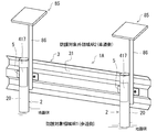
- FIG. 10 is a perspective view of the guardrail 1A according to the second embodiment.
- FIG. 10 shows a state in which the guardrail 1A is viewed from the rear side, and the same reference reference numerals are given to the configurations common to those in the first embodiment, and detailed description thereof will be omitted.
- the beam 3 is supported by the support column 2 as in the guardrail 1 according to the first embodiment. Further, the support column 2 is joined to the protection inner surface 31 of the beam 3 so that the support column 2 is arranged in the protection target area AR1. Further, in the guardrail 1A in the present embodiment, the airbag device 4A is provided not on the beam 3 but on the support column 2.
- the strut 2 has a hollow structure inside, and a housing portion 40 for accommodating various parts of the airbag device 4A is formed inside the strut 2.
- Reference numeral 20 shown in FIG. 10 is a cylindrical wall in the support column 2, and an accommodating portion 40 is formed inside the cylindrical wall 20.
- the cylindrical wall 20 in which the accommodating portion 40 is formed inside is an example of the outer shell portion.
- a bag outlet 416 is formed at a position facing the protected area AR1 in the cylindrical wall 20 of the support column 2, and the bag outlet 416 is shielded by the cover member 417.
- the guardrail 1A includes a photovoltaic power generation unit 85.
- a photovoltaic power generation panel that generates electricity by solar energy is arranged on the upper surface, and is attached to the guard rail 1A in a state of being supported by the upper end of a pole-shaped support pole 86.
- the support pole 86 may be attached to, for example, a fixture 5 that attaches the beam 3 to the support column 2.
- the electric power generated by the photovoltaic power generation unit 85 is used to operate the airbag device 4A provided on the support column 2. Therefore, the support pole 86 that supports the photovoltaic power generation unit 85 is installed in the vicinity of the support column 2 that houses the airbag device 4A.
- FIG. 11 is a diagram illustrating the internal structure of the support column 2 in the guardrail 1A according to the second embodiment.
- the accommodating portion 40 formed inside the cylindrical wall 20 accommodates a gas generator 50A, an airbag bag 60, a control unit 80, a power supply 81, a collision detection sensor 82, and the like.
- the gas generator 50A, the airbag bag body 60, the control unit 80, the power supply 81, and the collision detection sensor 82 are predetermined in the accommodating portion 40 by an appropriate fixing member (not shown) provided on the inner wall surface of the cylindrical wall 20. It is fixed in position.
- the type of the gas generator 50A is not particularly limited.
- the gas generator 50A has an electric igniter (not shown), ignites a gas generator by operating the electric igniter, cools the generated gas with a coolant, and then forms a gas discharge port in a housing. It is ejected from 512A.
- the gas generator 50A may be a stored gas type gas generator having a filling bottle 51 filled with pressurized gas, as in the first embodiment.
- the airbag bag body 60 is arranged in the vicinity of the gas generator 50A in a folded state in the accommodating portion 40. Then, when the gas generator 50A is in operation, the gas ejected from the gas discharge port 512A of the gas generator 50A is supplied to the airbag bag body 60 to expand the gas generator 50A. Further, as shown in FIG. 11, the airbag bag body 60 is arranged at a position facing the bag outlet 416 and the cover member 417 formed on the cylindrical wall 20 of the support column 2.
- the control unit 80 is a control unit for controlling the gas generator 50A, and is connected to the electric igniter, the power supply 81, the collision detection sensor 82, etc. of the gas generator 50A via a lead wire or the like.
- the collision detection sensor 82 is a sensor for detecting that a collision object such as a vehicle has collided with the guardrail 1A, and a known airbag sensor can be applied.
- the power supply 81 is, for example, a secondary battery (storage battery).
- the power supply 81 is connected to the photovoltaic power generation unit 85 by a lead wire, and stores the electric power generated by the photovoltaic power generation unit 85.
- control unit 80 has a microcomputer or the like for determining the collision level detected by the collision detection sensor 82 based on the signal input from the collision detection sensor 82.
- the control unit 80 determines the collision level based on the signal received from the collision detection sensor 82, and when it determines that the airbag bag body 60 needs to be inflated, sends an operation signal to the electric igniter of the gas generator 50A. Feed and activate the electric igniter.
- the control unit 80 may determine that the vehicle has collided with the guardrail 1A and operate the gas generator 50A. ..
- the control unit 80 may set the reference impact level for the above determination so as not to operate when the guardrail 1A is kicked by a person.
- the gas generator 50A operates based on the operation signal from the control unit 80, the gas generated in the gas generator 50A is ejected from the gas discharge port 512A, and the gas is supplied to the airbag bag body 60.
- the collision detection sensor 82 may be mounted on the control unit 80.
- the airbag bag body 60 When the gas supply to the airbag bag body 60 is started from the gas generator 50A, the airbag bag body 60 first expands in the accommodating portion 40. Then, in the process of expanding the airbag bag body 60 in the accommodating portion 40, the expansion pressure of the airbag bag body 60 acts on the cover member 417 that shields the bag outlet 416 of the cylindrical wall 20 in the support column 2. When the cover member 417 is removed from or destroyed from the cylindrical wall 20, the bag outlet 416 is opened. As a result, the airbag bag body 60 can be deployed from the bag outlet 416 to the outside of the cylindrical wall 20 (accommodation portion 40). Since the bag outlet 416 of the cylindrical wall 20 in the support column 2 faces the protected area AR1 (sidewalk), the airbag bag body 60 can be deployed in the protected area AR1 (sidewalk).
- FIG. 12 is a diagram schematically showing an airbag bag body 60 after being deployed in the protected area AR1 (sidewalk) in the guardrail 1A according to the second embodiment.
- FIG. 12 shows a state in which the guardrail 1 is viewed from above. Further, in FIG. 12, for convenience, the solar power generation unit 85 and the support pole 86 are not shown.
- the airbag device 4A gas generator 50A
- the protection target area AR1 protection target area AR1
- the airbag bag body 60 is deployed on the sidewalk.
- the power source 81 is a secondary battery (storage battery) and the electric power generated by the photovoltaic power generation unit 85 is used as the operating power source of the airbag device 4A
- electric power may be supplied to the airbag device 4A from an external power source.
- the support column 2 is arranged in the protection target area AR1 by joining the support column 2 to the protective inner surface 31 of the beam 3.
- the cylindrical wall 20 of the support column 2 that supports the beam 3 is formed as an outer shell portion, and the gas generator 50A and the airbag are provided in the accommodating portion 40 formed inside the cylindrical wall 20.
- the bag body 60 and the like were accommodated, but the present invention is not limited to this.
- the outer shell case 41 according to the first embodiment may be attached to the outside of the support column 2, and the airbag bag body 60 may be deployed in the protected area AR1 (sidewalk) when the vehicle collides with the guardrail 1A. ..
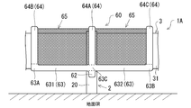
- FIGS. 13 and 14 are views for explaining the airbag bag body 60A according to the modified example of the second embodiment.
- FIG. 13 is a state in which the deployed airbag bag body 60A according to the modified example is viewed from the back side of the guardrail 1A
- FIG. 14 is a state in which the deployed airbag bag body 60A according to the modified example is viewed from above the guardrail 1A. The state is shown roughly.
- FIGS. 13 and 14 the illustration of the photovoltaic power generation unit 85 and the support pole 86 is omitted.
- the airbag bag body 60A shown in FIGS. 13 and 14 has an introduction unit 62 into which the gas supplied from the gas generator 50A is introduced when the gas generator 50A is operated, an arm portion 63 communicating with the introduction portion 62, and an arm. It includes a plurality of support portions 64 that communicate with the portion 63 at a plurality of locations, a cushioning material 65 attached to the outer surface of the airbag bag body 60A, and the like.
- the arm portion 63 is a portion that extends along the extending direction of the beam 3 as a protective partition wall member when deployed by the gas supplied from the introduction portion 62. Further, the support portion 64 is a portion extending in a direction intersecting the extending direction of the arm portion 63 when deployed by the gas supplied from the arm portion 63.
- three support portions 64 extend upward from both end portions 63A and 63B and the central portion 63C of the arm portion 63.
- the support portion 64 extending upward from the central portion 63C of the arm portion 63 is referred to as a central support portion 64A.
- the support portion 64 extending upward from the end portion 63A of the arm portion 63 is referred to as a first support portion 64B, and the support portion 64 extending upward from the end portion 63B of the arm portion 63 is referred to as a second support portion 64C.
- the region from the end portion 63A to the central portion 63C is referred to as the first arm region 631
- the region from the end portion 63B to the central portion 63C is referred to as the second arm region 632.
- the introduction portion 62, the arm portion 63, and each support portion 64 of the airbag bag body 60A communicate with each other, and the gas supplied from the gas generator 50A flows into the inside of the airbag bag body 60A from the introduction portion 62.
- the introduction portion 62, the arm portion 63, and the support portion 64 are sequentially supplied.
- the introduction portion 62, the arm portion 63, and the support portion 64 in the airbag bag body 60A expand and expand into the protected area AR1 (sidewalk).
- the airbag bag body 60A has a cushioning material 65 attached to its outer surface. Then, when the airbag bag body 60A is deployed, the cushioning material 65 is stretched over the area surrounded by the support portions 64 and the arm portions 63.
- the material of the cushioning material 65 is not particularly limited, but it is preferably formed of a cloth material or a net material having appropriate flexibility and durability.
- the cushioning material 65 may be made of the same material as the airbag fabric (base cloth) that forms the support portion 64, the arm portion 63, and the like.
- the cushioning material 65 attached to the outer surface of the airbag bag body 60A has a structure in which gas is not introduced.
- the airbag device 4A provided with the airbag bag body 60A according to this modification extends not only to the introduction portion 62, the arm portion 63, and the support portion 64, but also to the area surrounded by each support portion 64 and the arm portion 63.
- the hung cushioning material 65 can protect pedestrians and the like in the protected area AR1 (sidewalk). Since it is not necessary to introduce gas into the area where the cushioning material 65 is stretched after the airbag bag body 60A is deployed, the airbag does not supply a large amount of gas from the gas generator 50A to the airbag bag body 60A. A sufficient area that can be protected by the bag body 60A can be secured. Therefore, the airbag bag body 60A can be miniaturized. Further, the gas generator 50A that supplies gas to the airbag bag body 60A can be downsized.
- the airbag bag body 60A is configured so that the arm portion 63 has a V-shape when viewed from above after deployment, and the arm portion 63 after deployment has a V shape. It is designed to be separated from the support column 2 and the beam 3. That is, in the top view, the first arm region 631 and the second arm region 632 of the arm portion 63 are connected so as to form an angle smaller than 180 ° with the central support portion 64A as a reference. As a result, the cushioning material 65 in the airbag bag body 60A can be stretched at a position away from the support column 2 and the beam 3 in the guardrail 1A. That is, a cushioning space As can be formed between the cushioning material 65 and the beam 3 in the airbag bag body 60A developed in the protected area AR1 (sidewalk).
- the reference numeral D1 shown in FIG. 14 is an angle formed by the first arm region 631 and the second arm region 632 in the arm portion 63 (hereinafter, referred to as “arm portion angle”).
- the arm angle D1 may be set in the range of 150 ° or less, and by doing so, a sufficient cushioning space As is secured between the cushioning material 65 of the airbag bag body 60A and the beam 3 after deployment. can do.
- the protective body according to the present disclosure is applied to a guardrail installed along a road has been described as an example, but the protective body may be applied to a protective body other than the guardrail. That is, the protective body according to the present disclosure can be applied to various fences, protective fences, etc. that are fixed to the ground and partition the space into a protected area and a non-protected area. Further, it goes without saying that the protected area and the non-protected area partitioned by the protective body are not limited to the sidewalk and the roadway.
- the protective body may be a fence, a protective fence, or the like installed along the boundary between a work area where work is performed by a forklift or the like and a non-work area in a facility such as a factory or a warehouse.
- FIG. 15 and 16 are diagrams illustrating the protective body 1B according to another embodiment.
- FIG. 15 is a rear view of the protective body 1B
- FIG. 16 is a top view of the protective body 1B. Details of the same configuration as the guardrail according to the above-described embodiment are given by adding the same reference numerals.
- the protective body 1B has a protective partition member 3B extending along the boundary between the protected area AR1 and the non-protected area AR2, and a plurality of columns 2B supporting the protective partition member 3B.
- the protective partition member 3B includes a plurality of cross rail members 300 extending along the boundary between the protected area AR1 and the non-protected area AR2, and each cross rail member 300 moves up and down at regular intervals, for example. They are arranged side by side.
- Each cross rail member 300 has a protective inner surface 31 facing the protected area AR1 and a protective outer surface 32 facing the non-protected area AR2.
- the protective body 1B is, for example, a protective fence fixed to the floor surface (ground) in a facility such as a factory or a warehouse. Then, the protective body 1B is installed along the boundary position between the work area where the work by the forklift or the like is performed and the passage area where the employees or the like pass.
- the protective body 1B includes an airbag device 4B, and an outer shell case 41 of the airbag device 4B is attached to a protective inner surface 31 of the protective partition member 3B.
- the internal structure of the outer shell case 41 may be the same as the structure described in FIGS. 3 and 4 of the first embodiment, or may be the same as the structure described in FIG. 11 and the like of the second embodiment. .. Even in such a protective body 1B, when a colliding object collides with the protective body 1B, gas is supplied from the gas generator to the airbag bag body housed in the outer shell case 41, and the airbag bag body is used. By deploying to the protected area AR1, it is possible to safely protect a person in the protected area AR1.
- the protective partition member 3B in the protective body 1B may have a hollow structure, and an accommodating portion for accommodating the airbag bag body and the gas generator constituting the airbag device 4B may be formed inside the protective partition member 3B.
- the outer shell case 41 may be arranged on the support column 2B.
Landscapes
- Engineering & Computer Science (AREA)
- Architecture (AREA)
- Civil Engineering (AREA)
- Structural Engineering (AREA)
- Refuge Islands, Traffic Blockers, Or Guard Fence (AREA)
Abstract
地面に固定される防護体において、従来に比べて安全性に優れ、且つ、長期に亘って防護性能が低下することを抑制可能な技術を提供する。地面に固定され、空間を防護対象領域と防護対象外領域とに仕切るための防護体であって、ガス発生器と、ガス発生器の作動時に当該ガス発生器から供給されるガスによって膨張することで防護対象領域に展開するエアバッグ袋体と、ガス発生器およびエアバッグ袋体を収容する外殻部と、を備える。
Description
本発明は、防護体に関する。
地面に固定され、歩行者等の防護対象を保護するための防護体として、ガードレール、フェンス等が広く知られている。例えば、ガードレールは、車両の逸脱の防止等を目的として設けられる防護体であり、車道と歩道との境界部に沿って延設されることで空間を防護対象領域(例えば、歩道)と防護対象外領域(例えば、車道)とに仕切っている。
ガードレールは、一般的に、適度な剛性と靭性を有するビームと、当該ビームを支持する支柱によって構成され、車両等の衝突時の衝撃に対してビームと支柱の変形によってエネルギーを吸収する構造となっている。このようなガードレール等の防護体は、車両等の衝突物が衝突した際の衝突エネルギーを吸収するためにビームや支柱にある程度の変形が起こることを許容されて設計されている。そのため、ガードレール等の防護体に対して車両等の衝突物が衝突した際に防護体が大きく変形する場合もあり、防護対象領域(例えば、歩道)の安全性をより一層高めることのできる防護体が望まれている。
これに関連して、特許文献1には、支柱間に鋼製部材を架設したガードレールにおいて、鋼製部材の車道側側面に、内部に緩衝材を充填した緩衝部材を鋼製部材に沿って延在するように取り付け、ガードレールに接触した車両やガードレールの損傷の軽減を図る技術が開示されている。
しかしながら、特許文献1に開示されているガードレールは、鋼製部材の車道側側面を緩衝部材によって保護するものであり、歩道側を保護するものでない。また、ガードレールに取り付けた緩衝部材は外部に露出しているため、紫外線や雨風等に晒されることによって緩衝部材が劣化し、長期に亘って保護性能を維持することが困難となる虞がある。
本開示の技術は、上記した実情に鑑みてなされたものであり、その目的は、地面に固定される防護体において、従来に比べて安全性に優れ、且つ、長期に亘って防護性能が低下することを抑制可能な技術を提供することにある。
上記課題を解決するために、本開示の技術は以下の構成を採用した。すなわち、本開示の防護体は、地面に固定され、空間を防護対象領域と防護対象外領域とに仕切るための防護体であって、ガス発生器と、前記ガス発生器の作動時に当該ガス発生器から供給されるガスによって膨張することで前記防護対象領域に展開するエアバッグ袋体と、前記ガス発生器および前記エアバッグ袋体を収容する外殻部と、を備える。
ここで、前記外殻部は、前記ガス発生器の作動時に前記エアバッグ袋体を外部に展開させるためのバッグ出口を有し、前記バッグ出口が前記防護対象領域に面するように設けられていても良い。
また、本開示に係る防護体は、前記防護対象領域と前記防護対象外領域との境界部に沿って延設され、前記防護対象領域に面する防護内面と、前記防護対象外領域に面する防護外面と、を有する防護隔壁部材を含み、前記外殻部が前記防護隔壁部材に設けられていても良い。
また、本開示に係る防護体は、前記防護対象領域と前記防護対象外領域との境界部に沿って延設され、前記防護対象領域に面する防護内面と、前記防護対象外領域に面する防護外面と、を有する防護隔壁部材と、前記防護隔壁部材を支持する支柱と、を含み、前記外殻部が前記支柱に設けられていても良い。
また、前記支柱は、当該支柱が前記防護対象領域に配置されるように前記防護隔壁部材の前記防護内面に接合されていても良い。
また、前記エアバッグ袋体は、展開後における高さ方向への展開幅が、前記防護隔壁部材の高さ寸法よりも大きくても良い。
また、前記外殻部は、前記バッグ出口を遮蔽するカバー部材を有し、前記ガス発生器の作動時に前記エアバッグ袋体の膨張圧によって前記バッグ出口が開放されても良い。
また、前記カバー部材は、前記外殻部に比べて低強度であり、前記ガス発生器は、前記外殻部において前記カバー部材と対向しない位置に配置されていても良い。
また、前記エアバッグ袋体は、前記ガス発生器の作動時に当該ガス発生器から供給されるガスが導入される導入部と、前記導入部と連通し、前記導入部から供給されるガスによって展開する際に前記防護隔壁部材の延設方向に沿って延びる腕部と、前記腕部と複数箇所で連通し、前記腕部から供給されるガスによって展開する際に前記腕部の延設方向と交差する方向に延びる複数の支持部と、前記エアバッグ袋体の外面に取り付けられ、前記エアバッグ袋体が展開する際に前記複数の支持部および前記腕部で囲まれた領域に張架される緩衝材と、を有していても良い。
また、前記防護体は、歩道と車道との境界位置に設置されるガードレールであっても良い。
本開示に係る技術によれば、地面に固定される防護体において、従来に比べて安全性に優れ、且つ、長期に亘って防護性能が低下することを抑制可能な技術を提供できる。
以下に、図面を参照して本開示に係る防護体の実施形態について説明する。なお、各実施形態における各構成及びそれらの組み合わせ等は、一例であって、本発明の主旨から逸脱しない範囲内で、適宜、構成の付加、省略、置換、及びその他の変更が可能である。本開示は、実施形態によって限定されることはなく、請求の範囲によってのみ限定される。
<実施形態1>
図1および図2は、実施形態1に係るエアバッグ装置を備えた防護体としてのガードレール1の斜視図である。図1は、ガードレール1を正面側から眺めた斜視図である。図2は、ガードレール1を背面側から眺めた斜視図である。
図1および図2は、実施形態1に係るエアバッグ装置を備えた防護体としてのガードレール1の斜視図である。図1は、ガードレール1を正面側から眺めた斜視図である。図2は、ガードレール1を背面側から眺めた斜視図である。
ガードレール1は、複数の支柱2、支柱2間に支持されたビーム3、エアバッグ装置4等を備えている。ガードレール1は、地面GRに固定された防護体の一例である。ガードレール1は、歩道と車道との境界位置に設置されており、これらに沿って延設されている。ガードレール1は、歩道側に位置する防護対象領域AR1を防護するために、空間を防護対象領域AR1と防護対象外領域AR2とに仕切る防護体であり、接触あるいは衝突した車両等が歩道側の防護対象領域AR1に進入することを抑制する。図1、図2等においては、説明の便宜上、ガードレール1の一部、すなわち一対の支柱2と、支柱2間に架設されたビーム3を示している。
支柱2は、例えば、内部が中空構造として構成された円筒状の鋼製支柱である。また、ビーム3は、例えば鋼板を折り曲げ加工することで形成された鋼板ビームである。ビーム3は、防護隔壁部材の一例であり、歩道側の空間である防護対象領域AR1と車道側の空間である防護対象外領域AR2との境界部に沿って延設されている。ビーム3は、防護対象領域AR1に面する防護内面31と、防護対象外領域AR2に面する防護外面32を有している。また、支柱2は、当該支柱2が防護対象領域AR1に配置されるようにビーム3の防護内面31に接合されている。ビーム3は、例えば、取付具5によって支柱2に取り付けられている。
以下では、防護対象外領域AR2に面する防護外面32側をガードレール1(ビーム3)の正面側とし、防護対象領域AR1に面する防護内面31側をガードレール1(ビーム3)の背面側として説明する。また、地面GRに対して支柱2が延びる方向をガードレール1の上下方向として説明する。ビーム3は、高さ方向中央部に、正面側から見て背面側に向かって窪んだ中央凹部33が形成されている。中央凹部33は、ビーム3の延設方向(長手方向)に沿って延在している。但し、ビーム3および支柱2の形状は特に限定されない。
ガードレール1は、例えば、車道を走行する車両等がガードレール1に接触、衝突等した際に、歩道(防護対象領域AR1)に位置する歩行者等を保護するためのエアバッグ装置4を備えている。以下、エアバッグ装置4の詳細について説明する。
図3は、実施形態1に係るエアバッグ装置4の内部構造を示す図である。エアバッグ装置4は、鋼製の外殻ケース41を有し、当該外殻ケース41の内部にエアバッグ装置4の各種部品を収容する収容空間としての収容部40が形成されている。外殻ケース41は、外殻部の一例である。エアバッグ装置4の外殻ケース41(収容部40)は、ガードレール1の内部に配設されていても良いし、ガードレール1の外側に付設されていても良い。図1および図2に示すように、本実施形態においては、ガードレール1におけるビーム3にエアバッグ装置4の外殻ケース41(収容部40)を付設する例を説明する。
図1および図2に示す例では、エアバッグ装置4の外殻ケース41は、ビーム3のうち、一対の支柱2間に挟まれたスパン中央部の近傍に配置されている。また、エアバッグ装置4の外殻ケース41は、ビーム3の中央凹部33に設けられている。外殻ケース41は、前壁411、後壁412、上壁413、下壁414、左右一対の側壁415等を有している。
また、外殻ケース41における後壁412にはバッグ出口416が開口形成されており、このバッグ出口416がカバー部材417によって遮蔽されている。カバー部材417は、外殻ケース41を形成する鋼製の各壁体よりも低強度の材料、例えば、薄厚の樹脂材料によって形成されている。なお、外殻ケース41の一部は、ビーム3を形成する鋼板によって形成されていても良い。言い換えると、ビーム3を形成する鋼板の一部が、外殻ケース41の一部又は全体を兼ねて構成していても良い。
図3に示すように、外殻ケース41の内側、すなわち収容部40には、ガス発生器50、エアバッグ袋体60、作動機構70等が収容されている。エアバッグ袋体60は、収容部40における所定位置に折り畳まれた状態で配置されている。収容部40におけるエアバッグ袋体60の態様は特に限定されない。例えば、収容部40内におけるエアバッグ袋体60は蛇腹折りで折り畳まれていても良いし、ロール折りで折り畳まれていても良いし、他の形態で折り畳まれていても良い。なお、エアバッグ袋体60は、例えば、外殻ケース41の内壁面に設けられた適宜の保持部材(図示せず)に保持されることで、収容部40の所定位置に位置決めされていても良い。また、図3に示すように、エアバッグ袋体60は、外殻ケース41に収容された状態においてカバー部材417に対向するように、エアバッグ袋体60の配置位置とカバー部材417の位置、大きさ等が定められている。なお、図3は、ガス発生器50が作動する前のエアバッグ装置4の状態を示している。
また、ガス発生器50の種類は特に限定されないが、本実施形態におけるガス発生器50は、加圧ガスが充填された充填ボトル51を有するストアードガス方式のガス発生器である。ガス発生器50の作動時に充填ボトル51が開封されることで加圧ガスがエアバッグ袋体60に供給され、エアバッグ袋体60が膨張する。充填ボトル51の内部に充填された加圧ガスは、例えば、アルゴン、ヘリウム等、エアバッグ袋体60を膨張展開させるために適した適宜のガスを用いることができる。ガス発生器50の充填ボトル51は、適宜の固定部材53によって外殻ケース41に固定されている。図3に示す例では、ガス発生器50の充填ボトル51が外殻ケース41における前壁411の内壁面411Aに固定されている。但し、ガス発生器50の充填ボトル51は、外殻ケース41における他の壁面に固定されていても良い。
更に、図1~図3に示すように、エアバッグ装置4における外殻ケース41のバッグ出口416は、歩道側に位置する防護対象領域AR1に面する後壁412に開口されている。バッグ出口416は、ガス発生器50の作動時にエアバッグ袋体60を外殻ケース41(収容部40)の外部に展開させるための開口部である。外殻ケース41のバッグ出口416を遮蔽するカバー部材417は、ガス発生器50の作動時に充填ボトル51から供給された加圧ガスによってエアバッグ袋体60が膨張する過程で、エアバッグ袋体60の膨張圧によって後壁412から外れ、或いは、破壊される。その結果、バッグ出口416が開放される。このように、エアバッグ袋体60の膨張圧によって外殻ケース41のバッグ出口416が開放されることにより、外殻ケース41の内外が連通する結果、歩道側に位置する防護対象領域AR1にエアバッグ袋体60が展開される。
なお、外殻ケース41におけるカバー部材417は、ガス発生器50の作動時にエアバッグ袋体60の膨張圧によって後壁412から外部に向けて脱離可能なように、後壁412に対して簡易的に取り付けられていても良い。また、カバー部材417における適所に、カバー部材417における他の部位よりも板厚が小さい脆弱部(例えば、ティアライン)を延在させても良い。この場合、ガス発生器50の作動時に、エアバッグ袋体60の膨張圧によって脆弱部を起点としてカバー部材417が破断することで、バッグ出口416が開放される。
図3に示すように、ガス発生器50は、加圧ガスが充填された充填ボトル51、充填ボトル51の出口端部511側に設けられたディフューザ部52等を有する。充填ボトル51およびディフューザ部52は、例えばステンレス等の金属によって形成されている。充填ボトル51およびディフューザ部52は、溶接等によって互いに接合されていても良いし、一体成形されていても良い。
図4は、実施形態1に係るガス発生器50のディフューザ部52およびその周辺の詳細構造を説明する図である。充填ボトル51の内部には加圧ガス室510が形成されており、加圧ガス室510の内部に加圧ガスが充填されている。また、充填ボトル51の出口端部511は筒形状を有しており、出口端部511にはガス排出口512が開口している。また、充填ボトル51における出口端部511には、ガス排出口512を閉塞するバーストディスク等といった閉塞部材513が設けられている。閉塞部材513は、例えば鉄、ステンレス等の金属製の薄肉円盤によって形成されており、ガス排出口512を密閉している。また、図4に示す例では、加圧ガス室510内に充填された加圧ガスの圧力を受けて閉塞部材513がディフューザ部52のディフューザ室523側に向けて椀状に変形している。
ディフューザ部52は、例えば有底筒形状を有する部材であり、筒状の壁部521と、筒状の壁部521の端部を閉塞する底壁部522とを含んでおり、内側に中空のディフューザ室523が形成されている。図4に示すように、充填ボトル51のガス排出口512を閉塞する閉塞部材513は、その外面513Aがディフューザ室523を臨むように配置されている。ここで、閉塞部材513が開裂することでガス排出口512が開放されると、加圧ガス室510における加圧ガスがガス排出口512からディフューザ室523に流出する。
ここで、ディフューザ部52における筒状の壁部521には、ディフューザ室523から加圧ガスを排出するための中空筒形状を有する排出パイプ524の一端が接続されている。排出パイプ524の内側には、加圧ガスを流通させるための内部通路が形成されている。但し、排出パイプ524は、充填ボトル51からエアバッグ袋体60に供給するための加圧ガスをディフューザ室523から排出することができれば良く、例えば、底壁部522に接続されていても良い。また、ディフューザ部52における筒状の壁部521において、排出パイプ524が接続される位置には連通孔521Aが形成されており、連通孔521Aによって排出パイプ524の内部通路とディフューザ室523とが連通されている。
また、排出パイプ524の他端には、ディフューザ室523から流れてくる加圧ガスをエアバッグ袋体60に向けて排出するガス排出口524Aが形成されている。エアバッグ袋体60は、その内部に加圧ガスを導入するためのガス導入口61を有し、排出パイプ524におけるガス排出口524Aとエアバッグ袋体60におけるガス導入口61が、可撓性を有する連結管54によって気密に連結されている(図3を参照)。連結管54は、例えば蛇腹状のフレキシブルホースであっても良い。
次に、作動機構70の詳細構造について説明する。作動機構70は、支持体71、起動部としての起動片72、伝達部材としての作動ワイヤ73、プーリ74等を含んでいる。支持体71は、起動片72を支持する部材であり、ディフューザ部52における筒状の壁部521に固定されている。支持体71は、筒状の壁部521からディフューザ室523における径方向中心側に向かって延在しており、支持体71の先端に形成された脆弱部711に対して起動片72が一体に接続されている。支持体71の先端に形成された脆弱部711は、外力に対して脆い材料によって形成されており、その断面は起動片72の横断面に比べて小さい。
また、起動片72は、閉塞部材513の外面513Aに対向する第1面721と、その反対側を向く第2面722を有する。本実施形態において、起動片72における第1面721および第2面722は平坦面として形成されている。
図4に示すように、ガス発生器50の作動前の状態において、作動機構70における起動片72の第1面721には、閉塞部材513の外面513Aが当接している。ここで、閉塞部材513の強度は、当該閉塞部材513が開裂するときのバースト圧が加圧ガスの充填圧よりも小さい値となるように設定されている。言い換えると、閉塞部材513の強度は、加圧ガスの充填圧に耐えられない程度に設定されている。そして、作動機構70における支持体71に支持される起動片72が閉塞部材513をディフューザ室523側から支持することによって、閉塞部材513の開裂が抑制されている。すなわち、閉塞部材513は、起動片72によって支持されている限りにおいて開裂が抑制されるが、起動片72からの支持力を喪失した時点で開裂するようになっている。なお、図4に示すように、ガス発生器50の作動前の初期状態において起動片72が配置されている位置を「初期位置P1」と定義する。すなわち、起動片72が初期位置P1に配置されている初期状態においては、起動片72が閉塞部材513をディフューザ室523側から支持することによって閉塞部材513の開裂が抑制されている。一方、起動片72が初期位置P1から当該初期位置P1と異なる所定の起動位置P2に変位することを契機に、起動片72が閉塞部材513を支持する支持力が失われる。その結果、閉塞部材513が開裂することで、充填ボトル51におけるガス排出口512が開放され、ガス排出口512から加圧ガスが排出される。
また、作動機構70における起動片72の第2面722には、作動ワイヤ73における第1端部731が固定されている。作動ワイヤ73における第1端部731は、例えば、起動片72の第2面722に固定された丸環部材等といった固定具723に係留されていても良い。また、作動ワイヤ73における第1端部731には、シール部材75が設けられている。シール部材75は、例えば円盤形状を有していても良い。一方、作動ワイヤ73における第1端部731と反対側の端部である第2端部732は、外殻ケース41における内壁面に固定されている(図3を参照)。図3に示す例では、作動ワイヤ73における第2端部732は、外殻ケース41における前壁411の内壁面411Aに設けられた固定具76に固定されている。本実施形態においては、固定具76が固定部の一例である。固定具76は、例えば、外殻ケース41における内壁面に設けられた丸環部材であっても良く、作動ワイヤ73における第2端部732が固定具76に係留されていても良い。なお、本実施形態においては、作動ワイヤ73は金属製ワイヤによって形成されているが、他の材料によって形成されていても良い。また、図3に示すように、作動ワイヤ73は、外殻ケース41における収容部40に設けられたプーリ74に架け渡されている。プーリ74は、定滑車であり、架け渡された作動ワイヤ73の方向を案内する円盤と、当該円盤を回転可能に軸支する回転軸を有している。プーリ74の回転軸は、例えば外殻ケース41における上壁413、或いは下壁414等に固定されている。
また、図4に示すように、ディフューザ部52における底壁部522には、作動ワイヤ73を挿通する挿通孔522Aが形成されている。挿通孔522Aは、底壁部522を材厚方向に貫通している。また、挿通孔522Aは、作動ワイヤ73の直径よりも大きな内径を有しており、挿通孔522Aの内周面に沿って作動ワイヤ73が摺動自在となっている。また、ディフューザ部52における挿通孔522Aの内径は、シール部材75の直径よりも小さな寸法に設定されている。
次に、ガードレール1に備えられたエアバッグ装置4の作動内容について説明する。本実施形態におけるエアバッグ装置4は、例えば車道(防護対象外領域AR2)を走行する車両等がガードレール1に接触、衝突等した際にガス発生器50が作動し、歩道側に位置する防護対象領域AR1にエアバッグ袋体60を展開させることで歩行者等を保護する。より詳しくは、エアバッグ装置4は、車両等がガードレール1に車道側から接触、衝突等することに伴う外力によってビーム3および当該ビーム3に設置された外殻ケース41が変形することを契機に作動機構70が機能し、当該外殻ケース41に作用した外力を利用してガス発生器50を作動機構70が作動させる。
図5は、実施形態1に係るエアバッグ装置4の作動状況を説明する図である。例えば、車道を走行する車両がガードレール1のビーム3の防護外面32に衝突した場合、当該車両の衝突に伴う外力に起因して、ビーム3に設置された外殻ケース41が変形する。例えば、外殻ケース41のうち、主として車道(防護対象外領域AR2)側に面する前壁411が防護対象領域AR1側に向けて湾曲するように変形する。このように、外力によって外殻ケース41(主に前壁411)が変形すると、作動ワイヤ73の第1端部731が接続されている起動片72と、作動ワイヤ73の第2端部732が接続されている固定具76との相対位置が変化し、作動ワイヤ73における経路長(以下、「ワイヤ経路長」という)が、外殻ケース41が変形する前に比べて増大する。
作動ワイヤ73のワイヤ経路長は、外殻ケース41における前壁411の内壁面411Aに設けられた固定具76から、起動片72に設けられた固定具723に至るまでの、作動ワイヤ73の経路長である。本実施形態においては、作動ワイヤ73がプーリ74に張架されているため、作動ワイヤ73のワイヤ経路長は、固定具76およびプーリ74間における直線距離と、固定具723およびプーリ74間における直線距離との和に概ね合致する。
上記のように、作動ワイヤ73の両端部は起動片72の固定具723と前壁411の固定具76にそれぞれ固定されているため、外殻ケース41の変形に起因してワイヤ経路長が増大すると、作動ワイヤ73が緊張し、作動ワイヤ73の経路長方向(作動ワイヤ73の延伸軸方向とも言える)に引張応力が生じる。このように、作動ワイヤ73に作用する張力は、作動ワイヤ73を介して起動片72の固定具723に伝達される。すなわち、作動ワイヤ73は、ガードレール1への車両の衝突に伴う張力(外力)を、前壁411の固定具76から起動片72の固定具723に伝達する。これにより、ディフューザ室523内に配置された起動片72は、図6に示す矢印Fの方向、すなわち、閉塞部材513から離れる方向に作動ワイヤ73によって引っ張られる。その結果、支持体71における脆弱部711が千切れる等、破壊され、支持体71から起動片72が切り離される(離脱する)。その結果、起動片72が、図4で説明した初期位置P1から、当該初期位置P1と異なる起動位置P2に変位する。
図7は、実施形態1に係るエアバッグ装置4において、作動ワイヤ73によって引っ張られた起動片72が支持体71から切り離された状態を示す図である。図7に示すように、起動片72が初期位置P1から起動位置P2に変位すると、それまで起動片72が閉塞部材513を支持していた支持力を喪失し、充填ボトル51(加圧ガス室510)に充填されている加圧ガスの充填圧に閉塞部材513が耐えることができなくなり、閉塞部材513が開裂する。その結果、充填ボトル51におけるガス排出口512が開放され、加圧ガス室510の加圧ガスがガス排出口512からディフューザ室523へと排出される。すなわち、ガス発生器50が作動する。
本実施形態においては、作動ワイヤ73における第1端部731にはシール部材75が取り付けられており、且つ、ディフューザ部52の底壁部522における挿通孔522Aの内径はシール部材75の直径よりも小さい。従って、起動片72が支持体71から切り離された後は、図7に示すように、作動ワイヤ73における第1端部731に設けられたシール部材75が抜け止めとなって、ディフューザ部52の底壁部522における挿通孔522Aを塞いでいる。
また、充填ボトル51のガス排出口512からディフューザ室523へと排出された加圧ガスは、筒状の壁部521に形成された連通孔521A、排出パイプ524、連結管54を経由して、エアバッグ袋体60におけるガス導入口61からエアバッグ袋体60の内部へと供給される(図3等を参照)。このようにして、収容部40に配置されているエアバッグ袋体60への加圧ガスの供給が開始されることで、エアバッグ袋体60の膨張が開始される。
外殻ケース41の収容部40内でエアバッグ袋体60が膨張する過程において、外殻ケース41のバッグ出口416を遮蔽するカバー部材417にエアバッグ袋体60の膨張圧が作用する。その結果、カバー部材417が内側から外側に向かって押圧され、後壁412から外れ、或いは、破壊される。これにより、図5に示すように、バッグ出口416が開放され、加圧ガスの供給によって膨張するエアバッグ袋体60をバッグ出口416から外殻ケース41(収容部40)の外部に展開させることができる。また、外殻ケース41のバッグ出口416は、防護対象領域AR1(歩道)に面して設けられているため、エアバッグ袋体60を防護対象領域AR1(歩道)に展開させることができる。なお、図5は、エアバッグ袋体60が防護対象領域AR1(歩道)に展開している途中の状態を示している。
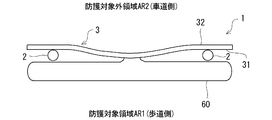
図8および図9は、実施形態1において、防護対象領域AR1(歩道)に展開した後のエアバッグ袋体60を概略的に示す図である。図8は、ガードレール1を上側から眺めた状態、図9は、ガードレール1を側面側から眺めた状態を概略的に示している。
本実施形態におけるガードレール1は、車両等といった衝突物が衝突した場合等、大きな外力がガードレール1に作用したときにエアバッグ装置4(ガス発生器50)を作動し、防護対象領域AR1(歩道)にエアバッグ袋体60を展開させることができる。これにより、防護対象領域AR1(歩道)における歩行者等といった保護対象を好適に保護することができる。つまり、ガードレール1によれば、防護対象領域AR1(歩道)の安全性をより一層確保することができる。
また、本実施形態におけるガードレール1によれば、通常時(エアバッグ装置4の作動前)は、外殻ケース41の内部にエアバッグ袋体60が折り畳まれた状態でコンパクトに収容されているため、ガードレール1が嵩張り難くすることができる。よって、歩行者の通行を妨げ難い。また、上記のように、通常時(エアバッグ装置4の作動前)は、外殻ケース41の内部にエアバッグ袋体60が収容されているため、エアバッグ袋体60が長期に亘って紫外線、雨風等に晒されることを抑制できる。従って、ガードレール1を長期に亘って使用に供した場合においても、エアバッグ袋体60が劣化することを抑制できる。これにより、長期に亘って防護性能が低下しないガードレール1を提供することができる。
更に、本実施形態におけるガードレール1は、ガス発生器50から供給するガスを用いてエアバッグ袋体60を膨張、展開させる方式であるため、ガードレール1の重量が過度に増加することを抑制できる。従って、ビーム3を支柱2に取り付ける取り付け構造が大掛かりになったり、強度を高める必要が無く、材料コストが過度に嵩み難い。以上より、本実施形態におけるガードレール1によれば、従来に比べて防護対象領域AR1の安全性をより一層確保することができ、しかも、ガードレール1が過度に嵩張ったり重量の過度な増加を伴うことなく、長期に亘って防護性能が低下しない、地面に固定される防護体を提供できる。
また、図9に示したように、エアバッグ袋体60は、展開後における高さ方向への展開幅(高さ寸法)Haが、防護隔壁部材としてのビーム3の高さ寸法Hbよりも大きくなるように設計されている。このようなエアバッグ袋体60によれば、展開後において、ビーム3の高さ方向における全体をエアバッグ袋体60によって覆うことができる。よって、防護対象領域AR1(歩道)における歩行者をより一層安全に防護することができる。
また、図3に示したように、本実施形態におけるエアバッグ装置4は、外殻ケース41(収容部40)に収容されたガス発生器50が、カバー部材417と対向しない位置に配置されている。このように、外殻ケース41を形成する壁体に比べて強度の低いカバー部材417にガス発生器50が対向しないように配置することで、ガードレール1に車両等が激しく衝突した際に、ガス発生器50のハウジング(本実施形態では、充填ボトル51)が万が一損傷した場合等においても、周囲の安全をより一層好適に確保できる。
また、本実施形態におけるガードレール1においては、エアバッグ袋体60が、外殻ケース41のカバー部材417に対向するように収容部40に配置されているため、収容部40内でエアバッグ袋体60が膨張する過程において、エアバッグ袋体60の膨張圧をカバー部材417に作用させやすく、外殻ケース41のバッグ出口416を円滑に開放することができる。
本実施形態におけるガードレール1のエアバッグ装置4は、車両等の衝突物がガードレール1に衝突した際の外力によって外殻ケース41が変形した際、当該外殻ケース41を変形させる外力を利用してガス発生器50を機械的機構によって作動させる作動機構70を備えている。これによれば、ガス発生器50を作動させるための電源を確保する必要が無い。従って、本実施形態におけるエアバッグ装置4は、電源を確保することが容易ではない、地面に固定される防護体に設置するエアバッグ装置として特に適している。また、本実施形態におけるエアバッグ装置4によれば、ガードレール1への衝突物の衝突を検知するセンサも不要である。そして、本実施形態におけるエアバッグ装置4およびその作動方法によれば、電力を使用することなく作動し、エアバッグ袋体60を膨張、展開させることができるため、設置場所についての制約を受けることなくガードレール1を設置することができる。つまり、本実施形態におけるエアバッグ装置4を適用することで、設置場所についての自由度が非常に優れたガードレール1を提供できる。
更に、本実施形態におけるエアバッグ装置4においては、外殻ケース41(外殻部)における固定具76の配置位置と起動片72(起動部)の初期位置P1は、ビーム3(防護隔壁部材)の延設方向に沿った異なる位置にそれぞれ設定されており、作動ワイヤ73(伝達部材)をビーム3(防護隔壁部材)の延設方向に沿って延設するようにした。これによれば、ビーム3に対する車両の衝突に伴って外殻ケース41が変形する際、作動ワイヤ73に張力が生じ易くなる。その結果、ビーム3に対する車両の衝突時に、起動片72を初期位置P1から起動位置P2に円滑に変位させ、エアバッグ装置4(ガス発生器50)を精度良く作動させることができる。
また、本実施形態におけるエアバッグ装置4は、図7で説明したように、作動機構70がガス発生器50を作動させる際、作動ワイヤ73の第1端部731に設けられたシール部材75が抜け止めとなって底壁部522における挿通孔522Aを塞ぐように構成されている。これにより、充填ボトル51からディフューザ室523に排出された加圧ガスが、挿通孔522Aから漏れ出すことを抑制できる。その際、ディフューザ部52における挿通孔522Aに位置付けられたシール部材75は、充填ボトル51からディフューザ室523へと加圧ガスが供給されている間に亘って、加圧ガスの圧力によって底壁部522に押し付けられる。そのため、シール部材75によって挿通孔522Aをより一層確実に閉塞し、加圧ガスの漏出を抑制できる。従って、ガス発生器50(充填ボトル51)からエアバッグ袋体60に迅速に加圧ガスを供給し、エアバッグ袋体60を膨張させることができる。また、ガス発生器50(充填ボトル51)からエアバッグ袋体60に供給される加圧ガスの量が減ってしまうことを抑制できる。
また、本実施形態におけるエアバッグ装置4は、上記のように排出パイプ524におけるガス排出口524Aとエアバッグ袋体60におけるガス導入口61が可撓性を有する連結管54によって連結されている。そのため、車両等がガードレール1に衝突した際、外殻ケース41が大きく変形しても、ガス発生器50側からエアバッグ袋体60に供給される加圧ガスの流路が閉塞したり、過度に狭まってしまうことを好適に抑制できる。但し、連結管54は、必ずしも可撓性を有している必要は無い。例えば、ディフューザ部52における排出パイプ524とエアバッグ袋体60におけるガス導入口61との間に連結管54を介在させず、エアバッグ袋体60におけるガス導入口61に対して排出パイプ524を直接的に接続しても良い。
また、本実施形態におけるエアバッグ装置4の作動機構70において、プーリ74は、作動ワイヤ73に張力を作用させるテンションプーリ(テンショナ)であっても良い。作動機構70が、テンショナとして機能するプーリ74を備えることによって、作動ワイヤ73が撓むことを抑制できる。その結果、車両等がガードレール1に衝突した際、作動ワイヤ73に張力が生じ易くなり、エアバッグ装置4(ガス発生器50)を精度良く作動させることができる。なお、プーリ74をテンションプーリとする場合、車両等がガードレール1に衝突する前の初期状態のときにプーリ74(テンショナ)が作動ワイヤ73に作用させる張力(初期張力)の大きさは、ディフューザ室523に配置された起動片72が初期位置P1から起動位置P2に変位するときに作動ワイヤ73に作用する作動時張力に比べて小さく設定される。これにより、車両等がガードレール1に衝突する前に、エアバッグ装置4(ガス発生器50)が誤って作動することを抑制できる。なお、初期状態において、作動ワイヤ73に張力を作用させるテンショナを、プーリ74とは別に配置しても良いのは勿論である。
なお、本実施形態におけるエアバッグ装置4を備えたガードレール1において、エアバッグ袋体60の展開態様、例えば、展開後におけるエアバッグ袋体60の形状、位置、大きさ等の態様は特に限定されない。また、ガードレール1におけるエアバッグ装置4の設置箇所、設置数等は特に限定されない。また、本実施形態においては、作動機構70における伝達部材として、線材である作動ワイヤ73を用いているがこれには限定されない。例えば、作動ワイヤ73の代わりに帯材を用いて、外殻ケース41に作用した外力を当該外殻ケース41に設けられた固定具76から起動片72に伝達しても良く、当該伝達機能を発揮する限りにおいて種々の形態を採用することができる。
また、上記実施形態においては、ガス発生器50における充填ボトル51のガス排出口512を封止する閉塞部材513のバースト圧を加圧ガスの充填圧よりも小さい値に設定し、車両等がガードレールに衝突する前の初期状態のときには閉塞部材513を起動片72によって直接的に支持することで閉塞部材513の開裂を抑制していたが、この態様には限定されない。例えば、作動機構70における起動片72が初期状態において配置される初期位置P1は、閉塞部材513と離間していても良い。この場合、初期状態において、閉塞部材513が加圧ガスの充填圧によって開裂しないように、閉塞部材513のバースト圧を加圧ガスの充填圧よりも大きくしておく。そして、このような態様では、車両等がガードレールに衝突した際、作動ワイヤ73を介して伝達される張力によって起動片72が初期位置P1から起動位置P2に変位した際、起動片72の変位と連動して閉塞部材513を開裂させる開封機構を別途、作動機構70が有していると良い。
上記のような開封機構としては、例えば、起爆薬を内部に収容する雷管と、雷管に衝突するようにスプリング等によって付勢された撃針(トリガー)を含み、初期状態においては起動片72を開封機構の撃針に係合させておき、撃針が雷管に向かって衝突することをスプリングの付勢力に抗して規制しておいても良い。例えば、雷管のチャンバーに収容される起爆薬は、圧力が加わると燃焼する火薬である。
このような開封機構では、スプリングの付勢力によって撃針が雷管に勢いよく衝突することで、雷管の起爆薬が燃焼し、起爆薬の燃焼によって生成された火炎や燃焼ガスの熱エネルギーによって閉塞部材513を開裂することができる。また、開封機構は、雷管の起爆薬とは別の伝火薬を収容する伝火薬チャンバーを有し、雷管のチャンバーと伝火薬チャンバーとを伝火孔(フラッシュホール)によって連通させておいても良い。この場合、雷管における起爆薬の燃焼によって生成された火炎や燃焼ガスを火薬チャンバー内に伝火孔を通じて導入させ、その熱エネルギーによって伝火薬に着火しても良い。そして、伝火薬の燃焼によって生成された火炎や燃焼ガスの熱エネルギーによって閉塞部材513を開裂しても良い。
上記開封機構では、車両等がガードレールに衝突する前の初期状態において起動片72が初期位置P1に配置されている限りにおいては、撃針が雷管に衝突することが規制される。その結果、充填ボトル51のガス排出口512は、閉塞部材513によって封止された状態に維持される。一方、車両等がガードレールに衝突し、作動ワイヤ73によって起動片72が初期位置P1から起動位置P2に変位すると、起動片72と撃針との係合が解除される。その結果、スプリングの付勢力によって撃針が雷管に勢いよく衝突することで雷管の起爆薬が着火し、閉塞部材513が開裂する。これにより、充填ボトル51のガス排出口512が開封し、ガス発生器50を作動させることがきる。
また、上記開封機構の別態様として、例えば、車両等がガードレールに衝突したときに、先端が尖ったロッド部材や矢じり部材等によって形成された開裂用部材をスプリング等の付勢力を利用して閉塞部材513に衝突させ、その衝撃によって直接的に閉塞部材513を開裂する態様を採用しても良い。この場合、車両等がガードレールに衝突する前の初期状態においては、例えば起動部として構成されたストッパー部材を開裂用部材と係合させておき、開裂用部材が閉塞部材513に向かって発射されることをスプリングの付勢力に抗して規制しておいても良い。また、ストッパー部材(起動部)は作動ワイヤ73の第1端部731に接続されており、車両等がガードレールに衝突した際に作動ワイヤ73に引っ張られることによってストッパー部材(起動部)が開裂用部材と係合する初期位置P1から、その係合状態を解除する起動位置P2へと変位する。これを契機として、開裂用部材がスプリングの付勢力によって閉塞部材513に向かって発射され、閉塞部材513に開裂用部材が勢いよく衝突することによって閉塞部材513を開裂させ、充填ボトル51のガス排出口512を開封しても良い。
<実施形態2>
次に、実施形態2に係るエアバッグ装置を備えた防護体としてのガードレール1Aを説明する。図10は、実施形態2に係るガードレール1Aの斜視図である。図10は、ガードレール1Aを背面側から眺めた状態を示しており、実施形態1と共通の構成については同一の参照符号を付すことで詳しい説明を省略する。
次に、実施形態2に係るエアバッグ装置を備えた防護体としてのガードレール1Aを説明する。図10は、実施形態2に係るガードレール1Aの斜視図である。図10は、ガードレール1Aを背面側から眺めた状態を示しており、実施形態1と共通の構成については同一の参照符号を付すことで詳しい説明を省略する。
本実施形態におけるガードレール1Aにおいても、実施形態1に係るガードレール1と同様、ビーム3が支柱2によって支持されている。また、支柱2は、当該支柱2が防護対象領域AR1に配置されるようにビーム3の防護内面31に接合されている。また、本実施形態におけるガードレール1Aは、エアバッグ装置4Aがビーム3ではなく、支柱2に設けられている。支柱2は、内部が中空構造となっており、エアバッグ装置4Aの各種部品を収容する収容部40が支柱2の内部に形成されている。図10に示す符号20は、支柱2における円筒壁であり、円筒壁20の内側に収容部40が形成されている。本実施形態においては、内側に収容部40が形成される円筒壁20が外殻部の一例である。また、支柱2における円筒壁20のうち、防護対象領域AR1に面する位置には、バッグ出口416が開口形成されており、当該バッグ出口416がカバー部材417によって遮蔽されている。
また、図10に示すように、ガードレール1Aは、太陽光発電ユニット85を備えている。太陽光発電ユニット85は、太陽光エネルギーによって発電する太陽光発電パネルが上面に配置されており、ポール状の支持ポール86の上端に支持された状態で、ガードレール1Aに取り付けられている。支持ポール86は、例えば、支柱2にビーム3を取り付ける取付具5に取り付けられていても良い。太陽光発電ユニット85によって発電された電力は、支柱2に設けられたエアバッグ装置4Aを作動するために用いられる。そのため、太陽光発電ユニット85を支持する支持ポール86は、エアバッグ装置4Aを収容する支柱2の近傍に設置されている。
図11は、実施形態2に係るガードレール1Aにおける支柱2の内部構造を説明する図である。円筒壁20の内側に形成される収容部40には、ガス発生器50A、エアバッグ袋体60、制御ユニット80、電源81、衝突検知センサ82等が収容されている。ガス発生器50A、エアバッグ袋体60、制御ユニット80、電源81、衝突検知センサ82は、円筒壁20の内壁面に設けられた適宜の固定部材(図示せず)によって、収容部40における所定位置に固定されている。
ここで、ガス発生器50Aの種類は特に限定されない。ここでは、固体のガス発生剤を用いるパイロ方式インフレータをガス発生器50Aに適用する場合を例に説明する。ガス発生器50Aは、図示しない電気式点火器を有し、電気式点火器を作動させることによってガス発生剤に着火し、発生したガスをクーラントで冷却した後、ハウジングに形成されたガス排出口512Aから噴出させる。勿論、ガス発生器50Aは、実施形態1と同様、加圧ガスが充填された充填ボトル51を有するストアードガス方式のガス発生器であっても良い。
エアバッグ袋体60は、収容部40内において折り畳まれた状態でガス発生器50Aの近傍に配置されている。そして、ガス発生器50Aの作動時においては、ガス発生器50Aのガス排出口512Aから噴出するガスがエアバッグ袋体60に供給されることによって膨張する。また、図11に示すように、エアバッグ袋体60は、支柱2における円筒壁20に形成されたバッグ出口416およびカバー部材417に対向する位置に配置されている。
制御ユニット80は、ガス発生器50Aを制御するためのコントロールユニットであり、ガス発生器50Aの電気式点火器、電源81、衝突検知センサ82とリード線等を介して接続されている。衝突検知センサ82は、ガードレール1Aに対して車両等の衝突物が衝突したことを検知するためのセンサであり、公知のエアバッグ用センサを適用することができる。また、電源81は、例えば二次電池(蓄電池)である。電源81は、リード線によって太陽光発電ユニット85と接続されており、太陽光発電ユニット85によって発電された電力を蓄電する。
また、制御ユニット80は、衝突検知センサ82から入力される信号に基づいて、衝突検知センサ82が検知した衝突レベルを判定するためのマイコン等を有している。制御ユニット80は、衝突検知センサ82から受信した信号に基づいて衝突レベルを判定し、エアバッグ袋体60を膨らませる必要があると判断すると、ガス発生器50Aの電気式点火器に作動信号を送り、電気式点火器を作動させる。例えば、制御ユニット80は、衝突検知センサ82から受信した衝撃レベルが判定用の基準衝撃レベルよりも大きい場合に、ガードレール1Aに車両が衝突したと判断し、ガス発生器50Aを作動させても良い。その際、制御ユニット80は、例えば、ガードレール1Aを人が蹴った程度では作動しないように、上記判定用の基準衝撃レベルを設定しておくと良い。制御ユニット80からの作動信号に基づいてガス発生器50Aが作動すると、ガス発生器50Aにおいて生成されたガスがガス排出口512Aから噴出され、当該ガスがエアバッグ袋体60に供給される。なお、衝突検知センサ82は、制御ユニット80に実装されていても良い。
ガス発生器50Aからエアバッグ袋体60に対するガスの供給が開始されると、まず、収容部40内でエアバッグ袋体60が膨張する。そして、収容部40内でエアバッグ袋体60が膨張する過程において、支柱2における円筒壁20のバッグ出口416を遮蔽するカバー部材417にエアバッグ袋体60の膨張圧が作用する。円筒壁20からカバー部材417が外れ、或いは、破壊されることにより、バッグ出口416が開放される。これにより、エアバッグ袋体60をバッグ出口416から円筒壁20(収容部40)の外部に展開させることができる。そして、支柱2における円筒壁20のバッグ出口416は、防護対象領域AR1(歩道)に面しているため、エアバッグ袋体60を防護対象領域AR1(歩道)に展開させることができる。
図12は、実施形態2に係るガードレール1Aにおいて、防護対象領域AR1(歩道)に展開した後のエアバッグ袋体60を概略的に示す図である。図12は、ガードレール1を上側から眺めた状態を示している。また、図12においては便宜上、太陽光発電ユニット85および支持ポール86の図示を省略している。
図12に示すように、本実施形態におけるガードレール1Aにおいても、ガードレール1Aに対して車両等の衝突物が衝突した場合、エアバッグ装置4A(ガス発生器50A)が作動し、防護対象領域AR1(歩道)にエアバッグ袋体60が展開する。これにより、防護対象領域AR1(歩道)における歩行者を好適に防護することができ、当該防護対象領域AR1の安全性をより一層確保することができる。
なお、本実施形態におけるエアバッグ装置4Aにおいて、電源81を二次電池(蓄電池)とし、太陽光発電ユニット85が発電した電力をエアバッグ装置4Aの作動電源として利用する例を説明したが、これには限定されない。例えば、外部電源からエアバッグ装置4Aに電力を供給しても良い。また、本実施形態において、ビーム3の防護内面31に支柱2が接合されることで、支柱2が防護対象領域AR1に配置されている。このように支柱2を配置することで、エアバッグ装置4Aの作動時に支柱2の内部に形成された収容部40からエアバッグ袋体60を防護対象領域AR1に展開させ易いという利点がある。
また、本実施形態におけるガードレール1Aは、ビーム3を支持する支柱2の円筒壁20を外殻部として構成し、当該円筒壁20の内部に形成された収容部40にガス発生器50Aやエアバッグ袋体60等を収容したが、これには限られない。例えば、実施形態1に係るような外殻ケース41を支柱2の外側に付設し、ガードレール1Aに車両が衝突した際に防護対象領域AR1(歩道)にエアバッグ袋体60を展開しても良い。
<変形例>
次に、実施形態2における変形例を説明する。図13および図14は、実施形態2の変形例に係るエアバッグ袋体60Aを説明する図である。図13は、ガードレール1Aの背面側から変形例に係る展開後のエアバッグ袋体60Aを眺めた状態、図14は、ガードレール1Aの上方から変形例に係る展開後のエアバッグ袋体60Aを眺めた状態を概略的に示している。なお、図13、図14においても、太陽光発電ユニット85および支持ポール86の図示を省略している。
次に、実施形態2における変形例を説明する。図13および図14は、実施形態2の変形例に係るエアバッグ袋体60Aを説明する図である。図13は、ガードレール1Aの背面側から変形例に係る展開後のエアバッグ袋体60Aを眺めた状態、図14は、ガードレール1Aの上方から変形例に係る展開後のエアバッグ袋体60Aを眺めた状態を概略的に示している。なお、図13、図14においても、太陽光発電ユニット85および支持ポール86の図示を省略している。
図13、図14に示すエアバッグ袋体60Aは、ガス発生器50Aの作動時に当該ガス発生器50Aから供給されるガスが導入される導入部62、導入部62と連通する腕部63、腕部63と複数箇所で連通する複数の支持部64、エアバッグ袋体60Aの外面に取り付けられた緩衝材65等を含んでいる。腕部63は、導入部62から供給されるガスによって展開する際に防護隔壁部材としてのビーム3の延設方向に沿って延びる部位である。また、支持部64は、腕部63から供給されるガスによって展開する際に当該腕部63の延設方向と交差する方向に延びる部位である。
図13、図14に示す例では、腕部63の両端部63A,63Bおよび中央部63Cから3本の支持部64が上方に向かって伸びている。ここで、腕部63の中央部63Cから上方に延在する支持部64を中央支持部64Aと呼ぶ。そして、腕部63の端部63Aから上方に延在する支持部64を第1支持部64Bと呼び、腕部63の端部63Bから上方に延在する支持部64を第2支持部64Cと呼ぶ。また、腕部63のうち、端部63Aから中央部63Cまでの領域を第1腕領域631と呼び、端部63Bから中央部63Cまでの領域を第2腕領域632と呼ぶ。エアバッグ袋体60Aの導入部62、腕部63、および各支持部64は連通しており、ガス発生器50Aから供給されるガスは、エアバッグ袋体60Aの内部へ導入部62から流入し、導入部62から腕部63、支持部64に順次供給される。その結果、図13および図14に示すように、エアバッグ袋体60Aにおける導入部62、腕部63、および支持部64が膨張し、防護対象領域AR1(歩道)に展開する。
更に、本変形例に係るエアバッグ袋体60Aは、その外面に緩衝材65が取り付けられている。そして、エアバッグ袋体60Aが展開する際に、各支持部64および腕部63で囲まれた領域に緩衝材65が張架されるようになっている。緩衝材65の材料は特に限定されないが、適度な柔軟性と耐久性を有する布材料や網(ネット)材料によって形成することが好ましい。例えば、緩衝材65は、支持部64や腕部63等を形成するエアバッグ用生地(基布)と同一素材によって形成されていても良い。なお、エアバッグ袋体60Aの外面に取り付けられている緩衝材65は、ガスが導入されない構造となっている。
本変形例に係るエアバッグ袋体60Aを備えたエアバッグ装置4Aは、導入部62、腕部63、および支持部64だけでなく、各支持部64および腕部63で囲まれた領域に張架された緩衝材65によって防護対象領域AR1(歩道)における歩行者等を保護することができる。エアバッグ袋体60Aは、展開後に緩衝材65が張架される領域にガスを導入する必要がないため、ガス発生器50Aからエアバッグ袋体60Aに多量のガスを供給することなく、エアバッグ袋体60Aによって保護可能な領域を十分に確保することができる。そのため、エアバッグ袋体60Aの小型化が可能となる。また、エアバッグ袋体60Aにガスを供給するガス発生器50Aの小型化も可能となる。
また、図14に示すように、本変形例に係るエアバッグ袋体60Aは、展開後において、腕部63が上面視V字形状となるように構成されており、展開後における腕部63が支柱2やビーム3に対して離間するようになっている。すなわち、上面視において、中央支持部64Aを基準として、腕部63における第1腕領域631と第2腕領域632とが180°よりも小さな角度をなすように接続されている。これにより、エアバッグ袋体60Aにおける緩衝材65を、ガードレール1Aにおける支柱2およびビーム3に対して離れた位置に張架させることができる。すなわち、防護対象領域AR1(歩道)に展開させたエアバッグ袋体60Aにおける緩衝材65とビーム3との間に緩衝空間Asを形成することができる。
その結果、車両等がガードレール1Aに衝突した際、緩衝材65によって歩行者を捕捉した際、緩衝材65とビーム3との間に緩衝空間Asを形成しておくことで、歩行者をより一層安全に防護することができる。なお、図14に示す符号D1は、腕部63における第1腕領域631と第2腕領域632とによって形成される角度(以下、「腕部角度」という)である。腕部角度D1は、150°以下の範囲で設定しても良く、このようにすることで展開後におけるエアバッグ袋体60Aの緩衝材65とビーム3との間に緩衝空間Asを十分に確保することができる。
<他の実施形態>
上述までの実施形態および変形例においては、本開示に係る防護体を、道路に沿って設置されるガードレールに適用する場合を例に説明したが、ガードレール以外の防護体に適用しても良い。すなわち、本開示に係る防護体は、地面に固定され、空間を防護対象領域と防護対象外領域とに仕切るための種々のフェンス、防護柵等に適用することができる。また、防護体によって仕切られる防護対象領域と防護対象外領域は、歩道と車道に限定されないのは勿論である。例えば、防護体は、工場や倉庫等といった施設内において、フォークリフト等による作業が行われる作業エリアと、作業外エリアの境界部に沿って設置されるフェンス、防護柵等であっても良い。
上述までの実施形態および変形例においては、本開示に係る防護体を、道路に沿って設置されるガードレールに適用する場合を例に説明したが、ガードレール以外の防護体に適用しても良い。すなわち、本開示に係る防護体は、地面に固定され、空間を防護対象領域と防護対象外領域とに仕切るための種々のフェンス、防護柵等に適用することができる。また、防護体によって仕切られる防護対象領域と防護対象外領域は、歩道と車道に限定されないのは勿論である。例えば、防護体は、工場や倉庫等といった施設内において、フォークリフト等による作業が行われる作業エリアと、作業外エリアの境界部に沿って設置されるフェンス、防護柵等であっても良い。
図15および図16は、他の実施形態に係る防護体1Bを説明する図である。図15は、防護体1Bの背面図、図16は、防護体1Bの上面図である。上述までの実施形態に係るガードレールと同一の構成については同一の符号を付すことで詳しいです明を省略する。
防護体1Bは、防護対象領域AR1と防護対象外領域AR2との境界部に沿って延設される防護隔壁部材3Bと、防護隔壁部材3Bを支持する複数の支柱2Bを有している。防護隔壁部材3Bは、防護対象領域AR1と防護対象外領域AR2との境界部に沿って延びる複数の横桟部材300を含んでおり、各横桟部材300は例えば一定の間隔をおいて上下に並んで配置されている。なお、各横桟部材300は、防護対象領域AR1に面する防護内面31と、防護対象外領域AR2に面する防護外面32を有している。防護体1Bは、例えば、工場や倉庫等の施設における床面(地面)に固定される防護柵である。そして、防護体1Bは、フォークリフト等による作業が行われる作業エリアと、従業員等が通行する通行エリアの境界位置に沿って設置される。
防護体1Bは、エアバッグ装置4Bを備えており、防護隔壁部材3Bにおける防護内面31にエアバッグ装置4Bの外殻ケース41が取り付けられている。外殻ケース41の内部構造は、実施形態1の図3、図4等で説明した構造と同一であっても良いし、実施形態2の図11等で説明した構造と同一であっても良い。このような防護体1Bにおいても、防護体1Bに衝突物が衝突した際、外殻ケース41内に収容されているエアバッグ袋体にガス発生器からガスを供給し、当該エアバッグ袋体を防護対象領域AR1に展開させることにより、防護対象領域AR1における人を安全に防護することができる。
なお、図15および図16に示す例では、防護体1Bにおける防護隔壁部材3Bに外殻ケース41を取り付ける態様を例に説明したが、これには限定されない。例えば、防護体1Bにおける防護隔壁部材3Bを中空構造とし、エアバッグ装置4Bを構成するエアバッグ袋体やガス発生器等を収容する収容部を防護隔壁部材3Bの内部に形成しても良い。また、防護体1Bにおける防護隔壁部材3Bに外殻ケース41を配設する代わりに、支柱2Bに外殻ケース41を配設しても良い。
本明細書に開示された各々の態様は、本明細書に開示された他のいかなる特徴とも組み合わせることができる。
1・・・ガードレール
2・・・支柱
3・・・ビーム
4・・・エアバッグ装置
40・・・収容部
41・・・外殻ケース
50・・・ガス発生器
51・・・充填ボトル
52・・・ディフューザ部
60・・・エアバッグ袋体
70・・・作動機構
71・・・支持体
72・・・起動片
73・・・作動ワイヤ
74・・・プーリ
75・・・シール部材
76・・・固定具
2・・・支柱
3・・・ビーム
4・・・エアバッグ装置
40・・・収容部
41・・・外殻ケース
50・・・ガス発生器
51・・・充填ボトル
52・・・ディフューザ部
60・・・エアバッグ袋体
70・・・作動機構
71・・・支持体
72・・・起動片
73・・・作動ワイヤ
74・・・プーリ
75・・・シール部材
76・・・固定具
Claims (10)
- 地面に固定され、空間を防護対象領域と防護対象外領域とに仕切るための防護体であって、
ガス発生器と、
前記ガス発生器の作動時に当該ガス発生器から供給されるガスによって膨張することで前記防護対象領域に展開するエアバッグ袋体と、
前記ガス発生器および前記エアバッグ袋体を収容する外殻部と、
を備える、防護体。 - 前記外殻部は、前記ガス発生器の作動時に前記エアバッグ袋体を外部に展開させるためのバッグ出口を有し、前記バッグ出口が前記防護対象領域に面するように設けられている、
請求項1に記載の防護体。 - 前記防護対象領域と前記防護対象外領域との境界部に沿って延設され、前記防護対象領域に面する防護内面と、前記防護対象外領域に面する防護外面と、を有する防護隔壁部材を含み、
前記外殻部が前記防護隔壁部材に設けられている、
請求項2に記載の防護体。 - 前記防護対象領域と前記防護対象外領域との境界部に沿って延設され、前記防護対象領域に面する防護内面と、前記防護対象外領域に面する防護外面と、を有する防護隔壁部材と、
前記防護隔壁部材を支持する支柱と、を含み、
前記外殻部が前記支柱に設けられている、
請求項2に記載の防護体。 - 前記支柱は、当該支柱が前記防護対象領域に配置されるように前記防護隔壁部材の前記防護内面に接合されている、
請求項4に記載の防護体。 - 前記エアバッグ袋体は、展開後における高さ方向への展開幅が、前記防護隔壁部材の高さ寸法よりも大きい、
請求項3から5の何れか一項に記載の防護体。 - 前記外殻部は、前記バッグ出口を遮蔽するカバー部材を有し、前記ガス発生器の作動時に前記エアバッグ袋体の膨張圧によって前記バッグ出口が開放される、
請求項2から6の何れか一項に記載の防護体。 - 前記カバー部材は、前記外殻部に比べて低強度であり、
前記ガス発生器は、前記外殻部において前記カバー部材と対向しない位置に配置されている、
請求項7に記載の防護体。 - 前記エアバッグ袋体は、
前記ガス発生器の作動時に当該ガス発生器から供給されるガスが導入される導入部と、
前記導入部と連通し、前記導入部から供給されるガスによって展開する際に前記防護隔壁部材の延設方向に沿って延びる腕部と、
前記腕部と複数箇所で連通し、前記腕部から供給されるガスによって展開する際に前記腕部の延設方向と交差する方向に延びる複数の支持部と、
前記エアバッグ袋体の外面に取り付けられ、前記エアバッグ袋体が展開する際に前記複数の支持部および前記腕部で囲まれた領域に張架される緩衝材と、
を有する、
請求項3から6の何れか一項に記載の防護体。 - 前記防護体は、歩道と車道との境界位置に設置されるガードレールである、請求項1から9の何れか一項に記載の防護体。
Priority Applications (2)
| Application Number | Priority Date | Filing Date | Title |
|---|---|---|---|
| DE112020006390.9T DE112020006390T5 (de) | 2019-12-26 | 2020-07-02 | Schutzkörper |
| CN202080090371.7A CN114867916A (zh) | 2019-12-26 | 2020-07-02 | 防护体 |
Applications Claiming Priority (2)
| Application Number | Priority Date | Filing Date | Title |
|---|---|---|---|
| JP2019237245A JP7313276B2 (ja) | 2019-12-26 | 2019-12-26 | 防護体 |
| JP2019-237245 | 2019-12-26 |
Publications (1)
| Publication Number | Publication Date |
|---|---|
| WO2021131111A1 true WO2021131111A1 (ja) | 2021-07-01 |
Family
ID=76575729
Family Applications (1)
| Application Number | Title | Priority Date | Filing Date |
|---|---|---|---|
| PCT/JP2020/026090 Ceased WO2021131111A1 (ja) | 2019-12-26 | 2020-07-02 | 防護体 |
Country Status (4)
| Country | Link |
|---|---|
| JP (1) | JP7313276B2 (ja) |
| CN (1) | CN114867916A (ja) |
| DE (1) | DE112020006390T5 (ja) |
| WO (1) | WO2021131111A1 (ja) |
Families Citing this family (2)
| Publication number | Priority date | Publication date | Assignee | Title |
|---|---|---|---|---|
| KR102445613B1 (ko) * | 2022-02-21 | 2022-09-21 | 애프터레인 주식회사 | 보차도 경계용 플랜트 박스 유닛 |
| DE102024102745B4 (de) * | 2024-01-31 | 2025-10-02 | Dr. Ing. H.C. F. Porsche Aktiengesellschaft | Verwendung einer Querungsanlage |
Citations (6)
| Publication number | Priority date | Publication date | Assignee | Title |
|---|---|---|---|---|
| JPS6367304A (ja) * | 1986-09-09 | 1988-03-26 | 桐生 三男 | 地吹雪防護装置 |
| JPH10219640A (ja) * | 1997-01-31 | 1998-08-18 | Toray Ind Inc | バリケード |
| JPH10281200A (ja) * | 1997-04-07 | 1998-10-20 | Fujikura Kousou Kk | 衝撃吸収エアバック |
| JP2003064626A (ja) * | 2001-08-29 | 2003-03-05 | Yutaka Hirano | エアバック式警戒表示器材 |
| JP2009034469A (ja) * | 2007-08-02 | 2009-02-19 | Toyo Autom Kk | 地震時における災害防止装置およびその装具 |
| US20100003078A1 (en) * | 2008-07-07 | 2010-01-07 | National Taipei University Of Technology | Anti-terror car-attack defending apparatus |
Family Cites Families (6)
| Publication number | Priority date | Publication date | Assignee | Title |
|---|---|---|---|---|
| CA2182542A1 (en) | 1996-08-01 | 1998-02-02 | Koichi Yoshino | Shock absorbing wall construction |
| JP2011241571A (ja) | 2010-05-17 | 2011-12-01 | Kimio Otake | ガードレール |
| CN206328711U (zh) * | 2016-12-21 | 2017-07-14 | 张贺宇 | 一种基于技术服务的高速公路应急车道安全防护装置 |
| CN109898445A (zh) * | 2017-12-07 | 2019-06-18 | 西安佳纳环保科技有限公司 | 一种桥梁用保护性强的市政护栏 |
| CN208586553U (zh) * | 2018-05-21 | 2019-03-08 | 大唐水电科学技术研究院有限公司 | 一种用于保护机电设备的防水隔离装置 |
| CN110080136B (zh) * | 2019-04-26 | 2023-07-25 | 南京航空航天大学 | 一种车辆侧翻智能防护系统及其控制方法 |
-
2019
- 2019-12-26 JP JP2019237245A patent/JP7313276B2/ja active Active
-
2020
- 2020-07-02 CN CN202080090371.7A patent/CN114867916A/zh active Pending
- 2020-07-02 WO PCT/JP2020/026090 patent/WO2021131111A1/ja not_active Ceased
- 2020-07-02 DE DE112020006390.9T patent/DE112020006390T5/de active Pending
Patent Citations (6)
| Publication number | Priority date | Publication date | Assignee | Title |
|---|---|---|---|---|
| JPS6367304A (ja) * | 1986-09-09 | 1988-03-26 | 桐生 三男 | 地吹雪防護装置 |
| JPH10219640A (ja) * | 1997-01-31 | 1998-08-18 | Toray Ind Inc | バリケード |
| JPH10281200A (ja) * | 1997-04-07 | 1998-10-20 | Fujikura Kousou Kk | 衝撃吸収エアバック |
| JP2003064626A (ja) * | 2001-08-29 | 2003-03-05 | Yutaka Hirano | エアバック式警戒表示器材 |
| JP2009034469A (ja) * | 2007-08-02 | 2009-02-19 | Toyo Autom Kk | 地震時における災害防止装置およびその装具 |
| US20100003078A1 (en) * | 2008-07-07 | 2010-01-07 | National Taipei University Of Technology | Anti-terror car-attack defending apparatus |
Also Published As
| Publication number | Publication date |
|---|---|
| JP7313276B2 (ja) | 2023-07-24 |
| JP2021105297A (ja) | 2021-07-26 |
| CN114867916A (zh) | 2022-08-05 |
| DE112020006390T5 (de) | 2023-01-19 |
Similar Documents
| Publication | Publication Date | Title |
|---|---|---|
| US6428041B1 (en) | Airbag system for a motor vehicle | |
| EP0812740B1 (en) | Directional compressed gas inflator | |
| CN110576823B (zh) | 安全气囊装置 | |
| JP5983663B2 (ja) | 歩行者保護エアバッグ装置 | |
| US7328914B2 (en) | Inflator | |
| US7246819B2 (en) | Airbag module and method of restraining a vehicle occupant with such an airbag module | |
| WO2021131111A1 (ja) | 防護体 | |
| WO2022050145A1 (ja) | 歩行者保護用エアバッグ装置 | |
| US20080238059A1 (en) | Airbag Module for Protection of a Vehicle Occupant | |
| JP2007112183A (ja) | 車外用エアバッグ装置 | |
| WO2021131107A1 (ja) | 防護体、防護体におけるエアバッグ装置、および防護体におけるエアバッグ装置の作動方法 | |
| JP2003306098A (ja) | 車両外置きエアバック装置 | |
| US20030197358A1 (en) | Air bag module assembly | |
| JP2015136978A (ja) | フード付け車両用歩行者保護エアバッグ装置の搭載構造 | |
| US7293799B2 (en) | Gas bag module | |
| CN100375691C (zh) | 充气器 | |
| JP2021105297A5 (ja) | ||
| JP5242228B2 (ja) | 人員拘束装置用ガス発生器 | |
| US20050029788A1 (en) | Inflator | |
| WO2025216214A1 (ja) | エアバッグモジュール | |
| JP4971971B2 (ja) | エアバッグ装置 | |
| KR100538511B1 (ko) | 듀얼 스테이지 에어백 모듈 | |
| JP2002362298A (ja) | ガス発生器及びそれに用いるフィルター材 | |
| WO2022018888A1 (ja) | エアバッグ装置 | |
| JP2004352072A (ja) | インフレータ |
Legal Events
| Date | Code | Title | Description |
|---|---|---|---|
| 121 | Ep: the epo has been informed by wipo that ep was designated in this application |
Ref document number: 20907075 Country of ref document: EP Kind code of ref document: A1 |
|
| 122 | Ep: pct application non-entry in european phase |
Ref document number: 20907075 Country of ref document: EP Kind code of ref document: A1 |