WO2021131049A1 - 天井埋め込み型空気調和機の室内機 - Google Patents
天井埋め込み型空気調和機の室内機 Download PDFInfo
- Publication number
- WO2021131049A1 WO2021131049A1 PCT/JP2019/051541 JP2019051541W WO2021131049A1 WO 2021131049 A1 WO2021131049 A1 WO 2021131049A1 JP 2019051541 W JP2019051541 W JP 2019051541W WO 2021131049 A1 WO2021131049 A1 WO 2021131049A1
- Authority
- WO
- WIPO (PCT)
- Prior art keywords
- hanging
- housing
- ceiling
- channel
- indoor unit
- Prior art date
- Legal status (The legal status is an assumption and is not a legal conclusion. Google has not performed a legal analysis and makes no representation as to the accuracy of the status listed.)
- Ceased
Links
Images





Classifications
-
- F—MECHANICAL ENGINEERING; LIGHTING; HEATING; WEAPONS; BLASTING
- F24—HEATING; RANGES; VENTILATING
- F24F—AIR-CONDITIONING; AIR-HUMIDIFICATION; VENTILATION; USE OF AIR CURRENTS FOR SCREENING
- F24F1/00—Room units for air-conditioning, e.g. separate or self-contained units or units receiving primary air from a central station
- F24F1/0007—Indoor units, e.g. fan coil units
- F24F1/0043—Indoor units, e.g. fan coil units characterised by mounting arrangements
- F24F1/0047—Indoor units, e.g. fan coil units characterised by mounting arrangements mounted in the ceiling or at the ceiling
-
- F—MECHANICAL ENGINEERING; LIGHTING; HEATING; WEAPONS; BLASTING
- F24—HEATING; RANGES; VENTILATING
- F24F—AIR-CONDITIONING; AIR-HUMIDIFICATION; VENTILATION; USE OF AIR CURRENTS FOR SCREENING
- F24F13/00—Details common to, or for air-conditioning, air-humidification, ventilation or use of air currents for screening
- F24F13/20—Casings or covers
Definitions
- the present disclosure relates to an indoor unit of a ceiling-embedded air conditioner, and particularly to an indoor unit of a ceiling-embedded air conditioner suspended using a channel.
- the housing of the indoor unit of the ceiling-embedded air conditioner has a substantially octagonal shape with four squares chamfered when viewed from above.
- a standard hanging bracket connected to the hanging bolt is attached to the chamfered portion.
- Such a ceiling-embedded indoor unit can be hung by passing a hanging bolt hanging from a channel in the ceiling through a mounting hole of a standard hanging bracket and fixing it with a nut or the like.
- the position of the mounting hole of the standard hanging bracket is inside the position of the outer side surface parallel to the vertical direction of the housing of the indoor unit when the housing of the indoor unit is viewed from above.
- the position of the hanging bolt hanging from the channel and the position of the part of the channel connected to the hanging bolt are set in the housing of the indoor unit. It is inside the outer side surface parallel to the vertical direction. Therefore, in the ceiling-embedded air conditioner using the conventional channel, the channel has no choice but to be arranged above the indoor unit, and the channel and the indoor unit are arranged side by side in the vertical direction.
- the present disclosure has been made in view of the above circumstances, and provides an indoor unit of a ceiling-embedded air conditioner that can be suspended in a small vertical space for mounting the indoor unit of the air conditioner on the ceiling.
- the purpose is to do.
- the indoor unit of the ceiling-embedded air conditioner according to the present disclosure is passed through a ceiling-embedded housing used for air conditioning and a hanging bolt attached to the side surface of the housing and hung from a channel.
- a first hanging bracket having a hanging bolt mounting hole is provided, and the hanging bolt mounting hole of the first hanging bracket is provided at a position outside the side surface of the housing.
- the first hanging bracket is attached to the side surface of the housing and has a hanging bolt mounting hole through which the hanging bolt is passed.
- the hanging bolt mounting hole of the first hanging bracket is provided at a position outside the side surface of the housing. Therefore, the housing of the indoor unit and the channel are arranged side by side in the horizontal direction. As a result, the indoor unit of the ceiling-embedded air conditioner can be hung in a small space in the vertical direction of the ceiling.
- FIG. 5 is a top view of the housing of the indoor unit of the ceiling-embedded air conditioner according to the first embodiment. It is a figure which shows the additional hanging metal fitting of the indoor unit of the ceiling-embedded type air conditioner which concerns on Embodiment 1.
- FIG. It is a top view of the additional hanging metal fitting of the indoor unit of the ceiling-embedded air conditioner according to the first embodiment, and the vicinity of the second channel.
- FIG. 5 is a top view of the housing of the indoor unit of the ceiling-embedded air conditioner according to the second embodiment.
- FIG. 5 is a top view of the housing of the indoor unit of the ceiling-embedded air conditioner according to the third embodiment.
- FIG. 1 is a perspective view showing an indoor unit 100 of the ceiling-embedded air conditioner according to the first embodiment.
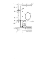
- FIG. 2 is a front view showing a suspended state of the housing 1 of the indoor unit 100 of the ceiling-embedded air conditioner according to the first embodiment.
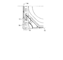
- FIG. 3 is a top view of the housing 1 of the indoor unit 100 of the ceiling-embedded air conditioner according to the first embodiment.
- the indoor unit 100 of the ceiling-embedded air conditioner has a box-shaped housing 1 having a substantially octagonal upper surface.
- a square decorative panel 2 is attached to the lower side of the housing 1 of the indoor unit 100.
- first hanging bolts 9a to 9d are vertically attached to the ceiling slab 6 by anchor bolts or the like.
- the other ends of the first hanging bolt 9a and the first hanging bolt 9c are passed through any of a plurality of bolt holes 22 provided in the first channel 5a and fixed by nuts 21 respectively.
- the other ends of the first hanging bolt 9b and the first hanging bolt 9d are passed through any of a plurality of bolt holes 22 provided in the second channel 5b and fixed by nuts 21 respectively.
- the first channel 5a and the second channel 5b are members having a substantially U-shaped cross section and having a plurality of bolt holes 22 formed in a row on the upper surface.
- the first channel 5a is arranged on the right side surface 1aa side of the housing 1 when viewed from the front of the housing 1. Specifically, the first channel 5a is arranged side by side in the horizontal direction of the housing 1. Further, the first channel 5a extends in the horizontal direction in the longitudinal direction and is arranged along the right side surface 1aa of the housing 1.
- the second channel 5b is arranged on the left side surface 1ab side of the housing 1 when viewed from the front of the housing 1. Specifically, the second channel 5b is arranged side by side in the horizontal direction of the housing 1. Further, the second channel 5b extends in the horizontal direction in the longitudinal direction and is arranged along the left side surface 1ab of the housing 1.
- the first channel 5a and the second channel 5b are arranged parallel to each other.
- One end side of the second hanging bolt 8a and the second hanging bolt 8c (not shown) is fixed vertically to the first channel 5a by the nut 21 through the bolt hole 22.
- the other ends of the second hanging bolt 8a and the second hanging bolt 8c are fixed to the additional hanging bracket 4a and the additional hanging bracket 4c, respectively.
- One end side of the second hanging bolt 8b and the second hanging bolt 8d is passed through the bolt hole 22 and fixed vertically to the second channel 5b by the nut 21.
- the other ends of the second hanging bolt 8b and the second hanging bolt 8d are fixed to the additional hanging bracket 4b and the additional hanging bracket 4d, respectively.
- standard hanging metal fittings 3a to 3d are attached to the side surfaces Ca to Cd of the four corners of the housing 1, respectively.
- a pipe take-out portion 1c is provided on the side surface Cc of the corner portion on the upper right side when viewed from the upper surface of the housing 1 when the front surface is facing down.
- the pipe take-out unit 1c is a take-out part of an inflow pipe through which the refrigerant flowing into the housing 1 of the indoor unit 100 flows and an outflow pipe through which the refrigerant flowing out from the housing 1 flows.
- an additional hanging metal fitting 4a is attached to the right side surface 1aa near the side surface Ca of the corner portion on the front side of the housing 1.
- An additional hanging bracket 4b is attached to the left side surface 1ab near the side surface Cb at the corner of the housing 1.
- An additional hanging bracket 4c is attached to the right side surface 1aa near the side surface Cc at the corner of the housing 1.
- an additional hanging metal fitting 4d is attached to the left side surface 1ab near the side surface Cd at the corner of the housing 1.
- one end side of the first hanging bolt 9a is attached to the ceiling slab 6 on the right side side when viewed from the front of the housing 1 by anchor bolts or the like.
- the other end side of the first hanging bolt 9a is fixed to the first channel 5a by the nut 21.
- one end side of the second hanging bolt 8a is inserted into the bolt hole 22 provided in the first channel 5a and fixed to the first channel 5a by the nut 21.
- the other end side of the second hanging bolt 8a is passed through the hanging bolt mounting hole 10a (see FIG. 4) of the additional hanging bracket 4a and fixed to the additional hanging bracket 4a by the nut 21.
- one end side of the first hanging bolt 9b is attached to the ceiling slab 6 on the left side side when viewed from the front of the housing 1 by anchor bolts or the like.
- the other end side of the first hanging bolt 9b is fixed to the second channel 5b.
- one end side of the second hanging bolt 8b is inserted into the bolt hole 22 provided in the second channel 5b and fixed to the second channel 5b by the nut 21.
- the other end of the second hanging bolt 8b is passed through a hanging bolt mounting hole (not shown) of the additional hanging bracket 4b and fixed to the additional hanging bracket 4b by the nut 21.
- one end side of the first hanging bolt 9c is attached to the ceiling slab 6 on the left side side when viewed from the back surface of the housing 1 by anchor bolts.
- the other end of the first hanging bolt 9c is fixed to the first channel 5a by the nut 21 (not shown).
- one end side of the second hanging bolt 8c is inserted into the bolt hole 22 provided in the first channel 5a and fixed to the first channel 5a by the nut 21.
- the other end of the second hanging bolt 8c is passed through a hanging bolt mounting hole (not shown) of the additional hanging bracket 4c and fixed to the additional hanging bracket 4c by the nut 21.
- one end side of the first hanging bolt 9d is attached to the ceiling slab 6 on the right side surface side by an anchor bolt.
- the other end of the first hanging bolt 9d is fixed to the second channel 5b by the nut 21. Further, one end side of the second hanging bolt 8d is inserted into the bolt hole 22 provided in the second channel 5b and fixed to the second channel 5b by the nut 21. The other end of the second hanging bolt 8d is passed through a hanging bolt mounting hole (not shown) of the additional hanging bracket 4d and fixed to the additional hanging bracket 4d by the nut 21.
- the housing 1 of the indoor unit 100 includes the ceiling slab 6 to the first hanging bolts 9a to 9d, the second hanging bolts 8a to 8d, the first channel 5a, the second channel 5b, and the additional hanging metal fittings. Suspended by 4a-4d.
- the housing 1 of the indoor unit 100 has the first channel 5a and the second channel 5a and the second channel 5a in the longitudinal direction of the first channel 5a and the second channel 5b in the space between the ceiling slab 6 and the ceiling material 7 (see FIG. 2). It is arranged horizontally with respect to the channel 5b.
- the housing 1 of the indoor unit 100 has a size that fits between the ceiling slab 6 and the ceiling material 7 arranged at the upper end of the decorative panel 2. That is, in order to install the indoor unit 100, a space for installing the housing 1, the first channel 5a, and the second channel 5b is required on the ceiling. The vertical distance of this space is the distance from the lower end surface of the ceiling slab 6 to the upper end surface 2a of the decorative panel 2.
- the slopes 1b of the housing 1 are formed on the side surfaces Ca to Cd of the four corners of the housing 1.
- two additional hanging metal fittings 4a and an additional hanging metal fitting 4c are provided on the right side side surface 1aa of the housing 1 when viewed from the front.
- two additional hanging metal fittings 4b and additional hanging metal fittings 4d are provided on the left side surface 1ab of the housing 1 when viewed from the front.
- a standard hanging bracket 3a is provided on the side surface Ca of the lower right corner of the housing 1 when viewed from the front.
- a standard hanging bracket 3c is provided on the side surface Cc of the upper right corner of the housing 1 when viewed from the front.
- a standard hanging bracket 3b is provided on the side surface Cb of the lower left corner of the housing 1 when viewed from the front.
- a standard hanging bracket 3d is provided on the side surface Cd of the upper left corner of the housing 1 when viewed from the front.
- Each standard hanging bracket 3a to 3d has a hanging bolt mounting hole 12.
- the hanging bolt mounting hole 12 of the standard hanging bracket 3a and the hanging bolt mounting hole 12 of the standard hanging bracket 3c are provided at positions inside the right side surface 1aa.
- the hanging bolt mounting hole 12 of the standard hanging bracket 3b and the hanging bolt mounting hole 12 of the standard hanging bracket 3d are provided at positions inside the left side surface 1ab.
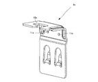
- FIG. 4 is a diagram showing an additional hanging bracket 4a of the indoor unit 100 of the ceiling-embedded air conditioner according to the first embodiment. Although only the additional hanging metal fittings 4a are shown here, the additional hanging metal fittings 4b to 4d have the same configuration as the additional hanging metal fittings 4a.
- the additional hanging bracket 4a has a substantially L-shape.
- the additional hanging bracket 4a is formed with a vertical hanging bolt mounting hole 10a for the second hanging bolt 8a and two horizontal screw holes 11a for fixing to the side surface of the housing 1 with screws. Has been done.
- the additional hanging brackets 4a to 4d have hanging bolt mounting holes 10a to 10d, respectively.
- the hanging bolt mounting hole 10a and the hanging bolt mounting hole 10c are formed at positions through which the second hanging bolt 8a and the second hanging bolt 8c hanging from the first channel 5a are passed.
- the hanging bolt mounting hole 10b and the hanging bolt mounting hole 10d are formed at positions through which the second hanging bolt 8b and the second hanging bolt 8d hanging from the second channel 5b are passed.
- FIG. 5 is a top view of the vicinity of the additional hanging bracket 4b and the second channel 5b of the indoor unit 100 of the ceiling-embedded air conditioner according to the first embodiment.
- FIG. 6 is a front view of the vicinity of the additional hanging bracket 4b and the second channel 5b of the indoor unit 100 of the ceiling-embedded air conditioner according to the first embodiment.
- the position of the hanging bolt mounting hole 10b of the additional hanging bracket 4b is outside the left side surface 1ab of the housing 1. That is, the hanging bolt mounting hole 10b of the additional hanging metal fitting 4b is provided at a position outside the left side surface 1ab. Further, the position of the hanging bolt mounting hole 10b of the additional hanging metal fitting 4b is a position through which the second hanging bolt 8b hanging from the second channel 5b is passed.
- the positions of the hanging bolt mounting holes 10b of the additional hanging bracket 4b have been described here, the positions of the hanging bolt mounting holes 10a of the additional hanging bracket 4a and the hanging bolts of the additional hanging bracket 4c have been described. The same applies to the position of the mounting hole 10c and the position of the hanging bolt mounting hole 10d of the additional hanging bracket 4d. That is, the position of the hanging bolt mounting hole 10a of the additional hanging bracket 4a has the hanging bolt mounting hole 10a at the position where the second hanging bolt 8a hanging from the first channel 5a is passed.
- the position of the hanging bolt mounting hole 10c of the additional hanging bracket 4c has a hanging bolt mounting hole 10c at a position through which the second hanging bolt 8c hanging from the second channel 5b is passed.
- the position of the hanging bolt mounting hole 10d of the additional hanging bracket 4d has a hanging bolt mounting hole 10d at a position through which the second hanging bolt 8d hanging from the second channel 5b is passed.
- the position of the hanging bolt mounting hole 10a of the additional hanging bracket 4a and the position of the hanging bolt mounting hole 10c of the additional hanging bracket 4c are determined in consideration of the horizontal width of the first channel 5a. Specifically, at the position of the hanging bolt mounting hole 10a and the position of the hanging bolt mounting hole 10c, the housing 1 and the first channel 5a are installed side by side in the horizontal direction, and the second hanging bolt 8a is vertically installed. It is a position that can be installed in. Similarly, the position of the hanging bolt mounting hole 10b of the additional hanging bracket 4b and the position of the hanging bolt mounting hole 10d of the additional hanging bracket 4d are determined in consideration of the horizontal width of the second channel 5b. ..
- the housing 1 and the second channel 5b are installed side by side in the horizontal direction, and the second hanging bolt 8a is vertically installed. It is a position that can be installed in.
- FIG. 7 is a top view of the vicinity of the standard hanging bracket 3b and the second channel 5b of the indoor unit 100 of the ceiling-embedded air conditioner according to the first embodiment.
- FIG. 8 is a front view of the indoor unit 100 of the ceiling-embedded air conditioner according to the first embodiment in the vicinity of the standard hanging bracket 3b and the second channel 5b.
- the hanging bolt mounting holes 12 of the standard hanging brackets 3a to 3d are on the right side of the housing 1. It enters the inside of the housing 1 from the side surface 1aa and the left side surface 1ab. Therefore, the positions of the second hanging bolts 8a to 8d are also inside the housing 1, and the positions of the first channel 5a and the second channel 5b holding the second hanging bolts 8a to 8d are also on the right side of the housing 1. It is inside the side surface 1aa and the left side surface 1ab.
- the first channel 5a and the second channel 5b In order to arrange the first channel 5a and the second channel 5b so that the housing 1 does not overlap, the first channel 5a and the second channel 5b must be arranged above the housing 1. Therefore, when the housing 1 is hung using the standard hanging metal fittings 3a to 3d, a large space is required for the ceiling as shown in FIG.
- the positions of the hanging bolt mounting holes 10a to 10d are such that the housing 1 and the first channel 5a and the second channel 5b are horizontal. It is formed at a position where it can be arranged side by side in the direction. Therefore, the housing 1 and the first channel 5a and the second channel 5b can be arranged side by side in the horizontal direction. As a result, as shown in FIG. 6, the housing 1 can be hung in a small space in the vertical direction for mounting the indoor unit 100 on the ceiling, as compared with the case where the housing 1 is hung by the standard hanging metal fitting 3.
- the housing 1 of the indoor unit 100 of the ceiling-embedded air conditioner according to the first embodiment includes standard hanging metal fittings 3a to 3d in addition to the additional hanging metal fittings 4a to 4d. Therefore, even if the housing 1 and the first channel 5a and the second channel 5b cannot be arranged side by side in the ceiling space, if the height of the attic space is sufficient, the indoor unit 100 Can be installed.
- the housing 1 of the indoor unit 100 may be a rectangular parallelepiped or a cube.
- Embodiment 2 Next, the indoor unit 100 of the ceiling-embedded air conditioner according to the second embodiment will be described.
- the mounting positions of the additional hanging brackets 4a to 4d are the additional suspension of the indoor unit 100 of the ceiling-embedded air conditioner according to the second embodiment. It is different from the mounting position of the metal fittings 4a to 4d.
- FIG. 9 is a top view of the housing 1 of the indoor unit 100A of the ceiling-embedded air conditioner according to the second embodiment.
- a pipe take-out portion 1c is provided near the side surface Cc of the corner portion.
- two additional hanging metal fittings 4c and an additional hanging metal fitting 4d are provided on the back side side surface 1ad.
- two additional hanging metal fittings 4a and an additional hanging metal fitting 4b are provided on the front side side surface 1ac facing the back side side surface 1ad.
- the first channel 5a is arranged so that the longitudinal direction is along the front side surface 1ac of the housing 1.
- the second channel 5b is arranged so that the longitudinal direction is along the back side side surface 1ad of the housing 1.
- the additional hanging brackets 4a to 4d have hanging bolt mounting holes 10a to 10d, respectively.
- the hanging bolt mounting hole 10a and the hanging bolt mounting hole 10b are outside the front side surface 1ac of the housing 1. That is, they are formed at positions through which the second hanging bolt 8a and the second hanging bolt 8b hanging from the first channel 5a are passed.
- the hanging bolt mounting hole 10c and the hanging bolt mounting hole 10d are outside the back side side surface 1ad of the housing 1. That is, they are formed at positions through which the second hanging bolt 8c and the second hanging bolt 8d hanging from the second channel 5b are passed.
- the indoor unit 100 of the ceiling-embedded air conditioner is small for mounting the indoor unit on the ceiling. Can be hung in space.
- Embodiment 3 Next, the indoor unit 100 of the ceiling-embedded air conditioner according to the second embodiment will be described.
- the mounting positions of the additional hanging brackets 4a to 4d are the addition of the indoor unit 100 of the ceiling-embedded air conditioner according to the first and second embodiments. It is different from the mounting position of the hanging brackets 4a to 4d.
- FIG. 10 is a top view of the housing 1 of the indoor unit 100B of the ceiling-embedded air conditioner according to the third embodiment. As shown in FIG. 10, in the indoor unit 100 of the ceiling-embedded air conditioner according to the second embodiment, additional hanging metal fittings 4a to 4d are attached to the side surfaces Ca to Cd of the corners, respectively.
- the additional hanging brackets 4a to 4d have hanging bolt mounting holes 10a to 10d, respectively.
- the hanging bolt mounting hole 10a and the hanging bolt mounting hole 10c are located on the outside of the right side surface 1aa, respectively. That is, they are formed at positions through which the second hanging bolt 8a and the second hanging bolt 8c hanging from the first channel 5a are passed.
- the hanging bolt mounting hole 10b and the hanging bolt mounting hole 10d are located on the outside of the left side surface 1ab, respectively. That is, they are formed at positions through which the second hanging bolt 8b and the second hanging bolt 8d hanging from the second channel 5b are passed.
- the indoor unit 100 of the ceiling-embedded air conditioner is placed in the ceiling in a small ceiling space as in the first and second embodiments. Can be hung on.
- the second hanging bolts 8a to 8d of the embodiment are also referred to as hanging bolts
- the additional hanging metal fittings 4a to 4d are also referred to as the first hanging metal fittings
- the standard hanging metal fittings 3a to 3d are also referred to as a second hanging metal fitting.
- the embodiment is presented as an example and is not intended to limit the scope of the embodiment.
- the embodiment can be implemented in various other forms, and various omissions, replacements, and changes can be made without departing from the gist of the embodiment. These embodiments and variations thereof are included in the scope and gist of the embodiments.
- 1 housing 1aa right side, 1ab left side, 1ac front side, 1ad back side, 1b slope, 1c pipe take-out part, Ca-Cd corner side, 2 decorative panel, 2a panel top surface, 3a-3d Standard hanging brackets, 4a-4d additional hanging brackets, 5a 1st channel, 5b 2nd channel, 6 ceiling slabs, 7 ceiling materials, 8a-8d 2nd hanging bolts, 9a-9d 1st hanging bolts, 10a ⁇ 10d Hanging bolt mounting hole, 11a screw hole, 12 hanging bolt mounting hole, 21 nut, 22 bolt hole, 100, 100A, 100B indoor unit.
Landscapes
- Engineering & Computer Science (AREA)
- Chemical & Material Sciences (AREA)
- Combustion & Propulsion (AREA)
- Mechanical Engineering (AREA)
- General Engineering & Computer Science (AREA)
- Air Filters, Heat-Exchange Apparatuses, And Housings Of Air-Conditioning Units (AREA)
Priority Applications (2)
| Application Number | Priority Date | Filing Date | Title |
|---|---|---|---|
| JP2021566749A JP7350090B2 (ja) | 2019-12-27 | 2019-12-27 | 天井埋め込み型空気調和機の室内機 |
| PCT/JP2019/051541 WO2021131049A1 (ja) | 2019-12-27 | 2019-12-27 | 天井埋め込み型空気調和機の室内機 |
Applications Claiming Priority (1)
| Application Number | Priority Date | Filing Date | Title |
|---|---|---|---|
| PCT/JP2019/051541 WO2021131049A1 (ja) | 2019-12-27 | 2019-12-27 | 天井埋め込み型空気調和機の室内機 |
Publications (1)
| Publication Number | Publication Date |
|---|---|
| WO2021131049A1 true WO2021131049A1 (ja) | 2021-07-01 |
Family
ID=76572968
Family Applications (1)
| Application Number | Title | Priority Date | Filing Date |
|---|---|---|---|
| PCT/JP2019/051541 Ceased WO2021131049A1 (ja) | 2019-12-27 | 2019-12-27 | 天井埋め込み型空気調和機の室内機 |
Country Status (2)
| Country | Link |
|---|---|
| JP (1) | JP7350090B2 (https=) |
| WO (1) | WO2021131049A1 (https=) |
Citations (3)
| Publication number | Priority date | Publication date | Assignee | Title |
|---|---|---|---|---|
| JPS52155346U (https=) * | 1976-05-20 | 1977-11-25 | ||
| JPH09236312A (ja) * | 1996-02-27 | 1997-09-09 | Daikin Ind Ltd | 天井埋込型空気調和機の固定構造 |
| JP2002364910A (ja) * | 2001-06-07 | 2002-12-18 | Hitachi Ltd | 天井埋込形空気調和機 |
Family Cites Families (1)
| Publication number | Priority date | Publication date | Assignee | Title |
|---|---|---|---|---|
| JP5911318B2 (ja) | 2012-02-01 | 2016-04-27 | 三菱電機株式会社 | 天井吊り下げ型空気調和機 |
-
2019
- 2019-12-27 JP JP2021566749A patent/JP7350090B2/ja active Active
- 2019-12-27 WO PCT/JP2019/051541 patent/WO2021131049A1/ja not_active Ceased
Patent Citations (3)
| Publication number | Priority date | Publication date | Assignee | Title |
|---|---|---|---|---|
| JPS52155346U (https=) * | 1976-05-20 | 1977-11-25 | ||
| JPH09236312A (ja) * | 1996-02-27 | 1997-09-09 | Daikin Ind Ltd | 天井埋込型空気調和機の固定構造 |
| JP2002364910A (ja) * | 2001-06-07 | 2002-12-18 | Hitachi Ltd | 天井埋込形空気調和機 |
Also Published As
| Publication number | Publication date |
|---|---|
| JPWO2021131049A1 (https=) | 2021-07-01 |
| JP7350090B2 (ja) | 2023-09-25 |
Similar Documents
| Publication | Publication Date | Title |
|---|---|---|
| US9200729B2 (en) | Combination hanger and reinforcement bracket | |
| US8474200B2 (en) | Suspended ceiling grid system | |
| CN104748353B (zh) | 设备安装装置以及室内机 | |
| JP6344567B2 (ja) | 空気調和機の室外機 | |
| WO2021131049A1 (ja) | 天井埋め込み型空気調和機の室内機 | |
| US10927555B2 (en) | Method for improving the ventilation effectiveness of large conditioned air plenum environments including such environments in multilevel raised floor electro-mechanical distribution systems | |
| JP6430582B2 (ja) | 目隠し板 | |
| JP6419301B2 (ja) | 室内機および冷凍サイクル装置 | |
| US12442544B2 (en) | Ceiling mounted evaporator blower | |
| JPS6314258Y2 (https=) | ||
| JP6220739B2 (ja) | 設備フレーム及び設備配置構造 | |
| RU2856991C1 (ru) | Система регулирования высоты монтажного положения воздухораспределителя | |
| JP7340987B2 (ja) | 室内機の吊り下げ具 | |
| JPH038406A (ja) | 組合せ型エアコンユニット | |
| CN209622977U (zh) | 空调的支撑结构及具有其的集装箱 | |
| JP6967266B2 (ja) | 間仕切壁構造および固定金具 | |
| KR100804605B1 (ko) | 천장카세트 에어컨의 설치구조 | |
| US11732923B2 (en) | Air flow producer assembly for ceiling mounting | |
| WO2019225278A1 (ja) | 空調室内機 | |
| JP7705230B2 (ja) | ダクトシステム | |
| JPH0116981Y2 (https=) | ||
| JP2527406Y2 (ja) | 天井埋込型空気調和機 | |
| JP2002364910A (ja) | 天井埋込形空気調和機 | |
| JP2003227640A (ja) | サーキュレータ及び空気調和システム | |
| JP5965209B2 (ja) | ユニット式建物の機器設置構造 |
Legal Events
| Date | Code | Title | Description |
|---|---|---|---|
| 121 | Ep: the epo has been informed by wipo that ep was designated in this application |
Ref document number: 19957768 Country of ref document: EP Kind code of ref document: A1 |
|
| WWE | Wipo information: entry into national phase |
Ref document number: 2021566749 Country of ref document: JP |
|
| NENP | Non-entry into the national phase |
Ref country code: DE |
|
| 122 | Ep: pct application non-entry in european phase |
Ref document number: 19957768 Country of ref document: EP Kind code of ref document: A1 |