WO2021130801A1 - 通信システムおよび通信方法 - Google Patents
通信システムおよび通信方法 Download PDFInfo
- Publication number
- WO2021130801A1 WO2021130801A1 PCT/JP2019/050267 JP2019050267W WO2021130801A1 WO 2021130801 A1 WO2021130801 A1 WO 2021130801A1 JP 2019050267 W JP2019050267 W JP 2019050267W WO 2021130801 A1 WO2021130801 A1 WO 2021130801A1
- Authority
- WO
- WIPO (PCT)
- Prior art keywords
- communication device
- processor
- identification information
- adjustment
- adjustment value
- Prior art date
- Legal status (The legal status is an assumption and is not a legal conclusion. Google has not performed a legal analysis and makes no representation as to the accuracy of the status listed.)
- Ceased
Links
Images












Classifications
-
- H—ELECTRICITY
- H04—ELECTRIC COMMUNICATION TECHNIQUE
- H04N—PICTORIAL COMMUNICATION, e.g. TELEVISION
- H04N23/00—Cameras or camera modules comprising electronic image sensors; Control thereof
- H04N23/60—Control of cameras or camera modules
-
- H—ELECTRICITY
- H04—ELECTRIC COMMUNICATION TECHNIQUE
- H04N—PICTORIAL COMMUNICATION, e.g. TELEVISION
- H04N21/00—Selective content distribution, e.g. interactive television or video on demand [VOD]
- H04N21/20—Servers specifically adapted for the distribution of content, e.g. VOD servers; Operations thereof
- H04N21/23—Processing of content or additional data; Elementary server operations; Server middleware
- H04N21/242—Synchronisation processes, e.g. processing of PCR [Programme Clock References]
-
- H—ELECTRICITY
- H04—ELECTRIC COMMUNICATION TECHNIQUE
- H04N—PICTORIAL COMMUNICATION, e.g. TELEVISION
- H04N21/00—Selective content distribution, e.g. interactive television or video on demand [VOD]
- H04N21/40—Client devices specifically adapted for the reception of or interaction with content, e.g. set-top-box [STB]; Operations thereof
- H04N21/43—Processing of content or additional data, e.g. demultiplexing additional data from a digital video stream; Elementary client operations, e.g. monitoring of home network or synchronising decoder's clock; Client middleware
-
- H—ELECTRICITY
- H04—ELECTRIC COMMUNICATION TECHNIQUE
- H04N—PICTORIAL COMMUNICATION, e.g. TELEVISION
- H04N5/00—Details of television systems
- H04N5/76—Television signal recording
- H04N5/91—Television signal processing therefor
- H04N5/93—Regeneration of the television signal or of selected parts thereof
- H04N5/935—Regeneration of digital synchronisation signals
-
- H—ELECTRICITY
- H04—ELECTRIC COMMUNICATION TECHNIQUE
- H04N—PICTORIAL COMMUNICATION, e.g. TELEVISION
- H04N7/00—Television systems
- H04N7/18—Closed-circuit television [CCTV] systems, i.e. systems in which the video signal is not broadcast
- H04N7/183—Closed-circuit television [CCTV] systems, i.e. systems in which the video signal is not broadcast for receiving images from a single remote source
Definitions
- the present invention relates to a communication system and a communication method.
- a wireless system that has a transmitting terminal (imaging terminal) and a receiving terminal (display terminal) and transmits video data in real time. It is necessary to synchronize the imaging timing on the transmitting terminal with the display timing on the receiving terminal. For example, the timing at each terminal is synchronized with the vertical synchronization signal. In the following, the vertical sync signal will be referred to as Vsync.
- the imaging timing at the transmitting terminal is synchronized with the imaging Vsync
- the display timing at the receiving terminal is synchronized with the display Vsync.
- Each Vsync is generated based on the source vibration clock output from the oscillator mounted on each terminal. Even when each terminal is designed so that the oscillation period of the source vibration clock of each terminal is the same, the oscillation cycle of the source vibration clock of each terminal has a deviation of the period peculiar to each terminal. Therefore, the cycle of each Vsync is unique to each terminal.
- a wireless packet for synchronization is used to synchronize the imaged Vsync and the displayed Vsync.
- the radio packet will be referred to as a synchronous packet.
- Communication quality may deteriorate due to changes in the wireless environment, or interference may occur in communication with other systems, and the period in which synchronous packets are not received may continue. In that case, the timing of Vsync between the terminals gradually deviates due to the influence of the Vsync cycle peculiar to each terminal. If the period during which the synchronization packet is not received continues, the timing of the imaging Vsync and the timing of the display Vsync are significantly deviated, and the video data is lost. When the video data is missing, the receiving terminal cannot display the video corresponding to the missing video data. Therefore, the smoothness of the image may be lost or blackout may occur.
- the Vsync cycle is adjusted each time the terminal is turned on. It takes a long time to complete the adjustment of the Vsync cycle. Only the phase of Vsync is adjusted until the adjustment of the period of Vsync is completed. At the timing when the phase adjustment is performed, the timing of Vsync between the terminals is synchronized. However, there is a possibility that the timing of Vsync between the terminals will be shifted by the time the phase adjustment is performed next, and the video data will be lost.
- An object of the present invention is to provide a communication system and a communication method capable of matching the cycles of synchronization signals of a transmitting terminal and a receiving terminal in a short time.
- the communication system has a transmitting terminal and a receiving terminal.
- the transmitting terminal has a first signal generator and a first communication device.
- the first signal generator generates a first synchronization signal that defines the imaging cycle.
- the first communication device transmits an image generated by an imaging device that captures an image of a subject according to the first synchronization signal.
- the receiving terminal has a second communication device and a second signal generator.
- the second communicator receives the image transmitted by the first communicator.
- the second signal generator generates a second sync signal that defines the display period.
- the image received by the second communication device is output to a display device that displays the image according to the second synchronization signal.
- One of the transmitting terminal and the receiving terminal has a recording medium and a processor that adjusts one of the first signal generator and the second signal generator.
- the processor calculates an adjustment value indicating a difference between the imaging cycle and the display cycle.
- the processor adjusts the first signal generator based on the adjusted value to match the imaging cycle with the display cycle.
- the processor adjusts the second signal generator based on the adjusted value to match the imaging cycle with the display cycle.
- the connection history in which the adjustment information and the identification information are associated with each other is recorded in the recording medium.
- the adjustment information directly or indirectly indicates the adjustment value.
- the identification information identifies one of the first communication device and the second communication device.
- the said The processor adjusts the first signal generator based on the adjustment value indicated by the adjustment information associated with the identification information in the connection history.
- the said The processor adjusts the second signal generator based on the adjustment value indicated by the adjustment information associated with the identification information in the connection history.
- the transmitting terminal may further have a first temperature sensor.
- the receiving terminal may further have a second temperature sensor.
- the temperature measured by each of the first temperature sensor and the second temperature sensor may be associated with the adjustment information and the identification information.
- the processor corrects the adjustment value based on the temperature measured by each of the first temperature sensor and the second temperature sensor and the temperature associated with the identification information in the connection history. You may decide whether or not to do so.
- the processor uses the adjustment value indicated by the adjustment information associated with the identification information in the connection history as the first synchronization signal and the second synchronization signal. It may be corrected based on the temperature characteristic of each source clock. In the first case, the processor may adjust the first signal generator based on the corrected adjustment value. In the second case, the processor may adjust the second signal generator based on the corrected adjustment value.
- the transmitting terminal may have the processor.
- the processor may acquire identification information that identifies the second communicator.
- the processor may record the connection history in which the adjustment information and the identification information are associated with each other on the recording medium.
- the processor determines whether or not the newly acquired identification information is the same as the identification information recorded on the recording medium. May be judged.
- the processor causes the adjustment information associated with the identification information in the connection history.
- the first signal generator may be adjusted based on the adjustment value shown.
- the image pickup apparatus may have one or more first wireless modules.
- the first communication device may be the first wireless module.
- the receiving terminal may have two or more second radio modules.
- the second communication device may be the second wireless module.
- the first communication device and the second communication device may carry out wireless communication.
- the identification information may be the MAC (Media Access Control) address of the second wireless module.
- the identification information of each of the two or more second radio modules may be associated with the adjustment information.
- the receiving terminal may have the processor.
- the processor may acquire identification information that identifies the first communicator.
- the processor may record the connection history in which the adjustment information and the identification information are associated with each other on the recording medium.
- the processor determines whether or not the newly acquired identification information is the same as the identification information recorded on the recording medium. May be judged.
- the processor causes the adjustment information associated with the identification information in the connection history.
- the second signal generator may be adjusted based on the adjustment value shown.
- the communication system may have two or more receiving terminals.
- the communication method includes a calculation step executed by a processor of one of the transmitting terminal and the receiving terminal, a recording medium, and a first adjustment step executed by the processor. It has the recording medium and a second adjustment step performed by the processor.
- the transmitting terminal has a first signal generator and a first communication device.
- the first signal generator generates a first synchronization signal that defines the imaging cycle.
- the first communication device transmits an image generated by an imaging device that captures an image of a subject according to the first synchronization signal.
- the receiving terminal has a second communication device and a second signal generator.
- the second communicator receives the image transmitted by the first communicator.
- the second signal generator generates a second sync signal that defines the display period.
- the image received by the second communication device is output to a display device that displays the image according to the second synchronization signal.
- the processor calculates an adjustment value indicating a difference between the imaging cycle and the display cycle in the calculation step.
- the processor adjusts the first signal generator based on the adjustment value in the first adjustment step to perform the imaging cycle and the display cycle. To match.
- the processor adjusts the second signal generator based on the adjustment value in the first adjustment step to perform the imaging cycle and the display cycle.
- the connection history in which the adjustment information and the identification information are associated with each other is recorded in the recording medium.
- the adjustment information directly or indirectly indicates the adjustment value.
- the identification information identifies one of the first communication device and the second communication device.
- the processor adjusts the first signal generator based on the adjustment value indicated by the adjustment information associated with the identification information in the connection history.
- the processor adjusts the second signal generator based on the adjustment value indicated by the adjustment information associated with the identification information in the connection history.
- the communication system and the communication method can match the period of the synchronization signal of the transmitting terminal and the receiving terminal in a short time.
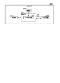
- FIG. 1 shows the configuration of the communication system 10 according to the first embodiment of the present invention.
- the communication system 10 shown in FIG. 1 has a transmitting terminal 100 and a receiving terminal 200.
- the transmitting terminal 100 and the receiving terminal 200 carry out communication for transmitting an image (video).
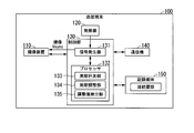
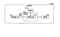
- FIG. 2 shows the configuration of the transmitting terminal 100.
- the transmission terminal 100 shown in FIG. 2 includes an image pickup device 110, an oscillator 120, a control unit 130, a communication device 140 (first communication device), and a recording medium 150.
- the control unit 130 includes a signal generator 131 (first signal generator) and a processor 132.
- FIG. 3 shows the configuration of the receiving terminal 200.
- the receiving terminal 200 shown in FIG. 3 has a communication device 210 (second communication device), an oscillator 220, a control unit 230, and a display device 240.
- the control unit 230 has a signal generator 231 (second signal generator).
- the signal generator 131 generates a first synchronization signal that defines the imaging cycle.
- the image pickup apparatus 110 takes an image of the subject according to the first synchronization signal.
- the communication device 140 transmits the image generated by the image pickup device 110.
- the communication device 210 receives the image transmitted by the communication device 140.
- the signal generator 231 generates a second synchronization signal that defines the display period.
- the image received by the communication device 210 is output to the display device 240.
- the display device 240 displays an image according to the second synchronization signal.
- the processor 132 calculates an adjustment value indicating the difference between the imaging cycle and the display cycle.
- the processor 132 adjusts the signal generator 131 based on the adjustment value to match the imaging cycle and the display cycle.
- the connection history in which the adjustment information and the identification information are associated with each other is recorded on the recording medium 150.
- the adjustment information directly or indirectly indicates the adjustment value.
- the identification information identifies one of the communication device 140 and the communication device 210. When the communication device 140 and the communication device 210 are reconnected to each other, if the identification information corresponding to one of the communication device 140 and the communication device 210 is recorded in the recording medium 150, the processor 132 and the identification information in the connection history.
- the signal generator 131 is adjusted based on the adjustment value indicated by the associated adjustment information.
- the processor 132 acquires identification information for identifying the communication device 210.
- the communication device 210 transmits the identification information to the communication device 140.
- the processor 132 receives the identification information from the communication device 210 by using the communication device 140.
- the processor 132 calculates the adjustment value
- the processor 132 records the connection history in which the adjustment information and the identification information are associated with each other on the recording medium 150.
- the processor 132 determines whether or not the newly acquired identification information is the same as the identification information recorded on the recording medium 150.
- the processor 132 determines that the newly acquired identification information is the same as the identification information recorded on the recording medium 150, the processor 132 is based on the adjustment value indicated by the adjustment information associated with the identification information in the connection history. Adjust the signal generator 131.
- the image pickup device 110 is an image sensor such as a CMOS (Complementary Metal Oxide Sensor) sensor.
- the image pickup apparatus 110 generates an image at the timing indicated by the vertical synchronization signal (imaging Vsync) generated by the signal generator 131.
- the imaging Vsync includes repetitive pulses.
- the period of the imaging Vsync is the time interval at which the pulse is generated.
- the period of the imaging Vsync indicates the imaging cycle.
- the speed (frame rate) at which the image pickup apparatus 110 is driven is not limited to 60 fps.
- One image (1 frame) is generated for each imaging cycle.
- the image pickup apparatus 110 generates an image by continuously generating a plurality of images.
- the image pickup apparatus 110 outputs an image to the control unit 130.
- the oscillator 120 is a crystal oscillator.
- the oscillator 120 generates a source clock and outputs the source clock to the signal generator 131.
- the signal generator 131 is a sink generator.
- the signal generator 131 generates a first synchronization signal based on the source vibration clock output from the oscillator 120.
- the first synchronization signal includes a vertical synchronization signal (imaging Vsync) and a horizontal synchronization signal.
- the horizontal sync signal includes repetitive pulses.
- the period of the horizontal synchronization signal is the time interval at which the pulse is generated.
- the period of the horizontal synchronization signal indicates the timing of scanning each row in the pixel array of the image pickup apparatus 110. In the following, an example in which the period of the imaging Vsync is used to adjust the period of the synchronization signal will be described.
- the signal generator 131 outputs the first synchronization signal to the image pickup apparatus 110.
- the signal generator 131 has a cycle counter that defines the cycle of the imaging Vsync. By adjusting the value measured by the cycle counter of the signal generator 131, the cycle of the imaging Vsync is adjusted.
- the processor 132 is at least one of a CPU (Central Processing Unit), a DSP (Digital Signal Processor), and a GPU (Graphics Processing Unit).
- the processor 132 may be configured by a logic circuit such as an ASIC (Application Specific Integrated Circuit) or an FPGA (Field-Programmable Gate Array).
- the transmitting terminal 100 may have a plurality of processors.
- the processor 132 outputs the image output from the image pickup device 110 to the communication device 140.
- the processor 132 has functions as a cycle measurement unit 133, a cycle adjustment unit 134, and an adjustment value detection unit 135.
- the cycle measurement unit 133 measures the difference between the imaging cycle and the display cycle, and calculates an adjustment value indicating the difference.
- the cycle adjustment unit 134 adjusts the signal generator 131 based on the adjustment value.
- the signal generator 131 is adjusted so that the cycle (imaging cycle) of the imaging Vsync generated by the signal generator 131 matches the display cycle.
- the adjustment value detection unit 135 determines whether or not the identification information received from the communication device 210 is included in the connection history recorded on the recording medium 150. To do. When the identification information received from the communication device 210 is included in the connection history, the adjustment value detection unit 135 detects an adjustment value that can be used for adjusting the imaging cycle. When the adjustment value detection unit 135 determines that the identification information received from the communication device 210 is included in the connection history, the cycle adjustment unit 134 signals based on the adjustment value associated with the identification information in the connection history. Adjust the generator 131.
- the oscillation cycle of the source clock generated by the oscillator 120 has a period deviation peculiar to the oscillator 120. This deviation is the difference between the ideal design period and the actual period. Similarly, the oscillation period of the source clock generated by the oscillator 220 has a period deviation inherent in the oscillator 220. If the environment in which the transmitting terminal 100 and the receiving terminal 200 are arranged does not change, it is assumed that the deviation of the oscillation cycle of the source clock does not change. Therefore, when the communication device 140 and the communication device 210 are reconnected to each other, the adjustment value used in the past connection can be used for the adjustment of the imaging cycle.
- the processor 132 may read the program and execute the read program.
- the program contains instructions that specify the operation of processor 132. That is, the function of the processor 132 may be realized by software.
- the program may be provided by a "computer-readable recording medium” such as flash memory.
- the program may be transmitted from the computer holding the program to the transmission terminal 100 via the transmission medium or by the transmission wave in the transmission medium.
- a "transmission medium” for transmitting a program is a medium having a function of transmitting information.
- the medium having a function of transmitting information includes a network (communication network) such as the Internet and a communication line (communication line) such as a telephone line.
- the above-mentioned program may realize a part of the above-mentioned function.
- the above-mentioned program may be a difference file (difference program). The combination of the program already recorded in the computer and the difference program may realize the above-mentioned function.
- the communication device 140 communicates with the communication device 210.
- the communication device 140 is a wireless module having an antenna and a wireless circuit.
- the communication device 140 carries out wireless communication by radiating a radio wave to the communication device 210 or receiving a radio wave radiated from the communication device 210.
- the communication device 140 may be connected to a cable and carry out wired communication.
- the processor 132 transmits an image or information to the receiving terminal 200 by using the communication device 140. Specifically, the processor 132 controls the communication device 140 so that the image or information is transmitted to the receiving terminal 200. That is, the processor 132 causes the communication device 140 to transmit an image or information for the receiving terminal 200. As a result, the communication device 140 transmits the image or information to the receiving terminal 200.
- the processor 132 receives information from the receiving terminal 200 by using the communication device 140. Specifically, the processor 132 controls the communication device 140 so that the information is received from the receiving terminal 200. That is, the processor 132 causes the communication device 140 to receive the information from the receiving terminal 200. As a result, the communication device 140 receives the information from the receiving terminal 200.
- the recording medium 150 is a volatile or non-volatile recording medium.
- the recording medium 150 RAM (Random Access Memory), DRAM (DynamicRandom Access Memory), SRAM (Static Random Access Memory), EEPROM (Electrically Erasable Programmable Read-Only Memory), FRAM (registered trademark) (Ferroelectric Random Access Memory ), Flash memory, and at least one of the hard disk drives.
- the recording medium 150 stores the connection history.
- the adjustment value calculated by the periodic measurement unit 133 and the identification information for identifying the communication device 210 are associated with each other.
- the connection history may include a plurality of combinations of adjustment values and identification information.
- the image pickup device 110 is included in the transmission terminal 100.
- the imaging device 110 is not essential to the transmitting terminal 100.
- the image pickup apparatus 110 may be arranged outside the transmission terminal 100 and may be connected to the transmission terminal 100 by wire or wirelessly.
- the recording medium 150 is included in the transmission terminal 100.
- the recording medium 150 is not essential to the transmitting terminal 100.
- the recording medium 150 may be arranged outside the transmission terminal 100 and may be connected to the transmission terminal 100 by wire or wirelessly.
- the communication device 210 communicates with the communication device 140.
- the communication device 210 is a wireless module having an antenna and a wireless circuit.
- the communication device 210 carries out wireless communication by radiating a radio wave to the communication device 140 or receiving a radio wave radiated from the communication device 140.
- the communication device 210 may be connected to a cable and carry out wired communication.
- the communication device 210 receives the image or information transmitted from the transmission terminal 100. Further, the communication device 210 transmits the information to the transmission terminal 100.
- the oscillator 220 is a crystal oscillator.
- the oscillator 220 generates a source clock and outputs the source clock to the signal generator 231.
- the control unit 230 outputs the image output from the communication device 210 to the display device 240.
- the signal generator 231 is a sink generator.
- the signal generator 231 generates a second synchronization signal based on the source vibration clock output from the oscillator 220.
- the second sync signal includes a vertical sync signal (display Vsync) and a horizontal sync signal.
- the period of the horizontal synchronization signal indicates the timing of scanning each line on the screen of the display device 240. In the following, an example in which the period of the display Vsync is used to adjust the period of the synchronization signal will be described.
- the signal generator 231 outputs the second synchronization signal to the display device 240.
- the control unit 230 may have a processor.
- the display device 240 is a monitor.
- the display device 240 is a liquid crystal display or an organic EL (Electroluminescence) display.
- the display device 240 displays an image at the timing indicated by the vertical synchronization signal (display Vsync) generated by the signal generator 231.
- the display Vsync includes repetitive pulses.
- the period of the display Vsync is the time interval at which the pulse is generated.
- the cycle of the display Vsync indicates the display cycle.
- the display cycle is 16.6 ms.
- the speed (frame rate) at which the display device 240 updates the image is not limited to 60 fps.
- One image (1 frame) is displayed for each display cycle.
- the display device 240 displays an image by continuously displaying a plurality of images.
- the display device 240 is included in the receiving terminal 200.
- the display device 240 is not essential to the receiving terminal 200.
- the display device 240 may be arranged outside the receiving terminal 200 and may be connected to the receiving terminal 200 by wire or wirelessly.
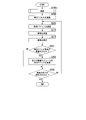
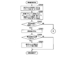
- FIG. 4 shows a procedure for operating the transmitting terminal 100.
- the processor 132 executes the connection process (step S100).
- the processor 132 connects to the communication device 210 of the receiving terminal 200 by using the communication device 140 in the connection process.
- the connection process is executed, a communication link between the transmitting terminal 100 and the receiving terminal 200 is established, and data communication becomes possible. Details of step S100 will be described later.
- the communication device 140 acquires the identification information of the communication device 210 by receiving the identification information of the communication device 210 from the communication device 210.
- the processor 132 determines whether or not the identification information received from the communication device 210 is included in the connection history recorded on the recording medium 150. As a result, the processor 132 determines whether or not the adjustment value is included in the connection history (step S105).
- the adjustment value and the identification information of the communication device 210 are not included in the connection history. If the identification information is not included in the connection history, the processor 132 determines that the adjustment value is not included in the connection history. When the communication device 140 and the communication device 210 have been connected to each other in the past, and the communication device 140 and the communication device 210 are connected to each other again, the adjustment value and the identification information of the communication device 210 are included in the connection history. When the identification information is included in the connection history, the processor 132 determines that the adjustment value is included in the connection history.
- the processor 132 determines in step S105 that the adjustment value is included in the connection history
- the processor 132 reads the adjustment value associated with the identification information received from the communication device 210 in the connection history from the recording medium 150. ..
- the processor 132 adjusts the period of the imaging Vsync by applying the adjusted value to the signal generator 131 (step S110). As a result, the period of the imaging Vsync and the period of the display Vsync match.
- the method of adjusting the cycle of the imaging Vsync in step S110 is the same as the method of adjusting the cycle of the imaging Vsync in step S1625 (FIG. 9) described later.
- the communication device 210 transmits a synchronization packet to the communication device 140 at each display Vsync cycle. For example, when the display cycle is 16.6 ms, the communication device 210 periodically transmits a synchronization packet to the communication device 140 at an interval of 16.6 ms.
- the synchronization packet contains information used to adjust the phase and period of the imaging Vsync. Since the synchronization adjustment process is executed at the transmission terminal 100, the synchronization packet is transmitted before a predetermined time of the timing at which the display Vsync pulse is output.
- step S120 the processor 132 performs phase adjustment (step S120).
- the processor 132 matches the phase of the imaging Vsync with the phase of the display Vsync by matching the timing of the imaging Vsync with the timing of the display Vsync. Details of step S120 will be described later.
- the processor 132 causes the imaging device 110 to perform imaging.
- the image pickup apparatus 110 performs imaging and generates an image (step S125).
- the processor 132 transmits an image to the communicator 210 by using the communicator 140 (step S130).
- An image that has undergone image processing such as compression may be transmitted.
- the processor 132 determines whether or not the end of imaging is instructed (step S135).
- the transmitting terminal 100 has an operation unit operated by the user.
- the processor 132 determines whether or not the end of imaging is instructed based on the operation result of the operation unit. For example, when the power of the transmission terminal 100 is instructed to be turned off, the processor 132 determines that the end of imaging is instructed. If the power of the transmitting terminal 100 is not instructed to be turned off, the processor 132 determines that the end of imaging is not instructed.
- step S135 When the processor 132 determines in step S135 that the end of imaging is instructed, the process shown in FIG. 4 ends. In this case, the processor 132 disconnects the connection between the communication device 140 and the communication device 210. If the processor 132 determines in step S135 that the end of imaging is not instructed, step S115 is executed.
- step S105 the communication device 140 waits for the reception of the synchronization packet.
- the communication device 140 receives the synchronization packet.
- the processor 132 acquires a synchronization packet from the communication device 140 (step S140).
- Step S145 is the same as step S120.
- the processor 132 causes the imaging device 110 to perform imaging.
- the image pickup apparatus 110 performs an image pickup according to the image pickup Vsync and generates an image (step S150).
- the processor 132 transmits an image to the communicator 210 by using the communicator 140 (step S155).
- step S155 the processor 132 performs periodic adjustment (step S160).
- step S160 the processor 132 matches the period of the imaging Vsync with the period of the display Vsync. Details of step S160 will be described later.
- step S160 the processor 132 associates the adjustment value calculated in step S160 with the identification information of the communication device 210.
- the processor 132 records the connection history including the adjustment value and the identification information on the recording medium 150 (step S165). After step S165, step S135 is executed.
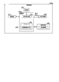
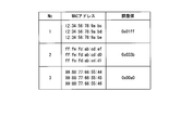
- FIG. 5 shows an example of the connection history recorded on the recording medium 150.
- the identification information and adjustment values in the same line are related to each other. For example, the identification information A0000xxxxxx and the adjustment value 0x01ff are associated with each other.
- the cycle adjustment is performed in step S160, and the adjustment value is recorded on the recording medium 150 in step S165.
- step S110 the adjustment value associated with the identification information is read from the recording medium 150, and the adjustment value is used to adjust the period of the imaging Vsync.
- the control unit 230 executes the connection process (step S200).
- the control unit 230 connects to the communication device 140 of the transmission terminal 100 by using the communication device 210 in the connection process. Details of step S200 will be described later.
- the communication device 210 transmits a synchronization packet to the communication device 140 (step S205).
- the communication device 210 receives an image from the communication device 140 (step S210).
- the received image is output to the display device 240 via the control unit 230.
- the display device 240 displays an image according to the display Vsync (step S215).
- step S215 the control unit 230 determines whether or not the end of the display has been instructed (step S220). For example, in step S130 shown in FIG. 4, when the processor 132 determines that the end of imaging is instructed, the processor 132 transmits the end instruction to the communication device 210 by using the communication device 140. When the end instruction is transmitted from the communication device 140, the communication device 210 receives the end instruction. When the communication device 210 receives the end instruction, the control unit 230 determines that the end of the display has been instructed. If the communication device 210 has not received the end instruction, the control unit 230 determines that the end of the display has not been instructed.
- the receiving terminal 200 may have an operation unit operated by the user.
- the control unit 230 may determine whether or not the end of the display is instructed based on the operation result of the operation unit. For example, when the power of the receiving terminal 200 is instructed to be turned off, the control unit 230 may determine that the end of the display is instructed. When the power off of the receiving terminal 200 is not instructed, the control unit 230 may determine that the end of the display is not instructed.
- step S220 When the control unit 230 determines that the end of the display is instructed in step S220, the process shown in FIG. 6 ends. In this case, the control unit 230 disconnects the connection between the communication device 210 and the communication device 140. If the control unit 230 determines in step S220 that the end of the display has not been instructed, step S205 is executed.
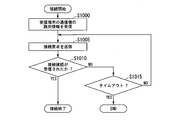
- FIG. 7 shows a procedure for operating the transmitting terminal 100 in the connection process.
- the communication device 140 stands by for receiving the identification information that identifies the communication device 210 of the receiving terminal 200.
- the identification information is transmitted from the communication device 210
- the communication device 140 receives the identification information.
- the processor 132 acquires the identification information from the communication device 140 (step S1000).
- step S1000 the processor 132 transmits a connection request to the communication device 210 by using the communication device 140 (step S1005).
- the communication device 210 receives the connection request and transmits the connection confirmation to the communication device 140.
- the communication device 140 receives the connection confirmation.
- the processor 132 determines whether or not the connection confirmation has been received (step S1010). For example, in step S1010, the processor 132 determines whether or not the connection confirmation has been received within a predetermined time from the timing when the connection request is transmitted.
- step S1010 When the processor 132 determines that the connection confirmation has been received in step S1010, the process shown in FIG. 7 ends, and step S105 shown in FIG. 4 is executed. In this case, the connection between the communication device 140 and the communication device 210 is established.
- the communication device 140 and the communication device 210 can carry out image communication.
- step S1015 the processor 132 determines whether or not a timeout has occurred. For example, the processor 132 determines whether or not the time elapsed from the timing when the connection request is first transmitted exceeds the predetermined time. If the time exceeds a predetermined time, the processor 132 determines that a timeout has occurred. If the time does not exceed the predetermined time, the processor 132 determines that the timeout has not occurred.
- step S1015 When the processor 132 determines that a timeout has occurred in step S1015, the processes shown in FIGS. 7 and 4 end. If the processor 132 determines in step S1015 that no timeout has occurred, step S1005 is executed.
- the communication device 140 receives the identification information from the communication device 210.
- the communication method of the identification information is not limited to this.
- the transmitting terminal 100 may have two or more communicators including the communicator 140, and the receiving terminal 200 may have two or more communicators including the communicator 210.
- the communication device of the transmission terminal 100 other than the communication device 140 may receive the identification information of the communication device 210 from the communication device of the reception terminal 200 other than the communication device 210. That is, the transmitting terminal 100 may receive the identification information from the receiving terminal 200 by using a communication device other than the communication device 140 used for transmitting the image.
- FIG. 8 shows a procedure for operating the transmitting terminal 100 in phase adjustment.
- the synchronization packet received in step S115 or step S140 includes a value indicating the timing of the next pulse of the display Vsync.
- the processor 132 extracts the value from the synchronous packet (step S1200).
- step S1200 the processor 132 calculates the timing of the next pulse of the imaging Vsync based on the value extracted from the synchronization packet.
- the processor 132 sets the calculated timing in the signal generator 131 (step S1205).
- step S1205 is executed, the process shown in FIG. 8 ends, and step S125 or step S150 shown in FIG. 4 is executed.
- the synchronization packet contains information indicating the time of the next pulse of the display Vsync.
- the processor 132 subtracts the time when the synchronization packet is received from the time of the next pulse of the display Vsync. As a result, the processor 132 calculates the time required until the timing of the next pulse of the imaging Vsync. The processor 132 adjusts the signal generator 131 to generate a pulse of the imaging Vsync when the calculated time has elapsed.
- step S115 or step S140 If the synchronization packet is not received in step S115 or step S140, the imaging is performed without performing the phase adjustment, and the image is transmitted.
- FIG. 9 shows a procedure of operation of the transmission terminal 100 in the cycle adjustment.
- a method similar to the method described in WO 2018/235258 can be applied to the periodic adjustment in the embodiments of the present invention.
- the processor 132 acquires the counter value CNT_A in the cycle of the imaging Vsync from the signal generator 131 (step S1600).
- the signal generator 131 has a counter for measuring time.
- the value of the counter increases from the initial value at the reference timing.
- the processor 132 acquires the counter value CNT_A at the timing when a pulse synchronized with the period of the imaging Vsync is generated.
- the counter value CNT_A corresponds to the length of a predetermined number of cycles of the imaging Vsync.
- the processor 132 extracts the frame counter value from the synchronization packet received in step S140.
- the frame counter value indicates the number of frame periods included in the period starting from the reference timing. For example, when the imaging cycle and the display cycle are 16.6 ms, the length of one frame period is 16.6 ms.
- the frame counter value corresponds to the frame number.
- the processor 132 calculates the counter value CNT_B in the period of the display Vsync based on the frame counter value (step S1605).
- the signal generator 231 of the receiving terminal 200 has a counter for measuring time.
- the value of the counter (counter value CNT_B) increases from the initial value at the reference timing.
- the counter value CNT_B increases by a fixed value in one frame period. For example, its fixed value is 1,000,000.
- the fixed value is not limited to 1,000,000.
- the processor 132 calculates the counter value CNT_B by multiplying the fixed value by the frame counter value.
- the fixed value may be recorded on the recording medium 150.
- the processor 132 may receive a fixed value from the communication device 210 by using the communication device 140.
- the fixed value may be stored in the synchronization packet.
- the processor 132 determines whether or not a predetermined time has elapsed (step S1610).
- the predetermined time is 60 seconds.
- the predetermined time may be a time other than 60 seconds.
- the processor 132 determines the time elapsed from the timing when the communication device 140 and the communication device 210 are connected to each other. If the time is shorter than the predetermined time, the processor 132 determines that the predetermined time has not elapsed. If the time is equal to or longer than the predetermined time, the processor 132 determines that the predetermined time has elapsed.
- step S140 is executed.
- the synchronization packet is repeatedly received and the counter value CNT_A and the counter value CNT_B are repeatedly acquired until the predetermined time elapses.
- the processor 132 measures the difference between the period of the imaging Vsync and the period of the display Vsync, and calculates an adjustment value indicating the difference (step S1615). ).
- a plurality of counter values CNT_A and a plurality of counter values CNT_B are acquired at a predetermined time.
- the processor 132 selects the counter value CNT_A and the counter value CNT_B at each of the two times included in the predetermined time.
- the processor 132 selects the counter value CNT_A (t0) and the counter value CNT_B (t0) at the time t0, and the counter value CNT_A (t1) and the counter value CNT_B (t1) at the time t1.
- Select t1 selects the counter value CNT_A (t0) and the counter value CNT_B (t0) at the time t0, and the counter value CNT_A (t1) and the counter value CNT_B (t1) at the time t1.
- the processor 132 calculates the period Ti of the imaging Vsync according to the following equation (1), and calculates the period Td of the display Vsync according to the following equation (2).
- Ti ⁇ CNT_A (t1) -CNT_A (t0) ⁇ / (t1-t0) ...
- Td ⁇ CNT_B (t1) -CNT_B (t0) ⁇ / (t1-t0) ...
- step S1620 the processor 132 determines whether or not periodic adjustment is necessary.
- step S1620 the processor 132 calculates the difference between the maximum value of the cycle counter of the signal generator 131 and the maximum value of the cycle counter of the signal generator 231. The maximum value of each cycle counter will be described later.
- step S1620 the processor 132 determines whether or not the adjustment value is smaller than the difference. If the adjustment value is smaller than the difference, the processor 132 determines that periodic adjustment is necessary. If the adjustment value is larger than the difference, the processor 132 determines that the periodic adjustment is not necessary. For example, when the difference is a value corresponding to 50 ppm and the adjusted value is a value corresponding to 10 ppm, the processor 132 determines that periodic adjustment is necessary.
- the signal generator 131 has a cycle counter that measures the cycle of the imaging Vsync.
- the value of the cycle counter increases from the initial value at the timing when the cycle of the imaging Vsync starts.
- the value of the cycle counter reaches the preset maximum value, the value of the cycle counter is reset to the initial value.
- the signal generator 131 generates a pulse of the imaging Vsync based on the value of the cycle counter. For example, the signal generator 131 generates a pulse of the imaging Vsync at the timing when the value of the cycle counter is reset.
- the signal generator 231 has a cycle counter that measures the cycle of the display Vsync.
- the value of the cycle counter is increased from the initial value at the timing when the cycle of the display Vsync is started.
- the value of the cycle counter reaches the preset maximum value, the value of the cycle counter is reset to the initial value.
- the signal generator 231 generates a pulse of display Vsync based on the value of its cycle counter. For example, the signal generator 231 generates a pulse of display Vsync at the timing when the value of the cycle counter is reset.
- the maximum value of each cycle counter of the signal generator 131 and the signal generator 231 may be recorded on the recording medium 150.
- the processor 132 may receive the maximum value of the cycle counter of the signal generator 231 from the communication device 210 by using the communication device 140.
- the maximum value of the period counter of the signal generator 231 may be stored in the synchronization packet.
- step S1620 When the processor 132 determines in step S1620 that the cycle adjustment is necessary, the processor 132 updates the value of the cycle counter of the signal generator 131 based on the calculated adjustment value (step S1625). By executing step S1625, the processor 132 matches the period of the imaging Vsync with the period of the display Vsync.
- the processor 132 calculates a new maximum value by subtracting the adjustment value from the maximum value of the cycle counter of the signal generator 131 in step S1625 in order to shorten the period of the imaging Vsync. In step S1625, the processor 132 updates the maximum value of the period counter of the signal generator 131 to a new maximum value.
- the processor 132 calculates a new maximum value by adding an adjustment value to the maximum value of the cycle counter of the signal generator 131 in step S1625 in order to lengthen the period of the imaging Vsync. In step S1625, the processor 132 updates the maximum value of the period counter of the signal generator 131 to a new maximum value.
- step S1625 When step S1625 is executed, the process shown in FIG. 9 is completed, and step S165 shown in FIG. 4 is executed.
- the processor 132 determines in step S1620 that the cycle adjustment is not necessary, the process shown in FIG. 9 ends, and step S165 shown in FIG. 4 is executed.
- step S1625 The adjustment value calculated in step S1625 is recorded on the recording medium 150 in step S165 shown in FIG. If the processor 132 determines in step S1620 that the cycle adjustment is not necessary, information indicating that the cycle adjustment is not necessary may be recorded in the recording medium 150 in step S165 shown in FIG. The information is associated with the identification information of the communication device 210.
- step S105 shown in FIG. 4 when the processor 132 determines that the identification information received from the communication device 210 is included in the connection history, the processor 132 may execute the following processing. If the adjustment value is associated with the identification information in the connection history, the processor 132 executes step S110 described above. When the information indicating that the cycle adjustment is not necessary is associated with the identification information in the connection history, the processor 132 may execute step S115 without executing step S110.
- the adjustment value for adjusting the cycle of the imaging Vsync is the difference between the cycle of the imaging Vsync and the cycle of the display Vsync. If the specifications of the source vibration clock generated by the oscillator 120 of the transmitting terminal 100 and the specifications of the source vibration clock generated by the oscillator 220 of the receiving terminal 200 are the same, even if the difference in the period deviation is used as the adjustment value. Good. Specifically, the difference (first value) between the ideal design period of the imaging Vsync and the actual period of the imaging Vsync is calculated. The first value indicates the deviation of the period of the imaging Vsync.
- the difference (second value) between the ideal display Vsync period in design and the actual display Vsync period is calculated.
- the second value indicates the deviation of the period of the display Vsync.
- the difference between the first value and the second value is the difference in the deviation of the period.
- the adjustment information is information that directly indicates the adjustment value.
- the adjustment information may be information that indirectly indicates the adjustment value.
- Information necessary for calculating the adjustment value may be recorded on the recording medium 150 as adjustment information indirectly indicating the adjustment value.
- the imaging cycle and the display cycle used for calculating the adjustment value are recorded on the recording medium 150 as adjustment information. That is, the period Ti of the imaging Vsync shown in the formula (1) and the period Td of the display Vsync shown in the formula (2) are recorded on the recording medium 150.
- the processor 132 calculates the adjustment value Va according to the equation (3) and applies the adjustment value Va to the signal generator 131.
- the information required to calculate the adjustment value is not limited to the imaging cycle and display cycle.
- the counter value CNT_A and the counter value CNT_B shown in the equations (1) and (2) may be recorded on the recording medium 150 as adjustment information.
- the processor 132 may calculate the period Ti of the imaging Vsync and the period Td of the display Vsync according to the equations (1) and (2). Further, the processor 132 may calculate the adjustment value Va according to the equation (3) in step S110 and apply the adjustment value Va to the signal generator 131.
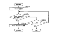
- FIG. 10 shows a procedure of operation of the receiving terminal 200 in the connection process.
- control unit 230 transmits the identification information that identifies the communication device 210 to the communication device 140 of the transmission terminal 100 (step S2000).
- step S2000 the communication device 210 waits for receiving the connection request.
- the connection request is transmitted from the communication device 140
- the communication device 210 receives the connection request.
- the control unit 230 determines whether or not the connection request has been received (step S2005). For example, in step S2005, the control unit 230 determines whether or not the connection request has been received within a predetermined time from the timing at which the identification information is transmitted.
- step S2010 the control unit 230 transmits the connection confirmation to the communication device 140 by using the communication device 210 (step S2010).
- step S2010 the process shown in FIG. 10 is completed, and step S205 shown in FIG. 6 is executed.
- the connection between the communication device 140 and the communication device 210 is established.
- the communication device 140 and the communication device 210 can carry out image communication.
- step S2015 determines whether or not a timeout has occurred. For example, the control unit 230 determines whether or not the time elapsed from the timing at which the identification information is transmitted in step S2000 exceeds a predetermined time. If the time exceeds a predetermined time, the control unit 230 determines that a time-out has occurred. If the time does not exceed the predetermined time, the control unit 230 determines that a timeout has not occurred.
- step S2015 determines that a timeout has occurred in step S2015.
- the processes shown in FIGS. 10 and 6 end. If the control unit 230 determines in step S2015 that no timeout has occurred, step S2005 is executed.
- the communication device 210 transmits the identification information of the communication device 210 to the communication device 140.
- the communication devices of the receiving terminal 200 other than the communication device 210 communicate the identification information of the communication device 210. It may be transmitted to the communication device of the transmission terminal 100 other than the machine 140. That is, the receiving terminal 200 may transmit the identification information to the transmitting terminal 100 by using a communication device other than the communication device 210 used for receiving the image.
- the period of the vertical synchronization signal (imaging Vsync) is adjusted.
- the period of the horizontal synchronization signal may be adjusted by using the same method as the above method.
- the communication method of each aspect of the present invention has a calculation step, a first adjustment step, and a second adjustment step.
- the processor 132 calculates an adjustment value indicating the difference between the imaging cycle and the display cycle in the calculation step (step S1615).
- the processor 132 adjusts the signal generator 131 based on the adjustment value in the first adjustment step (step S1625) to match the imaging cycle and the display cycle.
- the connection history in which the adjustment information and the identification information are associated with each other is recorded on the recording medium 150.
- the adjustment information directly or indirectly indicates the adjustment value.
- the identification information identifies one of the communication device 140 and the communication device 210.
- the processor 132 When the communication device 140 and the communication device 210 are reconnected to each other, the processor 132 has a second adjustment step (step) if the identification information corresponding to one of the communication device 140 and the communication device 210 is recorded on the recording medium 150.
- the signal generator 131 is adjusted based on the adjustment value indicated by the adjustment information associated with the identification information in the connection history.
- the communication method of each aspect of the present invention does not need to have steps other than the calculation step, the first adjustment step, and the second adjustment step.
- the processor 132 determines whether or not the identification information of the communication device 210 is recorded on the recording medium 150.
- the processor 132 adjusts the signal generator 131 based on the adjustment value indicated by the adjustment information associated with the identification information in the connection history. In this case, the processor 132 does not need to execute step S160 shown in FIG. Therefore, the communication system 10 can match the cycles of the synchronization signals of the transmitting terminal 100 and the receiving terminal 200 in a short time.
- step S110 When step S110 is executed, the cycle of the imaging Vsync and the cycle of the display Vsync match in a short time. After the step S120 shown in FIG. 4 is executed, the state in which the imaging Vsync and the display Vsync are synchronized with each other is likely to be maintained. Therefore, the communication system 10 can avoid the loss of video data.
- FIG. 2 (Modified example of the first embodiment) A first modification of the first embodiment of the present invention will be described.
- the transmission terminal 100 shown in FIG. 2 is changed to the transmission terminal 100a shown in FIG.
- FIG. 11 shows the configuration of the transmission terminal 100a. The description of the same configuration as that shown in FIG. 2 will be omitted.
- the control unit 130 shown in FIG. 2 is changed to the control unit 130a.
- the processor 132 shown in FIG. 2 is changed to the processor 132a.
- the processor 132a has functions as a cycle measuring unit 133 and a cycle adjusting unit 134.
- the processor 132a does not have a function as the adjustment value detection unit 135 shown in FIG.
- the transmission terminal 100a does not have the recording medium 150 shown in FIG.
- the communication device 140 transmits identification information for identifying the communication device 140 to the communication device 210.
- the identification information is the MAC address of the communication device 140.
- the information that identifies the transmitting terminal 100a may be used as the identification information of the communication device 140.
- the identification information may be a serial number that can uniquely identify the transmitting terminal 100a.
- the receiving terminal 200 shown in FIG. 3 is changed to the receiving terminal 200a shown in FIG.
- FIG. 12 shows the configuration of the receiving terminal 200a. The description of the same configuration as that shown in FIG. 3 will be omitted.
- the receiving terminal 200a has a recording medium 250.
- the recording medium 250 is a volatile or non-volatile recording medium.
- the recording medium 250 is at least one of RAM, DRAM, SRAM, EEPROM, FRAM®, flash memory, and a hard disk drive.
- the recording medium 250 stores the connection history.
- the adjustment value calculated by the periodic measurement unit 133 and the identification information for identifying the communication device 140 are associated with each other.
- control unit 230 shown in FIG. 3 is changed to the control unit 230a.
- the control unit 230a has a signal generator 231 and a processor 232.
- the processor 232 has a function as an adjustment value detection unit 235.
- the adjustment value detection unit 235 determines whether or not the identification information received from the communication device 140 is included in the connection history recorded on the recording medium 250. To do.
- the adjustment value detection unit 235 detects an adjustment value that can be used for adjusting the imaging cycle.
- the processor 232 may read the program and execute the read program.
- the program contains instructions that specify the operation of processor 232. That is, the function of the processor 232 may be realized by software.
- the program is realized in the same manner as the program that realizes the function of the processor 132.
- the processor 232 transmits information to the transmission terminal 100a by using the communication device 210. Specifically, the processor 232 controls the communication device 210 so that the information is transmitted to the transmission terminal 100a. That is, the processor 232 causes the communication device 210 to transmit the information for the transmission terminal 100a. As a result, the communication device 210 transmits the information to the transmission terminal 100a.
- the processor 232 receives an image or information from the transmitting terminal 100a by using the communication device 210. Specifically, the processor 232 controls the communication device 210 so that the image or information is received from the transmission terminal 100a. That is, the processor 232 causes the communication device 140 to receive the image or information from the transmission terminal 100a. As a result, the communication device 210 receives the image or information from the transmission terminal 100a.
- the processor 232 acquires identification information for identifying the communication device 140.
- the communication device 140 transmits the identification information to the communication device 210.
- the processor 232 receives the identification information from the communication device 140 by using the communication device 210.
- the processor 132 uses the communication device 140 to transmit the adjustment information indicating the adjustment value to the communication device 210.
- the processor 232 receives the adjustment information from the communication device 140 by using the communication device 210.
- the processor 232 records the connection history in which the adjustment information and the identification information are associated with each other on the recording medium 250.
- the processor 232 determines whether or not the newly acquired identification information is the same as the identification information recorded on the recording medium 250. When the processor 232 determines that the newly acquired identification information is the same as the identification information recorded on the recording medium 250, the processor 232 transfers the adjustment information associated with the identification information in the connection history to the communication device 210. By using it, it is transmitted to the communication device 140.
- the processor 132 receives the adjustment information from the communication device 210 by using the communication device 140.
- the processor 132 adjusts the signal generator 131 based on the adjustment information received from the communication device 210.
- FIG. 13 shows a procedure for operating the transmitting terminal 100a. The description of the same process as that shown in FIG. 4 will be omitted.
- the processor 132a executes the connection process (step S100a).
- the connection process is the same as the connection process shown in FIG. 7, except for step S1000 shown in FIG. 7.
- the processor 132a transmits the identification information of the communication device 140 to the communication device 210 of the receiving terminal 200a by using the communication device 140.
- the communication device 210 of the receiving terminal 200a transmits the adjusted value to the communication device 140.
- the communication device 140 receives the adjustment value.
- the processor 132a determines whether or not the adjustment value has been received (step S105a). For example, in step S105a, the processor 132a determines whether or not the adjustment value is received within a predetermined time from the timing when the connection process is executed. If the processor 132a determines that the adjustment value has been received in step S105a, step S110 is executed.
- step S110 the processor 132a adjusts the cycle of the imaging Vsync by applying the adjustment value received from the communication device 210 to the signal generator 131. If the processor 132a determines in step S105a that the adjustment value has not been received, step S140 is executed.
- step S160 the processor 132a transmits the adjustment value calculated in step S160 to the communication device 210 by using the communication device 140 (step S165a). After step S165a, step S135 is executed.
- the communication device 140 transmits the identification information to the communication device 210.
- the communication method of the identification information is not limited to this.
- the transmitting terminal 100a may have two or more communicators including the communicator 140, and the receiving terminal 200a may have two or more communicators including the communicator 210.
- the communication device of the transmission terminal 100a other than the communication device 140 may transmit the identification information of the communication device 210 to the communication device of the reception terminal 200a other than the communication device 210. That is, the transmitting terminal 100a may transmit the identification information to the receiving terminal 200a by using a communication device other than the communication device 140 used for transmitting the image.
- the communication device 140 receives the adjustment value from the communication device 210 in step S105a.
- the communication method of the adjusted value is not limited to this.
- the communicator of the transmitting terminal 100a other than the communicator 140 sets the adjustment value in step S105a. It may be received from the communication device of the receiving terminal 200a other than 210. That is, the transmitting terminal 100a may receive the adjustment value from the receiving terminal 200a by using a communication device other than the communication device 140 used for transmitting the image.
- the communication device 140 transmits the adjustment value to the communication device 210 in step S165a.
- the communication method of the adjusted value is not limited to this.
- the communicator of the transmitting terminal 100a other than the communicator 140 sets the adjustment value in step S165a. It may be transmitted to the communication device of the receiving terminal 200a other than 210. That is, the transmitting terminal 100a may transmit the adjusted value to the receiving terminal 200a by using a communication device other than the communication device 140 used for transmitting the image.
- FIG. 14 shows a procedure for operating the receiving terminal 200a. The description of the same process as that shown in FIG. 6 will be omitted.
- Processor 232 executes the connection process (step S200a).
- the connection process is the same as the connection process shown in FIG. 10, except for step S2000 shown in FIG.
- the processor 232 receives the identification information of the communication device 140 of the transmission terminal 100a from the communication device 140 by using the communication device 210.
- the processor 232 determines whether or not the identification information received from the communication device 140 is included in the connection history recorded on the recording medium 250. As a result, the processor 232 determines whether or not the adjustment value is included in the connection history (step S230). When the communication device 140 and the communication device 210 are connected to each other for the first time, the adjustment value and the identification information of the communication device 140 are not included in the connection history. If the identification information is not included in the connection history, the processor 132 determines that the adjustment value is not included in the connection history.
- the adjustment value and the identification information of the communication device 140 are included in the connection history.
- the processor 132 determines that the adjustment value is included in the connection history.
- step S230 When the processor 232 determines in step S230 that the adjustment value is included in the connection history, the processor 232 reads the adjustment value associated with the identification information received from the communication device 140 in the connection history from the recording medium 250. .. The processor 232 transmits the adjustment value to the communication device 140 by using the communication device 210 (step S231). After step S231, step S205 is executed. If the processor 232 determines in step S230 that the adjustment value is not included in the connection history, step S205 is executed.
- step S215 processor 232 determines whether an adjustment value has been received (step S232). If the processor 232 determines in step S232 that the adjustment value has not been received, step S220 is executed.
- step S232 When the processor 232 determines that the adjustment value has been received in step S232, the processor 232 associates the adjustment value received from the communication device 140 with the identification information of the communication device 140.
- the processor 232 records the connection history including the adjustment value and the identification information on the recording medium 250 (step S233). After step S233, step S220 is executed.
- the communication device 210 receives the identification information of the communication device 140 from the communication device 140.
- the communication devices of the receiving terminal 200a other than the communication device 210 communicate the identification information of the communication device 140. It may be received from a communication device of the transmission terminal 100a other than the machine 140. That is, the receiving terminal 200a may receive the identification information from the transmitting terminal 100a by using a communication device other than the communication device 210 used for receiving the image.
- the communication device 210 transmits the adjustment value to the communication device 140 in step S231.
- the communicator of the receiving terminal 200a other than the communicator 210 sets the adjustment value in step S231. It may be transmitted to the communication device of the transmission terminal 100a other than 140. That is, the receiving terminal 200a may transmit the adjusted value to the transmitting terminal 100a by using a communication device other than the communication device 210 used for receiving the image.
- the communication device 210 receives the adjustment value from the communication device 140 in step S232.
- the communicator of the receiving terminal 200a other than the communicator 210 sets the adjustment value in step S232. It may be received from a communication device of a transmitting terminal 100a other than 140. That is, the receiving terminal 200a may receive the adjusted value from the transmitting terminal 100a by using a communication device other than the communication device 210 used for receiving the image.
- the timings of the transmission of the adjustment value in step S165a and the reception of the adjustment value in step S232 are not limited to the timings shown in FIGS. 13 and 14.
- communication of adjustment values may be carried out on a regular basis. Communication of the adjusted value may be performed after a predetermined time has elapsed from the timing at which the period of the imaging Vsync of the transmitting terminal 100a is adjusted. After being instructed to end the imaging, the adjustment value communication may be performed. The communication of the adjusted value may be performed before the connection between the communication device 140 and the communication device 210 is disconnected.
- the processor 232 of the receiving terminal 200a determines whether or not the identification information of the communication device 140 is recorded on the recording medium 250. to decide.
- the processor 232 uses the communication device 210 to transmit the adjustment information associated with the identification information in the connection history to the communication device 140.
- the processor 132a of the transmission terminal 100a adjusts the signal generator 131 based on the adjustment value indicated by the adjustment information received from the communication device 210. In this case, the processor 132a does not need to execute step S160 shown in FIG.
- the communication system 10 can match the cycles of the synchronization signals of the transmitting terminal 100a and the receiving terminal 200a in a short time.
- the source clock of the transmitting terminal 100a and the source clock of the receiving terminal 200a may change due to temperature and aging. Therefore, the periodic adjustment may be performed between the transmission terminal 100a and the reception terminal 200a at predetermined intervals, and the adjustment value may be updated by rewriting the adjustment value recorded on the recording medium 250. Even when the source clock of the transmitting terminal 100a or the receiving terminal 200a changes, the cycle adjustment operation described in the first embodiment becomes possible.
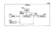
- the transmission terminal 100b has a temperature sensor 160 (first temperature sensor) in addition to the configuration shown in FIG.
- the temperature sensor 160 has a thermistor.
- the temperature sensor 160 is arranged in the vicinity of the oscillator 120.
- the temperature sensor 160 may come into contact with the oscillator 120.
- the temperature sensor 160 measures the temperature of the oscillator 120 and outputs a signal indicating the temperature to the processor 132.
- the receiving terminal 200 shown in FIG. 3 is changed to the receiving terminal 200b shown in FIG.
- FIG. 16 shows the configuration of the receiving terminal 200b. The description of the same configuration as that shown in FIG. 3 will be omitted.
- the receiving terminal 200b has a temperature sensor 260 (second temperature sensor) in addition to the configuration shown in FIG.
- the temperature sensor 260 has a thermistor.
- the temperature sensor 260 is arranged in the vicinity of the oscillator 220.
- the temperature sensor 260 may come into contact with the oscillator 220.
- the temperature sensor 260 measures the temperature of the oscillator 220 and outputs a signal indicating the temperature to the control unit 230.
- the processor 132 of the transmission terminal 100b acquires temperature information indicating the temperature measured by the temperature sensor 260 of the reception terminal 200b.
- the communication device 210 transmits the temperature information to the communication device 140.
- the processor 132 receives the temperature information from the communication device 210 by using the communication device 140.
- the processor 132 calculates the adjustment value
- the processor 132 records the connection history on the recording medium 150. In the connection history, the temperature measured by the temperature sensor 160, the temperature measured by the temperature sensor 260, the adjustment information indicating the adjustment value, and the identification information for identifying the communication device 210 are associated with each other.
- the processor 132 determines whether or not to correct the adjustment value.
- the processor 132 determines that the adjustment value is corrected, the processor 132 sets the adjustment value indicated by the adjustment information associated with the identification information in the connection history as the first synchronization signal (imaging Vsync) and the second synchronization signal (display Vsync). ) Is corrected based on the temperature characteristics of each source clock. The processor 132 adjusts the signal generator 131 based on the corrected adjustment value.
- FIG. 17 is a graph showing the relationship between the temperature and the oscillation period of the source vibration clock.
- the horizontal axis in FIG. 17 indicates the temperature [° C.]
- the vertical axis in FIG. 17 indicates the oscillation period [ppm] of the source clock.
- the graph in FIG. 17 shows the temperature characteristics of the source clock. For example, when the temperature changes from 25 ° C to 50 ° C, a deviation of ⁇ 2.0 ppm occurs with respect to the oscillation period at 25 ° C.
- the temperature characteristics of the oscillation cycle of the source vibration clock may differ between the oscillator 120 and the oscillator 220.
- a table showing the relationship between the temperature of each of the oscillator 120 and the oscillator 220 and the oscillation period of the source vibration clock is recorded on the recording medium 150.
- FIG. 18 shows an example of the connection history recorded on the recording medium 150.
- the identification information, the adjustment value, the temperature of the transmitting terminal 100b, and the temperature of the receiving terminal 200b are associated with each other.
- the temperature of the transmitting terminal 100b is the temperature measured by the temperature sensor 160.
- the temperature of the receiving terminal 200b is the temperature measured by the temperature sensor 260.
- FIG. 19 shows a procedure for operating the transmitting terminal 100b. The description of the same process as that shown in FIG. 4 will be omitted.
- step S105 when the processor 132 determines that the adjustment value is included in the connection history, the processor 132 acquires the temperature from the temperature sensor 160 (step S170). After step S170, step S115 is executed.
- step S115 the processor 132 receives the synchronization packet from the communication device 210 by using the communication device 140.
- the synchronization packet contains temperature information indicating the temperature measured by the temperature sensor 260 of the receiving terminal 200b.
- processor 132 adjusts the temperature based on the temperature measured by each of the temperature sensor 160 and the temperature sensor 260 and the temperature associated with the identification information received from the communicator 210 in the connection history. It is determined whether or not correction is necessary (step S171).
- the processor 132 calculates the difference in the oscillation cycle generated based on the difference between the temperature in the past connection and the temperature in the current connection for each terminal. Specifically, the processor 132 uses the temperature of the transmission terminal 100b in the connection history, the temperature acquired in step S170, and the temperature characteristic of the oscillation cycle of the source vibration clock in the oscillator 120. For example, the temperature characteristic of the oscillation cycle of the source vibration clock in the oscillator 120 is the same as the graph shown in FIG. The processor 132 calculates the difference ⁇ CNT_A_T of the oscillation period of the oscillator clock in the oscillator 120.
- the temperature of the transmitting terminal 100b in the connection history is 25 ° C. and the temperature acquired in step S170 is 30 ° C.
- the oscillation cycle at a temperature of 25 ° C. is 0 ppm
- the oscillation cycle at a temperature of 30 ° C. is ⁇ 1.0 ppm.
- the difference ⁇ CNT_A_T is ⁇ 1.0 ppm.
- the processor 132 executes the same process as the above process by using the information of the receiving terminal 200b. Specifically, the processor 132 uses the temperature of the receiving terminal 200b in the connection history, the temperature indicated by the temperature information included in the synchronization packet, and the temperature characteristic of the oscillation cycle of the source clock in the oscillator 220. The processor 132 calculates the difference ⁇ CNT_B_T of the oscillation period of the oscillator clock in the oscillator 220.
- the processor 132 calculates the difference ⁇ CNT ( ⁇ CNT_A_T- ⁇ CNT_B_T) of the difference ⁇ CNT_A_T and the difference ⁇ CNT_B_T.
- the processor 132 determines whether or not the absolute value of the difference ⁇ CNT is larger than a predetermined value. When the absolute value of the difference ⁇ CNT is larger than the predetermined value, the processor 132 determines that the adjustment value needs to be corrected. When the absolute value of the difference ⁇ CNT is equal to or less than a predetermined value, the processor 132 determines that the adjustment value does not need to be corrected.
- step S110 is executed.
- the processor 132 determines in step S171 that the adjustment value needs to be corrected, the processor 132 reads the adjustment value associated with the identification information in the connection history from the recording medium 150 and corrects the adjustment value.
- the processor 132 adjusts the period of the imaging Vsync by applying the corrected adjustment value to the signal generator 131 (step S172). After step S172, step S120 is executed.
- the details of the process executed by the processor 132 in step S172 will be described.
- the processor 132 reads the adjustment value associated with the identification information in the connection history from the recording medium 150.
- the processor 132 corrects the adjustment value based on the difference ⁇ CNT. For example, when the difference ⁇ CNT is +10 ppm, the oscillation cycle of the source clock in the oscillator 120 is longer than the oscillation cycle of the source clock in the oscillator 220. In this case, the processor 132 reduces the adjustment value (positive adjustment value or negative adjustment value) by a value corresponding to +10 ppm in order to shorten the period of the imaging Vsync.
- the processor 132 increases the adjustment value (positive adjustment value or negative adjustment value) by a value corresponding to ⁇ 10 ppm in order to lengthen the period of the imaging Vsync.
- the processor 132 adjusts the period of the imaging Vsync based on the corrected adjustment value.
- the method of adjusting the cycle of the imaging Vsync is the same as the method of adjusting the cycle of the imaging Vsync in step S110.
- step S160 the processor 132 acquires the temperature from the temperature sensor 160 (step S173). After step S173, the processor 132 correlates the identification information of the communication device 210, the adjustment value calculated in step S160, the temperature acquired in step S173, and the temperature of the receiving terminal 200b with each other. The temperature of the receiving terminal 200b is indicated by the temperature information included in the synchronization packet received in step S140. The processor 132 records the connection history including the identification information, the adjustment value, and the temperature of each terminal on the recording medium 150 (step S165b). After step S165b, step S135 is executed.
- the communication device 140 receives the temperature information from the communication device 210.
- the communication method of temperature information is not limited to this.
- the transmitting terminal 100b may have two or more communicators including the communicator 140, and the receiving terminal 200b may have two or more communicators including the communicator 210.
- the communication device of the transmission terminal 100b other than the communication device 140 may receive the temperature information from the communication device of the reception terminal 200b other than the communication device 210. That is, the transmitting terminal 100b may receive the temperature information from the receiving terminal 200b by using a communication device other than the communication device 140 used for transmitting the image.
- FIG. 20 shows a procedure for operating the receiving terminal 200b. The description of the same process as that shown in FIG. 6 will be omitted.
- step S200 the control unit 230 acquires the temperature from the temperature sensor 260 (step S240).
- step S240 step S205 is executed.
- the communication device 210 transmits the synchronization packet to the communication device 140 of the transmission terminal 100b in step S205.
- the synchronization packet contains temperature information indicating the temperature acquired in step S240.
- the communication device 210 transmits the temperature information to the communication device 140.
- the communication device of the receiving terminal 200b other than the communication device 210 sends the temperature information to the communication device other than the communication device 140. It may be transmitted to the communication device of the transmission terminal 100b. That is, the receiving terminal 200b may transmit the temperature information to the transmitting terminal 100b by using a communication device other than the communication device 210 used for receiving the image.
- the temperature sensor 160 and the temperature sensor 260 measure the temperature on a regular basis. In the above example, the temperature sensor 160 and the temperature sensor 260 measure the temperature every frame period. The temperature sensor 160 and the temperature sensor 260 may measure the temperature at intervals shorter than one frame period or at intervals longer than one frame period.
- the processor 132 corrects the adjustment value based on the temperature characteristic of the source clock, and adjusts the signal generator 131 based on the corrected adjustment value. Therefore, even when the oscillation cycle of the source vibration clock changes according to the temperature, the communication system 10 can match the cycles of the synchronization signals of the transmitting terminal 100b and the receiving terminal 200b in a short time.
- FIG. 21 shows the configuration of the transmission terminal 100c. The description of the same configuration as that shown in FIG. 2 will be omitted.
- the radio unit 140c has one or more radio modules (first radio module).
- the radio unit 140c has a radio module 141 and a radio module 142.
- Each radio module has a unique MAC address for each radio module.
- the receiving terminal 200 shown in FIG. 3 is changed to the receiving terminal 200c shown in FIG. 22.
- FIG. 22 shows the configuration of the receiving terminal 200c. The description of the same configuration as that shown in FIG. 3 will be omitted.
- the radio unit 210c has two or more radio modules (second radio modules).
- the radio unit 210c has a radio module 211, a radio module 212, and a radio module 213.
- Each radio module has a unique MAC address for each radio module.
- Each wireless module of the wireless unit 140c and each wireless module of the wireless unit 210c carry out wireless communication.
- the identification information in the third embodiment is the MAC address of the wireless module included in the wireless unit 210c.
- the identification information of each of the wireless module 211, the wireless module 212, and the wireless module 213 is associated with the adjustment information indicating the adjustment value.
- each wireless module is a wireless LAN represented by 802.11a / b / g / n / ac and the like.
- Each radio module of the radio unit 210c functions as an access point (AP) and initiates a connection using channels independent of each other. For example, a channel belonging to any one of W52, W53, and W56 is used.
- Each radio module of the radio unit 140c functions as a station (STA).
- One of the radio module 141 and the radio module 142 uses the main channel to transmit images, and the other of the radio module 141 and the radio module 142 uses the subchannel to establish only the link connection.
- the number of wireless modules of the wireless unit 140c is not limited to two, and the number of wireless modules of the wireless unit 210c is not limited to three.
- the radio unit 140c may have three or more radio modules.
- the radio unit 210c may have two radio modules, or may have four or more radio modules. When the radio unit 140c has one radio module and the radio unit 210c has one radio module, the same process as in the first embodiment is executed.
- FIG. 23 shows a procedure for operating the transmitting terminal 100c. The description of the same process as that shown in FIG. 4 will be omitted.
- the processor 132 executes the connection process (step S100c).
- the connection process in the third embodiment is different from the connection process in the first embodiment.
- the details of the connection process (step S100c) executed in the transmission terminal 100c will be described.
- FIG. 24 shows a procedure for operating the transmitting terminal 100c in the connection process.
- the radio unit 140c stands by for receiving the Beacon transmitted from one radio module of the radio unit 210c of the receiving terminal 200c.
- the Beacon is transmitted from the radio unit 210c
- one radio module of the radio unit 140c receives the Beacon (step S1000c).
- the processor 132 transmits a connection request (Probe Request) to one radio module of the radio unit 210c by using one radio module of the radio unit 140c (step S1005c).
- One radio module of the radio unit 210c receives a connection request and transmits a connection confirmation (Probe Response) to one radio module of the radio unit 140c.
- step S1010c determines whether or not the connection confirmation has been received. For example, in step S1010c, the processor 132 determines whether or not the connection confirmation has been received within a predetermined time from the timing when the connection request is transmitted.
- step S1010c When the processor 132 determines that the connection confirmation has been received in step S1010c, the process shown in FIG. 24 ends, and step S180 shown in FIG. 23 is executed. In this case, a connection is established between one radio module of the radio unit 140c and one radio module of the radio unit 210c.
- the radio unit 140c and the radio unit 210c can perform image communication.
- the wireless module 141 and the wireless module 142 of the wireless unit 140c may execute the connection process independently of each other.
- the connection relationship between the wireless unit 140c and the wireless unit 210c is arbitrary.
- the radio module 141 is connected to any one of the three radio modules of the radio unit 210c, and the radio module 142 is connected to any one of the three radio modules of the radio unit 210c.
- the radio module 141 and the radio module 142 do not connect to the same radio module at the same time.
- Step S1015 is the same as step S1015 shown in FIG.
- step S1015 When the processor 132 determines that a timeout has occurred in step S1015, the processes shown in FIGS. 24 and 23 are completed. If the processor 132 determines in step S1015 that no timeout has occurred, step S1005c is executed.
- step S1010c shown in FIG. 24 when the processor 132 determines that the connection confirmation has been received, one radio module of the radio unit 140c is the MAC address of one radio module of the radio unit 210c used for communication of the adjusted value. Is received from one radio module of the radio unit 210c.
- the processor 132 acquires the received MAC address from the radio unit 140c (step S180).
- the wireless module used for image communication in step S155 and the wireless module used for MAC address communication in step S180 may be the same or different.
- step S105 is executed.
- the processor 132 uses the MAC address as the identification information in step S105.
- the processor 132 transmits a MAC address request to one radio module of the radio unit 210c by using one radio module of the radio unit 140c (step S181).
- the MAC address request indicates a request for all MAC addresses of the three radio modules of the radio unit 210c.
- the wireless module used for image communication in step S155 and the wireless module used for MAC address request communication in step S181 may be the same or different.
- one radio module of the radio unit 140c receives all the MAC addresses of the three radio modules of the radio unit 210c from one radio module of the radio unit 210c.
- the processor 132 acquires the received MAC address from the radio unit 140c (step S182).
- the wireless module used in step S181 and the wireless module used in step S182 are the same.
- step S182 the processor 132 associates the adjustment value calculated in step S160 with all the MAC addresses of the three radio modules of the radio unit 210c.
- the processor 132 records the connection history including the adjustment value and the MAC address on the recording medium 150 (step S165c). After step S165c, step S135 is executed.
- FIG. 25 shows an example of the connection history recorded on the recording medium 150.
- the three MAC addresses and adjustment values are associated with each other.
- the three MAC addresses are identification information of the three wireless modules of the wireless unit 210c.
- the first wireless module and the second wireless module may be different from each other.
- the first radio module is one radio module of the radio unit 210c that was used when the radio unit 140c and the radio unit 210c were connected to each other for the first time.
- the second radio module is one radio module of the radio unit 210c that was used when the radio unit 140c and the radio unit 210c were then connected to each other.
- the processor 132 can use the adjustment value associated with its MAC address.
- FIG. 26 shows a procedure for operating the receiving terminal 200c. The description of the same process as that shown in FIG. 6 will be omitted.
- the control unit 230 executes the connection process (step S200c).
- the connection process in the third embodiment is different from the connection process in the first embodiment.
- the details of the connection process (step S200c) executed in the receiving terminal 200c will be described.
- FIG. 27 shows a procedure for operating the receiving terminal 200c in the connection process.
- the control unit 230 transmits the Beacon to one radio module of the radio unit 140c of the transmission terminal 100c by using one radio module of the radio unit 210c (step S2000c).
- one wireless module of the wireless unit 210c waits for receiving a connection request (Probe Request).
- a connection request is transmitted from one radio module of the radio unit 140c
- one radio module of the radio unit 210c receives the connection request.
- the control unit 230 determines whether or not the connection request has been received (step S2005c). For example, in step S2005c, the control unit 230 determines whether or not the connection request is received within a predetermined time from the timing when the Beacon is transmitted.
- the control unit 230 uses one wireless module of the wireless unit 210c to perform a connection confirmation (Probe Response) to one of the wireless units 140c. It is transmitted to the wireless module (step S2010c).
- step S2010c is executed, the process shown in FIG. 26 is completed, and step S250 shown in FIG. 25 is executed.
- a connection is established between one radio module of the radio unit 140c and one radio module of the radio unit 210c.
- the radio unit 140c and the radio unit 210c can perform image communication.
- the wireless module 211, the wireless module 212, and the wireless module 213 of the wireless unit 210c may execute the connection process independently of each other.
- Step S2015 is the same as step S2015 shown in FIG.
- step S2015 determines that a timeout has occurred in step S2015, the processes shown in FIGS. 26 and 25 are completed. If the control unit 230 determines in step S2015 that no timeout has occurred, step S2005c is executed.
- step S2010c the control unit 230 uses one radio module of the radio unit 210c to set the MAC address of one radio module of the radio unit 210c used for communication of the adjusted value to one of the radio units 140c. It is transmitted to the wireless module (step S250).
- the wireless module used for image communication in step S210 and the wireless module used for MAC address communication in step S250 may be the same or different.
- step S205 is executed.
- step S215 the control unit 230 determines whether or not the MAC address request has been received (step S251). If the control unit 230 determines in step S251 that the MAC address request has not been received, step S220 is executed.
- the wireless module used for image communication in step S210 and the wireless module used for MAC address request communication in step S251 may be the same or different.
- step S251 When the control unit 230 determines in step S251 that the MAC address request has been received, the control unit 230 uses one radio module of the radio unit 210c to use all the MACs of the three radio modules of the radio unit 210c.
- the address is transmitted to one radio module of the radio unit 140c (step S252).
- the wireless module used in step S251 and the wireless module used in step S252 are the same.
- step S220 is executed.
- the data area of the sync packet may be used to send the MAC address.
- the communication system 10 may have an RFID (radio frequency identifier) tag and an RFID reader / writer.
- the receiving terminal 200c may have an RFID reader / writer
- the transmitting terminal 100c may have an RFID tag.
- An example of using an RFID tag and an RFID reader / writer for MAC address communication will be described.
- the RFID tag of the transmission terminal 100c can communicate with the processor 132.
- the RFID reader / writer of the receiving terminal 200c writes the MAC addresses of all the wireless modules of the receiving terminal 200c on the RFID tag of the transmitting terminal 100c.
- the RFID tag of the transmitting terminal 100c outputs an interrupt signal to the processor 132.
- the processor 132 reads the MAC address written in the RFID tag.
- the processor 132 can determine whether or not the MAC address written in the RFID tag is included in the connection history recorded in the recording medium 150. Therefore, before the wireless module of the wireless unit 140c and the wireless module of the wireless unit 210c are connected to each other, the processor 132 can determine whether or not the adjustment value associated with the MAC address is included in the connection history. ..
- the processor 132 may notify the user that the cycle adjustment needs to be performed by using a display means such as an LED. Before the wireless module of the wireless unit 140c and the wireless module of the wireless unit 210c are connected to each other, the user can know that the video data may be lost.
- the identification information may be a combination of SSID and passphrase used in the wireless connection.
- the transmitting terminal 100c may have the temperature sensor 160 shown in FIG. 15, and the receiving terminal 200c may have the temperature sensor 260 shown in FIG.
- the connection history recorded on the recording medium 150 includes the temperature measured by each of the temperature sensor 160 and the temperature sensor 260, the adjustment information indicating the adjustment value, and the identification information for identifying the radio module of the radio unit 210c. Good.
- Processor 132 may correct the adjustment value by using the method described in the second embodiment.
- the processor 132 determines whether or not the MAC address of the radio module of the radio unit 210c is recorded on the recording medium 150.
- the processor 132 adjusts the signal generator 131 based on the adjustment value indicated by the adjustment information associated with the MAC address in the connection history. In this case, the processor 132 does not need to execute step S160 shown in FIG. Therefore, the communication system 10 can match the cycles of the synchronization signals of the transmitting terminal 100c and the receiving terminal 200c in a short time.
- the MAC addresses of the wireless module 211, the wireless module 212, and the wireless module 213 are associated with the adjustment information indicating one adjustment value. It is not necessary to record the combination of the MAC address of the wireless module and the adjustment information on the recording medium 150 for each wireless module. Therefore, the storage capacity of the recording medium 150 can be reduced, and the processing time for recording the information on the recording medium 150 can be shortened.
- a fourth embodiment of the present invention will be described.
- the fourth embodiment an example of a communication system having one transmitting terminal and two or more receiving terminals will be described.
- the imaging Vsync of the transmitting terminal cannot be synchronized with the display Vsync of all the receiving terminals. Therefore, each receiving terminal synchronizes the display Vsync with the imaging Vsync of the transmitting terminal.
- FIG. 28 shows the configuration of the communication system 10d according to the fourth embodiment.
- the communication system 10d shown in FIG. 28 has one transmitting terminal 100d and two or more receiving terminals 200d.
- FIG. 29 shows the configuration of the transmitting terminal 100d. The description of the same configuration as that shown in FIG. 2 will be omitted.
- control unit 130 shown in FIG. 2 is changed to the control unit 130d.
- the control unit 130d does not have the processor 132 shown in FIG.
- the transmitting terminal 100d does not have the recording medium 150 shown in FIG.
- FIG. 30 shows the configuration of the receiving terminal 200d. The description of the same configuration as that shown in FIG. 3 will be omitted.
- the receiving terminal 200d has a recording medium 250 for storing the connection history.
- the adjustment value for adjusting the cycle of the display Vsync and the identification information for identifying the communication device 140 are associated with each other.
- control unit 230 shown in FIG. 3 is changed to the control unit 230d.
- the control unit 230d includes a signal generator 231 and a processor 232d.
- the outline function of the processor 232d will be described. After the communication device 140 and the communication device 210 are connected to each other, the processor 232d calculates an adjustment value indicating the difference between the imaging cycle and the display cycle. The processor 232d adjusts the signal generator 231 based on the adjustment value to match the imaging cycle and the display cycle. The connection history in which the adjustment information indicating the adjustment value and the identification information for identifying the communication device 140 are associated with each other is recorded on the recording medium 250. When the communication device 140 and the communication device 210 are reconnected to each other, if the identification information for identifying the communication device 140 is recorded on the recording medium 250, the processor 232 will display the adjustment information associated with the identification information in the connection history. The signal generator 231 is adjusted based on the adjustment value shown.
- the processor 232d acquires identification information that identifies the communicator 140.
- the communication device 140 transmits the identification information to the communication device 210.
- the processor 232d receives the identification information from the communication device 140 by using the communication device 210.
- the processor 232d calculates the adjustment value
- the processor 232d records the connection history in which the adjustment information and the identification information are associated with each other on the recording medium 250.
- the processor 232d determines whether or not the newly acquired identification information is the same as the identification information recorded on the recording medium 250. If the processor 232d determines that the newly acquired identification information is the same as the identification information recorded on the recording medium 250, the processor 232d is based on the adjustment value indicated by the adjustment information associated with the identification information in the connection history. Adjust the signal generator 231.
- the processor 232d has functions as a cycle measurement unit 233, a cycle adjustment unit 234, and an adjustment value detection unit 235.
- the cycle measurement unit 233 measures the difference between the imaging cycle and the display cycle, and calculates an adjustment value indicating the difference.
- the cycle adjustment unit 234 adjusts the signal generator 231 based on the adjustment value. The signal generator 231 is adjusted so that the cycle (display cycle) of the display Vsync generated by the signal generator 231 coincides with the imaging cycle.
- the adjustment value detection unit 235 determines whether or not the identification information received from the communication device 140 is included in the connection history recorded on the recording medium 250. To do. When the identification information received from the communication device 140 is included in the connection history, the adjustment value detection unit 235 detects an adjustment value that can be used for adjusting the display cycle. When the adjustment value detection unit 235 determines that the identification information received from the communication device 140 is included in the connection history, the cycle adjustment unit 234 signals based on the adjustment value associated with the identification information in the connection history. Adjust the generator 231.
- the signal generator 231 has a cycle counter that defines the cycle of the display Vsync. By adjusting the value measured by the cycle counter of the signal generator 231, the cycle of the display Vsync is adjusted.
- FIG. 31 shows a procedure for operating the transmitting terminal 100d. The description of the same process as that shown in FIG. 4 will be omitted.
- the control unit 130d executes the connection process (step S100d).
- the connection process is the same as the connection process shown in FIG. 7, except for step S1000 shown in FIG. 7.
- the communication device 140 transmits the identification information of the communication device 140 to the communication device 210 of the receiving terminal 200d.
- the transmitting terminal 100d and each receiving terminal 200d may be connected in a one-to-one relationship. ..
- the transmitting terminal 100d and each receiving terminal 200d may be connected to each other by using a multicast connection.
- the transmitting terminal 100d can perform communication at the same time as two or more receiving terminals 200d.
- An example of using a multicast connection will be described below.
- step S100d the communication device 140 transmits a synchronization packet to the communication device 210 (step S190).
- steps S125, step S130, and step S135 are executed.
- step S130 the image of one frame is divided into a plurality of data, and each data is stored in a packet.
- the communication device 140 transmits a packet containing image data to the communication device 210 of two or more receiving terminals 200d by multicast. When MU-MIMO is used, the images are transmitted unicast. If the control unit 130d determines in step S135 that the end of imaging is not instructed, step S190 is executed.
- the communication device 140 transmits the identification information to the communication device 210.
- the communication method of the identification information is not limited to this.
- the transmitting terminal 100d may have two or more communicators including the communicator 140, and the receiving terminal 200d may have two or more communicators including the communicator 210.
- the communication device of the transmission terminal 100d other than the communication device 140 may transmit the identification information of the communication device 140 to the communication device of the reception terminal 200d other than the communication device 210. That is, the transmitting terminal 100d may transmit the identification information to the receiving terminal 200d by using a communication device other than the communication device 140 used for transmitting the image.
- FIG. 32 shows a procedure for operating the receiving terminal 200d. The description of the same process as that shown in FIG. 6 will be omitted.
- Processor 232d executes the connection process (step S200d).
- the connection process is the same as the connection process shown in FIG. 10, except for step S2000 shown in FIG.
- the processor 232d receives the identification information of the communication device 140 of the transmission terminal 100d from the communication device 140 by using the communication device 210.
- the processor 232d determines whether or not the identification information received from the communication device 140 is included in the connection history recorded on the recording medium 250. As a result, the processor 232d determines whether or not the adjustment value is included in the connection history (step S260). When the communication device 140 and the communication device 210 are connected to each other for the first time, the adjustment value and the identification information of the communication device 140 are not included in the connection history. If the identification information is not included in the connection history, the processor 232d determines that the adjustment value is not included in the connection history.
- the adjustment value and the identification information of the communication device 140 are included in the connection history.
- the processor 232d determines that the adjustment value is included in the connection history.
- the processor 232d determines in step S260 that the adjustment value is included in the connection history
- the processor 232d reads the adjustment value associated with the identification information received from the communication device 140 in the connection history from the recording medium 250. ..
- the processor 232d adjusts the period of the display Vsync by applying the adjusted value to the signal generator 231 (step S261). As a result, the period of the imaging Vsync and the period of the display Vsync match.
- the method of adjusting the cycle of the display Vsync in step S261 is the same as the method of adjusting the cycle of the display Vsync in step S2685 (FIG. 34) described later.
- step S261 the communication device 210 waits for receiving the synchronization packet.
- the communication device 210 receives the synchronization packet.
- the processor 232d acquires a synchronization packet from the communication device 210 (step S262).
- step S263 the processor 232d performs phase adjustment (step S263).
- step S263 the processor 232d matches the phase of the display Vsync with the phase of the imaged Vsync by matching the timing of the display Vsync with the timing of the imaged Vsync. Details of step S263 will be described later.
- step S263 steps S210, S215, and S220 are executed. If the processor 232d determines in step S220 that the end of display has not been instructed, step S262 is executed.
- step S260 when the processor 232d determines that the adjustment value is not included in the connection history, the communication device 210 waits for receiving the synchronization packet.
- the communication device 210 receives the synchronization packet.
- the processor 232d acquires a synchronization packet from the communication device 210 (step S264).
- Step S264 the processor 232d performs phase adjustment (step S265).
- Step S265 is the same as step S263.
- the communication device 210 receives an image from the communication device 140 (step S266).
- the received image is output to the display device 240 via the control unit 230.
- the display device 240 displays an image according to the display Vsync (step S267).
- step S267 processor 232d performs periodic adjustment (step S268).
- step S268 the processor 232d matches the period of the display Vsync with the period of the imaging Vsync. Details of step S268 will be described later.
- step S268 the processor 232d associates the adjustment value calculated in step S268 with the identification information of the communication device 140.
- the processor 232d records the connection history including the adjustment value and the identification information on the recording medium 250 (step S269).
- step S220 is executed.
- the processor 232d may record the time when the adjustment value is calculated or the time when the cycle is adjusted based on the adjustment value on the recording medium 250 together with the identification information and the adjustment value. When a predetermined time has elapsed from the time recorded on the recording medium 250, the processor 232d may delete the adjustment value associated with that time. Alternatively, when a predetermined time has elapsed from the time recorded on the recording medium 250, the processor 232d does not have to use the adjustment value associated with that time in step S261.
- the cycle adjustment in step S268 may be performed twice or more.
- the periodic adjustment may be performed periodically while the connection between the communication device 140 and the communication device 210 continues.
- the communication device 210 receives the identification information of the communication device 140 from the communication device 140.
- the communication devices of the receiving terminal 200d other than the communication device 210 communicate the identification information of the communication device 140. It may be received from a communication device of the transmitting terminal 100d other than the machine 140. That is, the receiving terminal 200d may receive the identification information from the transmitting terminal 100d by using a communication device other than the communication device 210 used for receiving the image.
- FIG. 33 shows a procedure of operation of the receiving terminal 200d in the phase adjustment.
- the synchronization packet received in step S262 or step S264 includes a value indicating the timing of the next pulse of the imaging Vsync.
- Processor 232d extracts the value from the synchronous packet (step S2630).
- step S2630 the processor 232d calculates the timing of the next pulse of the display Vsync based on the value extracted from the synchronization packet.
- the processor 232d sets the calculated timing in the signal generator 231 (step S2631).
- step S2631 is executed, the process shown in FIG. 33 ends, and step S210 or step S266 shown in FIG. 32 is executed.
- the synchronization packet contains information indicating the time of the next pulse of the imaging Vsync.
- the processor 232d subtracts the time when the synchronization packet is received from the time of the next pulse of the imaging Vsync. As a result, the processor 232d calculates the time required until the timing of the next pulse of the display Vsync. Processor 232d adjusts the signal generator 231 to generate a pulse of display Vsync when the calculated time has elapsed.
- step S262 If the synchronization packet is not received in step S262 or step S264, the imaging is performed without performing the phase adjustment, and the image is received.
- FIG. 34 shows a procedure of operation of the receiving terminal 200d in the cycle adjustment.
- a method similar to the method described in WO 2018/235258 can be applied to the periodic adjustment in the embodiments of the present invention.
- the processor 232d acquires the counter value CNT_B in the cycle of the display Vsync from the signal generator 231 (step S2680).
- the signal generator 231 has a counter for measuring time.
- the value of the counter (counter value CNT_B) increases from the initial value at the reference timing.
- the processor 232d acquires the counter value CNT_B at the timing when the pulse synchronized with the period of the display Vsync is generated.
- the counter value CNT_B corresponds to the length of a predetermined number of cycles of the display Vsync.
- the processor 232d extracts the frame counter value from the synchronization packet received in step S264.
- the frame counter value indicates the number of frame periods included in the period starting from the reference timing. For example, when the imaging cycle and the display cycle are 16.6 ms, the length of one frame period is 16.6 ms.
- the frame counter value corresponds to the frame number.
- the processor 232d calculates the counter value CNT_A in the period of the imaging Vsync based on the frame counter value (step S2681).
- the signal generator 131 of the transmission terminal 100d has a counter for measuring time.
- the value of the counter (counter value CNT_A) increases from the initial value at the reference timing.
- the counter value CNT_A increases by a fixed value in one frame period. For example, its fixed value is 1,000,000. The fixed value is not limited to 1,000,000.
- Processor 232d calculates the counter value CNT_A by multiplying its fixed value by the frame counter value.
- the fixed value may be recorded on the recording medium 250.
- the processor 232d may receive a fixed value from the communication device 140 by using the communication device 210.
- the fixed value may be stored in the synchronization packet.
- the processor 232d determines whether or not a predetermined time has elapsed (step S2682).
- the predetermined time is 60 seconds.
- the predetermined time may be a time other than 60 seconds.
- the processor 232d determines the time elapsed from the timing when the communication device 140 and the communication device 210 are connected to each other. If the time is shorter than the predetermined time, the processor 232d determines that the predetermined time has not elapsed. If the time is equal to or longer than the predetermined time, the processor 232d determines that the predetermined time has elapsed.
- step S264 is executed.
- the synchronization packet is repeatedly received and the counter value CNT_A and the counter value CNT_B are repeatedly acquired until the predetermined time elapses.
- the processor 232d measures the difference between the period of the imaging Vsync and the period of the display Vsync, and calculates an adjustment value indicating the difference (step S2683). ).
- the processor 232d calculates the adjustment value by using the equations (1), (2), and (3) described in the first embodiment in step S2683.
- step S2684 the processor 232d determines whether or not periodic adjustment is necessary (step S2684).
- step S2684 the processor 232d calculates the difference between the maximum value of the cycle counter of the signal generator 131 and the maximum value of the cycle counter of the signal generator 231.
- step S2684 the processor 232d determines whether or not the adjustment value is smaller than the difference. If the adjustment value is less than the difference, the processor 232d determines that periodic adjustment is necessary. If the adjustment value is greater than the difference, the processor 232d determines that periodic adjustment is not necessary. For example, when the difference is a value corresponding to 50 ppm and the adjusted value is a value corresponding to 10 ppm, the processor 232d determines that periodic adjustment is necessary.
- the maximum value of each cycle counter of the signal generator 131 and the signal generator 231 may be recorded on the recording medium 250.
- the processor 232d may receive the maximum value of the cycle counter of the signal generator 131 from the communication device 140 by using the communication device 210.
- the maximum value of the period counter of the signal generator 131 may be stored in the synchronization packet.
- step S2684 the processor 232d updates the value of the cycle counter of the signal generator 231 based on the calculated adjustment value (step S2685).
- the processor 232d matches the period of the imaging Vsync with the period of the display Vsync by executing step S2685.
- the processor 232d calculates a new maximum value by subtracting the adjustment value from the maximum value of the cycle counter of the signal generator 231 in step S2685 in order to shorten the period of the display Vsync. In step S2685, the processor 232d updates the maximum value of the period counter of the signal generator 231 to the new maximum value.
- the processor 232d calculates a new maximum value by adding an adjustment value to the maximum value of the cycle counter of the signal generator 231 in step S2685 in order to lengthen the period of the display Vsync. In step S2685, the processor 232d updates the maximum value of the period counter of the signal generator 231 to the new maximum value.
- step S2685 When step S2685 is executed, the process shown in FIG. 34 is completed, and step S269 shown in FIG. 32 is executed.
- the processor 232d determines in step S2684 that the cycle adjustment is not necessary, the process shown in FIG. 34 ends, and step S269 shown in FIG. 32 is executed.
- step S2683 The adjustment value calculated in step S2683 is recorded on the recording medium 250 in step S269 shown in FIG. If the processor 232d determines in step S2684 that the cycle adjustment is not necessary, information indicating that the cycle adjustment is not necessary may be recorded in the recording medium 250 in step S269 shown in FIG. The information is associated with the identification information of the communication device 140.
- the processor 232d may execute the following processing. If the adjustment value is associated with the identification information in the connection history, the processor 232d executes step S261 described above. When the information indicating that the cycle adjustment is not necessary is associated with the identification information in the connection history, the processor 232d may execute step S262 without executing step S261.
- the adjustment value for adjusting the cycle of the imaging Vsync is the difference between the cycle of the imaging Vsync and the cycle of the display Vsync.
- the difference in the period deviation is the same as in the first embodiment. May be used as the adjustment value.
- the adjustment information is information that directly indicates the adjustment value. Similar to the first embodiment, the adjustment information may be information that indirectly indicates the adjustment value.
- the period of the vertical synchronization signal (display Vsync) is adjusted.
- the period of the horizontal synchronization signal may be adjusted by using the same method as the above method.
- the communication system 10d has two or more receiving terminals 200d. Even in a communication system having one transmitting terminal 100d and one receiving terminal 200d, the period of the display Vsync can be adjusted by using the same method as the above method.
- the transmitting terminal 100d may have the temperature sensor 160 shown in FIG. 15, and the receiving terminal 200d may have the temperature sensor 260 shown in FIG.
- the connection history recorded on the recording medium 250 may include the temperature measured by each of the temperature sensor 160 and the temperature sensor 260, the adjustment information indicating the adjustment value, and the identification information for identifying the communication device 140.
- Processor 232d may correct the adjustment value by using the method described in the second embodiment.
- the temperature measured by each of the temperature sensor 160 and the temperature sensor 260 is associated with the adjustment information and the identification information.
- the processor 232d determines the temperature measured by each of the temperature sensor 160 and the temperature sensor 260. Whether or not to correct the adjustment value is determined based on the identification information and the associated temperature in the connection history.
- the processor 232d determines that the adjustment value is corrected, the processor 232d corrects the adjustment value indicated by the adjustment information associated with the identification information in the connection history based on the temperature characteristics of the source vibration clocks of the imaging Vsync and the display Vsync. To do.
- Processor 232d adjusts the signal generator 231 based on the corrected adjustment value.
- two or more identification information may be associated with one adjustment value in the connection history as in the third embodiment.
- the communication method of each aspect of the present invention has a calculation step, a first adjustment step, and a second adjustment step.
- the processor 232d calculates an adjustment value indicating the difference between the imaging cycle and the display cycle in the calculation step (step S2683).
- the processor 232d adjusts the signal generator 231 based on the adjustment value in the first adjustment step (step S2685) to match the imaging cycle and the display cycle.
- the connection history in which the adjustment information and the identification information are associated with each other is recorded on the recording medium 250.
- the adjustment information directly or indirectly indicates the adjustment value.
- the identification information identifies one of the communication device 140 and the communication device 210.
- the processor 232d has a second adjustment step (step) if the identification information corresponding to one of the communication device 140 and the communication device 210 is recorded on the recording medium 250.
- the signal generator 231 is adjusted based on the adjustment value indicated by the adjustment information associated with the identification information in the connection history.
- the communication method of each aspect of the present invention does not need to have steps other than the calculation step, the first adjustment step, and the second adjustment step.
- the processor 232d determines whether or not the identification information of the communication device 140 is recorded on the recording medium 250.
- the processor 232d adjusts the signal generator 231 based on the adjustment value indicated by the adjustment information associated with the identification information in the connection history. In this case, the processor 232 does not need to perform step S268 shown in FIG. Therefore, the communication system 10d can match the cycles of the synchronization signals of the transmitting terminal 100d and the receiving terminal 200d in a short time.
- each receiving terminal 200d can perform cycle adjustment by matching the cycle of the display Vsync with the cycle of the imaging Vsync.
- the communication system and the communication method can match the period of the synchronization signal of the transmitting terminal and the receiving terminal in a short time.
Landscapes
- Engineering & Computer Science (AREA)
- Multimedia (AREA)
- Signal Processing (AREA)
- Studio Devices (AREA)
- Closed-Circuit Television Systems (AREA)
- Two-Way Televisions, Distribution Of Moving Picture Or The Like (AREA)
Priority Applications (3)
| Application Number | Priority Date | Filing Date | Title |
|---|---|---|---|
| JP2021566385A JP7401558B2 (ja) | 2019-12-23 | 2019-12-23 | 通信システムおよび通信方法 |
| PCT/JP2019/050267 WO2021130801A1 (ja) | 2019-12-23 | 2019-12-23 | 通信システムおよび通信方法 |
| US17/684,536 US11962942B2 (en) | 2019-12-23 | 2022-03-02 | Communication system and communication method |
Applications Claiming Priority (1)
| Application Number | Priority Date | Filing Date | Title |
|---|---|---|---|
| PCT/JP2019/050267 WO2021130801A1 (ja) | 2019-12-23 | 2019-12-23 | 通信システムおよび通信方法 |
Related Child Applications (1)
| Application Number | Title | Priority Date | Filing Date |
|---|---|---|---|
| US17/684,536 Continuation US11962942B2 (en) | 2019-12-23 | 2022-03-02 | Communication system and communication method |
Publications (1)
| Publication Number | Publication Date |
|---|---|
| WO2021130801A1 true WO2021130801A1 (ja) | 2021-07-01 |
Family
ID=76574160
Family Applications (1)
| Application Number | Title | Priority Date | Filing Date |
|---|---|---|---|
| PCT/JP2019/050267 Ceased WO2021130801A1 (ja) | 2019-12-23 | 2019-12-23 | 通信システムおよび通信方法 |
Country Status (3)
| Country | Link |
|---|---|
| US (1) | US11962942B2 (https=) |
| JP (1) | JP7401558B2 (https=) |
| WO (1) | WO2021130801A1 (https=) |
Families Citing this family (1)
| Publication number | Priority date | Publication date | Assignee | Title |
|---|---|---|---|---|
| WO2021124503A1 (ja) * | 2019-12-19 | 2021-06-24 | オリンパス株式会社 | 無線通信システム、無線通信装置、および無線通信方法 |
Citations (3)
| Publication number | Priority date | Publication date | Assignee | Title |
|---|---|---|---|---|
| WO2015156057A1 (ja) * | 2014-04-10 | 2015-10-15 | 株式会社島津製作所 | 撮像装置の制御装置 |
| WO2017168552A1 (ja) * | 2016-03-29 | 2017-10-05 | オリンパス株式会社 | 画像伝送システム、画像受信装置、画像送信装置、画像伝送方法、画像受信方法、画像送信方法、およびプログラム |
| WO2018235258A1 (ja) * | 2017-06-23 | 2018-12-27 | オリンパス株式会社 | 画像伝送システム、撮像端末、表示端末、調整方法、調整補助方法、調整プログラム、および調整補助プログラム |
Family Cites Families (3)
| Publication number | Priority date | Publication date | Assignee | Title |
|---|---|---|---|---|
| JP2013000452A (ja) * | 2011-06-20 | 2013-01-07 | Olympus Corp | 電子内視鏡装置 |
| JP5745961B2 (ja) * | 2011-07-15 | 2015-07-08 | オリンパス株式会社 | 電子内視鏡装置 |
| JP2018084772A (ja) * | 2016-11-25 | 2018-05-31 | オリンパス株式会社 | 撮像装置及びその制御方法 |
-
2019
- 2019-12-23 WO PCT/JP2019/050267 patent/WO2021130801A1/ja not_active Ceased
- 2019-12-23 JP JP2021566385A patent/JP7401558B2/ja active Active
-
2022
- 2022-03-02 US US17/684,536 patent/US11962942B2/en active Active
Patent Citations (3)
| Publication number | Priority date | Publication date | Assignee | Title |
|---|---|---|---|---|
| WO2015156057A1 (ja) * | 2014-04-10 | 2015-10-15 | 株式会社島津製作所 | 撮像装置の制御装置 |
| WO2017168552A1 (ja) * | 2016-03-29 | 2017-10-05 | オリンパス株式会社 | 画像伝送システム、画像受信装置、画像送信装置、画像伝送方法、画像受信方法、画像送信方法、およびプログラム |
| WO2018235258A1 (ja) * | 2017-06-23 | 2018-12-27 | オリンパス株式会社 | 画像伝送システム、撮像端末、表示端末、調整方法、調整補助方法、調整プログラム、および調整補助プログラム |
Also Published As
| Publication number | Publication date |
|---|---|
| US11962942B2 (en) | 2024-04-16 |
| JP7401558B2 (ja) | 2023-12-19 |
| JPWO2021130801A1 (https=) | 2021-07-01 |
| US20220191436A1 (en) | 2022-06-16 |
Similar Documents
| Publication | Publication Date | Title |
|---|---|---|
| US10291755B2 (en) | Systems and methods for adaptive scanning and/or advertising | |
| TWI840406B (zh) | 用於在協調存取點組中進行動態存取點選擇的方法及電子裝置 | |
| US9414217B2 (en) | Method and technical equipment for short range data transmission | |
| US9414001B2 (en) | Image pick-up and display system, image pick-up device, image pick-up method, and computer readable storage device | |
| US11687332B2 (en) | Communication apparatus for wirelessly communicating with another apparatus, information processing method, and program | |
| JP2018037978A (ja) | 通信装置、通信方法、及びプログラム | |
| FI126634B (en) | Method and technical apparatus for short - distance communication | |
| CN101814946B (zh) | 无线通信装置、无线通信系统和无线通信方法 | |
| WO2024022222A1 (zh) | 接入无线局域网的方法、设备、系统以及存储介质 | |
| JP5449010B2 (ja) | 映像信号送信端末、映像信号受信端末、及び通信システム | |
| US8744028B2 (en) | Data communication system and receiving device | |
| JP2014171542A (ja) | 撮像制御装置、その制御方法及びプログラム | |
| US8174575B2 (en) | Monitoring system | |
| JP6659147B2 (ja) | 通信装置、通信方法、およびプログラム | |
| US20180255147A1 (en) | Communication apparatus, control method and program | |
| JP7401558B2 (ja) | 通信システムおよび通信方法 | |
| CN105869368B (zh) | 相机系统和控制所述相机系统的方法 | |
| JP2007006190A (ja) | 通信制御装置、通信制御方法、および撮像装置 | |
| US11368897B2 (en) | Communication apparatus, control method, and storage medium | |
| JP6853676B2 (ja) | 通信装置、制御方法、及びプログラム | |
| US20080056276A1 (en) | Information Processing System, Information Processing Apparatus, Server Apparatus, Information Processing Method and Program | |
| JP4603442B2 (ja) | データ収集方法および通信基地局 | |
| JP2014120939A (ja) | メッシュ無線通信ネットワークシステム、無線通信方法、および、無線端末 | |
| US11763940B2 (en) | Medical data communication system, tracking system for medical devices, and method for operation thereof | |
| WO2008035543A1 (en) | Display data transmission device |
Legal Events
| Date | Code | Title | Description |
|---|---|---|---|
| 121 | Ep: the epo has been informed by wipo that ep was designated in this application |
Ref document number: 19957103 Country of ref document: EP Kind code of ref document: A1 |
|
| ENP | Entry into the national phase |
Ref document number: 2021566385 Country of ref document: JP Kind code of ref document: A |
|
| NENP | Non-entry into the national phase |
Ref country code: DE |
|
| 122 | Ep: pct application non-entry in european phase |
Ref document number: 19957103 Country of ref document: EP Kind code of ref document: A1 |