WO2021130801A1 - Communication system and communication method - Google Patents
Communication system and communication method Download PDFInfo
- Publication number
- WO2021130801A1 WO2021130801A1 PCT/JP2019/050267 JP2019050267W WO2021130801A1 WO 2021130801 A1 WO2021130801 A1 WO 2021130801A1 JP 2019050267 W JP2019050267 W JP 2019050267W WO 2021130801 A1 WO2021130801 A1 WO 2021130801A1
- Authority
- WO
- WIPO (PCT)
- Prior art keywords
- communication device
- processor
- identification information
- adjustment
- adjustment value
- Prior art date
Links
Images


Classifications
-
- H—ELECTRICITY
- H04—ELECTRIC COMMUNICATION TECHNIQUE
- H04N—PICTORIAL COMMUNICATION, e.g. TELEVISION
- H04N23/00—Cameras or camera modules comprising electronic image sensors; Control thereof
- H04N23/60—Control of cameras or camera modules
-
- H—ELECTRICITY
- H04—ELECTRIC COMMUNICATION TECHNIQUE
- H04N—PICTORIAL COMMUNICATION, e.g. TELEVISION
- H04N21/00—Selective content distribution, e.g. interactive television or video on demand [VOD]
- H04N21/20—Servers specifically adapted for the distribution of content, e.g. VOD servers; Operations thereof
- H04N21/23—Processing of content or additional data; Elementary server operations; Server middleware
- H04N21/242—Synchronization processes, e.g. processing of PCR [Program Clock References]
-
- H—ELECTRICITY
- H04—ELECTRIC COMMUNICATION TECHNIQUE
- H04N—PICTORIAL COMMUNICATION, e.g. TELEVISION
- H04N21/00—Selective content distribution, e.g. interactive television or video on demand [VOD]
- H04N21/40—Client devices specifically adapted for the reception of or interaction with content, e.g. set-top-box [STB]; Operations thereof
- H04N21/43—Processing of content or additional data, e.g. demultiplexing additional data from a digital video stream; Elementary client operations, e.g. monitoring of home network or synchronising decoder's clock; Client middleware
-
- H—ELECTRICITY
- H04—ELECTRIC COMMUNICATION TECHNIQUE
- H04N—PICTORIAL COMMUNICATION, e.g. TELEVISION
- H04N5/00—Details of television systems
- H04N5/76—Television signal recording
- H04N5/91—Television signal processing therefor
- H04N5/93—Regeneration of the television signal or of selected parts thereof
- H04N5/935—Regeneration of digital synchronisation signals
-
- H—ELECTRICITY
- H04—ELECTRIC COMMUNICATION TECHNIQUE
- H04N—PICTORIAL COMMUNICATION, e.g. TELEVISION
- H04N7/00—Television systems
- H04N7/18—Closed-circuit television [CCTV] systems, i.e. systems in which the video signal is not broadcast
- H04N7/183—Closed-circuit television [CCTV] systems, i.e. systems in which the video signal is not broadcast for receiving images from a single remote source
Definitions
- the present invention relates to a communication system and a communication method.
- a wireless system that has a transmitting terminal (imaging terminal) and a receiving terminal (display terminal) and transmits video data in real time. It is necessary to synchronize the imaging timing on the transmitting terminal with the display timing on the receiving terminal. For example, the timing at each terminal is synchronized with the vertical synchronization signal. In the following, the vertical sync signal will be referred to as Vsync.
- the imaging timing at the transmitting terminal is synchronized with the imaging Vsync
- the display timing at the receiving terminal is synchronized with the display Vsync.
- Each Vsync is generated based on the source vibration clock output from the oscillator mounted on each terminal. Even when each terminal is designed so that the oscillation period of the source vibration clock of each terminal is the same, the oscillation cycle of the source vibration clock of each terminal has a deviation of the period peculiar to each terminal. Therefore, the cycle of each Vsync is unique to each terminal.
- a wireless packet for synchronization is used to synchronize the imaged Vsync and the displayed Vsync.
- the radio packet will be referred to as a synchronous packet.
- Communication quality may deteriorate due to changes in the wireless environment, or interference may occur in communication with other systems, and the period in which synchronous packets are not received may continue. In that case, the timing of Vsync between the terminals gradually deviates due to the influence of the Vsync cycle peculiar to each terminal. If the period during which the synchronization packet is not received continues, the timing of the imaging Vsync and the timing of the display Vsync are significantly deviated, and the video data is lost. When the video data is missing, the receiving terminal cannot display the video corresponding to the missing video data. Therefore, the smoothness of the image may be lost or blackout may occur.
- the Vsync cycle is adjusted each time the terminal is turned on. It takes a long time to complete the adjustment of the Vsync cycle. Only the phase of Vsync is adjusted until the adjustment of the period of Vsync is completed. At the timing when the phase adjustment is performed, the timing of Vsync between the terminals is synchronized. However, there is a possibility that the timing of Vsync between the terminals will be shifted by the time the phase adjustment is performed next, and the video data will be lost.
- An object of the present invention is to provide a communication system and a communication method capable of matching the cycles of synchronization signals of a transmitting terminal and a receiving terminal in a short time.
- the communication system has a transmitting terminal and a receiving terminal.
- the transmitting terminal has a first signal generator and a first communication device.
- the first signal generator generates a first synchronization signal that defines the imaging cycle.
- the first communication device transmits an image generated by an imaging device that captures an image of a subject according to the first synchronization signal.
- the receiving terminal has a second communication device and a second signal generator.
- the second communicator receives the image transmitted by the first communicator.
- the second signal generator generates a second sync signal that defines the display period.
- the image received by the second communication device is output to a display device that displays the image according to the second synchronization signal.
- One of the transmitting terminal and the receiving terminal has a recording medium and a processor that adjusts one of the first signal generator and the second signal generator.
- the processor calculates an adjustment value indicating a difference between the imaging cycle and the display cycle.
- the processor adjusts the first signal generator based on the adjusted value to match the imaging cycle with the display cycle.
- the processor adjusts the second signal generator based on the adjusted value to match the imaging cycle with the display cycle.
- the connection history in which the adjustment information and the identification information are associated with each other is recorded in the recording medium.
- the adjustment information directly or indirectly indicates the adjustment value.
- the identification information identifies one of the first communication device and the second communication device.
- the said The processor adjusts the first signal generator based on the adjustment value indicated by the adjustment information associated with the identification information in the connection history.
- the said The processor adjusts the second signal generator based on the adjustment value indicated by the adjustment information associated with the identification information in the connection history.
- the transmitting terminal may further have a first temperature sensor.
- the receiving terminal may further have a second temperature sensor.
- the temperature measured by each of the first temperature sensor and the second temperature sensor may be associated with the adjustment information and the identification information.
- the processor corrects the adjustment value based on the temperature measured by each of the first temperature sensor and the second temperature sensor and the temperature associated with the identification information in the connection history. You may decide whether or not to do so.
- the processor uses the adjustment value indicated by the adjustment information associated with the identification information in the connection history as the first synchronization signal and the second synchronization signal. It may be corrected based on the temperature characteristic of each source clock. In the first case, the processor may adjust the first signal generator based on the corrected adjustment value. In the second case, the processor may adjust the second signal generator based on the corrected adjustment value.
- the transmitting terminal may have the processor.
- the processor may acquire identification information that identifies the second communicator.
- the processor may record the connection history in which the adjustment information and the identification information are associated with each other on the recording medium.
- the processor determines whether or not the newly acquired identification information is the same as the identification information recorded on the recording medium. May be judged.
- the processor causes the adjustment information associated with the identification information in the connection history.
- the first signal generator may be adjusted based on the adjustment value shown.
- the image pickup apparatus may have one or more first wireless modules.
- the first communication device may be the first wireless module.
- the receiving terminal may have two or more second radio modules.
- the second communication device may be the second wireless module.
- the first communication device and the second communication device may carry out wireless communication.
- the identification information may be the MAC (Media Access Control) address of the second wireless module.
- the identification information of each of the two or more second radio modules may be associated with the adjustment information.
- the receiving terminal may have the processor.
- the processor may acquire identification information that identifies the first communicator.
- the processor may record the connection history in which the adjustment information and the identification information are associated with each other on the recording medium.
- the processor determines whether or not the newly acquired identification information is the same as the identification information recorded on the recording medium. May be judged.
- the processor causes the adjustment information associated with the identification information in the connection history.
- the second signal generator may be adjusted based on the adjustment value shown.
- the communication system may have two or more receiving terminals.
- the communication method includes a calculation step executed by a processor of one of the transmitting terminal and the receiving terminal, a recording medium, and a first adjustment step executed by the processor. It has the recording medium and a second adjustment step performed by the processor.
- the transmitting terminal has a first signal generator and a first communication device.
- the first signal generator generates a first synchronization signal that defines the imaging cycle.
- the first communication device transmits an image generated by an imaging device that captures an image of a subject according to the first synchronization signal.
- the receiving terminal has a second communication device and a second signal generator.
- the second communicator receives the image transmitted by the first communicator.
- the second signal generator generates a second sync signal that defines the display period.
- the image received by the second communication device is output to a display device that displays the image according to the second synchronization signal.
- the processor calculates an adjustment value indicating a difference between the imaging cycle and the display cycle in the calculation step.
- the processor adjusts the first signal generator based on the adjustment value in the first adjustment step to perform the imaging cycle and the display cycle. To match.
- the processor adjusts the second signal generator based on the adjustment value in the first adjustment step to perform the imaging cycle and the display cycle.
- the connection history in which the adjustment information and the identification information are associated with each other is recorded in the recording medium.
- the adjustment information directly or indirectly indicates the adjustment value.
- the identification information identifies one of the first communication device and the second communication device.
- the processor adjusts the first signal generator based on the adjustment value indicated by the adjustment information associated with the identification information in the connection history.
- the processor adjusts the second signal generator based on the adjustment value indicated by the adjustment information associated with the identification information in the connection history.
- the communication system and the communication method can match the period of the synchronization signal of the transmitting terminal and the receiving terminal in a short time.
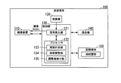
- FIG. 1 shows the configuration of the communication system 10 according to the first embodiment of the present invention.
- the communication system 10 shown in FIG. 1 has a transmitting terminal 100 and a receiving terminal 200.
- the transmitting terminal 100 and the receiving terminal 200 carry out communication for transmitting an image (video).
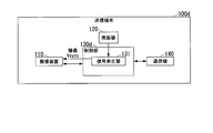
- FIG. 2 shows the configuration of the transmitting terminal 100.
- the transmission terminal 100 shown in FIG. 2 includes an image pickup device 110, an oscillator 120, a control unit 130, a communication device 140 (first communication device), and a recording medium 150.
- the control unit 130 includes a signal generator 131 (first signal generator) and a processor 132.
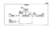
- FIG. 3 shows the configuration of the receiving terminal 200.
- the receiving terminal 200 shown in FIG. 3 has a communication device 210 (second communication device), an oscillator 220, a control unit 230, and a display device 240.
- the control unit 230 has a signal generator 231 (second signal generator).
- the signal generator 131 generates a first synchronization signal that defines the imaging cycle.
- the image pickup apparatus 110 takes an image of the subject according to the first synchronization signal.
- the communication device 140 transmits the image generated by the image pickup device 110.
- the communication device 210 receives the image transmitted by the communication device 140.
- the signal generator 231 generates a second synchronization signal that defines the display period.
- the image received by the communication device 210 is output to the display device 240.
- the display device 240 displays an image according to the second synchronization signal.
- the processor 132 calculates an adjustment value indicating the difference between the imaging cycle and the display cycle.
- the processor 132 adjusts the signal generator 131 based on the adjustment value to match the imaging cycle and the display cycle.
- the connection history in which the adjustment information and the identification information are associated with each other is recorded on the recording medium 150.
- the adjustment information directly or indirectly indicates the adjustment value.
- the identification information identifies one of the communication device 140 and the communication device 210. When the communication device 140 and the communication device 210 are reconnected to each other, if the identification information corresponding to one of the communication device 140 and the communication device 210 is recorded in the recording medium 150, the processor 132 and the identification information in the connection history.
- the signal generator 131 is adjusted based on the adjustment value indicated by the associated adjustment information.
- the processor 132 acquires identification information for identifying the communication device 210.
- the communication device 210 transmits the identification information to the communication device 140.
- the processor 132 receives the identification information from the communication device 210 by using the communication device 140.
- the processor 132 calculates the adjustment value
- the processor 132 records the connection history in which the adjustment information and the identification information are associated with each other on the recording medium 150.
- the processor 132 determines whether or not the newly acquired identification information is the same as the identification information recorded on the recording medium 150.
- the processor 132 determines that the newly acquired identification information is the same as the identification information recorded on the recording medium 150, the processor 132 is based on the adjustment value indicated by the adjustment information associated with the identification information in the connection history. Adjust the signal generator 131.
- the image pickup device 110 is an image sensor such as a CMOS (Complementary Metal Oxide Sensor) sensor.
- the image pickup apparatus 110 generates an image at the timing indicated by the vertical synchronization signal (imaging Vsync) generated by the signal generator 131.
- the imaging Vsync includes repetitive pulses.
- the period of the imaging Vsync is the time interval at which the pulse is generated.
- the period of the imaging Vsync indicates the imaging cycle.
- the speed (frame rate) at which the image pickup apparatus 110 is driven is not limited to 60 fps.
- One image (1 frame) is generated for each imaging cycle.
- the image pickup apparatus 110 generates an image by continuously generating a plurality of images.
- the image pickup apparatus 110 outputs an image to the control unit 130.
- the oscillator 120 is a crystal oscillator.
- the oscillator 120 generates a source clock and outputs the source clock to the signal generator 131.
- the signal generator 131 is a sink generator.
- the signal generator 131 generates a first synchronization signal based on the source vibration clock output from the oscillator 120.
- the first synchronization signal includes a vertical synchronization signal (imaging Vsync) and a horizontal synchronization signal.
- the horizontal sync signal includes repetitive pulses.
- the period of the horizontal synchronization signal is the time interval at which the pulse is generated.
- the period of the horizontal synchronization signal indicates the timing of scanning each row in the pixel array of the image pickup apparatus 110. In the following, an example in which the period of the imaging Vsync is used to adjust the period of the synchronization signal will be described.
- the signal generator 131 outputs the first synchronization signal to the image pickup apparatus 110.
- the signal generator 131 has a cycle counter that defines the cycle of the imaging Vsync. By adjusting the value measured by the cycle counter of the signal generator 131, the cycle of the imaging Vsync is adjusted.
- the processor 132 is at least one of a CPU (Central Processing Unit), a DSP (Digital Signal Processor), and a GPU (Graphics Processing Unit).
- the processor 132 may be configured by a logic circuit such as an ASIC (Application Specific Integrated Circuit) or an FPGA (Field-Programmable Gate Array).
- the transmitting terminal 100 may have a plurality of processors.
- the processor 132 outputs the image output from the image pickup device 110 to the communication device 140.
- the processor 132 has functions as a cycle measurement unit 133, a cycle adjustment unit 134, and an adjustment value detection unit 135.
- the cycle measurement unit 133 measures the difference between the imaging cycle and the display cycle, and calculates an adjustment value indicating the difference.
- the cycle adjustment unit 134 adjusts the signal generator 131 based on the adjustment value.
- the signal generator 131 is adjusted so that the cycle (imaging cycle) of the imaging Vsync generated by the signal generator 131 matches the display cycle.
- the adjustment value detection unit 135 determines whether or not the identification information received from the communication device 210 is included in the connection history recorded on the recording medium 150. To do. When the identification information received from the communication device 210 is included in the connection history, the adjustment value detection unit 135 detects an adjustment value that can be used for adjusting the imaging cycle. When the adjustment value detection unit 135 determines that the identification information received from the communication device 210 is included in the connection history, the cycle adjustment unit 134 signals based on the adjustment value associated with the identification information in the connection history. Adjust the generator 131.
- the oscillation cycle of the source clock generated by the oscillator 120 has a period deviation peculiar to the oscillator 120. This deviation is the difference between the ideal design period and the actual period. Similarly, the oscillation period of the source clock generated by the oscillator 220 has a period deviation inherent in the oscillator 220. If the environment in which the transmitting terminal 100 and the receiving terminal 200 are arranged does not change, it is assumed that the deviation of the oscillation cycle of the source clock does not change. Therefore, when the communication device 140 and the communication device 210 are reconnected to each other, the adjustment value used in the past connection can be used for the adjustment of the imaging cycle.
- the processor 132 may read the program and execute the read program.
- the program contains instructions that specify the operation of processor 132. That is, the function of the processor 132 may be realized by software.
- the program may be provided by a "computer-readable recording medium” such as flash memory.
- the program may be transmitted from the computer holding the program to the transmission terminal 100 via the transmission medium or by the transmission wave in the transmission medium.
- a "transmission medium” for transmitting a program is a medium having a function of transmitting information.
- the medium having a function of transmitting information includes a network (communication network) such as the Internet and a communication line (communication line) such as a telephone line.
- the above-mentioned program may realize a part of the above-mentioned function.
- the above-mentioned program may be a difference file (difference program). The combination of the program already recorded in the computer and the difference program may realize the above-mentioned function.
- the communication device 140 communicates with the communication device 210.
- the communication device 140 is a wireless module having an antenna and a wireless circuit.
- the communication device 140 carries out wireless communication by radiating a radio wave to the communication device 210 or receiving a radio wave radiated from the communication device 210.
- the communication device 140 may be connected to a cable and carry out wired communication.
- the processor 132 transmits an image or information to the receiving terminal 200 by using the communication device 140. Specifically, the processor 132 controls the communication device 140 so that the image or information is transmitted to the receiving terminal 200. That is, the processor 132 causes the communication device 140 to transmit an image or information for the receiving terminal 200. As a result, the communication device 140 transmits the image or information to the receiving terminal 200.
- the processor 132 receives information from the receiving terminal 200 by using the communication device 140. Specifically, the processor 132 controls the communication device 140 so that the information is received from the receiving terminal 200. That is, the processor 132 causes the communication device 140 to receive the information from the receiving terminal 200. As a result, the communication device 140 receives the information from the receiving terminal 200.
- the recording medium 150 is a volatile or non-volatile recording medium.
- the recording medium 150 RAM (Random Access Memory), DRAM (DynamicRandom Access Memory), SRAM (Static Random Access Memory), EEPROM (Electrically Erasable Programmable Read-Only Memory), FRAM (registered trademark) (Ferroelectric Random Access Memory ), Flash memory, and at least one of the hard disk drives.
- the recording medium 150 stores the connection history.
- the adjustment value calculated by the periodic measurement unit 133 and the identification information for identifying the communication device 210 are associated with each other.
- the connection history may include a plurality of combinations of adjustment values and identification information.
- the image pickup device 110 is included in the transmission terminal 100.
- the imaging device 110 is not essential to the transmitting terminal 100.
- the image pickup apparatus 110 may be arranged outside the transmission terminal 100 and may be connected to the transmission terminal 100 by wire or wirelessly.
- the recording medium 150 is included in the transmission terminal 100.
- the recording medium 150 is not essential to the transmitting terminal 100.
- the recording medium 150 may be arranged outside the transmission terminal 100 and may be connected to the transmission terminal 100 by wire or wirelessly.
- the communication device 210 communicates with the communication device 140.
- the communication device 210 is a wireless module having an antenna and a wireless circuit.
- the communication device 210 carries out wireless communication by radiating a radio wave to the communication device 140 or receiving a radio wave radiated from the communication device 140.
- the communication device 210 may be connected to a cable and carry out wired communication.
- the communication device 210 receives the image or information transmitted from the transmission terminal 100. Further, the communication device 210 transmits the information to the transmission terminal 100.
- the oscillator 220 is a crystal oscillator.
- the oscillator 220 generates a source clock and outputs the source clock to the signal generator 231.
- the control unit 230 outputs the image output from the communication device 210 to the display device 240.
- the signal generator 231 is a sink generator.
- the signal generator 231 generates a second synchronization signal based on the source vibration clock output from the oscillator 220.
- the second sync signal includes a vertical sync signal (display Vsync) and a horizontal sync signal.
- the period of the horizontal synchronization signal indicates the timing of scanning each line on the screen of the display device 240. In the following, an example in which the period of the display Vsync is used to adjust the period of the synchronization signal will be described.
- the signal generator 231 outputs the second synchronization signal to the display device 240.
- the control unit 230 may have a processor.
- the display device 240 is a monitor.
- the display device 240 is a liquid crystal display or an organic EL (Electroluminescence) display.
- the display device 240 displays an image at the timing indicated by the vertical synchronization signal (display Vsync) generated by the signal generator 231.
- the display Vsync includes repetitive pulses.
- the period of the display Vsync is the time interval at which the pulse is generated.
- the cycle of the display Vsync indicates the display cycle.
- the display cycle is 16.6 ms.
- the speed (frame rate) at which the display device 240 updates the image is not limited to 60 fps.
- One image (1 frame) is displayed for each display cycle.
- the display device 240 displays an image by continuously displaying a plurality of images.
- the display device 240 is included in the receiving terminal 200.
- the display device 240 is not essential to the receiving terminal 200.
- the display device 240 may be arranged outside the receiving terminal 200 and may be connected to the receiving terminal 200 by wire or wirelessly.
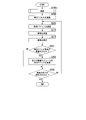
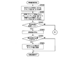
- FIG. 4 shows a procedure for operating the transmitting terminal 100.
- the processor 132 executes the connection process (step S100).
- the processor 132 connects to the communication device 210 of the receiving terminal 200 by using the communication device 140 in the connection process.
- the connection process is executed, a communication link between the transmitting terminal 100 and the receiving terminal 200 is established, and data communication becomes possible. Details of step S100 will be described later.
- the communication device 140 acquires the identification information of the communication device 210 by receiving the identification information of the communication device 210 from the communication device 210.
- the processor 132 determines whether or not the identification information received from the communication device 210 is included in the connection history recorded on the recording medium 150. As a result, the processor 132 determines whether or not the adjustment value is included in the connection history (step S105).
- the adjustment value and the identification information of the communication device 210 are not included in the connection history. If the identification information is not included in the connection history, the processor 132 determines that the adjustment value is not included in the connection history. When the communication device 140 and the communication device 210 have been connected to each other in the past, and the communication device 140 and the communication device 210 are connected to each other again, the adjustment value and the identification information of the communication device 210 are included in the connection history. When the identification information is included in the connection history, the processor 132 determines that the adjustment value is included in the connection history.
- the processor 132 determines in step S105 that the adjustment value is included in the connection history
- the processor 132 reads the adjustment value associated with the identification information received from the communication device 210 in the connection history from the recording medium 150. ..
- the processor 132 adjusts the period of the imaging Vsync by applying the adjusted value to the signal generator 131 (step S110). As a result, the period of the imaging Vsync and the period of the display Vsync match.
- the method of adjusting the cycle of the imaging Vsync in step S110 is the same as the method of adjusting the cycle of the imaging Vsync in step S1625 (FIG. 9) described later.
- the communication device 210 transmits a synchronization packet to the communication device 140 at each display Vsync cycle. For example, when the display cycle is 16.6 ms, the communication device 210 periodically transmits a synchronization packet to the communication device 140 at an interval of 16.6 ms.
- the synchronization packet contains information used to adjust the phase and period of the imaging Vsync. Since the synchronization adjustment process is executed at the transmission terminal 100, the synchronization packet is transmitted before a predetermined time of the timing at which the display Vsync pulse is output.
- step S120 the processor 132 performs phase adjustment (step S120).
- the processor 132 matches the phase of the imaging Vsync with the phase of the display Vsync by matching the timing of the imaging Vsync with the timing of the display Vsync. Details of step S120 will be described later.
- the processor 132 causes the imaging device 110 to perform imaging.
- the image pickup apparatus 110 performs imaging and generates an image (step S125).
- the processor 132 transmits an image to the communicator 210 by using the communicator 140 (step S130).
- An image that has undergone image processing such as compression may be transmitted.
- the processor 132 determines whether or not the end of imaging is instructed (step S135).
- the transmitting terminal 100 has an operation unit operated by the user.
- the processor 132 determines whether or not the end of imaging is instructed based on the operation result of the operation unit. For example, when the power of the transmission terminal 100 is instructed to be turned off, the processor 132 determines that the end of imaging is instructed. If the power of the transmitting terminal 100 is not instructed to be turned off, the processor 132 determines that the end of imaging is not instructed.
- step S135 When the processor 132 determines in step S135 that the end of imaging is instructed, the process shown in FIG. 4 ends. In this case, the processor 132 disconnects the connection between the communication device 140 and the communication device 210. If the processor 132 determines in step S135 that the end of imaging is not instructed, step S115 is executed.
- step S105 the communication device 140 waits for the reception of the synchronization packet.
- the communication device 140 receives the synchronization packet.
- the processor 132 acquires a synchronization packet from the communication device 140 (step S140).
- Step S145 is the same as step S120.
- the processor 132 causes the imaging device 110 to perform imaging.
- the image pickup apparatus 110 performs an image pickup according to the image pickup Vsync and generates an image (step S150).
- the processor 132 transmits an image to the communicator 210 by using the communicator 140 (step S155).
- step S155 the processor 132 performs periodic adjustment (step S160).
- step S160 the processor 132 matches the period of the imaging Vsync with the period of the display Vsync. Details of step S160 will be described later.
- step S160 the processor 132 associates the adjustment value calculated in step S160 with the identification information of the communication device 210.
- the processor 132 records the connection history including the adjustment value and the identification information on the recording medium 150 (step S165). After step S165, step S135 is executed.
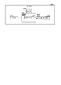
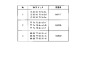
- FIG. 5 shows an example of the connection history recorded on the recording medium 150.
- the identification information and adjustment values in the same line are related to each other. For example, the identification information A0000xxxxxx and the adjustment value 0x01ff are associated with each other.
- the cycle adjustment is performed in step S160, and the adjustment value is recorded on the recording medium 150 in step S165.
- step S110 the adjustment value associated with the identification information is read from the recording medium 150, and the adjustment value is used to adjust the period of the imaging Vsync.
- the control unit 230 executes the connection process (step S200).
- the control unit 230 connects to the communication device 140 of the transmission terminal 100 by using the communication device 210 in the connection process. Details of step S200 will be described later.
- the communication device 210 transmits a synchronization packet to the communication device 140 (step S205).
- the communication device 210 receives an image from the communication device 140 (step S210).
- the received image is output to the display device 240 via the control unit 230.
- the display device 240 displays an image according to the display Vsync (step S215).
- step S215 the control unit 230 determines whether or not the end of the display has been instructed (step S220). For example, in step S130 shown in FIG. 4, when the processor 132 determines that the end of imaging is instructed, the processor 132 transmits the end instruction to the communication device 210 by using the communication device 140. When the end instruction is transmitted from the communication device 140, the communication device 210 receives the end instruction. When the communication device 210 receives the end instruction, the control unit 230 determines that the end of the display has been instructed. If the communication device 210 has not received the end instruction, the control unit 230 determines that the end of the display has not been instructed.
- the receiving terminal 200 may have an operation unit operated by the user.
- the control unit 230 may determine whether or not the end of the display is instructed based on the operation result of the operation unit. For example, when the power of the receiving terminal 200 is instructed to be turned off, the control unit 230 may determine that the end of the display is instructed. When the power off of the receiving terminal 200 is not instructed, the control unit 230 may determine that the end of the display is not instructed.
- step S220 When the control unit 230 determines that the end of the display is instructed in step S220, the process shown in FIG. 6 ends. In this case, the control unit 230 disconnects the connection between the communication device 210 and the communication device 140. If the control unit 230 determines in step S220 that the end of the display has not been instructed, step S205 is executed.
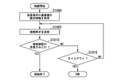
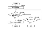
- FIG. 7 shows a procedure for operating the transmitting terminal 100 in the connection process.
- the communication device 140 stands by for receiving the identification information that identifies the communication device 210 of the receiving terminal 200.
- the identification information is transmitted from the communication device 210
- the communication device 140 receives the identification information.
- the processor 132 acquires the identification information from the communication device 140 (step S1000).
- step S1000 the processor 132 transmits a connection request to the communication device 210 by using the communication device 140 (step S1005).
- the communication device 210 receives the connection request and transmits the connection confirmation to the communication device 140.
- the communication device 140 receives the connection confirmation.
- the processor 132 determines whether or not the connection confirmation has been received (step S1010). For example, in step S1010, the processor 132 determines whether or not the connection confirmation has been received within a predetermined time from the timing when the connection request is transmitted.
- step S1010 When the processor 132 determines that the connection confirmation has been received in step S1010, the process shown in FIG. 7 ends, and step S105 shown in FIG. 4 is executed. In this case, the connection between the communication device 140 and the communication device 210 is established.
- the communication device 140 and the communication device 210 can carry out image communication.
- step S1015 the processor 132 determines whether or not a timeout has occurred. For example, the processor 132 determines whether or not the time elapsed from the timing when the connection request is first transmitted exceeds the predetermined time. If the time exceeds a predetermined time, the processor 132 determines that a timeout has occurred. If the time does not exceed the predetermined time, the processor 132 determines that the timeout has not occurred.
- step S1015 When the processor 132 determines that a timeout has occurred in step S1015, the processes shown in FIGS. 7 and 4 end. If the processor 132 determines in step S1015 that no timeout has occurred, step S1005 is executed.
- the communication device 140 receives the identification information from the communication device 210.
- the communication method of the identification information is not limited to this.
- the transmitting terminal 100 may have two or more communicators including the communicator 140, and the receiving terminal 200 may have two or more communicators including the communicator 210.
- the communication device of the transmission terminal 100 other than the communication device 140 may receive the identification information of the communication device 210 from the communication device of the reception terminal 200 other than the communication device 210. That is, the transmitting terminal 100 may receive the identification information from the receiving terminal 200 by using a communication device other than the communication device 140 used for transmitting the image.
- FIG. 8 shows a procedure for operating the transmitting terminal 100 in phase adjustment.
- the synchronization packet received in step S115 or step S140 includes a value indicating the timing of the next pulse of the display Vsync.
- the processor 132 extracts the value from the synchronous packet (step S1200).
- step S1200 the processor 132 calculates the timing of the next pulse of the imaging Vsync based on the value extracted from the synchronization packet.
- the processor 132 sets the calculated timing in the signal generator 131 (step S1205).
- step S1205 is executed, the process shown in FIG. 8 ends, and step S125 or step S150 shown in FIG. 4 is executed.
- the synchronization packet contains information indicating the time of the next pulse of the display Vsync.
- the processor 132 subtracts the time when the synchronization packet is received from the time of the next pulse of the display Vsync. As a result, the processor 132 calculates the time required until the timing of the next pulse of the imaging Vsync. The processor 132 adjusts the signal generator 131 to generate a pulse of the imaging Vsync when the calculated time has elapsed.
- step S115 or step S140 If the synchronization packet is not received in step S115 or step S140, the imaging is performed without performing the phase adjustment, and the image is transmitted.
- FIG. 9 shows a procedure of operation of the transmission terminal 100 in the cycle adjustment.
- a method similar to the method described in WO 2018/235258 can be applied to the periodic adjustment in the embodiments of the present invention.
- the processor 132 acquires the counter value CNT_A in the cycle of the imaging Vsync from the signal generator 131 (step S1600).
- the signal generator 131 has a counter for measuring time.
- the value of the counter increases from the initial value at the reference timing.
- the processor 132 acquires the counter value CNT_A at the timing when a pulse synchronized with the period of the imaging Vsync is generated.
- the counter value CNT_A corresponds to the length of a predetermined number of cycles of the imaging Vsync.
- the processor 132 extracts the frame counter value from the synchronization packet received in step S140.
- the frame counter value indicates the number of frame periods included in the period starting from the reference timing. For example, when the imaging cycle and the display cycle are 16.6 ms, the length of one frame period is 16.6 ms.
- the frame counter value corresponds to the frame number.
- the processor 132 calculates the counter value CNT_B in the period of the display Vsync based on the frame counter value (step S1605).
- the signal generator 231 of the receiving terminal 200 has a counter for measuring time.
- the value of the counter (counter value CNT_B) increases from the initial value at the reference timing.
- the counter value CNT_B increases by a fixed value in one frame period. For example, its fixed value is 1,000,000.
- the fixed value is not limited to 1,000,000.
- the processor 132 calculates the counter value CNT_B by multiplying the fixed value by the frame counter value.
- the fixed value may be recorded on the recording medium 150.
- the processor 132 may receive a fixed value from the communication device 210 by using the communication device 140.
- the fixed value may be stored in the synchronization packet.
- the processor 132 determines whether or not a predetermined time has elapsed (step S1610).
- the predetermined time is 60 seconds.
- the predetermined time may be a time other than 60 seconds.
- the processor 132 determines the time elapsed from the timing when the communication device 140 and the communication device 210 are connected to each other. If the time is shorter than the predetermined time, the processor 132 determines that the predetermined time has not elapsed. If the time is equal to or longer than the predetermined time, the processor 132 determines that the predetermined time has elapsed.
- step S140 is executed.
- the synchronization packet is repeatedly received and the counter value CNT_A and the counter value CNT_B are repeatedly acquired until the predetermined time elapses.
- the processor 132 measures the difference between the period of the imaging Vsync and the period of the display Vsync, and calculates an adjustment value indicating the difference (step S1615). ).
- a plurality of counter values CNT_A and a plurality of counter values CNT_B are acquired at a predetermined time.
- the processor 132 selects the counter value CNT_A and the counter value CNT_B at each of the two times included in the predetermined time.
- the processor 132 selects the counter value CNT_A (t0) and the counter value CNT_B (t0) at the time t0, and the counter value CNT_A (t1) and the counter value CNT_B (t1) at the time t1.
- Select t1 selects the counter value CNT_A (t0) and the counter value CNT_B (t0) at the time t0, and the counter value CNT_A (t1) and the counter value CNT_B (t1) at the time t1.
- the processor 132 calculates the period Ti of the imaging Vsync according to the following equation (1), and calculates the period Td of the display Vsync according to the following equation (2).
- Ti ⁇ CNT_A (t1) -CNT_A (t0) ⁇ / (t1-t0) ...
- Td ⁇ CNT_B (t1) -CNT_B (t0) ⁇ / (t1-t0) ...
- step S1620 the processor 132 determines whether or not periodic adjustment is necessary.
- step S1620 the processor 132 calculates the difference between the maximum value of the cycle counter of the signal generator 131 and the maximum value of the cycle counter of the signal generator 231. The maximum value of each cycle counter will be described later.
- step S1620 the processor 132 determines whether or not the adjustment value is smaller than the difference. If the adjustment value is smaller than the difference, the processor 132 determines that periodic adjustment is necessary. If the adjustment value is larger than the difference, the processor 132 determines that the periodic adjustment is not necessary. For example, when the difference is a value corresponding to 50 ppm and the adjusted value is a value corresponding to 10 ppm, the processor 132 determines that periodic adjustment is necessary.
- the signal generator 131 has a cycle counter that measures the cycle of the imaging Vsync.
- the value of the cycle counter increases from the initial value at the timing when the cycle of the imaging Vsync starts.
- the value of the cycle counter reaches the preset maximum value, the value of the cycle counter is reset to the initial value.
- the signal generator 131 generates a pulse of the imaging Vsync based on the value of the cycle counter. For example, the signal generator 131 generates a pulse of the imaging Vsync at the timing when the value of the cycle counter is reset.
- the signal generator 231 has a cycle counter that measures the cycle of the display Vsync.
- the value of the cycle counter is increased from the initial value at the timing when the cycle of the display Vsync is started.
- the value of the cycle counter reaches the preset maximum value, the value of the cycle counter is reset to the initial value.
- the signal generator 231 generates a pulse of display Vsync based on the value of its cycle counter. For example, the signal generator 231 generates a pulse of display Vsync at the timing when the value of the cycle counter is reset.
- the maximum value of each cycle counter of the signal generator 131 and the signal generator 231 may be recorded on the recording medium 150.
- the processor 132 may receive the maximum value of the cycle counter of the signal generator 231 from the communication device 210 by using the communication device 140.
- the maximum value of the period counter of the signal generator 231 may be stored in the synchronization packet.
- step S1620 When the processor 132 determines in step S1620 that the cycle adjustment is necessary, the processor 132 updates the value of the cycle counter of the signal generator 131 based on the calculated adjustment value (step S1625). By executing step S1625, the processor 132 matches the period of the imaging Vsync with the period of the display Vsync.
- the processor 132 calculates a new maximum value by subtracting the adjustment value from the maximum value of the cycle counter of the signal generator 131 in step S1625 in order to shorten the period of the imaging Vsync. In step S1625, the processor 132 updates the maximum value of the period counter of the signal generator 131 to a new maximum value.
- the processor 132 calculates a new maximum value by adding an adjustment value to the maximum value of the cycle counter of the signal generator 131 in step S1625 in order to lengthen the period of the imaging Vsync. In step S1625, the processor 132 updates the maximum value of the period counter of the signal generator 131 to a new maximum value.
- step S1625 When step S1625 is executed, the process shown in FIG. 9 is completed, and step S165 shown in FIG. 4 is executed.
- the processor 132 determines in step S1620 that the cycle adjustment is not necessary, the process shown in FIG. 9 ends, and step S165 shown in FIG. 4 is executed.
- step S1625 The adjustment value calculated in step S1625 is recorded on the recording medium 150 in step S165 shown in FIG. If the processor 132 determines in step S1620 that the cycle adjustment is not necessary, information indicating that the cycle adjustment is not necessary may be recorded in the recording medium 150 in step S165 shown in FIG. The information is associated with the identification information of the communication device 210.
- step S105 shown in FIG. 4 when the processor 132 determines that the identification information received from the communication device 210 is included in the connection history, the processor 132 may execute the following processing. If the adjustment value is associated with the identification information in the connection history, the processor 132 executes step S110 described above. When the information indicating that the cycle adjustment is not necessary is associated with the identification information in the connection history, the processor 132 may execute step S115 without executing step S110.
- the adjustment value for adjusting the cycle of the imaging Vsync is the difference between the cycle of the imaging Vsync and the cycle of the display Vsync. If the specifications of the source vibration clock generated by the oscillator 120 of the transmitting terminal 100 and the specifications of the source vibration clock generated by the oscillator 220 of the receiving terminal 200 are the same, even if the difference in the period deviation is used as the adjustment value. Good. Specifically, the difference (first value) between the ideal design period of the imaging Vsync and the actual period of the imaging Vsync is calculated. The first value indicates the deviation of the period of the imaging Vsync.
- the difference (second value) between the ideal display Vsync period in design and the actual display Vsync period is calculated.
- the second value indicates the deviation of the period of the display Vsync.
- the difference between the first value and the second value is the difference in the deviation of the period.
- the adjustment information is information that directly indicates the adjustment value.
- the adjustment information may be information that indirectly indicates the adjustment value.
- Information necessary for calculating the adjustment value may be recorded on the recording medium 150 as adjustment information indirectly indicating the adjustment value.
- the imaging cycle and the display cycle used for calculating the adjustment value are recorded on the recording medium 150 as adjustment information. That is, the period Ti of the imaging Vsync shown in the formula (1) and the period Td of the display Vsync shown in the formula (2) are recorded on the recording medium 150.
- the processor 132 calculates the adjustment value Va according to the equation (3) and applies the adjustment value Va to the signal generator 131.
- the information required to calculate the adjustment value is not limited to the imaging cycle and display cycle.
- the counter value CNT_A and the counter value CNT_B shown in the equations (1) and (2) may be recorded on the recording medium 150 as adjustment information.
- the processor 132 may calculate the period Ti of the imaging Vsync and the period Td of the display Vsync according to the equations (1) and (2). Further, the processor 132 may calculate the adjustment value Va according to the equation (3) in step S110 and apply the adjustment value Va to the signal generator 131.
- FIG. 10 shows a procedure of operation of the receiving terminal 200 in the connection process.
- control unit 230 transmits the identification information that identifies the communication device 210 to the communication device 140 of the transmission terminal 100 (step S2000).
- step S2000 the communication device 210 waits for receiving the connection request.
- the connection request is transmitted from the communication device 140
- the communication device 210 receives the connection request.
- the control unit 230 determines whether or not the connection request has been received (step S2005). For example, in step S2005, the control unit 230 determines whether or not the connection request has been received within a predetermined time from the timing at which the identification information is transmitted.
- step S2010 the control unit 230 transmits the connection confirmation to the communication device 140 by using the communication device 210 (step S2010).
- step S2010 the process shown in FIG. 10 is completed, and step S205 shown in FIG. 6 is executed.
- the connection between the communication device 140 and the communication device 210 is established.
- the communication device 140 and the communication device 210 can carry out image communication.
- step S2015 determines whether or not a timeout has occurred. For example, the control unit 230 determines whether or not the time elapsed from the timing at which the identification information is transmitted in step S2000 exceeds a predetermined time. If the time exceeds a predetermined time, the control unit 230 determines that a time-out has occurred. If the time does not exceed the predetermined time, the control unit 230 determines that a timeout has not occurred.
- step S2015 determines that a timeout has occurred in step S2015.
- the processes shown in FIGS. 10 and 6 end. If the control unit 230 determines in step S2015 that no timeout has occurred, step S2005 is executed.
- the communication device 210 transmits the identification information of the communication device 210 to the communication device 140.
- the communication devices of the receiving terminal 200 other than the communication device 210 communicate the identification information of the communication device 210. It may be transmitted to the communication device of the transmission terminal 100 other than the machine 140. That is, the receiving terminal 200 may transmit the identification information to the transmitting terminal 100 by using a communication device other than the communication device 210 used for receiving the image.
- the period of the vertical synchronization signal (imaging Vsync) is adjusted.
- the period of the horizontal synchronization signal may be adjusted by using the same method as the above method.
- the communication method of each aspect of the present invention has a calculation step, a first adjustment step, and a second adjustment step.
- the processor 132 calculates an adjustment value indicating the difference between the imaging cycle and the display cycle in the calculation step (step S1615).
- the processor 132 adjusts the signal generator 131 based on the adjustment value in the first adjustment step (step S1625) to match the imaging cycle and the display cycle.
- the connection history in which the adjustment information and the identification information are associated with each other is recorded on the recording medium 150.
- the adjustment information directly or indirectly indicates the adjustment value.
- the identification information identifies one of the communication device 140 and the communication device 210.
- the processor 132 When the communication device 140 and the communication device 210 are reconnected to each other, the processor 132 has a second adjustment step (step) if the identification information corresponding to one of the communication device 140 and the communication device 210 is recorded on the recording medium 150.
- the signal generator 131 is adjusted based on the adjustment value indicated by the adjustment information associated with the identification information in the connection history.
- the communication method of each aspect of the present invention does not need to have steps other than the calculation step, the first adjustment step, and the second adjustment step.
- the processor 132 determines whether or not the identification information of the communication device 210 is recorded on the recording medium 150.
- the processor 132 adjusts the signal generator 131 based on the adjustment value indicated by the adjustment information associated with the identification information in the connection history. In this case, the processor 132 does not need to execute step S160 shown in FIG. Therefore, the communication system 10 can match the cycles of the synchronization signals of the transmitting terminal 100 and the receiving terminal 200 in a short time.
- step S110 When step S110 is executed, the cycle of the imaging Vsync and the cycle of the display Vsync match in a short time. After the step S120 shown in FIG. 4 is executed, the state in which the imaging Vsync and the display Vsync are synchronized with each other is likely to be maintained. Therefore, the communication system 10 can avoid the loss of video data.
- FIG. 2 (Modified example of the first embodiment) A first modification of the first embodiment of the present invention will be described.
- the transmission terminal 100 shown in FIG. 2 is changed to the transmission terminal 100a shown in FIG.
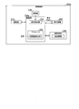
- FIG. 11 shows the configuration of the transmission terminal 100a. The description of the same configuration as that shown in FIG. 2 will be omitted.
- the control unit 130 shown in FIG. 2 is changed to the control unit 130a.
- the processor 132 shown in FIG. 2 is changed to the processor 132a.
- the processor 132a has functions as a cycle measuring unit 133 and a cycle adjusting unit 134.
- the processor 132a does not have a function as the adjustment value detection unit 135 shown in FIG.
- the transmission terminal 100a does not have the recording medium 150 shown in FIG.
- the communication device 140 transmits identification information for identifying the communication device 140 to the communication device 210.
- the identification information is the MAC address of the communication device 140.
- the information that identifies the transmitting terminal 100a may be used as the identification information of the communication device 140.
- the identification information may be a serial number that can uniquely identify the transmitting terminal 100a.
- the receiving terminal 200 shown in FIG. 3 is changed to the receiving terminal 200a shown in FIG.
- FIG. 12 shows the configuration of the receiving terminal 200a. The description of the same configuration as that shown in FIG. 3 will be omitted.
- the receiving terminal 200a has a recording medium 250.
- the recording medium 250 is a volatile or non-volatile recording medium.
- the recording medium 250 is at least one of RAM, DRAM, SRAM, EEPROM, FRAM®, flash memory, and a hard disk drive.
- the recording medium 250 stores the connection history.
- the adjustment value calculated by the periodic measurement unit 133 and the identification information for identifying the communication device 140 are associated with each other.
- control unit 230 shown in FIG. 3 is changed to the control unit 230a.
- the control unit 230a has a signal generator 231 and a processor 232.
- the processor 232 has a function as an adjustment value detection unit 235.
- the adjustment value detection unit 235 determines whether or not the identification information received from the communication device 140 is included in the connection history recorded on the recording medium 250. To do.
- the adjustment value detection unit 235 detects an adjustment value that can be used for adjusting the imaging cycle.
- the processor 232 may read the program and execute the read program.
- the program contains instructions that specify the operation of processor 232. That is, the function of the processor 232 may be realized by software.
- the program is realized in the same manner as the program that realizes the function of the processor 132.
- the processor 232 transmits information to the transmission terminal 100a by using the communication device 210. Specifically, the processor 232 controls the communication device 210 so that the information is transmitted to the transmission terminal 100a. That is, the processor 232 causes the communication device 210 to transmit the information for the transmission terminal 100a. As a result, the communication device 210 transmits the information to the transmission terminal 100a.
- the processor 232 receives an image or information from the transmitting terminal 100a by using the communication device 210. Specifically, the processor 232 controls the communication device 210 so that the image or information is received from the transmission terminal 100a. That is, the processor 232 causes the communication device 140 to receive the image or information from the transmission terminal 100a. As a result, the communication device 210 receives the image or information from the transmission terminal 100a.
- the processor 232 acquires identification information for identifying the communication device 140.
- the communication device 140 transmits the identification information to the communication device 210.
- the processor 232 receives the identification information from the communication device 140 by using the communication device 210.
- the processor 132 uses the communication device 140 to transmit the adjustment information indicating the adjustment value to the communication device 210.
- the processor 232 receives the adjustment information from the communication device 140 by using the communication device 210.
- the processor 232 records the connection history in which the adjustment information and the identification information are associated with each other on the recording medium 250.
- the processor 232 determines whether or not the newly acquired identification information is the same as the identification information recorded on the recording medium 250. When the processor 232 determines that the newly acquired identification information is the same as the identification information recorded on the recording medium 250, the processor 232 transfers the adjustment information associated with the identification information in the connection history to the communication device 210. By using it, it is transmitted to the communication device 140.
- the processor 132 receives the adjustment information from the communication device 210 by using the communication device 140.
- the processor 132 adjusts the signal generator 131 based on the adjustment information received from the communication device 210.
- FIG. 13 shows a procedure for operating the transmitting terminal 100a. The description of the same process as that shown in FIG. 4 will be omitted.
- the processor 132a executes the connection process (step S100a).
- the connection process is the same as the connection process shown in FIG. 7, except for step S1000 shown in FIG. 7.
- the processor 132a transmits the identification information of the communication device 140 to the communication device 210 of the receiving terminal 200a by using the communication device 140.
- the communication device 210 of the receiving terminal 200a transmits the adjusted value to the communication device 140.
- the communication device 140 receives the adjustment value.
- the processor 132a determines whether or not the adjustment value has been received (step S105a). For example, in step S105a, the processor 132a determines whether or not the adjustment value is received within a predetermined time from the timing when the connection process is executed. If the processor 132a determines that the adjustment value has been received in step S105a, step S110 is executed.
- step S110 the processor 132a adjusts the cycle of the imaging Vsync by applying the adjustment value received from the communication device 210 to the signal generator 131. If the processor 132a determines in step S105a that the adjustment value has not been received, step S140 is executed.
- step S160 the processor 132a transmits the adjustment value calculated in step S160 to the communication device 210 by using the communication device 140 (step S165a). After step S165a, step S135 is executed.
- the communication device 140 transmits the identification information to the communication device 210.
- the communication method of the identification information is not limited to this.
- the transmitting terminal 100a may have two or more communicators including the communicator 140, and the receiving terminal 200a may have two or more communicators including the communicator 210.
- the communication device of the transmission terminal 100a other than the communication device 140 may transmit the identification information of the communication device 210 to the communication device of the reception terminal 200a other than the communication device 210. That is, the transmitting terminal 100a may transmit the identification information to the receiving terminal 200a by using a communication device other than the communication device 140 used for transmitting the image.
- the communication device 140 receives the adjustment value from the communication device 210 in step S105a.
- the communication method of the adjusted value is not limited to this.
- the communicator of the transmitting terminal 100a other than the communicator 140 sets the adjustment value in step S105a. It may be received from the communication device of the receiving terminal 200a other than 210. That is, the transmitting terminal 100a may receive the adjustment value from the receiving terminal 200a by using a communication device other than the communication device 140 used for transmitting the image.
- the communication device 140 transmits the adjustment value to the communication device 210 in step S165a.
- the communication method of the adjusted value is not limited to this.
- the communicator of the transmitting terminal 100a other than the communicator 140 sets the adjustment value in step S165a. It may be transmitted to the communication device of the receiving terminal 200a other than 210. That is, the transmitting terminal 100a may transmit the adjusted value to the receiving terminal 200a by using a communication device other than the communication device 140 used for transmitting the image.
- FIG. 14 shows a procedure for operating the receiving terminal 200a. The description of the same process as that shown in FIG. 6 will be omitted.
- Processor 232 executes the connection process (step S200a).
- the connection process is the same as the connection process shown in FIG. 10, except for step S2000 shown in FIG.
- the processor 232 receives the identification information of the communication device 140 of the transmission terminal 100a from the communication device 140 by using the communication device 210.
- the processor 232 determines whether or not the identification information received from the communication device 140 is included in the connection history recorded on the recording medium 250. As a result, the processor 232 determines whether or not the adjustment value is included in the connection history (step S230). When the communication device 140 and the communication device 210 are connected to each other for the first time, the adjustment value and the identification information of the communication device 140 are not included in the connection history. If the identification information is not included in the connection history, the processor 132 determines that the adjustment value is not included in the connection history.
- the adjustment value and the identification information of the communication device 140 are included in the connection history.
- the processor 132 determines that the adjustment value is included in the connection history.
- step S230 When the processor 232 determines in step S230 that the adjustment value is included in the connection history, the processor 232 reads the adjustment value associated with the identification information received from the communication device 140 in the connection history from the recording medium 250. .. The processor 232 transmits the adjustment value to the communication device 140 by using the communication device 210 (step S231). After step S231, step S205 is executed. If the processor 232 determines in step S230 that the adjustment value is not included in the connection history, step S205 is executed.
- step S215 processor 232 determines whether an adjustment value has been received (step S232). If the processor 232 determines in step S232 that the adjustment value has not been received, step S220 is executed.
- step S232 When the processor 232 determines that the adjustment value has been received in step S232, the processor 232 associates the adjustment value received from the communication device 140 with the identification information of the communication device 140.
- the processor 232 records the connection history including the adjustment value and the identification information on the recording medium 250 (step S233). After step S233, step S220 is executed.
- the communication device 210 receives the identification information of the communication device 140 from the communication device 140.
- the communication devices of the receiving terminal 200a other than the communication device 210 communicate the identification information of the communication device 140. It may be received from a communication device of the transmission terminal 100a other than the machine 140. That is, the receiving terminal 200a may receive the identification information from the transmitting terminal 100a by using a communication device other than the communication device 210 used for receiving the image.
- the communication device 210 transmits the adjustment value to the communication device 140 in step S231.
- the communicator of the receiving terminal 200a other than the communicator 210 sets the adjustment value in step S231. It may be transmitted to the communication device of the transmission terminal 100a other than 140. That is, the receiving terminal 200a may transmit the adjusted value to the transmitting terminal 100a by using a communication device other than the communication device 210 used for receiving the image.
- the communication device 210 receives the adjustment value from the communication device 140 in step S232.
- the communicator of the receiving terminal 200a other than the communicator 210 sets the adjustment value in step S232. It may be received from a communication device of a transmitting terminal 100a other than 140. That is, the receiving terminal 200a may receive the adjusted value from the transmitting terminal 100a by using a communication device other than the communication device 210 used for receiving the image.
- the timings of the transmission of the adjustment value in step S165a and the reception of the adjustment value in step S232 are not limited to the timings shown in FIGS. 13 and 14.
- communication of adjustment values may be carried out on a regular basis. Communication of the adjusted value may be performed after a predetermined time has elapsed from the timing at which the period of the imaging Vsync of the transmitting terminal 100a is adjusted. After being instructed to end the imaging, the adjustment value communication may be performed. The communication of the adjusted value may be performed before the connection between the communication device 140 and the communication device 210 is disconnected.
- the processor 232 of the receiving terminal 200a determines whether or not the identification information of the communication device 140 is recorded on the recording medium 250. to decide.
- the processor 232 uses the communication device 210 to transmit the adjustment information associated with the identification information in the connection history to the communication device 140.
- the processor 132a of the transmission terminal 100a adjusts the signal generator 131 based on the adjustment value indicated by the adjustment information received from the communication device 210. In this case, the processor 132a does not need to execute step S160 shown in FIG.
- the communication system 10 can match the cycles of the synchronization signals of the transmitting terminal 100a and the receiving terminal 200a in a short time.
- the source clock of the transmitting terminal 100a and the source clock of the receiving terminal 200a may change due to temperature and aging. Therefore, the periodic adjustment may be performed between the transmission terminal 100a and the reception terminal 200a at predetermined intervals, and the adjustment value may be updated by rewriting the adjustment value recorded on the recording medium 250. Even when the source clock of the transmitting terminal 100a or the receiving terminal 200a changes, the cycle adjustment operation described in the first embodiment becomes possible.
- the transmission terminal 100b has a temperature sensor 160 (first temperature sensor) in addition to the configuration shown in FIG.
- the temperature sensor 160 has a thermistor.
- the temperature sensor 160 is arranged in the vicinity of the oscillator 120.
- the temperature sensor 160 may come into contact with the oscillator 120.
- the temperature sensor 160 measures the temperature of the oscillator 120 and outputs a signal indicating the temperature to the processor 132.
- the receiving terminal 200 shown in FIG. 3 is changed to the receiving terminal 200b shown in FIG.
- FIG. 16 shows the configuration of the receiving terminal 200b. The description of the same configuration as that shown in FIG. 3 will be omitted.
- the receiving terminal 200b has a temperature sensor 260 (second temperature sensor) in addition to the configuration shown in FIG.
- the temperature sensor 260 has a thermistor.
- the temperature sensor 260 is arranged in the vicinity of the oscillator 220.
- the temperature sensor 260 may come into contact with the oscillator 220.
- the temperature sensor 260 measures the temperature of the oscillator 220 and outputs a signal indicating the temperature to the control unit 230.
- the processor 132 of the transmission terminal 100b acquires temperature information indicating the temperature measured by the temperature sensor 260 of the reception terminal 200b.
- the communication device 210 transmits the temperature information to the communication device 140.
- the processor 132 receives the temperature information from the communication device 210 by using the communication device 140.
- the processor 132 calculates the adjustment value
- the processor 132 records the connection history on the recording medium 150. In the connection history, the temperature measured by the temperature sensor 160, the temperature measured by the temperature sensor 260, the adjustment information indicating the adjustment value, and the identification information for identifying the communication device 210 are associated with each other.
- the processor 132 determines whether or not to correct the adjustment value.
- the processor 132 determines that the adjustment value is corrected, the processor 132 sets the adjustment value indicated by the adjustment information associated with the identification information in the connection history as the first synchronization signal (imaging Vsync) and the second synchronization signal (display Vsync). ) Is corrected based on the temperature characteristics of each source clock. The processor 132 adjusts the signal generator 131 based on the corrected adjustment value.
- FIG. 17 is a graph showing the relationship between the temperature and the oscillation period of the source vibration clock.
- the horizontal axis in FIG. 17 indicates the temperature [° C.]
- the vertical axis in FIG. 17 indicates the oscillation period [ppm] of the source clock.
- the graph in FIG. 17 shows the temperature characteristics of the source clock. For example, when the temperature changes from 25 ° C to 50 ° C, a deviation of ⁇ 2.0 ppm occurs with respect to the oscillation period at 25 ° C.
- the temperature characteristics of the oscillation cycle of the source vibration clock may differ between the oscillator 120 and the oscillator 220.
- a table showing the relationship between the temperature of each of the oscillator 120 and the oscillator 220 and the oscillation period of the source vibration clock is recorded on the recording medium 150.
- FIG. 18 shows an example of the connection history recorded on the recording medium 150.
- the identification information, the adjustment value, the temperature of the transmitting terminal 100b, and the temperature of the receiving terminal 200b are associated with each other.
- the temperature of the transmitting terminal 100b is the temperature measured by the temperature sensor 160.
- the temperature of the receiving terminal 200b is the temperature measured by the temperature sensor 260.
- FIG. 19 shows a procedure for operating the transmitting terminal 100b. The description of the same process as that shown in FIG. 4 will be omitted.
- step S105 when the processor 132 determines that the adjustment value is included in the connection history, the processor 132 acquires the temperature from the temperature sensor 160 (step S170). After step S170, step S115 is executed.
- step S115 the processor 132 receives the synchronization packet from the communication device 210 by using the communication device 140.
- the synchronization packet contains temperature information indicating the temperature measured by the temperature sensor 260 of the receiving terminal 200b.
- processor 132 adjusts the temperature based on the temperature measured by each of the temperature sensor 160 and the temperature sensor 260 and the temperature associated with the identification information received from the communicator 210 in the connection history. It is determined whether or not correction is necessary (step S171).
- the processor 132 calculates the difference in the oscillation cycle generated based on the difference between the temperature in the past connection and the temperature in the current connection for each terminal. Specifically, the processor 132 uses the temperature of the transmission terminal 100b in the connection history, the temperature acquired in step S170, and the temperature characteristic of the oscillation cycle of the source vibration clock in the oscillator 120. For example, the temperature characteristic of the oscillation cycle of the source vibration clock in the oscillator 120 is the same as the graph shown in FIG. The processor 132 calculates the difference ⁇ CNT_A_T of the oscillation period of the oscillator clock in the oscillator 120.
- the temperature of the transmitting terminal 100b in the connection history is 25 ° C. and the temperature acquired in step S170 is 30 ° C.
- the oscillation cycle at a temperature of 25 ° C. is 0 ppm
- the oscillation cycle at a temperature of 30 ° C. is ⁇ 1.0 ppm.
- the difference ⁇ CNT_A_T is ⁇ 1.0 ppm.
- the processor 132 executes the same process as the above process by using the information of the receiving terminal 200b. Specifically, the processor 132 uses the temperature of the receiving terminal 200b in the connection history, the temperature indicated by the temperature information included in the synchronization packet, and the temperature characteristic of the oscillation cycle of the source clock in the oscillator 220. The processor 132 calculates the difference ⁇ CNT_B_T of the oscillation period of the oscillator clock in the oscillator 220.
- the processor 132 calculates the difference ⁇ CNT ( ⁇ CNT_A_T- ⁇ CNT_B_T) of the difference ⁇ CNT_A_T and the difference ⁇ CNT_B_T.
- the processor 132 determines whether or not the absolute value of the difference ⁇ CNT is larger than a predetermined value. When the absolute value of the difference ⁇ CNT is larger than the predetermined value, the processor 132 determines that the adjustment value needs to be corrected. When the absolute value of the difference ⁇ CNT is equal to or less than a predetermined value, the processor 132 determines that the adjustment value does not need to be corrected.
- step S110 is executed.
- the processor 132 determines in step S171 that the adjustment value needs to be corrected, the processor 132 reads the adjustment value associated with the identification information in the connection history from the recording medium 150 and corrects the adjustment value.
- the processor 132 adjusts the period of the imaging Vsync by applying the corrected adjustment value to the signal generator 131 (step S172). After step S172, step S120 is executed.
- the details of the process executed by the processor 132 in step S172 will be described.
- the processor 132 reads the adjustment value associated with the identification information in the connection history from the recording medium 150.
- the processor 132 corrects the adjustment value based on the difference ⁇ CNT. For example, when the difference ⁇ CNT is +10 ppm, the oscillation cycle of the source clock in the oscillator 120 is longer than the oscillation cycle of the source clock in the oscillator 220. In this case, the processor 132 reduces the adjustment value (positive adjustment value or negative adjustment value) by a value corresponding to +10 ppm in order to shorten the period of the imaging Vsync.
- the processor 132 increases the adjustment value (positive adjustment value or negative adjustment value) by a value corresponding to ⁇ 10 ppm in order to lengthen the period of the imaging Vsync.
- the processor 132 adjusts the period of the imaging Vsync based on the corrected adjustment value.
- the method of adjusting the cycle of the imaging Vsync is the same as the method of adjusting the cycle of the imaging Vsync in step S110.
- step S160 the processor 132 acquires the temperature from the temperature sensor 160 (step S173). After step S173, the processor 132 correlates the identification information of the communication device 210, the adjustment value calculated in step S160, the temperature acquired in step S173, and the temperature of the receiving terminal 200b with each other. The temperature of the receiving terminal 200b is indicated by the temperature information included in the synchronization packet received in step S140. The processor 132 records the connection history including the identification information, the adjustment value, and the temperature of each terminal on the recording medium 150 (step S165b). After step S165b, step S135 is executed.
- the communication device 140 receives the temperature information from the communication device 210.
- the communication method of temperature information is not limited to this.
- the transmitting terminal 100b may have two or more communicators including the communicator 140, and the receiving terminal 200b may have two or more communicators including the communicator 210.
- the communication device of the transmission terminal 100b other than the communication device 140 may receive the temperature information from the communication device of the reception terminal 200b other than the communication device 210. That is, the transmitting terminal 100b may receive the temperature information from the receiving terminal 200b by using a communication device other than the communication device 140 used for transmitting the image.
- FIG. 20 shows a procedure for operating the receiving terminal 200b. The description of the same process as that shown in FIG. 6 will be omitted.
- step S200 the control unit 230 acquires the temperature from the temperature sensor 260 (step S240).
- step S240 step S205 is executed.
- the communication device 210 transmits the synchronization packet to the communication device 140 of the transmission terminal 100b in step S205.
- the synchronization packet contains temperature information indicating the temperature acquired in step S240.
- the communication device 210 transmits the temperature information to the communication device 140.
- the communication device of the receiving terminal 200b other than the communication device 210 sends the temperature information to the communication device other than the communication device 140. It may be transmitted to the communication device of the transmission terminal 100b. That is, the receiving terminal 200b may transmit the temperature information to the transmitting terminal 100b by using a communication device other than the communication device 210 used for receiving the image.
- the temperature sensor 160 and the temperature sensor 260 measure the temperature on a regular basis. In the above example, the temperature sensor 160 and the temperature sensor 260 measure the temperature every frame period. The temperature sensor 160 and the temperature sensor 260 may measure the temperature at intervals shorter than one frame period or at intervals longer than one frame period.
- the processor 132 corrects the adjustment value based on the temperature characteristic of the source clock, and adjusts the signal generator 131 based on the corrected adjustment value. Therefore, even when the oscillation cycle of the source vibration clock changes according to the temperature, the communication system 10 can match the cycles of the synchronization signals of the transmitting terminal 100b and the receiving terminal 200b in a short time.
- FIG. 21 shows the configuration of the transmission terminal 100c. The description of the same configuration as that shown in FIG. 2 will be omitted.
- the radio unit 140c has one or more radio modules (first radio module).
- the radio unit 140c has a radio module 141 and a radio module 142.
- Each radio module has a unique MAC address for each radio module.
- the receiving terminal 200 shown in FIG. 3 is changed to the receiving terminal 200c shown in FIG. 22.
- FIG. 22 shows the configuration of the receiving terminal 200c. The description of the same configuration as that shown in FIG. 3 will be omitted.
- the radio unit 210c has two or more radio modules (second radio modules).
- the radio unit 210c has a radio module 211, a radio module 212, and a radio module 213.
- Each radio module has a unique MAC address for each radio module.
- Each wireless module of the wireless unit 140c and each wireless module of the wireless unit 210c carry out wireless communication.
- the identification information in the third embodiment is the MAC address of the wireless module included in the wireless unit 210c.
- the identification information of each of the wireless module 211, the wireless module 212, and the wireless module 213 is associated with the adjustment information indicating the adjustment value.
- each wireless module is a wireless LAN represented by 802.11a / b / g / n / ac and the like.
- Each radio module of the radio unit 210c functions as an access point (AP) and initiates a connection using channels independent of each other. For example, a channel belonging to any one of W52, W53, and W56 is used.
- Each radio module of the radio unit 140c functions as a station (STA).
- One of the radio module 141 and the radio module 142 uses the main channel to transmit images, and the other of the radio module 141 and the radio module 142 uses the subchannel to establish only the link connection.
- the number of wireless modules of the wireless unit 140c is not limited to two, and the number of wireless modules of the wireless unit 210c is not limited to three.
- the radio unit 140c may have three or more radio modules.
- the radio unit 210c may have two radio modules, or may have four or more radio modules. When the radio unit 140c has one radio module and the radio unit 210c has one radio module, the same process as in the first embodiment is executed.
- FIG. 23 shows a procedure for operating the transmitting terminal 100c. The description of the same process as that shown in FIG. 4 will be omitted.
- the processor 132 executes the connection process (step S100c).
- the connection process in the third embodiment is different from the connection process in the first embodiment.
- the details of the connection process (step S100c) executed in the transmission terminal 100c will be described.
- FIG. 24 shows a procedure for operating the transmitting terminal 100c in the connection process.
- the radio unit 140c stands by for receiving the Beacon transmitted from one radio module of the radio unit 210c of the receiving terminal 200c.
- the Beacon is transmitted from the radio unit 210c
- one radio module of the radio unit 140c receives the Beacon (step S1000c).
- the processor 132 transmits a connection request (Probe Request) to one radio module of the radio unit 210c by using one radio module of the radio unit 140c (step S1005c).
- One radio module of the radio unit 210c receives a connection request and transmits a connection confirmation (Probe Response) to one radio module of the radio unit 140c.
- step S1010c determines whether or not the connection confirmation has been received. For example, in step S1010c, the processor 132 determines whether or not the connection confirmation has been received within a predetermined time from the timing when the connection request is transmitted.
- step S1010c When the processor 132 determines that the connection confirmation has been received in step S1010c, the process shown in FIG. 24 ends, and step S180 shown in FIG. 23 is executed. In this case, a connection is established between one radio module of the radio unit 140c and one radio module of the radio unit 210c.
- the radio unit 140c and the radio unit 210c can perform image communication.
- the wireless module 141 and the wireless module 142 of the wireless unit 140c may execute the connection process independently of each other.
- the connection relationship between the wireless unit 140c and the wireless unit 210c is arbitrary.
- the radio module 141 is connected to any one of the three radio modules of the radio unit 210c, and the radio module 142 is connected to any one of the three radio modules of the radio unit 210c.
- the radio module 141 and the radio module 142 do not connect to the same radio module at the same time.
- Step S1015 is the same as step S1015 shown in FIG.
- step S1015 When the processor 132 determines that a timeout has occurred in step S1015, the processes shown in FIGS. 24 and 23 are completed. If the processor 132 determines in step S1015 that no timeout has occurred, step S1005c is executed.
- step S1010c shown in FIG. 24 when the processor 132 determines that the connection confirmation has been received, one radio module of the radio unit 140c is the MAC address of one radio module of the radio unit 210c used for communication of the adjusted value. Is received from one radio module of the radio unit 210c.
- the processor 132 acquires the received MAC address from the radio unit 140c (step S180).
- the wireless module used for image communication in step S155 and the wireless module used for MAC address communication in step S180 may be the same or different.
- step S105 is executed.
- the processor 132 uses the MAC address as the identification information in step S105.
- the processor 132 transmits a MAC address request to one radio module of the radio unit 210c by using one radio module of the radio unit 140c (step S181).
- the MAC address request indicates a request for all MAC addresses of the three radio modules of the radio unit 210c.
- the wireless module used for image communication in step S155 and the wireless module used for MAC address request communication in step S181 may be the same or different.
- one radio module of the radio unit 140c receives all the MAC addresses of the three radio modules of the radio unit 210c from one radio module of the radio unit 210c.
- the processor 132 acquires the received MAC address from the radio unit 140c (step S182).
- the wireless module used in step S181 and the wireless module used in step S182 are the same.
- step S182 the processor 132 associates the adjustment value calculated in step S160 with all the MAC addresses of the three radio modules of the radio unit 210c.
- the processor 132 records the connection history including the adjustment value and the MAC address on the recording medium 150 (step S165c). After step S165c, step S135 is executed.
- FIG. 25 shows an example of the connection history recorded on the recording medium 150.
- the three MAC addresses and adjustment values are associated with each other.
- the three MAC addresses are identification information of the three wireless modules of the wireless unit 210c.
- the first wireless module and the second wireless module may be different from each other.
- the first radio module is one radio module of the radio unit 210c that was used when the radio unit 140c and the radio unit 210c were connected to each other for the first time.
- the second radio module is one radio module of the radio unit 210c that was used when the radio unit 140c and the radio unit 210c were then connected to each other.
- the processor 132 can use the adjustment value associated with its MAC address.
- FIG. 26 shows a procedure for operating the receiving terminal 200c. The description of the same process as that shown in FIG. 6 will be omitted.
- the control unit 230 executes the connection process (step S200c).
- the connection process in the third embodiment is different from the connection process in the first embodiment.
- the details of the connection process (step S200c) executed in the receiving terminal 200c will be described.
- FIG. 27 shows a procedure for operating the receiving terminal 200c in the connection process.
- the control unit 230 transmits the Beacon to one radio module of the radio unit 140c of the transmission terminal 100c by using one radio module of the radio unit 210c (step S2000c).
- one wireless module of the wireless unit 210c waits for receiving a connection request (Probe Request).
- a connection request is transmitted from one radio module of the radio unit 140c
- one radio module of the radio unit 210c receives the connection request.
- the control unit 230 determines whether or not the connection request has been received (step S2005c). For example, in step S2005c, the control unit 230 determines whether or not the connection request is received within a predetermined time from the timing when the Beacon is transmitted.
- the control unit 230 uses one wireless module of the wireless unit 210c to perform a connection confirmation (Probe Response) to one of the wireless units 140c. It is transmitted to the wireless module (step S2010c).
- step S2010c is executed, the process shown in FIG. 26 is completed, and step S250 shown in FIG. 25 is executed.
- a connection is established between one radio module of the radio unit 140c and one radio module of the radio unit 210c.
- the radio unit 140c and the radio unit 210c can perform image communication.
- the wireless module 211, the wireless module 212, and the wireless module 213 of the wireless unit 210c may execute the connection process independently of each other.
- Step S2015 is the same as step S2015 shown in FIG.
- step S2015 determines that a timeout has occurred in step S2015, the processes shown in FIGS. 26 and 25 are completed. If the control unit 230 determines in step S2015 that no timeout has occurred, step S2005c is executed.
- step S2010c the control unit 230 uses one radio module of the radio unit 210c to set the MAC address of one radio module of the radio unit 210c used for communication of the adjusted value to one of the radio units 140c. It is transmitted to the wireless module (step S250).
- the wireless module used for image communication in step S210 and the wireless module used for MAC address communication in step S250 may be the same or different.
- step S205 is executed.
- step S215 the control unit 230 determines whether or not the MAC address request has been received (step S251). If the control unit 230 determines in step S251 that the MAC address request has not been received, step S220 is executed.
- the wireless module used for image communication in step S210 and the wireless module used for MAC address request communication in step S251 may be the same or different.
- step S251 When the control unit 230 determines in step S251 that the MAC address request has been received, the control unit 230 uses one radio module of the radio unit 210c to use all the MACs of the three radio modules of the radio unit 210c.
- the address is transmitted to one radio module of the radio unit 140c (step S252).
- the wireless module used in step S251 and the wireless module used in step S252 are the same.
- step S220 is executed.
- the data area of the sync packet may be used to send the MAC address.
- the communication system 10 may have an RFID (radio frequency identifier) tag and an RFID reader / writer.
- the receiving terminal 200c may have an RFID reader / writer
- the transmitting terminal 100c may have an RFID tag.
- An example of using an RFID tag and an RFID reader / writer for MAC address communication will be described.
- the RFID tag of the transmission terminal 100c can communicate with the processor 132.
- the RFID reader / writer of the receiving terminal 200c writes the MAC addresses of all the wireless modules of the receiving terminal 200c on the RFID tag of the transmitting terminal 100c.
- the RFID tag of the transmitting terminal 100c outputs an interrupt signal to the processor 132.
- the processor 132 reads the MAC address written in the RFID tag.
- the processor 132 can determine whether or not the MAC address written in the RFID tag is included in the connection history recorded in the recording medium 150. Therefore, before the wireless module of the wireless unit 140c and the wireless module of the wireless unit 210c are connected to each other, the processor 132 can determine whether or not the adjustment value associated with the MAC address is included in the connection history. ..
- the processor 132 may notify the user that the cycle adjustment needs to be performed by using a display means such as an LED. Before the wireless module of the wireless unit 140c and the wireless module of the wireless unit 210c are connected to each other, the user can know that the video data may be lost.
- the identification information may be a combination of SSID and passphrase used in the wireless connection.
- the transmitting terminal 100c may have the temperature sensor 160 shown in FIG. 15, and the receiving terminal 200c may have the temperature sensor 260 shown in FIG.
- the connection history recorded on the recording medium 150 includes the temperature measured by each of the temperature sensor 160 and the temperature sensor 260, the adjustment information indicating the adjustment value, and the identification information for identifying the radio module of the radio unit 210c. Good.
- Processor 132 may correct the adjustment value by using the method described in the second embodiment.
- the processor 132 determines whether or not the MAC address of the radio module of the radio unit 210c is recorded on the recording medium 150.
- the processor 132 adjusts the signal generator 131 based on the adjustment value indicated by the adjustment information associated with the MAC address in the connection history. In this case, the processor 132 does not need to execute step S160 shown in FIG. Therefore, the communication system 10 can match the cycles of the synchronization signals of the transmitting terminal 100c and the receiving terminal 200c in a short time.
- the MAC addresses of the wireless module 211, the wireless module 212, and the wireless module 213 are associated with the adjustment information indicating one adjustment value. It is not necessary to record the combination of the MAC address of the wireless module and the adjustment information on the recording medium 150 for each wireless module. Therefore, the storage capacity of the recording medium 150 can be reduced, and the processing time for recording the information on the recording medium 150 can be shortened.
- a fourth embodiment of the present invention will be described.
- the fourth embodiment an example of a communication system having one transmitting terminal and two or more receiving terminals will be described.
- the imaging Vsync of the transmitting terminal cannot be synchronized with the display Vsync of all the receiving terminals. Therefore, each receiving terminal synchronizes the display Vsync with the imaging Vsync of the transmitting terminal.
- FIG. 28 shows the configuration of the communication system 10d according to the fourth embodiment.
- the communication system 10d shown in FIG. 28 has one transmitting terminal 100d and two or more receiving terminals 200d.
- FIG. 29 shows the configuration of the transmitting terminal 100d. The description of the same configuration as that shown in FIG. 2 will be omitted.
- control unit 130 shown in FIG. 2 is changed to the control unit 130d.
- the control unit 130d does not have the processor 132 shown in FIG.
- the transmitting terminal 100d does not have the recording medium 150 shown in FIG.
- FIG. 30 shows the configuration of the receiving terminal 200d. The description of the same configuration as that shown in FIG. 3 will be omitted.
- the receiving terminal 200d has a recording medium 250 for storing the connection history.
- the adjustment value for adjusting the cycle of the display Vsync and the identification information for identifying the communication device 140 are associated with each other.
- control unit 230 shown in FIG. 3 is changed to the control unit 230d.
- the control unit 230d includes a signal generator 231 and a processor 232d.
- the outline function of the processor 232d will be described. After the communication device 140 and the communication device 210 are connected to each other, the processor 232d calculates an adjustment value indicating the difference between the imaging cycle and the display cycle. The processor 232d adjusts the signal generator 231 based on the adjustment value to match the imaging cycle and the display cycle. The connection history in which the adjustment information indicating the adjustment value and the identification information for identifying the communication device 140 are associated with each other is recorded on the recording medium 250. When the communication device 140 and the communication device 210 are reconnected to each other, if the identification information for identifying the communication device 140 is recorded on the recording medium 250, the processor 232 will display the adjustment information associated with the identification information in the connection history. The signal generator 231 is adjusted based on the adjustment value shown.
- the processor 232d acquires identification information that identifies the communicator 140.
- the communication device 140 transmits the identification information to the communication device 210.
- the processor 232d receives the identification information from the communication device 140 by using the communication device 210.
- the processor 232d calculates the adjustment value
- the processor 232d records the connection history in which the adjustment information and the identification information are associated with each other on the recording medium 250.
- the processor 232d determines whether or not the newly acquired identification information is the same as the identification information recorded on the recording medium 250. If the processor 232d determines that the newly acquired identification information is the same as the identification information recorded on the recording medium 250, the processor 232d is based on the adjustment value indicated by the adjustment information associated with the identification information in the connection history. Adjust the signal generator 231.
- the processor 232d has functions as a cycle measurement unit 233, a cycle adjustment unit 234, and an adjustment value detection unit 235.
- the cycle measurement unit 233 measures the difference between the imaging cycle and the display cycle, and calculates an adjustment value indicating the difference.
- the cycle adjustment unit 234 adjusts the signal generator 231 based on the adjustment value. The signal generator 231 is adjusted so that the cycle (display cycle) of the display Vsync generated by the signal generator 231 coincides with the imaging cycle.
- the adjustment value detection unit 235 determines whether or not the identification information received from the communication device 140 is included in the connection history recorded on the recording medium 250. To do. When the identification information received from the communication device 140 is included in the connection history, the adjustment value detection unit 235 detects an adjustment value that can be used for adjusting the display cycle. When the adjustment value detection unit 235 determines that the identification information received from the communication device 140 is included in the connection history, the cycle adjustment unit 234 signals based on the adjustment value associated with the identification information in the connection history. Adjust the generator 231.
- the signal generator 231 has a cycle counter that defines the cycle of the display Vsync. By adjusting the value measured by the cycle counter of the signal generator 231, the cycle of the display Vsync is adjusted.
- FIG. 31 shows a procedure for operating the transmitting terminal 100d. The description of the same process as that shown in FIG. 4 will be omitted.
- the control unit 130d executes the connection process (step S100d).
- the connection process is the same as the connection process shown in FIG. 7, except for step S1000 shown in FIG. 7.
- the communication device 140 transmits the identification information of the communication device 140 to the communication device 210 of the receiving terminal 200d.
- the transmitting terminal 100d and each receiving terminal 200d may be connected in a one-to-one relationship. ..
- the transmitting terminal 100d and each receiving terminal 200d may be connected to each other by using a multicast connection.
- the transmitting terminal 100d can perform communication at the same time as two or more receiving terminals 200d.
- An example of using a multicast connection will be described below.
- step S100d the communication device 140 transmits a synchronization packet to the communication device 210 (step S190).
- steps S125, step S130, and step S135 are executed.
- step S130 the image of one frame is divided into a plurality of data, and each data is stored in a packet.
- the communication device 140 transmits a packet containing image data to the communication device 210 of two or more receiving terminals 200d by multicast. When MU-MIMO is used, the images are transmitted unicast. If the control unit 130d determines in step S135 that the end of imaging is not instructed, step S190 is executed.
- the communication device 140 transmits the identification information to the communication device 210.
- the communication method of the identification information is not limited to this.
- the transmitting terminal 100d may have two or more communicators including the communicator 140, and the receiving terminal 200d may have two or more communicators including the communicator 210.
- the communication device of the transmission terminal 100d other than the communication device 140 may transmit the identification information of the communication device 140 to the communication device of the reception terminal 200d other than the communication device 210. That is, the transmitting terminal 100d may transmit the identification information to the receiving terminal 200d by using a communication device other than the communication device 140 used for transmitting the image.
- FIG. 32 shows a procedure for operating the receiving terminal 200d. The description of the same process as that shown in FIG. 6 will be omitted.
- Processor 232d executes the connection process (step S200d).
- the connection process is the same as the connection process shown in FIG. 10, except for step S2000 shown in FIG.
- the processor 232d receives the identification information of the communication device 140 of the transmission terminal 100d from the communication device 140 by using the communication device 210.
- the processor 232d determines whether or not the identification information received from the communication device 140 is included in the connection history recorded on the recording medium 250. As a result, the processor 232d determines whether or not the adjustment value is included in the connection history (step S260). When the communication device 140 and the communication device 210 are connected to each other for the first time, the adjustment value and the identification information of the communication device 140 are not included in the connection history. If the identification information is not included in the connection history, the processor 232d determines that the adjustment value is not included in the connection history.
- the adjustment value and the identification information of the communication device 140 are included in the connection history.
- the processor 232d determines that the adjustment value is included in the connection history.
- the processor 232d determines in step S260 that the adjustment value is included in the connection history
- the processor 232d reads the adjustment value associated with the identification information received from the communication device 140 in the connection history from the recording medium 250. ..
- the processor 232d adjusts the period of the display Vsync by applying the adjusted value to the signal generator 231 (step S261). As a result, the period of the imaging Vsync and the period of the display Vsync match.
- the method of adjusting the cycle of the display Vsync in step S261 is the same as the method of adjusting the cycle of the display Vsync in step S2685 (FIG. 34) described later.
- step S261 the communication device 210 waits for receiving the synchronization packet.
- the communication device 210 receives the synchronization packet.
- the processor 232d acquires a synchronization packet from the communication device 210 (step S262).
- step S263 the processor 232d performs phase adjustment (step S263).
- step S263 the processor 232d matches the phase of the display Vsync with the phase of the imaged Vsync by matching the timing of the display Vsync with the timing of the imaged Vsync. Details of step S263 will be described later.
- step S263 steps S210, S215, and S220 are executed. If the processor 232d determines in step S220 that the end of display has not been instructed, step S262 is executed.
- step S260 when the processor 232d determines that the adjustment value is not included in the connection history, the communication device 210 waits for receiving the synchronization packet.
- the communication device 210 receives the synchronization packet.
- the processor 232d acquires a synchronization packet from the communication device 210 (step S264).
- Step S264 the processor 232d performs phase adjustment (step S265).
- Step S265 is the same as step S263.
- the communication device 210 receives an image from the communication device 140 (step S266).
- the received image is output to the display device 240 via the control unit 230.
- the display device 240 displays an image according to the display Vsync (step S267).
- step S267 processor 232d performs periodic adjustment (step S268).
- step S268 the processor 232d matches the period of the display Vsync with the period of the imaging Vsync. Details of step S268 will be described later.
- step S268 the processor 232d associates the adjustment value calculated in step S268 with the identification information of the communication device 140.
- the processor 232d records the connection history including the adjustment value and the identification information on the recording medium 250 (step S269).
- step S220 is executed.
- the processor 232d may record the time when the adjustment value is calculated or the time when the cycle is adjusted based on the adjustment value on the recording medium 250 together with the identification information and the adjustment value. When a predetermined time has elapsed from the time recorded on the recording medium 250, the processor 232d may delete the adjustment value associated with that time. Alternatively, when a predetermined time has elapsed from the time recorded on the recording medium 250, the processor 232d does not have to use the adjustment value associated with that time in step S261.
- the cycle adjustment in step S268 may be performed twice or more.
- the periodic adjustment may be performed periodically while the connection between the communication device 140 and the communication device 210 continues.
- the communication device 210 receives the identification information of the communication device 140 from the communication device 140.
- the communication devices of the receiving terminal 200d other than the communication device 210 communicate the identification information of the communication device 140. It may be received from a communication device of the transmitting terminal 100d other than the machine 140. That is, the receiving terminal 200d may receive the identification information from the transmitting terminal 100d by using a communication device other than the communication device 210 used for receiving the image.
- FIG. 33 shows a procedure of operation of the receiving terminal 200d in the phase adjustment.
- the synchronization packet received in step S262 or step S264 includes a value indicating the timing of the next pulse of the imaging Vsync.
- Processor 232d extracts the value from the synchronous packet (step S2630).
- step S2630 the processor 232d calculates the timing of the next pulse of the display Vsync based on the value extracted from the synchronization packet.
- the processor 232d sets the calculated timing in the signal generator 231 (step S2631).
- step S2631 is executed, the process shown in FIG. 33 ends, and step S210 or step S266 shown in FIG. 32 is executed.
- the synchronization packet contains information indicating the time of the next pulse of the imaging Vsync.
- the processor 232d subtracts the time when the synchronization packet is received from the time of the next pulse of the imaging Vsync. As a result, the processor 232d calculates the time required until the timing of the next pulse of the display Vsync. Processor 232d adjusts the signal generator 231 to generate a pulse of display Vsync when the calculated time has elapsed.
- step S262 If the synchronization packet is not received in step S262 or step S264, the imaging is performed without performing the phase adjustment, and the image is received.
- FIG. 34 shows a procedure of operation of the receiving terminal 200d in the cycle adjustment.
- a method similar to the method described in WO 2018/235258 can be applied to the periodic adjustment in the embodiments of the present invention.
- the processor 232d acquires the counter value CNT_B in the cycle of the display Vsync from the signal generator 231 (step S2680).
- the signal generator 231 has a counter for measuring time.
- the value of the counter (counter value CNT_B) increases from the initial value at the reference timing.
- the processor 232d acquires the counter value CNT_B at the timing when the pulse synchronized with the period of the display Vsync is generated.
- the counter value CNT_B corresponds to the length of a predetermined number of cycles of the display Vsync.
- the processor 232d extracts the frame counter value from the synchronization packet received in step S264.
- the frame counter value indicates the number of frame periods included in the period starting from the reference timing. For example, when the imaging cycle and the display cycle are 16.6 ms, the length of one frame period is 16.6 ms.
- the frame counter value corresponds to the frame number.
- the processor 232d calculates the counter value CNT_A in the period of the imaging Vsync based on the frame counter value (step S2681).
- the signal generator 131 of the transmission terminal 100d has a counter for measuring time.
- the value of the counter (counter value CNT_A) increases from the initial value at the reference timing.
- the counter value CNT_A increases by a fixed value in one frame period. For example, its fixed value is 1,000,000. The fixed value is not limited to 1,000,000.
- Processor 232d calculates the counter value CNT_A by multiplying its fixed value by the frame counter value.
- the fixed value may be recorded on the recording medium 250.
- the processor 232d may receive a fixed value from the communication device 140 by using the communication device 210.
- the fixed value may be stored in the synchronization packet.
- the processor 232d determines whether or not a predetermined time has elapsed (step S2682).
- the predetermined time is 60 seconds.
- the predetermined time may be a time other than 60 seconds.
- the processor 232d determines the time elapsed from the timing when the communication device 140 and the communication device 210 are connected to each other. If the time is shorter than the predetermined time, the processor 232d determines that the predetermined time has not elapsed. If the time is equal to or longer than the predetermined time, the processor 232d determines that the predetermined time has elapsed.
- step S264 is executed.
- the synchronization packet is repeatedly received and the counter value CNT_A and the counter value CNT_B are repeatedly acquired until the predetermined time elapses.
- the processor 232d measures the difference between the period of the imaging Vsync and the period of the display Vsync, and calculates an adjustment value indicating the difference (step S2683). ).
- the processor 232d calculates the adjustment value by using the equations (1), (2), and (3) described in the first embodiment in step S2683.
- step S2684 the processor 232d determines whether or not periodic adjustment is necessary (step S2684).
- step S2684 the processor 232d calculates the difference between the maximum value of the cycle counter of the signal generator 131 and the maximum value of the cycle counter of the signal generator 231.
- step S2684 the processor 232d determines whether or not the adjustment value is smaller than the difference. If the adjustment value is less than the difference, the processor 232d determines that periodic adjustment is necessary. If the adjustment value is greater than the difference, the processor 232d determines that periodic adjustment is not necessary. For example, when the difference is a value corresponding to 50 ppm and the adjusted value is a value corresponding to 10 ppm, the processor 232d determines that periodic adjustment is necessary.
- the maximum value of each cycle counter of the signal generator 131 and the signal generator 231 may be recorded on the recording medium 250.
- the processor 232d may receive the maximum value of the cycle counter of the signal generator 131 from the communication device 140 by using the communication device 210.
- the maximum value of the period counter of the signal generator 131 may be stored in the synchronization packet.
- step S2684 the processor 232d updates the value of the cycle counter of the signal generator 231 based on the calculated adjustment value (step S2685).
- the processor 232d matches the period of the imaging Vsync with the period of the display Vsync by executing step S2685.
- the processor 232d calculates a new maximum value by subtracting the adjustment value from the maximum value of the cycle counter of the signal generator 231 in step S2685 in order to shorten the period of the display Vsync. In step S2685, the processor 232d updates the maximum value of the period counter of the signal generator 231 to the new maximum value.
- the processor 232d calculates a new maximum value by adding an adjustment value to the maximum value of the cycle counter of the signal generator 231 in step S2685 in order to lengthen the period of the display Vsync. In step S2685, the processor 232d updates the maximum value of the period counter of the signal generator 231 to the new maximum value.
- step S2685 When step S2685 is executed, the process shown in FIG. 34 is completed, and step S269 shown in FIG. 32 is executed.
- the processor 232d determines in step S2684 that the cycle adjustment is not necessary, the process shown in FIG. 34 ends, and step S269 shown in FIG. 32 is executed.
- step S2683 The adjustment value calculated in step S2683 is recorded on the recording medium 250 in step S269 shown in FIG. If the processor 232d determines in step S2684 that the cycle adjustment is not necessary, information indicating that the cycle adjustment is not necessary may be recorded in the recording medium 250 in step S269 shown in FIG. The information is associated with the identification information of the communication device 140.
- the processor 232d may execute the following processing. If the adjustment value is associated with the identification information in the connection history, the processor 232d executes step S261 described above. When the information indicating that the cycle adjustment is not necessary is associated with the identification information in the connection history, the processor 232d may execute step S262 without executing step S261.
- the adjustment value for adjusting the cycle of the imaging Vsync is the difference between the cycle of the imaging Vsync and the cycle of the display Vsync.
- the difference in the period deviation is the same as in the first embodiment. May be used as the adjustment value.
- the adjustment information is information that directly indicates the adjustment value. Similar to the first embodiment, the adjustment information may be information that indirectly indicates the adjustment value.
- the period of the vertical synchronization signal (display Vsync) is adjusted.
- the period of the horizontal synchronization signal may be adjusted by using the same method as the above method.
- the communication system 10d has two or more receiving terminals 200d. Even in a communication system having one transmitting terminal 100d and one receiving terminal 200d, the period of the display Vsync can be adjusted by using the same method as the above method.
- the transmitting terminal 100d may have the temperature sensor 160 shown in FIG. 15, and the receiving terminal 200d may have the temperature sensor 260 shown in FIG.
- the connection history recorded on the recording medium 250 may include the temperature measured by each of the temperature sensor 160 and the temperature sensor 260, the adjustment information indicating the adjustment value, and the identification information for identifying the communication device 140.
- Processor 232d may correct the adjustment value by using the method described in the second embodiment.
- the temperature measured by each of the temperature sensor 160 and the temperature sensor 260 is associated with the adjustment information and the identification information.
- the processor 232d determines the temperature measured by each of the temperature sensor 160 and the temperature sensor 260. Whether or not to correct the adjustment value is determined based on the identification information and the associated temperature in the connection history.
- the processor 232d determines that the adjustment value is corrected, the processor 232d corrects the adjustment value indicated by the adjustment information associated with the identification information in the connection history based on the temperature characteristics of the source vibration clocks of the imaging Vsync and the display Vsync. To do.
- Processor 232d adjusts the signal generator 231 based on the corrected adjustment value.
- two or more identification information may be associated with one adjustment value in the connection history as in the third embodiment.
- the communication method of each aspect of the present invention has a calculation step, a first adjustment step, and a second adjustment step.
- the processor 232d calculates an adjustment value indicating the difference between the imaging cycle and the display cycle in the calculation step (step S2683).
- the processor 232d adjusts the signal generator 231 based on the adjustment value in the first adjustment step (step S2685) to match the imaging cycle and the display cycle.
- the connection history in which the adjustment information and the identification information are associated with each other is recorded on the recording medium 250.
- the adjustment information directly or indirectly indicates the adjustment value.
- the identification information identifies one of the communication device 140 and the communication device 210.
- the processor 232d has a second adjustment step (step) if the identification information corresponding to one of the communication device 140 and the communication device 210 is recorded on the recording medium 250.
- the signal generator 231 is adjusted based on the adjustment value indicated by the adjustment information associated with the identification information in the connection history.
- the communication method of each aspect of the present invention does not need to have steps other than the calculation step, the first adjustment step, and the second adjustment step.
- the processor 232d determines whether or not the identification information of the communication device 140 is recorded on the recording medium 250.
- the processor 232d adjusts the signal generator 231 based on the adjustment value indicated by the adjustment information associated with the identification information in the connection history. In this case, the processor 232 does not need to perform step S268 shown in FIG. Therefore, the communication system 10d can match the cycles of the synchronization signals of the transmitting terminal 100d and the receiving terminal 200d in a short time.
- each receiving terminal 200d can perform cycle adjustment by matching the cycle of the display Vsync with the cycle of the imaging Vsync.
- the communication system and the communication method can match the period of the synchronization signal of the transmitting terminal and the receiving terminal in a short time.
Abstract
The communication system includes a sending terminal and a receiving terminal. One of the sending terminal and the receiving terminal includes a processor. The processor calculates an adjustment value which indicates a difference between an image-capturing cycle and a display cycle. The processor brings the image-capturing cycle and the display cycle into conformity with each other by adjusting a signal generator on the basis of the adjustment value. A connection history in which adjustment information and identification information of a communication device are associated with each other is recorded in a recording medium. When a first communication device and a second communication device connect to each other again, if the identification information is recorded in the recording medium, the processor adjusts the signal generator on the basis of the adjustment value that the adjustment information indicates.
Description
本発明は、通信システムおよび通信方法に関する。
The present invention relates to a communication system and a communication method.
送信端末(撮像端末)および受信端末(表示端末)を有し、映像データをリアルタイムに伝送する無線システムがある。送信端末における撮像タイミングと、受信端末における表示タイミングとを同期させる必要がある。例えば、各端末におけるタイミングは垂直同期信号に同期している。以下では、垂直同期信号はVsyncと記載される。送信端末における撮像タイミングは撮像Vsyncに同期し、かつ受信端末における表示タイミングは表示Vsyncに同期している。
There is a wireless system that has a transmitting terminal (imaging terminal) and a receiving terminal (display terminal) and transmits video data in real time. It is necessary to synchronize the imaging timing on the transmitting terminal with the display timing on the receiving terminal. For example, the timing at each terminal is synchronized with the vertical synchronization signal. In the following, the vertical sync signal will be referred to as Vsync. The imaging timing at the transmitting terminal is synchronized with the imaging Vsync, and the display timing at the receiving terminal is synchronized with the display Vsync.
各Vsyncは、各端末に実装された発振器から出力される源振クロックに基づいて生成される。各端末の源振クロックの発振周期が同一となるように各端末が設計されている場合であっても、各端末の源振クロックの発振周期は、各端末に固有の周期の偏差を有する。そのため、各Vsyncの周期は、各端末に固有である。
Each Vsync is generated based on the source vibration clock output from the oscillator mounted on each terminal. Even when each terminal is designed so that the oscillation period of the source vibration clock of each terminal is the same, the oscillation cycle of the source vibration clock of each terminal has a deviation of the period peculiar to each terminal. Therefore, the cycle of each Vsync is unique to each terminal.
撮像Vsyncと表示Vsyncとを同期させるために同期用の無線パケットが使用される。以下では、その無線パケットは同期パケットと記載される。無線環境の変化による通信品質の劣化あるいは他システムとの通信における混信等が発生し、同期パケットが受信されない期間が続く場合がある。その場合、各端末に固有のVsyncの周期の影響により、端末間のVsyncのタイミングが徐々に乖離していく。同期パケットが受信されない期間がさらに続くと、撮像Vsyncのタイミングと表示Vsyncのタイミングとが大きくずれ、映像データが欠落する。映像データが欠落した場合、受信端末が、欠落した映像データに対応する映像を表示できない。そのため、映像の滑らかさが失われる、あるいはブラックアウトが発生する可能性がある。
A wireless packet for synchronization is used to synchronize the imaged Vsync and the displayed Vsync. In the following, the radio packet will be referred to as a synchronous packet. Communication quality may deteriorate due to changes in the wireless environment, or interference may occur in communication with other systems, and the period in which synchronous packets are not received may continue. In that case, the timing of Vsync between the terminals gradually deviates due to the influence of the Vsync cycle peculiar to each terminal. If the period during which the synchronization packet is not received continues, the timing of the imaging Vsync and the timing of the display Vsync are significantly deviated, and the video data is lost. When the video data is missing, the receiving terminal cannot display the video corresponding to the missing video data. Therefore, the smoothness of the image may be lost or blackout may occur.
これを回避するために、Vsyncのタイミング(位相)だけでなく、Vsyncの周期も端末間で同期させる技術がある。例えば、特許文献1には、ワイヤレス内視鏡システムにおいて、プロセッサに接続されたモニタの垂直同期信号(表示Vsync)に基づいてスコープ側(撮像端末側)の垂直同期信号(撮像Vsync)を同期させる方法が提案されている。
In order to avoid this, there is a technique for synchronizing not only the Vsync timing (phase) but also the Vsync cycle between terminals. For example, in Patent Document 1, in a wireless endoscope system, a vertical synchronization signal (imaging Vsync) on the scope side (imaging terminal side) is synchronized based on a vertical synchronization signal (display Vsync) of a monitor connected to a processor. A method has been proposed.
端末の電源が投入されるたびにVsyncの周期が調整される。Vsyncの周期の調整が完了するまで長い時間が必要である。Vsyncの周期の調整が完了するまで、Vsyncの位相のみが調整される。位相の調整が実施されたタイミングでは端末間のVsyncのタイミングは同期している。しかしながら、次に位相の調整が実施されるまでに端末間のVsyncのタイミングがずれ、映像データが欠落する可能性がある。
The Vsync cycle is adjusted each time the terminal is turned on. It takes a long time to complete the adjustment of the Vsync cycle. Only the phase of Vsync is adjusted until the adjustment of the period of Vsync is completed. At the timing when the phase adjustment is performed, the timing of Vsync between the terminals is synchronized. However, there is a possibility that the timing of Vsync between the terminals will be shifted by the time the phase adjustment is performed next, and the video data will be lost.
本発明は、送信端末および受信端末の同期信号の周期を短時間で一致させることができる通信システムおよび通信方法を提供することを目的とする。
An object of the present invention is to provide a communication system and a communication method capable of matching the cycles of synchronization signals of a transmitting terminal and a receiving terminal in a short time.
本発明の第1の態様によれば、通信システムは、送信端末および受信端末を有する。前記送信端末は、第1の信号発生器および第1の通信機を有する。前記第1の信号発生器は、撮像周期を規定する第1の同期信号を生成する。前記第1の通信機は、前記第1の同期信号に従って被写体の撮像を実施する撮像装置によって生成された画像を送信する。前記受信端末は、第2の通信機および第2の信号発生器を有する。前記第2の通信機は、前記第1の通信機によって送信された前記画像を受信する。前記第2の信号発生器は、表示周期を規定する第2の同期信号を生成する。前記第2の通信機によって受信された前記画像は、前記第2の同期信号に従って前記画像を表示する表示装置に出力される。前記送信端末および前記受信端末の一方は、記録媒体と、前記第1の信号発生器および前記第2の信号発生器の一方を調整するプロセッサを有する。前記第1の通信機および前記第2の通信機が互いに接続した後、前記プロセッサは、前記撮像周期と前記表示周期との差分を示す調整値を算出する。前記送信端末が前記プロセッサを有する第1の場合において、前記プロセッサは、前記調整値に基づいて前記第1の信号発生器を調整することにより前記撮像周期と前記表示周期とを一致させる。前記受信端末が前記プロセッサを有する第2の場合において、前記プロセッサは、前記調整値に基づいて前記第2の信号発生器を調整することにより前記撮像周期と前記表示周期とを一致させる。調整情報および識別情報が互いに関連付けられた接続履歴が前記記録媒体に記録される。前記調整情報は、前記調整値を直接的または間接的に示す。前記識別情報は、前記第1の通信機および前記第2の通信機の一方を識別する。前記第1の場合において前記第1の通信機および前記第2の通信機が互いに再度接続するとき、前記第2の通信機に対応する前記識別情報が前記記録媒体に記録されていれば、前記プロセッサは、前記接続履歴において前記識別情報と関連付けられた前記調整情報が示す前記調整値に基づいて前記第1の信号発生器を調整する。前記第2の場合において前記第1の通信機および前記第2の通信機が互いに再度接続するとき、前記第1の通信機に対応する前記識別情報が前記記録媒体に記録されていれば、前記プロセッサは、前記接続履歴において前記識別情報と関連付けられた前記調整情報が示す前記調整値に基づいて前記第2の信号発生器を調整する。
According to the first aspect of the present invention, the communication system has a transmitting terminal and a receiving terminal. The transmitting terminal has a first signal generator and a first communication device. The first signal generator generates a first synchronization signal that defines the imaging cycle. The first communication device transmits an image generated by an imaging device that captures an image of a subject according to the first synchronization signal. The receiving terminal has a second communication device and a second signal generator. The second communicator receives the image transmitted by the first communicator. The second signal generator generates a second sync signal that defines the display period. The image received by the second communication device is output to a display device that displays the image according to the second synchronization signal. One of the transmitting terminal and the receiving terminal has a recording medium and a processor that adjusts one of the first signal generator and the second signal generator. After the first communication device and the second communication device are connected to each other, the processor calculates an adjustment value indicating a difference between the imaging cycle and the display cycle. In the first case where the transmitting terminal has the processor, the processor adjusts the first signal generator based on the adjusted value to match the imaging cycle with the display cycle. In the second case where the receiving terminal has the processor, the processor adjusts the second signal generator based on the adjusted value to match the imaging cycle with the display cycle. The connection history in which the adjustment information and the identification information are associated with each other is recorded in the recording medium. The adjustment information directly or indirectly indicates the adjustment value. The identification information identifies one of the first communication device and the second communication device. In the first case, when the first communication device and the second communication device are reconnected to each other, if the identification information corresponding to the second communication device is recorded in the recording medium, the said The processor adjusts the first signal generator based on the adjustment value indicated by the adjustment information associated with the identification information in the connection history. In the second case, when the first communication device and the second communication device are reconnected to each other, if the identification information corresponding to the first communication device is recorded in the recording medium, the said The processor adjusts the second signal generator based on the adjustment value indicated by the adjustment information associated with the identification information in the connection history.
本発明の第2の態様によれば、第1の態様において、前記送信端末は、第1の温度センサをさらに有してもよい。前記受信端末は、第2の温度センサをさらに有してもよい。前記接続履歴において、前記第1の温度センサおよび前記第2の温度センサの各々によって測定された温度が前記調整情報および前記識別情報と関連付けられてもよい。前記第1の通信機および前記第2の通信機が再度接続するとき、前記第1の通信機および前記第2の通信機の一方に対応する前記識別情報が前記記録媒体に記録されていれば、前記プロセッサは、前記第1の温度センサおよび前記第2の温度センサの各々によって測定された温度と、前記接続履歴において前記識別情報と関連付けられた前記温度とに基づいて、前記調整値を補正するか否かを判断してもよい。前記調整値を補正すると前記プロセッサが判断した場合、前記プロセッサは、前記接続履歴において前記識別情報と関連付けられた前記調整情報が示す前記調整値を前記第1の同期信号および前記第2の同期信号の各々の源振クロックの温度特性に基づいて補正してもよい。前記第1の場合において前記プロセッサは、補正された前記調整値に基づいて前記第1の信号発生器を調整してもよい。前記第2の場合において前記プロセッサは、補正された前記調整値に基づいて前記第2の信号発生器を調整してもよい。
According to the second aspect of the present invention, in the first aspect, the transmitting terminal may further have a first temperature sensor. The receiving terminal may further have a second temperature sensor. In the connection history, the temperature measured by each of the first temperature sensor and the second temperature sensor may be associated with the adjustment information and the identification information. When the first communication device and the second communication device are reconnected, if the identification information corresponding to one of the first communication device and the second communication device is recorded in the recording medium. The processor corrects the adjustment value based on the temperature measured by each of the first temperature sensor and the second temperature sensor and the temperature associated with the identification information in the connection history. You may decide whether or not to do so. When the processor determines that the adjustment value is corrected, the processor uses the adjustment value indicated by the adjustment information associated with the identification information in the connection history as the first synchronization signal and the second synchronization signal. It may be corrected based on the temperature characteristic of each source clock. In the first case, the processor may adjust the first signal generator based on the corrected adjustment value. In the second case, the processor may adjust the second signal generator based on the corrected adjustment value.
本発明の第3の態様によれば、第1の態様において、前記送信端末は、前記プロセッサを有してもよい。前記第1の通信機および前記第2の通信機が互いに接続するたびに、前記プロセッサは、前記第2の通信機を識別する識別情報を取得してもよい。前記プロセッサが前記調整値を算出したとき、前記プロセッサは、前記調整情報および前記識別情報が互いに関連付けられた前記接続履歴を前記記録媒体に記録してもよい。前記第1の通信機および前記第2の通信機が互いに再度接続するとき、前記プロセッサは、新たに取得された前記識別情報が前記記録媒体に記録された前記識別情報と同じであるか否かを判断してもよい。新たに取得された前記識別情報が前記記録媒体に記録された前記識別情報と同じであると前記プロセッサが判断した場合、前記プロセッサは、前記接続履歴において前記識別情報と関連付けられた前記調整情報が示す前記調整値に基づいて前記第1の信号発生器を調整してもよい。
According to the third aspect of the present invention, in the first aspect, the transmitting terminal may have the processor. Each time the first communicator and the second communicator are connected to each other, the processor may acquire identification information that identifies the second communicator. When the processor calculates the adjustment value, the processor may record the connection history in which the adjustment information and the identification information are associated with each other on the recording medium. When the first communication device and the second communication device are reconnected to each other, the processor determines whether or not the newly acquired identification information is the same as the identification information recorded on the recording medium. May be judged. When the processor determines that the newly acquired identification information is the same as the identification information recorded on the recording medium, the processor causes the adjustment information associated with the identification information in the connection history. The first signal generator may be adjusted based on the adjustment value shown.
本発明の第4の態様によれば、第3の態様において、前記撮像装置は、1つ以上の第1の無線モジュールを有してもよい。前記第1の通信機は前記第1の無線モジュールであってもよい。前記受信端末は、2つ以上の第2の無線モジュールを有してもよい。前記第2の通信機は前記第2の無線モジュールであってもよい。前記第1の通信機および前記第2の通信機は、無線通信を実施してもよい。前記識別情報は、前記第2の無線モジュールのMAC(Media Access Control)アドレスであってもよい。前記接続履歴において前記2つ以上の第2の無線モジュールの各々の前記識別情報が前記調整情報と関連付けられてもよい。
According to the fourth aspect of the present invention, in the third aspect, the image pickup apparatus may have one or more first wireless modules. The first communication device may be the first wireless module. The receiving terminal may have two or more second radio modules. The second communication device may be the second wireless module. The first communication device and the second communication device may carry out wireless communication. The identification information may be the MAC (Media Access Control) address of the second wireless module. In the connection history, the identification information of each of the two or more second radio modules may be associated with the adjustment information.
本発明の第5の態様によれば、第1の態様において、前記受信端末は、前記プロセッサを有してもよい。前記第1の通信機および前記第2の通信機が互いに接続するたびに、前記プロセッサは、前記第1の通信機を識別する識別情報を取得してもよい。前記プロセッサが前記調整値を算出したとき、前記プロセッサは、前記調整情報および前記識別情報が互いに関連付けられた前記接続履歴を前記記録媒体に記録してもよい。前記第1の通信機および前記第2の通信機が互いに再度接続するとき、前記プロセッサは、新たに取得された前記識別情報が前記記録媒体に記録された前記識別情報と同じであるか否かを判断してもよい。新たに取得された前記識別情報が前記記録媒体に記録された前記識別情報と同じであると前記プロセッサが判断した場合、前記プロセッサは、前記接続履歴において前記識別情報と関連付けられた前記調整情報が示す前記調整値に基づいて前記第2の信号発生器を調整してもよい。
According to the fifth aspect of the present invention, in the first aspect, the receiving terminal may have the processor. Each time the first communicator and the second communicator are connected to each other, the processor may acquire identification information that identifies the first communicator. When the processor calculates the adjustment value, the processor may record the connection history in which the adjustment information and the identification information are associated with each other on the recording medium. When the first communication device and the second communication device are reconnected to each other, the processor determines whether or not the newly acquired identification information is the same as the identification information recorded on the recording medium. May be judged. When the processor determines that the newly acquired identification information is the same as the identification information recorded on the recording medium, the processor causes the adjustment information associated with the identification information in the connection history. The second signal generator may be adjusted based on the adjustment value shown.
本発明の第6の態様によれば、第5の態様において、前記通信システムは、2台以上の前記受信端末を有してもよい。
According to the sixth aspect of the present invention, in the fifth aspect, the communication system may have two or more receiving terminals.
本発明の第7の態様によれば、通信方法は、送信端末および受信端末の一方が有するプロセッサによって実行される算出ステップと、記録媒体と、前記プロセッサによって実行される第1の調整ステップと、前記記録媒体と、前記プロセッサによって実行される第2の調整ステップとを有する。前記送信端末は、第1の信号発生器および第1の通信機を有する。前記第1の信号発生器は、撮像周期を規定する第1の同期信号を生成する。前記第1の通信機は、前記第1の同期信号に従って被写体の撮像を実施する撮像装置によって生成された画像を送信する。前記受信端末は、第2の通信機および第2の信号発生器を有する。前記第2の通信機は、前記第1の通信機によって送信された前記画像を受信する。前記第2の信号発生器は、表示周期を規定する第2の同期信号を生成する。前記第2の通信機によって受信された前記画像は、前記第2の同期信号に従って前記画像を表示する表示装置に出力される。前記第1の通信機および前記第2の通信機が互いに接続した後、前記プロセッサは、前記算出ステップにおいて、前記撮像周期と前記表示周期との差分を示す調整値を算出する。前記送信端末が前記プロセッサを有する第1の場合において、前記プロセッサは、前記第1の調整ステップにおいて前記調整値に基づいて前記第1の信号発生器を調整することにより前記撮像周期と前記表示周期とを一致させる。前記受信端末が前記プロセッサを有する第2の場合において、前記プロセッサは、前記第1の調整ステップにおいて前記調整値に基づいて前記第2の信号発生器を調整することにより前記撮像周期と前記表示周期とを一致させる。調整情報および識別情報が互いに関連付けられた接続履歴が前記記録媒体に記録される。前記調整情報は、前記調整値を直接的または間接的に示す。前記識別情報は、前記第1の通信機および前記第2の通信機の一方を識別する。前記第1の場合において前記第1の通信機および前記第2の通信機が互いに再度接続するとき、前記第2の通信機に対応する前記識別情報が前記記録媒体に記録されていれば、前記プロセッサは、前記第2の調整ステップにおいて、前記接続履歴において前記識別情報と関連付けられた前記調整情報が示す前記調整値に基づいて前記第1の信号発生器を調整する。前記第2の場合において前記第1の通信機および前記第2の通信機が互いに再度接続するとき、前記第1の通信機に対応する前記識別情報が前記記録媒体に記録されていれば、前記プロセッサは、前記第2の調整ステップにおいて、前記接続履歴において前記識別情報と関連付けられた前記調整情報が示す前記調整値に基づいて前記第2の信号発生器を調整する。
According to a seventh aspect of the present invention, the communication method includes a calculation step executed by a processor of one of the transmitting terminal and the receiving terminal, a recording medium, and a first adjustment step executed by the processor. It has the recording medium and a second adjustment step performed by the processor. The transmitting terminal has a first signal generator and a first communication device. The first signal generator generates a first synchronization signal that defines the imaging cycle. The first communication device transmits an image generated by an imaging device that captures an image of a subject according to the first synchronization signal. The receiving terminal has a second communication device and a second signal generator. The second communicator receives the image transmitted by the first communicator. The second signal generator generates a second sync signal that defines the display period. The image received by the second communication device is output to a display device that displays the image according to the second synchronization signal. After the first communication device and the second communication device are connected to each other, the processor calculates an adjustment value indicating a difference between the imaging cycle and the display cycle in the calculation step. In the first case where the transmitting terminal has the processor, the processor adjusts the first signal generator based on the adjustment value in the first adjustment step to perform the imaging cycle and the display cycle. To match. In the second case where the receiving terminal has the processor, the processor adjusts the second signal generator based on the adjustment value in the first adjustment step to perform the imaging cycle and the display cycle. To match. The connection history in which the adjustment information and the identification information are associated with each other is recorded in the recording medium. The adjustment information directly or indirectly indicates the adjustment value. The identification information identifies one of the first communication device and the second communication device. In the first case, when the first communication device and the second communication device are reconnected to each other, if the identification information corresponding to the second communication device is recorded in the recording medium, the said In the second adjustment step, the processor adjusts the first signal generator based on the adjustment value indicated by the adjustment information associated with the identification information in the connection history. In the second case, when the first communication device and the second communication device are reconnected to each other, if the identification information corresponding to the first communication device is recorded in the recording medium, the said In the second adjustment step, the processor adjusts the second signal generator based on the adjustment value indicated by the adjustment information associated with the identification information in the connection history.
上記の各態様によれば、通信システムおよび通信方法は、送信端末および受信端末の同期信号の周期を短時間で一致させることができる。
According to each of the above aspects, the communication system and the communication method can match the period of the synchronization signal of the transmitting terminal and the receiving terminal in a short time.
図面を参照し、本発明の実施形態を説明する。
An embodiment of the present invention will be described with reference to the drawings.
(第1の実施形態)
図1は、本発明の第1の実施形態の通信システム10の構成を示す。図1に示す通信システム10は、送信端末100および受信端末200を有する。送信端末100および受信端末200は、画像(映像)を伝送するための通信を実施する。 (First Embodiment)
FIG. 1 shows the configuration of thecommunication system 10 according to the first embodiment of the present invention. The communication system 10 shown in FIG. 1 has a transmitting terminal 100 and a receiving terminal 200. The transmitting terminal 100 and the receiving terminal 200 carry out communication for transmitting an image (video).
図1は、本発明の第1の実施形態の通信システム10の構成を示す。図1に示す通信システム10は、送信端末100および受信端末200を有する。送信端末100および受信端末200は、画像(映像)を伝送するための通信を実施する。 (First Embodiment)
FIG. 1 shows the configuration of the
図2は、送信端末100の構成を示す。図2に示す送信端末100は、撮像装置110、発振器120、制御部130、通信機140(第1の通信機)、および記録媒体150を有する。制御部130は、信号発生器131(第1の信号発生器)およびプロセッサ132を有する。
FIG. 2 shows the configuration of the transmitting terminal 100. The transmission terminal 100 shown in FIG. 2 includes an image pickup device 110, an oscillator 120, a control unit 130, a communication device 140 (first communication device), and a recording medium 150. The control unit 130 includes a signal generator 131 (first signal generator) and a processor 132.
図3は、受信端末200の構成を示す。図3に示す受信端末200は、通信機210(第2の通信機)、発振器220、制御部230、および表示装置240を有する。制御部230は、信号発生器231(第2の信号発生器)を有する。
FIG. 3 shows the configuration of the receiving terminal 200. The receiving terminal 200 shown in FIG. 3 has a communication device 210 (second communication device), an oscillator 220, a control unit 230, and a display device 240. The control unit 230 has a signal generator 231 (second signal generator).
送信端末100および受信端末200の概略構成について説明する。信号発生器131は、撮像周期を規定する第1の同期信号を生成する。撮像装置110は、第1の同期信号に従って被写体の撮像を実施する。通信機140は、撮像装置110によって生成された画像を送信する。通信機210は、通信機140によって送信された画像を受信する。信号発生器231は、表示周期を規定する第2の同期信号を生成する。通信機210によって受信された画像は、表示装置240に出力される。表示装置240は、第2の同期信号に従って画像を表示する。通信機140および通信機210が互いに接続した後、プロセッサ132は、撮像周期と表示周期との差分を示す調整値を算出する。プロセッサ132は、調整値に基づいて信号発生器131を調整することにより撮像周期と表示周期とを一致させる。調整情報および識別情報が互いに関連付けられた接続履歴が記録媒体150に記録される。調整情報は、調整値を直接的または間接的に示す。識別情報は、通信機140および通信機210の一方を識別する。通信機140および通信機210が互いに再度接続するとき、通信機140および通信機210の一方に対応する識別情報が記録媒体150に記録されていれば、プロセッサ132は、接続履歴においてその識別情報と関連付けられた調整情報が示す調整値に基づいて信号発生器131を調整する。
The schematic configuration of the transmitting terminal 100 and the receiving terminal 200 will be described. The signal generator 131 generates a first synchronization signal that defines the imaging cycle. The image pickup apparatus 110 takes an image of the subject according to the first synchronization signal. The communication device 140 transmits the image generated by the image pickup device 110. The communication device 210 receives the image transmitted by the communication device 140. The signal generator 231 generates a second synchronization signal that defines the display period. The image received by the communication device 210 is output to the display device 240. The display device 240 displays an image according to the second synchronization signal. After the communication device 140 and the communication device 210 are connected to each other, the processor 132 calculates an adjustment value indicating the difference between the imaging cycle and the display cycle. The processor 132 adjusts the signal generator 131 based on the adjustment value to match the imaging cycle and the display cycle. The connection history in which the adjustment information and the identification information are associated with each other is recorded on the recording medium 150. The adjustment information directly or indirectly indicates the adjustment value. The identification information identifies one of the communication device 140 and the communication device 210. When the communication device 140 and the communication device 210 are reconnected to each other, if the identification information corresponding to one of the communication device 140 and the communication device 210 is recorded in the recording medium 150, the processor 132 and the identification information in the connection history. The signal generator 131 is adjusted based on the adjustment value indicated by the associated adjustment information.
通信機140および通信機210が互いに接続するたびに、プロセッサ132は、通信機210を識別する識別情報を取得する。第1の実施形態において通信機210は、識別情報を通信機140に送信する。プロセッサ132は、通信機140を使用することにより識別情報を通信機210から受信する。プロセッサ132が調整値を算出したとき、プロセッサ132は、調整情報および識別情報が互いに関連付けられた接続履歴を記録媒体150に記録する。通信機140および通信機210が互いに再度接続するとき、プロセッサ132は、新たに取得された識別情報が記録媒体150に記録された識別情報と同じであるか否かを判断する。新たに取得された識別情報が記録媒体150に記録された識別情報と同じであるとプロセッサ132が判断した場合、プロセッサ132は、接続履歴において識別情報と関連付けられた調整情報が示す調整値に基づいて信号発生器131を調整する。
Each time the communication device 140 and the communication device 210 are connected to each other, the processor 132 acquires identification information for identifying the communication device 210. In the first embodiment, the communication device 210 transmits the identification information to the communication device 140. The processor 132 receives the identification information from the communication device 210 by using the communication device 140. When the processor 132 calculates the adjustment value, the processor 132 records the connection history in which the adjustment information and the identification information are associated with each other on the recording medium 150. When the communication device 140 and the communication device 210 are reconnected to each other, the processor 132 determines whether or not the newly acquired identification information is the same as the identification information recorded on the recording medium 150. When the processor 132 determines that the newly acquired identification information is the same as the identification information recorded on the recording medium 150, the processor 132 is based on the adjustment value indicated by the adjustment information associated with the identification information in the connection history. Adjust the signal generator 131.
送信端末100の詳細な構成について説明する。撮像装置110は、CMOS(Complementary Metal Oxide Semiconductor)センサのようなイメージセンサである。撮像装置110は、信号発生器131によって生成された垂直同期信号(撮像Vsync)が示すタイミングで画像を生成する。撮像Vsyncは、繰り返し発生するパルスを含む。撮像Vsyncの周期は、パルスが発生する時間間隔である。撮像Vsyncの周期は撮像周期を示す。例えば、撮像装置110が60fpsで駆動される場合、撮像周期は16.6msである。撮像装置110が駆動される速度(フレームレート)は、60fpsに限らない。撮像周期毎に1枚の画像(1フレーム)が生成される。撮像装置110は、複数枚の画像を連続的に生成することにより、映像を生成する。撮像装置110は、画像を制御部130に出力する。
The detailed configuration of the transmission terminal 100 will be described. The image pickup device 110 is an image sensor such as a CMOS (Complementary Metal Oxide Sensor) sensor. The image pickup apparatus 110 generates an image at the timing indicated by the vertical synchronization signal (imaging Vsync) generated by the signal generator 131. The imaging Vsync includes repetitive pulses. The period of the imaging Vsync is the time interval at which the pulse is generated. The period of the imaging Vsync indicates the imaging cycle. For example, when the image pickup apparatus 110 is driven at 60 fps, the image pickup cycle is 16.6 ms. The speed (frame rate) at which the image pickup apparatus 110 is driven is not limited to 60 fps. One image (1 frame) is generated for each imaging cycle. The image pickup apparatus 110 generates an image by continuously generating a plurality of images. The image pickup apparatus 110 outputs an image to the control unit 130.
例えば、発振器120は水晶発振器である。発振器120は、源振クロックを生成し、かつ源振クロックを信号発生器131に出力する。
For example, the oscillator 120 is a crystal oscillator. The oscillator 120 generates a source clock and outputs the source clock to the signal generator 131.
信号発生器131は、シンクジェネレータである。信号発生器131は、発振器120から出力された源振クロックに基づいて第1の同期信号を生成する。第1の同期信号は、垂直同期信号(撮像Vsync)および水平同期信号を含む。水平同期信号は、繰り返し発生するパルスを含む。水平同期信号の周期は、パルスが発生する時間間隔である。水平同期信号の周期は、撮像装置110の画素配列における各行の走査のタイミングを示す。以下では、撮像Vsyncの周期が同期信号の周期の調整に使用される例を説明する。信号発生器131は、第1の同期信号を撮像装置110に出力する。信号発生器131は、撮像Vsyncの周期を規定する周期カウンタを有する。信号発生器131の周期カウンタが計測する値を調整することにより、撮像Vsyncの周期が調整される。
The signal generator 131 is a sink generator. The signal generator 131 generates a first synchronization signal based on the source vibration clock output from the oscillator 120. The first synchronization signal includes a vertical synchronization signal (imaging Vsync) and a horizontal synchronization signal. The horizontal sync signal includes repetitive pulses. The period of the horizontal synchronization signal is the time interval at which the pulse is generated. The period of the horizontal synchronization signal indicates the timing of scanning each row in the pixel array of the image pickup apparatus 110. In the following, an example in which the period of the imaging Vsync is used to adjust the period of the synchronization signal will be described. The signal generator 131 outputs the first synchronization signal to the image pickup apparatus 110. The signal generator 131 has a cycle counter that defines the cycle of the imaging Vsync. By adjusting the value measured by the cycle counter of the signal generator 131, the cycle of the imaging Vsync is adjusted.
例えば、プロセッサ132は、CPU(Central Processing Unit)、DSP(Digital Signal Processor)、およびGPU(Graphics Processing Unit)の少なくとも1つである。プロセッサ132は、ASIC(Application Specific Integrated Circuit)またはFPGA(Field-Programmable Gate Array)のような論理回路で構成されてもよい。送信端末100は、複数のプロセッサを有してもよい。
For example, the processor 132 is at least one of a CPU (Central Processing Unit), a DSP (Digital Signal Processor), and a GPU (Graphics Processing Unit). The processor 132 may be configured by a logic circuit such as an ASIC (Application Specific Integrated Circuit) or an FPGA (Field-Programmable Gate Array). The transmitting terminal 100 may have a plurality of processors.
プロセッサ132は、撮像装置110から出力された画像を通信機140に出力する。プロセッサ132は、周期計測部133、周期調整部134、および調整値検出部135としての機能を有する。
The processor 132 outputs the image output from the image pickup device 110 to the communication device 140. The processor 132 has functions as a cycle measurement unit 133, a cycle adjustment unit 134, and an adjustment value detection unit 135.
周期計測部133は、撮像周期と表示周期との差分を計測し、かつその差分を示す調整値を算出する。周期調整部134は、調整値に基づいて信号発生器131を調整する。信号発生器131によって生成される撮像Vsyncの周期(撮像周期)が表示周期と一致するように信号発生器131が調整される。
The cycle measurement unit 133 measures the difference between the imaging cycle and the display cycle, and calculates an adjustment value indicating the difference. The cycle adjustment unit 134 adjusts the signal generator 131 based on the adjustment value. The signal generator 131 is adjusted so that the cycle (imaging cycle) of the imaging Vsync generated by the signal generator 131 matches the display cycle.
通信機140および通信機210が互いに再度接続するとき、調整値検出部135は、通信機210から受信された識別情報が、記録媒体150に記録された接続履歴に含まれているか否かを判断する。通信機210から受信された識別情報が接続履歴に含まれている場合、調整値検出部135は、撮像周期の調整に使用できる調整値を検出する。通信機210から受信された識別情報が接続履歴に含まれていると調整値検出部135が判断した場合、周期調整部134は、接続履歴においてその識別情報と関連付けられた調整値に基づいて信号発生器131を調整する。
When the communication device 140 and the communication device 210 are reconnected to each other, the adjustment value detection unit 135 determines whether or not the identification information received from the communication device 210 is included in the connection history recorded on the recording medium 150. To do. When the identification information received from the communication device 210 is included in the connection history, the adjustment value detection unit 135 detects an adjustment value that can be used for adjusting the imaging cycle. When the adjustment value detection unit 135 determines that the identification information received from the communication device 210 is included in the connection history, the cycle adjustment unit 134 signals based on the adjustment value associated with the identification information in the connection history. Adjust the generator 131.
発振器120が発生する源振クロックの発振周期は、発振器120に固有の周期の偏差を有する。この偏差は、設計上の理想的な周期と実際の周期との差分である。同様に、発振器220が発生する源振クロックの発振周期は、発振器220に固有の周期の偏差を有する。送信端末100および受信端末200が配置された環境が変化しない場合、源振クロックの発振周期の偏差は変化しないと仮定される。そのため、通信機140および通信機210が互いに再度接続するとき、過去の接続において使用された調整値を撮像周期の調整に使用することができる。
The oscillation cycle of the source clock generated by the oscillator 120 has a period deviation peculiar to the oscillator 120. This deviation is the difference between the ideal design period and the actual period. Similarly, the oscillation period of the source clock generated by the oscillator 220 has a period deviation inherent in the oscillator 220. If the environment in which the transmitting terminal 100 and the receiving terminal 200 are arranged does not change, it is assumed that the deviation of the oscillation cycle of the source clock does not change. Therefore, when the communication device 140 and the communication device 210 are reconnected to each other, the adjustment value used in the past connection can be used for the adjustment of the imaging cycle.
プロセッサ132が、プログラムを読み込み、かつ読み込まれたプログラムを実行してもよい。そのプログラムは、プロセッサ132の動作を規定する命令を含む。つまり、プロセッサ132の機能はソフトウェアにより実現されてもよい。そのプログラムは、例えばフラッシュメモリのような「コンピュータ読み取り可能な記録媒体」により提供されてもよい。そのプログラムは、そのプログラムを保持するコンピュータから、伝送媒体を経由して、あるいは伝送媒体中の伝送波により送信端末100に伝送されてもよい。プログラムを伝送する「伝送媒体」は、情報を伝送する機能を有する媒体である。情報を伝送する機能を有する媒体は、インターネット等のネットワーク(通信網)および電話回線等の通信回線(通信線)を含む。上述したプログラムは、前述した機能の一部を実現してもよい。さらに、上述したプログラムは、差分ファイル(差分プログラム)であってもよい。コンピュータに既に記録されているプログラムと差分プログラムとの組合せが、前述した機能を実現してもよい。
The processor 132 may read the program and execute the read program. The program contains instructions that specify the operation of processor 132. That is, the function of the processor 132 may be realized by software. The program may be provided by a "computer-readable recording medium" such as flash memory. The program may be transmitted from the computer holding the program to the transmission terminal 100 via the transmission medium or by the transmission wave in the transmission medium. A "transmission medium" for transmitting a program is a medium having a function of transmitting information. The medium having a function of transmitting information includes a network (communication network) such as the Internet and a communication line (communication line) such as a telephone line. The above-mentioned program may realize a part of the above-mentioned function. Further, the above-mentioned program may be a difference file (difference program). The combination of the program already recorded in the computer and the difference program may realize the above-mentioned function.
通信機140は、通信機210と通信を実施する。例えば、通信機140は、アンテナおよび無線回路を有する無線モジュールである。通信機140は、通信機210へ電波を放射する、あるいは通信機210から放射された電波を受信することにより無線通信を実施する。通信機140は、ケーブルに接続され、かつ有線通信を実施してもよい。
The communication device 140 communicates with the communication device 210. For example, the communication device 140 is a wireless module having an antenna and a wireless circuit. The communication device 140 carries out wireless communication by radiating a radio wave to the communication device 210 or receiving a radio wave radiated from the communication device 210. The communication device 140 may be connected to a cable and carry out wired communication.
プロセッサ132は、通信機140を使用することにより、画像または情報を受信端末200に送信する。具体的には、プロセッサ132は、画像または情報が受信端末200に送信されるように通信機140を制御する。つまり、プロセッサ132は、受信端末200に対する画像または情報を通信機140に送信させる。これによって、通信機140は、画像または情報を受信端末200に送信する。プロセッサ132は、通信機140を使用することにより、情報を受信端末200から受信する。具体的には、プロセッサ132は、情報が受信端末200から受信されるように通信機140を制御する。つまり、プロセッサ132は、受信端末200からの情報を通信機140に受信させる。これによって、通信機140は、情報を受信端末200から受信する。
The processor 132 transmits an image or information to the receiving terminal 200 by using the communication device 140. Specifically, the processor 132 controls the communication device 140 so that the image or information is transmitted to the receiving terminal 200. That is, the processor 132 causes the communication device 140 to transmit an image or information for the receiving terminal 200. As a result, the communication device 140 transmits the image or information to the receiving terminal 200. The processor 132 receives information from the receiving terminal 200 by using the communication device 140. Specifically, the processor 132 controls the communication device 140 so that the information is received from the receiving terminal 200. That is, the processor 132 causes the communication device 140 to receive the information from the receiving terminal 200. As a result, the communication device 140 receives the information from the receiving terminal 200.
記録媒体150は、揮発性または不揮発性の記録媒体である。例えば、記録媒体150は、RAM(Random Access Memory)、DRAM(DynamicRandom Access Memory)、SRAM(Static Random Access Memory)、EEPROM(Electrically Erasable Programmable Read-Only Memory)、FRAM(登録商標)(Ferroelectric Random Access Memory)、フラッシュメモリ、およびハードディスクドライブの少なくとも1つである。
The recording medium 150 is a volatile or non-volatile recording medium. For example, the recording medium 150, RAM (Random Access Memory), DRAM (DynamicRandom Access Memory), SRAM (Static Random Access Memory), EEPROM (Electrically Erasable Programmable Read-Only Memory), FRAM (registered trademark) (Ferroelectric Random Access Memory ), Flash memory, and at least one of the hard disk drives.
記録媒体150は、接続履歴を記憶する。接続履歴において、周期計測部133によって算出された調整値と、通信機210を識別する識別情報とが互いに関連付けられている。接続履歴は、調整値および識別情報の複数の組み合わせを含んでもよい。
The recording medium 150 stores the connection history. In the connection history, the adjustment value calculated by the periodic measurement unit 133 and the identification information for identifying the communication device 210 are associated with each other. The connection history may include a plurality of combinations of adjustment values and identification information.
例えば、識別情報は通信機210のMAC(Media Access Control)アドレスである。受信端末200を識別する情報が通信機210の識別情報として使用されてもよい。例えば、識別情報は、受信端末200を一意に特定できるシリアル番号であってもよい。
For example, the identification information is the MAC (Media Access Control) address of the communication device 210. The information that identifies the receiving terminal 200 may be used as the identification information of the communication device 210. For example, the identification information may be a serial number that can uniquely identify the receiving terminal 200.
図2に示す例では、撮像装置110は送信端末100に含まれる。撮像装置110は送信端末100に必須ではない。撮像装置110は送信端末100の外部に配置され、かつ送信端末100に有線または無線で接続されてもよい。図2に示す例では、記録媒体150は送信端末100に含まれる。記録媒体150は送信端末100に必須ではない。記録媒体150は送信端末100の外部に配置され、かつ送信端末100に有線または無線で接続されてもよい。
In the example shown in FIG. 2, the image pickup device 110 is included in the transmission terminal 100. The imaging device 110 is not essential to the transmitting terminal 100. The image pickup apparatus 110 may be arranged outside the transmission terminal 100 and may be connected to the transmission terminal 100 by wire or wirelessly. In the example shown in FIG. 2, the recording medium 150 is included in the transmission terminal 100. The recording medium 150 is not essential to the transmitting terminal 100. The recording medium 150 may be arranged outside the transmission terminal 100 and may be connected to the transmission terminal 100 by wire or wirelessly.
受信端末200の詳細な構成について説明する。通信機210は、通信機140と通信を実施する。例えば、通信機210は、アンテナおよび無線回路を有する無線モジュールである。通信機210は、通信機140へ電波を放射する、あるいは通信機140から放射された電波を受信することにより無線通信を実施する。通信機210は、ケーブルに接続され、かつ有線通信を実施してもよい。通信機210は、送信端末100から送信された画像または情報を受信する。また、通信機210は、情報を送信端末100に送信する。
The detailed configuration of the receiving terminal 200 will be described. The communication device 210 communicates with the communication device 140. For example, the communication device 210 is a wireless module having an antenna and a wireless circuit. The communication device 210 carries out wireless communication by radiating a radio wave to the communication device 140 or receiving a radio wave radiated from the communication device 140. The communication device 210 may be connected to a cable and carry out wired communication. The communication device 210 receives the image or information transmitted from the transmission terminal 100. Further, the communication device 210 transmits the information to the transmission terminal 100.
例えば、発振器220は水晶発振器である。発振器220は、源振クロックを生成し、かつ源振クロックを信号発生器231に出力する。
For example, the oscillator 220 is a crystal oscillator. The oscillator 220 generates a source clock and outputs the source clock to the signal generator 231.
制御部230は、通信機210から出力された画像を表示装置240に出力する。信号発生器231は、シンクジェネレータである。信号発生器231は、発振器220から出力された源振クロックに基づいて第2の同期信号を生成する。第2の同期信号は、垂直同期信号(表示Vsync)および水平同期信号を含む。水平同期信号の周期は、表示装置240の画面における各行の走査のタイミングを示す。以下では、表示Vsyncの周期が同期信号の周期の調整に使用される例を説明する。信号発生器231は、第2の同期信号を表示装置240に出力する。制御部230は、プロセッサを有してもよい。
The control unit 230 outputs the image output from the communication device 210 to the display device 240. The signal generator 231 is a sink generator. The signal generator 231 generates a second synchronization signal based on the source vibration clock output from the oscillator 220. The second sync signal includes a vertical sync signal (display Vsync) and a horizontal sync signal. The period of the horizontal synchronization signal indicates the timing of scanning each line on the screen of the display device 240. In the following, an example in which the period of the display Vsync is used to adjust the period of the synchronization signal will be described. The signal generator 231 outputs the second synchronization signal to the display device 240. The control unit 230 may have a processor.
表示装置240は、モニタである。例えば、表示装置240は、液晶ディスプレイまたは有機EL(Electro Luminescence)ディスプレイである。表示装置240は、信号発生器231によって生成された垂直同期信号(表示Vsync)が示すタイミングで画像を表示する。表示Vsyncは、繰り返し発生するパルスを含む。表示Vsyncの周期は、パルスが発生する時間間隔である。表示Vsyncの周期は表示周期を示す。例えば、表示装置240が60fpsで画像を更新する場合、表示周期は16.6msである。表示装置240が画像を更新する速度(フレームレート)は、60fpsに限らない。表示周期毎に1枚の画像(1フレーム)が表示される。表示装置240は、複数枚の画像を連続的に表示することにより、映像を表示する。
The display device 240 is a monitor. For example, the display device 240 is a liquid crystal display or an organic EL (Electroluminescence) display. The display device 240 displays an image at the timing indicated by the vertical synchronization signal (display Vsync) generated by the signal generator 231. The display Vsync includes repetitive pulses. The period of the display Vsync is the time interval at which the pulse is generated. The cycle of the display Vsync indicates the display cycle. For example, when the display device 240 updates the image at 60 fps, the display cycle is 16.6 ms. The speed (frame rate) at which the display device 240 updates the image is not limited to 60 fps. One image (1 frame) is displayed for each display cycle. The display device 240 displays an image by continuously displaying a plurality of images.
図3に示す例では、表示装置240は受信端末200に含まれる。表示装置240は受信端末200に必須ではない。表示装置240は受信端末200の外部に配置され、かつ受信端末200に有線または無線で接続されてもよい。
In the example shown in FIG. 3, the display device 240 is included in the receiving terminal 200. The display device 240 is not essential to the receiving terminal 200. The display device 240 may be arranged outside the receiving terminal 200 and may be connected to the receiving terminal 200 by wire or wirelessly.
送信端末100の動作を説明する。図4は、送信端末100の動作の手順を示す。
The operation of the transmission terminal 100 will be described. FIG. 4 shows a procedure for operating the transmitting terminal 100.
プロセッサ132は、接続処理を実行する(ステップS100)。プロセッサ132は、接続処理において、通信機140を使用することにより、受信端末200の通信機210と接続する。接続処理が実行されたとき、送信端末100と受信端末200との間の通信リンクが確立され、かつデータ通信が可能になる。ステップS100の詳細については後述する。
The processor 132 executes the connection process (step S100). The processor 132 connects to the communication device 210 of the receiving terminal 200 by using the communication device 140 in the connection process. When the connection process is executed, a communication link between the transmitting terminal 100 and the receiving terminal 200 is established, and data communication becomes possible. Details of step S100 will be described later.
接続処理において、通信機140は、通信機210の識別情報を通信機210から受信することにより、通信機210の識別情報を取得する。ステップS100の後、プロセッサ132は、通信機210から受信された識別情報が、記録媒体150に記録された接続履歴に含まれているか否かを判断する。これにより、プロセッサ132は、調整値が接続履歴に含まれているか否かを判断する(ステップS105)。
In the connection process, the communication device 140 acquires the identification information of the communication device 210 by receiving the identification information of the communication device 210 from the communication device 210. After step S100, the processor 132 determines whether or not the identification information received from the communication device 210 is included in the connection history recorded on the recording medium 150. As a result, the processor 132 determines whether or not the adjustment value is included in the connection history (step S105).
通信機140および通信機210が初めて互いに接続した場合、調整値および通信機210の識別情報は接続履歴に含まれていない。識別情報が接続履歴に含まれていない場合、プロセッサ132は、調整値が接続履歴に含まれていないと判断する。通信機140および通信機210が過去に互いに接続したことがあり、かつ通信機140および通信機210が互いに再度接続した場合、調整値および通信機210の識別情報は接続履歴に含まれている。識別情報が接続履歴に含まれている場合、プロセッサ132は、調整値が接続履歴に含まれていると判断する。
When the communication device 140 and the communication device 210 are connected to each other for the first time, the adjustment value and the identification information of the communication device 210 are not included in the connection history. If the identification information is not included in the connection history, the processor 132 determines that the adjustment value is not included in the connection history. When the communication device 140 and the communication device 210 have been connected to each other in the past, and the communication device 140 and the communication device 210 are connected to each other again, the adjustment value and the identification information of the communication device 210 are included in the connection history. When the identification information is included in the connection history, the processor 132 determines that the adjustment value is included in the connection history.
ステップS105において、調整値が接続履歴に含まれているとプロセッサ132が判断した場合、プロセッサ132は、接続履歴において通信機210から受信された識別情報と関連付けられた調整値を記録媒体150から読み出す。プロセッサ132は、その調整値を信号発生器131に適用することにより、撮像Vsyncの周期を調整する(ステップS110)。これにより、撮像Vsyncの周期と表示Vsyncの周期とが一致する。ステップS110において撮像Vsyncの周期を調整する方法は、後述するステップS1625(図9)において撮像Vsyncの周期を調整する方法と同様である。
When the processor 132 determines in step S105 that the adjustment value is included in the connection history, the processor 132 reads the adjustment value associated with the identification information received from the communication device 210 in the connection history from the recording medium 150. .. The processor 132 adjusts the period of the imaging Vsync by applying the adjusted value to the signal generator 131 (step S110). As a result, the period of the imaging Vsync and the period of the display Vsync match. The method of adjusting the cycle of the imaging Vsync in step S110 is the same as the method of adjusting the cycle of the imaging Vsync in step S1625 (FIG. 9) described later.
通信機140および通信機210が互いに接続した後、通信機210は、表示Vsyncの周期毎に同期パケットを通信機140に送信する。例えば、表示周期が16.6msである場合、通信機210は16.6msの間隔で同期パケットを周期的に通信機140に送信する。同期パケットは、撮像Vsyncの位相および周期の調整に使用される情報を含む。送信端末100において同期調整処理が実行されるため、同期パケットは、表示Vsyncのパルスが出力されるタイミングの所定時間前に送信される。
After the communication device 140 and the communication device 210 are connected to each other, the communication device 210 transmits a synchronization packet to the communication device 140 at each display Vsync cycle. For example, when the display cycle is 16.6 ms, the communication device 210 periodically transmits a synchronization packet to the communication device 140 at an interval of 16.6 ms. The synchronization packet contains information used to adjust the phase and period of the imaging Vsync. Since the synchronization adjustment process is executed at the transmission terminal 100, the synchronization packet is transmitted before a predetermined time of the timing at which the display Vsync pulse is output.
ステップS110の後、通信機140は同期パケットの受信のために待機する。通信機210から同期パケットが送信された場合、通信機140は、同期パケットを受信する。プロセッサ132は、通信機140から同期パケットを取得する(ステップS115)。
After step S110, the communication device 140 waits for receiving the synchronization packet. When the synchronization packet is transmitted from the communication device 210, the communication device 140 receives the synchronization packet. The processor 132 acquires a synchronization packet from the communication device 140 (step S115).
ステップS115の後、プロセッサ132は、位相調整を実施する(ステップS120)。プロセッサ132は、ステップS120において、撮像Vsyncのタイミングを表示Vsyncのタイミングと一致させることにより、撮像Vsyncの位相を表示Vsyncの位相と一致させる。ステップS120の詳細については後述する。
After step S115, the processor 132 performs phase adjustment (step S120). In step S120, the processor 132 matches the phase of the imaging Vsync with the phase of the display Vsync by matching the timing of the imaging Vsync with the timing of the display Vsync. Details of step S120 will be described later.
ステップS120の後、プロセッサ132は、撮像装置110に撮像を実施させる。撮像装置110は、撮像を実施し、かつ画像を生成する(ステップS125)。ステップS125の後、プロセッサ132は、通信機140を使用することにより、画像を通信機210に送信する(ステップS130)。圧縮等の画像処理が施された画像が送信されてもよい。
After step S120, the processor 132 causes the imaging device 110 to perform imaging. The image pickup apparatus 110 performs imaging and generates an image (step S125). After step S125, the processor 132 transmits an image to the communicator 210 by using the communicator 140 (step S130). An image that has undergone image processing such as compression may be transmitted.
ステップS130の後、プロセッサ132は、撮像の終了が指示されたか否かを判断する(ステップS135)。例えば、送信端末100は、ユーザによって操作される操作部を有する。プロセッサ132は、ステップS135において、操作部の操作結果に基づいて、撮像の終了が指示されたか否かを判断する。例えば、送信端末100の電源のオフが指示された場合、プロセッサ132は、撮像の終了が指示されたと判断する。送信端末100の電源のオフが指示されていない場合、プロセッサ132は、撮像の終了が指示されていないと判断する。
After step S130, the processor 132 determines whether or not the end of imaging is instructed (step S135). For example, the transmitting terminal 100 has an operation unit operated by the user. In step S135, the processor 132 determines whether or not the end of imaging is instructed based on the operation result of the operation unit. For example, when the power of the transmission terminal 100 is instructed to be turned off, the processor 132 determines that the end of imaging is instructed. If the power of the transmitting terminal 100 is not instructed to be turned off, the processor 132 determines that the end of imaging is not instructed.
ステップS135において、撮像の終了が指示されたとプロセッサ132が判断した場合、図4に示す処理が終了する。この場合、プロセッサ132は、通信機140および通信機210の間の接続を切断する。ステップS135において、撮像の終了が指示されていないとプロセッサ132が判断した場合、ステップS115が実行される。
When the processor 132 determines in step S135 that the end of imaging is instructed, the process shown in FIG. 4 ends. In this case, the processor 132 disconnects the connection between the communication device 140 and the communication device 210. If the processor 132 determines in step S135 that the end of imaging is not instructed, step S115 is executed.
ステップS105において、調整値が接続履歴に含まれていないとプロセッサ132が判断した場合、通信機140は同期パケットの受信のために待機する。通信機210から同期パケットが送信された場合、通信機140は、同期パケットを受信する。プロセッサ132は、通信機140から同期パケットを取得する(ステップS140)。
If the processor 132 determines in step S105 that the adjustment value is not included in the connection history, the communication device 140 waits for the reception of the synchronization packet. When the synchronization packet is transmitted from the communication device 210, the communication device 140 receives the synchronization packet. The processor 132 acquires a synchronization packet from the communication device 140 (step S140).
ステップS140の後、プロセッサ132は、位相調整を実施する(ステップS145)。ステップS145は、ステップS120と同様である。
After step S140, the processor 132 performs phase adjustment (step S145). Step S145 is the same as step S120.
ステップS145の後、プロセッサ132は、撮像装置110に撮像を実施させる。撮像装置110は、撮像Vsyncに従って撮像を実施し、かつ画像を生成する(ステップS150)。ステップS150の後、プロセッサ132は、通信機140を使用することにより、画像を通信機210に送信する(ステップS155)。
After step S145, the processor 132 causes the imaging device 110 to perform imaging. The image pickup apparatus 110 performs an image pickup according to the image pickup Vsync and generates an image (step S150). After step S150, the processor 132 transmits an image to the communicator 210 by using the communicator 140 (step S155).
ステップS155の後、プロセッサ132は、周期調整を実施する(ステップS160)。プロセッサ132は、ステップS160において、撮像Vsyncの周期を表示Vsyncの周期と一致させる。ステップS160の詳細については後述する。
After step S155, the processor 132 performs periodic adjustment (step S160). In step S160, the processor 132 matches the period of the imaging Vsync with the period of the display Vsync. Details of step S160 will be described later.
ステップS160の後、プロセッサ132は、ステップS160において算出された調整値と、通信機210の識別情報とを互いに関連付ける。プロセッサ132は、調整値および識別情報を含む接続履歴を記録媒体150に記録する(ステップS165)。ステップS165の後、ステップS135が実行される。
After step S160, the processor 132 associates the adjustment value calculated in step S160 with the identification information of the communication device 210. The processor 132 records the connection history including the adjustment value and the identification information on the recording medium 150 (step S165). After step S165, step S135 is executed.
図5は、記録媒体150に記録された接続履歴の例を示す。同じ行における識別情報および調整値は互いに関連付けられている。例えば、識別情報A0000xxxxおよび調整値0x01ffは互いに関連付けられている。
FIG. 5 shows an example of the connection history recorded on the recording medium 150. The identification information and adjustment values in the same line are related to each other. For example, the identification information A0000xxxxxx and the adjustment value 0x01ff are associated with each other.
プロセッサ132は、ステップS165において、調整値が算出された時刻または調整値に基づいて周期が調整された時刻を識別情報および調整値と一緒に記録媒体150に記録してもよい。記録媒体150に記録された時刻から所定時間が経過した場合、プロセッサ132は、その時刻と関連付けられている調整値を削除してもよい。あるいは、記録媒体150に記録された時刻から所定時間が経過した場合、プロセッサ132は、その時刻と関連付けられている調整値をステップS110において使用しなくてもよい。
In step S165, the processor 132 may record the time when the adjustment value is calculated or the time when the cycle is adjusted based on the adjustment value on the recording medium 150 together with the identification information and the adjustment value. When a predetermined time has elapsed from the time recorded on the recording medium 150, the processor 132 may delete the adjustment value associated with that time. Alternatively, when a predetermined time has elapsed from the time recorded on the recording medium 150, the processor 132 does not have to use the adjustment value associated with that time in step S110.
ステップS160における周期調整は2回以上実施されてもよい。例えば、通信機140および通信機210の間の接続が継続している間、周期調整が定期的に実施されてもよい。
The cycle adjustment in step S160 may be performed twice or more. For example, the periodic adjustment may be performed periodically while the connection between the communication device 140 and the communication device 210 continues.
通信機140および通信機210が初めて互いに接続したとき、通信機210の識別情報は接続履歴に含まれていない。そのため、ステップS160において周期調整が実施され、かつステップS165において調整値が記録媒体150に記録される。
When the communication device 140 and the communication device 210 are connected to each other for the first time, the identification information of the communication device 210 is not included in the connection history. Therefore, the cycle adjustment is performed in step S160, and the adjustment value is recorded on the recording medium 150 in step S165.
次に通信機140および通信機210が互いに接続したとき、通信機210の識別情報は接続履歴に含まれている。そのため、ステップS110において、その識別情報と関連付けられた調整値が記録媒体150から読み出され、かつその調整値を使用することにより、撮像Vsyncの周期が調整される。
Next, when the communication device 140 and the communication device 210 are connected to each other, the identification information of the communication device 210 is included in the connection history. Therefore, in step S110, the adjustment value associated with the identification information is read from the recording medium 150, and the adjustment value is used to adjust the period of the imaging Vsync.
受信端末200の動作を説明する。図6は、受信端末200の動作の手順を示す。
The operation of the receiving terminal 200 will be described. FIG. 6 shows a procedure for operating the receiving terminal 200.
制御部230は、接続処理を実行する(ステップS200)。制御部230は、接続処理において、通信機210を使用することにより、送信端末100の通信機140と接続する。ステップS200の詳細については後述する。
The control unit 230 executes the connection process (step S200). The control unit 230 connects to the communication device 140 of the transmission terminal 100 by using the communication device 210 in the connection process. Details of step S200 will be described later.
ステップS200の後、通信機210は同期パケットを通信機140に送信する(ステップS205)。ステップS205の後、通信機210は画像を通信機140から受信する(ステップS210)。受信された画像は制御部230を経由し、表示装置240に出力される。ステップS210の後、表示装置240は、表示Vsyncに従って画像を表示する(ステップS215)。
After step S200, the communication device 210 transmits a synchronization packet to the communication device 140 (step S205). After step S205, the communication device 210 receives an image from the communication device 140 (step S210). The received image is output to the display device 240 via the control unit 230. After step S210, the display device 240 displays an image according to the display Vsync (step S215).
ステップS215の後、制御部230は、表示の終了が指示されたか否かを判断する(ステップS220)。例えば、図4に示すステップS130において、撮像の終了が指示されたとプロセッサ132が判断した場合、プロセッサ132は、通信機140を使用することにより、終了指示を通信機210に送信する。通信機140から終了指示が送信された場合、通信機210は終了指示を受信する。通信機210が終了指示を受信した場合、制御部230は、表示の終了が指示されたと判断する。通信機210が終了指示を受信していない場合、制御部230は、表示の終了が指示されていないと判断する。
After step S215, the control unit 230 determines whether or not the end of the display has been instructed (step S220). For example, in step S130 shown in FIG. 4, when the processor 132 determines that the end of imaging is instructed, the processor 132 transmits the end instruction to the communication device 210 by using the communication device 140. When the end instruction is transmitted from the communication device 140, the communication device 210 receives the end instruction. When the communication device 210 receives the end instruction, the control unit 230 determines that the end of the display has been instructed. If the communication device 210 has not received the end instruction, the control unit 230 determines that the end of the display has not been instructed.
受信端末200は、ユーザによって操作される操作部を有してもよい。制御部230は、ステップS220において、操作部の操作結果に基づいて、表示の終了が指示されたか否かを判断してもよい。例えば、受信端末200の電源のオフが指示された場合、制御部230は、表示の終了が指示されたと判断してもよい。受信端末200の電源のオフが指示されていない場合、制御部230は、表示の終了が指示されていないと判断してもよい。
The receiving terminal 200 may have an operation unit operated by the user. In step S220, the control unit 230 may determine whether or not the end of the display is instructed based on the operation result of the operation unit. For example, when the power of the receiving terminal 200 is instructed to be turned off, the control unit 230 may determine that the end of the display is instructed. When the power off of the receiving terminal 200 is not instructed, the control unit 230 may determine that the end of the display is not instructed.
ステップS220において、表示の終了が指示されたと制御部230が判断した場合、図6に示す処理が終了する。この場合、制御部230は、通信機210および通信機140の間の接続を切断する。ステップS220において、表示の終了が指示されていないと制御部230が判断した場合、ステップS205が実行される。
When the control unit 230 determines that the end of the display is instructed in step S220, the process shown in FIG. 6 ends. In this case, the control unit 230 disconnects the connection between the communication device 210 and the communication device 140. If the control unit 230 determines in step S220 that the end of the display has not been instructed, step S205 is executed.
送信端末100において実行される接続処理(ステップS100)の詳細を説明する。図7は、接続処理における送信端末100の動作の手順を示す。
The details of the connection process (step S100) executed by the transmission terminal 100 will be described. FIG. 7 shows a procedure for operating the transmitting terminal 100 in the connection process.
通信機140は、受信端末200の通信機210を識別する識別情報の受信のために待機する。通信機210から識別情報が送信された場合、通信機140は、識別情報を受信する。プロセッサ132は、通信機140から識別情報を取得する(ステップS1000)。
The communication device 140 stands by for receiving the identification information that identifies the communication device 210 of the receiving terminal 200. When the identification information is transmitted from the communication device 210, the communication device 140 receives the identification information. The processor 132 acquires the identification information from the communication device 140 (step S1000).
ステップS1000の後、プロセッサ132は、通信機140を使用することにより、接続要求を通信機210に送信する(ステップS1005)。通信機210は、接続要求を受信し、かつ接続確認を通信機140に送信する。
After step S1000, the processor 132 transmits a connection request to the communication device 210 by using the communication device 140 (step S1005). The communication device 210 receives the connection request and transmits the connection confirmation to the communication device 140.
通信機210から接続確認が送信された場合、通信機140は、接続確認を受信する。プロセッサ132は、接続確認が受信されたか否かを判断する(ステップS1010)。例えば、プロセッサ132は、ステップS1010において、接続要求が送信されたタイミングから所定時間以内に接続確認が受信されたか否かを判断する。
When the connection confirmation is transmitted from the communication device 210, the communication device 140 receives the connection confirmation. The processor 132 determines whether or not the connection confirmation has been received (step S1010). For example, in step S1010, the processor 132 determines whether or not the connection confirmation has been received within a predetermined time from the timing when the connection request is transmitted.
ステップS1010において、接続確認が受信されたとプロセッサ132が判断した場合、図7に示す処理が終了し、図4に示すステップS105が実行される。この場合、通信機140および通信機210の間の接続が確立する。通信機140および通信機210は、画像の通信を実施することができる。
When the processor 132 determines that the connection confirmation has been received in step S1010, the process shown in FIG. 7 ends, and step S105 shown in FIG. 4 is executed. In this case, the connection between the communication device 140 and the communication device 210 is established. The communication device 140 and the communication device 210 can carry out image communication.
ステップS1010において、接続確認が受信されていないとプロセッサ132が判断した場合、プロセッサ132は、タイムアウトが発生したか否かを判断する(ステップS1015)。例えば、プロセッサ132は、最初に接続要求が送信されたタイミングから経過した時間が所定時間を超えたか否かを判断する。その時間が所定時間を超えた場合、プロセッサ132は、タイムアウトが発生したと判断する。その時間が所定時間を超えていない場合、プロセッサ132は、タイムアウトが発生していないと判断する。
If the processor 132 determines in step S1010 that the connection confirmation has not been received, the processor 132 determines whether or not a timeout has occurred (step S1015). For example, the processor 132 determines whether or not the time elapsed from the timing when the connection request is first transmitted exceeds the predetermined time. If the time exceeds a predetermined time, the processor 132 determines that a timeout has occurred. If the time does not exceed the predetermined time, the processor 132 determines that the timeout has not occurred.
ステップS1015において、タイムアウトが発生したとプロセッサ132が判断した場合、図7および図4に示す処理が終了する。ステップS1015において、タイムアウトが発生していないとプロセッサ132が判断した場合、ステップS1005が実行される。
When the processor 132 determines that a timeout has occurred in step S1015, the processes shown in FIGS. 7 and 4 end. If the processor 132 determines in step S1015 that no timeout has occurred, step S1005 is executed.
上記の例では、通信機140は、識別情報を通信機210から受信する。識別情報の通信方法はこれに限らない。例えば、送信端末100は、通信機140を含む2つ以上の通信機を有し、かつ受信端末200は、通信機210を含む2つ以上の通信機を有してもよい。通信機140以外の送信端末100の通信機は、通信機210の識別情報を通信機210以外の受信端末200の通信機から受信してもよい。つまり、送信端末100は、画像の送信に使用する通信機140以外の通信機を使用することにより識別情報を受信端末200から受信してもよい。
In the above example, the communication device 140 receives the identification information from the communication device 210. The communication method of the identification information is not limited to this. For example, the transmitting terminal 100 may have two or more communicators including the communicator 140, and the receiving terminal 200 may have two or more communicators including the communicator 210. The communication device of the transmission terminal 100 other than the communication device 140 may receive the identification information of the communication device 210 from the communication device of the reception terminal 200 other than the communication device 210. That is, the transmitting terminal 100 may receive the identification information from the receiving terminal 200 by using a communication device other than the communication device 140 used for transmitting the image.
送信端末100において実施される位相調整(ステップS120およびステップS145)の詳細を説明する。図8は、位相調整における送信端末100の動作の手順を示す。
The details of the phase adjustment (step S120 and step S145) performed in the transmission terminal 100 will be described. FIG. 8 shows a procedure for operating the transmitting terminal 100 in phase adjustment.
ステップS115またはステップS140において受信された同期パケットは、表示Vsyncの次のパルスのタイミングを示す値を含む。プロセッサ132は、その値を同期パケットから抽出する(ステップS1200)。
The synchronization packet received in step S115 or step S140 includes a value indicating the timing of the next pulse of the display Vsync. The processor 132 extracts the value from the synchronous packet (step S1200).
ステップS1200の後、プロセッサ132は、同期パケットから抽出された値に基づいて、撮像Vsyncの次のパルスのタイミングを算出する。プロセッサ132は、算出されたタイミングを信号発生器131に設定する(ステップS1205)。ステップS1205が実行されたとき、図8に示す処理が終了し、図4に示すステップS125またはステップS150が実行される。
After step S1200, the processor 132 calculates the timing of the next pulse of the imaging Vsync based on the value extracted from the synchronization packet. The processor 132 sets the calculated timing in the signal generator 131 (step S1205). When step S1205 is executed, the process shown in FIG. 8 ends, and step S125 or step S150 shown in FIG. 4 is executed.
例えば、同期パケットは、表示Vsyncの次のパルスの時刻を示す情報を含む。プロセッサ132は、ステップS1205において、表示Vsyncの次のパルスの時刻から、同期パケットが受信された時刻を減算する。これにより、プロセッサ132は、撮像Vsyncの次のパルスのタイミングまでに必要な時間を算出する。プロセッサ132は、算出された時間が経過したときに撮像Vsyncのパルスを発生させるために信号発生器131を調整する。
For example, the synchronization packet contains information indicating the time of the next pulse of the display Vsync. In step S1205, the processor 132 subtracts the time when the synchronization packet is received from the time of the next pulse of the display Vsync. As a result, the processor 132 calculates the time required until the timing of the next pulse of the imaging Vsync. The processor 132 adjusts the signal generator 131 to generate a pulse of the imaging Vsync when the calculated time has elapsed.
ステップS115またはステップS140において同期パケットが受信されなかった場合、位相調整は実施されずに撮像が実施され、かつ画像が送信される。
If the synchronization packet is not received in step S115 or step S140, the imaging is performed without performing the phase adjustment, and the image is transmitted.
送信端末100において実施される周期調整(ステップS160)の詳細を説明する。図9は、周期調整における送信端末100の動作の手順を示す。国際公開第2018/235258号に記載された方法と同様の方法を本発明の実施形態における周期調整に適用することができる。
The details of the cycle adjustment (step S160) performed in the transmission terminal 100 will be described. FIG. 9 shows a procedure of operation of the transmission terminal 100 in the cycle adjustment. A method similar to the method described in WO 2018/235258 can be applied to the periodic adjustment in the embodiments of the present invention.
プロセッサ132は、撮像Vsyncの周期におけるカウンタ値CNT_Aを信号発生器131から取得する(ステップS1600)。信号発生器131は、時間を計測するカウンタを有する。そのカウンタの値(カウンタ値CNT_A)は、基準タイミングにおける初期値から増加する。プロセッサ132は、ステップS1600において、撮像Vsyncの周期と同期したパルスが発生したタイミングでカウンタ値CNT_Aを取得する。カウンタ値CNT_Aは、撮像Vsyncの所定の数の周期の長さに対応する。
The processor 132 acquires the counter value CNT_A in the cycle of the imaging Vsync from the signal generator 131 (step S1600). The signal generator 131 has a counter for measuring time. The value of the counter (counter value CNT_A) increases from the initial value at the reference timing. In step S1600, the processor 132 acquires the counter value CNT_A at the timing when a pulse synchronized with the period of the imaging Vsync is generated. The counter value CNT_A corresponds to the length of a predetermined number of cycles of the imaging Vsync.
ステップS1600の後、プロセッサ132は、ステップS140において受信された同期パケットからフレームカウンタ値を抽出する。フレームカウンタ値は、基準タイミングを起点とする期間に含まれるフレーム期間の数を示す。例えば、撮像周期および表示周期が16.6msである場合、1フレーム期間の長さは16.6msである。フレームカウンタ値は、フレーム番号に対応する。プロセッサ132は、フレームカウンタ値に基づいて、表示Vsyncの周期におけるカウンタ値CNT_Bを算出する(ステップS1605)。
After step S1600, the processor 132 extracts the frame counter value from the synchronization packet received in step S140. The frame counter value indicates the number of frame periods included in the period starting from the reference timing. For example, when the imaging cycle and the display cycle are 16.6 ms, the length of one frame period is 16.6 ms. The frame counter value corresponds to the frame number. The processor 132 calculates the counter value CNT_B in the period of the display Vsync based on the frame counter value (step S1605).
受信端末200の信号発生器231は、時間を計測するカウンタを有する。そのカウンタの値(カウンタ値CNT_B)は、基準タイミングにおける初期値から増加する。1フレーム期間においてカウンタ値CNT_Bは固定値だけ増加する。例えば、その固定値は1000000である。その固定値は1000000に限らない。プロセッサ132は、フレームカウンタ値をその固定値に乗算することにより、カウンタ値CNT_Bを算出する。
The signal generator 231 of the receiving terminal 200 has a counter for measuring time. The value of the counter (counter value CNT_B) increases from the initial value at the reference timing. The counter value CNT_B increases by a fixed value in one frame period. For example, its fixed value is 1,000,000. The fixed value is not limited to 1,000,000. The processor 132 calculates the counter value CNT_B by multiplying the fixed value by the frame counter value.
その固定値は、記録媒体150に記録されてもよい。通信機140および通信機210が互いに接続したとき、プロセッサ132は、通信機140を使用することにより、その固定値を通信機210から受信してもよい。その固定値は、同期パケットに格納されてもよい。
The fixed value may be recorded on the recording medium 150. When the communication device 140 and the communication device 210 are connected to each other, the processor 132 may receive a fixed value from the communication device 210 by using the communication device 140. The fixed value may be stored in the synchronization packet.
ステップS1605の後、プロセッサ132は、所定時間が経過したか否かを判断する(ステップS1610)。例えば、所定時間は60秒である。所定時間は60秒以外の時間であってもよい。例えば、プロセッサ132は、通信機140および通信機210が互いに接続したタイミングから経過した時間を判断する。その時間が所定時間よりも短い場合、プロセッサ132は、所定時間が経過していないと判断する。その時間が所定時間以上である場合、プロセッサ132は、所定時間が経過したと判断する。
After step S1605, the processor 132 determines whether or not a predetermined time has elapsed (step S1610). For example, the predetermined time is 60 seconds. The predetermined time may be a time other than 60 seconds. For example, the processor 132 determines the time elapsed from the timing when the communication device 140 and the communication device 210 are connected to each other. If the time is shorter than the predetermined time, the processor 132 determines that the predetermined time has not elapsed. If the time is equal to or longer than the predetermined time, the processor 132 determines that the predetermined time has elapsed.
ステップS1610において、所定時間が経過していないとプロセッサ132が判断した場合、ステップS140が実行される。所定時間が経過するまで、同期パケットが繰り返し受信され、かつカウンタ値CNT_Aおよびカウンタ値CNT_Bが繰り返し取得される。ステップS1610において、所定時間が経過したとプロセッサ132が判断した場合、プロセッサ132は、撮像Vsyncの周期と表示Vsyncの周期との差分を計測し、かつその差分を示す調整値を算出する(ステップS1615)。
If the processor 132 determines in step S1610 that the predetermined time has not elapsed, step S140 is executed. The synchronization packet is repeatedly received and the counter value CNT_A and the counter value CNT_B are repeatedly acquired until the predetermined time elapses. When the processor 132 determines in step S1610 that the predetermined time has elapsed, the processor 132 measures the difference between the period of the imaging Vsync and the period of the display Vsync, and calculates an adjustment value indicating the difference (step S1615). ).
プロセッサ132がステップS1615において実行する処理の詳細を説明する。所定時間において複数のカウンタ値CNT_Aおよび複数のカウンタ値CNT_Bが取得される。プロセッサ132は、所定時間に含まれる2つの時間の各々におけるカウンタ値CNT_Aおよびカウンタ値CNT_Bを選択する。2つの時間がt0およびt1である場合、プロセッサ132は、時間t0におけるカウンタ値CNT_A(t0)およびカウンタ値CNT_B(t0)を選択し、かつ時間t1におけるカウンタ値CNT_A(t1)およびカウンタ値CNT_B(t1)を選択する。
The details of the process executed by the processor 132 in step S1615 will be described. A plurality of counter values CNT_A and a plurality of counter values CNT_B are acquired at a predetermined time. The processor 132 selects the counter value CNT_A and the counter value CNT_B at each of the two times included in the predetermined time. When the two times are t0 and t1, the processor 132 selects the counter value CNT_A (t0) and the counter value CNT_B (t0) at the time t0, and the counter value CNT_A (t1) and the counter value CNT_B (t1) at the time t1. Select t1).
プロセッサ132は、以下の式(1)に従って撮像Vsyncの周期Tiを算出し、かつ以下の式(2)に従って表示Vsyncの周期Tdを算出する。
Ti={CNT_A(t1)-CNT_A(t0)}/(t1-t0) ・・・(1)
Td={CNT_B(t1)-CNT_B(t0)}/(t1-t0) ・・・(2) Theprocessor 132 calculates the period Ti of the imaging Vsync according to the following equation (1), and calculates the period Td of the display Vsync according to the following equation (2).
Ti = {CNT_A (t1) -CNT_A (t0)} / (t1-t0) ... (1)
Td = {CNT_B (t1) -CNT_B (t0)} / (t1-t0) ... (2)
Ti={CNT_A(t1)-CNT_A(t0)}/(t1-t0) ・・・(1)
Td={CNT_B(t1)-CNT_B(t0)}/(t1-t0) ・・・(2) The
Ti = {CNT_A (t1) -CNT_A (t0)} / (t1-t0) ... (1)
Td = {CNT_B (t1) -CNT_B (t0)} / (t1-t0) ... (2)
さらに、プロセッサ132は、以下の式(3)に従って調整値Vaを算出する。つまり、プロセッサ132は、撮像Vsyncの周期Tiと表示Vsyncの周期Tdとの差分を算出することにより調整値Vaを算出する。
Va=Ti-Td ・・・(3) Further, theprocessor 132 calculates the adjustment value Va according to the following equation (3). That is, the processor 132 calculates the adjustment value Va by calculating the difference between the period Ti of the imaging Vsync and the period Td of the display Vsync.
Va = Ti-Td ・ ・ ・ (3)
Va=Ti-Td ・・・(3) Further, the
Va = Ti-Td ・ ・ ・ (3)
ステップS1615の後、プロセッサ132は、周期調整が必要であるか否かを判断する(ステップS1620)。プロセッサ132は、ステップS1620において、信号発生器131の周期カウンタの最大値および信号発生器231の周期カウンタの最大値の差分を算出する。各周期カウンタの最大値については、後述する。プロセッサ132は、ステップS1620において、調整値がその差分よりも小さいか否かを判断する。調整値がその差分よりも小さい場合、プロセッサ132は、周期調整が必要であると判断する。調整値がその差分よりも大きい場合、プロセッサ132は、周期調整が必要でないと判断する。例えば、その差分が50ppmに相当する値であり、かつ調整値が10ppmに相当する値である場合、プロセッサ132は、周期調整が必要であると判断する。
After step S1615, the processor 132 determines whether or not periodic adjustment is necessary (step S1620). In step S1620, the processor 132 calculates the difference between the maximum value of the cycle counter of the signal generator 131 and the maximum value of the cycle counter of the signal generator 231. The maximum value of each cycle counter will be described later. In step S1620, the processor 132 determines whether or not the adjustment value is smaller than the difference. If the adjustment value is smaller than the difference, the processor 132 determines that periodic adjustment is necessary. If the adjustment value is larger than the difference, the processor 132 determines that the periodic adjustment is not necessary. For example, when the difference is a value corresponding to 50 ppm and the adjusted value is a value corresponding to 10 ppm, the processor 132 determines that periodic adjustment is necessary.
信号発生器131は、撮像Vsyncの周期を計測する周期カウンタを有する。その周期カウンタの値は、撮像Vsyncの周期が開始されるタイミングにおける初期値から増加する。その周期カウンタの値が予め設定された最大値になったとき、その周期カウンタの値は初期値にリセットされる。信号発生器131は、その周期カウンタの値に基づいて撮像Vsyncのパルスを生成する。例えば、信号発生器131は、その周期カウンタの値がリセットされたタイミングで撮像Vsyncのパルスを生成する。
The signal generator 131 has a cycle counter that measures the cycle of the imaging Vsync. The value of the cycle counter increases from the initial value at the timing when the cycle of the imaging Vsync starts. When the value of the cycle counter reaches the preset maximum value, the value of the cycle counter is reset to the initial value. The signal generator 131 generates a pulse of the imaging Vsync based on the value of the cycle counter. For example, the signal generator 131 generates a pulse of the imaging Vsync at the timing when the value of the cycle counter is reset.
信号発生器231は、表示Vsyncの周期を計測する周期カウンタを有する。その周期カウンタの値は、表示Vsyncの周期が開始されるタイミングにおける初期値から増加する。その周期カウンタの値が予め設定された最大値になったとき、その周期カウンタの値は初期値にリセットされる。信号発生器231は、その周期カウンタの値に基づいて表示Vsyncのパルスを生成する。例えば、信号発生器231は、その周期カウンタの値がリセットされたタイミングで表示Vsyncのパルスを生成する。
The signal generator 231 has a cycle counter that measures the cycle of the display Vsync. The value of the cycle counter is increased from the initial value at the timing when the cycle of the display Vsync is started. When the value of the cycle counter reaches the preset maximum value, the value of the cycle counter is reset to the initial value. The signal generator 231 generates a pulse of display Vsync based on the value of its cycle counter. For example, the signal generator 231 generates a pulse of display Vsync at the timing when the value of the cycle counter is reset.
信号発生器131および信号発生器231の各々の周期カウンタの最大値は、記録媒体150に記録されてもよい。通信機140および通信機210が互いに接続したとき、プロセッサ132は、通信機140を使用することにより、信号発生器231の周期カウンタの最大値を通信機210から受信してもよい。信号発生器231の周期カウンタの最大値は、同期パケットに格納されてもよい。
The maximum value of each cycle counter of the signal generator 131 and the signal generator 231 may be recorded on the recording medium 150. When the communication device 140 and the communication device 210 are connected to each other, the processor 132 may receive the maximum value of the cycle counter of the signal generator 231 from the communication device 210 by using the communication device 140. The maximum value of the period counter of the signal generator 231 may be stored in the synchronization packet.
ステップS1620において、周期調整が必要であるとプロセッサ132が判断した場合、プロセッサ132は、算出された調整値に基づいて信号発生器131の周期カウンタの値を更新する(ステップS1625)。プロセッサ132はステップS1625を実行することにより、撮像Vsyncの周期と表示Vsyncの周期とを一致させる。
When the processor 132 determines in step S1620 that the cycle adjustment is necessary, the processor 132 updates the value of the cycle counter of the signal generator 131 based on the calculated adjustment value (step S1625). By executing step S1625, the processor 132 matches the period of the imaging Vsync with the period of the display Vsync.
調整値が正である場合、撮像Vsyncの周期は表示Vsyncの周期よりも長い。この場合、プロセッサ132は、撮像Vsyncの周期を短くするために、ステップS1625において、信号発生器131の周期カウンタの最大値から調整値を減算することにより新しい最大値を算出する。プロセッサ132は、ステップS1625において、信号発生器131の周期カウンタの最大値を新しい最大値に更新する。
When the adjustment value is positive, the cycle of the imaging Vsync is longer than the cycle of the display Vsync. In this case, the processor 132 calculates a new maximum value by subtracting the adjustment value from the maximum value of the cycle counter of the signal generator 131 in step S1625 in order to shorten the period of the imaging Vsync. In step S1625, the processor 132 updates the maximum value of the period counter of the signal generator 131 to a new maximum value.
調整値が負である場合、撮像Vsyncの周期は表示Vsyncの周期よりも短い。この場合、プロセッサ132は、撮像Vsyncの周期を長くするために、ステップS1625において、信号発生器131の周期カウンタの最大値に調整値を加算することにより新しい最大値を算出する。プロセッサ132は、ステップS1625において、信号発生器131の周期カウンタの最大値を新しい最大値に更新する。
When the adjustment value is negative, the period of the imaging Vsync is shorter than the period of the display Vsync. In this case, the processor 132 calculates a new maximum value by adding an adjustment value to the maximum value of the cycle counter of the signal generator 131 in step S1625 in order to lengthen the period of the imaging Vsync. In step S1625, the processor 132 updates the maximum value of the period counter of the signal generator 131 to a new maximum value.
ステップS1625が実行されたとき、図9に示す処理が終了し、図4に示すステップS165が実行される。ステップS1620において、周期調整が必要でないとプロセッサ132が判断した場合、図9に示す処理が終了し、図4に示すステップS165が実行される。
When step S1625 is executed, the process shown in FIG. 9 is completed, and step S165 shown in FIG. 4 is executed. When the processor 132 determines in step S1620 that the cycle adjustment is not necessary, the process shown in FIG. 9 ends, and step S165 shown in FIG. 4 is executed.
ステップS1625において算出された調整値は、図4に示すステップS165において記録媒体150に記録される。ステップS1620において、周期調整が必要でないとプロセッサ132が判断した場合、図4に示すステップS165において、周期調整が必要でないことを示す情報が記録媒体150に記録されてもよい。その情報は、通信機210の識別情報と関連付けられる。
The adjustment value calculated in step S1625 is recorded on the recording medium 150 in step S165 shown in FIG. If the processor 132 determines in step S1620 that the cycle adjustment is not necessary, information indicating that the cycle adjustment is not necessary may be recorded in the recording medium 150 in step S165 shown in FIG. The information is associated with the identification information of the communication device 210.
図4に示すステップS105において、通信機210から受信された識別情報が接続履歴に含まれているとプロセッサ132が判断した場合、プロセッサ132は、以下の処理を実行してもよい。接続履歴において調整値がその識別情報に関連付けられている場合、プロセッサ132は、前述したステップS110を実行する。接続履歴において、周期調整が必要でないことを示す情報がその識別情報に関連付けられている場合、プロセッサ132は、ステップS110を実行せずにステップS115を実行してもよい。
In step S105 shown in FIG. 4, when the processor 132 determines that the identification information received from the communication device 210 is included in the connection history, the processor 132 may execute the following processing. If the adjustment value is associated with the identification information in the connection history, the processor 132 executes step S110 described above. When the information indicating that the cycle adjustment is not necessary is associated with the identification information in the connection history, the processor 132 may execute step S115 without executing step S110.
上記の例では、撮像Vsyncの周期を調整するための調整値は、撮像Vsyncの周期と表示Vsyncの周期との差分である。送信端末100の発振器120が生成する源振クロックの仕様と、受信端末200の発振器220が生成する源振クロックの仕様とが同じである場合、周期の偏差の差分が調整値として使用されてもよい。具体的には、設計上の理想的な撮像Vsyncの周期と実際の撮像Vsyncの周期との差分(第1の値)が算出される。第1の値は、撮像Vsyncの周期の偏差を示す。また、設計上の理想的な表示Vsyncの周期と実際の表示Vsyncの周期との差分(第2の値)が算出される。第2の値は、表示Vsyncの周期の偏差を示す。第1の値と第2の値との差分が周期の偏差の差分である。
In the above example, the adjustment value for adjusting the cycle of the imaging Vsync is the difference between the cycle of the imaging Vsync and the cycle of the display Vsync. If the specifications of the source vibration clock generated by the oscillator 120 of the transmitting terminal 100 and the specifications of the source vibration clock generated by the oscillator 220 of the receiving terminal 200 are the same, even if the difference in the period deviation is used as the adjustment value. Good. Specifically, the difference (first value) between the ideal design period of the imaging Vsync and the actual period of the imaging Vsync is calculated. The first value indicates the deviation of the period of the imaging Vsync. Further, the difference (second value) between the ideal display Vsync period in design and the actual display Vsync period is calculated. The second value indicates the deviation of the period of the display Vsync. The difference between the first value and the second value is the difference in the deviation of the period.
上記の例では、調整情報は、調整値を直接的に示す情報である。調整情報は、調整値を間接的に示す情報であってもよい。調整値の算出に必要な情報が、調整値を間接的に示す調整情報として記録媒体150に記録されてもよい。例えば、調整値の算出に使用された撮像周期および表示周期が調整情報として記録媒体150に記録される。つまり、式(1)に示す撮像Vsyncの周期Tiおよび式(2)に示す表示Vsyncの周期Tdが記録媒体150に記録される。プロセッサ132は、ステップS110において、式(3)に従って調整値Vaを算出し、かつ調整値Vaを信号発生器131に適用する。
In the above example, the adjustment information is information that directly indicates the adjustment value. The adjustment information may be information that indirectly indicates the adjustment value. Information necessary for calculating the adjustment value may be recorded on the recording medium 150 as adjustment information indirectly indicating the adjustment value. For example, the imaging cycle and the display cycle used for calculating the adjustment value are recorded on the recording medium 150 as adjustment information. That is, the period Ti of the imaging Vsync shown in the formula (1) and the period Td of the display Vsync shown in the formula (2) are recorded on the recording medium 150. In step S110, the processor 132 calculates the adjustment value Va according to the equation (3) and applies the adjustment value Va to the signal generator 131.
調整値の算出に必要な情報は、撮像周期および表示周期に限らない。例えば、式(1)および式(2)に示すカウンタ値CNT_Aおよびカウンタ値CNT_Bが調整情報として記録媒体150に記録されてもよい。プロセッサ132は、ステップS110において、式(1)および式(2)に従って撮像Vsyncの周期Tiおよび表示Vsyncの周期Tdを算出してもよい。さらに、プロセッサ132は、ステップS110において、式(3)に従って調整値Vaを算出し、かつ調整値Vaを信号発生器131に適用してもよい。
The information required to calculate the adjustment value is not limited to the imaging cycle and display cycle. For example, the counter value CNT_A and the counter value CNT_B shown in the equations (1) and (2) may be recorded on the recording medium 150 as adjustment information. In step S110, the processor 132 may calculate the period Ti of the imaging Vsync and the period Td of the display Vsync according to the equations (1) and (2). Further, the processor 132 may calculate the adjustment value Va according to the equation (3) in step S110 and apply the adjustment value Va to the signal generator 131.
受信端末200において実行される接続処理(ステップS200)の詳細を説明する。図10は、接続処理における受信端末200の動作の手順を示す。
The details of the connection process (step S200) executed in the receiving terminal 200 will be described. FIG. 10 shows a procedure of operation of the receiving terminal 200 in the connection process.
制御部230は、通信機210を使用することにより、通信機210を識別する識別情報を送信端末100の通信機140に送信する(ステップS2000)。
By using the communication device 210, the control unit 230 transmits the identification information that identifies the communication device 210 to the communication device 140 of the transmission terminal 100 (step S2000).
ステップS2000の後、通信機210は接続要求の受信のために待機する。通信機140から接続要求が送信された場合、通信機210は、接続要求を受信する。制御部230は、接続要求が受信されたか否かを判断する(ステップS2005)。例えば、制御部230は、ステップS2005において、識別情報が送信されたタイミングから所定時間以内に接続要求が受信されたか否かを判断する。
After step S2000, the communication device 210 waits for receiving the connection request. When the connection request is transmitted from the communication device 140, the communication device 210 receives the connection request. The control unit 230 determines whether or not the connection request has been received (step S2005). For example, in step S2005, the control unit 230 determines whether or not the connection request has been received within a predetermined time from the timing at which the identification information is transmitted.
ステップS2005において、接続要求が受信されたと制御部230が判断した場合、制御部230は、通信機210を使用することにより、接続確認を通信機140に送信する(ステップS2010)。ステップS2010が実行されたとき、図10に示す処理が終了し、図6に示すステップS205が実行される。この場合、通信機140および通信機210の間の接続が確立する。通信機140および通信機210は、画像の通信を実施することができる。
When the control unit 230 determines that the connection request has been received in step S2005, the control unit 230 transmits the connection confirmation to the communication device 140 by using the communication device 210 (step S2010). When step S2010 is executed, the process shown in FIG. 10 is completed, and step S205 shown in FIG. 6 is executed. In this case, the connection between the communication device 140 and the communication device 210 is established. The communication device 140 and the communication device 210 can carry out image communication.
ステップS2005において、接続要求が受信されていないと制御部230が判断した場合、制御部230は、タイムアウトが発生したか否かを判断する(ステップS2015)。例えば、制御部230は、ステップS2000において識別情報が送信されたタイミングから経過した時間が所定時間を超えたか否かを判断する。その時間が所定時間を超えた場合、制御部230は、タイムアウトが発生したと判断する。その時間が所定時間を超えていない場合、制御部230は、タイムアウトが発生していないと判断する。
If the control unit 230 determines in step S2005 that the connection request has not been received, the control unit 230 determines whether or not a timeout has occurred (step S2015). For example, the control unit 230 determines whether or not the time elapsed from the timing at which the identification information is transmitted in step S2000 exceeds a predetermined time. If the time exceeds a predetermined time, the control unit 230 determines that a time-out has occurred. If the time does not exceed the predetermined time, the control unit 230 determines that a timeout has not occurred.
ステップS2015において、タイムアウトが発生したと制御部230が判断した場合、図10および図6に示す処理が終了する。ステップS2015において、タイムアウトが発生していないと制御部230が判断した場合、ステップS2005が実行される。
When the control unit 230 determines that a timeout has occurred in step S2015, the processes shown in FIGS. 10 and 6 end. If the control unit 230 determines in step S2015 that no timeout has occurred, step S2005 is executed.
上記の例では、通信機210は、通信機210の識別情報を通信機140に送信する。送信端末100が2つ以上の通信機を有し、かつ受信端末200が2つ以上の通信機を有する場合、通信機210以外の受信端末200の通信機は、通信機210の識別情報を通信機140以外の送信端末100の通信機に送信してもよい。つまり、受信端末200は、画像の受信に使用する通信機210以外の通信機を使用することにより識別情報を送信端末100に送信してもよい。
In the above example, the communication device 210 transmits the identification information of the communication device 210 to the communication device 140. When the transmitting terminal 100 has two or more communication devices and the receiving terminal 200 has two or more communication devices, the communication devices of the receiving terminal 200 other than the communication device 210 communicate the identification information of the communication device 210. It may be transmitted to the communication device of the transmission terminal 100 other than the machine 140. That is, the receiving terminal 200 may transmit the identification information to the transmitting terminal 100 by using a communication device other than the communication device 210 used for receiving the image.
上記の例では、垂直同期信号(撮像Vsync)の周期が調整される。上記の方法と同様の方法を使用することにより、水平同期信号の周期が調整されてもよい。
In the above example, the period of the vertical synchronization signal (imaging Vsync) is adjusted. The period of the horizontal synchronization signal may be adjusted by using the same method as the above method.
本発明の各態様の通信方法は、算出ステップ、第1の調整ステップ、および第2の調整ステップを有する。通信機140および通信機210が互いに接続した後、プロセッサ132は、算出ステップ(ステップS1615)において、撮像周期と表示周期との差分を示す調整値を算出する。プロセッサ132は、第1の調整ステップ(ステップS1625)において調整値に基づいて信号発生器131を調整することにより撮像周期と表示周期とを一致させる。調整情報および識別情報が互いに関連付けられた接続履歴が記録媒体150に記録される。調整情報は、調整値を直接的または間接的に示す。識別情報は、通信機140および通信機210の一方を識別する。通信機140および通信機210が互いに再度接続するとき、通信機140および通信機210の一方に対応する識別情報が記録媒体150に記録されていれば、プロセッサ132は、第2の調整ステップ(ステップS110)において、接続履歴において識別情報と関連付けられた調整情報が示す調整値に基づいて信号発生器131を調整する。
The communication method of each aspect of the present invention has a calculation step, a first adjustment step, and a second adjustment step. After the communication device 140 and the communication device 210 are connected to each other, the processor 132 calculates an adjustment value indicating the difference between the imaging cycle and the display cycle in the calculation step (step S1615). The processor 132 adjusts the signal generator 131 based on the adjustment value in the first adjustment step (step S1625) to match the imaging cycle and the display cycle. The connection history in which the adjustment information and the identification information are associated with each other is recorded on the recording medium 150. The adjustment information directly or indirectly indicates the adjustment value. The identification information identifies one of the communication device 140 and the communication device 210. When the communication device 140 and the communication device 210 are reconnected to each other, the processor 132 has a second adjustment step (step) if the identification information corresponding to one of the communication device 140 and the communication device 210 is recorded on the recording medium 150. In S110), the signal generator 131 is adjusted based on the adjustment value indicated by the adjustment information associated with the identification information in the connection history.
本発明の各態様の通信方法は、算出ステップ、第1の調整ステップ、および第2の調整ステップ以外のステップを有する必要はない。
The communication method of each aspect of the present invention does not need to have steps other than the calculation step, the first adjustment step, and the second adjustment step.
第1の実施形態において、通信機140および通信機210が互いに再度接続するとき、プロセッサ132は、通信機210の識別情報が記録媒体150に記録されているか否かを判断する。通信機210の識別情報が記録媒体150に記録されている場合、プロセッサ132は、接続履歴において識別情報と関連付けられた調整情報が示す調整値に基づいて信号発生器131を調整する。この場合、プロセッサ132は、図4に示すステップS160を実行する必要がない。そのため、通信システム10は、送信端末100および受信端末200の同期信号の周期を短時間で一致させることができる。
In the first embodiment, when the communication device 140 and the communication device 210 are reconnected to each other, the processor 132 determines whether or not the identification information of the communication device 210 is recorded on the recording medium 150. When the identification information of the communication device 210 is recorded on the recording medium 150, the processor 132 adjusts the signal generator 131 based on the adjustment value indicated by the adjustment information associated with the identification information in the connection history. In this case, the processor 132 does not need to execute step S160 shown in FIG. Therefore, the communication system 10 can match the cycles of the synchronization signals of the transmitting terminal 100 and the receiving terminal 200 in a short time.
ステップS110が実行される場合、撮像Vsyncの周期および表示Vsyncの周期は短時間で一致する。図4に示すステップS120が実行された後、撮像Vsyncおよび表示Vsyncが互いに同期している状態が維持されやすい。そのため、通信システム10は、映像データの欠落を回避することができる。
When step S110 is executed, the cycle of the imaging Vsync and the cycle of the display Vsync match in a short time. After the step S120 shown in FIG. 4 is executed, the state in which the imaging Vsync and the display Vsync are synchronized with each other is likely to be maintained. Therefore, the communication system 10 can avoid the loss of video data.
(第1の実施形態の変形例)
本発明の第1の実施形態の第1の変形例を説明する。図2に示す送信端末100は、図11に示す送信端末100aに変更される。図11は、送信端末100aの構成を示す。図2に示す構成と同じ構成の説明を省略する。 (Modified example of the first embodiment)
A first modification of the first embodiment of the present invention will be described. Thetransmission terminal 100 shown in FIG. 2 is changed to the transmission terminal 100a shown in FIG. FIG. 11 shows the configuration of the transmission terminal 100a. The description of the same configuration as that shown in FIG. 2 will be omitted.
本発明の第1の実施形態の第1の変形例を説明する。図2に示す送信端末100は、図11に示す送信端末100aに変更される。図11は、送信端末100aの構成を示す。図2に示す構成と同じ構成の説明を省略する。 (Modified example of the first embodiment)
A first modification of the first embodiment of the present invention will be described. The
送信端末100aにおいて、図2に示す制御部130は制御部130aに変更される。制御部130aにおいて、図2に示すプロセッサ132はプロセッサ132aに変更される。プロセッサ132aは、周期計測部133および周期調整部134としての機能を有する。プロセッサ132aは、図2に示す調整値検出部135としての機能を有していない。送信端末100aは、図2に示す記録媒体150を有していない。
In the transmission terminal 100a, the control unit 130 shown in FIG. 2 is changed to the control unit 130a. In the control unit 130a, the processor 132 shown in FIG. 2 is changed to the processor 132a. The processor 132a has functions as a cycle measuring unit 133 and a cycle adjusting unit 134. The processor 132a does not have a function as the adjustment value detection unit 135 shown in FIG. The transmission terminal 100a does not have the recording medium 150 shown in FIG.
通信機140および通信機210が互いに接続するとき、通信機140は、通信機140を識別する識別情報を通信機210に送信する。例えば、識別情報は通信機140のMACアドレスである。送信端末100aを識別する情報が通信機140の識別情報として使用されてもよい。例えば、識別情報は、送信端末100aを一意に特定できるシリアル番号であってもよい。
When the communication device 140 and the communication device 210 are connected to each other, the communication device 140 transmits identification information for identifying the communication device 140 to the communication device 210. For example, the identification information is the MAC address of the communication device 140. The information that identifies the transmitting terminal 100a may be used as the identification information of the communication device 140. For example, the identification information may be a serial number that can uniquely identify the transmitting terminal 100a.
図3に示す受信端末200は、図12に示す受信端末200aに変更される。図12は、受信端末200aの構成を示す。図3に示す構成と同じ構成の説明を省略する。
The receiving terminal 200 shown in FIG. 3 is changed to the receiving terminal 200a shown in FIG. FIG. 12 shows the configuration of the receiving terminal 200a. The description of the same configuration as that shown in FIG. 3 will be omitted.
受信端末200aは、記録媒体250を有する。記録媒体250は、揮発性または不揮発性の記録媒体である。例えば、記録媒体250は、RAM、DRAM、SRAM、EEPROM、FRAM(登録商標)、フラッシュメモリ、およびハードディスクドライブの少なくとも1つである。
The receiving terminal 200a has a recording medium 250. The recording medium 250 is a volatile or non-volatile recording medium. For example, the recording medium 250 is at least one of RAM, DRAM, SRAM, EEPROM, FRAM®, flash memory, and a hard disk drive.
記録媒体250は、接続履歴を記憶する。接続履歴において、周期計測部133によって算出された調整値と、通信機140を識別する識別情報とが互いに関連付けられている。
The recording medium 250 stores the connection history. In the connection history, the adjustment value calculated by the periodic measurement unit 133 and the identification information for identifying the communication device 140 are associated with each other.
受信端末200aにおいて、図3に示す制御部230は制御部230aに変更される。制御部230aは、信号発生器231およびプロセッサ232を有する。
In the receiving terminal 200a, the control unit 230 shown in FIG. 3 is changed to the control unit 230a. The control unit 230a has a signal generator 231 and a processor 232.
プロセッサ232は、調整値検出部235としての機能を有する。通信機140および通信機210が互いに再度接続するとき、調整値検出部235は、通信機140から受信された識別情報が、記録媒体250に記録された接続履歴に含まれているか否かを判断する。通信機140から受信された識別情報が接続履歴に含まれている場合、調整値検出部235は、撮像周期の調整に使用できる調整値を検出する。
The processor 232 has a function as an adjustment value detection unit 235. When the communication device 140 and the communication device 210 are reconnected to each other, the adjustment value detection unit 235 determines whether or not the identification information received from the communication device 140 is included in the connection history recorded on the recording medium 250. To do. When the identification information received from the communication device 140 is included in the connection history, the adjustment value detection unit 235 detects an adjustment value that can be used for adjusting the imaging cycle.
プロセッサ232が、プログラムを読み込み、かつ読み込まれたプログラムを実行してもよい。そのプログラムは、プロセッサ232の動作を規定する命令を含む。つまり、プロセッサ232の機能はソフトウェアにより実現されてもよい。そのプログラムは、プロセッサ132の機能を実現するプログラムと同様に実現される。
The processor 232 may read the program and execute the read program. The program contains instructions that specify the operation of processor 232. That is, the function of the processor 232 may be realized by software. The program is realized in the same manner as the program that realizes the function of the processor 132.
プロセッサ232は、通信機210を使用することにより、情報を送信端末100aに送信する。具体的には、プロセッサ232は、情報が送信端末100aに送信されるように通信機210を制御する。つまり、プロセッサ232は、送信端末100aに対する情報を通信機210に送信させる。これによって、通信機210は、情報を送信端末100aに送信する。プロセッサ232は、通信機210を使用することにより、画像または情報を送信端末100aから受信する。具体的には、プロセッサ232は、画像または情報が送信端末100aから受信されるように通信機210を制御する。つまり、プロセッサ232は、送信端末100aからの画像または情報を通信機140に受信させる。これによって、通信機210は、画像または情報を送信端末100aから受信する。
The processor 232 transmits information to the transmission terminal 100a by using the communication device 210. Specifically, the processor 232 controls the communication device 210 so that the information is transmitted to the transmission terminal 100a. That is, the processor 232 causes the communication device 210 to transmit the information for the transmission terminal 100a. As a result, the communication device 210 transmits the information to the transmission terminal 100a. The processor 232 receives an image or information from the transmitting terminal 100a by using the communication device 210. Specifically, the processor 232 controls the communication device 210 so that the image or information is received from the transmission terminal 100a. That is, the processor 232 causes the communication device 140 to receive the image or information from the transmission terminal 100a. As a result, the communication device 210 receives the image or information from the transmission terminal 100a.
通信機140および通信機210が互いに接続するたびに、プロセッサ232は、通信機140を識別する識別情報を取得する。第1の実施形態の変形例において通信機140は、識別情報を通信機210に送信する。プロセッサ232は、通信機210を使用することにより識別情報を通信機140から受信する。プロセッサ132が調整値を算出したとき、プロセッサ132は、通信機140を使用することにより、調整値を示す調整情報を通信機210に送信する。プロセッサ232は、通信機210を使用することにより調整情報を通信機140から受信する。プロセッサ232は、調整情報および識別情報が互いに関連付けられた接続履歴を記録媒体250に記録する。
Each time the communication device 140 and the communication device 210 are connected to each other, the processor 232 acquires identification information for identifying the communication device 140. In the modification of the first embodiment, the communication device 140 transmits the identification information to the communication device 210. The processor 232 receives the identification information from the communication device 140 by using the communication device 210. When the processor 132 calculates the adjustment value, the processor 132 uses the communication device 140 to transmit the adjustment information indicating the adjustment value to the communication device 210. The processor 232 receives the adjustment information from the communication device 140 by using the communication device 210. The processor 232 records the connection history in which the adjustment information and the identification information are associated with each other on the recording medium 250.
通信機140および通信機210が互いに再度接続するとき、プロセッサ232は、新たに取得された識別情報が記録媒体250に記録された識別情報と同じであるか否かを判断する。新たに取得された識別情報が記録媒体250に記録された識別情報と同じであるとプロセッサ232が判断した場合、プロセッサ232は、接続履歴において識別情報と関連付けられた調整情報を、通信機210を使用することにより通信機140に送信する。プロセッサ132は、通信機140を使用することにより調整情報を通信機210から受信する。プロセッサ132は、通信機210から受信された調整情報に基づいて信号発生器131を調整する。
When the communication device 140 and the communication device 210 are reconnected to each other, the processor 232 determines whether or not the newly acquired identification information is the same as the identification information recorded on the recording medium 250. When the processor 232 determines that the newly acquired identification information is the same as the identification information recorded on the recording medium 250, the processor 232 transfers the adjustment information associated with the identification information in the connection history to the communication device 210. By using it, it is transmitted to the communication device 140. The processor 132 receives the adjustment information from the communication device 210 by using the communication device 140. The processor 132 adjusts the signal generator 131 based on the adjustment information received from the communication device 210.
送信端末100aの動作を説明する。図13は、送信端末100aの動作の手順を示す。図4に示す処理と同じ処理の説明を省略する。
The operation of the transmission terminal 100a will be described. FIG. 13 shows a procedure for operating the transmitting terminal 100a. The description of the same process as that shown in FIG. 4 will be omitted.
プロセッサ132aは、接続処理を実行する(ステップS100a)。接続処理は、図7に示すステップS1000を除いて、図7に示す接続処理と同じである。プロセッサ132aは、ステップS1000において、通信機140を使用することにより、通信機140の識別情報を受信端末200aの通信機210に送信する。
The processor 132a executes the connection process (step S100a). The connection process is the same as the connection process shown in FIG. 7, except for step S1000 shown in FIG. 7. In step S1000, the processor 132a transmits the identification information of the communication device 140 to the communication device 210 of the receiving terminal 200a by using the communication device 140.
接続処理が実行された後、受信端末200aの通信機210は調整値を通信機140に送信する。通信機210から調整値が送信された場合、通信機140は、調整値を受信する。ステップS100aの後、プロセッサ132aは、調整値が受信されたか否かを判断する(ステップS105a)。例えば、プロセッサ132aは、ステップS105aにおいて、接続処理が実行されたタイミングから所定時間以内に調整値が受信されたか否かを判断する。ステップS105aにおいて、調整値が受信されたとプロセッサ132aが判断した場合、ステップS110が実行される。
After the connection process is executed, the communication device 210 of the receiving terminal 200a transmits the adjusted value to the communication device 140. When the adjustment value is transmitted from the communication device 210, the communication device 140 receives the adjustment value. After step S100a, the processor 132a determines whether or not the adjustment value has been received (step S105a). For example, in step S105a, the processor 132a determines whether or not the adjustment value is received within a predetermined time from the timing when the connection process is executed. If the processor 132a determines that the adjustment value has been received in step S105a, step S110 is executed.
プロセッサ132aは、ステップS110において、通信機210から受信された調整値を信号発生器131に適用することにより、撮像Vsyncの周期を調整する。ステップS105aにおいて、調整値が受信されていないとプロセッサ132aが判断した場合、ステップS140が実行される。
In step S110, the processor 132a adjusts the cycle of the imaging Vsync by applying the adjustment value received from the communication device 210 to the signal generator 131. If the processor 132a determines in step S105a that the adjustment value has not been received, step S140 is executed.
ステップS160の後、プロセッサ132aは、通信機140を使用することにより、ステップS160において算出された調整値を通信機210に送信する(ステップS165a)。ステップS165aの後、ステップS135が実行される。
After step S160, the processor 132a transmits the adjustment value calculated in step S160 to the communication device 210 by using the communication device 140 (step S165a). After step S165a, step S135 is executed.
上記の例では、通信機140は、識別情報を通信機210に送信する。識別情報の通信方法はこれに限らない。例えば、送信端末100aは、通信機140を含む2つ以上の通信機を有し、かつ受信端末200aは、通信機210を含む2つ以上の通信機を有してもよい。通信機140以外の送信端末100aの通信機は、通信機210の識別情報を通信機210以外の受信端末200aの通信機に送信してもよい。つまり、送信端末100aは、画像の送信に使用する通信機140以外の通信機を使用することにより識別情報を受信端末200aに送信してもよい。
In the above example, the communication device 140 transmits the identification information to the communication device 210. The communication method of the identification information is not limited to this. For example, the transmitting terminal 100a may have two or more communicators including the communicator 140, and the receiving terminal 200a may have two or more communicators including the communicator 210. The communication device of the transmission terminal 100a other than the communication device 140 may transmit the identification information of the communication device 210 to the communication device of the reception terminal 200a other than the communication device 210. That is, the transmitting terminal 100a may transmit the identification information to the receiving terminal 200a by using a communication device other than the communication device 140 used for transmitting the image.
上記の例では、通信機140は、ステップS105aにおいて調整値を通信機210から受信する。調整値の通信方法はこれに限らない。送信端末100aが2つ以上の通信機を有し、かつ受信端末200aが2つ以上の通信機を有する場合、通信機140以外の送信端末100aの通信機は、ステップS105aにおいて調整値を通信機210以外の受信端末200aの通信機から受信してもよい。つまり、送信端末100aは、画像の送信に使用する通信機140以外の通信機を使用することにより調整値を受信端末200aから受信してもよい。
In the above example, the communication device 140 receives the adjustment value from the communication device 210 in step S105a. The communication method of the adjusted value is not limited to this. When the transmitting terminal 100a has two or more communicators and the receiving terminal 200a has two or more communicators, the communicator of the transmitting terminal 100a other than the communicator 140 sets the adjustment value in step S105a. It may be received from the communication device of the receiving terminal 200a other than 210. That is, the transmitting terminal 100a may receive the adjustment value from the receiving terminal 200a by using a communication device other than the communication device 140 used for transmitting the image.
上記の例では、通信機140は、ステップS165aにおいて調整値を通信機210に送信する。調整値の通信方法はこれに限らない。送信端末100aが2つ以上の通信機を有し、かつ受信端末200aが2つ以上の通信機を有する場合、通信機140以外の送信端末100aの通信機は、ステップS165aにおいて調整値を通信機210以外の受信端末200aの通信機に送信してもよい。つまり、送信端末100aは、画像の送信に使用する通信機140以外の通信機を使用することにより調整値を受信端末200aに送信してもよい。
In the above example, the communication device 140 transmits the adjustment value to the communication device 210 in step S165a. The communication method of the adjusted value is not limited to this. When the transmitting terminal 100a has two or more communicators and the receiving terminal 200a has two or more communicators, the communicator of the transmitting terminal 100a other than the communicator 140 sets the adjustment value in step S165a. It may be transmitted to the communication device of the receiving terminal 200a other than 210. That is, the transmitting terminal 100a may transmit the adjusted value to the receiving terminal 200a by using a communication device other than the communication device 140 used for transmitting the image.
受信端末200aの動作を説明する。図14は、受信端末200aの動作の手順を示す。図6に示す処理と同じ処理の説明を省略する。
The operation of the receiving terminal 200a will be described. FIG. 14 shows a procedure for operating the receiving terminal 200a. The description of the same process as that shown in FIG. 6 will be omitted.
プロセッサ232は、接続処理を実行する(ステップS200a)。接続処理は、図10に示すステップS2000を除いて、図10に示す接続処理と同じである。プロセッサ232は、ステップS2000において、通信機210を使用することにより、送信端末100aの通信機140の識別情報を通信機140から受信する。
Processor 232 executes the connection process (step S200a). The connection process is the same as the connection process shown in FIG. 10, except for step S2000 shown in FIG. In step S2000, the processor 232 receives the identification information of the communication device 140 of the transmission terminal 100a from the communication device 140 by using the communication device 210.
ステップS200aの後、プロセッサ232は、通信機140から受信された識別情報が、記録媒体250に記録された接続履歴に含まれているか否かを判断する。これにより、プロセッサ232は、調整値が接続履歴に含まれているか否かを判断する(ステップS230)。通信機140および通信機210が初めて互いに接続した場合、調整値および通信機140の識別情報は接続履歴に含まれていない。識別情報が接続履歴に含まれていない場合、プロセッサ132は、調整値が接続履歴に含まれていないと判断する。通信機140および通信機210が過去に互いに接続したことがあり、かつ通信機140および通信機210が互いに再度接続した場合、調整値および通信機140の識別情報は接続履歴に含まれている。識別情報が接続履歴に含まれている場合、プロセッサ132は、調整値が接続履歴に含まれていると判断する。
After step S200a, the processor 232 determines whether or not the identification information received from the communication device 140 is included in the connection history recorded on the recording medium 250. As a result, the processor 232 determines whether or not the adjustment value is included in the connection history (step S230). When the communication device 140 and the communication device 210 are connected to each other for the first time, the adjustment value and the identification information of the communication device 140 are not included in the connection history. If the identification information is not included in the connection history, the processor 132 determines that the adjustment value is not included in the connection history. When the communication device 140 and the communication device 210 have been connected to each other in the past, and the communication device 140 and the communication device 210 are connected to each other again, the adjustment value and the identification information of the communication device 140 are included in the connection history. When the identification information is included in the connection history, the processor 132 determines that the adjustment value is included in the connection history.
ステップS230において、調整値が接続履歴に含まれているとプロセッサ232が判断した場合、プロセッサ232は、接続履歴において通信機140から受信された識別情報と関連付けられた調整値を記録媒体250から読み出す。プロセッサ232は、通信機210を使用することにより、調整値を通信機140に送信する(ステップS231)。ステップS231の後、ステップS205が実行される。ステップS230において、調整値が接続履歴に含まれていないとプロセッサ232が判断した場合、ステップS205が実行される。
When the processor 232 determines in step S230 that the adjustment value is included in the connection history, the processor 232 reads the adjustment value associated with the identification information received from the communication device 140 in the connection history from the recording medium 250. .. The processor 232 transmits the adjustment value to the communication device 140 by using the communication device 210 (step S231). After step S231, step S205 is executed. If the processor 232 determines in step S230 that the adjustment value is not included in the connection history, step S205 is executed.
通信機140から調整値が送信された場合、通信機210は、調整値を受信する。ステップS215の後、プロセッサ232は、調整値が受信されたか否かを判断する(ステップS232)。ステップS232において、調整値が受信されていないとプロセッサ232が判断した場合、ステップS220が実行される。
When the adjustment value is transmitted from the communication device 140, the communication device 210 receives the adjustment value. After step S215, processor 232 determines whether an adjustment value has been received (step S232). If the processor 232 determines in step S232 that the adjustment value has not been received, step S220 is executed.
ステップS232において、調整値が受信されたとプロセッサ232が判断した場合、プロセッサ232は、通信機140から受信された調整値と、通信機140の識別情報とを互いに関連付ける。プロセッサ232は、調整値および識別情報を含む接続履歴を記録媒体250に記録する(ステップS233)。ステップS233の後、ステップS220が実行される。
When the processor 232 determines that the adjustment value has been received in step S232, the processor 232 associates the adjustment value received from the communication device 140 with the identification information of the communication device 140. The processor 232 records the connection history including the adjustment value and the identification information on the recording medium 250 (step S233). After step S233, step S220 is executed.
上記の例では、通信機210は、通信機140の識別情報を通信機140から受信する。送信端末100aが2つ以上の通信機を有し、かつ受信端末200aが2つ以上の通信機を有する場合、通信機210以外の受信端末200aの通信機は、通信機140の識別情報を通信機140以外の送信端末100aの通信機から受信してもよい。つまり、受信端末200aは、画像の受信に使用する通信機210以外の通信機を使用することにより識別情報を送信端末100aから受信してもよい。
In the above example, the communication device 210 receives the identification information of the communication device 140 from the communication device 140. When the transmitting terminal 100a has two or more communication devices and the receiving terminal 200a has two or more communication devices, the communication devices of the receiving terminal 200a other than the communication device 210 communicate the identification information of the communication device 140. It may be received from a communication device of the transmission terminal 100a other than the machine 140. That is, the receiving terminal 200a may receive the identification information from the transmitting terminal 100a by using a communication device other than the communication device 210 used for receiving the image.
上記の例では、通信機210は、ステップS231において調整値を通信機140に送信する。送信端末100aが2つ以上の通信機を有し、かつ受信端末200aが2つ以上の通信機を有する場合、通信機210以外の受信端末200aの通信機は、ステップS231において調整値を通信機140以外の送信端末100aの通信機に送信してもよい。つまり、受信端末200aは、画像の受信に使用する通信機210以外の通信機を使用することにより調整値を送信端末100aに送信してもよい。
In the above example, the communication device 210 transmits the adjustment value to the communication device 140 in step S231. When the transmitting terminal 100a has two or more communicators and the receiving terminal 200a has two or more communicators, the communicator of the receiving terminal 200a other than the communicator 210 sets the adjustment value in step S231. It may be transmitted to the communication device of the transmission terminal 100a other than 140. That is, the receiving terminal 200a may transmit the adjusted value to the transmitting terminal 100a by using a communication device other than the communication device 210 used for receiving the image.
上記の例では、通信機210は、ステップS232において調整値を通信機140から受信する。送信端末100aが2つ以上の通信機を有し、かつ受信端末200aが2つ以上の通信機を有する場合、通信機210以外の受信端末200aの通信機は、ステップS232において調整値を通信機140以外の送信端末100aの通信機から受信してもよい。つまり、受信端末200aは、画像の受信に使用する通信機210以外の通信機を使用することにより調整値を送信端末100aから受信してもよい。
In the above example, the communication device 210 receives the adjustment value from the communication device 140 in step S232. When the transmitting terminal 100a has two or more communicators and the receiving terminal 200a has two or more communicators, the communicator of the receiving terminal 200a other than the communicator 210 sets the adjustment value in step S232. It may be received from a communication device of a transmitting terminal 100a other than 140. That is, the receiving terminal 200a may receive the adjusted value from the transmitting terminal 100a by using a communication device other than the communication device 210 used for receiving the image.
ステップS165aにおける調整値の送信と、ステップS232における調整値の受信との各々のタイミングは、図13および図14の各々に示すタイミングに限らない。例えば、調整値の通信は定期的に実施されてもよい。送信端末100aの撮像Vsyncの周期が調整されたタイミングから所定時間が経過した後、調整値の通信が実施されてもよい。撮像の終了が指示された後、調整値の通信が実施されてもよい。通信機140および通信機210の間の接続が切断される前に調整値の通信が実施されてもよい。
The timings of the transmission of the adjustment value in step S165a and the reception of the adjustment value in step S232 are not limited to the timings shown in FIGS. 13 and 14. For example, communication of adjustment values may be carried out on a regular basis. Communication of the adjusted value may be performed after a predetermined time has elapsed from the timing at which the period of the imaging Vsync of the transmitting terminal 100a is adjusted. After being instructed to end the imaging, the adjustment value communication may be performed. The communication of the adjusted value may be performed before the connection between the communication device 140 and the communication device 210 is disconnected.
第1の実施形態の変形例において、通信機140および通信機210が互いに再度接続するとき、受信端末200aのプロセッサ232は、通信機140の識別情報が記録媒体250に記録されているか否かを判断する。通信機140の識別情報が記録媒体250に記録されている場合、プロセッサ232は、通信機210を使用することにより、接続履歴において識別情報と関連付けられた調整情報を通信機140に送信する。送信端末100aのプロセッサ132aは、通信機210から受信された調整情報が示す調整値に基づいて信号発生器131を調整する。この場合、プロセッサ132aは、図4に示すステップS160を実行する必要がない。そのため、通信システム10は、送信端末100aおよび受信端末200aの同期信号の周期を短時間で一致させることができる。温度および経年変化により、送信端末100aの源振クロックおよび受信端末200aの源振クロックが変化する可能性がある。そのため、所定期間毎に送信端末100aと受信端末200aとの間で周期調整が実施され、記録媒体250に記録された調整値を書き換えることにより、調整値が更新されてもよい。送信端末100aまたは受信端末200aの源振クロックが変化した場合でも、第1の実施形態で説明した周期調整動作が可能になる。
In the modification of the first embodiment, when the communication device 140 and the communication device 210 are reconnected to each other, the processor 232 of the receiving terminal 200a determines whether or not the identification information of the communication device 140 is recorded on the recording medium 250. to decide. When the identification information of the communication device 140 is recorded on the recording medium 250, the processor 232 uses the communication device 210 to transmit the adjustment information associated with the identification information in the connection history to the communication device 140. The processor 132a of the transmission terminal 100a adjusts the signal generator 131 based on the adjustment value indicated by the adjustment information received from the communication device 210. In this case, the processor 132a does not need to execute step S160 shown in FIG. Therefore, the communication system 10 can match the cycles of the synchronization signals of the transmitting terminal 100a and the receiving terminal 200a in a short time. The source clock of the transmitting terminal 100a and the source clock of the receiving terminal 200a may change due to temperature and aging. Therefore, the periodic adjustment may be performed between the transmission terminal 100a and the reception terminal 200a at predetermined intervals, and the adjustment value may be updated by rewriting the adjustment value recorded on the recording medium 250. Even when the source clock of the transmitting terminal 100a or the receiving terminal 200a changes, the cycle adjustment operation described in the first embodiment becomes possible.
(第2の実施形態)
本発明の第2の実施形態を説明する。第2の実施形態において、撮像Vsyncの周期を調整するための調整値は、温度に応じて補正される。図2に示す送信端末100は、図15に示す送信端末100bに変更される。図15は、送信端末100bの構成を示す。図2に示す構成と同じ構成の説明を省略する。 (Second embodiment)
A second embodiment of the present invention will be described. In the second embodiment, the adjustment value for adjusting the period of the imaging Vsync is corrected according to the temperature. Thetransmission terminal 100 shown in FIG. 2 is changed to the transmission terminal 100b shown in FIG. FIG. 15 shows the configuration of the transmission terminal 100b. The description of the same configuration as that shown in FIG. 2 will be omitted.
本発明の第2の実施形態を説明する。第2の実施形態において、撮像Vsyncの周期を調整するための調整値は、温度に応じて補正される。図2に示す送信端末100は、図15に示す送信端末100bに変更される。図15は、送信端末100bの構成を示す。図2に示す構成と同じ構成の説明を省略する。 (Second embodiment)
A second embodiment of the present invention will be described. In the second embodiment, the adjustment value for adjusting the period of the imaging Vsync is corrected according to the temperature. The
送信端末100bは、図2に示す構成に加えて、温度センサ160(第1の温度センサ)を有する。例えば、温度センサ160はサーミスタを有する。温度センサ160は発振器120の近傍に配置されている。温度センサ160は、発振器120と接触してもよい。温度センサ160は、発振器120の温度を測定し、かつその温度を示す信号をプロセッサ132に出力する。
The transmission terminal 100b has a temperature sensor 160 (first temperature sensor) in addition to the configuration shown in FIG. For example, the temperature sensor 160 has a thermistor. The temperature sensor 160 is arranged in the vicinity of the oscillator 120. The temperature sensor 160 may come into contact with the oscillator 120. The temperature sensor 160 measures the temperature of the oscillator 120 and outputs a signal indicating the temperature to the processor 132.
図3に示す受信端末200は、図16に示す受信端末200bに変更される。図16は、受信端末200bの構成を示す。図3に示す構成と同じ構成の説明を省略する。
The receiving terminal 200 shown in FIG. 3 is changed to the receiving terminal 200b shown in FIG. FIG. 16 shows the configuration of the receiving terminal 200b. The description of the same configuration as that shown in FIG. 3 will be omitted.
受信端末200bは、図3に示す構成に加えて、温度センサ260(第2の温度センサ)を有する。例えば、温度センサ260はサーミスタを有する。温度センサ260は発振器220の近傍に配置されている。温度センサ260は、発振器220と接触してもよい。温度センサ260は、発振器220の温度を測定し、かつその温度を示す信号を制御部230に出力する。
The receiving terminal 200b has a temperature sensor 260 (second temperature sensor) in addition to the configuration shown in FIG. For example, the temperature sensor 260 has a thermistor. The temperature sensor 260 is arranged in the vicinity of the oscillator 220. The temperature sensor 260 may come into contact with the oscillator 220. The temperature sensor 260 measures the temperature of the oscillator 220 and outputs a signal indicating the temperature to the control unit 230.
通信機140および通信機210が互いに接続するたびに、送信端末100bのプロセッサ132は、受信端末200bの温度センサ260によって測定された温度を示す温度情報を取得する。第2の実施形態において通信機210は温度情報を通信機140に送信する。プロセッサ132は、通信機140を使用することにより温度情報を通信機210から受信する。プロセッサ132が調整値を算出したとき、プロセッサ132は、接続履歴を記録媒体150に記録する。その接続履歴において、温度センサ160によって測定された温度と、温度センサ260によって測定された温度と、調整値を示す調整情報と、通信機210を識別する識別情報とが互いに関連付けられている。
Each time the communication device 140 and the communication device 210 are connected to each other, the processor 132 of the transmission terminal 100b acquires temperature information indicating the temperature measured by the temperature sensor 260 of the reception terminal 200b. In the second embodiment, the communication device 210 transmits the temperature information to the communication device 140. The processor 132 receives the temperature information from the communication device 210 by using the communication device 140. When the processor 132 calculates the adjustment value, the processor 132 records the connection history on the recording medium 150. In the connection history, the temperature measured by the temperature sensor 160, the temperature measured by the temperature sensor 260, the adjustment information indicating the adjustment value, and the identification information for identifying the communication device 210 are associated with each other.
通信機140および通信機210が再度接続するとき、通信機140および通信機210の一方に対応する識別情報が記録媒体150に記録されていれば、プロセッサ132は、温度センサ160および温度センサ260の各々によって測定された温度と、接続履歴において識別情報と関連付けられた温度とに基づいて、調整値を補正するか否かを判断する。以下の例では、通信機210の識別情報が記録媒体150に記録されていれば、プロセッサ132は、調整値を補正するか否かを判断する。
When the communication device 140 and the communication device 210 are reconnected, if the identification information corresponding to one of the communication device 140 and the communication device 210 is recorded on the recording medium 150, the processor 132 of the temperature sensor 160 and the temperature sensor 260 Based on the temperature measured by each and the temperature associated with the identification information in the connection history, it is determined whether to correct the adjustment value. In the following example, if the identification information of the communication device 210 is recorded on the recording medium 150, the processor 132 determines whether or not to correct the adjustment value.
調整値を補正するとプロセッサ132が判断した場合、プロセッサ132は、接続履歴において識別情報と関連付けられた調整情報が示す調整値を第1の同期信号(撮像Vsync)および第2の同期信号(表示Vsync)の各々の源振クロックの温度特性に基づいて補正する。プロセッサ132は、補正された調整値に基づいて信号発生器131を調整する。
When the processor 132 determines that the adjustment value is corrected, the processor 132 sets the adjustment value indicated by the adjustment information associated with the identification information in the connection history as the first synchronization signal (imaging Vsync) and the second synchronization signal (display Vsync). ) Is corrected based on the temperature characteristics of each source clock. The processor 132 adjusts the signal generator 131 based on the corrected adjustment value.
図17は、温度と源振クロックの発振周期との関係を示すグラフである。図17における横軸は温度[℃]を示し、かつ図17における縦軸は源振クロックの発振周期[ppm]を示す。図17におけるグラフは、源振クロックの温度特性を示す。例えば、温度が25℃から50℃に変化したとき、25℃における発振周期に対して-2.0ppmの偏差が生じる。発振器120および発振器220の間で源振クロックの発振周期の温度特性が異なっていてもよい。発振器120および発振器220の各々における温度と源振クロックの発振周期との関係を示すテーブルが記録媒体150に記録される。
FIG. 17 is a graph showing the relationship between the temperature and the oscillation period of the source vibration clock. The horizontal axis in FIG. 17 indicates the temperature [° C.], and the vertical axis in FIG. 17 indicates the oscillation period [ppm] of the source clock. The graph in FIG. 17 shows the temperature characteristics of the source clock. For example, when the temperature changes from 25 ° C to 50 ° C, a deviation of −2.0 ppm occurs with respect to the oscillation period at 25 ° C. The temperature characteristics of the oscillation cycle of the source vibration clock may differ between the oscillator 120 and the oscillator 220. A table showing the relationship between the temperature of each of the oscillator 120 and the oscillator 220 and the oscillation period of the source vibration clock is recorded on the recording medium 150.
図18は、記録媒体150に記録された接続履歴の例を示す。接続履歴において、識別情報、調整値、送信端末100bの温度、および受信端末200bの温度が互いに関連付けられている。送信端末100bの温度は、温度センサ160によって測定された温度である。受信端末200bの温度は、温度センサ260によって測定された温度である。
FIG. 18 shows an example of the connection history recorded on the recording medium 150. In the connection history, the identification information, the adjustment value, the temperature of the transmitting terminal 100b, and the temperature of the receiving terminal 200b are associated with each other. The temperature of the transmitting terminal 100b is the temperature measured by the temperature sensor 160. The temperature of the receiving terminal 200b is the temperature measured by the temperature sensor 260.
送信端末100bの動作を説明する。図19は、送信端末100bの動作の手順を示す。図4に示す処理と同じ処理の説明を省略する。
The operation of the transmission terminal 100b will be described. FIG. 19 shows a procedure for operating the transmitting terminal 100b. The description of the same process as that shown in FIG. 4 will be omitted.
ステップS105において、調整値が接続履歴に含まれているとプロセッサ132が判断した場合、プロセッサ132は、温度センサ160から温度を取得する(ステップS170)。ステップS170の後、ステップS115が実行される。
In step S105, when the processor 132 determines that the adjustment value is included in the connection history, the processor 132 acquires the temperature from the temperature sensor 160 (step S170). After step S170, step S115 is executed.
プロセッサ132は、ステップS115において、通信機140を使用することにより、同期パケットを通信機210から受信する。同期パケットは、受信端末200bの温度センサ260によって測定された温度を示す温度情報を含む。ステップS115の後、プロセッサ132は、温度センサ160および温度センサ260の各々によって測定された温度と、接続履歴において通信機210から受信された識別情報と関連付けられた温度とに基づいて、調整値の補正が必要であるか否かを判断する(ステップS171)。
In step S115, the processor 132 receives the synchronization packet from the communication device 210 by using the communication device 140. The synchronization packet contains temperature information indicating the temperature measured by the temperature sensor 260 of the receiving terminal 200b. After step S115, processor 132 adjusts the temperature based on the temperature measured by each of the temperature sensor 160 and the temperature sensor 260 and the temperature associated with the identification information received from the communicator 210 in the connection history. It is determined whether or not correction is necessary (step S171).
プロセッサ132がステップS171において実行する処理の詳細を説明する。プロセッサ132は、過去の接続における温度と、現在の接続における温度との差分に基づいて生じる発振周期の差分を端末毎に算出する。具体的には、プロセッサ132は、接続履歴における送信端末100bの温度と、ステップS170において取得された温度と、発振器120における源振クロックの発振周期の温度特性とを使用する。例えば、発振器120における源振クロックの発振周期の温度特性は、図17に示すグラフと同様である。プロセッサ132は、発振器120における源振クロックの発振周期の差分ΔCNT_A_Tを算出する。
The details of the process executed by the processor 132 in step S171 will be described. The processor 132 calculates the difference in the oscillation cycle generated based on the difference between the temperature in the past connection and the temperature in the current connection for each terminal. Specifically, the processor 132 uses the temperature of the transmission terminal 100b in the connection history, the temperature acquired in step S170, and the temperature characteristic of the oscillation cycle of the source vibration clock in the oscillator 120. For example, the temperature characteristic of the oscillation cycle of the source vibration clock in the oscillator 120 is the same as the graph shown in FIG. The processor 132 calculates the difference ΔCNT_A_T of the oscillation period of the oscillator clock in the oscillator 120.
接続履歴における送信端末100bの温度が25℃であり、ステップS170において取得された温度が30℃である例を説明する。図17に示すグラフにおいて、温度25℃における発振周期は0ppmであり、かつ温度30℃における発振周期は-1.0ppmである。差分ΔCNT_A_Tは、-1.0ppmである。
An example will be described in which the temperature of the transmitting terminal 100b in the connection history is 25 ° C. and the temperature acquired in step S170 is 30 ° C. In the graph shown in FIG. 17, the oscillation cycle at a temperature of 25 ° C. is 0 ppm, and the oscillation cycle at a temperature of 30 ° C. is −1.0 ppm. The difference ΔCNT_A_T is −1.0 ppm.
プロセッサ132は、受信端末200bの情報を使用することにより、上記の処理と同様の処理を実行する。具体的には、プロセッサ132は、接続履歴における受信端末200bの温度と、同期パケットに含まれる温度情報が示す温度と、発振器220における源振クロックの発振周期の温度特性とを使用する。プロセッサ132は、発振器220における源振クロックの発振周期の差分ΔCNT_B_Tを算出する。
The processor 132 executes the same process as the above process by using the information of the receiving terminal 200b. Specifically, the processor 132 uses the temperature of the receiving terminal 200b in the connection history, the temperature indicated by the temperature information included in the synchronization packet, and the temperature characteristic of the oscillation cycle of the source clock in the oscillator 220. The processor 132 calculates the difference ΔCNT_B_T of the oscillation period of the oscillator clock in the oscillator 220.
プロセッサ132は、差分ΔCNT_A_Tおよび差分ΔCNT_B_Tの差分ΔCNT(ΔCNT_A_T-ΔCNT_B_T)を算出する。プロセッサ132は、差分ΔCNTの絶対値が所定値よりも大きいか否かを判断する。差分ΔCNTの絶対値が所定値よりも大きい場合、プロセッサ132は、調整値の補正が必要であると判断する。差分ΔCNTの絶対値が所定値以下である場合、プロセッサ132は、調整値の補正が必要ではないと判断する。
The processor 132 calculates the difference ΔCNT (ΔCNT_A_T-ΔCNT_B_T) of the difference ΔCNT_A_T and the difference ΔCNT_B_T. The processor 132 determines whether or not the absolute value of the difference ΔCNT is larger than a predetermined value. When the absolute value of the difference ΔCNT is larger than the predetermined value, the processor 132 determines that the adjustment value needs to be corrected. When the absolute value of the difference ΔCNT is equal to or less than a predetermined value, the processor 132 determines that the adjustment value does not need to be corrected.
ステップS171において、調整値の補正が必要ではないとプロセッサ132が判断した場合、ステップS110が実行される。ステップS171において、調整値の補正が必要であるとプロセッサ132が判断した場合、プロセッサ132は、接続履歴において識別情報と関連付けられた調整値を記録媒体150から読み出し、かつその調整値を補正する。プロセッサ132は、補正された調整値を信号発生器131に適用することにより、撮像Vsyncの周期を調整する(ステップS172)。ステップS172の後、ステップS120が実行される。
If the processor 132 determines in step S171 that the correction of the adjustment value is not necessary, step S110 is executed. When the processor 132 determines in step S171 that the adjustment value needs to be corrected, the processor 132 reads the adjustment value associated with the identification information in the connection history from the recording medium 150 and corrects the adjustment value. The processor 132 adjusts the period of the imaging Vsync by applying the corrected adjustment value to the signal generator 131 (step S172). After step S172, step S120 is executed.
プロセッサ132がステップS172において実行する処理の詳細を説明する。プロセッサ132は、接続履歴において識別情報と関連付けられた調整値を記録媒体150から読み出す。プロセッサ132は、差分ΔCNTに基づいて調整値を補正する。例えば、差分ΔCNTが+10ppmである場合、発振器120における源振クロックの発振周期は、発振器220における源振クロックの発振周期よりも長い。この場合、プロセッサ132は、撮像Vsyncの周期を短くするために、+10ppmに相当する値だけ調整値(正の調整値または負の調整値)を小さくする。差分ΔCNTが-10ppmである場合、発振器120における源振クロックの発振周期は、発振器220における源振クロックの発振周期よりも短い。この場合、プロセッサ132は、撮像Vsyncの周期を長くするために、-10ppmに相当する値だけ調整値(正の調整値または負の調整値)を大きくする。
The details of the process executed by the processor 132 in step S172 will be described. The processor 132 reads the adjustment value associated with the identification information in the connection history from the recording medium 150. The processor 132 corrects the adjustment value based on the difference ΔCNT. For example, when the difference ΔCNT is +10 ppm, the oscillation cycle of the source clock in the oscillator 120 is longer than the oscillation cycle of the source clock in the oscillator 220. In this case, the processor 132 reduces the adjustment value (positive adjustment value or negative adjustment value) by a value corresponding to +10 ppm in order to shorten the period of the imaging Vsync. When the difference ΔCNT is −10 ppm, the oscillation cycle of the source clock in the oscillator 120 is shorter than the oscillation cycle of the source clock in the oscillator 220. In this case, the processor 132 increases the adjustment value (positive adjustment value or negative adjustment value) by a value corresponding to −10 ppm in order to lengthen the period of the imaging Vsync.
調整値が補正された後、プロセッサ132は、補正された調整値に基づいて撮像Vsyncの周期を調整する。撮像Vsyncの周期を調整する方法は、ステップS110において撮像Vsyncの周期を調整する方法と同様である。
After the adjustment value is corrected, the processor 132 adjusts the period of the imaging Vsync based on the corrected adjustment value. The method of adjusting the cycle of the imaging Vsync is the same as the method of adjusting the cycle of the imaging Vsync in step S110.
ステップS160の後、プロセッサ132は、温度センサ160から温度を取得する(ステップS173)。ステップS173の後、プロセッサ132は、通信機210の識別情報と、ステップS160において算出された調整値と、ステップS173において取得された温度と、受信端末200bの温度とを互いに関連付ける。受信端末200bの温度は、ステップS140において受信された同期パケットに含まれる温度情報によって示される。プロセッサ132は、識別情報、調整値、および各端末の温度を含む接続履歴を記録媒体150に記録する(ステップS165b)。ステップS165bの後、ステップS135が実行される。
After step S160, the processor 132 acquires the temperature from the temperature sensor 160 (step S173). After step S173, the processor 132 correlates the identification information of the communication device 210, the adjustment value calculated in step S160, the temperature acquired in step S173, and the temperature of the receiving terminal 200b with each other. The temperature of the receiving terminal 200b is indicated by the temperature information included in the synchronization packet received in step S140. The processor 132 records the connection history including the identification information, the adjustment value, and the temperature of each terminal on the recording medium 150 (step S165b). After step S165b, step S135 is executed.
上記の例では、通信機140は、温度情報を通信機210から受信する。温度情報の通信方法はこれに限らない。例えば、送信端末100bは、通信機140を含む2つ以上の通信機を有し、かつ受信端末200bは、通信機210を含む2つ以上の通信機を有してもよい。通信機140以外の送信端末100bの通信機は、温度情報を通信機210以外の受信端末200bの通信機から受信してもよい。つまり、送信端末100bは、画像の送信に使用する通信機140以外の通信機を使用することにより温度情報を受信端末200bから受信してもよい。
In the above example, the communication device 140 receives the temperature information from the communication device 210. The communication method of temperature information is not limited to this. For example, the transmitting terminal 100b may have two or more communicators including the communicator 140, and the receiving terminal 200b may have two or more communicators including the communicator 210. The communication device of the transmission terminal 100b other than the communication device 140 may receive the temperature information from the communication device of the reception terminal 200b other than the communication device 210. That is, the transmitting terminal 100b may receive the temperature information from the receiving terminal 200b by using a communication device other than the communication device 140 used for transmitting the image.
受信端末200bの動作を説明する。図20は、受信端末200bの動作の手順を示す。図6に示す処理と同じ処理の説明を省略する。
The operation of the receiving terminal 200b will be described. FIG. 20 shows a procedure for operating the receiving terminal 200b. The description of the same process as that shown in FIG. 6 will be omitted.
ステップS200の後、制御部230は、温度センサ260から温度を取得する(ステップS240)。ステップS240の後、ステップS205が実行される。通信機210は、ステップS205において同期パケットを送信端末100bの通信機140に送信する。同期パケットは、ステップS240において取得された温度を示す温度情報を含む。
After step S200, the control unit 230 acquires the temperature from the temperature sensor 260 (step S240). After step S240, step S205 is executed. The communication device 210 transmits the synchronization packet to the communication device 140 of the transmission terminal 100b in step S205. The synchronization packet contains temperature information indicating the temperature acquired in step S240.
上記の例では、通信機210は、温度情報を通信機140に送信する。送信端末100bが2つ以上の通信機を有し、かつ受信端末200bが2つ以上の通信機を有する場合、通信機210以外の受信端末200bの通信機は、温度情報を通信機140以外の送信端末100bの通信機に送信してもよい。つまり、受信端末200bは、画像の受信に使用する通信機210以外の通信機を使用することにより温度情報を送信端末100bに送信してもよい。
In the above example, the communication device 210 transmits the temperature information to the communication device 140. When the transmitting terminal 100b has two or more communication devices and the receiving terminal 200b has two or more communication devices, the communication device of the receiving terminal 200b other than the communication device 210 sends the temperature information to the communication device other than the communication device 140. It may be transmitted to the communication device of the transmission terminal 100b. That is, the receiving terminal 200b may transmit the temperature information to the transmitting terminal 100b by using a communication device other than the communication device 210 used for receiving the image.
温度センサ160および温度センサ260は定期的に温度を測定する。上記の例では、温度センサ160および温度センサ260は、1フレーム期間毎に温度を測定する。温度センサ160および温度センサ260は、1フレーム期間よりも短い間隔あるいは1フレーム期間よりも長い間隔で温度を測定してもよい。
The temperature sensor 160 and the temperature sensor 260 measure the temperature on a regular basis. In the above example, the temperature sensor 160 and the temperature sensor 260 measure the temperature every frame period. The temperature sensor 160 and the temperature sensor 260 may measure the temperature at intervals shorter than one frame period or at intervals longer than one frame period.
第2の実施形態において、プロセッサ132は、調整値を源振クロックの温度特性に基づいて補正し、かつ補正された調整値に基づいて信号発生器131を調整する。そのため、温度に応じて源振クロックの発振周期が変化する場合であっても、通信システム10は、送信端末100bおよび受信端末200bの同期信号の周期を短時間で一致させることができる。
In the second embodiment, the processor 132 corrects the adjustment value based on the temperature characteristic of the source clock, and adjusts the signal generator 131 based on the corrected adjustment value. Therefore, even when the oscillation cycle of the source vibration clock changes according to the temperature, the communication system 10 can match the cycles of the synchronization signals of the transmitting terminal 100b and the receiving terminal 200b in a short time.
(第3の実施形態)
本発明の第3の実施形態を説明する。第3の実施形態において、送信端末および受信端末は無線通信を実施する。図2に示す送信端末100は、図21に示す送信端末100cに変更される。図21は、送信端末100cの構成を示す。図2に示す構成と同じ構成の説明を省略する。 (Third Embodiment)
A third embodiment of the present invention will be described. In the third embodiment, the transmitting terminal and the receiving terminal carry out wireless communication. Thetransmission terminal 100 shown in FIG. 2 is changed to the transmission terminal 100c shown in FIG. FIG. 21 shows the configuration of the transmission terminal 100c. The description of the same configuration as that shown in FIG. 2 will be omitted.
本発明の第3の実施形態を説明する。第3の実施形態において、送信端末および受信端末は無線通信を実施する。図2に示す送信端末100は、図21に示す送信端末100cに変更される。図21は、送信端末100cの構成を示す。図2に示す構成と同じ構成の説明を省略する。 (Third Embodiment)
A third embodiment of the present invention will be described. In the third embodiment, the transmitting terminal and the receiving terminal carry out wireless communication. The
送信端末100cにおいて、図2に示す通信機140は無線部140cに変更される。無線部140cは1つ以上の無線モジュール(第1の無線モジュール)を有する。図21に示す例では、無線部140cは無線モジュール141および無線モジュール142を有する。各無線モジュールは、各無線モジュールに固有なMACアドレスを有する。
In the transmitting terminal 100c, the communication device 140 shown in FIG. 2 is changed to the wireless unit 140c. The radio unit 140c has one or more radio modules (first radio module). In the example shown in FIG. 21, the radio unit 140c has a radio module 141 and a radio module 142. Each radio module has a unique MAC address for each radio module.
図3に示す受信端末200は、図22に示す受信端末200cに変更される。図22は、受信端末200cの構成を示す。図3に示す構成と同じ構成の説明を省略する。
The receiving terminal 200 shown in FIG. 3 is changed to the receiving terminal 200c shown in FIG. 22. FIG. 22 shows the configuration of the receiving terminal 200c. The description of the same configuration as that shown in FIG. 3 will be omitted.
受信端末200cにおいて、図3に示す通信機210は無線部210cに変更される。無線部210cは2つ以上の無線モジュール(第2の無線モジュール)を有する。図22に示す例では、無線部210cは無線モジュール211、無線モジュール212、および無線モジュール213を有する。各無線モジュールは、各無線モジュールに固有なMACアドレスを有する。
In the receiving terminal 200c, the communication device 210 shown in FIG. 3 is changed to the wireless unit 210c. The radio unit 210c has two or more radio modules (second radio modules). In the example shown in FIG. 22, the radio unit 210c has a radio module 211, a radio module 212, and a radio module 213. Each radio module has a unique MAC address for each radio module.
無線部140cの各無線モジュールおよび無線部210cの各無線モジュールは無線通信を実施する。第3の実施形態における識別情報は、無線部210cが有する無線モジュールのMACアドレスである。記録媒体150に記録された接続履歴において、無線モジュール211、無線モジュール212、および無線モジュール213の各々の識別情報が、調整値を示す調整情報と関連付けられている。
Each wireless module of the wireless unit 140c and each wireless module of the wireless unit 210c carry out wireless communication. The identification information in the third embodiment is the MAC address of the wireless module included in the wireless unit 210c. In the connection history recorded on the recording medium 150, the identification information of each of the wireless module 211, the wireless module 212, and the wireless module 213 is associated with the adjustment information indicating the adjustment value.
各無線モジュールの通信規格は、802.11a/b/g/n/ac等で代表される無線LANである。無線部210cの各無線モジュールは、アクセスポイント(AP)として機能し、かつ互いに独立したチャネルを使用して接続を開始する。例えば、W52、W53、およびW56のいずれか1つに属するチャネルが使用される。無線部140cの各無線モジュールは、ステーション(STA)として機能する。無線モジュール141および無線モジュール142の一方がメインチャネルを使用して画像を送信し、無線モジュール141および無線モジュール142の他方はサブチャネルを使用してリンク接続のみを確立する。
The communication standard of each wireless module is a wireless LAN represented by 802.11a / b / g / n / ac and the like. Each radio module of the radio unit 210c functions as an access point (AP) and initiates a connection using channels independent of each other. For example, a channel belonging to any one of W52, W53, and W56 is used. Each radio module of the radio unit 140c functions as a station (STA). One of the radio module 141 and the radio module 142 uses the main channel to transmit images, and the other of the radio module 141 and the radio module 142 uses the subchannel to establish only the link connection.
無線部140cが有する無線モジュールの数は2つに限らず、かつ無線部210cが有する無線モジュールの数は3つに限らない。無線部140cが3つ以上の無線モジュールを有してもよい。無線部210cが2つの無線モジュールを有してもよく、あるいは4つ以上の無線モジュールを有してもよい。無線部140cが1つの無線モジュールを有し、かつ無線部210cが1つの無線モジュールを有する場合、第1の実施形態と同様の処理が実行される。
The number of wireless modules of the wireless unit 140c is not limited to two, and the number of wireless modules of the wireless unit 210c is not limited to three. The radio unit 140c may have three or more radio modules. The radio unit 210c may have two radio modules, or may have four or more radio modules. When the radio unit 140c has one radio module and the radio unit 210c has one radio module, the same process as in the first embodiment is executed.
送信端末100cの動作を説明する。図23は、送信端末100cの動作の手順を示す。図4に示す処理と同じ処理の説明を省略する。
The operation of the transmission terminal 100c will be described. FIG. 23 shows a procedure for operating the transmitting terminal 100c. The description of the same process as that shown in FIG. 4 will be omitted.
プロセッサ132は、接続処理を実行する(ステップS100c)。第3の実施形態における接続処理は、第1の実施形態における接続処理と異なる。送信端末100cにおいて実行される接続処理(ステップS100c)の詳細を説明する。図24は、接続処理における送信端末100cの動作の手順を示す。
The processor 132 executes the connection process (step S100c). The connection process in the third embodiment is different from the connection process in the first embodiment. The details of the connection process (step S100c) executed in the transmission terminal 100c will be described. FIG. 24 shows a procedure for operating the transmitting terminal 100c in the connection process.
無線部140cは、受信端末200cの無線部210cの1つの無線モジュールから送信されるBeaconの受信のために待機する。無線部210cからBeaconが送信された場合、無線部140cの1つの無線モジュールは、Beaconを受信する(ステップS1000c)。
The radio unit 140c stands by for receiving the Beacon transmitted from one radio module of the radio unit 210c of the receiving terminal 200c. When the Beacon is transmitted from the radio unit 210c, one radio module of the radio unit 140c receives the Beacon (step S1000c).
ステップS1000の後、プロセッサ132は、無線部140cの1つの無線モジュールを使用することにより、接続要求(Probe Request)を無線部210cの1つの無線モジュールに送信する(ステップS1005c)。無線部210cの1つの無線モジュールは、接続要求を受信し、かつ接続確認(Probe Response)を無線部140cの1つの無線モジュールに送信する。
After step S1000, the processor 132 transmits a connection request (Probe Request) to one radio module of the radio unit 210c by using one radio module of the radio unit 140c (step S1005c). One radio module of the radio unit 210c receives a connection request and transmits a connection confirmation (Probe Response) to one radio module of the radio unit 140c.
無線部210cから接続確認が送信された場合、無線部140cの1つの無線モジュールは、接続確認を受信する。プロセッサ132は、接続確認が受信されたか否かを判断する(ステップS1010c)。例えば、プロセッサ132は、ステップS1010cにおいて、接続要求が送信されたタイミングから所定時間以内に接続確認が受信されたか否かを判断する。
When the connection confirmation is transmitted from the wireless unit 210c, one wireless module of the wireless unit 140c receives the connection confirmation. The processor 132 determines whether or not the connection confirmation has been received (step S1010c). For example, in step S1010c, the processor 132 determines whether or not the connection confirmation has been received within a predetermined time from the timing when the connection request is transmitted.
ステップS1010cにおいて、接続確認が受信されたとプロセッサ132が判断した場合、図24に示す処理が終了し、図23に示すステップS180が実行される。この場合、無線部140cの1つの無線モジュールおよび無線部210cの1つの無線モジュールの間の接続が確立する。無線部140cおよび無線部210cは、画像の通信を実施することができる。
When the processor 132 determines that the connection confirmation has been received in step S1010c, the process shown in FIG. 24 ends, and step S180 shown in FIG. 23 is executed. In this case, a connection is established between one radio module of the radio unit 140c and one radio module of the radio unit 210c. The radio unit 140c and the radio unit 210c can perform image communication.
無線部140cの無線モジュール141および無線モジュール142は互いに独立して接続処理を実行してもよい。無線部140cおよび無線部210cの接続関係は任意である。無線モジュール141は無線部210cの3つの無線モジュールのいずれか1つに接続され、かつ無線モジュール142は無線部210cの3つの無線モジュールのいずれか1つに接続される。無線モジュール141および無線モジュール142は同じ無線モジュールに同時には接続しない。
The wireless module 141 and the wireless module 142 of the wireless unit 140c may execute the connection process independently of each other. The connection relationship between the wireless unit 140c and the wireless unit 210c is arbitrary. The radio module 141 is connected to any one of the three radio modules of the radio unit 210c, and the radio module 142 is connected to any one of the three radio modules of the radio unit 210c. The radio module 141 and the radio module 142 do not connect to the same radio module at the same time.
ステップS1010cにおいて、接続確認が受信されていないとプロセッサ132が判断した場合、プロセッサ132は、タイムアウトが発生したか否かを判断する(ステップS1015)。ステップS1015は、図7に示すステップS1015と同じである。
If the processor 132 determines in step S1010c that the connection confirmation has not been received, the processor 132 determines whether or not a timeout has occurred (step S1015). Step S1015 is the same as step S1015 shown in FIG.
ステップS1015において、タイムアウトが発生したとプロセッサ132が判断した場合、図24および図23に示す処理が終了する。ステップS1015において、タイムアウトが発生していないとプロセッサ132が判断した場合、ステップS1005cが実行される。
When the processor 132 determines that a timeout has occurred in step S1015, the processes shown in FIGS. 24 and 23 are completed. If the processor 132 determines in step S1015 that no timeout has occurred, step S1005c is executed.
図23に示す送信端末100cの動作を再び説明する。図24に示すステップS1010cにおいて、接続確認が受信されたとプロセッサ132が判断した場合、無線部140cの1つの無線モジュールは、調整値の通信に使用される無線部210cの1つの無線モジュールのMACアドレスを無線部210cの1つの無線モジュールから受信する。プロセッサ132は、受信されたMACアドレスを無線部140cから取得する(ステップS180)。ステップS155において画像の通信に使用される無線モジュールと、ステップS180においてMACアドレスの通信に使用される無線モジュールとは、同じであってもよいし、異なっていてもよい。ステップS180の後、ステップS105が実行される。プロセッサ132は、ステップS105においてMACアドレスを識別情報として使用する。
The operation of the transmission terminal 100c shown in FIG. 23 will be described again. In step S1010c shown in FIG. 24, when the processor 132 determines that the connection confirmation has been received, one radio module of the radio unit 140c is the MAC address of one radio module of the radio unit 210c used for communication of the adjusted value. Is received from one radio module of the radio unit 210c. The processor 132 acquires the received MAC address from the radio unit 140c (step S180). The wireless module used for image communication in step S155 and the wireless module used for MAC address communication in step S180 may be the same or different. After step S180, step S105 is executed. The processor 132 uses the MAC address as the identification information in step S105.
ステップS160の後、プロセッサ132は、無線部140cの1つの無線モジュールを使用することにより、MACアドレス要求を無線部210cの1つの無線モジュールに送信する(ステップS181)。MACアドレス要求は、無線部210cの3つの無線モジュールの全てのMACアドレスの要求を示す。ステップS155において画像の通信に使用される無線モジュールと、ステップS181においてMACアドレス要求の通信に使用される無線モジュールとは、同じであってもよいし、異なっていてもよい。
After step S160, the processor 132 transmits a MAC address request to one radio module of the radio unit 210c by using one radio module of the radio unit 140c (step S181). The MAC address request indicates a request for all MAC addresses of the three radio modules of the radio unit 210c. The wireless module used for image communication in step S155 and the wireless module used for MAC address request communication in step S181 may be the same or different.
ステップS181の後、無線部140cの1つの無線モジュールは、無線部210cの3つの無線モジュールの全てのMACアドレスを無線部210cの1つの無線モジュールから受信する。プロセッサ132は、受信されたMACアドレスを無線部140cから取得する(ステップS182)。ステップS181において使用される無線モジュールと、ステップS182において使用される無線モジュールとは、同じである。
After step S181, one radio module of the radio unit 140c receives all the MAC addresses of the three radio modules of the radio unit 210c from one radio module of the radio unit 210c. The processor 132 acquires the received MAC address from the radio unit 140c (step S182). The wireless module used in step S181 and the wireless module used in step S182 are the same.
ステップS182の後、プロセッサ132は、ステップS160において算出された調整値と、無線部210cの3つの無線モジュールの全てのMACアドレスとを互いに関連付ける。プロセッサ132は、調整値およびMACアドレスを含む接続履歴を記録媒体150に記録する(ステップS165c)。ステップS165cの後、ステップS135が実行される。
After step S182, the processor 132 associates the adjustment value calculated in step S160 with all the MAC addresses of the three radio modules of the radio unit 210c. The processor 132 records the connection history including the adjustment value and the MAC address on the recording medium 150 (step S165c). After step S165c, step S135 is executed.
図25は、記録媒体150に記録された接続履歴の例を示す。接続履歴において、3つのMACアドレスおよび調整値が互いに関連付けられている。3つのMACアドレスは、無線部210cの3つの無線モジュールの識別情報である。
FIG. 25 shows an example of the connection history recorded on the recording medium 150. In the connection history, the three MAC addresses and adjustment values are associated with each other. The three MAC addresses are identification information of the three wireless modules of the wireless unit 210c.
第1の無線モジュールおよび第2の無線モジュールは、互いに異なっていてもよい。第1の無線モジュールは、無線部140cおよび無線部210cが初めて互いに接続したときに使用された無線部210cの1つの無線モジュールである。第2の無線モジュールは、次に無線部140cおよび無線部210cが互いに接続したときに使用された無線部210cの1つの無線モジュールである。
The first wireless module and the second wireless module may be different from each other. The first radio module is one radio module of the radio unit 210c that was used when the radio unit 140c and the radio unit 210c were connected to each other for the first time. The second radio module is one radio module of the radio unit 210c that was used when the radio unit 140c and the radio unit 210c were then connected to each other.
第1の無線モジュールが無線部140cと接続したとき、第1の無線モジュールおよび第2の無線モジュールの各々のMACアドレスが記録媒体150に記録される。第2の無線モジュールが無線部140cと接続したとき、第2の無線モジュールのMACアドレスは記録媒体150に既に記録されている。そのため、プロセッサ132は、そのMACアドレスと関連付けられた調整値を使用することができる。
When the first wireless module is connected to the wireless unit 140c, the MAC addresses of the first wireless module and the second wireless module are recorded on the recording medium 150. When the second wireless module is connected to the wireless unit 140c, the MAC address of the second wireless module is already recorded on the recording medium 150. Therefore, the processor 132 can use the adjustment value associated with its MAC address.
受信端末200cの動作を説明する。図26は、受信端末200cの動作の手順を示す。図6に示す処理と同じ処理の説明を省略する。
The operation of the receiving terminal 200c will be described. FIG. 26 shows a procedure for operating the receiving terminal 200c. The description of the same process as that shown in FIG. 6 will be omitted.
制御部230は、接続処理を実行する(ステップS200c)。第3の実施形態における接続処理は、第1の実施形態における接続処理と異なる。受信端末200cにおいて実行される接続処理(ステップS200c)の詳細を説明する。図27は、接続処理における受信端末200cの動作の手順を示す。
The control unit 230 executes the connection process (step S200c). The connection process in the third embodiment is different from the connection process in the first embodiment. The details of the connection process (step S200c) executed in the receiving terminal 200c will be described. FIG. 27 shows a procedure for operating the receiving terminal 200c in the connection process.
制御部230は、無線部210cの1つの無線モジュールを使用することにより、Beaconを送信端末100cの無線部140cの1つの無線モジュールに送信する(ステップS2000c)。
The control unit 230 transmits the Beacon to one radio module of the radio unit 140c of the transmission terminal 100c by using one radio module of the radio unit 210c (step S2000c).
ステップS2000cの後、無線部210cの1つの無線モジュールは接続要求(Probe Request)の受信のために待機する。無線部140cの1つの無線モジュールから接続要求が送信された場合、無線部210cの1つの無線モジュールは、接続要求を受信する。制御部230は、接続要求が受信されたか否かを判断する(ステップS2005c)。例えば、制御部230は、ステップS2005cにおいて、Beaconが送信されたタイミングから所定時間以内に接続要求が受信されたか否かを判断する。
After step S2000c, one wireless module of the wireless unit 210c waits for receiving a connection request (Probe Request). When a connection request is transmitted from one radio module of the radio unit 140c, one radio module of the radio unit 210c receives the connection request. The control unit 230 determines whether or not the connection request has been received (step S2005c). For example, in step S2005c, the control unit 230 determines whether or not the connection request is received within a predetermined time from the timing when the Beacon is transmitted.
ステップS2005cにおいて、接続要求が受信されたと制御部230が判断した場合、制御部230は、無線部210cの1つの無線モジュールを使用することにより、接続確認(Probe Response)を無線部140cの1つの無線モジュールに送信する(ステップS2010c)。ステップS2010cが実行されたとき、図26に示す処理が終了し、図25に示すステップS250が実行される。この場合、無線部140cの1つの無線モジュールおよび無線部210cの1つの無線モジュールの間の接続が確立する。無線部140cおよび無線部210cは、画像の通信を実施することができる。無線部210cの無線モジュール211、無線モジュール212、および無線モジュール213は、互いに独立して接続処理を実行してもよい。
When the control unit 230 determines that the connection request has been received in step S2005c, the control unit 230 uses one wireless module of the wireless unit 210c to perform a connection confirmation (Probe Response) to one of the wireless units 140c. It is transmitted to the wireless module (step S2010c). When step S2010c is executed, the process shown in FIG. 26 is completed, and step S250 shown in FIG. 25 is executed. In this case, a connection is established between one radio module of the radio unit 140c and one radio module of the radio unit 210c. The radio unit 140c and the radio unit 210c can perform image communication. The wireless module 211, the wireless module 212, and the wireless module 213 of the wireless unit 210c may execute the connection process independently of each other.
ステップS2005cにおいて、接続要求が受信されていないと制御部230が判断した場合、制御部230は、タイムアウトが発生したか否かを判断する(ステップS2015)。ステップS2015は、図10に示すステップS2015と同じである。
If the control unit 230 determines in step S2005c that the connection request has not been received, the control unit 230 determines whether or not a timeout has occurred (step S2015). Step S2015 is the same as step S2015 shown in FIG.
ステップS2015において、タイムアウトが発生したと制御部230が判断した場合、図26および図25に示す処理が終了する。ステップS2015において、タイムアウトが発生していないと制御部230が判断した場合、ステップS2005cが実行される。
When the control unit 230 determines that a timeout has occurred in step S2015, the processes shown in FIGS. 26 and 25 are completed. If the control unit 230 determines in step S2015 that no timeout has occurred, step S2005c is executed.
図26に示す受信端末200cの動作を再び説明する。ステップS2010cの後、制御部230は、無線部210cの1つの無線モジュールを使用することにより、調整値の通信に使用される無線部210cの1つの無線モジュールのMACアドレスを無線部140cの1つの無線モジュールに送信する(ステップS250)。ステップS210において画像の通信に使用される無線モジュールと、ステップS250においてMACアドレスの通信に使用される無線モジュールとは、同じであってもよいし、異なっていてもよい。ステップS250の後、ステップS205が実行される。
The operation of the receiving terminal 200c shown in FIG. 26 will be described again. After step S2010c, the control unit 230 uses one radio module of the radio unit 210c to set the MAC address of one radio module of the radio unit 210c used for communication of the adjusted value to one of the radio units 140c. It is transmitted to the wireless module (step S250). The wireless module used for image communication in step S210 and the wireless module used for MAC address communication in step S250 may be the same or different. After step S250, step S205 is executed.
ステップS215の後、制御部230は、MACアドレス要求が受信されたか否かを判断する(ステップS251)。ステップS251において、MACアドレス要求が受信されていないと制御部230が判断した場合、ステップS220が実行される。ステップS210において画像の通信に使用される無線モジュールと、ステップS251においてMACアドレス要求の通信に使用される無線モジュールとは、同じであってもよいし、異なっていてもよい。
After step S215, the control unit 230 determines whether or not the MAC address request has been received (step S251). If the control unit 230 determines in step S251 that the MAC address request has not been received, step S220 is executed. The wireless module used for image communication in step S210 and the wireless module used for MAC address request communication in step S251 may be the same or different.
ステップS251において、MACアドレス要求が受信されたと制御部230が判断した場合、制御部230は、無線部210cの1つの無線モジュールを使用することにより、無線部210cの3つの無線モジュールの全てのMACアドレスを無線部140cの1つの無線モジュールに送信する(ステップS252)。ステップS251において使用される無線モジュールと、ステップS252において使用される無線モジュールとは、同じである。ステップS252の後、ステップS220が実行される。同期パケットのデータエリアがMACアドレスの送信のために使用されてもよい。
When the control unit 230 determines in step S251 that the MAC address request has been received, the control unit 230 uses one radio module of the radio unit 210c to use all the MACs of the three radio modules of the radio unit 210c. The address is transmitted to one radio module of the radio unit 140c (step S252). The wireless module used in step S251 and the wireless module used in step S252 are the same. After step S252, step S220 is executed. The data area of the sync packet may be used to send the MAC address.
通信システム10は、RFID(radio frequency identifier)タグおよびRFIDリーダライタを有してもよい。例えば、受信端末200cがRFIDリーダライタを有し、かつ送信端末100cがRFIDタグを有してもよい。RFIDタグおよびRFIDリーダライタをMACアドレスの通信に使用する例を説明する。
The communication system 10 may have an RFID (radio frequency identifier) tag and an RFID reader / writer. For example, the receiving terminal 200c may have an RFID reader / writer, and the transmitting terminal 100c may have an RFID tag. An example of using an RFID tag and an RFID reader / writer for MAC address communication will be described.
送信端末100cのRFIDタグは、プロセッサ132と通信できる。受信端末200cのRFIDリーダライタは、受信端末200cが有する全ての無線モジュールのMACアドレスを送信端末100cのRFIDタグに書き込む。MACアドレスが書き込まれたとき、送信端末100cのRFIDタグは、割り込み信号をプロセッサ132に出力する。割り込み信号が出力されたとき、プロセッサ132は、RFIDタグに書き込まれたMACアドレスを読み出す。
The RFID tag of the transmission terminal 100c can communicate with the processor 132. The RFID reader / writer of the receiving terminal 200c writes the MAC addresses of all the wireless modules of the receiving terminal 200c on the RFID tag of the transmitting terminal 100c. When the MAC address is written, the RFID tag of the transmitting terminal 100c outputs an interrupt signal to the processor 132. When the interrupt signal is output, the processor 132 reads the MAC address written in the RFID tag.
このとき、プロセッサ132は、RFIDタグに書き込まれたMACアドレスが、記録媒体150に記録された接続履歴に含まれているか否かを判断することができる。そのため、無線部140cの無線モジュールおよび無線部210cの無線モジュールが互いに接続する前に、プロセッサ132は、MACアドレスと関連付けられた調整値が接続履歴に含まれているか否かを判断することができる。
At this time, the processor 132 can determine whether or not the MAC address written in the RFID tag is included in the connection history recorded in the recording medium 150. Therefore, before the wireless module of the wireless unit 140c and the wireless module of the wireless unit 210c are connected to each other, the processor 132 can determine whether or not the adjustment value associated with the MAC address is included in the connection history. ..
例えば、調整値が接続履歴に含まれていない場合、プロセッサ132は、LED等の表示手段を使用することにより、周期調整の実施が必要であることをユーザに通知してもよい。無線部140cの無線モジュールおよび無線部210cの無線モジュールが互いに接続する前に、ユーザは、映像データが欠落する可能性があることを知ることができる。
For example, when the adjustment value is not included in the connection history, the processor 132 may notify the user that the cycle adjustment needs to be performed by using a display means such as an LED. Before the wireless module of the wireless unit 140c and the wireless module of the wireless unit 210c are connected to each other, the user can know that the video data may be lost.
MACアドレス以外の情報が識別情報として使用されてもよい。例えば、識別情報は、無線接続において使用されるSSIDおよびパスフレーズの組み合わせであってもよい。
Information other than the MAC address may be used as identification information. For example, the identification information may be a combination of SSID and passphrase used in the wireless connection.
送信端末100cが図15に示す温度センサ160を有し、かつ受信端末200cが図16に示す温度センサ260を有してもよい。記録媒体150に記録された接続履歴は、温度センサ160および温度センサ260の各々によって測定された温度と、調整値を示す調整情報と、無線部210cの無線モジュールを識別する識別情報とを含んでもよい。プロセッサ132は、第2の実施形態において説明した方法を使用することにより、調整値を補正してもよい。
The transmitting terminal 100c may have the temperature sensor 160 shown in FIG. 15, and the receiving terminal 200c may have the temperature sensor 260 shown in FIG. The connection history recorded on the recording medium 150 includes the temperature measured by each of the temperature sensor 160 and the temperature sensor 260, the adjustment information indicating the adjustment value, and the identification information for identifying the radio module of the radio unit 210c. Good. Processor 132 may correct the adjustment value by using the method described in the second embodiment.
第3の実施形態において、無線部140cおよび無線部210cが互いに再度接続するとき、プロセッサ132は、無線部210cの無線モジュールのMACアドレスが記録媒体150に記録されているか否かを判断する。無線部210cの無線モジュールのMACアドレスが記録媒体150に記録されている場合、プロセッサ132は、接続履歴においてMACアドレスと関連付けられた調整情報が示す調整値に基づいて信号発生器131を調整する。この場合、プロセッサ132は、図23に示すステップS160を実行する必要がない。そのため、通信システム10は、送信端末100cおよび受信端末200cの同期信号の周期を短時間で一致させることができる。
In the third embodiment, when the radio unit 140c and the radio unit 210c are reconnected to each other, the processor 132 determines whether or not the MAC address of the radio module of the radio unit 210c is recorded on the recording medium 150. When the MAC address of the wireless module of the wireless unit 210c is recorded on the recording medium 150, the processor 132 adjusts the signal generator 131 based on the adjustment value indicated by the adjustment information associated with the MAC address in the connection history. In this case, the processor 132 does not need to execute step S160 shown in FIG. Therefore, the communication system 10 can match the cycles of the synchronization signals of the transmitting terminal 100c and the receiving terminal 200c in a short time.
記録媒体150に記録された接続履歴において、無線モジュール211、無線モジュール212、および無線モジュール213の各々のMACアドレスが、1つの調整値を示す調整情報と関連付けられている。無線モジュールのMACアドレスおよび調整情報の組み合わせを無線モジュール毎に記録媒体150に記録する必要はない。そのため、記録媒体150の記憶容量を削減することができ、かつ情報を記録媒体150に記録するための処理時間を短くすることができる。
In the connection history recorded on the recording medium 150, the MAC addresses of the wireless module 211, the wireless module 212, and the wireless module 213 are associated with the adjustment information indicating one adjustment value. It is not necessary to record the combination of the MAC address of the wireless module and the adjustment information on the recording medium 150 for each wireless module. Therefore, the storage capacity of the recording medium 150 can be reduced, and the processing time for recording the information on the recording medium 150 can be shortened.
(第4の実施形態)
本発明の第4の実施形態を説明する。第4の実施形態において、1台の送信端末および2台以上の受信端末を有する通信システムの例を説明する。2台以上の受信端末が存在する場合、送信端末の撮像Vsyncが全ての受信端末の表示Vsyncに同期した状態になることはできない。そのため、各受信端末は、表示Vsyncを送信端末の撮像Vsyncに同期させる。 (Fourth Embodiment)
A fourth embodiment of the present invention will be described. In the fourth embodiment, an example of a communication system having one transmitting terminal and two or more receiving terminals will be described. When there are two or more receiving terminals, the imaging Vsync of the transmitting terminal cannot be synchronized with the display Vsync of all the receiving terminals. Therefore, each receiving terminal synchronizes the display Vsync with the imaging Vsync of the transmitting terminal.
図28は、第4の実施形態の通信システム10dの構成を示す。図28に示す通信システム10dは、1台の送信端末100dおよび2台以上の受信端末200dを有する。
FIG. 28 shows the configuration of the communication system 10d according to the fourth embodiment. The communication system 10d shown in FIG. 28 has one transmitting terminal 100d and two or more receiving terminals 200d.
図29は、送信端末100dの構成を示す。図2に示す構成と同じ構成の説明を省略する。
FIG. 29 shows the configuration of the transmitting terminal 100d. The description of the same configuration as that shown in FIG. 2 will be omitted.
送信端末100dにおいて、図2に示す制御部130は制御部130dに変更される。制御部130dは、図2に示すプロセッサ132を有していない。送信端末100dは、図2に示す記録媒体150を有していない。
In the transmission terminal 100d, the control unit 130 shown in FIG. 2 is changed to the control unit 130d. The control unit 130d does not have the processor 132 shown in FIG. The transmitting terminal 100d does not have the recording medium 150 shown in FIG.
図30は、受信端末200dの構成を示す。図3に示す構成と同じ構成の説明を省略する。
FIG. 30 shows the configuration of the receiving terminal 200d. The description of the same configuration as that shown in FIG. 3 will be omitted.
受信端末200dは、接続履歴を記憶する記録媒体250を有する。接続履歴において、表示Vsyncの周期を調整するための調整値と、通信機140を識別する識別情報とが互いに関連付けられている。
The receiving terminal 200d has a recording medium 250 for storing the connection history. In the connection history, the adjustment value for adjusting the cycle of the display Vsync and the identification information for identifying the communication device 140 are associated with each other.
受信端末200dにおいて、図3に示す制御部230は制御部230dに変更される。制御部230dは、信号発生器231およびプロセッサ232dを有する。
In the receiving terminal 200d, the control unit 230 shown in FIG. 3 is changed to the control unit 230d. The control unit 230d includes a signal generator 231 and a processor 232d.
プロセッサ232dの概略機能を説明する。通信機140および通信機210が互いに接続した後、プロセッサ232dは、撮像周期と表示周期との差分を示す調整値を算出する。プロセッサ232dは、調整値に基づいて信号発生器231を調整することにより撮像周期と表示周期とを一致させる。調整値を示す調整情報と、通信機140を識別する識別情報とが互いに関連付けられた接続履歴が記録媒体250に記録される。通信機140および通信機210が互いに再度接続するとき、通信機140を識別する識別情報が記録媒体250に記録されていれば、プロセッサ232は、接続履歴においてその識別情報と関連付けられた調整情報が示す調整値に基づいて信号発生器231を調整する。
The outline function of the processor 232d will be described. After the communication device 140 and the communication device 210 are connected to each other, the processor 232d calculates an adjustment value indicating the difference between the imaging cycle and the display cycle. The processor 232d adjusts the signal generator 231 based on the adjustment value to match the imaging cycle and the display cycle. The connection history in which the adjustment information indicating the adjustment value and the identification information for identifying the communication device 140 are associated with each other is recorded on the recording medium 250. When the communication device 140 and the communication device 210 are reconnected to each other, if the identification information for identifying the communication device 140 is recorded on the recording medium 250, the processor 232 will display the adjustment information associated with the identification information in the connection history. The signal generator 231 is adjusted based on the adjustment value shown.
プロセッサ232dの詳細な機能を説明する。通信機140および通信機210が互いに接続するたびに、プロセッサ232dは、通信機140を識別する識別情報を取得する。第4の実施形態において通信機140は、識別情報を通信機210に送信する。プロセッサ232dは、通信機210を使用することにより、識別情報を通信機140から受信する。プロセッサ232dが調整値を算出したとき、プロセッサ232dは、調整情報および識別情報が互いに関連付けられた接続履歴を記録媒体250に記録する。通信機140および通信機210が互いに再度接続するとき、プロセッサ232dは、新たに取得された識別情報が記録媒体250に記録された識別情報と同じであるか否かを判断する。新たに取得された識別情報が記録媒体250に記録された識別情報と同じであるとプロセッサ232dが判断した場合、プロセッサ232dは、接続履歴において識別情報と関連付けられた調整情報が示す調整値に基づいて信号発生器231を調整する。
The detailed functions of the processor 232d will be explained. Each time the communicator 140 and the communicator 210 are connected to each other, the processor 232d acquires identification information that identifies the communicator 140. In the fourth embodiment, the communication device 140 transmits the identification information to the communication device 210. The processor 232d receives the identification information from the communication device 140 by using the communication device 210. When the processor 232d calculates the adjustment value, the processor 232d records the connection history in which the adjustment information and the identification information are associated with each other on the recording medium 250. When the communication device 140 and the communication device 210 are reconnected to each other, the processor 232d determines whether or not the newly acquired identification information is the same as the identification information recorded on the recording medium 250. If the processor 232d determines that the newly acquired identification information is the same as the identification information recorded on the recording medium 250, the processor 232d is based on the adjustment value indicated by the adjustment information associated with the identification information in the connection history. Adjust the signal generator 231.
プロセッサ232dは、周期計測部233、周期調整部234、および調整値検出部235としての機能を有する。周期計測部233は、撮像周期と表示周期との差分を計測し、かつその差分を示す調整値を算出する。周期調整部234は、調整値に基づいて信号発生器231を調整する。信号発生器231によって生成される表示Vsyncの周期(表示周期)が撮像周期と一致するように信号発生器231が調整される。
The processor 232d has functions as a cycle measurement unit 233, a cycle adjustment unit 234, and an adjustment value detection unit 235. The cycle measurement unit 233 measures the difference between the imaging cycle and the display cycle, and calculates an adjustment value indicating the difference. The cycle adjustment unit 234 adjusts the signal generator 231 based on the adjustment value. The signal generator 231 is adjusted so that the cycle (display cycle) of the display Vsync generated by the signal generator 231 coincides with the imaging cycle.
通信機140および通信機210が互いに再度接続するとき、調整値検出部235は、通信機140から受信された識別情報が、記録媒体250に記録された接続履歴に含まれているか否かを判断する。通信機140から受信された識別情報が接続履歴に含まれている場合、調整値検出部235は、表示周期の調整に使用できる調整値を検出する。通信機140から受信された識別情報が接続履歴に含まれていると調整値検出部235が判断した場合、周期調整部234は、接続履歴においてその識別情報と関連付けられた調整値に基づいて信号発生器231を調整する。
When the communication device 140 and the communication device 210 are reconnected to each other, the adjustment value detection unit 235 determines whether or not the identification information received from the communication device 140 is included in the connection history recorded on the recording medium 250. To do. When the identification information received from the communication device 140 is included in the connection history, the adjustment value detection unit 235 detects an adjustment value that can be used for adjusting the display cycle. When the adjustment value detection unit 235 determines that the identification information received from the communication device 140 is included in the connection history, the cycle adjustment unit 234 signals based on the adjustment value associated with the identification information in the connection history. Adjust the generator 231.
信号発生器231は、表示Vsyncの周期を規定する周期カウンタを有する。信号発生器231の周期カウンタが計測する値を調整することにより、表示Vsyncの周期が調整される。
The signal generator 231 has a cycle counter that defines the cycle of the display Vsync. By adjusting the value measured by the cycle counter of the signal generator 231, the cycle of the display Vsync is adjusted.
送信端末100dの動作を説明する。図31は、送信端末100dの動作の手順を示す。図4に示す処理と同じ処理の説明を省略する。
The operation of the transmitting terminal 100d will be described. FIG. 31 shows a procedure for operating the transmitting terminal 100d. The description of the same process as that shown in FIG. 4 will be omitted.
制御部130dは、接続処理を実行する(ステップS100d)。接続処理は、図7に示すステップS1000を除いて、図7に示す接続処理と同じである。通信機140は、ステップS1000において、通信機140の識別情報を受信端末200dの通信機210に送信する。
The control unit 130d executes the connection process (step S100d). The connection process is the same as the connection process shown in FIG. 7, except for step S1000 shown in FIG. 7. In step S1000, the communication device 140 transmits the identification information of the communication device 140 to the communication device 210 of the receiving terminal 200d.
送信端末100dおよび2台以上の受信端末200dがMulti-User-MIMO(MU-MIMO)に対応している場合、送信端末100dおよび各受信端末200dは、1対1の関係で接続してもよい。送信端末100dおよび各受信端末200dは、マルチキャスト接続を使用することにより、互いに接続してもよい。マルチキャスト接続では、送信端末100dは、2台以上の受信端末200dと同時に通信を実施することができる。以下では、マルチキャスト接続を使用する例を説明する。
When the transmitting terminal 100d and two or more receiving terminals 200d support Multi-User-MIMO (MU-MIMO), the transmitting terminal 100d and each receiving terminal 200d may be connected in a one-to-one relationship. .. The transmitting terminal 100d and each receiving terminal 200d may be connected to each other by using a multicast connection. In the multicast connection, the transmitting terminal 100d can perform communication at the same time as two or more receiving terminals 200d. An example of using a multicast connection will be described below.
ステップS100dの後、通信機140は同期パケットを通信機210に送信する(ステップS190)。ステップS190の後、ステップS125、ステップS130、およびステップS135が実行される。
After step S100d, the communication device 140 transmits a synchronization packet to the communication device 210 (step S190). After step S190, steps S125, step S130, and step S135 are executed.
ステップS130において、1フレームの画像は複数のデータに分割され、かつ各データはパケットに格納される。通信機140は、画像のデータを含むパケットを2台以上の受信端末200dの通信機210にマルチキャストで送信する。MU-MIMOが使用される場合、画像はユニキャストで送信される。ステップS135において、撮像の終了が指示されていないと制御部130dが判断した場合、ステップS190が実行される。
In step S130, the image of one frame is divided into a plurality of data, and each data is stored in a packet. The communication device 140 transmits a packet containing image data to the communication device 210 of two or more receiving terminals 200d by multicast. When MU-MIMO is used, the images are transmitted unicast. If the control unit 130d determines in step S135 that the end of imaging is not instructed, step S190 is executed.
上記の例では、通信機140は、識別情報を通信機210に送信する。識別情報の通信方法はこれに限らない。例えば、送信端末100dは、通信機140を含む2つ以上の通信機を有し、かつ受信端末200dは、通信機210を含む2つ以上の通信機を有してもよい。通信機140以外の送信端末100dの通信機は、通信機140の識別情報を通信機210以外の受信端末200dの通信機に送信してもよい。つまり、送信端末100dは、画像の送信に使用する通信機140以外の通信機を使用することにより識別情報を受信端末200dに送信してもよい。
In the above example, the communication device 140 transmits the identification information to the communication device 210. The communication method of the identification information is not limited to this. For example, the transmitting terminal 100d may have two or more communicators including the communicator 140, and the receiving terminal 200d may have two or more communicators including the communicator 210. The communication device of the transmission terminal 100d other than the communication device 140 may transmit the identification information of the communication device 140 to the communication device of the reception terminal 200d other than the communication device 210. That is, the transmitting terminal 100d may transmit the identification information to the receiving terminal 200d by using a communication device other than the communication device 140 used for transmitting the image.
受信端末200dの動作を説明する。図32は、受信端末200dの動作の手順を示す。図6に示す処理と同じ処理の説明を省略する。
The operation of the receiving terminal 200d will be explained. FIG. 32 shows a procedure for operating the receiving terminal 200d. The description of the same process as that shown in FIG. 6 will be omitted.
プロセッサ232dは、接続処理を実行する(ステップS200d)。接続処理は、図10に示すステップS2000を除いて、図10に示す接続処理と同じである。プロセッサ232dは、ステップS2000において、通信機210を使用することにより、送信端末100dの通信機140の識別情報を通信機140から受信する。
Processor 232d executes the connection process (step S200d). The connection process is the same as the connection process shown in FIG. 10, except for step S2000 shown in FIG. In step S2000, the processor 232d receives the identification information of the communication device 140 of the transmission terminal 100d from the communication device 140 by using the communication device 210.
ステップS200dの後、プロセッサ232dは、通信機140から受信された識別情報が、記録媒体250に記録された接続履歴に含まれているか否かを判断する。これにより、プロセッサ232dは、調整値が接続履歴に含まれているか否かを判断する(ステップS260)。通信機140および通信機210が初めて互いに接続した場合、調整値および通信機140の識別情報は接続履歴に含まれていない。識別情報が接続履歴に含まれていない場合、プロセッサ232dは、調整値が接続履歴に含まれていないと判断する。通信機140および通信機210が過去に互いに接続したことがあり、かつ通信機140および通信機210が互いに再度接続した場合、調整値および通信機140の識別情報は接続履歴に含まれている。識別情報が接続履歴に含まれている場合、プロセッサ232dは、調整値が接続履歴に含まれていると判断する。
After step S200d, the processor 232d determines whether or not the identification information received from the communication device 140 is included in the connection history recorded on the recording medium 250. As a result, the processor 232d determines whether or not the adjustment value is included in the connection history (step S260). When the communication device 140 and the communication device 210 are connected to each other for the first time, the adjustment value and the identification information of the communication device 140 are not included in the connection history. If the identification information is not included in the connection history, the processor 232d determines that the adjustment value is not included in the connection history. When the communication device 140 and the communication device 210 have been connected to each other in the past, and the communication device 140 and the communication device 210 are connected to each other again, the adjustment value and the identification information of the communication device 140 are included in the connection history. When the identification information is included in the connection history, the processor 232d determines that the adjustment value is included in the connection history.
ステップS260において、調整値が接続履歴に含まれているとプロセッサ232dが判断した場合、プロセッサ232dは、接続履歴において通信機140から受信された識別情報と関連付けられた調整値を記録媒体250から読み出す。プロセッサ232dは、その調整値を信号発生器231に適用することにより、表示Vsyncの周期を調整する(ステップS261)。これにより、撮像Vsyncの周期と表示Vsyncの周期とが一致する。ステップS261において表示Vsyncの周期を調整する方法は、後述するステップS2685(図34)において表示Vsyncの周期を調整する方法と同様である。
When the processor 232d determines in step S260 that the adjustment value is included in the connection history, the processor 232d reads the adjustment value associated with the identification information received from the communication device 140 in the connection history from the recording medium 250. .. The processor 232d adjusts the period of the display Vsync by applying the adjusted value to the signal generator 231 (step S261). As a result, the period of the imaging Vsync and the period of the display Vsync match. The method of adjusting the cycle of the display Vsync in step S261 is the same as the method of adjusting the cycle of the display Vsync in step S2685 (FIG. 34) described later.
ステップS261の後、通信機210は同期パケットの受信のために待機する。通信機140から同期パケットが送信された場合、通信機210は、同期パケットを受信する。プロセッサ232dは、通信機210から同期パケットを取得する(ステップS262)。
After step S261, the communication device 210 waits for receiving the synchronization packet. When the synchronization packet is transmitted from the communication device 140, the communication device 210 receives the synchronization packet. The processor 232d acquires a synchronization packet from the communication device 210 (step S262).
ステップS262の後、プロセッサ232dは、位相調整を実施する(ステップS263)。プロセッサ232dは、ステップS263において、表示Vsyncのタイミングを撮像Vsyncのタイミングと一致させることにより、表示Vsyncの位相を撮像Vsyncの位相と一致させる。ステップS263の詳細については後述する。
After step S262, the processor 232d performs phase adjustment (step S263). In step S263, the processor 232d matches the phase of the display Vsync with the phase of the imaged Vsync by matching the timing of the display Vsync with the timing of the imaged Vsync. Details of step S263 will be described later.
ステップS263の後、ステップS210、ステップS215、およびステップS220が実行される。ステップS220において、表示の終了が指示されていないとプロセッサ232dが判断した場合、ステップS262が実行される。
After step S263, steps S210, S215, and S220 are executed. If the processor 232d determines in step S220 that the end of display has not been instructed, step S262 is executed.
ステップS260において、調整値が接続履歴に含まれていないとプロセッサ232dが判断した場合、通信機210は同期パケットの受信のために待機する。通信機140から同期パケットが送信された場合、通信機210は、同期パケットを受信する。プロセッサ232dは、通信機210から同期パケットを取得する(ステップS264)。
In step S260, when the processor 232d determines that the adjustment value is not included in the connection history, the communication device 210 waits for receiving the synchronization packet. When the synchronization packet is transmitted from the communication device 140, the communication device 210 receives the synchronization packet. The processor 232d acquires a synchronization packet from the communication device 210 (step S264).
ステップS264の後、プロセッサ232dは、位相調整を実施する(ステップS265)。ステップS265は、ステップS263と同様である。
After step S264, the processor 232d performs phase adjustment (step S265). Step S265 is the same as step S263.
ステップS265の後、通信機210は画像を通信機140から受信する(ステップS266)。受信された画像は制御部230を経由し、表示装置240に出力される。ステップS266の後、表示装置240は、表示Vsyncに従って画像を表示する(ステップS267)。
After step S265, the communication device 210 receives an image from the communication device 140 (step S266). The received image is output to the display device 240 via the control unit 230. After step S266, the display device 240 displays an image according to the display Vsync (step S267).
ステップS267の後、プロセッサ232dは、周期調整を実施する(ステップS268)。プロセッサ232dは、ステップS268において、表示Vsyncの周期を撮像Vsyncの周期と一致させる。ステップS268の詳細については後述する。
After step S267, processor 232d performs periodic adjustment (step S268). In step S268, the processor 232d matches the period of the display Vsync with the period of the imaging Vsync. Details of step S268 will be described later.
ステップS268の後、プロセッサ232dは、ステップS268において算出された調整値と、通信機140の識別情報とを互いに関連付ける。プロセッサ232dは、調整値および識別情報を含む接続履歴を記録媒体250に記録する(ステップS269)。ステップS269の後、ステップS220が実行される。
After step S268, the processor 232d associates the adjustment value calculated in step S268 with the identification information of the communication device 140. The processor 232d records the connection history including the adjustment value and the identification information on the recording medium 250 (step S269). After step S269, step S220 is executed.
プロセッサ232dは、ステップS269において、調整値が算出された時刻または調整値に基づいて周期が調整された時刻を識別情報および調整値と一緒に記録媒体250に記録してもよい。記録媒体250に記録された時刻から所定時間が経過した場合、プロセッサ232dは、その時刻と関連付けられている調整値を削除してもよい。あるいは、記録媒体250に記録された時刻から所定時間が経過した場合、プロセッサ232dは、その時刻と関連付けられている調整値をステップS261において使用しなくてもよい。
In step S269, the processor 232d may record the time when the adjustment value is calculated or the time when the cycle is adjusted based on the adjustment value on the recording medium 250 together with the identification information and the adjustment value. When a predetermined time has elapsed from the time recorded on the recording medium 250, the processor 232d may delete the adjustment value associated with that time. Alternatively, when a predetermined time has elapsed from the time recorded on the recording medium 250, the processor 232d does not have to use the adjustment value associated with that time in step S261.
ステップS268における周期調整は2回以上実施されてもよい。例えば、通信機140および通信機210の間の接続が継続している間、周期調整が定期的に実施されてもよい。
The cycle adjustment in step S268 may be performed twice or more. For example, the periodic adjustment may be performed periodically while the connection between the communication device 140 and the communication device 210 continues.
上記の例では、通信機210は、通信機140の識別情報を通信機140から受信する。送信端末100dが2つ以上の通信機を有し、かつ受信端末200dが2つ以上の通信機を有する場合、通信機210以外の受信端末200dの通信機は、通信機140の識別情報を通信機140以外の送信端末100dの通信機から受信してもよい。つまり、受信端末200dは、画像の受信に使用する通信機210以外の通信機を使用することにより識別情報を送信端末100dから受信してもよい。
In the above example, the communication device 210 receives the identification information of the communication device 140 from the communication device 140. When the transmitting terminal 100d has two or more communication devices and the receiving terminal 200d has two or more communication devices, the communication devices of the receiving terminal 200d other than the communication device 210 communicate the identification information of the communication device 140. It may be received from a communication device of the transmitting terminal 100d other than the machine 140. That is, the receiving terminal 200d may receive the identification information from the transmitting terminal 100d by using a communication device other than the communication device 210 used for receiving the image.
受信端末200dにおいて実施される位相調整(ステップS263およびステップS265)の詳細を説明する。図33は、位相調整における受信端末200dの動作の手順を示す。
The details of the phase adjustment (step S263 and step S265) performed on the receiving terminal 200d will be described. FIG. 33 shows a procedure of operation of the receiving terminal 200d in the phase adjustment.
ステップS262またはステップS264において受信された同期パケットは、撮像Vsyncの次のパルスのタイミングを示す値を含む。プロセッサ232dは、その値を同期パケットから抽出する(ステップS2630)。
The synchronization packet received in step S262 or step S264 includes a value indicating the timing of the next pulse of the imaging Vsync. Processor 232d extracts the value from the synchronous packet (step S2630).
ステップS2630の後、プロセッサ232dは、同期パケットから抽出された値に基づいて、表示Vsyncの次のパルスのタイミングを算出する。プロセッサ232dは、算出されたタイミングを信号発生器231に設定する(ステップS2631)。ステップS2631が実行されたとき、図33に示す処理が終了し、図32に示すステップS210またはステップS266が実行される。
After step S2630, the processor 232d calculates the timing of the next pulse of the display Vsync based on the value extracted from the synchronization packet. The processor 232d sets the calculated timing in the signal generator 231 (step S2631). When step S2631 is executed, the process shown in FIG. 33 ends, and step S210 or step S266 shown in FIG. 32 is executed.
例えば、同期パケットは、撮像Vsyncの次のパルスの時刻を示す情報を含む。プロセッサ232dは、ステップS2631において、撮像Vsyncの次のパルスの時刻から、同期パケットが受信された時刻を減算する。これにより、プロセッサ232dは、表示Vsyncの次のパルスのタイミングまでに必要な時間を算出する。プロセッサ232dは、算出された時間が経過したときに表示Vsyncのパルスを発生させるために信号発生器231を調整する。
For example, the synchronization packet contains information indicating the time of the next pulse of the imaging Vsync. In step S2631, the processor 232d subtracts the time when the synchronization packet is received from the time of the next pulse of the imaging Vsync. As a result, the processor 232d calculates the time required until the timing of the next pulse of the display Vsync. Processor 232d adjusts the signal generator 231 to generate a pulse of display Vsync when the calculated time has elapsed.
ステップS262またはステップS264において同期パケットが受信されなかった場合、位相調整は実施されずに撮像が実施され、かつ画像が受信される。
If the synchronization packet is not received in step S262 or step S264, the imaging is performed without performing the phase adjustment, and the image is received.
受信端末200dにおいて実施される周期調整(ステップS268)の詳細を説明する。図34は、周期調整における受信端末200dの動作の手順を示す。国際公開第2018/235258号に記載された方法と同様の方法を本発明の実施形態における周期調整に適用することができる。
The details of the cycle adjustment (step S268) performed on the receiving terminal 200d will be described. FIG. 34 shows a procedure of operation of the receiving terminal 200d in the cycle adjustment. A method similar to the method described in WO 2018/235258 can be applied to the periodic adjustment in the embodiments of the present invention.
プロセッサ232dは、表示Vsyncの周期におけるカウンタ値CNT_Bを信号発生器231から取得する(ステップS2680)。信号発生器231は、時間を計測するカウンタを有する。そのカウンタの値(カウンタ値CNT_B)は、基準タイミングにおける初期値から増加する。プロセッサ232dは、ステップS2680において、表示Vsyncの周期と同期したパルスが発生したタイミングでカウンタ値CNT_Bを取得する。カウンタ値CNT_Bは、表示Vsyncの所定の数の周期の長さに対応する。
The processor 232d acquires the counter value CNT_B in the cycle of the display Vsync from the signal generator 231 (step S2680). The signal generator 231 has a counter for measuring time. The value of the counter (counter value CNT_B) increases from the initial value at the reference timing. In step S2680, the processor 232d acquires the counter value CNT_B at the timing when the pulse synchronized with the period of the display Vsync is generated. The counter value CNT_B corresponds to the length of a predetermined number of cycles of the display Vsync.
ステップS2680の後、プロセッサ232dは、ステップS264において受信された同期パケットからフレームカウンタ値を抽出する。フレームカウンタ値は、基準タイミングを起点とする期間に含まれるフレーム期間の数を示す。例えば、撮像周期および表示周期が16.6msである場合、1フレーム期間の長さは16.6msである。フレームカウンタ値は、フレーム番号に対応する。プロセッサ232dは、フレームカウンタ値に基づいて、撮像Vsyncの周期におけるカウンタ値CNT_Aを算出する(ステップS2681)。
After step S2680, the processor 232d extracts the frame counter value from the synchronization packet received in step S264. The frame counter value indicates the number of frame periods included in the period starting from the reference timing. For example, when the imaging cycle and the display cycle are 16.6 ms, the length of one frame period is 16.6 ms. The frame counter value corresponds to the frame number. The processor 232d calculates the counter value CNT_A in the period of the imaging Vsync based on the frame counter value (step S2681).
送信端末100dの信号発生器131は、時間を計測するカウンタを有する。そのカウンタの値(カウンタ値CNT_A)は、基準タイミングにおける初期値から増加する。1フレーム期間においてカウンタ値CNT_Aは固定値だけ増加する。例えば、その固定値は1000000である。その固定値は1000000に限らない。プロセッサ232dは、フレームカウンタ値をその固定値に乗算することにより、カウンタ値CNT_Aを算出する。
The signal generator 131 of the transmission terminal 100d has a counter for measuring time. The value of the counter (counter value CNT_A) increases from the initial value at the reference timing. The counter value CNT_A increases by a fixed value in one frame period. For example, its fixed value is 1,000,000. The fixed value is not limited to 1,000,000. Processor 232d calculates the counter value CNT_A by multiplying its fixed value by the frame counter value.
その固定値は、記録媒体250に記録されてもよい。通信機140および通信機210が互いに接続したとき、プロセッサ232dは、通信機210を使用することにより、その固定値を通信機140から受信してもよい。その固定値は、同期パケットに格納されてもよい。
The fixed value may be recorded on the recording medium 250. When the communication device 140 and the communication device 210 are connected to each other, the processor 232d may receive a fixed value from the communication device 140 by using the communication device 210. The fixed value may be stored in the synchronization packet.
ステップS2681の後、プロセッサ232dは、所定時間が経過したか否かを判断する(ステップS2682)。例えば、所定時間は60秒である。所定時間は60秒以外の時間であってもよい。例えば、プロセッサ232dは、通信機140および通信機210が互いに接続したタイミングから経過した時間を判断する。その時間が所定時間よりも短い場合、プロセッサ232dは、所定時間が経過していないと判断する。その時間が所定時間以上である場合、プロセッサ232dは、所定時間が経過したと判断する。
After step S2681, the processor 232d determines whether or not a predetermined time has elapsed (step S2682). For example, the predetermined time is 60 seconds. The predetermined time may be a time other than 60 seconds. For example, the processor 232d determines the time elapsed from the timing when the communication device 140 and the communication device 210 are connected to each other. If the time is shorter than the predetermined time, the processor 232d determines that the predetermined time has not elapsed. If the time is equal to or longer than the predetermined time, the processor 232d determines that the predetermined time has elapsed.
ステップS2682において、所定時間が経過していないとプロセッサ232dが判断した場合、ステップS264が実行される。所定時間が経過するまで、同期パケットが繰り返し受信され、かつカウンタ値CNT_Aおよびカウンタ値CNT_Bが繰り返し取得される。ステップS2682において、所定時間が経過したとプロセッサ232dが判断した場合、プロセッサ232dは、撮像Vsyncの周期と表示Vsyncの周期との差分を計測し、かつその差分を示す調整値を算出する(ステップS2683)。プロセッサ232dは、ステップS2683において、第1の実施形態で説明した式(1)、式(2)、および式(3)を使用することにより、調整値を算出する。
If the processor 232d determines in step S2682 that the predetermined time has not elapsed, step S264 is executed. The synchronization packet is repeatedly received and the counter value CNT_A and the counter value CNT_B are repeatedly acquired until the predetermined time elapses. When the processor 232d determines in step S2682 that the predetermined time has elapsed, the processor 232d measures the difference between the period of the imaging Vsync and the period of the display Vsync, and calculates an adjustment value indicating the difference (step S2683). ). The processor 232d calculates the adjustment value by using the equations (1), (2), and (3) described in the first embodiment in step S2683.
ステップS2683の後、プロセッサ232dは、周期調整が必要であるか否かを判断する(ステップS2684)。プロセッサ232dは、ステップS2684において、信号発生器131の周期カウンタの最大値および信号発生器231の周期カウンタの最大値の差分を算出する。プロセッサ232dは、ステップS2684において、調整値がその差分よりも小さいか否かを判断する。調整値がその差分よりも小さい場合、プロセッサ232dは、周期調整が必要であると判断する。調整値がその差分よりも大きい場合、プロセッサ232dは、周期調整が必要でないと判断する。例えば、その差分が50ppmに相当する値であり、かつ調整値が10ppmに相当する値である場合、プロセッサ232dは、周期調整が必要であると判断する。
After step S2683, the processor 232d determines whether or not periodic adjustment is necessary (step S2684). In step S2684, the processor 232d calculates the difference between the maximum value of the cycle counter of the signal generator 131 and the maximum value of the cycle counter of the signal generator 231. In step S2684, the processor 232d determines whether or not the adjustment value is smaller than the difference. If the adjustment value is less than the difference, the processor 232d determines that periodic adjustment is necessary. If the adjustment value is greater than the difference, the processor 232d determines that periodic adjustment is not necessary. For example, when the difference is a value corresponding to 50 ppm and the adjusted value is a value corresponding to 10 ppm, the processor 232d determines that periodic adjustment is necessary.
信号発生器131および信号発生器231の各々の周期カウンタの最大値は、記録媒体250に記録されてもよい。通信機140および通信機210が互いに接続したとき、プロセッサ232dは、通信機210を使用することにより、信号発生器131の周期カウンタの最大値を通信機140から受信してもよい。信号発生器131の周期カウンタの最大値は、同期パケットに格納されてもよい。
The maximum value of each cycle counter of the signal generator 131 and the signal generator 231 may be recorded on the recording medium 250. When the communication device 140 and the communication device 210 are connected to each other, the processor 232d may receive the maximum value of the cycle counter of the signal generator 131 from the communication device 140 by using the communication device 210. The maximum value of the period counter of the signal generator 131 may be stored in the synchronization packet.
ステップS2684において、周期調整が必要であるとプロセッサ232dが判断した場合、プロセッサ232dは、算出された調整値に基づいて信号発生器231の周期カウンタの値を更新する(ステップS2685)。プロセッサ232dはステップS2685を実行することにより、撮像Vsyncの周期と表示Vsyncの周期とを一致させる。
When the processor 232d determines in step S2684 that the cycle adjustment is necessary, the processor 232d updates the value of the cycle counter of the signal generator 231 based on the calculated adjustment value (step S2685). The processor 232d matches the period of the imaging Vsync with the period of the display Vsync by executing step S2685.
調整値が正である場合、表示Vsyncの周期は撮像Vsyncの周期よりも長い。この場合、プロセッサ232dは、表示Vsyncの周期を短くするために、ステップS2685において、信号発生器231の周期カウンタの最大値から調整値を減算することにより新しい最大値を算出する。プロセッサ232dは、ステップS2685において、信号発生器231の周期カウンタの最大値を新しい最大値に更新する。
When the adjustment value is positive, the cycle of the display Vsync is longer than the cycle of the imaging Vsync. In this case, the processor 232d calculates a new maximum value by subtracting the adjustment value from the maximum value of the cycle counter of the signal generator 231 in step S2685 in order to shorten the period of the display Vsync. In step S2685, the processor 232d updates the maximum value of the period counter of the signal generator 231 to the new maximum value.
調整値が負である場合、表示Vsyncの周期は撮像Vsyncの周期よりも短い。この場合、プロセッサ232dは、表示Vsyncの周期を長くするために、ステップS2685において、信号発生器231の周期カウンタの最大値に調整値を加算することにより新しい最大値を算出する。プロセッサ232dは、ステップS2685において、信号発生器231の周期カウンタの最大値を新しい最大値に更新する。
When the adjustment value is negative, the cycle of the display Vsync is shorter than the cycle of the imaging Vsync. In this case, the processor 232d calculates a new maximum value by adding an adjustment value to the maximum value of the cycle counter of the signal generator 231 in step S2685 in order to lengthen the period of the display Vsync. In step S2685, the processor 232d updates the maximum value of the period counter of the signal generator 231 to the new maximum value.
ステップS2685が実行されたとき、図34に示す処理が終了し、図32に示すステップS269が実行される。ステップS2684において、周期調整が必要でないとプロセッサ232dが判断した場合、図34に示す処理が終了し、図32に示すステップS269が実行される。
When step S2685 is executed, the process shown in FIG. 34 is completed, and step S269 shown in FIG. 32 is executed. When the processor 232d determines in step S2684 that the cycle adjustment is not necessary, the process shown in FIG. 34 ends, and step S269 shown in FIG. 32 is executed.
ステップS2683において算出された調整値は、図32に示すステップS269において記録媒体250に記録される。ステップS2684において、周期調整が必要でないとプロセッサ232dが判断した場合、図32に示すステップS269において、周期調整が必要でないことを示す情報が記録媒体250に記録されてもよい。その情報は、通信機140の識別情報と関連付けられる。
The adjustment value calculated in step S2683 is recorded on the recording medium 250 in step S269 shown in FIG. If the processor 232d determines in step S2684 that the cycle adjustment is not necessary, information indicating that the cycle adjustment is not necessary may be recorded in the recording medium 250 in step S269 shown in FIG. The information is associated with the identification information of the communication device 140.
図32に示すステップS260において、通信機140から受信された識別情報が接続履歴に含まれているとプロセッサ232dが判断した場合、プロセッサ232dは、以下の処理を実行してもよい。接続履歴において調整値がその識別情報に関連付けられている場合、プロセッサ232dは、前述したステップS261を実行する。接続履歴において、周期調整が必要でないことを示す情報がその識別情報に関連付けられている場合、プロセッサ232dは、ステップS261を実行せずにステップS262を実行してもよい。
If the processor 232d determines that the identification information received from the communication device 140 is included in the connection history in step S260 shown in FIG. 32, the processor 232d may execute the following processing. If the adjustment value is associated with the identification information in the connection history, the processor 232d executes step S261 described above. When the information indicating that the cycle adjustment is not necessary is associated with the identification information in the connection history, the processor 232d may execute step S262 without executing step S261.
上記の例では、撮像Vsyncの周期を調整するための調整値は、撮像Vsyncの周期と表示Vsyncの周期との差分である。送信端末100dの発振器120が生成する源振クロックの仕様と、受信端末200dの発振器220が生成する源振クロックの仕様とが同じである場合、第1の実施形態と同様に周期の偏差の差分が調整値として使用されてもよい。
In the above example, the adjustment value for adjusting the cycle of the imaging Vsync is the difference between the cycle of the imaging Vsync and the cycle of the display Vsync. When the specifications of the source vibration clock generated by the oscillator 120 of the transmitting terminal 100d and the specifications of the source vibration clock generated by the oscillator 220 of the receiving terminal 200d are the same, the difference in the period deviation is the same as in the first embodiment. May be used as the adjustment value.
上記の例では、調整情報は、調整値を直接的に示す情報である。第1の実施形態と同様に、調整情報は、調整値を間接的に示す情報であってもよい。
In the above example, the adjustment information is information that directly indicates the adjustment value. Similar to the first embodiment, the adjustment information may be information that indirectly indicates the adjustment value.
上記の例では、垂直同期信号(表示Vsync)の周期が調整される。上記の方法と同様の方法を使用することにより、水平同期信号の周期が調整されてもよい。
In the above example, the period of the vertical synchronization signal (display Vsync) is adjusted. The period of the horizontal synchronization signal may be adjusted by using the same method as the above method.
上記の例では、通信システム10dは2台以上の受信端末200dを有する。1台の送信端末100dおよび1台の受信端末200dを有する通信システムにおいても、上記の方法と同様の方法を使用することにより、表示Vsyncの周期を調整することができる。
In the above example, the communication system 10d has two or more receiving terminals 200d. Even in a communication system having one transmitting terminal 100d and one receiving terminal 200d, the period of the display Vsync can be adjusted by using the same method as the above method.
送信端末100dが図15に示す温度センサ160を有し、かつ受信端末200dが図16に示す温度センサ260を有してもよい。記録媒体250に記録された接続履歴は、温度センサ160および温度センサ260の各々によって測定された温度と、調整値を示す調整情報と、通信機140を識別する識別情報とを含んでもよい。プロセッサ232dは、第2の実施形態において説明した方法を使用することにより、調整値を補正してもよい。
The transmitting terminal 100d may have the temperature sensor 160 shown in FIG. 15, and the receiving terminal 200d may have the temperature sensor 260 shown in FIG. The connection history recorded on the recording medium 250 may include the temperature measured by each of the temperature sensor 160 and the temperature sensor 260, the adjustment information indicating the adjustment value, and the identification information for identifying the communication device 140. Processor 232d may correct the adjustment value by using the method described in the second embodiment.
具体的には、接続履歴において、温度センサ160および温度センサ260の各々によって測定された温度が調整情報および識別情報と関連付けられている。通信機140および通信機210が再度接続するとき、通信機140の識別情報が記録媒体250に記録されていれば、プロセッサ232dは、温度センサ160および温度センサ260の各々によって測定された温度と、接続履歴において識別情報と関連付けられた温度とに基づいて、調整値を補正するか否かを判断する。調整値を補正するとプロセッサ232dが判断した場合、プロセッサ232dは、接続履歴において識別情報と関連付けられた調整情報が示す調整値を撮像Vsyncおよび表示Vsyncの各々の源振クロックの温度特性に基づいて補正する。プロセッサ232dは、補正された調整値に基づいて信号発生器231を調整する。
Specifically, in the connection history, the temperature measured by each of the temperature sensor 160 and the temperature sensor 260 is associated with the adjustment information and the identification information. When the communication device 140 and the communication device 210 are reconnected, if the identification information of the communication device 140 is recorded on the recording medium 250, the processor 232d determines the temperature measured by each of the temperature sensor 160 and the temperature sensor 260. Whether or not to correct the adjustment value is determined based on the identification information and the associated temperature in the connection history. When the processor 232d determines that the adjustment value is corrected, the processor 232d corrects the adjustment value indicated by the adjustment information associated with the identification information in the connection history based on the temperature characteristics of the source vibration clocks of the imaging Vsync and the display Vsync. To do. Processor 232d adjusts the signal generator 231 based on the corrected adjustment value.
送信端末100dが2つ以上の通信機を有する場合、第3の実施形態と同様に接続履歴において2つ以上の識別情報が1つの調整値と関連付けられてもよい。
When the transmitting terminal 100d has two or more communication devices, two or more identification information may be associated with one adjustment value in the connection history as in the third embodiment.
本発明の各態様の通信方法は、算出ステップ、第1の調整ステップ、および第2の調整ステップを有する。通信機140および通信機210が互いに接続した後、プロセッサ232dは、算出ステップ(ステップS2683)において、撮像周期と表示周期との差分を示す調整値を算出する。プロセッサ232dは、第1の調整ステップ(ステップS2685)において調整値に基づいて信号発生器231を調整することにより撮像周期と表示周期とを一致させる。調整情報および識別情報が互いに関連付けられた接続履歴が記録媒体250に記録される。調整情報は、調整値を直接的または間接的に示す。識別情報は、通信機140および通信機210の一方を識別する。通信機140および通信機210が互いに再度接続するとき、通信機140および通信機210の一方に対応する識別情報が記録媒体250に記録されていれば、プロセッサ232dは、第2の調整ステップ(ステップS261)において、接続履歴において識別情報と関連付けられた調整情報が示す調整値に基づいて信号発生器231を調整する。
The communication method of each aspect of the present invention has a calculation step, a first adjustment step, and a second adjustment step. After the communication device 140 and the communication device 210 are connected to each other, the processor 232d calculates an adjustment value indicating the difference between the imaging cycle and the display cycle in the calculation step (step S2683). The processor 232d adjusts the signal generator 231 based on the adjustment value in the first adjustment step (step S2685) to match the imaging cycle and the display cycle. The connection history in which the adjustment information and the identification information are associated with each other is recorded on the recording medium 250. The adjustment information directly or indirectly indicates the adjustment value. The identification information identifies one of the communication device 140 and the communication device 210. When the communication device 140 and the communication device 210 are reconnected to each other, the processor 232d has a second adjustment step (step) if the identification information corresponding to one of the communication device 140 and the communication device 210 is recorded on the recording medium 250. In S261), the signal generator 231 is adjusted based on the adjustment value indicated by the adjustment information associated with the identification information in the connection history.
本発明の各態様の通信方法は、算出ステップ、第1の調整ステップ、および第2の調整ステップ以外のステップを有する必要はない。
The communication method of each aspect of the present invention does not need to have steps other than the calculation step, the first adjustment step, and the second adjustment step.
第4の実施形態において、通信機140および通信機210が互いに再度接続するとき、プロセッサ232dは、通信機140の識別情報が記録媒体250に記録されているか否かを判断する。通信機140の識別情報が記録媒体250に記録されている場合、プロセッサ232dは、接続履歴において識別情報と関連付けられた調整情報が示す調整値に基づいて信号発生器231を調整する。この場合、プロセッサ232は、図32に示すステップS268を実行する必要がない。そのため、通信システム10dは、送信端末100dおよび受信端末200dの同期信号の周期を短時間で一致させることができる。
In the fourth embodiment, when the communication device 140 and the communication device 210 are reconnected to each other, the processor 232d determines whether or not the identification information of the communication device 140 is recorded on the recording medium 250. When the identification information of the communication device 140 is recorded on the recording medium 250, the processor 232d adjusts the signal generator 231 based on the adjustment value indicated by the adjustment information associated with the identification information in the connection history. In this case, the processor 232 does not need to perform step S268 shown in FIG. Therefore, the communication system 10d can match the cycles of the synchronization signals of the transmitting terminal 100d and the receiving terminal 200d in a short time.
2台以上の受信端末200dが含まれる通信システム10dにおいて、各受信端末200dは、表示Vsyncの周期を撮像Vsyncの周期と一致させることにより、周期調整を実施することができる。
In the communication system 10d including two or more receiving terminals 200d, each receiving terminal 200d can perform cycle adjustment by matching the cycle of the display Vsync with the cycle of the imaging Vsync.
以上、本発明の好ましい実施形態を説明したが、本発明はこれら実施形態およびその変形例に限定されることはない。本発明の趣旨を逸脱しない範囲で、構成の付加、省略、置換、およびその他の変更が可能である。また、本発明は前述した説明によって限定されることはなく、添付のクレームの範囲によってのみ限定される。
Although the preferred embodiments of the present invention have been described above, the present invention is not limited to these embodiments and variations thereof. Configurations can be added, omitted, replaced, and other modifications without departing from the spirit of the present invention. Further, the present invention is not limited by the above description, but only by the scope of the appended claims.
本発明の各実施形態によれば、通信システムおよび通信方法は、送信端末および受信端末の同期信号の周期を短時間で一致させることができる。
According to each embodiment of the present invention, the communication system and the communication method can match the period of the synchronization signal of the transmitting terminal and the receiving terminal in a short time.
10,10d 通信システム
100,100a,100b,100c,100d 送信端末
110 撮像装置
120,220 発振器
130,130a,130d,230,230a,230d 制御部
131,231 信号発生器
132,132a,232,232d プロセッサ
133,233 周期計測部
134,234 周期調整部
135,235 調整値検出部
140,210 通信機
140c,210c 無線部
141,142,211,212,213 無線モジュール
150,250 記録媒体
160,260 温度センサ
200,200a,200b,200c,200d 受信端末
240 表示装置 10, 10d communication system 100, 100a, 100b, 100c, 100d Transmission terminal 110 Imaging device 120, 220 Oscillator 130, 130a, 130d, 230, 230a, 230d Control unit 131,231 Signal generator 132, 132a, 232, 232d Processor 133,233 Periodic measurement unit 134,234 Periodic adjustment unit 135,235 Adjustment value detection unit 140,210 Communication system 140c, 210c Radio unit 141,142,211,212,213 Radio module 150,250 Recording medium 160,260 Temperature sensor 200, 200a, 200b, 200c, 200d Receiving terminal 240 Display device
100,100a,100b,100c,100d 送信端末
110 撮像装置
120,220 発振器
130,130a,130d,230,230a,230d 制御部
131,231 信号発生器
132,132a,232,232d プロセッサ
133,233 周期計測部
134,234 周期調整部
135,235 調整値検出部
140,210 通信機
140c,210c 無線部
141,142,211,212,213 無線モジュール
150,250 記録媒体
160,260 温度センサ
200,200a,200b,200c,200d 受信端末
240 表示装置 10,
Claims (7)
- 送信端末および受信端末を有し、
前記送信端末は、
撮像周期を規定する第1の同期信号を生成する第1の信号発生器と、
前記第1の同期信号に従って被写体の撮像を実施する撮像装置によって生成された画像を送信する第1の通信機と、
を有し、
前記受信端末は、
前記第1の通信機によって送信された前記画像を受信する第2の通信機と、
表示周期を規定する第2の同期信号を生成する第2の信号発生器と、
を有し、
前記第2の通信機によって受信された前記画像は、前記第2の同期信号に従って前記画像を表示する表示装置に出力され、
前記送信端末および前記受信端末の一方は、記録媒体と、前記第1の信号発生器および前記第2の信号発生器の一方を調整するプロセッサを有し、
前記第1の通信機および前記第2の通信機が互いに接続した後、前記プロセッサは、前記撮像周期と前記表示周期との差分を示す調整値を算出し、
前記送信端末が前記プロセッサを有する第1の場合において、前記プロセッサは、前記調整値に基づいて前記第1の信号発生器を調整することにより前記撮像周期と前記表示周期とを一致させ、
前記受信端末が前記プロセッサを有する第2の場合において、前記プロセッサは、前記調整値に基づいて前記第2の信号発生器を調整することにより前記撮像周期と前記表示周期とを一致させ、
調整情報および識別情報が互いに関連付けられた接続履歴が前記記録媒体に記録され、前記調整情報は、前記調整値を直接的または間接的に示し、前記識別情報は、前記第1の通信機および前記第2の通信機の一方を識別し、
前記第1の場合において前記第1の通信機および前記第2の通信機が互いに再度接続するとき、前記第2の通信機に対応する前記識別情報が前記記録媒体に記録されていれば、前記プロセッサは、前記接続履歴において前記識別情報と関連付けられた前記調整情報が示す前記調整値に基づいて前記第1の信号発生器を調整し、
前記第2の場合において前記第1の通信機および前記第2の通信機が互いに再度接続するとき、前記第1の通信機に対応する前記識別情報が前記記録媒体に記録されていれば、前記プロセッサは、前記接続履歴において前記識別情報と関連付けられた前記調整情報が示す前記調整値に基づいて前記第2の信号発生器を調整する
通信システム。 It has a transmitting terminal and a receiving terminal,
The transmitting terminal is
A first signal generator that generates a first synchronization signal that defines the imaging cycle,
A first communicator that transmits an image generated by an imaging device that captures an image of a subject according to the first synchronization signal.
Have,
The receiving terminal is
A second communicator that receives the image transmitted by the first communicator, and
A second signal generator that generates a second sync signal that defines the display period,
Have,
The image received by the second communication device is output to a display device that displays the image according to the second synchronization signal.
One of the transmitting terminal and the receiving terminal has a recording medium and a processor that adjusts one of the first signal generator and the second signal generator.
After the first communicator and the second communicator are connected to each other, the processor calculates an adjustment value indicating a difference between the imaging cycle and the display cycle.
In the first case where the transmitting terminal has the processor, the processor adjusts the first signal generator based on the adjusted value to match the imaging cycle with the display cycle.
In the second case where the receiving terminal has the processor, the processor adjusts the second signal generator based on the adjusted value to match the imaging cycle with the display cycle.
The connection history in which the adjustment information and the identification information are associated with each other is recorded in the recording medium, the adjustment information directly or indirectly indicates the adjustment value, and the identification information is the first communication device and the said. Identify one of the second communicators
In the first case, when the first communication device and the second communication device are reconnected to each other, if the identification information corresponding to the second communication device is recorded in the recording medium, the said The processor adjusts the first signal generator based on the adjustment value indicated by the adjustment information associated with the identification information in the connection history.
In the second case, when the first communication device and the second communication device are reconnected to each other, if the identification information corresponding to the first communication device is recorded in the recording medium, the said A communication system that adjusts the second signal generator based on the adjustment value indicated by the adjustment information associated with the identification information in the connection history. - 前記送信端末は、第1の温度センサをさらに有し、
前記受信端末は、第2の温度センサをさらに有し、
前記接続履歴において、前記第1の温度センサおよび前記第2の温度センサの各々によって測定された温度が前記調整情報および前記識別情報と関連付けられ、
前記第1の通信機および前記第2の通信機が再度接続するとき、前記第1の通信機および前記第2の通信機の一方に対応する前記識別情報が前記記録媒体に記録されていれば、前記プロセッサは、前記第1の温度センサおよび前記第2の温度センサの各々によって測定された温度と、前記接続履歴において前記識別情報と関連付けられた前記温度とに基づいて、前記調整値を補正するか否かを判断し、
前記調整値を補正すると前記プロセッサが判断した場合、前記プロセッサは、前記接続履歴において前記識別情報と関連付けられた前記調整情報が示す前記調整値を前記第1の同期信号および前記第2の同期信号の各々の源振クロックの温度特性に基づいて補正し、
前記第1の場合において前記プロセッサは、補正された前記調整値に基づいて前記第1の信号発生器を調整し、
前記第2の場合において前記プロセッサは、補正された前記調整値に基づいて前記第2の信号発生器を調整する
請求項1に記載の通信システム。 The transmitting terminal further comprises a first temperature sensor.
The receiving terminal further has a second temperature sensor.
In the connection history, the temperature measured by each of the first temperature sensor and the second temperature sensor is associated with the adjustment information and the identification information.
When the first communication device and the second communication device are reconnected, if the identification information corresponding to one of the first communication device and the second communication device is recorded in the recording medium. The processor corrects the adjustment value based on the temperature measured by each of the first temperature sensor and the second temperature sensor and the temperature associated with the identification information in the connection history. Decide whether to do it or not,
When the processor determines that the adjustment value is corrected, the processor uses the adjustment value indicated by the adjustment information associated with the identification information in the connection history as the first synchronization signal and the second synchronization signal. Corrected based on the temperature characteristics of each source clock of
In the first case, the processor adjusts the first signal generator based on the corrected adjustment value.
The communication system according to claim 1, wherein in the second case, the processor adjusts the second signal generator based on the corrected adjustment value. - 前記送信端末は、前記プロセッサを有し、
前記第1の通信機および前記第2の通信機が互いに接続するたびに、前記プロセッサは、前記第2の通信機を識別する識別情報を取得し、
前記プロセッサが前記調整値を算出したとき、前記プロセッサは、前記調整情報および前記識別情報が互いに関連付けられた前記接続履歴を前記記録媒体に記録し、
前記第1の通信機および前記第2の通信機が互いに再度接続するとき、前記プロセッサは、新たに取得された前記識別情報が前記記録媒体に記録された前記識別情報と同じであるか否かを判断し、
新たに取得された前記識別情報が前記記録媒体に記録された前記識別情報と同じであると前記プロセッサが判断した場合、前記プロセッサは、前記接続履歴において前記識別情報と関連付けられた前記調整情報が示す前記調整値に基づいて前記第1の信号発生器を調整する
請求項1に記載の通信システム。 The transmitting terminal has the processor and
Each time the first communicator and the second communicator are connected to each other, the processor acquires identification information that identifies the second communicator.
When the processor calculates the adjustment value, the processor records the connection history in which the adjustment information and the identification information are associated with each other on the recording medium.
When the first communication device and the second communication device are reconnected to each other, the processor determines whether or not the newly acquired identification information is the same as the identification information recorded on the recording medium. Judging,
When the processor determines that the newly acquired identification information is the same as the identification information recorded on the recording medium, the processor causes the adjustment information associated with the identification information in the connection history. The communication system according to claim 1, wherein the first signal generator is adjusted based on the adjusted value shown. - 前記撮像装置は、1つ以上の第1の無線モジュールを有し、
前記第1の通信機は前記第1の無線モジュールであり、
前記受信端末は、2つ以上の第2の無線モジュールを有し、
前記第2の通信機は前記第2の無線モジュールであり、
前記第1の通信機および前記第2の通信機は、無線通信を実施し、
前記識別情報は、前記第2の無線モジュールのMAC(Media Access Control)アドレスであり、
前記接続履歴において前記2つ以上の第2の無線モジュールの各々の前記識別情報が前記調整情報と関連付けられている
請求項3に記載の通信システム。 The imaging device has one or more first wireless modules.
The first communication device is the first wireless module.
The receiving terminal has two or more second radio modules.
The second communication device is the second wireless module.
The first communication device and the second communication device carry out wireless communication and perform wireless communication.
The identification information is a MAC (Media Access Control) address of the second radio module, and is
The communication system according to claim 3, wherein the identification information of each of the two or more second wireless modules in the connection history is associated with the adjustment information. - 前記受信端末は、前記プロセッサを有し、
前記第1の通信機および前記第2の通信機が互いに接続するたびに、前記プロセッサは、前記第1の通信機を識別する識別情報を取得し、
前記プロセッサが前記調整値を算出したとき、前記プロセッサは、前記調整情報および前記識別情報が互いに関連付けられた前記接続履歴を前記記録媒体に記録し、
前記第1の通信機および前記第2の通信機が互いに再度接続するとき、前記プロセッサは、新たに取得された前記識別情報が前記記録媒体に記録された前記識別情報と同じであるか否かを判断し、
新たに取得された前記識別情報が前記記録媒体に記録された前記識別情報と同じであると前記プロセッサが判断した場合、前記プロセッサは、前記接続履歴において前記識別情報と関連付けられた前記調整情報が示す前記調整値に基づいて前記第2の信号発生器を調整する
請求項1に記載の通信システム。 The receiving terminal has the processor and
Each time the first communicator and the second communicator are connected to each other, the processor acquires identification information that identifies the first communicator.
When the processor calculates the adjustment value, the processor records the connection history in which the adjustment information and the identification information are associated with each other on the recording medium.
When the first communication device and the second communication device are reconnected to each other, the processor determines whether or not the newly acquired identification information is the same as the identification information recorded on the recording medium. Judging,
When the processor determines that the newly acquired identification information is the same as the identification information recorded on the recording medium, the processor causes the adjustment information associated with the identification information in the connection history. The communication system according to claim 1, wherein the second signal generator is adjusted based on the adjusted value shown. - 2台以上の前記受信端末を有する
請求項5に記載の通信システム。 The communication system according to claim 5, which has two or more receiving terminals. - 送信端末および受信端末の一方が有するプロセッサによって実行される算出ステップと、
記録媒体と、前記プロセッサによって実行される第1の調整ステップと、
前記記録媒体と、前記プロセッサによって実行される第2の調整ステップと、
を有し、
前記送信端末は、
撮像周期を規定する第1の同期信号を生成する第1の信号発生器と、
前記第1の同期信号に従って被写体の撮像を実施する撮像装置によって生成された画像を送信する第1の通信機と、
を有し、
前記受信端末は、
前記第1の通信機によって送信された前記画像を受信する第2の通信機と、
表示周期を規定する第2の同期信号を生成する第2の信号発生器と、
を有し、
前記第2の通信機によって受信された前記画像は、前記第2の同期信号に従って前記画像を表示する表示装置に出力され、
前記第1の通信機および前記第2の通信機が互いに接続した後、前記プロセッサは、前記算出ステップにおいて、前記撮像周期と前記表示周期との差分を示す調整値を算出し、
前記送信端末が前記プロセッサを有する第1の場合において、前記プロセッサは、前記第1の調整ステップにおいて前記調整値に基づいて前記第1の信号発生器を調整することにより前記撮像周期と前記表示周期とを一致させ、
前記受信端末が前記プロセッサを有する第2の場合において、前記プロセッサは、前記第1の調整ステップにおいて前記調整値に基づいて前記第2の信号発生器を調整することにより前記撮像周期と前記表示周期とを一致させ、
調整情報および識別情報が互いに関連付けられた接続履歴が前記記録媒体に記録され、前記調整情報は、前記調整値を直接的または間接的に示し、前記識別情報は、前記第1の通信機および前記第2の通信機の一方を識別し、
前記第1の場合において前記第1の通信機および前記第2の通信機が互いに再度接続するとき、前記第2の通信機に対応する前記識別情報が前記記録媒体に記録されていれば、前記プロセッサは、前記第2の調整ステップにおいて、前記接続履歴において前記識別情報と関連付けられた前記調整情報が示す前記調整値に基づいて前記第1の信号発生器を調整し、
前記第2の場合において前記第1の通信機および前記第2の通信機が互いに再度接続するとき、前記第1の通信機に対応する前記識別情報が前記記録媒体に記録されていれば、前記プロセッサは、前記第2の調整ステップにおいて、前記接続履歴において前記識別情報と関連付けられた前記調整情報が示す前記調整値に基づいて前記第2の信号発生器を調整する
通信方法。 Calculation steps performed by the processor of either the transmitting terminal or the receiving terminal,
A recording medium, a first adjustment step performed by the processor, and
The recording medium and the second adjustment step performed by the processor.
Have,
The transmitting terminal is
A first signal generator that generates a first synchronization signal that defines the imaging cycle,
A first communicator that transmits an image generated by an imaging device that captures an image of a subject according to the first synchronization signal.
Have,
The receiving terminal is
A second communicator that receives the image transmitted by the first communicator, and
A second signal generator that generates a second sync signal that defines the display period,
Have,
The image received by the second communication device is output to a display device that displays the image according to the second synchronization signal.
After the first communication device and the second communication device are connected to each other, the processor calculates an adjustment value indicating a difference between the imaging cycle and the display cycle in the calculation step.
In the first case where the transmitting terminal has the processor, the processor adjusts the first signal generator based on the adjustment value in the first adjustment step to perform the imaging cycle and the display cycle. To match,
In the second case where the receiving terminal has the processor, the processor adjusts the second signal generator based on the adjustment value in the first adjustment step to perform the imaging cycle and the display cycle. Match with
The connection history in which the adjustment information and the identification information are associated with each other is recorded in the recording medium, the adjustment information directly or indirectly indicates the adjustment value, and the identification information is the first communication device and the said. Identify one of the second communicators
In the first case, when the first communication device and the second communication device are reconnected to each other, if the identification information corresponding to the second communication device is recorded in the recording medium, the said In the second adjustment step, the processor adjusts the first signal generator based on the adjustment value indicated by the adjustment information associated with the identification information in the connection history.
In the second case, when the first communication device and the second communication device are reconnected to each other, if the identification information corresponding to the first communication device is recorded in the recording medium, the said A communication method in which the processor adjusts the second signal generator based on the adjustment value indicated by the adjustment information associated with the identification information in the connection history in the second adjustment step.
Priority Applications (3)
| Application Number | Priority Date | Filing Date | Title |
|---|---|---|---|
| PCT/JP2019/050267 WO2021130801A1 (en) | 2019-12-23 | 2019-12-23 | Communication system and communication method |
| JP2021566385A JP7401558B2 (en) | 2019-12-23 | 2019-12-23 | Communication system and method |
| US17/684,536 US11962942B2 (en) | 2019-12-23 | 2022-03-02 | Communication system and communication method |
Applications Claiming Priority (1)
| Application Number | Priority Date | Filing Date | Title |
|---|---|---|---|
| PCT/JP2019/050267 WO2021130801A1 (en) | 2019-12-23 | 2019-12-23 | Communication system and communication method |
Related Child Applications (1)
| Application Number | Title | Priority Date | Filing Date |
|---|---|---|---|
| US17/684,536 Continuation US11962942B2 (en) | 2019-12-23 | 2022-03-02 | Communication system and communication method |
Publications (1)
| Publication Number | Publication Date |
|---|---|
| WO2021130801A1 true WO2021130801A1 (en) | 2021-07-01 |
Family
ID=76574160
Family Applications (1)
| Application Number | Title | Priority Date | Filing Date |
|---|---|---|---|
| PCT/JP2019/050267 WO2021130801A1 (en) | 2019-12-23 | 2019-12-23 | Communication system and communication method |
Country Status (3)
| Country | Link |
|---|---|
| US (1) | US11962942B2 (en) |
| JP (1) | JP7401558B2 (en) |
| WO (1) | WO2021130801A1 (en) |
Citations (3)
| Publication number | Priority date | Publication date | Assignee | Title |
|---|---|---|---|---|
| WO2015156057A1 (en) * | 2014-04-10 | 2015-10-15 | 株式会社島津製作所 | Control apparatus of image pickup apparatus |
| WO2017168552A1 (en) * | 2016-03-29 | 2017-10-05 | オリンパス株式会社 | Image transfer system, image reception device, image transmission device, image transfer method, image reception method, image transmission method, and program |
| WO2018235258A1 (en) * | 2017-06-23 | 2018-12-27 | オリンパス株式会社 | Image transfer system, imaging terminal, display terminal, adjustment method, adjustment support method, adjustment program, and adjustment support program |
Family Cites Families (3)
| Publication number | Priority date | Publication date | Assignee | Title |
|---|---|---|---|---|
| JP2013000452A (en) * | 2011-06-20 | 2013-01-07 | Olympus Corp | Electronic endoscope device |
| JP5745961B2 (en) | 2011-07-15 | 2015-07-08 | オリンパス株式会社 | Electronic endoscope device |
| JP2018084772A (en) * | 2016-11-25 | 2018-05-31 | オリンパス株式会社 | Imaging device and control method of the same |
-
2019
- 2019-12-23 WO PCT/JP2019/050267 patent/WO2021130801A1/en active Application Filing
- 2019-12-23 JP JP2021566385A patent/JP7401558B2/en active Active
-
2022
- 2022-03-02 US US17/684,536 patent/US11962942B2/en active Active
Patent Citations (3)
| Publication number | Priority date | Publication date | Assignee | Title |
|---|---|---|---|---|
| WO2015156057A1 (en) * | 2014-04-10 | 2015-10-15 | 株式会社島津製作所 | Control apparatus of image pickup apparatus |
| WO2017168552A1 (en) * | 2016-03-29 | 2017-10-05 | オリンパス株式会社 | Image transfer system, image reception device, image transmission device, image transfer method, image reception method, image transmission method, and program |
| WO2018235258A1 (en) * | 2017-06-23 | 2018-12-27 | オリンパス株式会社 | Image transfer system, imaging terminal, display terminal, adjustment method, adjustment support method, adjustment program, and adjustment support program |
Also Published As
| Publication number | Publication date |
|---|---|
| US11962942B2 (en) | 2024-04-16 |
| JP7401558B2 (en) | 2023-12-19 |
| JPWO2021130801A1 (en) | 2021-07-01 |
| US20220191436A1 (en) | 2022-06-16 |
Similar Documents
| Publication | Publication Date | Title |
|---|---|---|
| US9414217B2 (en) | Method and technical equipment for short range data transmission | |
| US20190020741A1 (en) | Systems And Methods For Adaptive Scanning And/Or Advertising | |
| US20140328210A1 (en) | Method and technical equipment for short range data transmission | |
| US20110116486A1 (en) | Radiation imaging system, method for radiation imaging system, and computer-readable storage medium | |
| US9414001B2 (en) | Image pick-up and display system, image pick-up device, image pick-up method, and computer readable storage device | |
| JP2007006190A (en) | Communication control device, communication control method, and imaging device | |
| WO2015005071A1 (en) | Sensor information processing device, sensor information processing method, and sensor information processing program | |
| US9609464B2 (en) | Method and technical equipment for short range data transmission | |
| JP2012142877A (en) | Radio communication apparatus | |
| US11687332B2 (en) | Communication apparatus for wirelessly communicating with another apparatus, information processing method, and program | |
| JP6659147B2 (en) | Communication device, communication method, and program | |
| JP4791297B2 (en) | Monitoring system | |
| JP2011234166A (en) | Video signal transmission terminal, video signal reception terminal, and communication system | |
| US8744028B2 (en) | Data communication system and receiving device | |
| JP2014171542A (en) | Imaging control device, control method and program for the same | |
| US20180255147A1 (en) | Communication apparatus, control method and program | |
| WO2021130801A1 (en) | Communication system and communication method | |
| JP6853676B2 (en) | Communication equipment, control methods, and programs | |
| US20130250120A1 (en) | Wireless communication system and method, and data receiving apparatus, method and program | |
| JP4603442B2 (en) | Data collection method and communication base station | |
| US10327125B2 (en) | Communication apparatus, control method for communication apparatus, and non-transitory computer-readable storage medium | |
| JP5998909B2 (en) | Mesh wireless communication network system, wireless communication method, and wireless terminal | |
| US11763940B2 (en) | Medical data communication system, tracking system for medical devices, and method for operation thereof | |
| TWI840406B (en) | Method and electronic device for dynamic access point selection in coordinated access point group | |
| KR102395272B1 (en) | Apparatus for managing connection of pluarlity of sensors and method thereof |
Legal Events
| Date | Code | Title | Description |
|---|---|---|---|
| 121 | Ep: the epo has been informed by wipo that ep was designated in this application |
Ref document number: 19957103 Country of ref document: EP Kind code of ref document: A1 |
|
| ENP | Entry into the national phase |
Ref document number: 2021566385 Country of ref document: JP Kind code of ref document: A |
|
| NENP | Non-entry into the national phase |
Ref country code: DE |
|
| 122 | Ep: pct application non-entry in european phase |
Ref document number: 19957103 Country of ref document: EP Kind code of ref document: A1 |