WO2021124841A1 - 電気接続箱 - Google Patents
電気接続箱 Download PDFInfo
- Publication number
- WO2021124841A1 WO2021124841A1 PCT/JP2020/044404 JP2020044404W WO2021124841A1 WO 2021124841 A1 WO2021124841 A1 WO 2021124841A1 JP 2020044404 W JP2020044404 W JP 2020044404W WO 2021124841 A1 WO2021124841 A1 WO 2021124841A1
- Authority
- WO
- WIPO (PCT)
- Prior art keywords
- bus bar
- housing
- electric
- junction box
- electrical
- Prior art date
- Legal status (The legal status is an assumption and is not a legal conclusion. Google has not performed a legal analysis and makes no representation as to the accuracy of the status listed.)
- Ceased
Links
Images


Classifications
-
- B—PERFORMING OPERATIONS; TRANSPORTING
- B60—VEHICLES IN GENERAL
- B60R—VEHICLES, VEHICLE FITTINGS, OR VEHICLE PARTS, NOT OTHERWISE PROVIDED FOR
- B60R16/00—Electric or fluid circuits specially adapted for vehicles and not otherwise provided for; Arrangement of elements of electric or fluid circuits specially adapted for vehicles and not otherwise provided for
- B60R16/02—Electric or fluid circuits specially adapted for vehicles and not otherwise provided for; Arrangement of elements of electric or fluid circuits specially adapted for vehicles and not otherwise provided for electric constitutive elements
-
- H—ELECTRICITY
- H02—GENERATION; CONVERSION OR DISTRIBUTION OF ELECTRIC POWER
- H02G—INSTALLATION OF ELECTRIC CABLES OR LINES, OR OF COMBINED OPTICAL AND ELECTRIC CABLES OR LINES
- H02G3/00—Installations of electric cables or lines or protective tubing therefor in or on buildings, equivalent structures or vehicles
- H02G3/02—Details
- H02G3/08—Distribution boxes; Connection or junction boxes
- H02G3/16—Distribution boxes; Connection or junction boxes structurally associated with support for line-connecting terminals within the box
-
- H—ELECTRICITY
- H05—ELECTRIC TECHNIQUES NOT OTHERWISE PROVIDED FOR
- H05K—PRINTED CIRCUITS; CASINGS OR CONSTRUCTIONAL DETAILS OF ELECTRIC APPARATUS; MANUFACTURE OF ASSEMBLAGES OF ELECTRICAL COMPONENTS
- H05K7/00—Constructional details common to different types of electric apparatus
- H05K7/02—Arrangements of circuit components or wiring on supporting structure
- H05K7/06—Arrangements of circuit components or wiring on supporting structure on insulating boards, e.g. wiring harnesses
Definitions
- the present disclosure relates to electrical junction boxes.
- This application claims priority based on Japanese Application No. 2019-227644 filed on December 17, 2019, and incorporates all the contents described in the Japanese application.
- the electric wires mounted on the vehicle and supplying electric power from the vehicle battery to each vehicle load in the vehicle are once connected to the electric junction box (junction box) and connected to each vehicle load via the electric junction box (for example,).
- Patent Document 1 The electric connection box of Patent Document 1 includes a relay and a box body to which the relay is fixed.
- the electrical junction box is an electrical junction box mounted on a vehicle, and is an electrical component electrically connected to a power storage device or an in-vehicle load mounted on the vehicle, and the electrical component.
- the bus bar is provided with an electrically connected bus bar and a housing for accommodating the bus bar, and the bus bar is located on one side of the housing and on the other side of the housing.
- a laminated structure is formed by the first bus bar and the second bus bar, which includes a second bus bar located, the first bus bar or the second bus bar, and a connecting bus bar that electrically connects the electric component. ..
- FIG. It is the schematic which shows the vehicle which mounted the electric junction box which concerns on Embodiment 1.
- FIG. It is a perspective view which showed the appearance of the electric junction box substantially. It is a side sectional view which shows the inside of an electric junction box. It is a plan sectional view which shows the 1st bus bar and the like inside an electric junction box. It is a plan sectional view which shows the 2nd bus bar and the like inside an electric junction box.
- An electric component such as a relay is stored in the electric junction box, and when the component size of the electric component becomes large, there is a concern that the size of the electric junction box also becomes large. Has a problem that consideration is not given to such an increase in the size of the electric junction box.
- the purpose of this disclosure is to prevent the electrical junction box that houses the electrical components from becoming large.
- the electric junction box is an electric junction box mounted on a vehicle, and includes an electric component electrically connected to a power storage device or an in-vehicle load mounted on the vehicle.
- the electric component includes a bus bar electrically connected to the bus bar and a housing for accommodating the bus bar.
- the bus bar is a first bus bar located on one side of the housing and another surface of the housing.
- a laminated structure is formed by the first bus bar and the second bus bar, which includes a second bus bar located on the side, the first bus bar or the second bus bar, and a connecting bus bar that electrically connects the electric components. Will be done.
- the bus bar housed in the housing of the electrical junction box is divided into a first bus bar and a second bus bar, and the first bus bar and the second bus bar are laminated to form the size of the housing of the electrical junction box. Can be made smaller, and it is possible to prevent the electric junction box from becoming larger.
- the plate thickness of the connecting bus bar is larger than the plate thickness of the first bus bar and the second bus bar.
- the plate thickness of the connected bus bar is made larger than the plate thickness of the first bus bar and the second bus bar. Even when the area of the connected bus bar is smaller than the area of the first bus bar and the second bus bar, the difference between the cross-sectional area of the connected bus bar and the cross-sectional area of the first bus bar or the second bus bar in the direction in which the current flows is small. can do. Therefore, the difference in the electric resistance value at the joint between the connected bus bar and the first bus bar or the second bus bar can be reduced, and the current density can be reduced in the current flowing between the connected bus bar and the first bus bar or the second bus bar. It can be a tendency to level.
- the area of the first bus bar is larger than the area of the second bus bar.
- the first bus bar is provided so as to face one surface of the housing, and the area of the first bus bar is larger than the area of the second bus bar. Heat can be efficiently transferred from the first bus bar to one surface of the housing, and heat can be efficiently dissipated to the outside through the housing.
- an insulating member having an area larger than the area of the first bus bar is provided between the first bus bar and the second bus bar.
- the insulating member and the housing are made of the same material, and a laminated structure is formed by the first bus bar, the insulating member, and the second bus bar.
- the insulator interposed between the first bus bar and the second bus bar is larger than the area of the first bus bar, it is possible to reliably insulate the first bus bar and the second bus bar. it can. Further, since the material of the insulator is the same as the material of the housing, the housing and the insulator can be molded from the same material such as a resin material, and the manufacturability of the electric junction box can be improved and manufactured. The cost can be reduced.
- the thickness of the first bus bar and the second bus bar is the same.
- the first bus bar and the second bus bar can be formed by punching or the like from the same sheet metal material. It is possible to improve the manufacturability of the electric junction box and reduce the manufacturing cost.
- the area of the surface of the first bus bar facing one surface of the housing is larger than 50% of the area of one surface of the housing.
- the area of the surface of the first bus bar facing one surface of the housing is larger than 50% of the area of one surface of the housing.
- the size of the body can be reduced, and the increase in size of the electrical junction box can be suppressed.
- the electric component is provided on the outer surface of the housing, and the connecting bus bar connected to the electric component is provided on the outer surface of the housing. An insertion portion to be inserted is formed.
- the one of the electric components is exposed from the electric junction box, the heat dissipation is improved, and any of the above. It is not necessary to house the electric components in the housing, and it is possible to prevent the housing size of the electrical junction box from becoming large. Since an insertion portion through which a connecting bus bar connected to any of the electric components is inserted is formed on the outer surface of the housing, the one of the electric components and the first bus bar housed in the housing are formed. Alternatively, the second bus bar can be reliably connected by the connecting bus bar inserted through the insertion portion.
- the electrical component includes a high voltage relay or a high voltage fuse
- the bus bar is a high voltage bus bar
- an electric junction box for high voltage that suppresses an increase in the size of a housing even when an electric component becomes large is provided. can do.
- FIG. 1 is a schematic view showing a vehicle C on which the electrical connection box 1 according to the first embodiment is mounted.
- the electric junction box 1 in the present embodiment is mounted on the vehicle C, and is provided between the power storage device 100 mounted on the vehicle C and the vehicle-mounted load 101.
- the power storage device 100 and the vehicle-mounted load 101 are electrically connected by an electric wire 102 via the electric connection box 1.
- the vehicle-mounted load 101 is described as one, but the number of vehicle-mounted loads 101 is not limited to a single number.
- the number of vehicle-mounted loads 101 mounted on the vehicle C may be plural, and a branch portion is provided inside the electric junction box 1 or between the electrical junction box 1 and the plurality of vehicle-mounted loads 101, and the branch portion is provided.
- the electric wire 102 connected to the positive electrode of the power storage device 100 may be branched, and the branched electric wire 102 may be connected to each of the plurality of vehicle-mounted loads 101.
- the electric junction box 1 is connected to the positive electrode side of the power storage device 100, but the present invention is not limited to this.
- the electric junction box 1 may be connected to the negative electrode side of the power storage device 100.
- the electric junction box 1 may be connected to the positive electrode side and the negative electrode side of the power storage device 100, respectively.
- the power storage device 100 is, for example, a high-voltage battery for EV (Electric Vehicle) such as a lead battery or a lithium ion battery.
- EV Electric Vehicle
- the electrical junction box 1 includes electrical components 4.
- the electric component 4 includes, for example, a fuse 42 and a relay 41.
- the relay 41 may be a mechanical relay or a semiconductor relay.
- the fuse 42 and the relay 41 included in the electric component 4 are connected by a bus bar 5 to form a series circuit.
- These fuses 42 and relays 41 may be high voltage fuses 42 (high voltage fuses) and relays 41 (high voltage relays) corresponding to high voltage batteries for EVs.
- the relay 41 and the vehicle-mounted load 101 are connected via the bus bar 5.
- the fuse 42 and the power storage device 100 are connected via the bus bar 5.
- the relay 41 is communicably connected to an ECU (not shown) of the power control system mounted on the vehicle C by a signal line, and is turned on or off according to a signal output from the ECU.
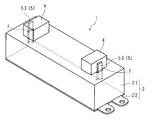
- FIG. 2 is a perspective view illustrating the appearance of the electrical connection box 1.
- the electrical junction box 1 includes a housing 2 forming an outer shell.
- the housing 2 is a rectangular parallelepiped made of an insulating resin, and includes an upper case 21 and a lower case 22. It is desirable that the housing 2 is made of a heat-dissipating resin such as heat-dissipating polypropylene or heat-dissipating polyamide resin.
- the upper case 21 forms, for example, a box having an opening. Inside the upper case 21, for example, a fixing member (not shown) constituting the inner wall of the upper case 21 may be provided.
- the lower case 22 forms, for example, a box body or a dish-shaped lid having an opening, and is provided so as to close the opening of the upper case 21.
- a fixing member (not shown) constituting the inner wall of the lower case 22 may be provided inside the lower case 22.
- the housing 2 forming the outer shell of the electrical connection box 1 is configured.
- the electrical connection box 1 configured in this way is placed in the vicinity of the power storage device 100, for example.
- An electrical component 4 is placed on the outer surface of the housing of the electrical junction box 1, that is, the electrical component 4 is provided so as to be exposed from the electrical junction box 1.
- a connecting bus bar 53 which will be described later, is connected to the electrical component 4 mounted on the outer surface of the housing 2, and the connecting bus bar 53 is the first bus bar 51 or the second bus bar 51 housed in the housing 2. It is connected to the bus bar 52 (see FIG. 3).
- An insertion portion 7 formed of a hole or a notch for inserting the connecting bus bar 53 is formed on the outer surface of the housing 2 on which the electric component 4 is placed.
- the connecting bus bar 53 is provided over the inside and the outside of the housing 2 via the insertion portion 7, and electrically and thermally connects the electric component 4 with the first bus bar 51 or the second bus bar 52.
- the heat generated from the electrical component 4 can be efficiently dissipated to the outside of the electrical junction box 1. Further, since it is not necessary to house the electric component 4 in the electric connection box 1, it is possible to prevent the size of the electric connection box 1 (the size of the housing 2) from becoming large.
- the mounting form of the electric component 4 is not limited to the case where it is mounted on the outer surface of the housing 2, and the electric component 4 is housed inside the housing 2 and provided in the electrical connection box 1. May be good.
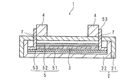
- FIG. 3 is a side sectional view illustrating the inside of the electrical connection box 1.
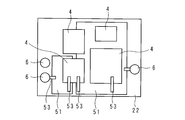
- FIG. 4 is a plan sectional view illustrating the first bus bar 51 and the like inside the electrical connection box 1.
- FIG. 5 is a plan sectional view illustrating the second bus bar 52 and the like inside the electrical connection box 1.
- the bus bar 5 is made of a plate member and is made of a metal having high conductivity and heat transfer coefficient by copper or a copper alloy, and includes a first bus bar 51, a second bus bar 52, and a connected bus bar 53.
- the first bus bar 51 is provided located on the side of the lower case 22 (one side of the housing 2), and the second bus bar 52 is provided located on the side of the upper case 21 (the other side of the housing 2).
- the electrical junction box 1 includes a plate-shaped insulating member 3 provided between the first bus bar 51 and the second bus bar 52.
- the first bus bar 51 is composed of, for example, two plate members, and the first bus bar 51 composed of these two plate members is provided so as to face the bottom surface of the lower case 22. That is, the two plate members constituting the first bus bar 51 are provided side by side on the bottom surface of the lower case 22 forming the box body (on the bottom surface of the housing 2), and are arranged side by side so as to be flush with each other. Has been done.
- the area of the first bus bar 51 that is, the total area of the two plate members constituting the first bus bar 51 is larger than 50% of the area of the bottom surface of the lower case 22 facing the first bus bar 51. ..
- the heat transfer area between the first bus bar 51 and the bottom surface of the lower case 22 is increased, and the heat generated from the electric component 4 is generated. Heat can be efficiently transferred to the lower case 22 via the bus 51, and heat can be dissipated from the lower case 22 to the outside of the electric junction box 1.
- the first bus bar 51 and the electric component 4 are connected by a connecting bus bar 53. Any of the electric components 4 may be provided so as to straddle each of the two plate members constituting the first bus bar 51. That is, the electric component 4 may be connected to two connecting bus bars 53, and each of the two connecting bus bars 53 may be connected to each of the two plate members constituting the first bus bar 51.
- the first bus bar 51 may be connected to the terminal 6 provided on the bottom surface of the lower case 22 via the connecting bus bar 53.
- the first bus bar 51 is composed of two plate members arranged side by side on the bottom surface of the lower case 22, but the present invention is not limited to this.
- the first bus bar 51 may be composed of three or more plate members arranged side by side on the bottom surface of the lower case 22.
- the first bus bar 51 may be composed of a single plate member provided on the bottom surface of the lower case 22.
- the second bus bar 52 is composed of, for example, a single plate member, and is provided so as to face the bottom surface (top surface of the housing 2) of the upper case 21 forming a box body. As described above, a plate-shaped insulating member 3 is interposed between the second bus bar 52 and the first bus bar 51, and the second bus bar 52 is provided on the insulating member 3.
- the area of the second bus bar 52 is smaller than the area of the first bus bar 51. Therefore, in a plan view from the upper case 21 side, a region that does not overlap with the second bus bar 52 is generated in the first bus bar 51.
- the connecting bus bar 51 is located in the area of the first bus bar 51 that does not overlap with the second bus bar 52 in a plan view. By connecting the end portions of the 53, the electric component 4 and the first bus bar 51 can be easily connected.
- the plate thicknesses of the second bus bar 52 and the first bus bar 51 are the same, and the materials of the second bus bar 52 and the first bus bar 51 may be the same. By making the materials of the second bus bar 52 and the first bus bar 51 the same and the plate thickness the same in this way, the second bus bar 52 and the first bus bar 51 are manufactured by punching out from the same sheet metal material. It is possible to reduce the cost of parts.
- the second bus bar 52 and the electric component 4 are connected by a connecting bus bar 53.
- the second bus bar 52 may be connected to the terminal 6 provided on the insulating member 3 via the connecting bus bar 53.
- the second bus bar 52 is composed of a single plate member provided on the insulating member 3, but the present invention is not limited to this.
- the second bus bar 52 may be composed of two or more plate members arranged side by side on the insulating member 3.
- the connecting bus bar 53 is a rod-shaped or plate-shaped extending member having a rectangular cross-sectional shape, and may be made of the same material as the first bus bar 51 and the second bus bar 52.
- the connecting bus bar 53 is provided between the electric component 4 and the first bus bar 51 or the second bus bar 52, and electrically and thermally connects the electric component 4 with the first bus bar 51 or the second bus bar 52. To do. Therefore, the first bus bar 51 and the second bus bar 52 are connected to each other via the electrical component 4 and the connecting bus bar 53.
- the connecting bus bar 53 may have a bent shape depending on the arrangement of the electrical components 4.
- the plate thickness of the connected bus bar 53 is larger than the plate thickness of the first bus bar 51 and the second bus bar 52. Therefore, the difference between the cross-sectional area of the connected bus bar 53 and the cross-sectional area of the first bus bar 51 or the second bus bar 52 in the direction in which the current flows can be reduced, and the connected bus bar 53 and the first bus bar 51 or the second bus bar 52 can be reduced. In the current flowing in, the current density can be leveled.
- connection mode of the connecting bus bar 53 and the electric component 4 is not limited to the one shown in this embodiment.
- the arrangement of the connecting bus bar 53 is appropriately determined based on the arrangement of the electric parts 4 according to the type and the number of the electric parts 4 provided in the electric connection box 1. That is, a laminated structure is formed by the first bus bar 51 and the second bus bar 52 housed in the electric connection box 1, and the first bus bar 51 and the second bus bar 52 are arranged according to the electric circuit composed of the electric components 4 mounted on the electric connection box 1.
- the 1 bus bar 51 or the second bus bar 52 and the electrical component 4 may be connected by a connecting bus bar 53.
- the electrical connection box 1 includes a plate-shaped insulating member 3 provided between the first bus bar 51 and the second bus bar 52. Therefore, the laminated structure is formed by the first bus bar 51, the insulating member 3, and the second bus bar 52.
- the material of the insulating member 3 may be the same as that of the housing 2, that is, the upper case 21 and the lower case 22, and it is desirable that the insulating member 3 is made of a heat-dissipating resin such as heat-dissipating polypropylene or heat-dissipating polyamide resin.
- the housing 2 and the insulator can be molded from the same material such as a resin material, which improves the manufacturability of the electrical junction box 1 and reduces the manufacturing cost. It can be reduced.
- the heat of the second bus bar 52 is made more efficient by making the insulating member 3 and the housing 2 made of the same heat-dissipating resin.
- the heat can be transferred to the first bus bar 51, and heat can be efficiently dissipated to the outside of the electric junction box 1 from the upper case 21 which is in close contact with the first bus bar 51.
- the second bus bar 52 can be formed in a laminated structure, even if the heat transfer path from the second bus bar 52 to the outer peripheral surface of the housing 2 becomes long, the second bus bar The heat can be efficiently dissipated through the insulating member 3 and the first bus bar 51 laminated on the bus bar 52, and the heat dissipation of the electric junction box 1 can be improved.
- the bus bar 5 housed in the housing 2 of the electrical connection box 1 is divided into the first bus bar 51 and the second bus bar 52, the first bus bar 51 is arranged on the lower case 22 side, and the second bus bar 51 is arranged.
- the bus bar 52 By arranging the bus bar 52 on the side of the upper case 21 and stacking the first bus bar 51 and the second bus bar 52, the size of the housing 2 of the electrical connection box 1 can be reduced.
- the degree of freedom of arrangement in mounting the electric component 4 is improved. Can be done.
- the insertion portion 7 by a through hole or the like provided on the outer surface (top surface of the housing 2) of the upper case 21 is inserted.
- a connecting bus bar 53 is provided via the connection bus bar 53, and the electrical component 4 can be electrically connected to the first bus bar 51 or the second bus bar 52 by the connecting bus bar 53 inserted through the insertion portion 7.
- the present embodiment by interposing a plate-shaped insulating member 3 between the first bus bar 51 and the second bus bar 52, the bottom surfaces of the first bus bar 51, the insulating member 3, the second bus bar 52, and the lower case 22 ( A laminated structure is formed by the bottom surface of the housing 2. On top of that, by forming the lower case 22 (housing 2) and the insulating member 3 with the same heat-dissipating resin, the heat-dissipating property of the electric junction box 1 can be improved.
Landscapes
- Engineering & Computer Science (AREA)
- Microelectronics & Electronic Packaging (AREA)
- Architecture (AREA)
- Civil Engineering (AREA)
- Structural Engineering (AREA)
- Mechanical Engineering (AREA)
- Connection Or Junction Boxes (AREA)
Abstract
電気接続箱(1)は、車両(C)に搭載される電気接続箱であって、前記車両に搭載される蓄電装置(100)又は車載負荷(101)に、電気的に接続される電気部品(4)と、前記電気部品に、電気的に接続されるバスバ(5)と、前記バスバを収容する筐体(2)とを備え、前記バスバは、前記筐体の一面の側に位置する第1バスバ(51)と、前記筐体の他面の側に位置する第2バスバ(52)と、前記第1バスバ又は第2バスバと、前記電気部品とを電気的に接続する連結バスバ(53)とを含み、前記第1バスバ及び前記第2バスバにより、積層構造が形成される。
Description
本開示は、電気接続箱に関する。
本出願は、2019年12月17日出願の日本出願第2019-227644号に基づく優先権を主張し、前記日本出願に記載された全ての記載内容を援用するものである。
本出願は、2019年12月17日出願の日本出願第2019-227644号に基づく優先権を主張し、前記日本出願に記載された全ての記載内容を援用するものである。
車載に搭載され、車載バッテリから車内の各車載負荷に電力を供給する電線は、電機接続箱(ジャンクションボックス)に一旦接続され、当該電機接続箱を介して車載負荷夫々に接続される(例えば、特許文献1)。特許文献1の電機接続箱には、リレー及び当該リレーが固定される箱本体を備える。
本開示の一態様に係る電気接続箱は、車両に搭載される電気接続箱であって、前記車両に搭載される蓄電装置又は車載負荷に、電気的に接続される電気部品と、前記電気部品に、電気的に接続されるバスバと、前記バスバを収容する筐体とを備え、前記バスバは、前記筐体の一面の側に位置する第1バスバと、前記筐体の他面の側に位置する第2バスバと、前記第1バスバ又は第2バスバと、前記電気部品とを電気的に接続する連結バスバとを含み、前記第1バスバ及び前記第2バスバにより、積層構造が形成される。
[本開示が解決しようとする課題]
電機接続箱にはリレー等の電気部品が収納され、当該電気部品の部品サイズが大きくなった場合、電機接続箱のサイズも大型化することが懸念されるところ、特許文献1の電機接続箱においては、このような電機接続箱の大型化に対する考慮がされていないという問題点がある。
電機接続箱にはリレー等の電気部品が収納され、当該電気部品の部品サイズが大きくなった場合、電機接続箱のサイズも大型化することが懸念されるところ、特許文献1の電機接続箱においては、このような電機接続箱の大型化に対する考慮がされていないという問題点がある。
本開示は、電気部品を収納する電気接続箱が、大型化することを抑制することを目的とする。
[本開示の効果]
本開示の一態様によれば、電気部品を収納する電気接続箱が、大型化することを抑制することができる。
本開示の一態様によれば、電気部品を収納する電気接続箱が、大型化することを抑制することができる。
[本開示の実施形態の説明]
最初に本開示の実施態様を列挙して説明する。また、以下に記載する実施形態の少なくとも一部を任意に組み合わせてもよい。
最初に本開示の実施態様を列挙して説明する。また、以下に記載する実施形態の少なくとも一部を任意に組み合わせてもよい。
(1)本開示の一態様に係る電気接続箱は、車両に搭載される電気接続箱であって、前記車両に搭載される蓄電装置又は車載負荷に、電気的に接続される電気部品と、前記電気部品に、電気的に接続されるバスバと、前記バスバを収容する筐体とを備え、前記バスバは前記筐体の一面の側に位置する第1バスバと、前記筐体の他面の側に位置する第2バスバと、前記第1バスバ又は第2バスバと、前記電気部品とを電気的に接続する連結バスバとを含み、前記第1バスバ及び前記第2バスバにより、積層構造が形成される。
本態様にあたっては、電気接続箱の筐体に収納されるバスバを第1バスバ及び第2バスバに分割し、これら第1バスバ及び第2バスバを積層することにより、電気接続箱の筐体のサイズを小さくすることができ、電気接続箱が大型化することを抑制することができる。
(2)本開示の一態様に係る電気接続箱は、前記連結バスバの板厚は、前記第1バスバ及び前記第2バスバの板厚よりも大きい。
本態様にあたっては、連結バスバの板厚は、第1バスバ及び第2バスバの板厚よりも大きくしてある。連結バスバの面積が、第1バスバ及び第2バスバの面積よりも小さい場合であっても、電流が流れる方向における連結バスバの断面積と、第1バスバ又は第2バスバの断面積の差異を小さくすることができる。従って、連結バスバと、第1バスバ又は第2バスバとの接合部における電気抵抗値の差異を小さくすることができ、連結バスバと、第1バスバ又は第2バスバにて流れる電流において、電流密度を平準化させる傾向とすることができる。
(3)本開示の一態様に係る電気接続箱は、前記第1バスバの面積は、前記第2バスバの面積よりも大きい。
本態様にあたっては、第1バスバは筐体の一面に対向して設けられており、第1バスバの面積は、第2バスバの面積よりも大きくしてあるため、電気部品が発生した熱を、第1バスバから当該筐体の一面に効率的に伝熱させ、筐体を介して外部に効率的に放熱することができる。
(4)本開示の一態様に係る電気接続箱は、前記第1バスバと前記第2バスバとの間には、前記第1バスバの面積よりも大きい面積の絶縁部材が設けられており、前記絶縁部材及び前記筐体は、同じ材質で成形されており、前記第1バスバ、前記絶縁部材及び前記第2バスバにより、積層構造が形成される。
本態様にあたっては、第1バスバと第2バスバとの間に介在する絶縁体は、第1バスバの面積よりも大きくしてあるため、第1バスバと第2バスバとを確実に絶縁することができる。更に、当該絶縁体の材質は、筐体の材質と同じにしてあるため、同一の樹脂材等の材料により筐体及び絶縁体を成形することができ、電気接続箱の製造性の向上及び製造コストの低減を図ることができる。
(5)本開示の一態様に係る電気接続箱は、前記第1バスバ及び前記第2バスバの板厚は、同じである。
本態様にあたっては、第1バスバ及び第2バスバの板厚は、同じにしてあるため、同一の板金材から、打ち抜き等を行うことにより、第1バスバ及び第2バスバを成形することができ、電気接続箱の製造性の向上及び製造コストの低減を図ることができる。
(6)本開示の一態様に係る電気接続箱は、前記筐体の一面に対向する前記第1バスバの面の面積は、前記筐体の一面の面積の50%よりも大きい。
本態様にあたっては、筐体の一面に対向する第1バスバの面の面積は、筐体の一面の面積の50%よりも大きくしてあるので、放熱性を担保しつつ、電気接続箱の筐体のサイズを小さくすることができ、電気接続箱の大型化を抑制することができる。
(7)本開示の一態様に係る電気接続箱は、前記電気部品は、前記筐体の外面に設けられており、前記筐体の外面には、前記電気部品に接続される前記連結バスバが挿通される挿通部が、形成されている。
本態様にあたっては、複数の電気部品に内のいずれかの電気部品を筐体の外面に設けることにより、当該いずれかの電気部品を電気接続箱から露出させ、放熱性を向上させると共に、当該いずれかの電気部品を筐体内に収容することを不要とし、電気接続箱の筐体サイズが大型化することを抑制することができる。筐体の外面には、いずれかの電気部品に接続される連結バスバが挿通される挿通部が、形成されているため、当該いずれかの電気部品と、筐体内に収容されている第1バスバ又は第2バスバとを、当該挿通部に挿通される連結バスバによって、確実に接続することができる。
(8)本開示の一態様に係る電気接続箱は、前記電気部品は、高電圧用リレー又は高電圧用ヒューズを含み、前記バスバは、高電圧用のバスバである。
本態様にあたっては、高電圧用リレー又は高電圧用ヒューズを用いることにより、電気部品が大型化する場合であっても、筐体サイズが大型化することを抑制した高圧用の電気接続箱を提供することができる。
[本開示の実施形態の詳細]
本開示の実施態様に係る電気接続箱1の具体例を以下に図面を参照しつつ説明する。なお、本開示はこれらの例示に限定されるものではなく、請求の範囲によって示され、請求の範囲と均等の意味および範囲内でのすべての変更が含まれることが意図される。
本開示の実施態様に係る電気接続箱1の具体例を以下に図面を参照しつつ説明する。なお、本開示はこれらの例示に限定されるものではなく、請求の範囲によって示され、請求の範囲と均等の意味および範囲内でのすべての変更が含まれることが意図される。
(実施形態1)
図1は、実施形態1に係る電気接続箱1が搭載された車両Cを示す概略図である。本実施形態における電気接続箱1は、車両Cに搭載され、同様に車両Cに搭載される蓄電装置100と車載負荷101との間に介在して設けられる。蓄電装置100及び車載負荷101は、電気接続箱1を介して、電線102により電気的に接続されている。
図1は、実施形態1に係る電気接続箱1が搭載された車両Cを示す概略図である。本実施形態における電気接続箱1は、車両Cに搭載され、同様に車両Cに搭載される蓄電装置100と車載負荷101との間に介在して設けられる。蓄電装置100及び車載負荷101は、電気接続箱1を介して、電線102により電気的に接続されている。
本実施形態にて、車載負荷101は一つとして記載してあるが、車載負荷101の個数は単数に限定されない。車両Cに搭載される車載負荷101は、複数であってもよく、電気接続箱1の内部に、又は電気接続箱1と複数の車載負荷101との間に分岐部を設け、当該分岐部により蓄電装置100の正極に接続される電線102を分岐し、分岐した電線102を複数の車載負荷101夫々に接続するものであってもよい。
本実施形態にて、電気接続箱1は蓄電装置100の正極側に接続してあるが、これに限定されない。電気接続箱1は蓄電装置100の負極側に接続するものであってもよい。又は、電気接続箱1は蓄電装置100の正極側及び負極側の夫々に接続されるものであってもよい。
蓄電装置100は、例えば、鉛バッテリ又は、リチウムイオン電池等のEV(Electric Vehicle)用の高圧バッテリである。
電気接続箱1は、電気部品4を備える。電気部品4は、例えばヒューズ42、リレー41を含む。リレー41は、機械式リレー、又は半導体リレーであってもよい。電気部品4に含まれるヒューズ42及びリレー41は、バスバ5により接続され、直列回路を構成する。これらヒューズ42及びリレー41は、EV用の高圧バッテリに対応した高電圧用のヒューズ42(高電圧用ヒューズ)及びリレー41(高電圧用リレー)であってもよい。リレー41と車載負荷101とは、バスバ5を介して接続される。ヒューズ42と蓄電装置100とは、バスバ5を介して接続される。リレー41は、車両Cに搭載される電力制御系のECU(図示せず)と信号線により通信可能に接続され、当該ECUから出力される信号に応じて、オン又はオフにされる。
図2は、電気接続箱1の外観を略示した斜視図である。電気接続箱1は、外郭を成す筐体2を備える。筐体2は、絶縁性の樹脂製による直方体を成し、アッパケース21及びロワケース22を含む。筐体2は、例えば放熱性ポリプロピレン、放熱ポリアミド樹脂等による放熱性樹脂製であることが望ましい。
アッパケース21は、例えば、開口部を有する箱体を成す。アッパケース21の内側には、例えば当該アッパケース21の内壁を構成する固定部材(図示せず)が設けられているものであってもよい。
ロワケース22は、例えば、開口部を有する箱体又は皿状の蓋体を成し、アッパケース21の開口部を塞ぐように設けられる。ロワケース22の内側には、例えば当該ロワケース22内壁を構成する固定部材(図示せず)が設けられているものであってもよい。
アッパケース21の開口部にロワケース22が係合することにより、電気接続箱1の外郭を成す筐体2が構成される。このように構成される電気接続箱1は、例えば、蓄電装置100の近傍に載置される。
電気接続箱1の筐体の外面上には、電気部品4が載置されており、すなわち電気部品4は、電気接続箱1から露出して設けられている。筐体2の外面上に載置された電気部品4には、後述する連結バスバ53が接続されており、当該連結バスバ53は、筐体2内に収容されている第1バスバ51又は第2バスバ52(図3参照)に接続されている。電気部品4が載置される筐体2の外面には、連結バスバ53を挿通するための孔部又は切欠き等により構成される挿通部7が形成されている。連結バスバ53は、挿通部7を介して、筐体2の内部及び外部に亘って設けられ、電気部品4と、第1バスバ51又は第2バスバ52とを電気的及び熱的に接続する。
電気部品4を筐体2の外面上に載置し、電気接続箱1から露出して設けることにより、電気部品4からの発熱を効率的に電気接続箱1の外部に放熱することができる。更に電気接続箱1内に電気部品4を収容することを不要とすることができるため、電気接続箱1のサイズ(筐体2のサイズ)が大型化することを抑制することができる。電気部品4の実装形態は、筐体2の外面上に載置される場合に限定されず、電気部品4は、筐体2の内部に収容されて電気接続箱1に設けられるものであってもよい。
図3は、電気接続箱1の内部を略示する側断面図である。図4は、電気接続箱1の内部における第1バスバ51等を略示する平断面図である。図5は、電気接続箱1の内部における第2バスバ52等を略示する平断面図である。
バスバ5は、板部材により構成され、銅又は銅合金等による導電率及び熱伝達率が高い金属製であり、第1バスバ51、第2バスバ52及び連結バスバ53を含む。第1バスバ51はロワケース22の側(筐体2の一面側)に位置して設けられており、第2バスバ52はアッパケース21の側(筐体2の他面側)に位置して設けられている。電気接続箱1は、第1バスバ51及び第2バスバ52の間に設けられた板状の絶縁部材3を備える。
第1バスバ51は、例えば、2枚の板部材により構成され、これら2枚の板部材から成る第1バスバ51は、ロワケース22の底面に対向して設けられている。すなわち、第1バスバ51を構成する2枚の板部材夫々は、箱体を成すロワケース22の底面上(筐体2の底面上)に並んで設けられており、面一となるように並設されている。
第1バスバ51の面積、すなわち第1バスバ51を構成する2枚の板部材夫々の面積の合算値は、第1バスバ51に対向するロワケース22の底面の面積の50%よりも大きくしてある。第1バスバ51の面積をロワケース22の底面の面積の50%よりも大きくすることにより、第1バスバ51とロワケース22の底面との伝熱面積を大きくし、電気部品4からの発熱を、第1バスバ51を介してロワケース22に効率的に伝熱させ、ロワケース22から電気接続箱1の外部に放熱することができる。
第1バスバ51と電気部品4とは、連結バスバ53によって接続されている。いずれかの電気部品4は、第1バスバ51を構成する2枚の板部材夫々に跨って、設けられるものであってもよい。すなわち当該電気部品4は、2つの連結バスバ53に接続され、これら2つの連結バスバ53夫々は、第1バスバ51を構成する2枚の板部材夫々に接続されるものであってもよい。第1バスバ51は、連結バスバ53を介して、ロワケース22の底面上に設けられた端子6と接続されるものであってもよい。
本実施形態において、第1バスバ51は、ロワケース22の底面上に並設される2枚の板部材により構成されるとしたが、これに限定されない。第1バスバ51は、ロワケース22の底面上に並設される3枚以上の板部材により構成されるものであってもよい。又は、第1バスバ51は、ロワケース22の底面上に設けられる単一の板部材により構成されるものであってもよい。
第2バスバ52は、例えば、単一の板部材により構成され、箱体を成すアッパケース21の底面(筐体2の天面)に対向して設けられている。上述のとおり、第2バスバ52及び第1バスバ51との間には、板状の絶縁部材3が介在しており、第2バスバ52は当該絶縁部材3上に設けられている。
第2バスバ52の面積は、第1バスバ51の面積よりも小さくしてある。従って、アッパケース21側からの平面視にて、第1バスバ51において、第2バスバ52とは重ならない領域が発生する。例えばアッパケース21の外面に載置した電気部品4と第1バスバ51とを連結バスバ53により接続する場合、平面視にて第2バスバ52と重ならない第1バスバ51の領域に、当該連結バスバ53の端部を接続することにより、電気部品4と第1バスバ51とを簡易に接続することができる。
第2バスバ52及び第1バスバ51の板厚は、同じであり、第2バスバ52及び第1バスバ51の材質は同じものであってもよい。このように第2バスバ52及び第1バスバ51の材質を同じにし、かつ板厚を同じにすることにより、第2バスバ52及び第1バスバ51を同一の板金材から抜き打ち加工等して製造することができ、部品コストの削減を図ることができる。
第2バスバ52と電気部品4とは、連結バスバ53によって接続されている。第2バスバ52は、連結バスバ53を介して、絶縁部材3上に設けられた端子6と接続されるものであってもよい。
本実施形態において、第2バスバ52は、絶縁部材3上に設けられた単一の板部材により構成されるとしたが、これに限定されない。第2バスバ52は、絶縁部材3上に並設される2枚以上の板部材により構成されるものであってもよい。
連結バスバ53は、矩形状の断面形状からなる棒状又は板状の延在部材であり、第1バスバ51及び第2バスバ52と同じ材質であってもよい。連結バスバ53は、電気部品4と、第1バスバ51又は第2バスバ52との間に設けられ、当該電気部品4と、第1バスバ51又は第2バスバ52とを電気的及び熱的に接続する。従って、第1バスバ51と第2バスバ52とは、電気部品4及び連結バスバ53を介して接続される。連結バスバ53は、電気部品4の配置に応じて、屈曲された形状のものであってもよい。
連結バスバ53の板厚は、第1バスバ51及び第2バスバ52の板厚よりも大きくしてある。従って、電流が流れる方向における連結バスバ53の断面積と、第1バスバ51又は第2バスバ52の断面積の差異を小さくすることができ、連結バスバ53と、第1バスバ51又は第2バスバ52にて流れる電流において、電流密度を平準化させる傾向とすることができる。
本実施形態にて図示するものは例示であり、連結バスバ53及び電気部品4の接続態様は、本実施形態にて図示されるものに限定されない。連結バスバ53の配置は、電気接続箱1に備えられる電気部品4の種類、個数に応じた当該電気部品4の配置に基づき、適宜、決定される。すなわち、電気接続箱1に収容される第1バスバ51及び第2バスバ52によって積層構造が形成されており、電気接続箱1に搭載される電気部品4により構成される電気回路に応じて、第1バスバ51又は第2バスバ52と、電気部品4とが、連結バスバ53によって接続されるものであればよい。
電気接続箱1は、第1バスバ51及び第2バスバ52の間に設けられた板状の絶縁部材3を備える。従って、第1バスバ51、絶縁部材3及び第2バスバ52によって積層構造が形成される。絶縁部材3の材質は、筐体2、すなわちアッパケース21及びロワケース22と同じ材質であってもよく、例えば放熱性ポリプロピレン、放熱ポリアミド樹脂等による放熱性樹脂製であることが望ましい。
絶縁部材3と筐体2とを同じ材質とすることにより、同一の樹脂材等の材料により筐体2及び絶縁体を成形することができ、電気接続箱1の製造性の向上及び製造コストの低減を図ることができる。
第1バスバ51、絶縁部材3及び第2バスバ52によって積層構造が形成されているので、絶縁部材3と筐体2とを同じ放熱性樹脂製とすることにより、第2バスバ52の熱を効率的に第1バスバ51に伝熱させ、第1バスバ51に密接するアッパケース21から電気接続箱1の外部に効率的に放熱することができる。すなわち、第1バスバ51、絶縁部材3及び第2バスバ52を積層構造とすることにより、第2バスバ52から筐体2の外周面までの伝熱経路が長くなるものであっても、第2バスバ52に積層される絶縁部材3及び第1バスバ51を介して効率的に放熱でき、電気接続箱1の放熱性を向上させることができる。
本実施形態によれば、電気接続箱1の筐体2に収納されるバスバ5を第1バスバ51及び第2バスバ52に分割し、第1バスバ51をロワケース22の側に配置し、第2バスバ52をアッパケース21の側に配置して、これら第1バスバ51及び第2バスバ52を積層することにより、電気接続箱1の筐体2のサイズを小さくすることができる。
第1バスバ51又は第2バスバ52と、電気接続箱1に実装される電気部品4とは、連結バスバ53にて接続することにより、当該電気部品4の実装における配置の自由度を向上させることができる。電気部品4を筐体2(アッパケース21)の外面に載置する実装形態においては、例えば、アッパケース21の外面(筐体2の天面)に設けられた貫通孔等による挿通部7を介して連結バスバ53を設け、当該挿通部7に挿通された連結バスバ53によって電気部品4と、第1バスバ51又は第2バスバ52とを電気的に接続することができる。
本実施形態によれば、第1バスバ51及び第2バスバ52の間に板状の絶縁部材3を介在させることにより、第1バスバ51、絶縁部材3、第2バスバ52及びロワケース22の底面(筐体2の底面)による積層構造が形成される。その上で、ロワケース22(筐体2)及び絶縁部材3を同じ放熱性樹脂製にて形成することにより、電気接続箱1の放熱性を向上させることができる。
今回開示された実施形態はすべての点で例示であって、制限的なものではないと考えられるべきである。本発明の範囲は、上記した意味ではなく、請求の範囲によって示され、請求の範囲と均等の意味及び範囲内でのすべての変更が含まれることが意図される。
C 車両
1 電気接続箱
2 筐体
21 アッパケース
22 ロワケース
3 絶縁部材
4 電気部品
41 リレー
42 ヒューズ
5 バスバ
51 第1バスバ
52 第2バスバ
53 連結バスバ
6 端子
7 挿通部
100 蓄電装置
101 車載負荷
102 電線
1 電気接続箱
2 筐体
21 アッパケース
22 ロワケース
3 絶縁部材
4 電気部品
41 リレー
42 ヒューズ
5 バスバ
51 第1バスバ
52 第2バスバ
53 連結バスバ
6 端子
7 挿通部
100 蓄電装置
101 車載負荷
102 電線
Claims (8)
- 車両に搭載される電気接続箱であって、
前記車両に搭載される蓄電装置又は車載負荷に、電気的に接続される電気部品と、
前記電気部品に、電気的に接続されるバスバと、
前記バスバを収容する筐体とを備え、
前記バスバは、
前記筐体の一面の側に位置する第1バスバと、
前記筐体の他面の側に位置する第2バスバと、
前記第1バスバ又は第2バスバと、前記電気部品とを電気的に接続する連結バスバとを含み、
前記第1バスバ及び前記第2バスバにより、積層構造が形成される
電気接続箱。 - 前記連結バスバの板厚は、前記第1バスバ及び前記第2バスバの板厚よりも大きい
請求項1に記載の電気接続箱。 - 前記第1バスバの面積は、前記第2バスバの面積よりも大きい
請求項1又は請求項2に記載の電気接続箱。 - 前記第1バスバと前記第2バスバとの間には、前記第1バスバの面積よりも大きい面積の絶縁部材が設けられており、
前記絶縁部材及び前記筐体は、同じ材質で成形されており、
前記第1バスバ、前記絶縁部材及び前記第2バスバにより、積層構造が形成される
請求項1から請求項3のいずれか1項に記載の電気接続箱。 - 前記第1バスバ及び前記第2バスバの板厚は、同じである
請求項1から請求項4のいずれか1項に記載の電気接続箱。 - 前記筐体の一面に対向する前記第1バスバの面の面積は、前記筐体の一面の面積の50%よりも大きい
請求項1から請求項5のいずれか1項に記載の電気接続箱。 - 前記電気部品は、前記筐体の外面に設けられており、
前記筐体の外面には、前記電気部品に接続される前記連結バスバが挿通される挿通部が、形成されている
請求項1から請求項6のいずれか1項に記載の電気接続箱。 - 前記電気部品は、高電圧用リレー又は高電圧用ヒューズを含み、
前記バスバは、高電圧用のバスバである
請求項1から請求項7のいずれか1項に記載の電気接続箱。
Applications Claiming Priority (2)
| Application Number | Priority Date | Filing Date | Title |
|---|---|---|---|
| JP2019227644A JP7283369B2 (ja) | 2019-12-17 | 2019-12-17 | 電気接続箱 |
| JP2019-227644 | 2019-12-17 |
Publications (1)
| Publication Number | Publication Date |
|---|---|
| WO2021124841A1 true WO2021124841A1 (ja) | 2021-06-24 |
Family
ID=76431775
Family Applications (1)
| Application Number | Title | Priority Date | Filing Date |
|---|---|---|---|
| PCT/JP2020/044404 Ceased WO2021124841A1 (ja) | 2019-12-17 | 2020-11-30 | 電気接続箱 |
Country Status (2)
| Country | Link |
|---|---|
| JP (1) | JP7283369B2 (ja) |
| WO (1) | WO2021124841A1 (ja) |
Citations (2)
| Publication number | Priority date | Publication date | Assignee | Title |
|---|---|---|---|---|
| JP2001286032A (ja) * | 2000-03-31 | 2001-10-12 | Sumitomo Wiring Syst Ltd | ジャンクションボックスの内部回路接続方法および接続構造 |
| JP2007028896A (ja) * | 2006-08-07 | 2007-02-01 | Sumitomo Wiring Syst Ltd | 車載用電気接続箱の組立方法 |
Family Cites Families (2)
| Publication number | Priority date | Publication date | Assignee | Title |
|---|---|---|---|---|
| JP4292958B2 (ja) * | 2003-11-13 | 2009-07-08 | 住友電装株式会社 | 回路構成体及び配電ユニット |
| WO2018002988A1 (ja) * | 2016-06-27 | 2018-01-04 | 日立化成株式会社 | ポリアミドイミド樹脂組成物及び塗料 |
-
2019
- 2019-12-17 JP JP2019227644A patent/JP7283369B2/ja active Active
-
2020
- 2020-11-30 WO PCT/JP2020/044404 patent/WO2021124841A1/ja not_active Ceased
Patent Citations (2)
| Publication number | Priority date | Publication date | Assignee | Title |
|---|---|---|---|---|
| JP2001286032A (ja) * | 2000-03-31 | 2001-10-12 | Sumitomo Wiring Syst Ltd | ジャンクションボックスの内部回路接続方法および接続構造 |
| JP2007028896A (ja) * | 2006-08-07 | 2007-02-01 | Sumitomo Wiring Syst Ltd | 車載用電気接続箱の組立方法 |
Also Published As
| Publication number | Publication date |
|---|---|
| JP7283369B2 (ja) | 2023-05-30 |
| JP2021097504A (ja) | 2021-06-24 |
Similar Documents
| Publication | Publication Date | Title |
|---|---|---|
| JP7193005B2 (ja) | 電気接続箱 | |
| JP6180848B2 (ja) | 組電池のブスバおよび組電池 | |
| JP2020127302A (ja) | 電気接続箱 | |
| CN113170596B (zh) | 电路结构体 | |
| CN112956068A (zh) | 电池模块 | |
| US11731572B2 (en) | Electrical junction box | |
| JP6900821B2 (ja) | 電池パック | |
| JP5601221B2 (ja) | 組電池用バスバー及びバスバーモジュール | |
| JP7552412B2 (ja) | 電気接続箱 | |
| JP7581943B2 (ja) | 電気接続箱 | |
| JP7283369B2 (ja) | 電気接続箱 | |
| JP7268441B2 (ja) | 蓄電装置 | |
| KR20190095045A (ko) | 배터리 버스바 장치, 이를 이용한 배터리 버스바 체결 구조 및 이를 구비한 배터리 팩 | |
| JP7099807B2 (ja) | 電池パック | |
| US11955788B2 (en) | Electrical connection box | |
| JP7243680B2 (ja) | 接続端子、および、それを含む端子モジュール | |
| JP7195726B2 (ja) | 蓄電装置 | |
| US20250372981A1 (en) | Electrical connection unit | |
| WO2021006109A1 (ja) | 電気接続箱 | |
| US20260024978A1 (en) | Electrical connection unit | |
| US20250374488A1 (en) | Electrical connection unit | |
| US20250372930A1 (en) | Electrical connection unit | |
| US20250105608A1 (en) | Electrical connection box | |
| US20250112447A1 (en) | Electrical connection box | |
| US20250372971A1 (en) | Electrical connection unit |
Legal Events
| Date | Code | Title | Description |
|---|---|---|---|
| 121 | Ep: the epo has been informed by wipo that ep was designated in this application |
Ref document number: 20900744 Country of ref document: EP Kind code of ref document: A1 |
|
| NENP | Non-entry into the national phase |
Ref country code: DE |
|
| 122 | Ep: pct application non-entry in european phase |
Ref document number: 20900744 Country of ref document: EP Kind code of ref document: A1 |