WO2021124466A1 - コンプレッサおよび該コンプレッサを備えるターボチャージャ - Google Patents
コンプレッサおよび該コンプレッサを備えるターボチャージャ Download PDFInfo
- Publication number
- WO2021124466A1 WO2021124466A1 PCT/JP2019/049497 JP2019049497W WO2021124466A1 WO 2021124466 A1 WO2021124466 A1 WO 2021124466A1 JP 2019049497 W JP2019049497 W JP 2019049497W WO 2021124466 A1 WO2021124466 A1 WO 2021124466A1
- Authority
- WO
- WIPO (PCT)
- Prior art keywords
- flow path
- wall surface
- scroll
- impeller
- side flow
- Prior art date
Links
Images


Classifications
-
- F—MECHANICAL ENGINEERING; LIGHTING; HEATING; WEAPONS; BLASTING
- F04—POSITIVE - DISPLACEMENT MACHINES FOR LIQUIDS; PUMPS FOR LIQUIDS OR ELASTIC FLUIDS
- F04D—NON-POSITIVE-DISPLACEMENT PUMPS
- F04D29/00—Details, component parts, or accessories
- F04D29/40—Casings; Connections of working fluid
- F04D29/42—Casings; Connections of working fluid for radial or helico-centrifugal pumps
- F04D29/44—Fluid-guiding means, e.g. diffusers
- F04D29/441—Fluid-guiding means, e.g. diffusers especially adapted for elastic fluid pumps
-
- F—MECHANICAL ENGINEERING; LIGHTING; HEATING; WEAPONS; BLASTING
- F02—COMBUSTION ENGINES; HOT-GAS OR COMBUSTION-PRODUCT ENGINE PLANTS
- F02B—INTERNAL-COMBUSTION PISTON ENGINES; COMBUSTION ENGINES IN GENERAL
- F02B37/00—Engines characterised by provision of pumps driven at least for part of the time by exhaust
- F02B37/12—Control of the pumps
- F02B37/16—Control of the pumps by bypassing charging air
- F02B37/162—Control of the pumps by bypassing charging air by bypassing, e.g. partially, intake air from pump inlet to pump outlet
-
- F—MECHANICAL ENGINEERING; LIGHTING; HEATING; WEAPONS; BLASTING
- F04—POSITIVE - DISPLACEMENT MACHINES FOR LIQUIDS; PUMPS FOR LIQUIDS OR ELASTIC FLUIDS
- F04D—NON-POSITIVE-DISPLACEMENT PUMPS
- F04D17/00—Radial-flow pumps, e.g. centrifugal pumps; Helico-centrifugal pumps
- F04D17/08—Centrifugal pumps
- F04D17/10—Centrifugal pumps for compressing or evacuating
-
- F—MECHANICAL ENGINEERING; LIGHTING; HEATING; WEAPONS; BLASTING
- F04—POSITIVE - DISPLACEMENT MACHINES FOR LIQUIDS; PUMPS FOR LIQUIDS OR ELASTIC FLUIDS
- F04D—NON-POSITIVE-DISPLACEMENT PUMPS
- F04D27/00—Control, e.g. regulation, of pumps, pumping installations or pumping systems specially adapted for elastic fluids
- F04D27/02—Surge control
- F04D27/0207—Surge control by bleeding, bypassing or recycling fluids
- F04D27/0215—Arrangements therefor, e.g. bleed or by-pass valves
-
- F—MECHANICAL ENGINEERING; LIGHTING; HEATING; WEAPONS; BLASTING
- F04—POSITIVE - DISPLACEMENT MACHINES FOR LIQUIDS; PUMPS FOR LIQUIDS OR ELASTIC FLUIDS
- F04D—NON-POSITIVE-DISPLACEMENT PUMPS
- F04D29/00—Details, component parts, or accessories
- F04D29/40—Casings; Connections of working fluid
- F04D29/42—Casings; Connections of working fluid for radial or helico-centrifugal pumps
- F04D29/4206—Casings; Connections of working fluid for radial or helico-centrifugal pumps especially adapted for elastic fluid pumps
- F04D29/4213—Casings; Connections of working fluid for radial or helico-centrifugal pumps especially adapted for elastic fluid pumps suction ports
-
- F—MECHANICAL ENGINEERING; LIGHTING; HEATING; WEAPONS; BLASTING
- F05—INDEXING SCHEMES RELATING TO ENGINES OR PUMPS IN VARIOUS SUBCLASSES OF CLASSES F01-F04
- F05D—INDEXING SCHEME FOR ASPECTS RELATING TO NON-POSITIVE-DISPLACEMENT MACHINES OR ENGINES, GAS-TURBINES OR JET-PROPULSION PLANTS
- F05D2220/00—Application
- F05D2220/40—Application in turbochargers
-
- Y—GENERAL TAGGING OF NEW TECHNOLOGICAL DEVELOPMENTS; GENERAL TAGGING OF CROSS-SECTIONAL TECHNOLOGIES SPANNING OVER SEVERAL SECTIONS OF THE IPC; TECHNICAL SUBJECTS COVERED BY FORMER USPC CROSS-REFERENCE ART COLLECTIONS [XRACs] AND DIGESTS
- Y02—TECHNOLOGIES OR APPLICATIONS FOR MITIGATION OR ADAPTATION AGAINST CLIMATE CHANGE
- Y02T—CLIMATE CHANGE MITIGATION TECHNOLOGIES RELATED TO TRANSPORTATION
- Y02T10/00—Road transport of goods or passengers
- Y02T10/10—Internal combustion engine [ICE] based vehicles
- Y02T10/12—Improving ICE efficiencies
Definitions
- the present disclosure relates to a compressor and a turbocharger including the compressor.
- a centrifugal compressor of a turbocharger for a passenger car is operated near the surging line, which is the operating limit on the small flow rate side, when the engine in a low speed state is suddenly accelerated.
- the centrifugal compressor is operated after securing a predetermined margin with respect to the surging line, but a bypass valve may be used as a fail-safe device for dynamically avoiding surging.
- the bypass valve has a function of opening and closing the bypass flow path connecting the outlet side (scroll flow path on the downstream side of the impeller) and the inlet side (supply flow path on the upstream side of the impeller) of the compressor.
- the bypass valve closes the bypass flow path.
- the bypass valve opens the bypass flow path to allow the compressed fluid flowing through the outlet side of the compressor.
- the surge margin is secured by returning the fluid to the inlet side of the compressor via the bypass flow path and lowering the boost pressure of the compressor.
- bypass flow path also leads to an increase in pressure loss.
- a cavity portion communicating with the scroll flow path is formed in the bypass flow path. If a large amount of fluid flowing through the scroll flow path flows into the cavity, the scroll flow path is moved when the flow flowing into the cavity forms a swirl and then tries to return to the scroll flow path again. It may interfere with the flowing fluid and cause a large pressure loss, which may reduce the efficiency of the compressor.
- the compressor provided with the bypass flow path and the bypass valve may have an efficiency reduced by about 2 to 3% at the maximum output point of the engine as compared with a configuration in which the bypass flow path and the bypass valve are not provided. This amount of decrease in efficiency corresponds to approximately 10% of the loss in the entire compressor.
- Patent Document 1 proposes to form the surface of the valve body of the bypass valve in a shape along the inner wall of the scroll flow path of the compressor. With such a structure, it is possible to suppress an increase in pressure loss due to the inflow of the flow into the bypass flow path.
- an object of at least one embodiment of the present disclosure is a compressor capable of suppressing an increase in pressure loss of the compressor while suppressing complication of the shape of the valve body of the bypass valve, and the compressor. It is to provide a turbocharger to prepare.
- the compressor according to the present disclosure is with an impeller A housing configured to rotatably house the impeller.
- a bypass valve provided in the bypass flow path and having a valve body capable of opening and closing the bypass flow path is provided.
- the valve body is configured to partition the bypass flow path into an inlet side flow path having a communication port communicating with the scroll flow path and an outlet side flow path communicating with the intake flow path in a fully closed state.
- the inlet-side flow path wall surface that partitions the inlet-side flow path includes at least an upstream-side flow path wall surface that connects to the upstream end of the communication port in a cross-sectional view of the housing cut along the axis of the impeller.
- the upstream side flow path wall surface portion is configured such that the angle formed by the upstream side scroll wall surface connected to the upstream end of the scroll flow path wall surface for partitioning the scroll flow path is less than 90 degrees.
- the turbocharger related to this disclosure is With the compressor A turbine having a turbine rotor connected to the impeller of the compressor via a rotating shaft is provided.
- a compressor capable of suppressing an increase in pressure loss of the compressor while suppressing complication of the shape of the valve body of the bypass valve, and a turbocharger including the compressor. ..
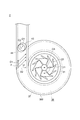
- FIG. 1 It is a schematic diagram which shows schematic structure of the turbocharger which concerns on one Embodiment of this disclosure, and is the schematic diagram which shows the compressor side in the cross section. It is a schematic cross-sectional view which shows the vicinity of the bypass flow path in the turbocharger shown in FIG. It is schematic cross-sectional view which shows the vicinity of the inlet side flow path in the compressor which concerns on one Embodiment of this disclosure. It is schematic cross-sectional view which shows the vicinity of the inlet side flow path in the compressor which concerns on one Embodiment of this disclosure. It is schematic cross-sectional view which shows the vicinity of the inlet side flow path in the compressor which concerns on a comparative example.
- expressions such as “same”, “equal”, and “homogeneous” that indicate that things are in the same state not only represent exactly the same state, but also have tolerances or differences to the extent that the same function can be obtained. It shall also represent the existing state.
- an expression representing a shape such as a quadrangular shape or a cylindrical shape not only represents a shape such as a quadrangular shape or a cylindrical shape in a geometrically strict sense, but also an uneven portion or chamfering within a range in which the same effect can be obtained.
- the shape including the part and the like shall also be represented.
- the expression “includes”, “includes”, or “has” one component is not an exclusive expression that excludes the existence of another component.
- the same reference numerals may be given to the same configurations, and the description thereof may be omitted.
- FIG. 1 is a schematic view schematically showing a configuration of a turbocharger according to an embodiment of the present disclosure, and is a schematic view showing a compressor side in a cross section.
- FIG. 2 is a schematic cross-sectional view showing the vicinity of the bypass flow path in the turbocharger shown in FIG.
- the compressor 2 according to some embodiments is mounted on the turbocharger 1 as shown in FIG.
- the turbocharger 1 comprises a turbocharger for automobiles including a compressor 2 and a turbine 12.
- the compressor 2 includes an impeller 21, a housing (compressor housing) 3 configured to rotatably accommodate the impeller 21, and a bypass valve 5.
- the turbine 12 includes a turbine rotor 13 that is mechanically connected to the impeller 21 via a rotary shaft 11 and a turbine housing 14 that is configured to rotatably accommodate the turbine rotor 13.
- a turbine rotor 13 that is mechanically connected to the impeller 21 via a rotary shaft 11
- a turbine housing 14 that is configured to rotatably accommodate the turbine rotor 13.
- the turbocharger 1 includes a rotary shaft 11, a bearing 15 that rotatably supports the rotary shaft 11, and a bearing housing configured to accommodate the bearing 15. 16 and are further provided.
- the bearing housing 16 is arranged between the housing 3 and the turbine housing 14, and is mechanically connected to the housing 3 and the turbine housing 14 by a fastening member (for example, a fastening bolt or a V clamp).
- the direction in which the axis CA of the impeller 21 (compressor 2) extends is defined as the axial direction X
- the direction orthogonal to the axis CA is defined as the radial direction Y.
- the intake port side left side in the figure
- the side opposite to the intake port 31 side is defined as the rear side XR.
- the rotating shaft 11 has a longitudinal direction along the axial direction X, and the impeller 21 is mechanically connected to one end thereof (the end of the front XF) and to the other end (the end of the rear XR).
- the turbine rotor 13 is mechanically connected.
- the impeller 21 is provided coaxially with the turbine rotor 13.
- "Along a certain direction" includes not only a certain direction but also a direction inclined with respect to a certain direction (for example, within ⁇ 45 ° with respect to a certain direction).
- the housing 3 is formed with an intake port 31 for introducing a gas (for example, a combustion gas such as air) from the outside of the housing 3. Further, the housing 3 is formed with an discharge port (not shown) for discharging the gas that has passed through the impeller 21 to the outside of the housing 3 and sending it to an internal combustion engine (for example, an engine) (not shown).
- a gas for example, a combustion gas such as air
- an internal combustion engine for example, an engine
- the turbocharger 1 rotates the turbine rotor 13 with exhaust gas sent from an internal combustion engine (not shown). Since the impeller 21 is mechanically connected to the turbine rotor 13 via the rotating shaft 11, the impeller 21 rotates integrally in conjunction with the rotation of the turbine rotor 13. By rotating the impeller 21, the turbocharger 1 compresses the gas introduced into the housing 3 and sends it to the internal combustion engine.
- the impeller 21 has a hub 22 and a plurality of impeller blades 23 provided on the outer peripheral surface of the hub 22.
- the hub 22 is mechanically fixed to one end of the rotating shaft 11. Therefore, the hub 22 and the plurality of impeller blades 23 can rotate integrally with the rotating shaft 11 around the axis CA of the impeller 21.
- the impeller 21 is configured to guide the gas sent from the front side XF in the axial direction X to the outside in the radial direction Y.
- a gap (clearance) is formed between the tip 231 (chip side edge) of the impeller blade 23 and the shroud surface 34 of the housing 3.
- the housing 3 has an intake flow path 32 for introducing gas into the impeller 21 from the outside of the housing 3 and a scroll flow path for guiding the gas passing through the impeller 21 to the outside. It has 36 and a bypass flow path 4 that bypasses the impeller 21 and connects the intake flow path 32 and the scroll flow path 36.
- Each of the intake flow path 32, the scroll flow path 36, and the bypass flow path 4 is formed inside the housing 3.
- the housing 3 rotatably accommodates the impeller 21 by being combined with other members (eg, bearing housing 16 and the like), as shown in FIGS. 1 and 2.
- the diffuser flow path 35 that guides the gas from the impeller 21 to the scroll flow path 36 are formed.
- the upstream side in the gas flow direction flowing inside the housing 3 may be simply referred to as the “upstream side”, and the downstream side in the gas flow direction may be simply referred to as the “downstream side”.
- the intake flow path 32 extends along the axial direction X, and extends into the intake port 31 located on the front side XF (upstream side) and the inlet side of the impeller chamber 33 located on the rear side XR (downstream side). Communicating.
- the scroll flow path 36 has a spiral shape that surrounds the circumference of the impeller 21 (outside in the radial direction Y).
- the diffuser flow path 35 extends along a direction intersecting (for example, orthogonal to) the axis CA of the impeller 21 (compressor 2).
- the scroll flow path 36 communicates with the diffuser flow path 35 located on the upstream side and the discharge port (not shown) located on the downstream side.
- the diffuser flow path 35 communicates with the outlet side of the impeller chamber 33 located on the upstream side and the scroll flow path 36.
- the gas is introduced into the inside of the housing 3 from the intake port 31 of the housing 3, flows through the intake flow path 32 to the rear XR along the axial direction X, and then is sent to the impeller 21.
- the gas sent to the impeller 21 flows outward in the radial direction through the diffuser flow path 35 and the scroll flow path 36 in this order, and is then discharged to the outside of the housing 3 from a discharge port (not shown).
- the housing 3 is curved convexly so as to face the intake air introduction portion 320 forming the intake air flow path 32 and the tip end 231 of the impeller blade 23.
- a shroud portion 340 having a shroud surface 34, a scroll flow path forming portion 360 forming the scroll flow path 36, and a bypass flow path forming portion 40 forming the bypass flow path 4 are provided.
- One end of the bypass flow path forming portion 40 is connected to the intake air introducing portion 320, and the other end side is connected to the scroll flow path forming portion 360.
- the intake air introduction unit 320 is formed in a tubular shape having an intake air flow path 32 inside.
- the above-mentioned intake port 31 is formed at the end of the front side XF of the intake intake portion 320.
- the shroud portion 340 is provided between the intake intake introduction portion 320 and the scroll flow path forming portion 360.
- the shroud surface 34 of the shroud portion 340 defines a portion of the front XF of the impeller chamber 33 described above, and faces each of the tips 231 of the impeller blade 23.
- the scroll flow path forming unit 360 has a scroll flow path wall surface 37 that defines the scroll flow path 36.
- the bypass valve 5 has a valve body 51 provided in the bypass flow path 4 and capable of opening and closing the bypass flow path 4.
- the bypass valve 5 further comprises an actuator 52 configured to drive the valve body 51 to control the opening and closing operation of the valve body 51.
- the valve body 51 connects the bypass flow path 4 to the inlet side flow path 41 having a communication port 43 communicating with the scroll flow path 36 and the intake flow path 32 in the fully closed state. It is configured to partition into an outlet side flow path 42 that communicates with the flow path 42.
- the inlet side flow path 41 has an inlet side flow path outlet 44 closed by a valve body 51 on the side opposite to the communication port 43.
- the inlet-side flow path outlet 44 is open to the wall surface 401 (valve seat surface) of the bypass flow path forming portion 40 to which the flat surface 511 abuts when the valve body 51 is fully closed.
- the wall surface 401 defines a part of the outlet side flow path 42.
- the compressor 2 includes the above-mentioned impeller 21, the above-mentioned housing 3, and the above-mentioned bypass valve 5 having a valve body 51.
- the housing 3 has the intake flow path 32, the scroll flow path 36, and the bypass flow path 4 described above.
- the valve body 51 is configured to partition the bypass flow path 4 into the above-mentioned inlet side flow path 41 and the above-mentioned outlet side flow path 42 in the fully closed state.
- the inlet side flow path wall surface 6 for partitioning the inlet side flow path 41 of the housing 3 communicates with each other in a cross-sectional view in which the housing 3 is cut along the axis CA of the impeller 21.
- the upstream side flow path wall surface portion 61 including at least the upstream side flow path wall surface portion 61 connected to the upstream end 45 of the mouth 43 is on the upstream side connected to the upstream end 45 of the scroll flow path wall surface 37 for partitioning the scroll flow path 36.
- the angle ⁇ 1 formed with the scroll wall surface 37A is set to be less than 90 degrees.
- FIG. 5 is a schematic cross-sectional view showing the vicinity of the inlet side flow path in the compressor according to the comparative example.
- the upstream side flow path wall surface portion 61 is formed with the upstream side scroll wall surface 37A in a cross-sectional view in which the housing 3 is cut along the axis CA of the impeller 21.
- the angle ⁇ 1 is configured to exceed 90 degrees.
- the gas flowing along the upstream scroll wall surface 37A in the scroll flow path 36 invades the inlet side flow path 41 along the upstream side flow path wall surface portion 61 and enters the inlet side flow path (41).
- the invading gas flow forms a swirl flow as shown in FIG.
- the gas forms a swirl flow in the inlet side flow path 41, so that the pressure loss region A1 is formed at the central portion of the inlet side flow path 41.
- FIG. 6 is an explanatory diagram for explaining the effect of the compressor according to the embodiment of the present disclosure, and is an explanatory diagram showing the relationship between the intake flow rate (volume flow rate) of the compressor and the efficiency of the compressor.
- the curve C1 in FIG. 6 shows the relationship between the intake flow rate (volumetric flow rate) of the compressor without the bypass flow path 4 and the bypass valve 5 and the efficiency.
- the curve C2 in FIG. 6 shows the relationship between the intake flow rate (volumetric flow rate) and the efficiency of the compressor 2A according to the comparative example. At the maximum output point, the efficiency of the compressor is lower at the point P3 on the curve C2 than at the point P2 on the curve C1. Point P1 in FIG.
- FIG. 6 shows the relationship between the intake flow rate (volumetric flow rate) and the efficiency at the maximum output point of the compressor 2 according to the present embodiment.
- the compressor 2 according to the present embodiment is more efficient than the compressor 2A according to the comparative example at the maximum output point, and is equivalent to the compressor without the bypass flow path 4 and the bypass valve 5. Efficiency has been achieved.
- the upstream side flow path wall surface portion 61 connected to the upstream end 45 of the communication port 43 is configured such that the angle ⁇ 1 formed with the upstream side scroll wall surface 37A connected to the upstream end 45 is less than 90 degrees. Therefore, the gas flowing along the upstream scroll wall surface 37A invades the inlet side flow path 41 as compared with the case where the angle ⁇ 1 formed with the upstream scroll wall surface 37A is 90 degrees or more. Can be suppressed. As a result, it is possible to suppress the flow of gas that has entered the inlet side flow path 41 from forming a swirl flow, so that an increase in pressure loss of the compressor 2 due to the swirl flow formed in the inlet side flow path 41 is suppressed. can do.
- the inlet side flow path wall surface 6 described above is downstream of the communication port 43 in a cross-sectional view of the housing 3 cut along the axis CA of the impeller 21.
- the downstream side flow path wall surface portion 62 further includes the downstream side flow path wall surface portion 62 connected to the end 46, and the downstream side flow path wall surface portion 62 has an angle ⁇ 2 of 90 degrees with the downstream side scroll wall surface 37B connected to the downstream end 46 of the scroll flow path wall surface 37. It was configured to be less than super 180 degrees.
- the downstream flow path wall surface portion 62 connected to the downstream end 46 of the communication port 43 is configured such that the angle ⁇ 2 formed with the downstream scroll wall surface 37B is more than 90 degrees and less than 180 degrees. Therefore, as compared with the case where the angle ⁇ 2 formed with the downstream scroll wall surface 37B is less than 90 degrees, the gas flowing along the upstream scroll wall surface 37A in the scroll flow path 36 invades the inlet side flow path 41. It can be suppressed. As a result, it is possible to suppress the flow of gas that has entered the inlet side flow path 41 from forming a swirl flow, so that an increase in pressure loss of the compressor 2 due to the swirl flow formed in the inlet side flow path 41 is suppressed. can do.
- At least one of the upstream flow path wall surface 61 described above and the downstream flow path wall surface 62 described above has the housing 3 along the axis CA of the impeller 21. In the cut cross-sectional view, it is configured to extend along the extending direction of the tangent line N2 at the downstream end 46 of the communication port 43 of the downstream scroll wall surface 37B.
- each of the upstream side flow path wall surface portion 61 and the downstream side flow path wall surface portion 62 extends along the extending direction of the tangent line N2.
- the tangent line N2 is orthogonal to the straight line connecting the center CB of the scroll flow path 36 and the downstream end 46 at the downstream end 46 in the cross-sectional view.
- the upstream side flow path wall surface portion 61 is linear from the upstream end 45 of the communication port 43 to the upstream end 47 of the inlet side flow path outlet 44.
- the downstream side flow path wall surface portion 62 extends linearly from the downstream end 46 of the communication port 43 to the downstream end 48 of the inlet side flow path outlet 44. Therefore, in the cross-sectional view, the straight line N1 passing through the center O1 of the communication port 43 and the center O2 of the inlet side flow path outlet 44 also extends along the extending direction of the tangent line N2.
- the center O1 of the communication port 43 means the center of gravity of the communication port 43, that is, the center of gravity.
- the center O2 of the inlet-side flow path outlet 44 means the center of gravity of the inlet-side flow path outlet 44, that is, the center of gravity.
- the upstream side flow path wall surface portion 61 and the downstream side flow path wall surface portion 62 extend along the extending direction of the tangent line N2 at the downstream end 46 of the communication port 43 of the downstream side scroll wall surface 37B. Therefore, the inlet side flow path 41 partitioned by the upstream side flow path wall surface portion 61 and the downstream side flow path wall surface portion 62 is defined as the flow direction of the gas flowing through the scroll flow path 36 from the communication port 43. Can be extended in the opposite direction. As a result, it is possible to effectively prevent the gas flowing through the scroll flow path 36 along the upstream scroll wall surface 37A from entering the inlet side flow path 41.
- the area of the surface orthogonal to the straight line N1 described above in the inlet side flow path 41 is the flow path area, in the embodiment shown in FIG. 3, the surface passing through the upstream end 45 of the communication port 43 and the inlet side flow path outlet 44 The flow path area becomes narrower on the surface passing through the downstream end 48.
- At least one of the above-mentioned upstream side flow path wall surface portion 61 and the above-mentioned downstream side flow path wall surface portion 62 (flow path wall surface portions 61, 62). ) Is a curved shape portion (63) that bends concavely in a direction away from the other flow path wall surface portion (flow path wall surface portions 62, 61) in a cross-sectional view obtained by cutting the housing 3 along the axis CA of the impeller 21. , 64).
- the upstream side flow path wall surface portion 61 includes a curved shape portion 63
- the downstream side flow path wall surface portion 62 includes a curved shape portion 64.
- the upstream side flow path wall surface portion 61 and the downstream side flow path wall surface portion 62 are curved in a concave shape in a direction away from the other flow path wall surface portion (flow path wall surface portions 62, 61). Since the shape portion (curve shape portion 63, 64) is included, the opening area of the communication port 43 is suppressed from being increased, and is closed by the valve body 51 rather than the communication port 43 in the middle of the inlet side flow path 41.
- the cross-sectional area (flow path area) at the inlet side flow path outlet 44 (the side where the outlet 44 is located) can be increased.
- the flow rate of the bypass flow path 4 when the valve body 51 is opened can be increased, so that the bypass flow path 4 is required.
- the inlet-side flow path 41 described above extends from the inlet-side flow path outlet 44 closed by the valve body 51 to the communication port 43, and the inlet-side flow path outlet. It was configured so that the flow path area was equal to or larger than the opening area of 44.
- the inlet side flow path 41 extends from the inlet side flow path outlet 44 closed by the valve body 51 to the communication port 43, and has a flow path area equal to or larger than the opening area of the inlet side flow path outlet 44. Therefore, in the open state of the valve body 51, the flow of gas that enters the inlet side flow path 41 of the bypass flow path 4 from the scroll flow path 36 and flows out to the outlet side flow path 42 is not obstructed. , The gas can be passed through the intake flow path 32 as it is. As a result, the flow rate of the bypass flow path 4 when the valve body 51 is opened can be increased.
- FIG. 7 is a schematic view schematically showing a state in which the compressor according to the embodiment of the present disclosure is viewed from the front side in the axial direction.
- the compressor 2 according to some embodiments includes the above-mentioned impeller 21, the above-mentioned housing 3, and the above-mentioned bypass valve 5 having a valve body 51.
- the housing 3 has the intake flow path 32, the scroll flow path 36, and the bypass flow path 4 described above.
- the valve body 51 is configured to partition the bypass flow path 4 into the above-mentioned inlet side flow path 41 and the above-mentioned outlet side flow path 42 in the fully closed state. Then, as shown in FIG.
- the inlet side flow path 41 flows through the scroll flow path 36 as compared with the center O2 of the inlet side flow path outlet 44 in which the center O1 of the communication port 43 is closed by the valve body 51. It is configured to be located on the downstream side in the swirling direction F of the gas.
- the gas flowing through the scroll flow path 36 flows from the upstream side to the downstream side while swirling along the swirling direction F.
- the turning direction F includes a component D1 that moves the scroll flow path 36 from the upstream side to the downstream side and a component D2 that rotates in a direction orthogonal to the component D1, and is inclined (angle) downstream with respect to the component D2. ⁇ ).
- the gas flowing through the scroll flow path 36 flows from the outside in the radial direction in the scroll flow path to the inside in the radial direction along the wall surface located on the front side in the drawing.
- the center O1 of the communication port 43 is located downstream of the center O2 of the inlet side flow path outlet 44 in the swirling direction F of the gas flowing through the scroll flow path 36. It is configured to do.
- the inlet side flow path 41 extends in the direction opposite to the swirling direction F of the gas flowing in the scroll flow path 36, the gas flowing in the scroll flow path 36 along the swirling direction F flows. , It is possible to suppress the invasion into the inlet side flow path 41. As a result, it is possible to suppress the flow of gas that has entered the inlet side flow path 41 from forming a swirl flow, so that an increase in pressure loss of the compressor 2 due to the swirl flow formed in the inlet side flow path 41 is suppressed. can do.
- this embodiment can be implemented independently, it may be combined with some of the above-described embodiments. By combining this embodiment with some of the above-described embodiments, it is possible to more effectively suppress the gas flowing through the scroll flow path 36 from entering the inlet side flow path 41.
- the compressor 2 includes the above-mentioned compressor 2 having an impeller 21 and a housing 3, and a turbine rotor 13 connected to the impeller 21 of the compressor 2 via a rotary shaft 11.
- a turbine 12 having a In this case, the increase in pressure loss of the compressor 2 due to the swirl flow formed in the inlet side flow path 41 can be suppressed, so that the efficiency of the compressor 2 can be improved.
- the present disclosure is not limited to the above-described embodiment, and includes a modified form of the above-described embodiment and a combination of these embodiments as appropriate.
- the compressor (2) according to at least one embodiment of the present disclosure is Impeller (21) and A housing (3) configured to rotatably house the impeller (21).
- An intake flow path (32) for introducing a gas into the impeller (21) from the outside of the housing (3),
- the scroll flow path (36) for guiding the gas that has passed through the impeller (21) to the outside, and the intake flow path (32) and the scroll flow path (36) bypassing the impeller (21).
- the valve body (51) has an inlet side flow path (41) having a communication port (43) that communicates the bypass flow path (4) with the scroll flow path (36) in a fully closed state, and the intake flow. It is configured to partition into an outlet side flow path (42) communicating with the road (32).
- the inlet-side flow path wall surface (6) that partitions the inlet-side flow path (41) has the communication port (6) in a cross-sectional view in which the housing (3) is cut along the axis (CA) of the impeller (21). At least the upstream side flow path wall surface portion (61) connected to the upstream end (45) of 43) is included.
- the upstream side flow path wall surface portion (61) forms with the upstream side scroll wall surface (37A) connected to the upstream end (45) of the scroll flow path wall surface (37) that partitions the scroll flow path (36).
- the angle ( ⁇ 1) was configured to be less than 90 degrees.
- the upstream side flow path wall surface portion (61) connected to the upstream end (45) of the communication port (43) is connected to the upstream side scroll wall surface (37A) connected to the upstream end (45). Since the angle ( ⁇ 1) formed is less than 90 degrees, the scroll flow path (36) can be set as compared with the case where the angle ( ⁇ 1) formed with the upstream scroll wall surface (37A) is 90 degrees or more. It is possible to prevent the gas flowing along the upstream scroll wall surface (37A) from entering the inlet side flow path (41).
- the compressor (2) does not have to have the surface (511) of the valve body (51) of the bypass valve (5) along the scroll flow path wall surface (37) as in the configuration described in Patent Document 1. ) Can suppress the increase in pressure loss. Therefore, it is possible to suppress the increase in the pressure loss of the compressor (2) while suppressing the increase in cost by suppressing the complication of the shape of the valve body (51) of the bypass valve (5).
- the compressor (2) described in 1) above is The inlet side flow path wall surface (41) is connected to the downstream end (46) of the communication port (43) in a cross-sectional view of the housing (3) cut along the axis (CA) of the impeller (21). Further including the downstream side flow path wall surface portion (62), The angle ( ⁇ 2) formed by the downstream side flow path wall surface portion (62) with the downstream side scroll wall surface (37B) connected to the downstream end (46) of the scroll flow path wall surface (37) is more than 90 degrees 180. It was configured to be less than a right angle.
- the downstream side flow path wall surface portion (62) connected to the downstream end (46) of the communication port (43) has an angle ( ⁇ 2) of 90 degrees with the downstream side scroll wall surface (37B). Since it is configured to be less than 180 degrees, the scroll flow path (36) can be moved to the upstream scroll wall surface as compared with the case where the angle ( ⁇ 2) with the downstream scroll wall surface (37B) is less than 90 degrees. It is possible to prevent the gas flowing along (37A) from entering the inlet side flow path (41).
- At least one of the upstream side flow path wall surface portion (61) and the downstream side flow path wall surface portion (62) is in a cross-sectional view in which the housing (3) is cut along the axis (CA) of the impeller (21).
- the downstream side scroll wall surface (37B) is configured to extend along the extending direction of the tangent line (N2) at the downstream end (46) of the communication port (43).
- the upstream side flow path wall surface portion (61) and the downstream side flow path wall surface portion (62) are at the downstream end (46) of the communication port (43) of the downstream side scroll wall surface (37B). Since it is configured to extend along the extending direction of the tangent line (N2), the inlet side flow path is partitioned by the upstream side flow path wall surface portion (61) and the downstream side flow path wall surface portion (62). (41) can be extended in the direction opposite to the flow direction of the gas flowing through the scroll flow path (36) from the communication port (43). As a result, it is possible to effectively prevent the gas flowing along the scroll flow path (36) along the upstream scroll wall surface (37A) from entering the inlet flow path (41).
- the compressor (2) according to 2) above. At least one of the upstream side flow path wall surface portion (61) and the downstream side flow path wall surface portion (62) has the housing (3) attached to the axis (2) of the impeller (2). In the cross-sectional view cut along the CA), the curved portion (63, 64) that bends concavely in the direction away from the other flow path wall surface portion (62, 61) is included.
- the upstream side flow path wall surface portion (61) and the downstream side flow path wall surface portion (62) are concave in the direction away from the other flow path wall surface portion (62, 61). Since it includes curved curved portions (63, 64), it suppresses an increase in the opening area of the communication port (43), and is in the middle of the inlet side flow path (41) (by the valve body 51 rather than the communication port 43).
- the cross-sectional area on the side where the inlet side flow path outlet 44 to be closed is located) can be increased.
- the flow rate of the bypass flow path (4) when the valve body (51) is opened can be increased, so that the required bypass flow path can be increased.
- the flow rate of (4) can be secured.
- the inlet side flow path (41) extends from the inlet side flow path outlet (44) closed by the valve body (51) to the communication port (43), and is an opening of the inlet side flow path outlet (44). It was configured so that the flow path area was larger than the area.
- the inlet side flow path (41) extends from the inlet side flow path outlet (44) closed by the valve body (51) to the communication port (43), and the inlet side flow path outlet. Since the flow path area is larger than the opening area of (44), the flow path on the inlet side (4) from the scroll flow path (36) to the bypass flow path (4) in the open state of the valve body (51). The gas can flow directly into the intake flow path (32) without obstructing the flow of the gas that enters the 41) and flows out into the outlet side flow path (42). As a result, the flow rate of the bypass flow path (4) when the valve body (51) is opened can be increased.
- the compressor (2) according to any one of 1) to 5) above.
- the inlet side flow path (41) is said to have a center (O2) of the communication port (43) as compared with a center (O2) of the inlet side flow path outlet (44) whose communication port (43) is closed by the valve body (51). It is configured to be located on the downstream side in the swirling direction (F) of the gas flowing through the scroll flow path (36).
- the center (O1) of the communication port (43) is the scroll flow path (O2) as compared with the center (O2) of the inlet side flow path outlet (44). It is configured to be located on the downstream side in the swirling direction (F) of the gas flowing in 36).
- the inlet side flow path (41) extends in the direction opposite to the swirling direction (F) of the gas flowing through the scroll flow path (36), it swirls in the scroll flow path (36). It is possible to prevent the gas flowing along the direction (F) from entering the inlet side flow path (41).
- the compressor (2) is Impeller (21) and A housing (3) configured to rotatably house the impeller (21).
- the valve body (51) has an inlet side flow path (41) having a communication port (43) that communicates the bypass flow path (4) with the scroll flow path (36) in a fully closed state, and the intake flow. It is configured to partition into an outlet side flow path (42) communicating with the road (32).
- the inlet side flow path (41) is said to have a center (O2) of the communication port (43) as compared with a center (O2) of the inlet side flow path outlet (44) whose communication port (43) is closed by the valve body (51). It is configured to be located on the downstream side in the swirling direction (F) of the gas flowing through the scroll flow path (36).
- the center (O1) of the communication port (43) is the scroll flow path (O2) as compared with the center (O2) of the inlet side flow path outlet (44). It is configured to be located on the downstream side in the swirling direction (F) of the gas flowing in 36).
- the inlet side flow path (41) extends in the direction opposite to the swirling direction (F) of the gas flowing through the scroll flow path (36), it swirls in the scroll flow path (36). It is possible to prevent the gas flowing along the direction (F) from entering the inlet side flow path (41).
- the compressor (2) does not have to have the surface (511) of the valve body (51) of the bypass valve (5) along the scroll flow path wall surface (37) as in the configuration described in Patent Document 1. ) Can suppress the increase in pressure loss. Therefore, it is possible to suppress the increase in the pressure loss of the compressor (2) while suppressing the increase in cost by suppressing the complication of the shape of the valve body (51) of the bypass valve (5).
- the turbocharger (1) is The compressor (2) according to any one of 1) to 7) above, and A turbine (12) having a turbine rotor (13) connected to the impeller (21) of the compressor (2) via a rotating shaft (11) is provided.
Abstract
コンプレッサは、インペラと、インペラを回転可能に収容するハウジングであって、外部からインペラに気体を導入するための吸気流路、インペラを通過した気体を外部へ導くためのスクロール流路、インペラを迂回して吸気流路とスクロール流路とを接続するバイパス流路、を有するハウジングと、バイパス流路を開閉可能な弁体を有するバイパスバルブと、を備え、弁体は、全閉状態においてバイパス流路を、スクロール流路に連通する連通口を有する入口側流路と、吸気流路に連通する出口側流路と、に仕切るように構成され、入口側流路を区画する入口側流路壁面は、ハウジングをインペラの軸線に沿って切断した断面視において、連通口の上流端に連なる上流側流路壁面部を少なくとも含み、上流側流路壁面部は、スクロール流路を区画するスクロール流路壁面のうちの上流端に連なる上流側スクロール壁面とのなす角度が90度未満となるように構成された。
Description
本開示は、コンプレッサおよび該コンプレッサを備えるターボチャージャに関する。
例えば、乗用車用のターボチャージャの遠心コンプレッサは、低速状態のエンジンの急加速時に、小流量側の作動限界であるサージングライン近傍で運転される。一般に遠心コンプレッサは、サージングラインに対して所定のマージンを確保したうえで運転されるが、サージングを動的に回避するためのフェイルセーフデバイスとしてバイパスバルブが用いられることがある。
バイパスバルブは、コンプレッサの出口側(インペラよりも下流側のスクロール流路)と入口側(インペラよりも上流側の供給流路)とを繋ぐバイパス流路を開閉する機能を有する。エンジンの平常作動時には、バイパスバルブがバイパス流路を閉じている。例えばタービンの過回転による過給圧の急上昇などのような、サージマージンの急激な減少を伴う外乱が生じた場合には、バイパスバルブがバイパス流路を開き、コンプレッサの出口側を流れる圧縮流体を、バイパス流路を介してコンプレッサの入口側に還流させ、コンプレッサの過給圧を低下させることで、サージマージンを確保している。
一方、このようなバイパス流路を設けることは圧力損失の増加にも繋がる。具体的には、バイパスバルブがバイパス流路を閉じた状態において、バイパス流路には、スクロール流路に連通するキャビティ部が形成される。該キャビティ部にスクロール流路を流れる流体が大量に流入するような構成であると、キャビティ部に流入した流れがスワールを形成した後に、再びスクロール流路に戻ろうとした際に、スクロール流路を流れる流体に干渉して大きな圧力損失を生じさせ、コンプレッサの効率を低下させる虞がある。例えば、バイパス流路やバイパスバルブを設ける上記コンプレッサは、バイパス流路やバイパスバルブを設けない構成に比べて、エンジンの最大出力点における効率が2~3%程度低下することがある。この効率低下量は、コンプレッサ全体における損失の概略10%に相当する。
このような圧力損失増加の問題に対し、特許文献1では、バイパスバルブの弁体の表面をコンプレッサのスクロール流路の内壁に沿った形状に形成することを提案している。このような構造にすればバイパス流路への流れの流入による圧力損失の増大を抑制することができる。
しかしながら、バイパスバルブは汎用品が採用されることが多く、弁体の表面を配管の内壁に沿った特殊な形状にするには特注品を用いる必要があり、コストの増加を招いてしまう。
上述した事情に鑑みて、本開示の少なくとも一実施形態の目的は、バイパスバルブの弁体の形状の複雑化を抑制しつつコンプレッサの圧力損失の増大を抑制することができるコンプレッサ、および該コンプレッサを備えるターボチャージャを提供することにある。
本開示にかかるコンプレッサは、
インペラと、
前記インペラを回転可能に収容するように構成されたハウジングであって、
前記ハウジングの外部から前記インペラに気体を導入するための吸気流路、
前記インペラを通過した前記気体を外部へ導くためのスクロール流路、および
前記インペラを迂回して前記吸気流路と前記スクロール流路とを接続するバイパス流路、を有するハウジングと、
前記バイパス流路に設けられて前記バイパス流路を開閉可能な弁体を有するバイパスバルブと、を備え、
前記弁体は、全閉状態において前記バイパス流路を、前記スクロール流路に連通する連通口を有する入口側流路と、前記吸気流路に連通する出口側流路と、に仕切るように構成され、
前記入口側流路を区画する入口側流路壁面は、前記ハウジングを前記インペラの軸線に沿って切断した断面視において、前記連通口の上流端に連なる上流側流路壁面部を少なくとも含み、
前記上流側流路壁面部は、前記スクロール流路を区画するスクロール流路壁面のうちの前記上流端に連なる上流側スクロール壁面とのなす角度が90度未満となるように構成された。
本開示にかかるターボチャージャは、
前記コンプレッサと、
前記コンプレッサの前記インペラに回転シャフトを介して連結されるタービンロータを有するタービンと、を備える。
前記コンプレッサと、
前記コンプレッサの前記インペラに回転シャフトを介して連結されるタービンロータを有するタービンと、を備える。
本開示の少なくとも一実施形態によれば、バイパスバルブの弁体の形状の複雑化を抑制しつつコンプレッサの圧力損失の増大を抑制することができるコンプレッサ、および該コンプレッサを備えるターボチャージャが提供される。
以下、添付図面を参照して本開示の幾つかの実施形態について説明する。ただし、実施形態として記載されている又は図面に示されている構成部品の寸法、材質、形状、その相対的配置等は、本開示の範囲をこれに限定する趣旨ではなく、単なる説明例にすぎない。
例えば、「ある方向に」、「ある方向に沿って」、「平行」、「直交」、「中心」、「同心」或いは「同軸」等の相対的或いは絶対的な配置を表す表現は、厳密にそのような配置を表すのみならず、公差、若しくは、同じ機能が得られる程度の角度や距離をもって相対的に変位している状態も表すものとする。
例えば、「同一」、「等しい」及び「均質」等の物事が等しい状態であることを表す表現は、厳密に等しい状態を表すのみならず、公差、若しくは、同じ機能が得られる程度の差が存在している状態も表すものとする。
例えば、四角形状や円筒形状等の形状を表す表現は、幾何学的に厳密な意味での四角形状や円筒形状等の形状を表すのみならず、同じ効果が得られる範囲で、凹凸部や面取り部等を含む形状も表すものとする。
一方、一の構成要素を「備える」、「含む」、又は、「有する」という表現は、他の構成要素の存在を除外する排他的な表現ではない。
なお、同様の構成については同じ符号を付し説明を省略することがある。
(ターボチャージャ)
図1は、本開示の一実施形態にかかるターボチャージャの構成を概略的に示す概略図であって、コンプレッサ側を断面で示す概略図である。図2は、図1に示すターボチャージャにおけるバイパス流路近傍を示す概略断面図である。
幾つかの実施形態にかかるコンプレッサ2は、図1に示されるように、ターボチャージャ1に搭載される。ターボチャージャ1は、コンプレッサ2とタービン12とを備える自動車用のターボチャージャからなる。コンプレッサ2は、インペラ21と、インペラ21を回転可能に収容するように構成されたハウジング(コンプレッサハウジング)3と、バイパスバルブ5と、を備える。タービン12は、インペラ21に回転シャフト11を介して機械的に連結されるタービンロータ13と、タービンロータ13を回転可能に収容するように構成されたタービンハウジング14と、を備える。なお、ターボチャージャとして自動車用のターボチャージャ1を例に挙げて説明するが、本開示は、自動車以外の用途(例えば、船舶や陸上発電)に用いられるターボチャージャにも適用可能である。
図示される実施形態では、ターボチャージャ1は、図1に示されるように、回転シャフト11と、回転シャフト11を回転可能に支持する軸受15と、軸受15を収容するように構成された軸受ハウジング16と、をさらに備える。軸受ハウジング16は、ハウジング3とタービンハウジング14との間に配置され、締結部材(例えば、締結ボルトやVクランプなど)により、ハウジング3やタービンハウジング14に機械的に連結されている。
以下、例えば図1に示されるように、インペラ21(コンプレッサ2)の軸線CAが延在する方向を軸方向Xとし、軸線CAに直交する方向を径方向Yとする。軸方向Xのうち、インペラ21に対して吸気口31が位置する吸気口側(図中左側)を前側XFとし、吸気口31側と反対側(図中右側)を後側XRと定義する。
回転シャフト11は、軸方向Xに沿って長手方向を有し、その一端部(前側XFの端部)にインペラ21が機械的に連結され、その他端部に(後側XRの端部)にタービンロータ13が機械的に連結されている。図示される実施形態では、インペラ21は、タービンロータ13と同軸上に設けられている。「或る方向に沿って」とは、或る方向だけでなく、或る方向に対して傾斜する方向(例えば、或る方向に対して±45°以内)をも含む。
ハウジング3には、図1に示されるように、ハウジング3の外部から気体(例えば、空気などの燃焼用気体)を導入するための吸気口31が形成されている。また、ハウジング3には、インペラ21を通過した気体をハウジング3の外部に排出して不図示の内燃機関(例えば、エンジン)に送るための不図示の排出口が形成されている。
ターボチャージャ1は、不図示の内燃機関から送られた排ガスにより、タービンロータ13を回転させる。インペラ21は、回転シャフト11を介してタービンロータ13に機械的に連結されているので、タービンロータ13の回転に連動して一体的に回転する。ターボチャージャ1は、インペラ21を回転させることにより、ハウジング3の内部に導入された気体を圧縮して上記内燃機関に送る。
(インペラ)
インペラ21は、図1に示されるように、ハブ22およびハブ22の外周面に設けられた複数のインペラ翼23を有する。ハブ22は、回転シャフト11の一端部に機械的に固定されている。このため、ハブ22や複数のインペラ翼23は、インペラ21の軸線CAを中心として回転シャフト11と一体的に回転可能である。インペラ21は、軸方向Xの前側XFから送られる気体を径方向Yにおける外側に導くように構成されている。インペラ翼23の先端231(チップ側縁)は、ハウジング3のシュラウド面34との間に隙間(クリアランス)が形成されている。
インペラ21は、図1に示されるように、ハブ22およびハブ22の外周面に設けられた複数のインペラ翼23を有する。ハブ22は、回転シャフト11の一端部に機械的に固定されている。このため、ハブ22や複数のインペラ翼23は、インペラ21の軸線CAを中心として回転シャフト11と一体的に回転可能である。インペラ21は、軸方向Xの前側XFから送られる気体を径方向Yにおける外側に導くように構成されている。インペラ翼23の先端231(チップ側縁)は、ハウジング3のシュラウド面34との間に隙間(クリアランス)が形成されている。
(ハウジングの基本的構成)
ハウジング3は、図1、図2に示されるように、ハウジング3の外部からインペラ21に気体を導入するための吸気流路32と、インペラ21を通過した気体を外部へ導くためのスクロール流路36と、インペラ21を迂回して吸気流路32とスクロール流路36とを接続するバイパス流路4と、を有する。吸気流路32、スクロール流路36およびバイパス流路4の夫々は、ハウジング3の内部に形成されている。
ハウジング3は、図1、図2に示されるように、ハウジング3の外部からインペラ21に気体を導入するための吸気流路32と、インペラ21を通過した気体を外部へ導くためのスクロール流路36と、インペラ21を迂回して吸気流路32とスクロール流路36とを接続するバイパス流路4と、を有する。吸気流路32、スクロール流路36およびバイパス流路4の夫々は、ハウジング3の内部に形成されている。
図示される実施形態では、ハウジング3は、図1、図2に示されるように、他の部材(例えば、軸受ハウジング16など)と組み合わされることで、インペラ21を回転可能に収容するインペラ室33と、インペラ21からの気体をスクロール流路36に導くディフューザ流路35と、が形成されるように構成されている。以下、ハウジング3の内部を流れる気体の流れ方向における上流側を単に「上流側」、気体の流れ方向における下流側を単に「下流側」と言うことがある。
吸気流路32は、軸方向Xに沿って延在し、その前側XF(上流側)に位置する吸気口31と、その後側XR(下流側)に位置するインペラ室33の入口側と、に連通している。スクロール流路36は、インペラ21の周囲(径方向Yにおける外側)を囲むような渦巻き形状を有する。ディフューザ流路35は、インペラ21(コンプレッサ2)の軸線CAに交差(例えば、直交)する方向に沿って延在している。スクロール流路36は、上流側に位置するディフューザ流路35と、下流側に位置する不図示の排出口と、に連通している。ディフューザ流路35は、上流側に位置するインペラ室33の出口側と、スクロール流路36に連通している。
気体は、ハウジング3の吸気口31からハウジング3の内部に導入され、吸気流路32を軸方向Xに沿って後側XRに流れた後に、インペラ21に送られる。インペラ21に送られた気体は、径方向における外側に向かいディフューザ流路35およびスクロール流路36をこの順に流れた後に、不図示の排出口からハウジング3の外部に排出される。
図示される実施形態では、ハウジング3は、図1、図2に示されるように、吸気流路32を形成する吸気導入部320と、インペラ翼23の先端231に対向するように凸状に湾曲するシュラウド面34を有するシュラウド部340と、スクロール流路36を形成するスクロール流路形成部360と、バイパス流路4を形成するバイパス流路形成部40と、を備える。バイパス流路形成部40は、その一端側が吸気導入部320に接続され、その他端側がスクロール流路形成部360に接続されている。
吸気導入部320は、吸気流路32を内部に有する筒状に形成されている。吸気導入部320の前側XFの端部には、上述した吸気口31が形成されている。
シュラウド部340は、吸気導入部320とスクロール流路形成部360の間に設けられる。シュラウド部340のシュラウド面34は、上述したインペラ室33の前側XFの部分を画定しており、インペラ翼23の先端231の夫々に対向している。
スクロール流路形成部360は、スクロール流路36を画定するスクロール流路壁面37を有する。
シュラウド部340は、吸気導入部320とスクロール流路形成部360の間に設けられる。シュラウド部340のシュラウド面34は、上述したインペラ室33の前側XFの部分を画定しており、インペラ翼23の先端231の夫々に対向している。
スクロール流路形成部360は、スクロール流路36を画定するスクロール流路壁面37を有する。
(バイパスバルブ)
バイパスバルブ5は、図1、図2に示されるように、バイパス流路4に設けられてバイパス流路4を開閉可能な弁体51を有する。図示される実施形態では、バイパスバルブ5は、弁体51を駆動して弁体51の開閉動作を制御するように構成されたアクチュエータ52をさらに有する。コンプレッサ2の吐出圧が過度に上昇した場合にバイパス流路4を開く開状態となり、スクロール流路36を流れる気体(インペラ21により圧縮された気体)を、バイパス流路4を介して吸気流路32に還流させる。コンプレッサ2の吐出圧が低い場合には、バイパス流路4を弁体51により閉じる閉状態となる。
バイパスバルブ5は、図1、図2に示されるように、バイパス流路4に設けられてバイパス流路4を開閉可能な弁体51を有する。図示される実施形態では、バイパスバルブ5は、弁体51を駆動して弁体51の開閉動作を制御するように構成されたアクチュエータ52をさらに有する。コンプレッサ2の吐出圧が過度に上昇した場合にバイパス流路4を開く開状態となり、スクロール流路36を流れる気体(インペラ21により圧縮された気体)を、バイパス流路4を介して吸気流路32に還流させる。コンプレッサ2の吐出圧が低い場合には、バイパス流路4を弁体51により閉じる閉状態となる。
弁体51は、図1、図2に示されるように、全閉状態においてバイパス流路4を、スクロール流路36に連通する連通口43を有する入口側流路41と、吸気流路32に連通する出口側流路42と、に仕切るように構成されている。入口側流路41は、連通口43とは反対側に弁体51により閉止される入口側流路出口44を有する。入口側流路出口44は、弁体51が全閉状態においてその平坦な表面511が当接するバイパス流路形成部40の壁面401(弁座面)に開口している。この壁面401は、出口側流路42の一部を画定している。弁体51が開状態になると、弁体51の表面511が壁面401から離隔して、入口側流路出口44を介して、入口側流路41と出口側流路42とが連通する。
図3及び図4の夫々は、本開示の一実施形態にかかるコンプレッサにおける入口側流路近傍を示す概略断面図である。図3、図4及び後述する図5におけるスクロール流路36内の矢印は、気体の流れを示すものである。
幾つかの実施形態にかかるコンプレッサ2は、図1、2に示されるように、上述したインペラ21と、上述したハウジング3と、上述した弁体51を有するバイパスバルブ5と、を備える。ハウジング3は、上述した吸気流路32、スクロール流路36およびバイパス流路4を有する。弁体51は、全閉状態においてバイパス流路4を、上述した入口側流路41と上述した出口側流路42とに仕切るように構成されている。そして、図3、図4に示されるように、ハウジング3の入口側流路41を区画する入口側流路壁面6は、ハウジング3をインペラ21の軸線CAに沿って切断した断面視において、連通口43の上流端45に連なる上流側流路壁面部61を少なくとも含み、上流側流路壁面部61は、スクロール流路36を区画するスクロール流路壁面37のうちの上流端45に連なる上流側スクロール壁面37Aとのなす角度θ1が90度未満となるように構成された。
幾つかの実施形態にかかるコンプレッサ2は、図1、2に示されるように、上述したインペラ21と、上述したハウジング3と、上述した弁体51を有するバイパスバルブ5と、を備える。ハウジング3は、上述した吸気流路32、スクロール流路36およびバイパス流路4を有する。弁体51は、全閉状態においてバイパス流路4を、上述した入口側流路41と上述した出口側流路42とに仕切るように構成されている。そして、図3、図4に示されるように、ハウジング3の入口側流路41を区画する入口側流路壁面6は、ハウジング3をインペラ21の軸線CAに沿って切断した断面視において、連通口43の上流端45に連なる上流側流路壁面部61を少なくとも含み、上流側流路壁面部61は、スクロール流路36を区画するスクロール流路壁面37のうちの上流端45に連なる上流側スクロール壁面37Aとのなす角度θ1が90度未満となるように構成された。
図5は、比較例にかかるコンプレッサにおける入口側流路近傍を示す概略断面図である。比較例にかかるコンプレッサ2Aは、図5に示されるように、ハウジング3をインペラ21の軸線CAに沿って切断した断面視において、上流側流路壁面部61は、上流側スクロール壁面37Aとのなす角度θ1が90度超となるように構成されている。この場合には、スクロール流路36を上流側スクロール壁面37Aに沿って流れる気体が、上流側流路壁面部61に沿って入口側流路41に侵入し、この入口側流路(41)に侵入した気体の流れが図5に示されるようなスワール流れを形成する。気体が入口側流路41においてスワール流れを形成することで、入口側流路41の中心箇所に圧力損失領域A1が形成される。
図6は、本開示の一実施形態にかかるコンプレッサの効果を説明するための説明図であって、コンプレッサの吸気流量(体積流量)とコンプレッサの効率との関係を示す説明図である。図6における曲線C1は、バイパス流路4やバイパスバルブ5を備えないコンプレッサの吸気流量(体積流量)と効率との関係を示している。図6における曲線C2は、比較例にかかるコンプレッサ2Aの吸気流量(体積流量)と効率との関係を示している。最大出力点においては、曲線C1上の点P2に比べて、曲線C2上の点P3は、コンプレッサの効率が低下している。図6における点P1は、本実施形態にかかるコンプレッサ2の最大出力点における吸気流量(体積流量)と効率との関係を示すものである。図6に示されるように、本実施形態にかかるコンプレッサ2は、最大出力点において、比較例にかかるコンプレッサ2Aに比べて効率が良く、バイパス流路4やバイパスバルブ5を備えないコンプレッサと同等の効率が達成されている。
上記の構成によれば、連通口43の上流端45に連なる上流側流路壁面部61は、該上流端45に連なる上流側スクロール壁面37Aとのなす角度θ1が90度未満となるように構成されているので、上流側スクロール壁面37Aとのなす角度θ1が90度以上の場合に比べて、スクロール流路36を上流側スクロール壁面37Aに沿って流れる気体が、入口側流路41に侵入することを抑制することができる。これにより、入口側流路41に侵入した気体の流れがスワール流れを形成することを抑制することができるため、入口側流路41に形成されるスワール流れによるコンプレッサ2の圧力損失の増大を抑制することができる。
また、特許文献1に記載された構成のように、バイパスバルブ5の弁体51の表面511をスクロール流路壁面37に沿った形状にしなくても、コンプレッサ2の圧力損失の増大を抑制することができる。したがって、バイパスバルブ5の弁体51の形状の複雑化を抑制してコストの増加を抑制しつつ、コンプレッサ2の圧力損失の増大を抑制することができる。
また、特許文献1に記載された構成では、バイパスバルブ5の弁体51をスクロール流路壁面37に沿って設けるためには、弁体51の設置スペースや可動スペースをバイパス流路4におけるスクロール流路36に近接する位置に設けることが必要となるので、コンプレッサ2の吸気流路32に接続する必要があるバイパス流路4のレイアウトに制約が生じやすい。これに対して、上記の構成によれば、バイパスバルブ5の弁体51をスクロール流路壁面37に沿って設けなくとも圧力損失の増大を抑制できるため、弁体51の設置スペースや可動スペースをバイパス流路4におけるスクロール流路36に近接する位置に設ける必要がなく、コンプレッサ2の吸気流路32に接続するバイパス流路4のレイアウトの自由度を高めることができる。
幾つかの実施形態では、図3、図4に示されるように、上述した入口側流路壁面6は、ハウジング3をインペラ21の軸線CAに沿って切断した断面視において、連通口43の下流端46に連なる下流側流路壁面部62をさらに含み、下流側流路壁面部62は、スクロール流路壁面37のうちの下流端46に連なる下流側スクロール壁面37Bとのなす角度θ2が90度超180度未満となるように構成された。
上記の構成によれば、連通口43の下流端46に連なる下流側流路壁面部62は、下流側スクロール壁面37Bとのなす角度θ2が90度超180度未満となるように構成されているので、下流側スクロール壁面37Bとのなす角度θ2が90度未満である場合に比べて、スクロール流路36を上流側スクロール壁面37Aに沿って流れる気体が、入口側流路41に侵入することを抑制することができる。これにより、入口側流路41に侵入した気体の流れがスワール流れを形成することを抑制することができるため、入口側流路41に形成されるスワール流れによるコンプレッサ2の圧力損失の増大を抑制することができる。
幾つかの実施形態では、図3に示されるように、上述した上流側流路壁面部61および上述した下流側流路壁面部62の少なくとも一方は、ハウジング3をインペラ21の軸線CAに沿って切断した断面視において、下流側スクロール壁面37Bの連通口43の下流端46における接線N2の延在する方向に沿って延在するように構成された。図示に示される実施形態では、図3に示されるような断面視において、上流側流路壁面部61および下流側流路壁面部62の夫々が接線N2の延在する方向に沿って延在している。ここで、接線N2は、上記断面視において、スクロール流路36の中心CBと下流端46とを繋ぐ直線に対して、下流端46において直交している。
図示される実施形態では、図3に示されるような断面視において、上流側流路壁面部61は、連通口43の上流端45から入口側流路出口44の上流端47までに亘り直線状に延在しており、下流側流路壁面部62は、連通口43の下流端46から入口側流路出口44の下流端48までに亘り直線状に延在している。このため、上記断面視において、連通口43の中心O1と入口側流路出口44の中心O2とを通る直線N1もまた、接線N2の延在する方向に沿って延在している。ここで、連通口43の中心O1は、連通口43の図心すなわち重心を意味している。入口側流路出口44の中心O2は、入口側流路出口44の図心すなわち重心を意味している。
上記の構成によれば、上流側流路壁面部61や下流側流路壁面部62が、下流側スクロール壁面37Bの連通口43の下流端46における接線N2の延在する方向に沿って延在するように構成されているので、上流側流路壁面部61や下流側流路壁面部62により区画される入口側流路41を、連通口43からスクロール流路36を流れる気体の流れ方向とは逆方向に向かって延在させることができる。これにより、スクロール流路36を上流側スクロール壁面37Aに沿って流れる気体が、入口側流路41に侵入することを効果的に抑制することができる。
入口側流路41における上述した直線N1に直交する面の面積を流路面積とすると、図3に示される実施形態では、連通口43の上流端45を通る面や入口側流路出口44の下流端48を通る面において流路面積が狭くなる。
幾つかの実施形態では、図4に示されるように、上述した上流側流路壁面部61および上述した下流側流路壁面部62の少なくとも一方の流路壁面部(流路壁面部61、62)は、ハウジング3をインペラ21の軸線CAに沿って切断した断面視において、他方の流路壁面部(流路壁面部62、61)から離隔する方向に向かって凹状に曲がる曲線形状部(63、64)を含む。図4に示される実施形態では、上記断面視において、上流側流路壁面部61は、曲線形状部63を含み、下流側流路壁面部62は、曲線形状部64を含む。これにより、図3に示される実施形態に比べて、連通口43の上流端45を通る面や入口側流路出口44の下流端48を通る面において流路面積が拡大している。
上記の構成によれば、上流側流路壁面部61や下流側流路壁面部62が、他方の流路壁面部(流路壁面部62、61)から離隔する方向に向かって凹状に曲がる曲線形状部(曲線形状部63、64)を含んでいるので、連通口43の開口面積の増大化を抑制しつつ、入口側流路41の途中(連通口43よりも弁体51により閉止される入口側流路出口44が位置する側)における断面積(流路面積)を大きくすることができる。入口側流路41の途中の断面積(流路面積)を大きくすることで、弁体51を開いた際のバイパス流路4の流量を増加させることができるため、必要とするバイパス流路4の流量を確保することができる。
幾つかの実施形態では、図4に示されるように、上述した入口側流路41は、弁体51により閉止される入口側流路出口44から連通口43までに亘り、入口側流路出口44の開口面積以上の流路面積となるように構成された。
上記の構成によれば、入口側流路41は、弁体51により閉止される入口側流路出口44から連通口43までに亘り、入口側流路出口44の開口面積以上の流路面積となるように構成されているので、弁体51の開状態において、スクロール流路36からバイパス流路4の入口側流路41に入り込み、出口側流路42に流れ出す気体の流れを阻害せずに、上記気体をそのまま吸気流路32に流すことができる。これにより、弁体51を開いた際のバイパス流路4の流量を増加させることができる。
図7は、本開示の一実施形態にかかるコンプレッサを軸方向における前側から視た状態を概略的に示す概略図である。
幾つかの実施形態にかかるコンプレッサ2は、図1、2に示されるように、上述したインペラ21と、上述したハウジング3と、上述した弁体51を有するバイパスバルブ5と、を備える。ハウジング3は、上述した吸気流路32、スクロール流路36およびバイパス流路4を有する。弁体51は、全閉状態においてバイパス流路4を、上述した入口側流路41と上述した出口側流路42とに仕切るように構成されている。そして、図7に示されるように、入口側流路41は、連通口43の中心O1が弁体51により閉止される入口側流路出口44の中心O2に比べて、スクロール流路36を流れる気体の旋回方向Fにおける下流側に位置するように構成された。
幾つかの実施形態にかかるコンプレッサ2は、図1、2に示されるように、上述したインペラ21と、上述したハウジング3と、上述した弁体51を有するバイパスバルブ5と、を備える。ハウジング3は、上述した吸気流路32、スクロール流路36およびバイパス流路4を有する。弁体51は、全閉状態においてバイパス流路4を、上述した入口側流路41と上述した出口側流路42とに仕切るように構成されている。そして、図7に示されるように、入口側流路41は、連通口43の中心O1が弁体51により閉止される入口側流路出口44の中心O2に比べて、スクロール流路36を流れる気体の旋回方向Fにおける下流側に位置するように構成された。
図7に示されるように、スクロール流路36を流れる気体は、その旋回方向Fに沿って旋回しながら、スクロール流路36を上流側から下流側に向かって流れる。この旋回方向Fは、スクロール流路36を上流側から下流側に向かう成分D1と、この成分D1に直交する方向に回転する成分D2と、を含み、成分D2に対して下流側に傾斜(角度α)している。スクロール流路36を流れる気体は、スクロール流路における径方向における外側から、図中手前側に位置する壁面に沿って径方向における内側に流れる。
上記の構成によれば、入口側流路41は、連通口43の中心O1が入口側流路出口44の中心O2に比べて、スクロール流路36を流れる気体の旋回方向Fにおける下流側に位置するように構成されている。この場合には、入口側流路41は、スクロール流路36を流れる気体の旋回方向Fとは反対方向に向かって延びているため、スクロール流路36内を旋回方向Fに沿って流れる気体が、入口側流路41に侵入することを抑制することができる。これにより、入口側流路41に侵入した気体の流れがスワール流れを形成することを抑制することができるため、入口側流路41に形成されるスワール流れによるコンプレッサ2の圧力損失の増大を抑制することができる。
また、特許文献1に記載された構成のように、バイパスバルブ5の弁体51の表面511をスクロール流路壁面37に沿った形状にしなくても、コンプレッサ2の圧力損失の増大を抑制することができる。したがって、バイパスバルブ5の弁体51の形状の複雑化を抑制してコストの増加を抑制しつつ、コンプレッサ2の圧力損失の増大を抑制することができる。
また、特許文献1に記載された構成では、バイパスバルブ5の弁体51をスクロール流路壁面37に沿って設けるためには、弁体51の設置スペースや可動スペースをバイパス流路4におけるスクロール流路36に近接する位置に設けることが必要となるので、コンプレッサ2の吸気流路32に接続する必要があるバイパス流路4のレイアウトに制約が生じやすい。これに対して、上記の構成によれば、バイパスバルブ5の弁体51をスクロール流路壁面37に沿って設けなくとも圧力損失の増大を抑制できるため、弁体51の設置スペースや可動スペースをバイパス流路4におけるスクロール流路36に近接する位置に設ける必要がなく、コンプレッサ2の吸気流路32に接続するバイパス流路4のレイアウトの自由度を高めることができる。
本実施形態は、独立して実施可能であるが、上述した幾つかの実施形態と組み合わせてもよい。本実施形態を上述した幾つかの実施形態と組み合わせることで、スクロール流路36を流れる気体が、入口側流路41に侵入することをより効果的に抑制することが可能となる。
幾つかの実施形態にかかるコンプレッサ2は、図1に示されるように、インペラ21およびハウジング3を有する上述したコンプレッサ2と、コンプレッサ2のインペラ21に回転シャフト11を介して連結されるタービンロータ13を有するタービン12と、を備える。この場合には、入口側流路41に形成されるスワール流れによるコンプレッサ2の圧力損失の増大を抑制することができるため、コンプレッサ2の効率を向上させることができる。
本開示は上述した実施形態に限定されることはなく、上述した実施形態に変形を加えた形態や、これらの形態を適宜組み合わせた形態も含む。
上述した幾つかの実施形態に記載の内容は、例えば以下のように把握されるものである。
1)本開示の少なくとも一実施形態にかかるコンプレッサ(2)は、
インペラ(21)と、
前記インペラ(21)を回転可能に収容するように構成されたハウジング(3)であって、
前記ハウジング(3)の外部から前記インペラ(21)に気体を導入するための吸気流路(32)、
前記インペラ(21)を通過した前記気体を外部へ導くためのスクロール流路(36)、および
前記インペラ(21)を迂回して前記吸気流路(32)と前記スクロール流路(36)とを接続するバイパス流路(4)、を有するハウジング(3)と、
前記バイパス流路(4)に設けられて前記バイパス流路(4)を開閉可能な弁体(51)を有するバイパスバルブ(5)と、を備え、
前記弁体(51)は、全閉状態において前記バイパス流路(4)を、前記スクロール流路(36)に連通する連通口(43)を有する入口側流路(41)と、前記吸気流路(32)に連通する出口側流路(42)と、に仕切るように構成され、
前記入口側流路(41)を区画する入口側流路壁面(6)は、前記ハウジング(3)を前記インペラ(21)の軸線(CA)に沿って切断した断面視において、前記連通口(43)の上流端(45)に連なる上流側流路壁面部(61)を少なくとも含み、
前記上流側流路壁面部(61)は、前記スクロール流路(36)を区画するスクロール流路壁面(37)のうちの前記上流端(45)に連なる上流側スクロール壁面(37A)とのなす角度(θ1)が90度未満となるように構成された。
上記1)の構成によれば、連通口(43)の上流端(45)に連なる上流側流路壁面部(61)は、該上流端(45)に連なる上流側スクロール壁面(37A)とのなす角度(θ1)が90度未満となるように構成されているので、上流側スクロール壁面(37A)とのなす角度(θ1)が90度以上の場合に比べて、スクロール流路(36)を上流側スクロール壁面(37A)に沿って流れる気体が、入口側流路(41)に侵入することを抑制することができる。これにより、入口側流路(41)に侵入した気体の流れがスワール流れを形成することを抑制することができるため、入口側流路(41)に形成されるスワール流れによるコンプレッサ(2)の圧力損失の増大を抑制することができる。
また、特許文献1に記載された構成のように、バイパスバルブ(5)の弁体(51)の表面(511)をスクロール流路壁面(37)に沿った形状にしなくても、コンプレッサ(2)の圧力損失の増大を抑制することができる。したがって、バイパスバルブ(5)の弁体(51)の形状の複雑化を抑制してコストの増加を抑制しつつ、コンプレッサ(2)の圧力損失の増大を抑制することができる。
また、特許文献1に記載された構成では、バイパスバルブ(5)の弁体(51)をスクロール流路壁面(37)に沿って設けるためには、弁体(51)の設置スペースや可動スペースをバイパス流路(4)におけるスクロール流路(36)に近接する位置に設けることが必要となるので、コンプレッサ(2)の吸気流路(32)に接続する必要があるバイパス流路(4)のレイアウトに制約が生じやすい。これに対して、上記1)の構成によれば、バイパスバルブ(5)の弁体(51)をスクロール流路壁面(37)に沿って設けなくとも圧力損失の増大を抑制できるため、弁体(51)の設置スペースや可動スペースをバイパス流路(4)におけるスクロール流路(36)に近接する位置に設ける必要がなく、コンプレッサ(2)の吸気流路(32)に接続するバイパス流路(4)のレイアウトの自由度を高めることができる。
2)幾つかの実施形態では、上記1)に記載のコンプレッサ(2)は、
前記入口側流路壁面(41)は、前記ハウジング(3)を前記インペラ(21)の軸線(CA)に沿って切断した断面視において、前記連通口(43)の下流端(46)に連なる下流側流路壁面部(62)をさらに含み、
前記下流側流路壁面部(62)は、前記スクロール流路壁面(37)のうちの前記下流端(46)に連なる下流側スクロール壁面(37B)とのなす角度(θ2)が90度超180度未満となるように構成された。
前記入口側流路壁面(41)は、前記ハウジング(3)を前記インペラ(21)の軸線(CA)に沿って切断した断面視において、前記連通口(43)の下流端(46)に連なる下流側流路壁面部(62)をさらに含み、
前記下流側流路壁面部(62)は、前記スクロール流路壁面(37)のうちの前記下流端(46)に連なる下流側スクロール壁面(37B)とのなす角度(θ2)が90度超180度未満となるように構成された。
上記2)の構成によれば、連通口(43)の下流端(46)に連なる下流側流路壁面部(62)は、下流側スクロール壁面(37B)とのなす角度(θ2)が90度超180度未満となるように構成されているので、下流側スクロール壁面(37B)とのなす角度(θ2)が90度未満である場合に比べて、スクロール流路(36)を上流側スクロール壁面(37A)に沿って流れる気体が、入口側流路(41)に侵入することを抑制することができる。これにより、入口側流路(41)に侵入した気体の流れがスワール流れを形成することを抑制することができるため、入口側流路(41)に形成されるスワール流れによるコンプレッサ(2)の圧力損失の増大を抑制することができる。
3)幾つかの実施形態では、上記2)に記載のコンプレッサ(2)であって、
前記上流側流路壁面部(61)および前記下流側流路壁面部(62)の少なくとも一方は、前記ハウジング(3)を前記インペラ(21)の軸線(CA)に沿って切断した断面視において、前記下流側スクロール壁面(37B)の前記連通口(43)の下流端(46)における接線(N2)の延在する方向に沿って延在するように構成された。
前記上流側流路壁面部(61)および前記下流側流路壁面部(62)の少なくとも一方は、前記ハウジング(3)を前記インペラ(21)の軸線(CA)に沿って切断した断面視において、前記下流側スクロール壁面(37B)の前記連通口(43)の下流端(46)における接線(N2)の延在する方向に沿って延在するように構成された。
上記3)の構成によれば、上流側流路壁面部(61)や下流側流路壁面部(62)が、下流側スクロール壁面(37B)の連通口(43)の下流端(46)における接線(N2)の延在する方向に沿って延在するように構成されているので、上流側流路壁面部(61)や下流側流路壁面部(62)により区画される入口側流路(41)を、連通口(43)からスクロール流路(36)を流れる気体の流れ方向とは逆方向に向かって延在させることができる。これにより、スクロール流路(36)を上流側スクロール壁面(37A)に沿って流れる気体が、入口流路(41)に侵入することを効果的に抑制することができる。
4)幾つかの実施形態では、上記2)に記載のコンプレッサ(2)であって、
前記上流側流路壁面部(61)および前記下流側流路壁面部(62)の少なくとも一方の流路壁面部(61、62)は、前記ハウジング(3)を前記インペラ(2)の軸線(CA)に沿って切断した断面視において、他方の流路壁面部(62、61)から離隔する方向に向かって凹状に曲がる曲線形状部(63、64)を含む。
前記上流側流路壁面部(61)および前記下流側流路壁面部(62)の少なくとも一方の流路壁面部(61、62)は、前記ハウジング(3)を前記インペラ(2)の軸線(CA)に沿って切断した断面視において、他方の流路壁面部(62、61)から離隔する方向に向かって凹状に曲がる曲線形状部(63、64)を含む。
上記4)の構成によれば、上流側流路壁面部(61)や下流側流路壁面部(62)が、他方の流路壁面部(62、61)から離隔する方向に向かって凹状に曲がる曲線形状部(63、64)を含んでいるので、連通口(43)の開口面積の増大化を抑制しつつ、入口側流路(41)の途中(連通口43よりも弁体51により閉止される入口側流路出口44が位置する側)における断面積を大きくすることができる。入口側流路(41)の途中の断面積を大きくすることで、弁体(51)を開いた際のバイパス流路(4)の流量を増加させることができるため、必要とするバイパス流路(4)の流量を確保することができる。
5)幾つかの実施形態では、上記4)に記載のコンプレッサ(2)であって、
前記入口側流路(41)は、前記弁体(51)により閉止される入口側流路出口(44)から前記連通口(43)までに亘り、前記入口側流路出口(44)の開口面積以上の流路面積となるように構成された。
前記入口側流路(41)は、前記弁体(51)により閉止される入口側流路出口(44)から前記連通口(43)までに亘り、前記入口側流路出口(44)の開口面積以上の流路面積となるように構成された。
上記5)の構成によれば、入口側流路(41)は、弁体(51)により閉止される入口側流路出口(44)から連通口(43)までに亘り、入口側流路出口(44)の開口面積以上の流路面積となるように構成されているので、弁体(51)の開状態において、スクロール流路(36)からバイパス流路(4)の入口側流路(41)に入り込み、出口側流路(42)に流れ出す気体の流れを阻害せずに、上記気体をそのまま吸気流路(32)に流すことができる。これにより、弁体(51)を開いた際のバイパス流路(4)の流量を増加させることができる。
6)幾つかの実施形態では、上記1)~5)の何れかに記載のコンプレッサ(2)であって、
前記入口側流路(41)は、前記連通口(43)の中心(O1)が前記弁体(51)により閉止される入口側流路出口(44)の中心(O2)に比べて、前記スクロール流路(36)を流れる前記気体の旋回方向(F)における下流側に位置するように構成された。
前記入口側流路(41)は、前記連通口(43)の中心(O1)が前記弁体(51)により閉止される入口側流路出口(44)の中心(O2)に比べて、前記スクロール流路(36)を流れる前記気体の旋回方向(F)における下流側に位置するように構成された。
上記6)の構成によれば、入口側流路(41)は、連通口(43)の中心(O1)が入口側流路出口(44)の中心(O2)に比べて、スクロール流路(36)を流れる気体の旋回方向(F)における下流側に位置するように構成されている。この場合には、入口側流路(41)は、スクロール流路(36)を流れる気体の旋回方向(F)とは反対方向に向かって延びているため、スクロール流路(36)内を旋回方向(F)に沿って流れる気体が、入口側流路(41)に侵入することを抑制することができる。これにより、入口側流路(41)に侵入した気体の流れがスワール流れを形成することを抑制することができるため、入口側流路(41)に形成されるスワール流れによるコンプレッサ(2)の圧力損失の増大を抑制することができる。
7)本開示の少なくとも一実施形態にかかるコンプレッサ(2)は、
インペラ(21)と、
前記インペラ(21)を回転可能に収容するように構成されたハウジング(3)であって、
前記ハウジング(3)の外部から前記インペラ(21)に気体を導入するための吸気流路(32)、
前記インペラ(21)を通過した前記気体を外部へ導くためのスクロール流路(36)、および
前記インペラ(21)を迂回して前記吸気流路(32)と前記スクロール流路(36)とを接続するバイパス流路(4)、を有するハウジング(3)と、
前記バイパス流路(4)に設けられて前記バイパス流路(4)を開閉可能な弁体(51)を有するバイパスバルブ(5)と、を備え、
前記弁体(51)は、全閉状態において前記バイパス流路(4)を、前記スクロール流路(36)に連通する連通口(43)を有する入口側流路(41)と、前記吸気流路(32)に連通する出口側流路(42)と、に仕切るように構成され、
前記入口側流路(41)は、前記連通口(43)の中心(O1)が前記弁体(51)により閉止される入口側流路出口(44)の中心(O2)に比べて、前記スクロール流路(36)を流れる前記気体の旋回方向(F)における下流側に位置するように構成された。
上記7)の構成によれば、入口側流路(41)は、連通口(43)の中心(O1)が入口側流路出口(44)の中心(O2)に比べて、スクロール流路(36)を流れる気体の旋回方向(F)における下流側に位置するように構成されている。この場合には、入口側流路(41)は、スクロール流路(36)を流れる気体の旋回方向(F)とは反対方向に向かって延びているため、スクロール流路(36)内を旋回方向(F)に沿って流れる気体が、入口側流路(41)に侵入することを抑制することができる。これにより、入口側流路(41)に侵入した気体の流れがスワール流れを形成することを抑制することができるため、入口側流路(41)に形成されるスワール流れによるコンプレッサ(2)の圧力損失の増大を抑制することができる。
また、特許文献1に記載された構成のように、バイパスバルブ(5)の弁体(51)の表面(511)をスクロール流路壁面(37)に沿った形状にしなくても、コンプレッサ(2)の圧力損失の増大を抑制することができる。したがって、バイパスバルブ(5)の弁体(51)の形状の複雑化を抑制してコストの増加を抑制しつつ、コンプレッサ(2)の圧力損失の増大を抑制することができる。
また、特許文献1に記載された構成では、バイパスバルブ(5)の弁体(51)をスクロール流路壁面(37)に沿って設けるためには、弁体(51)の設置スペースや可動スペースをバイパス流路(4)におけるスクロール流路(36)に近接する位置に設けることが必要となるので、コンプレッサ(2)の吸気流路(32)に接続する必要があるバイパス流路(4)のレイアウトに制約が生じやすい。これに対して、上記7)の構成によれば、バイパスバルブ(5)の弁体(51)をスクロール流路壁面(37)に沿って設けなくとも圧力損失の増大を抑制できるため、弁体(51)の設置スペースや可動スペースをバイパス流路(4)におけるスクロール流路(36)に近接する位置に設ける必要がなく、コンプレッサ(2)の吸気流路(32)に接続するバイパス流路(4)のレイアウトの自由度を高めることができる。
8)本開示の少なくとも一実施形態にかかるターボチャージャ(1)は、
上記1)~7)の何れかに記載のコンプレッサ(2)と、
前記コンプレッサ(2)の前記インペラ(21)に回転シャフト(11)を介して連結されるタービンロータ(13)を有するタービン(12)と、を備える。
上記1)~7)の何れかに記載のコンプレッサ(2)と、
前記コンプレッサ(2)の前記インペラ(21)に回転シャフト(11)を介して連結されるタービンロータ(13)を有するタービン(12)と、を備える。
上記8)の構成によれば、入口側流路(41)に形成されるスワール流れによるコンプレッサ(2)の圧力損失の増大を抑制することができるため、コンプレッサ(2)の効率を向上させることができる。
1 ターボチャージャ
11 回転シャフト
12 タービン
13 タービンロータ
14 タービンハウジング
15 軸受
16 軸受ハウジング
2 コンプレッサ
2A 比較例にかかるコンプレッサ
21 インペラ
22 ハブ
23 インペラ翼
3 ハウジング
31 吸気口
32 吸気流路
33 インペラ室
34 シュラウド面
35 ディフューザ流路
36 スクロール流路
37 スクロール流路壁面
37A 上流側スクロール壁面
37B 下流側スクロール壁面
4 バイパス流路
40 流路形成部
41 入口側流路
42 出口側流路
43 連通口
44 入口側流路出口
45,47 上流端
46,48 下流端
5 バイパスバルブ
51 弁体
52 アクチュエータ
6 入口側流路壁面
61 上流側流路壁面部
62 下流側流路壁面部
63,64 曲線形状部
A1 圧力損失領域
CA 軸線
D1,D2 成分
F 旋回方向
N1 直線
N2 接線
O1,O2 中心
X 軸方向
XF 前側
XR 後側
Y 径方向
Claims (8)
- インペラと、
前記インペラを回転可能に収容するように構成されたハウジングであって、
前記ハウジングの外部から前記インペラに気体を導入するための吸気流路、
前記インペラを通過した前記気体を外部へ導くためのスクロール流路、および
前記インペラを迂回して前記吸気流路と前記スクロール流路とを接続するバイパス流路、を有するハウジングと、
前記バイパス流路に設けられて前記バイパス流路を開閉可能な弁体を有するバイパスバルブと、を備え、
前記弁体は、全閉状態において前記バイパス流路を、前記スクロール流路に連通する連通口を有する入口側流路と、前記吸気流路に連通する出口側流路と、に仕切るように構成され、
前記入口側流路を区画する入口側流路壁面は、前記ハウジングを前記インペラの軸線に沿って切断した断面視において、前記連通口の上流端に連なる上流側流路壁面部を少なくとも含み、
前記上流側流路壁面部は、前記スクロール流路を区画するスクロール流路壁面のうちの前記上流端に連なる上流側スクロール壁面とのなす角度が90度未満となるように構成された
コンプレッサ。 - 前記入口側流路壁面は、前記ハウジングを前記インペラの軸線に沿って切断した断面視において、前記連通口の下流端に連なる下流側流路壁面部をさらに含み、
前記下流側流路壁面部は、前記スクロール流路壁面のうちの前記下流端に連なる下流側スクロール壁面とのなす角度が90度超180度未満となるように構成された
請求項1に記載のコンプレッサ。 - 前記上流側流路壁面部および前記下流側流路壁面部の少なくとも一方は、前記ハウジングを前記インペラの軸線に沿って切断した断面視において、前記下流側スクロール壁面の前記連通口の下流端における接線の延在する方向に沿って延在するように構成された
請求項2に記載のコンプレッサ。 - 前記上流側流路壁面部および前記下流側流路壁面部の少なくとも一方の流路壁面部は、前記ハウジングを前記インペラの軸線に沿って切断した断面視において、他方の流路壁面部から離隔する方向に向かって凹状に曲がる曲線形状部を含む
請求項2に記載のコンプレッサ。 - 前記入口側流路は、前記弁体により閉止される入口側流路出口から前記連通口までに亘り、前記入口側流路出口の開口面積以上の流路面積となるように構成された
請求項4に記載のコンプレッサ。 - 前記入口側流路は、前記連通口の中心が前記弁体により閉止される入口側流路出口の中心に比べて、前記スクロール流路を流れる前記気体の旋回方向における下流側に位置するように構成された
請求項1乃至5の何れか1項に記載のコンプレッサ。 - インペラと、
前記インペラを回転可能に収容するように構成されたハウジングであって、
前記ハウジングの外部から前記インペラに気体を導入するための吸気流路、
前記インペラを通過した前記気体を外部へ導くためのスクロール流路、および
前記インペラを迂回して前記吸気流路と前記スクロール流路とを接続するバイパス流路、を有するハウジングと、
前記バイパス流路に設けられて前記バイパス流路を開閉可能な弁体を有するバイパスバルブと、を備え、
前記弁体は、全閉状態において前記バイパス流路を、前記スクロール流路に連通する連通口を有する入口側流路と、前記吸気流路に連通する出口側流路と、に仕切るように構成され、
前記入口側流路は、前記連通口の中心が前記弁体により閉止される入口側流路出口の中心に比べて、前記スクロール流路を流れる前記気体の旋回方向における下流側に位置するように構成された
コンプレッサ。 - 請求項1乃至7の何れか1項に記載のコンプレッサと、
前記コンプレッサの前記インペラに回転シャフトを介して連結されるタービンロータを有するタービンと、を備える
ターボチャージャ。
Priority Applications (5)
| Application Number | Priority Date | Filing Date | Title |
|---|---|---|---|
| DE112019007784.8T DE112019007784T5 (de) | 2019-12-17 | 2019-12-17 | Verdichter und Turbolader beinhaltend den Verdichter |
| CN201980102517.2A CN114746636B (zh) | 2019-12-17 | 2019-12-17 | 压气机、具备该压气机的涡轮增压器 |
| JP2021565221A JP7232352B2 (ja) | 2019-12-17 | 2019-12-17 | コンプレッサおよび該コンプレッサを備えるターボチャージャ |
| US17/782,836 US11761458B2 (en) | 2019-12-17 | 2019-12-17 | Compressor and turbocharger including compressor |
| PCT/JP2019/049497 WO2021124466A1 (ja) | 2019-12-17 | 2019-12-17 | コンプレッサおよび該コンプレッサを備えるターボチャージャ |
Applications Claiming Priority (1)
| Application Number | Priority Date | Filing Date | Title |
|---|---|---|---|
| PCT/JP2019/049497 WO2021124466A1 (ja) | 2019-12-17 | 2019-12-17 | コンプレッサおよび該コンプレッサを備えるターボチャージャ |
Publications (1)
| Publication Number | Publication Date |
|---|---|
| WO2021124466A1 true WO2021124466A1 (ja) | 2021-06-24 |
Family
ID=76477362
Family Applications (1)
| Application Number | Title | Priority Date | Filing Date |
|---|---|---|---|
| PCT/JP2019/049497 WO2021124466A1 (ja) | 2019-12-17 | 2019-12-17 | コンプレッサおよび該コンプレッサを備えるターボチャージャ |
Country Status (5)
| Country | Link |
|---|---|
| US (1) | US11761458B2 (ja) |
| JP (1) | JP7232352B2 (ja) |
| CN (1) | CN114746636B (ja) |
| DE (1) | DE112019007784T5 (ja) |
| WO (1) | WO2021124466A1 (ja) |
Citations (5)
| Publication number | Priority date | Publication date | Assignee | Title |
|---|---|---|---|---|
| JPS55142994A (en) * | 1979-04-25 | 1980-11-07 | Hitachi Ltd | Centrifugal compressor |
| JPS5868000U (ja) * | 1981-10-30 | 1983-05-09 | 三井造船株式会社 | 遠心圧縮機 |
| JPS6157137U (ja) * | 1984-09-20 | 1986-04-17 | ||
| DE102008014681A1 (de) * | 2008-03-18 | 2009-10-15 | Continental Automotive Gmbh | Verfahren zum Entgegenwirken eines Abfalls des Ladedrucks und ein Turbolader mit einer Steuerungseinrichtung zum Durchführen des Verfahrens |
| DE102012015325A1 (de) * | 2012-08-01 | 2014-02-06 | GM Global Technology Operations, LLC (n.d. Ges. d. Staates Delaware) | Venturidüse zur Erzeugung eines Unterdrucks |
Family Cites Families (5)
| Publication number | Priority date | Publication date | Assignee | Title |
|---|---|---|---|---|
| US8032183B2 (en) | 2007-07-16 | 2011-10-04 | Alcatel Lucent | Architecture to support network-wide multiple-in-multiple-out wireless communication |
| JP2012241558A (ja) | 2011-05-17 | 2012-12-10 | Ihi Corp | バイパスバルブ及び過給機 |
| EP2944787A1 (en) * | 2013-01-10 | 2015-11-18 | IHI Corporation | Supercharger |
| JP6157137B2 (ja) | 2013-02-13 | 2017-07-05 | キヤノン株式会社 | 閃光装置、撮像装置及び撮像システム |
| JP6237056B2 (ja) * | 2013-09-27 | 2017-11-29 | 株式会社Ihi | 遠心圧縮機および過給機 |
-
2019
- 2019-12-17 WO PCT/JP2019/049497 patent/WO2021124466A1/ja active Application Filing
- 2019-12-17 DE DE112019007784.8T patent/DE112019007784T5/de active Pending
- 2019-12-17 CN CN201980102517.2A patent/CN114746636B/zh active Active
- 2019-12-17 US US17/782,836 patent/US11761458B2/en active Active
- 2019-12-17 JP JP2021565221A patent/JP7232352B2/ja active Active
Patent Citations (5)
| Publication number | Priority date | Publication date | Assignee | Title |
|---|---|---|---|---|
| JPS55142994A (en) * | 1979-04-25 | 1980-11-07 | Hitachi Ltd | Centrifugal compressor |
| JPS5868000U (ja) * | 1981-10-30 | 1983-05-09 | 三井造船株式会社 | 遠心圧縮機 |
| JPS6157137U (ja) * | 1984-09-20 | 1986-04-17 | ||
| DE102008014681A1 (de) * | 2008-03-18 | 2009-10-15 | Continental Automotive Gmbh | Verfahren zum Entgegenwirken eines Abfalls des Ladedrucks und ein Turbolader mit einer Steuerungseinrichtung zum Durchführen des Verfahrens |
| DE102012015325A1 (de) * | 2012-08-01 | 2014-02-06 | GM Global Technology Operations, LLC (n.d. Ges. d. Staates Delaware) | Venturidüse zur Erzeugung eines Unterdrucks |
Also Published As
| Publication number | Publication date |
|---|---|
| DE112019007784T5 (de) | 2022-06-15 |
| CN114746636B (zh) | 2023-12-05 |
| US20230003231A1 (en) | 2023-01-05 |
| CN114746636A (zh) | 2022-07-12 |
| US11761458B2 (en) | 2023-09-19 |
| JP7232352B2 (ja) | 2023-03-02 |
| JPWO2021124466A1 (ja) | 2021-06-24 |
Similar Documents
| Publication | Publication Date | Title |
|---|---|---|
| JP5599528B2 (ja) | 遠心圧縮機 | |
| JP5369723B2 (ja) | 遠心圧縮機 | |
| JP2004332733A (ja) | 圧縮機 | |
| JP2009281197A (ja) | 斜流タービン | |
| CN109996943B (zh) | 增压器 | |
| WO2016035329A1 (ja) | ターボチャージャの排気タービン | |
| WO2014109210A1 (ja) | 過給機 | |
| JP7157155B2 (ja) | 遠心圧縮機及びターボチャージャ | |
| WO2021124466A1 (ja) | コンプレッサおよび該コンプレッサを備えるターボチャージャ | |
| US20190078507A1 (en) | Turbocharger | |
| JP5427900B2 (ja) | 斜流タービン | |
| JP2016053353A (ja) | ターボチャージャの排気タービン | |
| JP7377369B2 (ja) | ウェストゲートバルブ装置、タービン及びターボチャージャ | |
| EP3705695B1 (en) | Diffuser and turbocharger | |
| WO2024009407A1 (ja) | 遠心圧縮機のケーシング、遠心圧縮機及びターボチャージャ | |
| JP7445004B2 (ja) | コンプレッサハウジングおよび遠心圧縮機 | |
| US11492916B2 (en) | Turbine | |
| WO2023012882A1 (ja) | 遠心圧縮機及びターボチャージャ | |
| JP7395002B2 (ja) | タービン及びターボチャージャ | |
| CN113574281B (zh) | 离心压缩机以及涡轮增压器 | |
| JP7300908B2 (ja) | タービンハウジングおよびターボチャージャ | |
| JP7357848B2 (ja) | ターボチャージャ | |
| JP7445005B2 (ja) | コンプレッサハウジングおよび遠心圧縮機 | |
| CN113412364A (zh) | 增压器的壳体及具备该壳体的增压器 | |
| JP2023160409A (ja) | タービンハウジングおよび可変容量型のターボチャージャ |
Legal Events
| Date | Code | Title | Description |
|---|---|---|---|
| 121 | Ep: the epo has been informed by wipo that ep was designated in this application |
Ref document number: 19956283 Country of ref document: EP Kind code of ref document: A1 |
|
| ENP | Entry into the national phase |
Ref document number: 2021565221 Country of ref document: JP Kind code of ref document: A |
|
| 122 | Ep: pct application non-entry in european phase |
Ref document number: 19956283 Country of ref document: EP Kind code of ref document: A1 |