WO2021117650A1 - 印刷装置及び方法並びに印刷物製造方法 - Google Patents
印刷装置及び方法並びに印刷物製造方法 Download PDFInfo
- Publication number
- WO2021117650A1 WO2021117650A1 PCT/JP2020/045363 JP2020045363W WO2021117650A1 WO 2021117650 A1 WO2021117650 A1 WO 2021117650A1 JP 2020045363 W JP2020045363 W JP 2020045363W WO 2021117650 A1 WO2021117650 A1 WO 2021117650A1
- Authority
- WO
- WIPO (PCT)
- Prior art keywords
- base material
- temperature
- printing
- transport
- ink
- Prior art date
- Legal status (The legal status is an assumption and is not a legal conclusion. Google has not performed a legal analysis and makes no representation as to the accuracy of the status listed.)
- Ceased
Links
Images





Classifications
-
- B—PERFORMING OPERATIONS; TRANSPORTING
- B41—PRINTING; LINING MACHINES; TYPEWRITERS; STAMPS
- B41J—TYPEWRITERS; SELECTIVE PRINTING MECHANISMS, i.e. MECHANISMS PRINTING OTHERWISE THAN FROM A FORME; CORRECTION OF TYPOGRAPHICAL ERRORS
- B41J15/00—Devices or arrangements of selective printing mechanisms, e.g. ink-jet printers or thermal printers, specially adapted for supporting or handling copy material in continuous form, e.g. webs
- B41J15/04—Supporting, feeding, or guiding devices; Mountings for web rolls or spindles
-
- B—PERFORMING OPERATIONS; TRANSPORTING
- B41—PRINTING; LINING MACHINES; TYPEWRITERS; STAMPS
- B41J—TYPEWRITERS; SELECTIVE PRINTING MECHANISMS, i.e. MECHANISMS PRINTING OTHERWISE THAN FROM A FORME; CORRECTION OF TYPOGRAPHICAL ERRORS
- B41J2/00—Typewriters or selective printing mechanisms characterised by the printing or marking process for which they are designed
- B41J2/005—Typewriters or selective printing mechanisms characterised by the printing or marking process for which they are designed characterised by bringing liquid or particles selectively into contact with a printing material
- B41J2/01—Ink jet
-
- B—PERFORMING OPERATIONS; TRANSPORTING
- B41—PRINTING; LINING MACHINES; TYPEWRITERS; STAMPS
- B41J—TYPEWRITERS; SELECTIVE PRINTING MECHANISMS, i.e. MECHANISMS PRINTING OTHERWISE THAN FROM A FORME; CORRECTION OF TYPOGRAPHICAL ERRORS
- B41J2/00—Typewriters or selective printing mechanisms characterised by the printing or marking process for which they are designed
- B41J2/005—Typewriters or selective printing mechanisms characterised by the printing or marking process for which they are designed characterised by bringing liquid or particles selectively into contact with a printing material
- B41J2/01—Ink jet
- B41J2/21—Ink jet for multi-colour printing
-
- B—PERFORMING OPERATIONS; TRANSPORTING
- B65—CONVEYING; PACKING; STORING; HANDLING THIN OR FILAMENTARY MATERIAL
- B65H—HANDLING THIN OR FILAMENTARY MATERIAL, e.g. SHEETS, WEBS, CABLES
- B65H20/00—Advancing webs
- B65H20/10—Advancing webs by a feed band against which web is held by fluid pressure, e.g. suction or air blast
-
- B—PERFORMING OPERATIONS; TRANSPORTING
- B65—CONVEYING; PACKING; STORING; HANDLING THIN OR FILAMENTARY MATERIAL
- B65H—HANDLING THIN OR FILAMENTARY MATERIAL, e.g. SHEETS, WEBS, CABLES
- B65H23/00—Registering, tensioning, smoothing or guiding webs
- B65H23/04—Registering, tensioning, smoothing or guiding webs longitudinally
- B65H23/32—Arrangements for turning or reversing webs
Definitions
- the present invention relates to a printing apparatus and method, and a printed matter manufacturing method, and particularly relates to a printing technique for performing inkjet printing on a substrate by a roll-to-roll method.
- Patent Document 1 and Patent Document 2 describe a printing apparatus that performs inkjet printing on a base material for flexible packaging conveyed by a roll-to-roll method.
- roll-to-roll transfer when the direction of bending the transfer path of the base material toward the print surface side of the base material is changed by avoiding contact between the printed surface of the base material and the roller for transfer, wind is blown from the roller surface.
- wind is blown from the roller surface.
- a technique of blowing out and transporting the base material in a state of floating from the roller surface There is known a technique of blowing out and transporting the base material in a state of floating from the roller surface.
- the technique of performing non-contact transportation by floating the base material by the force of wind is described as "floating transportation".
- Patent Document 3-4 describes a configuration in which floating transfer is performed in a roll-to-roll method.
- back printing printing may be performed in which an image printed on the printed surface of a transparent substrate is visually recognized through the substrate from the surface opposite to the printed surface.
- the transfer direction of the base material can be bent in any direction without contact by adopting a floating transfer device such as an air turn bar.
- the base material is exposed to wind, so the temperature of the base material changes depending on the temperature of this wind.
- inkjet printing when the temperature of the base material during printing changes, the spread of ink dots adhering to the base material changes, and the tint of the printed color changes. When such a change in color occurs, the color of the printed image will be slightly different even if the same image is printed.
- Patent Document 1-4 although there is a description about the configuration for performing floating transport, there is no description about the variation in temperature of the wind applied to the base material in the floating transport before printing (hereinafter referred to as "floating transport wind"). .. Further, Patent Document 1-4 does not describe the problem of the color change of the printed matter due to the change in the temperature of the floating transport wind in the floating transport before printing.
- the present invention has been made in view of such circumstances, and is a printing apparatus capable of suppressing a change in color to obtain a stable color image in roll-to-roll inkjet printing in which floating transfer is performed. It is an object of the present invention to provide a method as well as a method for producing printed matter.
- the printing apparatus floats and conveys the base material by blowing gas onto the unwinding portion that unwinds the web-shaped base material and the base material unwound from the unwinding portion.
- a temperature control device for controlling the temperature of the gas blown out from the contact transfer unit within a range of ⁇ 4 ° C. is provided.
- the temperature variation of the gas blown out to the base material is suppressed in the non-contact transport part upstream of the inkjet printing part in the transport path of the base material, so that the base material in the inkjet printing part
- the variation in the temperature of the base material when applying ink to the printing sheet is suppressed.
- the gas blown out to the base material by the non-contact transport unit may be paraphrased as "floating transport wind".
- the descriptions such as "floating transport wind” and “wind” mean the flow of gas, and the type of gas is not limited to air unless otherwise specified.
- the temperature of the gas blown out from the non-contact transport section is preferably equal to or lower than the temperature of the ink ejected from the inkjet printing section. According to this aspect, it is possible to suppress ink ejection defects caused by dew condensation on the print head (inkjet head) that ejects ink, and it is possible to suppress the occurrence of image defects due to dew condensation.
- a precoat portion for applying the undercoat liquid to the base material is further provided, and the precoat part is arranged at a position upstream of the position of the inkjet printing part in the transport path of the base material. be able to.
- the undercoat liquid By using the undercoat liquid, it is possible to suppress the spread and / or movement of ink dots on the base material.
- the precoat portion may be arranged at a position upstream of the position of the non-contact transport portion in the transport path of the base material. According to this aspect, since the base material to which the undercoat liquid is applied is conveyed without contact, there is no concern that the undercoat liquid is transferred from the base material to a roller or the like, and high quality printing is possible.
- the precoat drying section further comprises a precoat drying section for drying the undercoat liquid applied to the substrate, and the precoat drying section is between the precoat section and the non-contact transport section in the transport path of the substrate. It can be configured to be placed at a position.
- the pre-coated drying portion may have, for example, a configuration in which warm air is blown to the base material.
- the undercoat liquid can be configured to contain a component that aggregates or insolubilizes the color material component in the ink or thickens the ink by reacting with the ink.
- the reaction rate between the ink and the undercoat liquid is stabilized by suppressing the variation in the temperature of the gas applied to the base material to which the undercoat liquid is applied.
- the temperature controller comprises a temperature sensor for detecting the temperature of the gas, a heater for heating the gas, a cooling device for cooling the gas, and a heater and a cooling device based on a signal from the temperature sensor. It can be configured to include a controller that controls the temperature.
- a gas supply pipe for supplying gas to the non-contact transport portion may be further provided, and the heater and the cooling device may be arranged in the gas supply pipe.
- the gas blown out to the base material in the non-contact transport section may be air.
- the non-contact transfer unit can be configured to change the direction of the transfer path of the base material toward the printing surface side of the base material.
- the base material may be a non-permeable film base material.
- the inkjet printing unit can be configured to include a plurality of inkjet heads that eject each of a plurality of colors of ink.
- the inkjet printing unit can be configured to include an inkjet head that ejects white ink. According to such an aspect, back printing can be performed on a transparent base material, and a white background can be printed with white ink.
- the web-like base material is unwound from the unwinding roll, and the base material is levitated by blowing gas onto the base material unwound from the unwinding roll.
- the non-contact transfer is performed, ink is ejected from the inkjet head to the substrate that has passed through the non-contact transfer portion in the transfer path of the substrate to perform printing, and the substrate printed by the inkjet head is printed.
- This includes winding the ink on a winding roll and controlling the temperature so that the temperature variation of the gas applied to the substrate during non-contact transportation is within ⁇ 4 ° C.
- the base material is transported by a roll-to-roll method, and the base material is levitated by blowing gas to the base material in a part of the transport path of the base material.
- Ink is ejected from the inkjet head to the substrate that has passed through the non-contact transport portion in the transport path of the substrate for printing, and the substrate is hit against the substrate during non-contact transport.
- the change in the color of the printed image is suppressed, and the printed matter of the image having a stable color can be manufactured.
- the base material to be printed may be a transparent film base material used for flexible packaging.
- a change in color tint in inkjet printing is suppressed, and a stable tint image can be obtained.
- FIG. 1 is a diagram schematically showing a configuration of a printing apparatus according to an embodiment of the present invention.
- FIG. 2 is a graph showing data showing the amount of change in color between the color at 25 ° C. and the color at each temperature, and an approximate curve thereof.
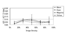
- FIG. 3 is a graph showing changes in the tint of each of the black, cyan, magenta, and yellow colors depending on the substrate temperature.
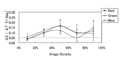
- FIG. 4 is a graph showing changes in the tint of each of the red, green, and blue colors depending on the substrate temperature.
- FIG. 5 is a graph showing the experimental results of investigating the relationship between the substrate temperature and the single streaks caused by dew condensation.
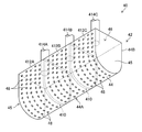
- FIG. 6 is a perspective view schematically showing a configuration example of the non-contact transport unit.
- FIG. 6 is a perspective view schematically showing a configuration example of the non-contact transport unit.
- FIG. 7 is a cross-sectional view schematically showing a configuration example of a temperature control device used for temperature control of a floating transport wind.
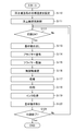
- FIG. 8 is a flowchart showing an example of a method of controlling the floating transport wind.
- FIG. 9 is a block diagram showing an electrical configuration of the printing apparatus.
- FIG. 10 is a block diagram showing the functions of the transport control unit.
- FIG. 11 is a flowchart showing an example of a printed matter manufacturing method according to the embodiment of the present invention.
- FIG. 1 is a diagram schematically showing a configuration of a printing apparatus 10 according to an embodiment of the present invention.
- the printing device 10 is a roll-to-roll inkjet printing device that prints an image on a web-shaped base material 12 by a single-pass method.
- the base material 12 is a non-penetrating medium, for example, a transparent film base material used for flexible packaging.
- non-penetrating means having non-penetration with respect to a water-based primer and a water-based ink described later.
- Flexible packaging refers to packaging made of a material that deforms depending on the shape of the article to be packaged.
- Transparency means that the transmittance of visible light is 30% or more and 100% or less, and preferably 70% or more and 100% or less.
- the base material 12 may be, for example, ONY (Oriented Nylon), OPP (Oriented Poly Propylene), PET (Polyethylene Terephthalate), or the like.
- the printing device 10 manufactures a back-printed printed matter in which a printed image can be visually recognized from the surface of the base material 12 opposite to the printing surface.
- the direction indicated by the arrow A in FIG. 1 indicates the observation direction of the printed image by the user.
- the printing surface of the base material 12 means a base material surface to which ink is applied by inkjet printing.
- the printed matter produced by using the printing apparatus 10 according to the present embodiment is a printed matter in which a printed image is observed from the side of the non-printed surface, which is the side opposite to the printed surface.
- the printing apparatus 10 includes an unwinding section 20, a precoat section 30, a precoat drying section 34, a first non-contact transport section 40, a first suction drum 50, a jetting section 60, and a second suction drum 70. ,
- the second non-contact transport unit 80 and the winding unit 90 are included.
- the transport path of the base material 12 from the unwinding portion 20 to the take-up portion 90 is referred to as a “base material transport route”.
- the transport direction of the base material 12 along the base material transport path is referred to as a “base material transport direction”.
- the "upstream side” means the side close to the unwinding portion 20
- the "downstream side” means the side close to the winding portion 90.
- the contact transport section 80 and the take-up section 90 are arranged in this order.
- the base material transport mechanism 100 that transports the base material 12 unwound from the unwinding portion 20 to the take-up portion 90 along the base material transport path includes a first non-contact transport unit 40, a first suction drum 50, and a second. It is a roll-to-roll transfer mechanism including a suction drum 70 and a second non-contact transfer unit 80.
- the unwinding unit 20 and the winding unit 90 may be included in the base material transport mechanism 100.
- the base material transport mechanism 100 includes one or more elements such as a pass roller (not shown), a drive roller (not shown), and a non-contact transport portion that function as guide rollers. You may.
- the base material transport mechanism 100 can transport the base material 12 at a constant transport speed.
- the unwinding roll 22 is arranged in the unwinding portion 20.
- the unprinting roll 22 is a roll in which the (unprinted) base material 12 before printing is wound in a roll shape.
- the unwinding portion 20 includes an undrawing device (not shown) that rotatably supports the core 23 of the unwinding roll 22, and the base material 12 is unwound from the unwinding roll 22.
- a take-up roll 92 is arranged in the take-up unit 90.
- the take-up roll 92 is a roll in which the printed base material 12 printed by the jetting unit 60 is wound into a roll shape.
- the take-up unit 90 includes a take-up device (not shown), and one end of a base material 12 unwound from the take-up unit 20 is connected to a take-up reel (not shown) held by the take-up device.
- the take-up device includes a take-up motor (not shown) that rotationally drives the take-up reel. By rotating the take-up reel, the base material 12 is taken up by the take-up roll 92.
- the printing apparatus 10 employs a two-component configuration in which the precoating unit 30 applies an undercoating liquid to the base material 12 and then performs inkjet printing before the inkjet printing in the jetting unit 60. That is, the precoat portion 30 is arranged on the upstream side of the base material transport path with respect to the jetting portion 60.
- the ink composition and the undercoat liquid By using the ink composition and the undercoat liquid, inkjet printing can be speeded up, and even when printing at high speed, an image having high density and high resolution and excellent reproducibility of fine lines and fine portions can be obtained.
- a water-based ink is used in inkjet printing, and a water-based primer is used as an undercoat liquid.
- the precoat portion 30 applies an aqueous primer to the printed surface of the base material 12.
- the water-based primer contains water and a component that aggregates or insolubilizes the color material component in the water-based ink or thickens the ink.
- the amount of the water-based primer applied is, for example, about 1/10 of the amount of the water-based ink applied by the jetting unit 60.
- the viscosity of the aqueous primer is, for example, 0.5 cP or more and 5.0 cP or less.
- 1 cP (centipores) is 0.001 Pa ⁇ s (Pascal second).
- a chamber doctor type coater is used for the precoat portion 30, for example.
- the coater includes a coating roller 32, a chamber (not shown), and a blade (not shown).
- the chamber is a container for storing aqueous primers.
- the coating roller 32 is rotated by a motor (not shown).
- An aqueous primer is supplied from the chamber to the surface of the coating roller 32.
- the blade scrapes off excess aqueous primer on the surface of the rotating coating roller 32.
- the coating roller 32 sandwiches the base material 12 with an opposing roller (not shown) and brings the roller surface to which the water-based primer is supplied into contact with the printing surface of the base material 12, so that the water-based primer is printed on the base material 12. Apply to the surface.
- the coater is not limited to the chamber doctor type coater, and a direct gravure coater or a kiss reverse coater may be applied. Further, the method of applying the undercoat liquid is not limited to the roller coating method, and an inkjet method may be adopted.
- the precoat drying section 34 performs a process of drying the aqueous primer applied to the printed surface of the base material 12 by the precoat section 30.
- the precoat drying unit 34 includes a hot air heater (not shown).
- the hot air heater has, for example, a slit nozzle (not shown) over the entire width of the base material 12.
- the precoat drying unit 34 blows warm air from the slit nozzle of the warm air heater toward the printed surface of the base material 12 to dry the aqueous primer.
- the base material 12 on which the aqueous primer has been dried is conveyed to the jetting unit 60 via the first non-contact transfer unit 40 and the first suction drum 50.
- the first non-contact transport unit 40 blows air to the base material 12 to carry out floating transport, and the traveling direction of the base material 12 is set to the print surface side of the base material 12 without contacting the print surface of the base material 12. Performs a direction change to bend in the direction of.
- the first non-contact transport unit 40 shown in FIG. 1 shows an example in which the traveling direction of the base material 12 horizontally transported in the precoat drying unit 34 is turned upward by 90 degrees, but the angle of direction change is 90 degrees. Not limited to this, any angle of 180 degrees or less can be set at an angle exceeding 0 degrees. Details of the first non-contact transport unit 40 will be described later.
- the base material 12 whose traveling direction of the base material 12 is bent by the first non-contact transport unit 40 is transported to the first suction drum 50.
- the first suction drum 50 is arranged on the upstream side of the base material transport path with respect to the jetting portion 60.
- the first suction drum 50 is rotated by a motor (not shown), and the base material 12 is attracted to the outer peripheral surface of the drum and conveyed.
- the first suction drum 50 has a plurality of suction holes (not shown) on the outer peripheral surface of the drum.
- the first suction drum 50 attracts the base material 12 to the outer peripheral surface of the drum by sucking the suction holes by a pump (not shown).
- the base material 12 conveyed by the first suction drum 50 is conveyed to the second suction drum 70.
- the configuration of the second suction drum 70 is the same as that of the first suction drum 50.
- a transfer tension can be applied to the base material 12.
- the transport tension is a tensile force that the base material 12 receives in the traveling direction of the base material 12.
- the jetting unit 60 is arranged in the base material transport path between the first suction drum 50 and the second suction drum 70.
- the jetting unit 60 includes inkjet heads 62K, 62C, 62M, 62Y, and 62W.
- the jetting unit 60 is an example of the “inkjet printing unit” in the present disclosure.
- the inkjet heads 62K, 62C, 62M, 62Y, and 62W are print heads that eject black (K), cyan (C), magenta (M), yellow (Y), and white (W) water-based inks, respectively.
- Aqueous ink refers to an ink in which a coloring material such as a dye or a pigment is dissolved or dispersed in water and a solvent soluble in water.
- a water-based pigment ink is used.
- Organic pigments are used as pigments for each of the CMYK water-based inks.
- Titanium oxide is used as the pigment for the water-based white ink.
- the viscosity of each water-based ink is 0.5 cP or more and 5.0 cP or less.
- the water-based ink thickens by reacting with the water-based primer.
- Water-based ink is supplied to each of the inkjet heads 62K, 62C, 62M, 62Y, and 62W from an ink tank of a corresponding color (not shown) via a piping path (not shown).
- Each of the ink supply systems of the inkjet heads 62K, 62C, 62M, 62Y, and 62W is provided with an ink temperature adjusting device (not shown) for maintaining the ink temperature at a specified ink temperature.
- the ink temperature control device includes a temperature sensor (not shown) that detects the ink temperature, a heater (not shown) that heats the ink, and a controller (not shown) that controls the heater based on the detection signal of the temperature sensor.
- the inkjet heads 62K, 62C, 62M, 62Y, and 62W are line-type print heads that can be printed by one scan on the base material 12 transported by the base material transport mechanism 100.
- a plurality of nozzles which are ink ejection ports, are two-dimensionally arranged on each nozzle surface of the inkjet heads 62K, 62C, 62M, 62Y, and 62W.
- the nozzle surface refers to the discharge surface on which the nozzle is formed.
- a water-repellent film is formed on each nozzle surface of the inkjet heads 62K, 62C, 62M, 62Y, and 62W.
- the inkjet heads 62K, 62C, 62M, 62Y, and 62W can each be configured by connecting a plurality of head modules in the width direction of the base material 12.
- Ink droplets are ejected from at least one of the inkjet heads 62K, 62C, 62M, 62Y, and 62W toward the printing surface of the substrate 12 conveyed by the substrate transfer mechanism 100, and the ejected droplets are discharged.
- an image is printed on the printed surface of the base material 12.
- the ink applied to the printed surface of the base material 12 in the jetting portion 60 undergoes a condensation thickening reaction by the aqueous primer applied to the printed surface of the base material 12 in the precoat portion 30.
- the ink color and the number of colors are not limited to this embodiment.
- an inkjet head that ejects light color inks such as light magenta and light cyan, special color inks such as green, orange, and violet, clear ink, and metallic ink may be added.
- a plurality of inkjet heads that eject ink of the same color may be arranged.
- the arrangement order of the inkjet heads of each color is not particularly limited, but since the white ink is used when printing a white background image, the inkjet head 62W is located downstream of the inkjet head that ejects the non-white ink. It is preferable to be arranged.
- the second non-contact transport section 80 is arranged in the substrate transport path between the second suction drum 70 and the take-up section 90.
- the configuration of the second non-contact transport unit 80 is the same as that of the first non-contact transport unit 40.
- ⁇ E is a color difference in the CIE L * a * b * (CIELAB) color space defined by the Commission internationale de l'eclairage (CIE).
- FIG. 2 is a graph showing data showing the amount of change in color between the color at the lowest temperature (25 ° C. in this case) and the color at each temperature, and an approximate curve thereof.
- the horizontal axis represents the temperature
- the vertical axis represents the color difference ⁇ E.
- FIG. 3 is a graph showing changes in the tint of each of the black, cyan, magenta, and yellow colors depending on the substrate temperature.
- FIG. 4 is a graph showing changes in the tint of each of the red, green, and blue colors depending on the substrate temperature.
- the horizontal axis represents the print density
- the vertical axis represents the amount of color change ( ⁇ E / ⁇ T) per unit temperature.
- ⁇ E / ⁇ T is called "the slope of color with respect to temperature”.
- the print density on the horizontal axis is represented by the halftone dot area ratio.
- the base material 12 used for flexible packaging is generally an extremely thin base material having a thickness of about 20 ⁇ m to 25 ⁇ m, the temperature of the base material 12 at the time of printing is used for floating transportation of the first non-contact transport unit 40. It is considered that the temperature of the wind applied to the base material 12 can be easily followed.
- the temperature of the wind applied to the base material 12 by the first non-contact transport unit 40 is T1 [° C.] and the target temperature in temperature control is Tgt [° C.]
- the temperature T1 is Tgt.
- the target temperature Tgt is preferably set to a value lower than the temperature of the ink ejected from the inkjet head by the jetting unit 60.
- FIG. 5 is a graph showing the experimental results of investigating the relationship between the substrate temperature and the single streaks caused by dew condensation.
- Single-shot streaks are streak-like image defects that occur in printed matter due to poor nozzle ejection.
- the single-shot streak caused by dew condensation means a single-shot streak caused by a nozzle ejection failure caused by dew condensation on the nozzle surface of the print head.
- the horizontal axis of FIG. 5 represents the base material temperature, and the vertical axis represents the number of single streaks caused by dew condensation by the number of streaks generated per 100 sheets.
- the environment in which the experiment was carried out was a temperature of 28 ° C., a humidity of 60% RH, and an ink temperature of 30 ° C.
- the ink temperature is the temperature of the ink discharged from the print head, and may be understood as the temperature of the nozzle surface.
- black ink (P20K) which is a water-based pigment ink, was used.
- the preferable temperature condition of the floating transport wind is equal to or lower than the ink temperature in view of the margin. That is, it is preferable that Tgt + 4 ° C., which is the upper limit temperature of the temperature range of the floating transport wind in the first non-contact transport unit 40, is equal to or lower than the ink temperature.
- FIG. 6 is a perspective view schematically showing a configuration example of the non-contact transport unit.
- an example of a 180-degree turn bar that changes the direction of the base material transport path to a U-shape by 180 degrees is shown, but the basic structure is the same for a turn bar that changes the direction to another angle such as a 90-degree turn bar.
- Each of the first non-contact transport unit 40 and the second non-contact transport unit 80 may adopt substantially the same configuration.
- the first non-contact transport unit 40 will be described.
- the first non-contact transport unit 40 includes a turn bar 42.
- the turn bar 42 includes a transport plate 44 having a U-shaped curved surface along a substrate transport path, two side plates 45 and 45 covering both side surfaces of the transport plate 44 in the width direction, and a rear portion of the transport plate 44. Includes a back plate 46 that covers (the upper end portion in FIG. 2).
- the transport plate 44 includes a curved surface portion 44A curved in an arc shape and a flat surface portion 44B extending from both ends of the arc of the curved surface portion 44A.
- a plurality of outlets 48 for blowing air to the base material 12 are arranged on the curved surface portion 44A and the flat surface portion 44B of the transport plate 44.
- the outlet 48 may be a circular through hole.
- the outlets 48 are arranged in a staggered pattern in the plane of the transport plate 44 at predetermined pitches in the base material width direction and the base material transport direction and directions orthogonal to the base material transport direction.
- the pitch of the outlet 48 is preferably set according to the hole diameter of the outlet 48.
- the inside of the turn bar 42 is divided into a plurality of rooms 412A, 412B, and 412C by partition plates 410 and 410, and the air flow between the rooms is blocked.
- FIG. 6 shows an example in which two partition plates 410 and 410 are used to divide the turn bar 42 into three rooms 412A, 412B, and 412C at equal intervals in the width direction. Not limited to this, an appropriate configuration can be adopted.
- Air supply pipes 414A, 414B, and 414C that supply air to each of the plurality of rooms 412A, 412B, and 412C are connected to the back plate 46.
- a blower (not shown) is connected to the air supply pipes 414A, 414B, and 414C.
- As the turn bar 42 for example, an air turn bar TBA or TBE manufactured by BELLMATIC Co., Ltd. can be used.
- the air supplied to the turn bar 42 via the air supply pipes 414A, 414B, and 414C is blown out from the outlet 48.
- the variation in the temperature of the air blown from the outlet 48 is controlled within ⁇ 4 ° C.
- the base material 12 floats from the transport plate 44 by the air blown from the outlet 48, and is floated and transported to the turn bar 42 without contact.
- levitation transport is synonymous with levitation transport, non-contact transport, or air float transport.
- the air supply pipes 414A, 414B, and 414C are examples of the "gas supply pipes" in the present disclosure.
- FIG. 7 is a cross-sectional view schematically showing a configuration example of the temperature control device 440 used for temperature control of the floating transport wind.
- the temperature control device 440 includes a temperature sensor 442, a heater 444, a Peltier element 446, and a controller 448.
- the temperature sensor 442, the heater 444, and the Peltier element 446 are connected to the controller 448.
- the temperature sensor 442 may be, for example, a thermocouple.
- the temperature sensor 442 is arranged inside the turn bar 42 and detects the temperature of the air blown out from the outlet 48.
- the controller 448 includes a temperature measuring device 449 that measures the temperature of the floating transport air based on the signal obtained from the temperature sensor 442.
- the temperature measuring device 449 may include a display for displaying information on the measured temperature.
- the controller 448 operates the heater 444 and the Peltier element 446 so that the temperature of the floating transport air is within the specified temperature range.
- the controller 448 includes, for example, a processor such as a CPU (Central Processing Unit).
- the heater 444 and the Peltier element 446 are arranged in the air supply pipe 414.
- the air supply pipe 414 represents the air supply pipes 414A, 414B, and 414C shown in FIG.
- a heater 444 and a Peltier element 446 are arranged in each of the plurality of air supply pipes 414A, 414B, and 414C.
- the heater 444 is an example of a heating device that heats air to raise the temperature of the floating transport air.
- the heater 444 is ON / OFF controlled by the controller 448.
- the Peltier element 446 is an example of a cooling device that cools air to lower the temperature of the floating transport air.
- the controller 448 controls the temperature of the floating transport air to a temperature equal to or lower than the ink temperature, and controls the temperature so that the temperature variation is within ⁇ 4 ° C. For example, when the ink temperature is set to 30 ° C., the controller 448 controls the temperature of the floating transport air within the range of 26 ° C. ⁇ 4 ° C. That is, the temperature of the floating transport air is controlled so that the maximum value in the allowable range of temperature variation of ⁇ 4 ° C. is equal to or lower than the ink temperature.
- a precoat layer 33 is formed on the printed surface of the base material 12.
- the base material 12 can be transported without bringing the precoat layer 33 into contact with the transport plate 44.
- the first non-contact transport unit 40 is an example of the “contactless transport unit” in the present disclosure.
- FIG. 8 is a flowchart showing an example of a method of controlling the floating transport wind. The steps in the flowchart shown in FIG. 8 are performed by the controller 448.
- step S11 the controller 448 starts blowing the floating transport air.
- the controller 448 opens an air supply valve (not shown), starts supplying air to the turn bar 42 via the air supply pipe 414, and blows out air from the outlet 48.
- step S12 the controller 448 turns on the power of the heater 444. Further, in step S13, the controller 448 turns on the power of the temperature measuring device 449. After that, the temperature measurement by the temperature measuring device 449 is continued, and the controller 448 constantly monitors the temperature of the floating transport air.
- step S14 the controller 448 determines whether or not printing by the printing device 10 is possible. This determination process is performed based on the flag set in step S16 or step S18, which will be described later.
- the printable state is called the "print OK” state
- the non-printable state is called the "print NG” state. In the initial state immediately after the start of control, it is assumed that the state is "printing NG".
- step S14 determines whether the printing device 10 is in the printing NG state. If the determination result in step S14 is No, that is, when the printing device 10 is in the printing NG state, the controller 448 proceeds to step S15.
- step S15 the controller 448 determines whether or not the temperature of the floating transport air is the printable temperature.
- the printable temperature is specified, for example, in the temperature range of 26 ° C. ⁇ 4 ° C. If the determination result in step S15 is No, the controller 448 proceeds to step S20.
- step S15 the controller 448 proceeds to step S16.
- step S16 the controller 448 sets a flag indicating that the printing device 10 is in the printing OK state.
- the state in which the print OK flag is set indicates that the printing device 10 is permitted to execute printing.
- step S20 controller 448 proceeds to step S20.
- the print is OK, the print job is executed and printing is performed.
- step S14 determines whether or not the temperature of the floating transport air is a non-printable temperature.
- the non-printable temperature means that the temperature is not the printable temperature, that is, the temperature is out of the printable temperature range.
- step S17 the controller 448 determines whether or not the temperature of the floating transport air is a non-printable temperature.
- the non-printable temperature is specified, for example, in the temperature range of 26 ° C. ⁇ 4 ° C.
- the controller 448 proceeds to step S18.
- step S18 the controller 448 sets a flag indicating that the printing device 10 is in the printing NG state.
- the state in which the print NG flag is set indicates that the printing device 10 is prohibited from executing printing.
- controller 448 proceeds to step S20.
- step S17 If the determination result in step S17 is No, the controller 448 proceeds to step S20.
- step S20 the controller 448 determines whether or not the heater power supply is in the ON state. If the determination result in step S20 is Yes determination, the controller 448 proceeds to step S21 to determine whether or not the temperature of the floating transport air is equal to or higher than the designated upper limit temperature.
- the designated upper limit temperature is set to a temperature indicating the upper limit of the temperature range designated as the printable temperature, or a temperature slightly lower than this.
- step S21 If the determination result in step S21 is No, the controller 448 returns to step S14.
- step S21 determines whether the determination result in step S21 is Yes determination. If the determination result in step S21 is Yes determination, the controller 448 proceeds to step S22, turns off the power of the heater 444, and turns on the power of the Peltier element 446. After step S22, controller 448 returns to step S14.
- step S20 determines whether or not the temperature of the floating transport air is equal to or lower than the specified lower limit temperature.
- the designated lower limit temperature is set to a temperature indicating the lower limit of the temperature range designated as the printable temperature, or a temperature slightly higher than this.
- step S23 If the determination result in step S23 is No, the controller 448 returns to step S14.
- step S23 determines whether the determination result in step S23 is Yes determination. If the determination result in step S23 is Yes determination, the controller 448 proceeds to step S24, turns on the power of the heater 444, and turns off the power of the Peltier element 446. After step S24, controller 448 returns to step S14.
- FIG. 9 is a block diagram showing an electrical configuration of the printing apparatus 10.
- the printing device 10 includes a communication unit 202, a user interface 204, a storage unit 206, a general control unit 210, an unwinding control unit 220, a transport control unit 222, a precoat control unit 230, and a precoat drying control unit 234.
- a jetting control unit 260 and a take-up control unit 290 are provided.
- the communication unit 202 includes a wired or wireless communication interface.
- the printing device 10 can acquire image data or the like to be printed via the communication unit 202.
- the user interface 204 includes an input device (not shown) and a display device (not shown) for the user to operate the printing device 10.
- the input device is, for example, an operation panel that receives input from a user.
- various input devices such as a keyboard, a mouse, a touch panel, and a trackball can be adopted, and any combination thereof may be used.
- the display device is, for example, a display that displays image data and various types of information. The user can make the printing device 10 print a desired image by operating the input device.
- the storage unit 206 stores a program for controlling the printing device 10 and information necessary for executing the program.
- the storage unit 206 is composed of a hard disk (not shown) and / or a computer-readable medium which is a non-temporary tangible object such as various semiconductor memories.
- the integrated control unit 210 performs various processes according to the program stored in the storage unit 206, and controls the overall operation of the printing device 10.
- the unwinding control unit 220 controls the rotation of a motor (not shown) in the unwinding unit 20, and controls the unwinding operation of the base material 12.
- the transfer control unit 222 controls the operation of the base material transfer mechanism 100.
- the unwinding portion 20 and the winding portion 90 may be included in the base material transport mechanism 100.
- the transport control unit 222 controls the rotation of a motor or the like (not shown) and rotates the base material 12 at a predetermined speed to transport the base material 12 in a roll-to-roll manner.
- the transport control unit 222 includes the controller 448 described with reference to FIG.
- the precoat control unit 230 controls the coater of the precoat unit 30. That is, the precoat control unit 230 controls the rotation of a motor (not shown) that drives the coating roller 32, rotates the coating roller 32 at a predetermined speed, and applies the aqueous primer to the printed surface of the base material 12 by the coating roller 32. Let me.
- the precoat drying control unit 234 controls the temperature and air volume of the hot air heater provided in the precoat drying unit 34 to dry the undercoat liquid on the base material 12.
- the jetting control unit 260 controls the ink ejection operation of each inkjet head 62K, 62C, 62M, 62Y, 62W in the jetting unit 60 based on the print data.
- the jetting control unit 260 includes an image processing unit that performs various conversion processing, correction processing, halftone processing, and the like on the image data to be printed.
- the conversion process includes pixel number conversion, gradation conversion, color conversion, and the like.
- the correction process includes density correction, non-ejection correction for suppressing the visibility of image defects due to the non-ejection nozzle, and the like.
- the jetting control unit 260 uses the inkjet heads 62K, 62C, 62M, and 62Y to eject droplets of black, cyan, magenta, and yellow water-based inks at the timing when the base material 12 passes through the positions facing the nozzle surfaces. Discharge toward the base material 12. As a result, a color image is printed on the printed surface of the base material 12.
- the jetting control unit 260 ejects droplets of white water-based ink from the inkjet head 62W toward the base material 12 at the timing when the base material 12 passes through a position facing the nozzle surface of the inkjet head 62W.
- a white background image is printed on the printed surface of the base material 12.
- the white background image is not limited to the image printed on the entire surface of the color image area, and may be an image selectively printed with respect to the color image area.
- the take-up control unit 290 controls the rotation of a motor (not shown) in the take-up unit 90, rotates the take-up roll 92, and controls the take-up operation of the base material 12.
- FIG. 10 is a block diagram showing the functions of the transport control unit 222.
- the transfer control unit 222 includes a first non-contact transfer control unit 224, a suction drum control unit 225, and a second non-contact transfer control unit 228.
- the first non-contact transfer control unit 224 controls the temperature of the floating transfer air in the first non-contact transfer unit 40 and the amount of air blown out (air volume) from the outlet 48.
- the first non-contact transfer control unit 224 includes the controller 448 described with reference to FIG.
- the suction drum control unit 225 controls the rotation speed and suction pressure of the first suction drum 50 and the second suction drum 70, respectively.
- the suction drum control unit 225 can function as a tension control unit that controls the transport tension of the base material 12.
- the second non-contact transport control unit 228 controls the amount of air blown from the outlet of the second non-contact transport unit 80.
- the second non-contact transport unit 80 can be in a form in which the temperature of the wind is not controlled, and the temperature sensor 442, the heater 444, and the Peltier element 446 can be omitted.
- FIG. 11 is a flowchart showing an example of a printed matter manufacturing method according to the embodiment of the present invention.
- the flowchart of FIG. 11 may be understood as an example of a printing method implemented by using the printing device 10.
- a printed matter can be produced by performing roll-to-roll inkjet printing using the printing apparatus 10.
- step S110 the first non-contact transfer control unit 224 sets the target temperature of the floating transfer wind.
- This setting may be automatically set to a value specified in advance according to the program, or may be set to a value specified by the user via the user interface 204.
- the target temperature of the floating transport wind may be automatically determined based on the ink temperature at the time of printing.
- a permissible range of ⁇ 4 ° C. variation is set around the specified target temperature, and a printable temperature range is set.
- the setting is not limited to the configuration in which the target temperature as the reference temperature is set, and the lower limit temperature and the upper limit temperature in the allowable range of ⁇ 4 ° C. may be set.
- step S111 the first non-contact transfer control unit 224 starts controlling the floating transfer wind.
- the content of the control process in step S111 may be the flowchart described with reference to FIG.
- the control of the floating transport wind started in step S111 is continuously executed until the printing is completed.
- step S112 the overall control unit 210 determines whether or not printing is OK. This determination process is performed based on the flag set in step S16 or step S18 of FIG. If the determination result in step S113 is No, the overall control unit 210 loops the process of step S112 and waits until the printing is OK.
- step S112 determines whether the print job is print job. If the determination result in step S112 is Yes determination, the overall control unit 210 proceeds to step S112 and executes the designated print job.
- step S113 the base material transport mechanism 100 unwinds the base material 12 from the unwinding roll 22 and transports the base material 12.
- step S114 the precoat portion 30 applies an aqueous primer to the printed surface of the base material 12.
- step S115 the precoat drying section 34 dries the aqueous primer applied to the printed surface of the base material 12.
- step S116 the first non-contact transport unit 40 blows floating transport air onto the printed surface of the base material 12 to change the direction of the base material transport path without contact.
- step S117 the first suction drum 50 attracts the base material 12 from the non-printing surface side and conveys the base material 12.
- step S118 the jetting unit 60 applies ink to the printing surface of the base material 12 and prints an image on the base material 12.
- the region of the base material 12 that has been inkjet printed by the jetting unit 60 is transported to the winding unit 90 via suction transfer by the second suction drum 70 and non-contact transfer by the second non-contact transfer unit 80.
- step S120 the winding unit 90 winds the printed base material 12 on the winding roll 92.
- the printed substrate 12 is an example of the "printed matter" in the present disclosure.
- a step of drying the ink may be added between steps S118 and S120.
- an ink drying section (not shown) is arranged between the second non-contact transport section 80 and the winding section 90 in the base material transport path, and the ink drying section is an ink applied to the printing surface of the base material 12. To dry.
- step S121 the overall control unit 210 determines whether or not to end printing.
- the determination result in step S121 becomes a No determination, and the process returns to step S112.
- the control of the floating transport wind described with reference to FIG. 8 is also executed, and the temperature variation of the floating transport wind of the first non-contact transport unit 40 at the time of printing. Is kept within ⁇ 4 ° C.
- step S121 When printing is completed, such as when the processing of the designated print job is completed, or when the unwinding roll 22 is replaced in the middle of the print job, the determination result in step S121 becomes Yes determination, and the overall control unit 210 ends the flowchart of FIG. In this way, the production of the printed matter is completed.
- the printed matter manufacturing method according to the present embodiment a printed matter having a stable color can be obtained.
- Transporting the base material 12 from the unwinding portion 20 to the winding portion 90 by the base material transporting operation including the base material unwinding operation in step S114 and the base material winding operation in step S120 is a "roll" in the present disclosure. This is an example of "transporting a base material by a two-roll method”.
- the ejector of the inkjet head includes a nozzle for discharging a liquid, a pressure chamber communicating with the nozzle, and a discharge energy generating element for supplying discharge energy to the liquid in the pressure chamber.
- the means for generating the ejection energy is not limited to the piezoelectric element, and various ejection energy generating elements such as a heat generating element and an electrostatic actuator can be applied.
- a method of ejecting droplets by utilizing the pressure of film boiling due to heating of a liquid by a heat generating element can be adopted.
- a corresponding ejection energy generating element is provided in the flow path structure.
- the undercoat liquid may be referred to as a preconditioning liquid, a precoat liquid, a pretreatment liquid, a treatment liquid, or the like.
- the undercoat liquid contains, for example, at least a flocculant that agglomerates the components in the ink composition of the ink, and can be composed of other components as needed.
- the flocculant may be a compound capable of changing the pH of the ink composition, a polyvalent metal salt, or polyallylamines.
- an acidic substance having high water solubility can be used, and an organic acid is preferable, and a divalent or higher organic acid is more preferable, and a divalent organic acid is preferable in terms of enhancing cohesiveness and immobilizing the entire ink.
- Acidic substances having a valence of 3 or more and 3 or less are particularly preferable.
- phosphoric acid, oxalic acid, malonic acid, citric acid and the like are preferably mentioned.
- the flocculant may be used alone or in combination of two or more.
- the undercoat liquid can further contain other additives as other components within a range that does not impair the desired aggregation effect.
- additives include, for example, anti-drying agents (wetting agents), anti-fading agents, emulsion stabilizers, penetration promoters, UV absorbers, preservatives, fungicides, pH regulators, surface tension regulators, defoamers.
- Known additives such as foaming agents, viscosity regulators, dispersants, dispersion stabilizers, rust preventives, chelating agents and the like can be mentioned.
- CPU Central Processing Unit
- FPGA Field Programmable Gate Array
- a dedicated electric circuit which is a processor having a circuit configuration specially designed for executing a specific process such as a programmable logic device (PLD) or an ASIC (Application Specific Integrated Circuit), is included.
- PLD programmable logic device
- ASIC Application Specific Integrated Circuit
- One processing unit may be composed of one of these various processors, or may be composed of two or more processors of the same type or different types.
- one processing unit may be composed of a plurality of FPGAs or a combination of a CPU and an FPGA.
- a plurality of processing units may be configured by one processor.
- one processor is configured by a combination of one or more CPUs and software, as represented by a computer such as a client or a server. There is a form in which the processor functions as a plurality of processing units.
- SoC System On Chip
- IC Integrated Circuit
- the variation in the temperature of the wind applied to the base material 12 in the floating transfer before the inkjet printing is performed by the jetting unit 60 is suppressed within ⁇ 4 ° C.
- the change in color is suppressed, and an image with stable color that satisfies ⁇ E ⁇ 2 can be obtained.
- the temperature of the base material 12 can be controlled without contact by controlling the temperature of the floating transport air, so that the temperature of the base material is controlled by using a contact type heating roller or the like.
- the temperature control followability (responsiveness) is high, and the temperature of the base material 12 can be stabilized during inkjet printing.
- ⁇ Modification 1 The configuration of the printing apparatus 10 described with reference to FIG. 1 can be variously modified.
- a surface modification portion that performs surface modification such as corona treatment in the substrate transport path between the unwind portion 20 and the precoat portion 30.
- the printing apparatus 10 may include an ink drying unit and an image inspection unit between the jetting unit 60 and the winding unit 90.
- the printing device 10 includes an ink drying control unit (not shown) that controls the ink drying unit, and an image inspection control unit (not shown) that controls the image inspection unit.
- the ink drying unit includes a hot air heater that dries the ink applied to the printing surface of the base material 12.
- the ink drying control unit controls the temperature and air volume of the hot air heater to dry the ink on the base material 12.
- the image inspection unit includes an imaging device that captures an image printed on the base material 12.
- the image inspection unit can read the test pattern image printed on the base material 12 and perform a process of identifying a defective nozzle from the read image. Further, the image inspection unit reads an image to be printed printed on the base material 12 and performs a print image inspection process for inspecting whether or not there is an image defect such as a streak in the image based on the read image. be able to.
- the "printable image” here refers to an image corresponding to the image data for printing specified in the print job, and refers to an image for printing purposes specified by the user.
- the image inspection control unit controls the image reading operation by the image inspection unit and processes the obtained read image.
- ⁇ Modification 5 By suppressing the variation in the temperature of the floating transport wind within a range narrower than ⁇ 4 ° C., for example, by suppressing it within ⁇ 3 ° C., the change in color can be further suppressed.
- the base material may be an opaque film base material, and is not limited to back-printing printing, but from the printing surface side. It may be a printing apparatus that manufactures a printed matter for observing a printed image.
- one side of the base material 12 is a printed surface and the other side is a non-printed surface, but the present invention can also be applied to a printing apparatus that performs double-sided printing.
- the second surface is understood as the "printing surface" when the second surface is printed. ..
- ⁇ Modification 9 >>
- the single-pass inkjet printing apparatus has been described, but the scope of application of the present invention is not limited to this, and a plurality of short print heads such as a serial type (shuttle scan type) head may be moved.
- the present invention can also be applied to a printing apparatus that records an image by scanning the head a number of times.
- the base material transport mechanism may adopt a configuration in which the base material is intermittently transported.
- the heads When a color image is formed using an inkjet print head, the heads may be arranged for each color of a plurality of colors of ink, or a configuration capable of ejecting a plurality of colors of ink from one print head may be used. Good.
- the term "printing device” is synonymous with terms such as a printing machine, a printer, a printing device, an image recording device, an image forming device, an image output device, or a drawing device.
- “Image” shall be interpreted in a broad sense, and includes color images, black-and-white images, single-color images, gradation images, uniform density (solid) images, and the like.
- “Image” is not limited to a photographic image, but is used as a comprehensive term including a pattern, characters, symbols, line drawings, mosaic patterns, color-coded patterns, various other patterns, or an appropriate combination thereof.
- printing includes the concepts of terms such as image recording, image formation, printing, drawing, and printing.
- device includes the concept of the term “system”.
- Printing device 12 Base material 20 Unwinding part 22 Unwinding roll 23 Core 30 Precoat part 32 Coating roller 33 Precoat layer 34 Precoat drying part 40 First non-contact transfer part 42 Turn bar 44 Transport plate 44A Curved surface part 44B Flat part 45 Side plate 46 Rear back plate 48 Air outlet 50 1st suction drum 60 Jetting part 62K Inkjet head 62C Inkjet head 62M Inkjet head 62Y Inkjet head 62W Inkjet head 70 2nd suction drum 80 2nd contactless transport part 90 Winding part 92 Winding roll 100 Substrate transfer mechanism 202 Communication unit 204 User interface 206 Storage unit 210 General control unit 220 Unwinding control unit 222 Transfer control unit 224 First contactless transfer control unit 225 Suction drum control unit 228 Second contactless transfer control unit 230 Precoat control Unit 234 Precoat drying control unit 260 Jetting control unit 290 Winding control unit 410 Partition plate 412A, 412B, 412C Room 414, 414A, 414B, 414C Air
Landscapes
- Physics & Mathematics (AREA)
- Fluid Mechanics (AREA)
- Ink Jet (AREA)
- Accessory Devices And Overall Control Thereof (AREA)
- Registering, Tensioning, Guiding Webs, And Rollers Therefor (AREA)
Priority Applications (1)
| Application Number | Priority Date | Filing Date | Title |
|---|---|---|---|
| JP2021563933A JP7320077B2 (ja) | 2019-12-11 | 2020-12-07 | 印刷装置及び方法並びに印刷物製造方法 |
Applications Claiming Priority (2)
| Application Number | Priority Date | Filing Date | Title |
|---|---|---|---|
| JP2019-223638 | 2019-12-11 | ||
| JP2019223638 | 2019-12-11 |
Publications (1)
| Publication Number | Publication Date |
|---|---|
| WO2021117650A1 true WO2021117650A1 (ja) | 2021-06-17 |
Family
ID=76330383
Family Applications (1)
| Application Number | Title | Priority Date | Filing Date |
|---|---|---|---|
| PCT/JP2020/045363 Ceased WO2021117650A1 (ja) | 2019-12-11 | 2020-12-07 | 印刷装置及び方法並びに印刷物製造方法 |
Country Status (2)
| Country | Link |
|---|---|
| JP (1) | JP7320077B2 (https=) |
| WO (1) | WO2021117650A1 (https=) |
Citations (6)
| Publication number | Priority date | Publication date | Assignee | Title |
|---|---|---|---|---|
| JP2001262459A (ja) * | 2000-03-15 | 2001-09-26 | Konica Corp | インクジェット布帛捺染装置 |
| US20180026234A1 (en) * | 2016-07-21 | 2018-01-25 | Kateeva, Inc. | Methods of forming a polymeric thin film layer on an organic light-emitting diode substrate |
| JP2019031019A (ja) * | 2017-08-08 | 2019-02-28 | 株式会社リコー | 搬送装置、画像形成装置、液体を吐出する装置 |
| JP2019119609A (ja) * | 2017-12-28 | 2019-07-22 | 株式会社Screenホールディングス | 印刷装置 |
| JP2019162870A (ja) * | 2018-03-16 | 2019-09-26 | 株式会社リコー | 乾燥装置、液体吐出装置、乾燥方法、及びインクジェット記録装置 |
| WO2019188243A1 (ja) * | 2018-03-26 | 2019-10-03 | 富士フイルム株式会社 | 画像形成装置 |
-
2020
- 2020-12-07 JP JP2021563933A patent/JP7320077B2/ja active Active
- 2020-12-07 WO PCT/JP2020/045363 patent/WO2021117650A1/ja not_active Ceased
Patent Citations (6)
| Publication number | Priority date | Publication date | Assignee | Title |
|---|---|---|---|---|
| JP2001262459A (ja) * | 2000-03-15 | 2001-09-26 | Konica Corp | インクジェット布帛捺染装置 |
| US20180026234A1 (en) * | 2016-07-21 | 2018-01-25 | Kateeva, Inc. | Methods of forming a polymeric thin film layer on an organic light-emitting diode substrate |
| JP2019031019A (ja) * | 2017-08-08 | 2019-02-28 | 株式会社リコー | 搬送装置、画像形成装置、液体を吐出する装置 |
| JP2019119609A (ja) * | 2017-12-28 | 2019-07-22 | 株式会社Screenホールディングス | 印刷装置 |
| JP2019162870A (ja) * | 2018-03-16 | 2019-09-26 | 株式会社リコー | 乾燥装置、液体吐出装置、乾燥方法、及びインクジェット記録装置 |
| WO2019188243A1 (ja) * | 2018-03-26 | 2019-10-03 | 富士フイルム株式会社 | 画像形成装置 |
Also Published As
| Publication number | Publication date |
|---|---|
| JPWO2021117650A1 (https=) | 2021-06-17 |
| JP7320077B2 (ja) | 2023-08-02 |
Similar Documents
| Publication | Publication Date | Title |
|---|---|---|
| US7712889B2 (en) | Image forming apparatus and liquid removal capability setting method | |
| JP5202663B2 (ja) | マット剤塗布装置およびインクジェット記録装置 | |
| US20090244237A1 (en) | Inkjet recording apparatus and inkjet recording method | |
| US8690313B2 (en) | Conveying device and image forming apparatus | |
| JPWO2009148102A1 (ja) | 画像形成方法および画像形成装置 | |
| WO2018143052A1 (ja) | 印刷装置 | |
| US8733881B2 (en) | Inkjet recording method | |
| US9056495B2 (en) | System and method for imaging and evaluating coating on an imaging surface in an aqueous inkjet printer | |
| JP2011073295A (ja) | ヘッド洗浄装置及び画像記録装置 | |
| JP7522827B2 (ja) | 搬送装置、乾燥装置及び印刷装置 | |
| JP2013027981A (ja) | 画像形成装置、及び画像形成方法 | |
| JP5400658B2 (ja) | インクジェット記録装置及びインクジェット記録方法 | |
| WO2021090719A1 (ja) | 印刷装置、搬送装置、及び印刷物の製造方法 | |
| JP7807455B2 (ja) | エアバー、乾燥装置、及びインクジェット印刷装置 | |
| JP7320077B2 (ja) | 印刷装置及び方法並びに印刷物製造方法 | |
| JPWO2018221130A1 (ja) | 印刷装置、乾燥制御方法、及び乾燥制御装置 | |
| US12485686B2 (en) | Inkjet printing device and printing method for printing an image on a continuous medium | |
| JP2010260237A (ja) | 記録装置および判定方法 | |
| JP2023071340A (ja) | 色調整装置及び方法、情報処理装置、プログラム、印刷システム並びに印刷物の製造方法 | |
| JP7402773B2 (ja) | 塗布装置及びインクジェット印刷装置 | |
| JP7241711B2 (ja) | インクジェット印刷装置及び乾燥方法 | |
| JP2015212039A (ja) | 記録装置およびデータ生成装置および記録方法 | |
| WO2022107610A1 (ja) | 印刷システム、印刷方法、搬送システム及び搬送方法 | |
| JP2025090176A (ja) | インクジェット式画像形成装置 | |
| CN119261408A (zh) | 图像形成装置 |
Legal Events
| Date | Code | Title | Description |
|---|---|---|---|
| 121 | Ep: the epo has been informed by wipo that ep was designated in this application |
Ref document number: 20900563 Country of ref document: EP Kind code of ref document: A1 |
|
| ENP | Entry into the national phase |
Ref document number: 2021563933 Country of ref document: JP Kind code of ref document: A |
|
| NENP | Non-entry into the national phase |
Ref country code: DE |
|
| 122 | Ep: pct application non-entry in european phase |
Ref document number: 20900563 Country of ref document: EP Kind code of ref document: A1 |