WO2021117650A1 - Printing device and method, and method for producing printed work - Google Patents
Printing device and method, and method for producing printed work Download PDFInfo
- Publication number
- WO2021117650A1 WO2021117650A1 PCT/JP2020/045363 JP2020045363W WO2021117650A1 WO 2021117650 A1 WO2021117650 A1 WO 2021117650A1 JP 2020045363 W JP2020045363 W JP 2020045363W WO 2021117650 A1 WO2021117650 A1 WO 2021117650A1
- Authority
- WO
- WIPO (PCT)
- Prior art keywords
- base material
- temperature
- printing
- transport
- ink
- Prior art date
Links
Images


Classifications
-
- B—PERFORMING OPERATIONS; TRANSPORTING
- B41—PRINTING; LINING MACHINES; TYPEWRITERS; STAMPS
- B41J—TYPEWRITERS; SELECTIVE PRINTING MECHANISMS, i.e. MECHANISMS PRINTING OTHERWISE THAN FROM A FORME; CORRECTION OF TYPOGRAPHICAL ERRORS
- B41J15/00—Devices or arrangements of selective printing mechanisms, e.g. ink-jet printers or thermal printers, specially adapted for supporting or handling copy material in continuous form, e.g. webs
- B41J15/04—Supporting, feeding, or guiding devices; Mountings for web rolls or spindles
-
- B—PERFORMING OPERATIONS; TRANSPORTING
- B41—PRINTING; LINING MACHINES; TYPEWRITERS; STAMPS
- B41J—TYPEWRITERS; SELECTIVE PRINTING MECHANISMS, i.e. MECHANISMS PRINTING OTHERWISE THAN FROM A FORME; CORRECTION OF TYPOGRAPHICAL ERRORS
- B41J2/00—Typewriters or selective printing mechanisms characterised by the printing or marking process for which they are designed
- B41J2/005—Typewriters or selective printing mechanisms characterised by the printing or marking process for which they are designed characterised by bringing liquid or particles selectively into contact with a printing material
- B41J2/01—Ink jet
- B41J2/21—Ink jet for multi-colour printing
-
- B—PERFORMING OPERATIONS; TRANSPORTING
- B65—CONVEYING; PACKING; STORING; HANDLING THIN OR FILAMENTARY MATERIAL
- B65H—HANDLING THIN OR FILAMENTARY MATERIAL, e.g. SHEETS, WEBS, CABLES
- B65H20/00—Advancing webs
- B65H20/10—Advancing webs by a feed band against which web is held by fluid pressure, e.g. suction or air blast
-
- B—PERFORMING OPERATIONS; TRANSPORTING
- B65—CONVEYING; PACKING; STORING; HANDLING THIN OR FILAMENTARY MATERIAL
- B65H—HANDLING THIN OR FILAMENTARY MATERIAL, e.g. SHEETS, WEBS, CABLES
- B65H23/00—Registering, tensioning, smoothing or guiding webs
- B65H23/04—Registering, tensioning, smoothing or guiding webs longitudinally
- B65H23/32—Arrangements for turning or reversing webs
Definitions
- the present invention relates to a printing apparatus and method, and a printed matter manufacturing method, and particularly relates to a printing technique for performing inkjet printing on a substrate by a roll-to-roll method.
- Patent Document 1 and Patent Document 2 describe a printing apparatus that performs inkjet printing on a base material for flexible packaging conveyed by a roll-to-roll method.
- roll-to-roll transfer when the direction of bending the transfer path of the base material toward the print surface side of the base material is changed by avoiding contact between the printed surface of the base material and the roller for transfer, wind is blown from the roller surface.
- wind is blown from the roller surface.
- a technique of blowing out and transporting the base material in a state of floating from the roller surface There is known a technique of blowing out and transporting the base material in a state of floating from the roller surface.
- the technique of performing non-contact transportation by floating the base material by the force of wind is described as "floating transportation".
- Patent Document 3-4 describes a configuration in which floating transfer is performed in a roll-to-roll method.
- back printing printing may be performed in which an image printed on the printed surface of a transparent substrate is visually recognized through the substrate from the surface opposite to the printed surface.
- the transfer direction of the base material can be bent in any direction without contact by adopting a floating transfer device such as an air turn bar.
- the base material is exposed to wind, so the temperature of the base material changes depending on the temperature of this wind.
- inkjet printing when the temperature of the base material during printing changes, the spread of ink dots adhering to the base material changes, and the tint of the printed color changes. When such a change in color occurs, the color of the printed image will be slightly different even if the same image is printed.
- Patent Document 1-4 although there is a description about the configuration for performing floating transport, there is no description about the variation in temperature of the wind applied to the base material in the floating transport before printing (hereinafter referred to as "floating transport wind"). .. Further, Patent Document 1-4 does not describe the problem of the color change of the printed matter due to the change in the temperature of the floating transport wind in the floating transport before printing.
- the present invention has been made in view of such circumstances, and is a printing apparatus capable of suppressing a change in color to obtain a stable color image in roll-to-roll inkjet printing in which floating transfer is performed. It is an object of the present invention to provide a method as well as a method for producing printed matter.
- the printing apparatus floats and conveys the base material by blowing gas onto the unwinding portion that unwinds the web-shaped base material and the base material unwound from the unwinding portion.
- a temperature control device for controlling the temperature of the gas blown out from the contact transfer unit within a range of ⁇ 4 ° C. is provided.
- the temperature variation of the gas blown out to the base material is suppressed in the non-contact transport part upstream of the inkjet printing part in the transport path of the base material, so that the base material in the inkjet printing part
- the variation in the temperature of the base material when applying ink to the printing sheet is suppressed.
- the gas blown out to the base material by the non-contact transport unit may be paraphrased as "floating transport wind".
- the descriptions such as "floating transport wind” and “wind” mean the flow of gas, and the type of gas is not limited to air unless otherwise specified.
- the temperature of the gas blown out from the non-contact transport section is preferably equal to or lower than the temperature of the ink ejected from the inkjet printing section. According to this aspect, it is possible to suppress ink ejection defects caused by dew condensation on the print head (inkjet head) that ejects ink, and it is possible to suppress the occurrence of image defects due to dew condensation.
- a precoat portion for applying the undercoat liquid to the base material is further provided, and the precoat part is arranged at a position upstream of the position of the inkjet printing part in the transport path of the base material. be able to.
- the undercoat liquid By using the undercoat liquid, it is possible to suppress the spread and / or movement of ink dots on the base material.
- the precoat portion may be arranged at a position upstream of the position of the non-contact transport portion in the transport path of the base material. According to this aspect, since the base material to which the undercoat liquid is applied is conveyed without contact, there is no concern that the undercoat liquid is transferred from the base material to a roller or the like, and high quality printing is possible.
- the precoat drying section further comprises a precoat drying section for drying the undercoat liquid applied to the substrate, and the precoat drying section is between the precoat section and the non-contact transport section in the transport path of the substrate. It can be configured to be placed at a position.
- the pre-coated drying portion may have, for example, a configuration in which warm air is blown to the base material.
- the undercoat liquid can be configured to contain a component that aggregates or insolubilizes the color material component in the ink or thickens the ink by reacting with the ink.
- the reaction rate between the ink and the undercoat liquid is stabilized by suppressing the variation in the temperature of the gas applied to the base material to which the undercoat liquid is applied.
- the temperature controller comprises a temperature sensor for detecting the temperature of the gas, a heater for heating the gas, a cooling device for cooling the gas, and a heater and a cooling device based on a signal from the temperature sensor. It can be configured to include a controller that controls the temperature.
- a gas supply pipe for supplying gas to the non-contact transport portion may be further provided, and the heater and the cooling device may be arranged in the gas supply pipe.
- the gas blown out to the base material in the non-contact transport section may be air.
- the non-contact transfer unit can be configured to change the direction of the transfer path of the base material toward the printing surface side of the base material.
- the base material may be a non-permeable film base material.
- the inkjet printing unit can be configured to include a plurality of inkjet heads that eject each of a plurality of colors of ink.
- the inkjet printing unit can be configured to include an inkjet head that ejects white ink. According to such an aspect, back printing can be performed on a transparent base material, and a white background can be printed with white ink.
- the web-like base material is unwound from the unwinding roll, and the base material is levitated by blowing gas onto the base material unwound from the unwinding roll.
- the non-contact transfer is performed, ink is ejected from the inkjet head to the substrate that has passed through the non-contact transfer portion in the transfer path of the substrate to perform printing, and the substrate printed by the inkjet head is printed.
- This includes winding the ink on a winding roll and controlling the temperature so that the temperature variation of the gas applied to the substrate during non-contact transportation is within ⁇ 4 ° C.
- the base material is transported by a roll-to-roll method, and the base material is levitated by blowing gas to the base material in a part of the transport path of the base material.
- Ink is ejected from the inkjet head to the substrate that has passed through the non-contact transport portion in the transport path of the substrate for printing, and the substrate is hit against the substrate during non-contact transport.
- the change in the color of the printed image is suppressed, and the printed matter of the image having a stable color can be manufactured.
- the base material to be printed may be a transparent film base material used for flexible packaging.
- a change in color tint in inkjet printing is suppressed, and a stable tint image can be obtained.
- FIG. 1 is a diagram schematically showing a configuration of a printing apparatus according to an embodiment of the present invention.
- FIG. 2 is a graph showing data showing the amount of change in color between the color at 25 ° C. and the color at each temperature, and an approximate curve thereof.
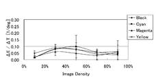
- FIG. 3 is a graph showing changes in the tint of each of the black, cyan, magenta, and yellow colors depending on the substrate temperature.
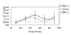
- FIG. 4 is a graph showing changes in the tint of each of the red, green, and blue colors depending on the substrate temperature.
- FIG. 5 is a graph showing the experimental results of investigating the relationship between the substrate temperature and the single streaks caused by dew condensation.
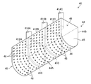
- FIG. 6 is a perspective view schematically showing a configuration example of the non-contact transport unit.
- FIG. 6 is a perspective view schematically showing a configuration example of the non-contact transport unit.
- FIG. 7 is a cross-sectional view schematically showing a configuration example of a temperature control device used for temperature control of a floating transport wind.
- FIG. 8 is a flowchart showing an example of a method of controlling the floating transport wind.
- FIG. 9 is a block diagram showing an electrical configuration of the printing apparatus.
- FIG. 10 is a block diagram showing the functions of the transport control unit.
- FIG. 11 is a flowchart showing an example of a printed matter manufacturing method according to the embodiment of the present invention.
- FIG. 1 is a diagram schematically showing a configuration of a printing apparatus 10 according to an embodiment of the present invention.
- the printing device 10 is a roll-to-roll inkjet printing device that prints an image on a web-shaped base material 12 by a single-pass method.
- the base material 12 is a non-penetrating medium, for example, a transparent film base material used for flexible packaging.
- non-penetrating means having non-penetration with respect to a water-based primer and a water-based ink described later.
- Flexible packaging refers to packaging made of a material that deforms depending on the shape of the article to be packaged.
- Transparency means that the transmittance of visible light is 30% or more and 100% or less, and preferably 70% or more and 100% or less.
- the base material 12 may be, for example, ONY (Oriented Nylon), OPP (Oriented Poly Propylene), PET (Polyethylene Terephthalate), or the like.
- the printing device 10 manufactures a back-printed printed matter in which a printed image can be visually recognized from the surface of the base material 12 opposite to the printing surface.
- the direction indicated by the arrow A in FIG. 1 indicates the observation direction of the printed image by the user.
- the printing surface of the base material 12 means a base material surface to which ink is applied by inkjet printing.
- the printed matter produced by using the printing apparatus 10 according to the present embodiment is a printed matter in which a printed image is observed from the side of the non-printed surface, which is the side opposite to the printed surface.
- the printing apparatus 10 includes an unwinding section 20, a precoat section 30, a precoat drying section 34, a first non-contact transport section 40, a first suction drum 50, a jetting section 60, and a second suction drum 70. ,
- the second non-contact transport unit 80 and the winding unit 90 are included.
- the transport path of the base material 12 from the unwinding portion 20 to the take-up portion 90 is referred to as a “base material transport route”.
- the transport direction of the base material 12 along the base material transport path is referred to as a “base material transport direction”.
- the "upstream side” means the side close to the unwinding portion 20
- the "downstream side” means the side close to the winding portion 90.
- the contact transport section 80 and the take-up section 90 are arranged in this order.
- the base material transport mechanism 100 that transports the base material 12 unwound from the unwinding portion 20 to the take-up portion 90 along the base material transport path includes a first non-contact transport unit 40, a first suction drum 50, and a second. It is a roll-to-roll transfer mechanism including a suction drum 70 and a second non-contact transfer unit 80.
- the unwinding unit 20 and the winding unit 90 may be included in the base material transport mechanism 100.
- the base material transport mechanism 100 includes one or more elements such as a pass roller (not shown), a drive roller (not shown), and a non-contact transport portion that function as guide rollers. You may.
- the base material transport mechanism 100 can transport the base material 12 at a constant transport speed.
- the unwinding roll 22 is arranged in the unwinding portion 20.
- the unprinting roll 22 is a roll in which the (unprinted) base material 12 before printing is wound in a roll shape.
- the unwinding portion 20 includes an undrawing device (not shown) that rotatably supports the core 23 of the unwinding roll 22, and the base material 12 is unwound from the unwinding roll 22.
- a take-up roll 92 is arranged in the take-up unit 90.
- the take-up roll 92 is a roll in which the printed base material 12 printed by the jetting unit 60 is wound into a roll shape.
- the take-up unit 90 includes a take-up device (not shown), and one end of a base material 12 unwound from the take-up unit 20 is connected to a take-up reel (not shown) held by the take-up device.
- the take-up device includes a take-up motor (not shown) that rotationally drives the take-up reel. By rotating the take-up reel, the base material 12 is taken up by the take-up roll 92.
- the printing apparatus 10 employs a two-component configuration in which the precoating unit 30 applies an undercoating liquid to the base material 12 and then performs inkjet printing before the inkjet printing in the jetting unit 60. That is, the precoat portion 30 is arranged on the upstream side of the base material transport path with respect to the jetting portion 60.
- the ink composition and the undercoat liquid By using the ink composition and the undercoat liquid, inkjet printing can be speeded up, and even when printing at high speed, an image having high density and high resolution and excellent reproducibility of fine lines and fine portions can be obtained.
- a water-based ink is used in inkjet printing, and a water-based primer is used as an undercoat liquid.
- the precoat portion 30 applies an aqueous primer to the printed surface of the base material 12.
- the water-based primer contains water and a component that aggregates or insolubilizes the color material component in the water-based ink or thickens the ink.
- the amount of the water-based primer applied is, for example, about 1/10 of the amount of the water-based ink applied by the jetting unit 60.
- the viscosity of the aqueous primer is, for example, 0.5 cP or more and 5.0 cP or less.
- 1 cP (centipores) is 0.001 Pa ⁇ s (Pascal second).
- a chamber doctor type coater is used for the precoat portion 30, for example.
- the coater includes a coating roller 32, a chamber (not shown), and a blade (not shown).
- the chamber is a container for storing aqueous primers.
- the coating roller 32 is rotated by a motor (not shown).
- An aqueous primer is supplied from the chamber to the surface of the coating roller 32.
- the blade scrapes off excess aqueous primer on the surface of the rotating coating roller 32.
- the coating roller 32 sandwiches the base material 12 with an opposing roller (not shown) and brings the roller surface to which the water-based primer is supplied into contact with the printing surface of the base material 12, so that the water-based primer is printed on the base material 12. Apply to the surface.
- the coater is not limited to the chamber doctor type coater, and a direct gravure coater or a kiss reverse coater may be applied. Further, the method of applying the undercoat liquid is not limited to the roller coating method, and an inkjet method may be adopted.
- the precoat drying section 34 performs a process of drying the aqueous primer applied to the printed surface of the base material 12 by the precoat section 30.
- the precoat drying unit 34 includes a hot air heater (not shown).
- the hot air heater has, for example, a slit nozzle (not shown) over the entire width of the base material 12.
- the precoat drying unit 34 blows warm air from the slit nozzle of the warm air heater toward the printed surface of the base material 12 to dry the aqueous primer.
- the base material 12 on which the aqueous primer has been dried is conveyed to the jetting unit 60 via the first non-contact transfer unit 40 and the first suction drum 50.
- the first non-contact transport unit 40 blows air to the base material 12 to carry out floating transport, and the traveling direction of the base material 12 is set to the print surface side of the base material 12 without contacting the print surface of the base material 12. Performs a direction change to bend in the direction of.
- the first non-contact transport unit 40 shown in FIG. 1 shows an example in which the traveling direction of the base material 12 horizontally transported in the precoat drying unit 34 is turned upward by 90 degrees, but the angle of direction change is 90 degrees. Not limited to this, any angle of 180 degrees or less can be set at an angle exceeding 0 degrees. Details of the first non-contact transport unit 40 will be described later.
- the base material 12 whose traveling direction of the base material 12 is bent by the first non-contact transport unit 40 is transported to the first suction drum 50.
- the first suction drum 50 is arranged on the upstream side of the base material transport path with respect to the jetting portion 60.
- the first suction drum 50 is rotated by a motor (not shown), and the base material 12 is attracted to the outer peripheral surface of the drum and conveyed.
- the first suction drum 50 has a plurality of suction holes (not shown) on the outer peripheral surface of the drum.
- the first suction drum 50 attracts the base material 12 to the outer peripheral surface of the drum by sucking the suction holes by a pump (not shown).
- the base material 12 conveyed by the first suction drum 50 is conveyed to the second suction drum 70.
- the configuration of the second suction drum 70 is the same as that of the first suction drum 50.
- a transfer tension can be applied to the base material 12.
- the transport tension is a tensile force that the base material 12 receives in the traveling direction of the base material 12.
- the jetting unit 60 is arranged in the base material transport path between the first suction drum 50 and the second suction drum 70.
- the jetting unit 60 includes inkjet heads 62K, 62C, 62M, 62Y, and 62W.
- the jetting unit 60 is an example of the “inkjet printing unit” in the present disclosure.
- the inkjet heads 62K, 62C, 62M, 62Y, and 62W are print heads that eject black (K), cyan (C), magenta (M), yellow (Y), and white (W) water-based inks, respectively.
- Aqueous ink refers to an ink in which a coloring material such as a dye or a pigment is dissolved or dispersed in water and a solvent soluble in water.
- a water-based pigment ink is used.
- Organic pigments are used as pigments for each of the CMYK water-based inks.
- Titanium oxide is used as the pigment for the water-based white ink.
- the viscosity of each water-based ink is 0.5 cP or more and 5.0 cP or less.
- the water-based ink thickens by reacting with the water-based primer.
- Water-based ink is supplied to each of the inkjet heads 62K, 62C, 62M, 62Y, and 62W from an ink tank of a corresponding color (not shown) via a piping path (not shown).
- Each of the ink supply systems of the inkjet heads 62K, 62C, 62M, 62Y, and 62W is provided with an ink temperature adjusting device (not shown) for maintaining the ink temperature at a specified ink temperature.
- the ink temperature control device includes a temperature sensor (not shown) that detects the ink temperature, a heater (not shown) that heats the ink, and a controller (not shown) that controls the heater based on the detection signal of the temperature sensor.
- the inkjet heads 62K, 62C, 62M, 62Y, and 62W are line-type print heads that can be printed by one scan on the base material 12 transported by the base material transport mechanism 100.
- a plurality of nozzles which are ink ejection ports, are two-dimensionally arranged on each nozzle surface of the inkjet heads 62K, 62C, 62M, 62Y, and 62W.
- the nozzle surface refers to the discharge surface on which the nozzle is formed.
- a water-repellent film is formed on each nozzle surface of the inkjet heads 62K, 62C, 62M, 62Y, and 62W.
- the inkjet heads 62K, 62C, 62M, 62Y, and 62W can each be configured by connecting a plurality of head modules in the width direction of the base material 12.
- Ink droplets are ejected from at least one of the inkjet heads 62K, 62C, 62M, 62Y, and 62W toward the printing surface of the substrate 12 conveyed by the substrate transfer mechanism 100, and the ejected droplets are discharged.
- an image is printed on the printed surface of the base material 12.
- the ink applied to the printed surface of the base material 12 in the jetting portion 60 undergoes a condensation thickening reaction by the aqueous primer applied to the printed surface of the base material 12 in the precoat portion 30.
- the ink color and the number of colors are not limited to this embodiment.
- an inkjet head that ejects light color inks such as light magenta and light cyan, special color inks such as green, orange, and violet, clear ink, and metallic ink may be added.
- a plurality of inkjet heads that eject ink of the same color may be arranged.
- the arrangement order of the inkjet heads of each color is not particularly limited, but since the white ink is used when printing a white background image, the inkjet head 62W is located downstream of the inkjet head that ejects the non-white ink. It is preferable to be arranged.
- the second non-contact transport section 80 is arranged in the substrate transport path between the second suction drum 70 and the take-up section 90.
- the configuration of the second non-contact transport unit 80 is the same as that of the first non-contact transport unit 40.
- ⁇ E is a color difference in the CIE L * a * b * (CIELAB) color space defined by the Commission internationale de l'eclairage (CIE).
- FIG. 2 is a graph showing data showing the amount of change in color between the color at the lowest temperature (25 ° C. in this case) and the color at each temperature, and an approximate curve thereof.
- the horizontal axis represents the temperature
- the vertical axis represents the color difference ⁇ E.
- FIG. 3 is a graph showing changes in the tint of each of the black, cyan, magenta, and yellow colors depending on the substrate temperature.
- FIG. 4 is a graph showing changes in the tint of each of the red, green, and blue colors depending on the substrate temperature.
- the horizontal axis represents the print density
- the vertical axis represents the amount of color change ( ⁇ E / ⁇ T) per unit temperature.
- ⁇ E / ⁇ T is called "the slope of color with respect to temperature”.
- the print density on the horizontal axis is represented by the halftone dot area ratio.
- the base material 12 used for flexible packaging is generally an extremely thin base material having a thickness of about 20 ⁇ m to 25 ⁇ m, the temperature of the base material 12 at the time of printing is used for floating transportation of the first non-contact transport unit 40. It is considered that the temperature of the wind applied to the base material 12 can be easily followed.
- the temperature of the wind applied to the base material 12 by the first non-contact transport unit 40 is T1 [° C.] and the target temperature in temperature control is Tgt [° C.]
- the temperature T1 is Tgt.
- the target temperature Tgt is preferably set to a value lower than the temperature of the ink ejected from the inkjet head by the jetting unit 60.
- FIG. 5 is a graph showing the experimental results of investigating the relationship between the substrate temperature and the single streaks caused by dew condensation.
- Single-shot streaks are streak-like image defects that occur in printed matter due to poor nozzle ejection.
- the single-shot streak caused by dew condensation means a single-shot streak caused by a nozzle ejection failure caused by dew condensation on the nozzle surface of the print head.
- the horizontal axis of FIG. 5 represents the base material temperature, and the vertical axis represents the number of single streaks caused by dew condensation by the number of streaks generated per 100 sheets.
- the environment in which the experiment was carried out was a temperature of 28 ° C., a humidity of 60% RH, and an ink temperature of 30 ° C.
- the ink temperature is the temperature of the ink discharged from the print head, and may be understood as the temperature of the nozzle surface.
- black ink (P20K) which is a water-based pigment ink, was used.
- the preferable temperature condition of the floating transport wind is equal to or lower than the ink temperature in view of the margin. That is, it is preferable that Tgt + 4 ° C., which is the upper limit temperature of the temperature range of the floating transport wind in the first non-contact transport unit 40, is equal to or lower than the ink temperature.
- FIG. 6 is a perspective view schematically showing a configuration example of the non-contact transport unit.
- an example of a 180-degree turn bar that changes the direction of the base material transport path to a U-shape by 180 degrees is shown, but the basic structure is the same for a turn bar that changes the direction to another angle such as a 90-degree turn bar.
- Each of the first non-contact transport unit 40 and the second non-contact transport unit 80 may adopt substantially the same configuration.
- the first non-contact transport unit 40 will be described.
- the first non-contact transport unit 40 includes a turn bar 42.
- the turn bar 42 includes a transport plate 44 having a U-shaped curved surface along a substrate transport path, two side plates 45 and 45 covering both side surfaces of the transport plate 44 in the width direction, and a rear portion of the transport plate 44. Includes a back plate 46 that covers (the upper end portion in FIG. 2).
- the transport plate 44 includes a curved surface portion 44A curved in an arc shape and a flat surface portion 44B extending from both ends of the arc of the curved surface portion 44A.
- a plurality of outlets 48 for blowing air to the base material 12 are arranged on the curved surface portion 44A and the flat surface portion 44B of the transport plate 44.
- the outlet 48 may be a circular through hole.
- the outlets 48 are arranged in a staggered pattern in the plane of the transport plate 44 at predetermined pitches in the base material width direction and the base material transport direction and directions orthogonal to the base material transport direction.
- the pitch of the outlet 48 is preferably set according to the hole diameter of the outlet 48.
- the inside of the turn bar 42 is divided into a plurality of rooms 412A, 412B, and 412C by partition plates 410 and 410, and the air flow between the rooms is blocked.
- FIG. 6 shows an example in which two partition plates 410 and 410 are used to divide the turn bar 42 into three rooms 412A, 412B, and 412C at equal intervals in the width direction. Not limited to this, an appropriate configuration can be adopted.
- Air supply pipes 414A, 414B, and 414C that supply air to each of the plurality of rooms 412A, 412B, and 412C are connected to the back plate 46.
- a blower (not shown) is connected to the air supply pipes 414A, 414B, and 414C.
- As the turn bar 42 for example, an air turn bar TBA or TBE manufactured by BELLMATIC Co., Ltd. can be used.
- the air supplied to the turn bar 42 via the air supply pipes 414A, 414B, and 414C is blown out from the outlet 48.
- the variation in the temperature of the air blown from the outlet 48 is controlled within ⁇ 4 ° C.
- the base material 12 floats from the transport plate 44 by the air blown from the outlet 48, and is floated and transported to the turn bar 42 without contact.
- levitation transport is synonymous with levitation transport, non-contact transport, or air float transport.
- the air supply pipes 414A, 414B, and 414C are examples of the "gas supply pipes" in the present disclosure.
- FIG. 7 is a cross-sectional view schematically showing a configuration example of the temperature control device 440 used for temperature control of the floating transport wind.
- the temperature control device 440 includes a temperature sensor 442, a heater 444, a Peltier element 446, and a controller 448.
- the temperature sensor 442, the heater 444, and the Peltier element 446 are connected to the controller 448.
- the temperature sensor 442 may be, for example, a thermocouple.
- the temperature sensor 442 is arranged inside the turn bar 42 and detects the temperature of the air blown out from the outlet 48.
- the controller 448 includes a temperature measuring device 449 that measures the temperature of the floating transport air based on the signal obtained from the temperature sensor 442.
- the temperature measuring device 449 may include a display for displaying information on the measured temperature.
- the controller 448 operates the heater 444 and the Peltier element 446 so that the temperature of the floating transport air is within the specified temperature range.
- the controller 448 includes, for example, a processor such as a CPU (Central Processing Unit).
- the heater 444 and the Peltier element 446 are arranged in the air supply pipe 414.
- the air supply pipe 414 represents the air supply pipes 414A, 414B, and 414C shown in FIG.
- a heater 444 and a Peltier element 446 are arranged in each of the plurality of air supply pipes 414A, 414B, and 414C.
- the heater 444 is an example of a heating device that heats air to raise the temperature of the floating transport air.
- the heater 444 is ON / OFF controlled by the controller 448.
- the Peltier element 446 is an example of a cooling device that cools air to lower the temperature of the floating transport air.
- the controller 448 controls the temperature of the floating transport air to a temperature equal to or lower than the ink temperature, and controls the temperature so that the temperature variation is within ⁇ 4 ° C. For example, when the ink temperature is set to 30 ° C., the controller 448 controls the temperature of the floating transport air within the range of 26 ° C. ⁇ 4 ° C. That is, the temperature of the floating transport air is controlled so that the maximum value in the allowable range of temperature variation of ⁇ 4 ° C. is equal to or lower than the ink temperature.
- a precoat layer 33 is formed on the printed surface of the base material 12.
- the base material 12 can be transported without bringing the precoat layer 33 into contact with the transport plate 44.
- the first non-contact transport unit 40 is an example of the “contactless transport unit” in the present disclosure.
- FIG. 8 is a flowchart showing an example of a method of controlling the floating transport wind. The steps in the flowchart shown in FIG. 8 are performed by the controller 448.
- step S11 the controller 448 starts blowing the floating transport air.
- the controller 448 opens an air supply valve (not shown), starts supplying air to the turn bar 42 via the air supply pipe 414, and blows out air from the outlet 48.
- step S12 the controller 448 turns on the power of the heater 444. Further, in step S13, the controller 448 turns on the power of the temperature measuring device 449. After that, the temperature measurement by the temperature measuring device 449 is continued, and the controller 448 constantly monitors the temperature of the floating transport air.
- step S14 the controller 448 determines whether or not printing by the printing device 10 is possible. This determination process is performed based on the flag set in step S16 or step S18, which will be described later.
- the printable state is called the "print OK” state
- the non-printable state is called the "print NG” state. In the initial state immediately after the start of control, it is assumed that the state is "printing NG".
- step S14 determines whether the printing device 10 is in the printing NG state. If the determination result in step S14 is No, that is, when the printing device 10 is in the printing NG state, the controller 448 proceeds to step S15.
- step S15 the controller 448 determines whether or not the temperature of the floating transport air is the printable temperature.
- the printable temperature is specified, for example, in the temperature range of 26 ° C. ⁇ 4 ° C. If the determination result in step S15 is No, the controller 448 proceeds to step S20.
- step S15 the controller 448 proceeds to step S16.
- step S16 the controller 448 sets a flag indicating that the printing device 10 is in the printing OK state.
- the state in which the print OK flag is set indicates that the printing device 10 is permitted to execute printing.
- step S20 controller 448 proceeds to step S20.
- the print is OK, the print job is executed and printing is performed.
- step S14 determines whether or not the temperature of the floating transport air is a non-printable temperature.
- the non-printable temperature means that the temperature is not the printable temperature, that is, the temperature is out of the printable temperature range.
- step S17 the controller 448 determines whether or not the temperature of the floating transport air is a non-printable temperature.
- the non-printable temperature is specified, for example, in the temperature range of 26 ° C. ⁇ 4 ° C.
- the controller 448 proceeds to step S18.
- step S18 the controller 448 sets a flag indicating that the printing device 10 is in the printing NG state.
- the state in which the print NG flag is set indicates that the printing device 10 is prohibited from executing printing.
- controller 448 proceeds to step S20.
- step S17 If the determination result in step S17 is No, the controller 448 proceeds to step S20.
- step S20 the controller 448 determines whether or not the heater power supply is in the ON state. If the determination result in step S20 is Yes determination, the controller 448 proceeds to step S21 to determine whether or not the temperature of the floating transport air is equal to or higher than the designated upper limit temperature.
- the designated upper limit temperature is set to a temperature indicating the upper limit of the temperature range designated as the printable temperature, or a temperature slightly lower than this.
- step S21 If the determination result in step S21 is No, the controller 448 returns to step S14.
- step S21 determines whether the determination result in step S21 is Yes determination. If the determination result in step S21 is Yes determination, the controller 448 proceeds to step S22, turns off the power of the heater 444, and turns on the power of the Peltier element 446. After step S22, controller 448 returns to step S14.
- step S20 determines whether or not the temperature of the floating transport air is equal to or lower than the specified lower limit temperature.
- the designated lower limit temperature is set to a temperature indicating the lower limit of the temperature range designated as the printable temperature, or a temperature slightly higher than this.
- step S23 If the determination result in step S23 is No, the controller 448 returns to step S14.
- step S23 determines whether the determination result in step S23 is Yes determination. If the determination result in step S23 is Yes determination, the controller 448 proceeds to step S24, turns on the power of the heater 444, and turns off the power of the Peltier element 446. After step S24, controller 448 returns to step S14.
- FIG. 9 is a block diagram showing an electrical configuration of the printing apparatus 10.
- the printing device 10 includes a communication unit 202, a user interface 204, a storage unit 206, a general control unit 210, an unwinding control unit 220, a transport control unit 222, a precoat control unit 230, and a precoat drying control unit 234.
- a jetting control unit 260 and a take-up control unit 290 are provided.
- the communication unit 202 includes a wired or wireless communication interface.
- the printing device 10 can acquire image data or the like to be printed via the communication unit 202.
- the user interface 204 includes an input device (not shown) and a display device (not shown) for the user to operate the printing device 10.
- the input device is, for example, an operation panel that receives input from a user.
- various input devices such as a keyboard, a mouse, a touch panel, and a trackball can be adopted, and any combination thereof may be used.
- the display device is, for example, a display that displays image data and various types of information. The user can make the printing device 10 print a desired image by operating the input device.
- the storage unit 206 stores a program for controlling the printing device 10 and information necessary for executing the program.
- the storage unit 206 is composed of a hard disk (not shown) and / or a computer-readable medium which is a non-temporary tangible object such as various semiconductor memories.
- the integrated control unit 210 performs various processes according to the program stored in the storage unit 206, and controls the overall operation of the printing device 10.
- the unwinding control unit 220 controls the rotation of a motor (not shown) in the unwinding unit 20, and controls the unwinding operation of the base material 12.
- the transfer control unit 222 controls the operation of the base material transfer mechanism 100.
- the unwinding portion 20 and the winding portion 90 may be included in the base material transport mechanism 100.
- the transport control unit 222 controls the rotation of a motor or the like (not shown) and rotates the base material 12 at a predetermined speed to transport the base material 12 in a roll-to-roll manner.
- the transport control unit 222 includes the controller 448 described with reference to FIG.
- the precoat control unit 230 controls the coater of the precoat unit 30. That is, the precoat control unit 230 controls the rotation of a motor (not shown) that drives the coating roller 32, rotates the coating roller 32 at a predetermined speed, and applies the aqueous primer to the printed surface of the base material 12 by the coating roller 32. Let me.
- the precoat drying control unit 234 controls the temperature and air volume of the hot air heater provided in the precoat drying unit 34 to dry the undercoat liquid on the base material 12.
- the jetting control unit 260 controls the ink ejection operation of each inkjet head 62K, 62C, 62M, 62Y, 62W in the jetting unit 60 based on the print data.
- the jetting control unit 260 includes an image processing unit that performs various conversion processing, correction processing, halftone processing, and the like on the image data to be printed.
- the conversion process includes pixel number conversion, gradation conversion, color conversion, and the like.
- the correction process includes density correction, non-ejection correction for suppressing the visibility of image defects due to the non-ejection nozzle, and the like.
- the jetting control unit 260 uses the inkjet heads 62K, 62C, 62M, and 62Y to eject droplets of black, cyan, magenta, and yellow water-based inks at the timing when the base material 12 passes through the positions facing the nozzle surfaces. Discharge toward the base material 12. As a result, a color image is printed on the printed surface of the base material 12.
- the jetting control unit 260 ejects droplets of white water-based ink from the inkjet head 62W toward the base material 12 at the timing when the base material 12 passes through a position facing the nozzle surface of the inkjet head 62W.
- a white background image is printed on the printed surface of the base material 12.
- the white background image is not limited to the image printed on the entire surface of the color image area, and may be an image selectively printed with respect to the color image area.
- the take-up control unit 290 controls the rotation of a motor (not shown) in the take-up unit 90, rotates the take-up roll 92, and controls the take-up operation of the base material 12.
- FIG. 10 is a block diagram showing the functions of the transport control unit 222.
- the transfer control unit 222 includes a first non-contact transfer control unit 224, a suction drum control unit 225, and a second non-contact transfer control unit 228.
- the first non-contact transfer control unit 224 controls the temperature of the floating transfer air in the first non-contact transfer unit 40 and the amount of air blown out (air volume) from the outlet 48.
- the first non-contact transfer control unit 224 includes the controller 448 described with reference to FIG.
- the suction drum control unit 225 controls the rotation speed and suction pressure of the first suction drum 50 and the second suction drum 70, respectively.
- the suction drum control unit 225 can function as a tension control unit that controls the transport tension of the base material 12.
- the second non-contact transport control unit 228 controls the amount of air blown from the outlet of the second non-contact transport unit 80.
- the second non-contact transport unit 80 can be in a form in which the temperature of the wind is not controlled, and the temperature sensor 442, the heater 444, and the Peltier element 446 can be omitted.
- FIG. 11 is a flowchart showing an example of a printed matter manufacturing method according to the embodiment of the present invention.
- the flowchart of FIG. 11 may be understood as an example of a printing method implemented by using the printing device 10.
- a printed matter can be produced by performing roll-to-roll inkjet printing using the printing apparatus 10.
- step S110 the first non-contact transfer control unit 224 sets the target temperature of the floating transfer wind.
- This setting may be automatically set to a value specified in advance according to the program, or may be set to a value specified by the user via the user interface 204.
- the target temperature of the floating transport wind may be automatically determined based on the ink temperature at the time of printing.
- a permissible range of ⁇ 4 ° C. variation is set around the specified target temperature, and a printable temperature range is set.
- the setting is not limited to the configuration in which the target temperature as the reference temperature is set, and the lower limit temperature and the upper limit temperature in the allowable range of ⁇ 4 ° C. may be set.
- step S111 the first non-contact transfer control unit 224 starts controlling the floating transfer wind.
- the content of the control process in step S111 may be the flowchart described with reference to FIG.
- the control of the floating transport wind started in step S111 is continuously executed until the printing is completed.
- step S112 the overall control unit 210 determines whether or not printing is OK. This determination process is performed based on the flag set in step S16 or step S18 of FIG. If the determination result in step S113 is No, the overall control unit 210 loops the process of step S112 and waits until the printing is OK.
- step S112 determines whether the print job is print job. If the determination result in step S112 is Yes determination, the overall control unit 210 proceeds to step S112 and executes the designated print job.
- step S113 the base material transport mechanism 100 unwinds the base material 12 from the unwinding roll 22 and transports the base material 12.
- step S114 the precoat portion 30 applies an aqueous primer to the printed surface of the base material 12.
- step S115 the precoat drying section 34 dries the aqueous primer applied to the printed surface of the base material 12.
- step S116 the first non-contact transport unit 40 blows floating transport air onto the printed surface of the base material 12 to change the direction of the base material transport path without contact.
- step S117 the first suction drum 50 attracts the base material 12 from the non-printing surface side and conveys the base material 12.
- step S118 the jetting unit 60 applies ink to the printing surface of the base material 12 and prints an image on the base material 12.
- the region of the base material 12 that has been inkjet printed by the jetting unit 60 is transported to the winding unit 90 via suction transfer by the second suction drum 70 and non-contact transfer by the second non-contact transfer unit 80.
- step S120 the winding unit 90 winds the printed base material 12 on the winding roll 92.
- the printed substrate 12 is an example of the "printed matter" in the present disclosure.
- a step of drying the ink may be added between steps S118 and S120.
- an ink drying section (not shown) is arranged between the second non-contact transport section 80 and the winding section 90 in the base material transport path, and the ink drying section is an ink applied to the printing surface of the base material 12. To dry.
- step S121 the overall control unit 210 determines whether or not to end printing.
- the determination result in step S121 becomes a No determination, and the process returns to step S112.
- the control of the floating transport wind described with reference to FIG. 8 is also executed, and the temperature variation of the floating transport wind of the first non-contact transport unit 40 at the time of printing. Is kept within ⁇ 4 ° C.
- step S121 When printing is completed, such as when the processing of the designated print job is completed, or when the unwinding roll 22 is replaced in the middle of the print job, the determination result in step S121 becomes Yes determination, and the overall control unit 210 ends the flowchart of FIG. In this way, the production of the printed matter is completed.
- the printed matter manufacturing method according to the present embodiment a printed matter having a stable color can be obtained.
- Transporting the base material 12 from the unwinding portion 20 to the winding portion 90 by the base material transporting operation including the base material unwinding operation in step S114 and the base material winding operation in step S120 is a "roll" in the present disclosure. This is an example of "transporting a base material by a two-roll method”.
- the ejector of the inkjet head includes a nozzle for discharging a liquid, a pressure chamber communicating with the nozzle, and a discharge energy generating element for supplying discharge energy to the liquid in the pressure chamber.
- the means for generating the ejection energy is not limited to the piezoelectric element, and various ejection energy generating elements such as a heat generating element and an electrostatic actuator can be applied.
- a method of ejecting droplets by utilizing the pressure of film boiling due to heating of a liquid by a heat generating element can be adopted.
- a corresponding ejection energy generating element is provided in the flow path structure.
- the undercoat liquid may be referred to as a preconditioning liquid, a precoat liquid, a pretreatment liquid, a treatment liquid, or the like.
- the undercoat liquid contains, for example, at least a flocculant that agglomerates the components in the ink composition of the ink, and can be composed of other components as needed.
- the flocculant may be a compound capable of changing the pH of the ink composition, a polyvalent metal salt, or polyallylamines.
- an acidic substance having high water solubility can be used, and an organic acid is preferable, and a divalent or higher organic acid is more preferable, and a divalent organic acid is preferable in terms of enhancing cohesiveness and immobilizing the entire ink.
- Acidic substances having a valence of 3 or more and 3 or less are particularly preferable.
- phosphoric acid, oxalic acid, malonic acid, citric acid and the like are preferably mentioned.
- the flocculant may be used alone or in combination of two or more.
- the undercoat liquid can further contain other additives as other components within a range that does not impair the desired aggregation effect.
- additives include, for example, anti-drying agents (wetting agents), anti-fading agents, emulsion stabilizers, penetration promoters, UV absorbers, preservatives, fungicides, pH regulators, surface tension regulators, defoamers.
- Known additives such as foaming agents, viscosity regulators, dispersants, dispersion stabilizers, rust preventives, chelating agents and the like can be mentioned.
- CPU Central Processing Unit
- FPGA Field Programmable Gate Array
- a dedicated electric circuit which is a processor having a circuit configuration specially designed for executing a specific process such as a programmable logic device (PLD) or an ASIC (Application Specific Integrated Circuit), is included.
- PLD programmable logic device
- ASIC Application Specific Integrated Circuit
- One processing unit may be composed of one of these various processors, or may be composed of two or more processors of the same type or different types.
- one processing unit may be composed of a plurality of FPGAs or a combination of a CPU and an FPGA.
- a plurality of processing units may be configured by one processor.
- one processor is configured by a combination of one or more CPUs and software, as represented by a computer such as a client or a server. There is a form in which the processor functions as a plurality of processing units.
- SoC System On Chip
- IC Integrated Circuit
- the variation in the temperature of the wind applied to the base material 12 in the floating transfer before the inkjet printing is performed by the jetting unit 60 is suppressed within ⁇ 4 ° C.
- the change in color is suppressed, and an image with stable color that satisfies ⁇ E ⁇ 2 can be obtained.
- the temperature of the base material 12 can be controlled without contact by controlling the temperature of the floating transport air, so that the temperature of the base material is controlled by using a contact type heating roller or the like.
- the temperature control followability (responsiveness) is high, and the temperature of the base material 12 can be stabilized during inkjet printing.
- ⁇ Modification 1 The configuration of the printing apparatus 10 described with reference to FIG. 1 can be variously modified.
- a surface modification portion that performs surface modification such as corona treatment in the substrate transport path between the unwind portion 20 and the precoat portion 30.
- the printing apparatus 10 may include an ink drying unit and an image inspection unit between the jetting unit 60 and the winding unit 90.
- the printing device 10 includes an ink drying control unit (not shown) that controls the ink drying unit, and an image inspection control unit (not shown) that controls the image inspection unit.
- the ink drying unit includes a hot air heater that dries the ink applied to the printing surface of the base material 12.
- the ink drying control unit controls the temperature and air volume of the hot air heater to dry the ink on the base material 12.
- the image inspection unit includes an imaging device that captures an image printed on the base material 12.
- the image inspection unit can read the test pattern image printed on the base material 12 and perform a process of identifying a defective nozzle from the read image. Further, the image inspection unit reads an image to be printed printed on the base material 12 and performs a print image inspection process for inspecting whether or not there is an image defect such as a streak in the image based on the read image. be able to.
- the "printable image” here refers to an image corresponding to the image data for printing specified in the print job, and refers to an image for printing purposes specified by the user.
- the image inspection control unit controls the image reading operation by the image inspection unit and processes the obtained read image.
- ⁇ Modification 5 By suppressing the variation in the temperature of the floating transport wind within a range narrower than ⁇ 4 ° C., for example, by suppressing it within ⁇ 3 ° C., the change in color can be further suppressed.
- the base material may be an opaque film base material, and is not limited to back-printing printing, but from the printing surface side. It may be a printing apparatus that manufactures a printed matter for observing a printed image.
- one side of the base material 12 is a printed surface and the other side is a non-printed surface, but the present invention can also be applied to a printing apparatus that performs double-sided printing.
- the second surface is understood as the "printing surface" when the second surface is printed. ..
- ⁇ Modification 9 >>
- the single-pass inkjet printing apparatus has been described, but the scope of application of the present invention is not limited to this, and a plurality of short print heads such as a serial type (shuttle scan type) head may be moved.
- the present invention can also be applied to a printing apparatus that records an image by scanning the head a number of times.
- the base material transport mechanism may adopt a configuration in which the base material is intermittently transported.
- the heads When a color image is formed using an inkjet print head, the heads may be arranged for each color of a plurality of colors of ink, or a configuration capable of ejecting a plurality of colors of ink from one print head may be used. Good.
- the term "printing device” is synonymous with terms such as a printing machine, a printer, a printing device, an image recording device, an image forming device, an image output device, or a drawing device.
- “Image” shall be interpreted in a broad sense, and includes color images, black-and-white images, single-color images, gradation images, uniform density (solid) images, and the like.
- “Image” is not limited to a photographic image, but is used as a comprehensive term including a pattern, characters, symbols, line drawings, mosaic patterns, color-coded patterns, various other patterns, or an appropriate combination thereof.
- printing includes the concepts of terms such as image recording, image formation, printing, drawing, and printing.
- device includes the concept of the term “system”.
- Printing device 12 Base material 20 Unwinding part 22 Unwinding roll 23 Core 30 Precoat part 32 Coating roller 33 Precoat layer 34 Precoat drying part 40 First non-contact transfer part 42 Turn bar 44 Transport plate 44A Curved surface part 44B Flat part 45 Side plate 46 Rear back plate 48 Air outlet 50 1st suction drum 60 Jetting part 62K Inkjet head 62C Inkjet head 62M Inkjet head 62Y Inkjet head 62W Inkjet head 70 2nd suction drum 80 2nd contactless transport part 90 Winding part 92 Winding roll 100 Substrate transfer mechanism 202 Communication unit 204 User interface 206 Storage unit 210 General control unit 220 Unwinding control unit 222 Transfer control unit 224 First contactless transfer control unit 225 Suction drum control unit 228 Second contactless transfer control unit 230 Precoat control Unit 234 Precoat drying control unit 260 Jetting control unit 290 Winding control unit 410 Partition plate 412A, 412B, 412C Room 414, 414A, 414B, 414C Air
Abstract
Provided are a printing device and method, and a method for producing a printed work, with which changes in color are minimized and an image having stable color can be obtained in roll-to-roll inkjet printing in which lifted conveyance is performed. A printing device (10) according to one aspect of the present disclosure comprises an unwinding section (20) that unwinds a web-form base material (12), a non-contact conveying section that lifts and conveys the base material (12) by blowing out a gas onto the base material (12) that has been unwound from the unwinding section (20), an inkjet printing section that discharges ink to print an image on the base material (12) that has passed through the non-contact conveying section, a winding section (90) that winds the base material (12) on which the inkjet printing section has printed, and a temperature adjustment device that performs temperature control to keep variation of the temperature of the gas blown out from the non-contact conveying section to a range within ±4°C.
Description
本発明は印刷装置及び方法並びに印刷物製造方法に係り、特にロールツーロール方式によって基材にインクジェット印刷を行う印刷技術に関する。
The present invention relates to a printing apparatus and method, and a printed matter manufacturing method, and particularly relates to a printing technique for performing inkjet printing on a substrate by a roll-to-roll method.
特許文献1及び特許文献2には、ロールツーロール方式によって搬送される軟包装用の基材にインクジェット印刷を行う印刷装置が記載されている。ロールツーロール搬送において基材の印刷面と搬送用のローラとの接触を回避して、基材の搬送経路を基材の印刷面側の方向に曲げる方向変換を行う場合に、ローラ表面から風を吹き出して基材をローラ表面から浮かせた状態で搬送する技術が知られている。このように風の力によって基材を浮上させることにより無接触の搬送を行う技術を本明細書では「浮上搬送」と記載する。
Patent Document 1 and Patent Document 2 describe a printing apparatus that performs inkjet printing on a base material for flexible packaging conveyed by a roll-to-roll method. In roll-to-roll transfer, when the direction of bending the transfer path of the base material toward the print surface side of the base material is changed by avoiding contact between the printed surface of the base material and the roller for transfer, wind is blown from the roller surface. There is known a technique of blowing out and transporting the base material in a state of floating from the roller surface. In this specification, the technique of performing non-contact transportation by floating the base material by the force of wind is described as "floating transportation".
特許文献3-4には、ロールツーロール方式において浮上搬送を行う構成が記載されている。
Patent Document 3-4 describes a configuration in which floating transfer is performed in a roll-to-roll method.
軟包装印刷の分野では、透明な基材の印刷面に印刷された画像を、印刷面とは反対側の面から基材を通して視認する、いわゆる「裏刷り」の印刷が行われることがある。インクジェット印刷装置を用いて軟包装裏刷り印刷を行う場合、インクジェット印刷前に基材の印刷面にローラが接触すると、印刷面に傷がついて印刷画質が乱れることが懸念される。
In the field of flexible packaging printing, so-called "back printing" printing may be performed in which an image printed on the printed surface of a transparent substrate is visually recognized through the substrate from the surface opposite to the printed surface. When flexible packaging back printing is performed using an inkjet printing apparatus, if the rollers come into contact with the printing surface of the base material before inkjet printing, there is a concern that the printing surface may be scratched and the print image quality may be disturbed.
また、インクジェット印刷前に基材の印刷面に下塗り液を付与する場合に、その下塗り液が塗布された印刷面にローラが接触すると、基材から下塗り液がローラに転写してしまうことが懸念される。
In addition, when the undercoat liquid is applied to the printing surface of the base material before inkjet printing, if the roller comes into contact with the printing surface to which the undercoat liquid is applied, there is a concern that the undercoat liquid will be transferred from the base material to the rollers. Will be done.
このため、インクジェット印刷が行われる基材の印刷面に搬送用のローラを接触させることなく、基材を搬送してインクジェット印刷を行うことが望ましい。基材の搬送経路を印刷面側の方向に方向変換させる場合、エアターンバーのような浮上搬送装置を採用することにより、無接触で基材の搬送方向を任意の方向に曲げることができる。
Therefore, it is desirable to transport the base material and perform inkjet printing without bringing the transport roller into contact with the printing surface of the base material on which inkjet printing is performed. When the direction of the transfer path of the base material is changed to the direction of the printing surface side, the transfer direction of the base material can be bent in any direction without contact by adopting a floating transfer device such as an air turn bar.
その一方で、浮上搬送においては基材に対して風を当てるため、この風の温度によって基材の温度が変化する。インクジェット印刷においては、印刷時の基材の温度が変化すると、基材上に付着したインクのドットの広がり方が変化し、印刷された色の色味が変わる。このような色味の変化が発生すると、同じ画像を印刷しても印刷結果の画像の色が微妙に異なってしまう。
On the other hand, in the floating transport, the base material is exposed to wind, so the temperature of the base material changes depending on the temperature of this wind. In inkjet printing, when the temperature of the base material during printing changes, the spread of ink dots adhering to the base material changes, and the tint of the printed color changes. When such a change in color occurs, the color of the printed image will be slightly different even if the same image is printed.
特許文献1-4では、浮上搬送を行う構成に関して記載はあるものの、印刷前の浮上搬送にて基材に当てる風(以下、「浮上搬送風」という。)の温度のばらつきについては記載がない。また、特許文献1-4では、印刷前の浮上搬送における浮上搬送風の温度の変化に起因する印刷物の色味変化の課題について記載がない。
In Patent Document 1-4, although there is a description about the configuration for performing floating transport, there is no description about the variation in temperature of the wind applied to the base material in the floating transport before printing (hereinafter referred to as "floating transport wind"). .. Further, Patent Document 1-4 does not describe the problem of the color change of the printed matter due to the change in the temperature of the floating transport wind in the floating transport before printing.
本発明はこのような事情に鑑みてなされたもので、浮上搬送が行われるロールツーロール方式のインクジェット印刷において色味の変化を抑制して安定した色味の画像を得ることができる印刷装置及び方法並びに印刷物製造方法を提供することを目的とする。
The present invention has been made in view of such circumstances, and is a printing apparatus capable of suppressing a change in color to obtain a stable color image in roll-to-roll inkjet printing in which floating transfer is performed. It is an object of the present invention to provide a method as well as a method for producing printed matter.
本開示の一態様に係る印刷装置は、ウェブ状の基材を巻き出す巻出部と、巻出部から巻き出された基材に対して気体を吹き出すことにより基材を浮上させて搬送する無接触搬送部と、無接触搬送部を通過した基材にインクを吐出して画像を印刷するインクジェット印刷部と、インクジェット印刷部によって印刷が行われた基材を巻き取る巻取部と、無接触搬送部から吹き出す気体の温度のばらつきを±4℃以内の範囲に収める温度制御を行う温度調節装置と、を備える。
The printing apparatus according to one aspect of the present disclosure floats and conveys the base material by blowing gas onto the unwinding portion that unwinds the web-shaped base material and the base material unwound from the unwinding portion. A non-contact transport unit, an inkjet printing unit that ejects ink to a base material that has passed through the non-contact transport unit to print an image, and a winding unit that winds up the base material printed by the inkjet printing unit. A temperature control device for controlling the temperature of the gas blown out from the contact transfer unit within a range of ± 4 ° C. is provided.
本態様によれば、基材の搬送経路におけるインクジェット印刷部よりも上流の無接触搬送部にて基材に対して吹き出す気体の温度のばらつきが抑制されることにより、インクジェット印刷部にて基材にインクを付与する際の基材温度のばらつきが抑制される。これにより、基材上でのインクのドットの広がり方が安定化し、温度の変化に起因する色味の変化が抑制され、安定した色味の画像を得ることができる。無接触搬送部にて基材に対して吹き出す気体は「浮上搬送風」と言い換えてもよい。「浮上搬送風」及び「風」などの記載は、気体の流れを意味しており、特に明記がない限り、気体の種類はエアー(空気)に限定されない。
According to this aspect, the temperature variation of the gas blown out to the base material is suppressed in the non-contact transport part upstream of the inkjet printing part in the transport path of the base material, so that the base material in the inkjet printing part The variation in the temperature of the base material when applying ink to the printing sheet is suppressed. As a result, the spread of the ink dots on the base material is stabilized, the change in color due to the change in temperature is suppressed, and an image with stable color can be obtained. The gas blown out to the base material by the non-contact transport unit may be paraphrased as "floating transport wind". The descriptions such as "floating transport wind" and "wind" mean the flow of gas, and the type of gas is not limited to air unless otherwise specified.
無接触搬送部から吹き出される気体の温度は、インクジェット印刷部から吐出されるインクの温度以下であることが好ましい。かかる態様によれば、インクを吐出するプリントヘッド(インクジェットヘッド)の結露に起因するインクの吐出不良を抑制することができ、結露起因の画像欠陥の発生を抑制することができる。
The temperature of the gas blown out from the non-contact transport section is preferably equal to or lower than the temperature of the ink ejected from the inkjet printing section. According to this aspect, it is possible to suppress ink ejection defects caused by dew condensation on the print head (inkjet head) that ejects ink, and it is possible to suppress the occurrence of image defects due to dew condensation.
本開示の他の態様において、基材に下塗り液を付与するプレコート部をさらに備え、プレコート部は、基材の搬送経路におけるインクジェット印刷部の位置よりも上流側の位置に配置される構成とすることができる。下塗り液を用いることにより、基材上におけるインクのドットの広がり及び/又は移動を抑制することができる。
In another aspect of the present disclosure, a precoat portion for applying the undercoat liquid to the base material is further provided, and the precoat part is arranged at a position upstream of the position of the inkjet printing part in the transport path of the base material. be able to. By using the undercoat liquid, it is possible to suppress the spread and / or movement of ink dots on the base material.
本開示のさらに他の態様において、プレコート部は、基材の搬送経路における無接触搬送部の位置よりも上流側の位置に配置される構成とすることができる。かかる態様によれば、下塗り液が付与された基材を無接触で搬送するため、基材から下塗り液がローラ等に転写される懸念がなく、高品質の印刷が可能である。
In still another aspect of the present disclosure, the precoat portion may be arranged at a position upstream of the position of the non-contact transport portion in the transport path of the base material. According to this aspect, since the base material to which the undercoat liquid is applied is conveyed without contact, there is no concern that the undercoat liquid is transferred from the base material to a roller or the like, and high quality printing is possible.
本開示のさらに他の態様において、基材に付与された下塗り液を乾燥されるプレコート乾燥部をさらに備え、プレコート乾燥部は、基材の搬送経路におけるプレコート部と無接触搬送部との間の位置に配置される構成とすることができる。プレコート乾燥部は、例えば、基材に温風を当てる構成であってよい。
In still another aspect of the present disclosure, the precoat drying section further comprises a precoat drying section for drying the undercoat liquid applied to the substrate, and the precoat drying section is between the precoat section and the non-contact transport section in the transport path of the substrate. It can be configured to be placed at a position. The pre-coated drying portion may have, for example, a configuration in which warm air is blown to the base material.
下塗り液は、インクと反応することにより、インク中の色材成分を凝集、若しくは不溶化、又はインクを増粘させる成分を含有する構成とすることができる。下塗り液が付与された基材に当てる気体の温度のばらつきが抑制されることにより、インクと下塗り液の反応速度が安定化する。
The undercoat liquid can be configured to contain a component that aggregates or insolubilizes the color material component in the ink or thickens the ink by reacting with the ink. The reaction rate between the ink and the undercoat liquid is stabilized by suppressing the variation in the temperature of the gas applied to the base material to which the undercoat liquid is applied.
本開示のさらに他の態様において、温度調節装置は、気体の温度を検出する温度センサと、気体を加熱するヒータと、気体を冷却する冷却装置と、温度センサから信号を基にヒータ及び冷却装置を制御するコントローラと、を含む構成とすることができる。
In still another aspect of the present disclosure, the temperature controller comprises a temperature sensor for detecting the temperature of the gas, a heater for heating the gas, a cooling device for cooling the gas, and a heater and a cooling device based on a signal from the temperature sensor. It can be configured to include a controller that controls the temperature.
本開示のさらに他の態様において、無接触搬送部に気体を供給する気体供給管をさらに備え、ヒータ及び冷却装置は、気体供給管に配置される構成とすることができる。
In still another aspect of the present disclosure, a gas supply pipe for supplying gas to the non-contact transport portion may be further provided, and the heater and the cooling device may be arranged in the gas supply pipe.
無接触搬送部において基材に対して吹き出す気体は空気であってよい。
The gas blown out to the base material in the non-contact transport section may be air.
無接触搬送部は、基材の搬送経路を基材の印刷面側の方向に方向変換させる構成とすることができる。
The non-contact transfer unit can be configured to change the direction of the transfer path of the base material toward the printing surface side of the base material.
基材は、非浸透性を有するフィルム基材であってよい。
The base material may be a non-permeable film base material.
インクジェット印刷部は、複数色のインクのそれぞれを吐出する複数のインクジェットヘッドを備える構成とすることができる。
The inkjet printing unit can be configured to include a plurality of inkjet heads that eject each of a plurality of colors of ink.
インクジェット印刷部は、ホワイトインクを吐出するインクジェットヘッドを含む構成とすることができる。かかる態様によれば、透明の基材に裏刷り印刷を行うことができ、ホワイトインクによって白色背景を印刷することが可能である。
The inkjet printing unit can be configured to include an inkjet head that ejects white ink. According to such an aspect, back printing can be performed on a transparent base material, and a white background can be printed with white ink.
本開示の他の態様に係る印刷方法は、ウェブ状の基材を巻出ロールから巻き出すことと、巻出ロールから巻き出された基材に対して気体を吹き出すことにより基材を浮上させて無接触搬送を行うことと、基材の搬送経路における無接触搬送の部分を通過した基材にインクジェットヘッドからインクを吐出して印刷を行うことと、インクジェットヘッドによって印刷が行われた基材を巻取ロールに巻き取ることと、無接触搬送の際に基材に当てる気体の温度のばらつきを±4℃以内の範囲に収める温度制御を行うことと、を含む。
In the printing method according to another aspect of the present disclosure, the web-like base material is unwound from the unwinding roll, and the base material is levitated by blowing gas onto the base material unwound from the unwinding roll. The non-contact transfer is performed, ink is ejected from the inkjet head to the substrate that has passed through the non-contact transfer portion in the transfer path of the substrate to perform printing, and the substrate printed by the inkjet head is printed. This includes winding the ink on a winding roll and controlling the temperature so that the temperature variation of the gas applied to the substrate during non-contact transportation is within ± 4 ° C.
本開示の他の態様に係る印刷物製造方法は、ロールツーロール方式によって基材を搬送することと、基材の搬送経路の一部において基材に対して気体を吹き出すことにより基材を浮上させて無接触搬送を行うことと、基材の搬送経路における無接触搬送の部分を通過した基材にインクジェットヘッドからインクを吐出して印刷を行うことと、無接触搬送の際に基材に当てる気体の温度のばらつきを±4℃以内の範囲に収める温度制御を行うことと、を含む。
In the printed matter manufacturing method according to another aspect of the present disclosure, the base material is transported by a roll-to-roll method, and the base material is levitated by blowing gas to the base material in a part of the transport path of the base material. Ink is ejected from the inkjet head to the substrate that has passed through the non-contact transport portion in the transport path of the substrate for printing, and the substrate is hit against the substrate during non-contact transport. Includes temperature control to keep the temperature variation of the gas within ± 4 ° C.
本態様に係る印刷物製造方法によれば、印刷される画像の色味の変化が抑制され、安定した色味の画像の印刷物を製造することができる。
According to the printed matter manufacturing method according to this aspect, the change in the color of the printed image is suppressed, and the printed matter of the image having a stable color can be manufactured.
印刷が行われる基材は、軟包装に用いられる透明のフィルム基材であってよい。
The base material to be printed may be a transparent film base material used for flexible packaging.
本発明によれば、インクジェット印刷における色味の変化が抑制され、安定した色味の画像を得ることができる。
According to the present invention, a change in color tint in inkjet printing is suppressed, and a stable tint image can be obtained.
以下、添付図面に従って本発明の実施の形態について詳説する。
Hereinafter, embodiments of the present invention will be described in detail with reference to the accompanying drawings.
《印刷装置の構成例》
図1は、本発明の実施形態に係る印刷装置10の構成を概略的に示す図である。印刷装置10は、ウェブ状の基材12にシングルパス方式で画像を印刷するロールツーロール方式のインクジェット印刷装置である。基材12は非浸透媒体であり、例えば、軟包装に用いられる透明のフィルム基材である。ここで、非浸透とは、後述する水性プライマー及び水性インクに対して非浸透性を有することをいう。軟包装とは、包装される物品の形状により変形する材料による包装をいう。透明とは、可視光の透過率が30%以上100%以下であることをいい、好ましくは70%以上100%以下であることをいう。基材12は、例えばONY(Oriented Nylon)、OPP(Oriented Poly Propylene)、又はPET(Polyethylene Terephthalate)などであってよい。 << Configuration example of printing device >>
FIG. 1 is a diagram schematically showing a configuration of aprinting apparatus 10 according to an embodiment of the present invention. The printing device 10 is a roll-to-roll inkjet printing device that prints an image on a web-shaped base material 12 by a single-pass method. The base material 12 is a non-penetrating medium, for example, a transparent film base material used for flexible packaging. Here, the term "non-penetrating" means having non-penetration with respect to a water-based primer and a water-based ink described later. Flexible packaging refers to packaging made of a material that deforms depending on the shape of the article to be packaged. Transparency means that the transmittance of visible light is 30% or more and 100% or less, and preferably 70% or more and 100% or less. The base material 12 may be, for example, ONY (Oriented Nylon), OPP (Oriented Poly Propylene), PET (Polyethylene Terephthalate), or the like.
図1は、本発明の実施形態に係る印刷装置10の構成を概略的に示す図である。印刷装置10は、ウェブ状の基材12にシングルパス方式で画像を印刷するロールツーロール方式のインクジェット印刷装置である。基材12は非浸透媒体であり、例えば、軟包装に用いられる透明のフィルム基材である。ここで、非浸透とは、後述する水性プライマー及び水性インクに対して非浸透性を有することをいう。軟包装とは、包装される物品の形状により変形する材料による包装をいう。透明とは、可視光の透過率が30%以上100%以下であることをいい、好ましくは70%以上100%以下であることをいう。基材12は、例えばONY(Oriented Nylon)、OPP(Oriented Poly Propylene)、又はPET(Polyethylene Terephthalate)などであってよい。 << Configuration example of printing device >>
FIG. 1 is a diagram schematically showing a configuration of a
印刷装置10は、基材12の印刷面とは反対側の面から印刷画像が視認される裏刷りの印刷物を製造する。図1において矢印Aで示す方向は、ユーザによる印刷画像の観察方向を示す。基材12の印刷面とは、インクジェット印刷によってインクが付与される基材面をいう。本実施形態に係る印刷装置10を用いて製造される印刷物は、印刷面と反対側の面である非印刷面の側から印刷画像を観察する印刷物となる。
The printing device 10 manufactures a back-printed printed matter in which a printed image can be visually recognized from the surface of the base material 12 opposite to the printing surface. The direction indicated by the arrow A in FIG. 1 indicates the observation direction of the printed image by the user. The printing surface of the base material 12 means a base material surface to which ink is applied by inkjet printing. The printed matter produced by using the printing apparatus 10 according to the present embodiment is a printed matter in which a printed image is observed from the side of the non-printed surface, which is the side opposite to the printed surface.
印刷装置10は、巻出部20と、プレコート部30と、プレコート乾燥部34と、第1無接触搬送部40と、第1サクションドラム50と、ジェッティング部60と、第2サクションドラム70と、第2無接触搬送部80と、巻取部90と、を含む。巻出部20から巻取部90までの基材12の搬送経路を「基材搬送経路」という。基材搬送経路に沿った基材12の搬送方向を「基材搬送方向」という。基材搬送経路について「上流側」とは巻出部20に近い側を意味し、「下流側」とは巻取部90に近い側を意味する。
The printing apparatus 10 includes an unwinding section 20, a precoat section 30, a precoat drying section 34, a first non-contact transport section 40, a first suction drum 50, a jetting section 60, and a second suction drum 70. , The second non-contact transport unit 80 and the winding unit 90 are included. The transport path of the base material 12 from the unwinding portion 20 to the take-up portion 90 is referred to as a “base material transport route”. The transport direction of the base material 12 along the base material transport path is referred to as a “base material transport direction”. Regarding the base material transport path, the "upstream side" means the side close to the unwinding portion 20, and the "downstream side" means the side close to the winding portion 90.
巻出部20から基材搬送経路に沿って、プレコート部30、プレコート乾燥部34、第1無接触搬送部40、第1サクションドラム50、ジェッティング部60、第2サクションドラム70、第2無接触搬送部80、及び巻取部90が、この順序で配置される。
Along the substrate transfer path from the unwinding section 20, the precoat section 30, the precoat drying section 34, the first non-contact transport section 40, the first suction drum 50, the jetting section 60, the second suction drum 70, and the second none. The contact transport section 80 and the take-up section 90 are arranged in this order.
巻出部20から巻き出した基材12を基材搬送経路に沿って巻取部90へと搬送する基材搬送機構100は、第1無接触搬送部40、第1サクションドラム50、第2サクションドラム70、及び第2無接触搬送部80を含むロールツーロール搬送機構である。なお、巻出部20及び巻取部90は、基材搬送機構100に含まれてよい。また、基材搬送機構100は、図1に示す構成の他に、ガイドローラとして機能する不図示のパスローラ、不図示の駆動ローラ、及び無接触搬送部等の要素を1つ以上含んで構成されてもよい。基材搬送機構100は、基材12を一定の搬送速度で搬送することができる。
The base material transport mechanism 100 that transports the base material 12 unwound from the unwinding portion 20 to the take-up portion 90 along the base material transport path includes a first non-contact transport unit 40, a first suction drum 50, and a second. It is a roll-to-roll transfer mechanism including a suction drum 70 and a second non-contact transfer unit 80. The unwinding unit 20 and the winding unit 90 may be included in the base material transport mechanism 100. Further, in addition to the configuration shown in FIG. 1, the base material transport mechanism 100 includes one or more elements such as a pass roller (not shown), a drive roller (not shown), and a non-contact transport portion that function as guide rollers. You may. The base material transport mechanism 100 can transport the base material 12 at a constant transport speed.
巻出部20には、巻出ロール22が配置される。巻出ロール22は、印刷前の(未印刷の)基材12がロール状に巻かれているロールである。巻出部20は、巻出ロール22のコア23を回転可能に支持する不図示の巻出装置を備えており、巻出ロール22から基材12が巻き出される。
The unwinding roll 22 is arranged in the unwinding portion 20. The unprinting roll 22 is a roll in which the (unprinted) base material 12 before printing is wound in a roll shape. The unwinding portion 20 includes an undrawing device (not shown) that rotatably supports the core 23 of the unwinding roll 22, and the base material 12 is unwound from the unwinding roll 22.
巻取部90には、巻取ロール92が配置される。巻取ロール92は、ジェッティング部60によって印刷が行われた印刷済みの基材12がロール状に巻き取られたロールである。巻取部90は不図示の巻取装置を備えており、巻取装置に保持された不図示の巻取リールには巻出部20から巻き出された基材12の一端が接続される。巻取装置は巻取リールを回転駆動させる不図示の巻取モータを備えている。巻取リールを回転させることによって、基材12は巻取ロール92に巻き取られる。
A take-up roll 92 is arranged in the take-up unit 90. The take-up roll 92 is a roll in which the printed base material 12 printed by the jetting unit 60 is wound into a roll shape. The take-up unit 90 includes a take-up device (not shown), and one end of a base material 12 unwound from the take-up unit 20 is connected to a take-up reel (not shown) held by the take-up device. The take-up device includes a take-up motor (not shown) that rotationally drives the take-up reel. By rotating the take-up reel, the base material 12 is taken up by the take-up roll 92.
印刷装置10は、ジェッティング部60におけるインクジェット印刷の前に、プレコート部30において基材12に下塗り液を付与してからインクジェット印刷を行う2液構成が採用されている。すなわち、プレコート部30は、ジェッティング部60よりも基材搬送経路の上流側に配置される。インク組成物と下塗り液とを用いることで、インクジェット印刷を高速化でき、高速印刷しても濃度及び解像度の高い描画性、例えば細線や微細部分の再現性に優れた画像が得られる。本実施形態では、インクジェット印刷において水性インクが用いられ、下塗り液として水性プライマーが用いられる。
The printing apparatus 10 employs a two-component configuration in which the precoating unit 30 applies an undercoating liquid to the base material 12 and then performs inkjet printing before the inkjet printing in the jetting unit 60. That is, the precoat portion 30 is arranged on the upstream side of the base material transport path with respect to the jetting portion 60. By using the ink composition and the undercoat liquid, inkjet printing can be speeded up, and even when printing at high speed, an image having high density and high resolution and excellent reproducibility of fine lines and fine portions can be obtained. In this embodiment, a water-based ink is used in inkjet printing, and a water-based primer is used as an undercoat liquid.
プレコート部30は、基材12の印刷面に水性プライマーを塗布する。水性プライマーは、水と、水性インク中の色材成分を凝集、若しくは不溶化又はインクを増粘させる成分と、を含む。水性プライマーの塗布量は、例えば、ジェッティング部60によって塗布される水性インクの塗布量の1/10程度である。水性プライマーの粘度は、例えば、0.5cP以上5.0cP以下である。なお、1cP(センチポアズ)は0.001Pa・s(パスカル秒)である。
The precoat portion 30 applies an aqueous primer to the printed surface of the base material 12. The water-based primer contains water and a component that aggregates or insolubilizes the color material component in the water-based ink or thickens the ink. The amount of the water-based primer applied is, for example, about 1/10 of the amount of the water-based ink applied by the jetting unit 60. The viscosity of the aqueous primer is, for example, 0.5 cP or more and 5.0 cP or less. In addition, 1 cP (centipores) is 0.001 Pa · s (Pascal second).
プレコート部30には、例えば、チャンバードクター式のコーターが用いられる。コーターは、塗布ローラ32と、不図示のチャンバと、不図示のブレードと、を備える。チャンバは水性プライマーを貯留する容器である。塗布ローラ32は、不図示のモータによって回転する。チャンバから塗布ローラ32の表面に水性プライマーが供給される。ブレードは、回転する塗布ローラ32の表面の余分な水性プライマーを掻き取る。塗布ローラ32は、不図示の対向ローラとの間に基材12を挟み込み、水性プライマーが供給されたローラ表面を基材12の印刷面に当接させることにより、水性プライマーを基材12の印刷面に塗布する。
For the precoat portion 30, for example, a chamber doctor type coater is used. The coater includes a coating roller 32, a chamber (not shown), and a blade (not shown). The chamber is a container for storing aqueous primers. The coating roller 32 is rotated by a motor (not shown). An aqueous primer is supplied from the chamber to the surface of the coating roller 32. The blade scrapes off excess aqueous primer on the surface of the rotating coating roller 32. The coating roller 32 sandwiches the base material 12 with an opposing roller (not shown) and brings the roller surface to which the water-based primer is supplied into contact with the printing surface of the base material 12, so that the water-based primer is printed on the base material 12. Apply to the surface.
なお、コーターは、チャンバードクター式のコーターに限定されず、ダイレクトグラビアコーターを適用してもよいし、キスリバースコーターを適用してもよい。また、下塗り液の塗布方法はローラ塗布方式に限らず、インクジェット方式を採用してもよい。
The coater is not limited to the chamber doctor type coater, and a direct gravure coater or a kiss reverse coater may be applied. Further, the method of applying the undercoat liquid is not limited to the roller coating method, and an inkjet method may be adopted.
プレコート乾燥部34は、プレコート部30によって基材12の印刷面に塗布された水性プライマーを乾燥させる処理を行う。プレコート乾燥部34は、不図示の温風ヒータを備える。温風ヒータは、例えば、基材12の幅全体に渡る不図示のスリットノズルを有する。プレコート乾燥部34は、温風ヒータのスリットノズルから基材12の印刷面に向けて温風を吹き付け、水性プライマーを乾燥させる。
The precoat drying section 34 performs a process of drying the aqueous primer applied to the printed surface of the base material 12 by the precoat section 30. The precoat drying unit 34 includes a hot air heater (not shown). The hot air heater has, for example, a slit nozzle (not shown) over the entire width of the base material 12. The precoat drying unit 34 blows warm air from the slit nozzle of the warm air heater toward the printed surface of the base material 12 to dry the aqueous primer.
水性プライマーが乾燥された基材12は、第1無接触搬送部40及び第1サクションドラム50を経由してジェッティング部60に搬送される。
The base material 12 on which the aqueous primer has been dried is conveyed to the jetting unit 60 via the first non-contact transfer unit 40 and the first suction drum 50.
第1無接触搬送部40は、基材12に対してエアーを吹き出して浮上搬送を行い、基材12の印刷面に接触することなく、基材12の進行方向を基材12の印刷面側の方向に曲げる方向変換を行う。図1に示す第1無接触搬送部40は、プレコート乾燥部34において水平方向に搬送される基材12の進行方向を上向きに90度ターンさせる例を示すが、方向変換の角度は90度に限らず、0度を超える角度で180度以下の任意の角度とすることができる。第1無接触搬送部40の詳細は後述する。
The first non-contact transport unit 40 blows air to the base material 12 to carry out floating transport, and the traveling direction of the base material 12 is set to the print surface side of the base material 12 without contacting the print surface of the base material 12. Performs a direction change to bend in the direction of. The first non-contact transport unit 40 shown in FIG. 1 shows an example in which the traveling direction of the base material 12 horizontally transported in the precoat drying unit 34 is turned upward by 90 degrees, but the angle of direction change is 90 degrees. Not limited to this, any angle of 180 degrees or less can be set at an angle exceeding 0 degrees. Details of the first non-contact transport unit 40 will be described later.
第1無接触搬送部40によって基材12の進行方向が曲げられた基材12は第1サクションドラム50へと搬送される。第1サクションドラム50は、ジェッティング部60よりも基材搬送経路の上流側に配置される。
The base material 12 whose traveling direction of the base material 12 is bent by the first non-contact transport unit 40 is transported to the first suction drum 50. The first suction drum 50 is arranged on the upstream side of the base material transport path with respect to the jetting portion 60.
第1サクションドラム50は、不図示のモータによって回転し、基材12をドラム外周面に吸着して搬送する。第1サクションドラム50は、ドラム外周面に複数の不図示の吸着孔を有する。第1サクションドラム50は、不図示のポンプにより吸着孔が吸引されることで、ドラム外周面に基材12を吸着する。
The first suction drum 50 is rotated by a motor (not shown), and the base material 12 is attracted to the outer peripheral surface of the drum and conveyed. The first suction drum 50 has a plurality of suction holes (not shown) on the outer peripheral surface of the drum. The first suction drum 50 attracts the base material 12 to the outer peripheral surface of the drum by sucking the suction holes by a pump (not shown).
第1サクションドラム50によって搬送された基材12は、第2サクションドラム70に搬送される。第2サクションドラム70の構成は、第1サクションドラム50と同様である。第2サクションドラム70の回転速度と不図示の駆動ローラの回転速度とに回転速度差を与えることにより、基材12に搬送テンションを付与することができる。搬送テンションとは、基材12が基材12の進行方向に受ける引張力である。
The base material 12 conveyed by the first suction drum 50 is conveyed to the second suction drum 70. The configuration of the second suction drum 70 is the same as that of the first suction drum 50. By giving a rotational speed difference between the rotational speed of the second suction drum 70 and the rotational speed of a drive roller (not shown), a transfer tension can be applied to the base material 12. The transport tension is a tensile force that the base material 12 receives in the traveling direction of the base material 12.
ジェッティング部60は、第1サクションドラム50と第2サクションドラム70との間の基材搬送経路に配置される。ジェッティング部60は、インクジェットヘッド62K、62C、62M、62Y、62Wを備える。ジェッティング部60は本開示における「インクジェット印刷部」の一例である。インクジェットヘッド62K、62C、62M、62Y、62Wは、それぞれブラック(K)、シアン(C)、マゼンタ(M)、イエロー(Y)、ホワイト(W)の水性インクを吐出するプリントヘッドである。
The jetting unit 60 is arranged in the base material transport path between the first suction drum 50 and the second suction drum 70. The jetting unit 60 includes inkjet heads 62K, 62C, 62M, 62Y, and 62W. The jetting unit 60 is an example of the “inkjet printing unit” in the present disclosure. The inkjet heads 62K, 62C, 62M, 62Y, and 62W are print heads that eject black (K), cyan (C), magenta (M), yellow (Y), and white (W) water-based inks, respectively.
水性インクとは、水と水に可溶な溶媒に染料、顔料等の色材とを溶解又は分散させたインクをいう。本実施形態においては水性顔料インクが用いられる。CMYKの各水性インクの顔料には有機系の顔料が用いられる。水性ホワイトインクの顔料には酸化チタンが用いられる。各水性インクの粘度は、0.5cP以上5.0cP以下である。水性インクは水性プライマーと反応することにより増粘する。
Aqueous ink refers to an ink in which a coloring material such as a dye or a pigment is dissolved or dispersed in water and a solvent soluble in water. In this embodiment, a water-based pigment ink is used. Organic pigments are used as pigments for each of the CMYK water-based inks. Titanium oxide is used as the pigment for the water-based white ink. The viscosity of each water-based ink is 0.5 cP or more and 5.0 cP or less. The water-based ink thickens by reacting with the water-based primer.
インクジェットヘッド62K、62C、62M、62Y、62Wのそれぞれには、対応する色の不図示のインクタンクから不図示の配管経路を経由して、水性インクが供給される。インクジェットヘッド62K、62C、62M、62Y、62Wのそれぞれのインク供給系にはインクの温度を指定されたインク温度に維持するための不図示のインク温度調節装置が設けられている。インク温度調節装置は、インク温度を検出する不図示の温度センサと、インクを加熱する不図示のヒータと、温度センサの検出信号を基にヒータを制御する不図示のコントローラと、を含む。
Water-based ink is supplied to each of the inkjet heads 62K, 62C, 62M, 62Y, and 62W from an ink tank of a corresponding color (not shown) via a piping path (not shown). Each of the ink supply systems of the inkjet heads 62K, 62C, 62M, 62Y, and 62W is provided with an ink temperature adjusting device (not shown) for maintaining the ink temperature at a specified ink temperature. The ink temperature control device includes a temperature sensor (not shown) that detects the ink temperature, a heater (not shown) that heats the ink, and a controller (not shown) that controls the heater based on the detection signal of the temperature sensor.
インクジェットヘッド62K、62C、62M、62Y、62Wは、基材搬送機構100によって搬送される基材12に対して1回の走査によって印刷可能なライン型のプリントヘッドである。
The inkjet heads 62K, 62C, 62M, 62Y, and 62W are line-type print heads that can be printed by one scan on the base material 12 transported by the base material transport mechanism 100.
インクジェットヘッド62K、62C、62M、62Y、62Wの各ノズル面には、インクの吐出口である複数のノズルが二次元配列されている。ノズル面とは、ノズルが形成されている吐出面をいう。インクジェットヘッド62K、62C、62M、62Y、62Wの各ノズル面には、撥水膜が形成されている。
A plurality of nozzles, which are ink ejection ports, are two-dimensionally arranged on each nozzle surface of the inkjet heads 62K, 62C, 62M, 62Y, and 62W. The nozzle surface refers to the discharge surface on which the nozzle is formed. A water-repellent film is formed on each nozzle surface of the inkjet heads 62K, 62C, 62M, 62Y, and 62W.
インクジェットヘッド62K、62C、62M、62Y、62Wは、それぞれ複数のヘッドモジュールを基材12の幅方向に繋ぎ合わせて構成することができる。
The inkjet heads 62K, 62C, 62M, 62Y, and 62W can each be configured by connecting a plurality of head modules in the width direction of the base material 12.
基材搬送機構100によって搬送される基材12の印刷面に向けて、インクジェットヘッド62K、62C、62M、62Y、62Wのうち少なくとも1つからインクの液滴が吐出され、吐出された液滴が基材12に付着することにより、基材12の印刷面に画像が印刷される。ジェッティング部60において基材12の印刷面に付与されたインクは、プレコート部30において基材12の印刷面に塗布された水性プライマーによって凝縮増粘反応する。
Ink droplets are ejected from at least one of the inkjet heads 62K, 62C, 62M, 62Y, and 62W toward the printing surface of the substrate 12 conveyed by the substrate transfer mechanism 100, and the ejected droplets are discharged. By adhering to the base material 12, an image is printed on the printed surface of the base material 12. The ink applied to the printed surface of the base material 12 in the jetting portion 60 undergoes a condensation thickening reaction by the aqueous primer applied to the printed surface of the base material 12 in the precoat portion 30.
なお、ここではKCMYの4色のカラーインク(非白色インク)とホワイト(白色)インクとを用いる構成を示したが、インク色と色数については本実施形態に限定されない。例えば、ライトマゼンタ、ライトシアン等の淡色インク、グリーン、オレンジ、バイオレット等の特色インク、クリアインク、メタリックインク等を吐出するインクジェットヘッドを追加してもよい。また、同じ色のインクを吐出する複数本のインクジェットヘッドを配置してもよい。各色のインクジェットヘッドの配置順序についても特に限定されないが、ホワイトインクは白色背景画像を印刷する際に使用することから、インクジェットヘッド62Wは、非白色インクを吐出するインクジェットヘッドよりも下流側の位置に配置されることが好ましい。
Although the configuration using KSMY's four color inks (non-white ink) and white (white) ink is shown here, the ink color and the number of colors are not limited to this embodiment. For example, an inkjet head that ejects light color inks such as light magenta and light cyan, special color inks such as green, orange, and violet, clear ink, and metallic ink may be added. Further, a plurality of inkjet heads that eject ink of the same color may be arranged. The arrangement order of the inkjet heads of each color is not particularly limited, but since the white ink is used when printing a white background image, the inkjet head 62W is located downstream of the inkjet head that ejects the non-white ink. It is preferable to be arranged.
第2無接触搬送部80は、第2サクションドラム70と巻取部90との間の基材搬送経路に配置される。第2無接触搬送部80の構成は第1無接触搬送部40と同様である。
The second non-contact transport section 80 is arranged in the substrate transport path between the second suction drum 70 and the take-up section 90. The configuration of the second non-contact transport unit 80 is the same as that of the first non-contact transport unit 40.
《第1無接触搬送部40から吹き出す風の温度について》
軟包装においては印刷物の色味の変化に非常に敏感であることが市場調査等から把握されている。したがって、印刷物の色味の変化を、要求される許容範囲内に抑えることが求められる。具体的に、色味の変化量ΔEがΔE≦2を満たしていれば、市場の要求に応えることができると考えられる。ΔEは国際照明委員会(CIE:Commission internationale de l'eclairage)が定めるCIE L*a*b*(CIELAB)色空間における色差である。 << About the temperature of the wind blown from the firstnon-contact transport unit 40 >>
It has been found from market research that flexible packaging is extremely sensitive to changes in the color of printed matter. Therefore, it is required to suppress the change in the color of the printed matter within the required allowable range. Specifically, if the amount of change in color, ΔE, satisfies ΔE ≦ 2, it is considered that the demands of the market can be met. ΔE is a color difference in the CIE L * a * b * (CIELAB) color space defined by the Commission internationale de l'eclairage (CIE).
軟包装においては印刷物の色味の変化に非常に敏感であることが市場調査等から把握されている。したがって、印刷物の色味の変化を、要求される許容範囲内に抑えることが求められる。具体的に、色味の変化量ΔEがΔE≦2を満たしていれば、市場の要求に応えることができると考えられる。ΔEは国際照明委員会(CIE:Commission internationale de l'eclairage)が定めるCIE L*a*b*(CIELAB)色空間における色差である。 << About the temperature of the wind blown from the first
It has been found from market research that flexible packaging is extremely sensitive to changes in the color of printed matter. Therefore, it is required to suppress the change in the color of the printed matter within the required allowable range. Specifically, if the amount of change in color, ΔE, satisfies ΔE ≦ 2, it is considered that the demands of the market can be met. ΔE is a color difference in the CIE L * a * b * (CIELAB) color space defined by the Commission internationale de l'eclairage (CIE).
[基材温度と色味変化の関係]
図2から図4は、基材温度と色味の変化量との関係を調べた実験結果を示すグラフである。実験では、基材温度を25℃から40℃まで振り、各温度での印刷濃度を変更したチャートを印刷して、温度による色味の変化量から温度に対する色味の変化率(傾き)を求めた。実験にて使用した基材、下塗り液、インク、インク温度、及び基材標準温度の条件は下記のとおりである。 [Relationship between substrate temperature and color change]
2 to 4 are graphs showing the experimental results of investigating the relationship between the substrate temperature and the amount of change in color. In the experiment, the base material temperature was shaken from 25 ° C. to 40 ° C., a chart in which the print density at each temperature was changed was printed, and the rate of change (inclination) of the color tone with respect to the temperature was obtained from the amount of change in the color tone due to the temperature. It was. The conditions of the base material, undercoat liquid, ink, ink temperature, and base material standard temperature used in the experiment are as follows.
〈実験条件〉
・基材:Carta Integra 265gsm
・下塗り液:富士フイルム社製 プレコンディショニング液 C-FJ-CP3
・インク:富士フイルム社製 インクジェット用水性顔料インク
・インク温度:30℃
・基材標準温度:30℃
図2は、最低温度(ここでは25℃)での色味と各温度での色味との色味の変化量を示すデータとその近似曲線を示すグラフである。横軸は温度を表し、縦軸は色差ΔEを表す。図3は、ブラック、シアン、マゼンタ及びイエローの各色での色味の基材温度による変化を示すグラフである。図4は、レッド、グリーン、及びブルーの各色での色味の基材温度による変化を示すグラフである。図3及び図4において横軸は印刷濃度を表し、縦軸は単位温度あたりの色味変化量(ΔE/ΔT)を表す。ΔE/ΔTを「温度に対する色味の傾き」という。なお、横軸の印刷濃度は、網点面積率によって表されている。 <Experimental conditions>
・ Base material: Carta Integra 265gsm
・ Undercoat liquid: FUJIFILM preconditioning liquid C-FJ-CP3
・ Ink: Aqueous pigment ink for inkjet manufactured by FUJIFILM Corporation
・ Ink temperature: 30 ℃
・ Base material standard temperature: 30 ℃
FIG. 2 is a graph showing data showing the amount of change in color between the color at the lowest temperature (25 ° C. in this case) and the color at each temperature, and an approximate curve thereof. The horizontal axis represents the temperature, and the vertical axis represents the color difference ΔE. FIG. 3 is a graph showing changes in the tint of each of the black, cyan, magenta, and yellow colors depending on the substrate temperature. FIG. 4 is a graph showing changes in the tint of each of the red, green, and blue colors depending on the substrate temperature. In FIGS. 3 and 4, the horizontal axis represents the print density, and the vertical axis represents the amount of color change (ΔE / ΔT) per unit temperature. ΔE / ΔT is called "the slope of color with respect to temperature". The print density on the horizontal axis is represented by the halftone dot area ratio.
図3及び図4から、温度に対する色味の傾きの最大値は0.25以下であることがわかる。したがって、色味変化をΔE≦2に収めるには、基材の温度変化量は2/0.25=8[℃]以内にする必要がある。これは基材の温度のばらつきを±4℃以内に収める必要があることを意味している。
From FIGS. 3 and 4, it can be seen that the maximum value of the slope of the tint with respect to temperature is 0.25 or less. Therefore, in order to keep the color change within ΔE ≦ 2, the amount of temperature change of the base material needs to be within 2 / 0.25 = 8 [° C.]. This means that the temperature variation of the base material must be kept within ± 4 ° C.
使用する基材の種類を変えて同様の実験を実施した場合においても、各種の非浸透媒体について、図2~図4に示す結果と概ね同様の結果となる。
Even when the same experiment was carried out by changing the type of the base material used, the results shown in FIGS. 2 to 4 were almost the same for various non-penetrating media.
軟包装に用いられる基材12は、一般に、その厚みが概ね20μm~25μmと極めて薄い基材であることから、印刷時における基材12の温度は、第1無接触搬送部40の浮上搬送にて基材12に当てる風の温度に容易に追従すると考えられる。
Since the base material 12 used for flexible packaging is generally an extremely thin base material having a thickness of about 20 μm to 25 μm, the temperature of the base material 12 at the time of printing is used for floating transportation of the first non-contact transport unit 40. It is considered that the temperature of the wind applied to the base material 12 can be easily followed.
したがって、印刷物の色味変化をΔE≦2に収めるには、第1無接触搬送部40における浮上搬送にて基材12に当てる風の温度のばらつきを±4℃以内の範囲内に抑えることが必要である。本実施形態に係る印刷装置10は、第1無接触搬送部40にて基材12に当てる風の温度をT1[℃]、温度制御における目標温度をTgt[℃]とすると、温度T1をTgt±4℃以内の温度範囲に制御する。目標温度Tgtはジェッティング部60にてインクジェットヘッドから吐出されるインクの温度よりも低い値に設定されることが好ましい。
Therefore, in order to keep the color change of the printed matter within ΔE ≦ 2, it is necessary to suppress the variation in the temperature of the wind applied to the base material 12 by the floating transport in the first non-contact transport unit 40 within a range of ± 4 ° C. is necessary. In the printing apparatus 10 according to the present embodiment, assuming that the temperature of the wind applied to the base material 12 by the first non-contact transport unit 40 is T1 [° C.] and the target temperature in temperature control is Tgt [° C.], the temperature T1 is Tgt. Control within a temperature range of ± 4 ° C. The target temperature Tgt is preferably set to a value lower than the temperature of the ink ejected from the inkjet head by the jetting unit 60.
[インク温度と浮上搬送風の温度との関係について]
図5は、基材温度と結露起因の単発スジとの関係を調べた実験結果を示すグラフである。単発スジとは、ノズルの吐出不良によって印刷物に発生するスジ状の画像欠陥である。結露起因の単発スジとは、プリントヘッドのノズル面が結露することによって発生するノズルの吐出不良に起因する単発スジをいう。 [Relationship between ink temperature and floating transport air temperature]
FIG. 5 is a graph showing the experimental results of investigating the relationship between the substrate temperature and the single streaks caused by dew condensation. Single-shot streaks are streak-like image defects that occur in printed matter due to poor nozzle ejection. The single-shot streak caused by dew condensation means a single-shot streak caused by a nozzle ejection failure caused by dew condensation on the nozzle surface of the print head.
図5の横軸は基材温度を表し、縦軸は結露起因の単発スジの本数を100枚当たりの発生本数によって表す。実験を実施した環境は温度28℃、湿度60%RHであり、インク温度は30℃とした。インク温度とは、プリントヘッドから吐出するインクの温度であり、ノズル面の温度と理解してよい。インクは水性顔料インクのブラックインク(P20K)を用いた。
The horizontal axis of FIG. 5 represents the base material temperature, and the vertical axis represents the number of single streaks caused by dew condensation by the number of streaks generated per 100 sheets. The environment in which the experiment was carried out was a temperature of 28 ° C., a humidity of 60% RH, and an ink temperature of 30 ° C. The ink temperature is the temperature of the ink discharged from the print head, and may be understood as the temperature of the nozzle surface. As the ink, black ink (P20K), which is a water-based pigment ink, was used.
図5に示すグラフによれば、インク温度30℃に対して、基材温度が32℃以下の温度である場合に単発スジは未発生であるのに対し、基材温度が33℃を超えると単発スジの発生頻度が急激に上昇する。インクジェット印刷時における基材温度は、インクジェット印刷の手前の浮上搬送にて基材に当てる風の温度にならうと理解される。したがって、結露起因の単発スジの発生を抑制する観点から、浮上搬送風の好ましい温度の条件は、マージンを見て、インク温度以下である。すなわち、第1無接触搬送部40における浮上搬送風の温度範囲の上限温度であるTgt+4℃がインク温度以下であることが好ましい。
According to the graph shown in FIG. 5, when the base material temperature is 32 ° C. or lower with respect to the ink temperature of 30 ° C., no single streak is generated, whereas when the base material temperature exceeds 33 ° C. The frequency of single-shot streaks increases sharply. It is understood that the temperature of the base material during inkjet printing is similar to the temperature of the wind applied to the base material during floating transportation before inkjet printing. Therefore, from the viewpoint of suppressing the generation of single streaks caused by dew condensation, the preferable temperature condition of the floating transport wind is equal to or lower than the ink temperature in view of the margin. That is, it is preferable that Tgt + 4 ° C., which is the upper limit temperature of the temperature range of the floating transport wind in the first non-contact transport unit 40, is equal to or lower than the ink temperature.
《無接触搬送部の構成例》
図6は、無接触搬送部の構成例を概略的に示す斜視図である。ここでは基材搬送経路をU字型に180度方向変換する180度ターンバーの例を示すが、90度ターンバーなど他の角度に方向変換するターンバーについても基本的な構造は同様である。第1無接触搬送部40及び第2無接触搬送部80のそれぞれは、概ね同様の構成を採用し得る。ここでは第1無接触搬送部40について説明する。 << Configuration example of non-contact transport unit >>
FIG. 6 is a perspective view schematically showing a configuration example of the non-contact transport unit. Here, an example of a 180-degree turn bar that changes the direction of the base material transport path to a U-shape by 180 degrees is shown, but the basic structure is the same for a turn bar that changes the direction to another angle such as a 90-degree turn bar. Each of the firstnon-contact transport unit 40 and the second non-contact transport unit 80 may adopt substantially the same configuration. Here, the first non-contact transport unit 40 will be described.
図6は、無接触搬送部の構成例を概略的に示す斜視図である。ここでは基材搬送経路をU字型に180度方向変換する180度ターンバーの例を示すが、90度ターンバーなど他の角度に方向変換するターンバーについても基本的な構造は同様である。第1無接触搬送部40及び第2無接触搬送部80のそれぞれは、概ね同様の構成を採用し得る。ここでは第1無接触搬送部40について説明する。 << Configuration example of non-contact transport unit >>
FIG. 6 is a perspective view schematically showing a configuration example of the non-contact transport unit. Here, an example of a 180-degree turn bar that changes the direction of the base material transport path to a U-shape by 180 degrees is shown, but the basic structure is the same for a turn bar that changes the direction to another angle such as a 90-degree turn bar. Each of the first
第1無接触搬送部40は、ターンバー42を備える。ターンバー42は、基板搬送経路に沿ったU字状の曲面を有する搬送板44と、搬送板44の幅方向の両端の側面部分を覆う2枚の側板45、45と、搬送板44の後背部(図2における上端部分)を覆う後背板46と、を含む。
The first non-contact transport unit 40 includes a turn bar 42. The turn bar 42 includes a transport plate 44 having a U-shaped curved surface along a substrate transport path, two side plates 45 and 45 covering both side surfaces of the transport plate 44 in the width direction, and a rear portion of the transport plate 44. Includes a back plate 46 that covers (the upper end portion in FIG. 2).
搬送板44は、円弧状に湾曲された曲面部44Aと、曲面部44Aの円弧の両端から延出する平面部44Bとを含む。搬送板44の曲面部44A及び平面部44Bには、基材12に対してエアーを吹き出す複数の吹出口48が配置されている。吹出口48は、円形状の貫通孔であってよい。吹出口48は、搬送板44の面内において基材搬送方向に直交する基材幅方向と基材搬送方向と方向に所定のピッチで千鳥状に配置されている。吹出口48のピッチは、吹出口48の孔径に応じて設定することが好ましい。
The transport plate 44 includes a curved surface portion 44A curved in an arc shape and a flat surface portion 44B extending from both ends of the arc of the curved surface portion 44A. A plurality of outlets 48 for blowing air to the base material 12 are arranged on the curved surface portion 44A and the flat surface portion 44B of the transport plate 44. The outlet 48 may be a circular through hole. The outlets 48 are arranged in a staggered pattern in the plane of the transport plate 44 at predetermined pitches in the base material width direction and the base material transport direction and directions orthogonal to the base material transport direction. The pitch of the outlet 48 is preferably set according to the hole diameter of the outlet 48.
ターンバー42の内部は、仕切板410、410によって複数の部屋412A、412B、412Cに分割されており、それぞれの部屋間のエアーの流れが遮断されている。図6では2枚の仕切板410、410によってターンバー42の幅方向に等間隔で3つの部屋412A,412B、412Cに区画する例を示すが、ターンバー42の内部の部屋の分割形態はこの例に限らず、適宜の構成を採用し得る。
The inside of the turn bar 42 is divided into a plurality of rooms 412A, 412B, and 412C by partition plates 410 and 410, and the air flow between the rooms is blocked. FIG. 6 shows an example in which two partition plates 410 and 410 are used to divide the turn bar 42 into three rooms 412A, 412B, and 412C at equal intervals in the width direction. Not limited to this, an appropriate configuration can be adopted.
後背板46には、複数の部屋412A、412B、412Cのそれぞれにエアーを供給するエアー供給管414A、414B、414Cが接続される。エアー供給管414A、414B、414Cには、不図示のブロアが接続される。ターンバー42として、例えば、BELLMATIC株式会社製エアターンバーTBA、又はTBEを使用することができる。
Air supply pipes 414A, 414B, and 414C that supply air to each of the plurality of rooms 412A, 412B, and 412C are connected to the back plate 46. A blower (not shown) is connected to the air supply pipes 414A, 414B, and 414C. As the turn bar 42, for example, an air turn bar TBA or TBE manufactured by BELLMATIC Co., Ltd. can be used.
エアー供給管414A、414B、414Cを介してターンバー42に供給されたエアーは、吹出口48から吹き出される。本実施形態では吹出口48から吹き出すエアーの温度のばらつきが±4℃以内に制御される。
The air supplied to the turn bar 42 via the air supply pipes 414A, 414B, and 414C is blown out from the outlet 48. In the present embodiment, the variation in the temperature of the air blown from the outlet 48 is controlled within ± 4 ° C.
吹出口48から吹き出すエアーにより、基材12は搬送板44から浮上し、ターンバー42に無接触で浮上搬送される。なお、浮上搬送という用語は、浮揚搬送、無接触搬送、又はエアーフロート搬送と同義である。エアー供給管414A、414B、414Cは本開示における「気体供給管」の一例である。
The base material 12 floats from the transport plate 44 by the air blown from the outlet 48, and is floated and transported to the turn bar 42 without contact. The term levitation transport is synonymous with levitation transport, non-contact transport, or air float transport. The air supply pipes 414A, 414B, and 414C are examples of the "gas supply pipes" in the present disclosure.
図7は、浮上搬送風の温度制御に用いられる温度調節装置440の構成例を概略的に示す断面図である。温度調節装置440は、温度センサ442と、ヒータ444と、ペルチェ素子446と、コントローラ448と、を備える。温度センサ442、ヒータ444、及びペルチェ素子446は、コントローラ448と接続される。
FIG. 7 is a cross-sectional view schematically showing a configuration example of the temperature control device 440 used for temperature control of the floating transport wind. The temperature control device 440 includes a temperature sensor 442, a heater 444, a Peltier element 446, and a controller 448. The temperature sensor 442, the heater 444, and the Peltier element 446 are connected to the controller 448.
温度センサ442は、例えば、熱電対であってよい。温度センサ442は、ターンバー42の内部に配置され、吹出口48から吹き出すエアーの温度を検出する。コントローラ448は温度センサ442から得られる信号を基に浮上搬送風の温度を測定する温度測定器449を含む。温度測定器449は、測定された温度の情報を表示するディスプレイを備えていてもよい。
The temperature sensor 442 may be, for example, a thermocouple. The temperature sensor 442 is arranged inside the turn bar 42 and detects the temperature of the air blown out from the outlet 48. The controller 448 includes a temperature measuring device 449 that measures the temperature of the floating transport air based on the signal obtained from the temperature sensor 442. The temperature measuring device 449 may include a display for displaying information on the measured temperature.
コントローラ448は、浮上搬送風の温度が指定された温度範囲となるようにヒータ444及びペルチェ素子446を動作させる。コントローラ448は、例えば、CPU(Central Processing Unit)などのプロセッサを含んで構成される。
The controller 448 operates the heater 444 and the Peltier element 446 so that the temperature of the floating transport air is within the specified temperature range. The controller 448 includes, for example, a processor such as a CPU (Central Processing Unit).
ヒータ444及びペルチェ素子446は、エアー供給管414に配置される。エアー供給管414は、図6に示すエアー供給管414A、414B、414Cを表している。複数本のエアー供給管414A、414B、414Cのそれぞれにヒータ444及びペルチェ素子446が配置される。ヒータ444は、エアーを加熱して浮上搬送風の温度を上昇させる加熱装置の一例である。ヒータ444は、コントローラ448によってON/OFFが制御される。ペルチェ素子446は、エアーを冷却して浮上搬送風の温度を下げる冷却装置の一例である。
The heater 444 and the Peltier element 446 are arranged in the air supply pipe 414. The air supply pipe 414 represents the air supply pipes 414A, 414B, and 414C shown in FIG. A heater 444 and a Peltier element 446 are arranged in each of the plurality of air supply pipes 414A, 414B, and 414C. The heater 444 is an example of a heating device that heats air to raise the temperature of the floating transport air. The heater 444 is ON / OFF controlled by the controller 448. The Peltier element 446 is an example of a cooling device that cools air to lower the temperature of the floating transport air.
コントローラ448は、浮上搬送風の温度をインク温度以下の温度に制御し、かつ温度ばらつきを±4℃以内の範囲に収める温度制御を行う。例えば、インク温度を30℃に設定する場合、コントローラ448は、浮上搬送風の温度を26℃±4℃の範囲内に制御する。つまり、±4℃の温度ばらつきの許容範囲における最大の値がインク温度以下となるように浮上搬送風の温度が制御される。
The controller 448 controls the temperature of the floating transport air to a temperature equal to or lower than the ink temperature, and controls the temperature so that the temperature variation is within ± 4 ° C. For example, when the ink temperature is set to 30 ° C., the controller 448 controls the temperature of the floating transport air within the range of 26 ° C. ± 4 ° C. That is, the temperature of the floating transport air is controlled so that the maximum value in the allowable range of temperature variation of ± 4 ° C. is equal to or lower than the ink temperature.
基材12の印刷面には、プレコート層33が形成されている。第1無接触搬送部40によれば、プレコート層33を搬送板44に接触させることなく、基材12を搬送することができる。第1無接触搬送部40は本開示における「無接触搬送部」の一例である。
A precoat layer 33 is formed on the printed surface of the base material 12. According to the first non-contact transport unit 40, the base material 12 can be transported without bringing the precoat layer 33 into contact with the transport plate 44. The first non-contact transport unit 40 is an example of the “contactless transport unit” in the present disclosure.
《浮上搬送風の制御方法の例》
図8は、浮上搬送風の制御方法の例を示すフローチャートである。図8に示すフローチャートのステップは、コントローラ448によって実行される。 << Example of control method of floating transport wind >>
FIG. 8 is a flowchart showing an example of a method of controlling the floating transport wind. The steps in the flowchart shown in FIG. 8 are performed by thecontroller 448.
図8は、浮上搬送風の制御方法の例を示すフローチャートである。図8に示すフローチャートのステップは、コントローラ448によって実行される。 << Example of control method of floating transport wind >>
FIG. 8 is a flowchart showing an example of a method of controlling the floating transport wind. The steps in the flowchart shown in FIG. 8 are performed by the
ステップS11において、コントローラ448は浮上搬送風の送風を開始する。コントローラ448は、不図示のエアー供給弁を開き、エアー供給管414を介してターンバー42へのエアーの供給を開始して吹出口48からエアーを吹き出させる。
In step S11, the controller 448 starts blowing the floating transport air. The controller 448 opens an air supply valve (not shown), starts supplying air to the turn bar 42 via the air supply pipe 414, and blows out air from the outlet 48.
ステップS12において、コントローラ448はヒータ444の電源をONする。また、ステップS13において、コントローラ448は温度測定器449の電源をONする。以後、温度測定器449による温度の測定が継続され、コントローラ448は浮上搬送風の温度を常時監視する。
In step S12, the controller 448 turns on the power of the heater 444. Further, in step S13, the controller 448 turns on the power of the temperature measuring device 449. After that, the temperature measurement by the temperature measuring device 449 is continued, and the controller 448 constantly monitors the temperature of the floating transport air.
ステップS14において、コントローラ448は印刷装置10による印刷が可能な状態であるか否かを判定する。この判定処理は、後述するステップS16又はステップS18にて設定されるフラグに基づいて行われる。印刷可能な状態を「印刷OK」の状態といい、印刷不能な状態を「印刷NG」の状態という。制御開始直後の初期状態においては「印刷NG」の状態であるとする。
In step S14, the controller 448 determines whether or not printing by the printing device 10 is possible. This determination process is performed based on the flag set in step S16 or step S18, which will be described later. The printable state is called the "print OK" state, and the non-printable state is called the "print NG" state. In the initial state immediately after the start of control, it is assumed that the state is "printing NG".
ステップS14の判定結果がNo判定である場合、つまり、印刷装置10が印刷NGの状態である場合、コントローラ448はステップS15に進む。
When the determination result in step S14 is No, that is, when the printing device 10 is in the printing NG state, the controller 448 proceeds to step S15.
ステップS15において、コントローラ448は浮上搬送風の温度が印刷可能温度であるか否かを判定する。印刷可能温度は、例えば、26℃±4℃の温度範囲に指定される。ステップS15の判定結果がNo判定である場合、コントローラ448はステップS20に進む。
In step S15, the controller 448 determines whether or not the temperature of the floating transport air is the printable temperature. The printable temperature is specified, for example, in the temperature range of 26 ° C. ± 4 ° C. If the determination result in step S15 is No, the controller 448 proceeds to step S20.
ステップS15の判定結果がYes判定である場合、コントローラ448はステップS16に進む。ステップS16において、コントローラ448は印刷装置10が印刷OKの状態であることを示すフラグをセットする。印刷OKのフラグがセットされている状態は、印刷装置10による印刷の実行が許可される状態であることを表している。ステップS16の後、コントローラ448はステップS20に進む。印刷OKの状態である場合に印刷ジョブが実行され、印刷が行われる。
If the determination result in step S15 is Yes determination, the controller 448 proceeds to step S16. In step S16, the controller 448 sets a flag indicating that the printing device 10 is in the printing OK state. The state in which the print OK flag is set indicates that the printing device 10 is permitted to execute printing. After step S16, controller 448 proceeds to step S20. When the print is OK, the print job is executed and printing is performed.
ステップS14の判定結果がYes判定である場合、コントローラ448はステップS17に進む。ステップS17においてコントローラ448は、浮上搬送風の温度が印刷不可能温度であるか否かを判定する。印刷不可能温度とは、印刷可能温度ではないこと、つまり印刷可能温度の範囲から外れている温度であることを意味する。
If the determination result in step S14 is Yes determination, the controller 448 proceeds to step S17. In step S17, the controller 448 determines whether or not the temperature of the floating transport air is a non-printable temperature. The non-printable temperature means that the temperature is not the printable temperature, that is, the temperature is out of the printable temperature range.
ステップS17において、コントローラ448は浮上搬送風の温度が印刷不可能温度であるか否かを判定する。印刷不可能温度は、例えば、26℃±4℃の温度範囲に指定される。ステップS17の判定結果がYes判定である場合、つまり、浮上搬送風の温度が印刷不可能温度である場合、コントローラ448はステップS18に進む。
In step S17, the controller 448 determines whether or not the temperature of the floating transport air is a non-printable temperature. The non-printable temperature is specified, for example, in the temperature range of 26 ° C. ± 4 ° C. When the determination result in step S17 is Yes determination, that is, when the temperature of the floating transport air is the non-printable temperature, the controller 448 proceeds to step S18.
ステップS18において、コントローラ448は印刷装置10が印刷NGの状態であることを示すフラグをセットする。印刷NGのフラグがセットされている状態は、印刷装置10による印刷の実行が禁止される状態であることを表している。ステップS18の後、コントローラ448はステップS20に進む。
In step S18, the controller 448 sets a flag indicating that the printing device 10 is in the printing NG state. The state in which the print NG flag is set indicates that the printing device 10 is prohibited from executing printing. After step S18, controller 448 proceeds to step S20.
ステップS17の判定結果がNo判定である場合、コントローラ448はステップS20に進む。
If the determination result in step S17 is No, the controller 448 proceeds to step S20.
ステップS20において、コントローラ448はヒータ電源がONの状態であるか否かを判定する。ステップS20の判定結果がYes判定である場合、コントローラ448はステップS21に進み、浮上搬送風の温度が指定上限温度以上であるか否かを判定する。指定上限温度は、印刷可能温度として指定されている温度範囲の上限を示す温度、又はこれよりも僅かに低い温度に設定される。
In step S20, the controller 448 determines whether or not the heater power supply is in the ON state. If the determination result in step S20 is Yes determination, the controller 448 proceeds to step S21 to determine whether or not the temperature of the floating transport air is equal to or higher than the designated upper limit temperature. The designated upper limit temperature is set to a temperature indicating the upper limit of the temperature range designated as the printable temperature, or a temperature slightly lower than this.
ステップS21の判定結果がNo判定である場合、コントローラ448はステップS14に戻る。
If the determination result in step S21 is No, the controller 448 returns to step S14.
ステップS21の判定結果がYes判定である場合、コントローラ448はステップS22に進み、ヒータ444の電源をOFFし、かつ、ペルチェ素子446の電源をONする。ステップS22の後、コントローラ448はステップS14に戻る。
If the determination result in step S21 is Yes determination, the controller 448 proceeds to step S22, turns off the power of the heater 444, and turns on the power of the Peltier element 446. After step S22, controller 448 returns to step S14.
ステップS20の判定結果がNo判定である場合、コントローラ448はステップS23に進み、浮上搬送風の温度が指定下限温度以下であるか否かを判定する。指定下限温度は、印刷可能温度として指定されている温度範囲の下限を示す温度、又はこれよりも僅かに高い温度に設定される。
If the determination result in step S20 is No, the controller 448 proceeds to step S23 and determines whether or not the temperature of the floating transport air is equal to or lower than the specified lower limit temperature. The designated lower limit temperature is set to a temperature indicating the lower limit of the temperature range designated as the printable temperature, or a temperature slightly higher than this.
ステップS23の判定結果がNo判定である場合、コントローラ448はステップS14に戻る。
If the determination result in step S23 is No, the controller 448 returns to step S14.
ステップS23の判定結果がYes判定である場合、コントローラ448はステップS24に進み、ヒータ444の電源をONし、かつ、ペルチェ素子446の電源をOFFする。ステップS24の後、コントローラ448はステップS14に戻る。
If the determination result in step S23 is Yes determination, the controller 448 proceeds to step S24, turns on the power of the heater 444, and turns off the power of the Peltier element 446. After step S24, controller 448 returns to step S14.
印刷装置10の稼働中に図8の制御を継続的に実行することにより、印刷時における浮上搬送風の温度のばらつきを±4℃以内にすることが可能である。
By continuously executing the control shown in FIG. 8 while the printing apparatus 10 is in operation, it is possible to keep the temperature variation of the floating transport air during printing within ± 4 ° C.
《印刷装置10の制御系の説明》
図9は、印刷装置10の電気的構成を示すブロック図である。印刷装置10は、通信部202と、ユーザインターフェース204と、記憶部206と、統括制御部210と、巻出制御部220と、搬送制御部222と、プレコート制御部230と、プレコート乾燥制御部234と、ジェッティング制御部260と、巻取制御部290と、を備えている。 << Explanation of the control system of theprinting device 10 >>
FIG. 9 is a block diagram showing an electrical configuration of theprinting apparatus 10. The printing device 10 includes a communication unit 202, a user interface 204, a storage unit 206, a general control unit 210, an unwinding control unit 220, a transport control unit 222, a precoat control unit 230, and a precoat drying control unit 234. A jetting control unit 260 and a take-up control unit 290 are provided.
図9は、印刷装置10の電気的構成を示すブロック図である。印刷装置10は、通信部202と、ユーザインターフェース204と、記憶部206と、統括制御部210と、巻出制御部220と、搬送制御部222と、プレコート制御部230と、プレコート乾燥制御部234と、ジェッティング制御部260と、巻取制御部290と、を備えている。 << Explanation of the control system of the
FIG. 9 is a block diagram showing an electrical configuration of the
通信部202は、有線又は無線の通信インターフェースを含む。印刷装置10は通信部202を介して印刷対象の画像データ等を取得することができる。
The communication unit 202 includes a wired or wireless communication interface. The printing device 10 can acquire image data or the like to be printed via the communication unit 202.
ユーザインターフェース204は、ユーザが印刷装置10を操作するための不図示の入力装置と不図示の表示装置とを含む。入力装置は、例えばユーザからの入力を受け付ける操作パネルである。入力装置には、キーボード、マウス、タッチパネル、トラックボールなど、各種の入力装置を採用することができ、これらの適宜の組み合わせであってもよい。表示装置は、例えば画像データと各種の情報とを表示するディスプレイである。ユーザは入力装置を操作することで、印刷装置10に所望の画像を印刷させることができる。
The user interface 204 includes an input device (not shown) and a display device (not shown) for the user to operate the printing device 10. The input device is, for example, an operation panel that receives input from a user. As the input device, various input devices such as a keyboard, a mouse, a touch panel, and a trackball can be adopted, and any combination thereof may be used. The display device is, for example, a display that displays image data and various types of information. The user can make the printing device 10 print a desired image by operating the input device.
記憶部206は、印刷装置10を制御するためのプログラムと、プログラムの実行に必要な情報と、を記憶する。記憶部206は、不図示のハードディスク、及び/又は各種半導体メモリ等の非一時的な有体物たるコンピュータ可読媒体により構成される。
The storage unit 206 stores a program for controlling the printing device 10 and information necessary for executing the program. The storage unit 206 is composed of a hard disk (not shown) and / or a computer-readable medium which is a non-temporary tangible object such as various semiconductor memories.
統括制御部210は、記憶部206に記憶されたプログラムに従って各種の処理を行い、印刷装置10の全体の動作を統括制御する。
The integrated control unit 210 performs various processes according to the program stored in the storage unit 206, and controls the overall operation of the printing device 10.
巻出制御部220は、巻出部20における不図示のモータの回転を制御し、基材12の巻出動作を制御する。
The unwinding control unit 220 controls the rotation of a motor (not shown) in the unwinding unit 20, and controls the unwinding operation of the base material 12.
搬送制御部222は、基材搬送機構100の動作を制御する。巻出部20及び巻取部90は基材搬送機構100に含まれてもよい。
The transfer control unit 222 controls the operation of the base material transfer mechanism 100. The unwinding portion 20 and the winding portion 90 may be included in the base material transport mechanism 100.
搬送制御部222は、不図示のモータ等の回転を制御し、それぞれ所定の速度で回転させることで、基材12をロールツーロール方式で搬送させる。搬送制御部222は、図7で説明したコントローラ448を含む。
The transport control unit 222 controls the rotation of a motor or the like (not shown) and rotates the base material 12 at a predetermined speed to transport the base material 12 in a roll-to-roll manner. The transport control unit 222 includes the controller 448 described with reference to FIG.
プレコート制御部230は、プレコート部30のコーターを制御する。すなわち、プレコート制御部230は、塗布ローラ32を駆動する不図示のモータの回転を制御し、塗布ローラ32を所定の速度で回転させ、塗布ローラ32によって基材12の印刷面に水性プライマーを塗布させる。
The precoat control unit 230 controls the coater of the precoat unit 30. That is, the precoat control unit 230 controls the rotation of a motor (not shown) that drives the coating roller 32, rotates the coating roller 32 at a predetermined speed, and applies the aqueous primer to the printed surface of the base material 12 by the coating roller 32. Let me.
プレコート乾燥制御部234は、プレコート乾燥部34に備えた温風ヒータの温度と風量を制御し、基材12上の下塗り液を乾燥させる。
The precoat drying control unit 234 controls the temperature and air volume of the hot air heater provided in the precoat drying unit 34 to dry the undercoat liquid on the base material 12.
ジェッティング制御部260は、印刷データに基づいて、ジェッティング部60における各インクジェットヘッド62K,62C、62M、62Y、62Wのインク吐出動作を制御する。ジェッティング制御部260は、印刷対象の画像データに対する各種の変換処理や補正処理、並びにハーフトーン処理などを行う画像処理部を含む。変換処理には、画素数変換、階調変換、色変換などが含まれる。補正処理には、濃度補正及び不吐出ノズルによる画像欠陥の視認性を抑制するための不吐出補正などが含まれる。
The jetting control unit 260 controls the ink ejection operation of each inkjet head 62K, 62C, 62M, 62Y, 62W in the jetting unit 60 based on the print data. The jetting control unit 260 includes an image processing unit that performs various conversion processing, correction processing, halftone processing, and the like on the image data to be printed. The conversion process includes pixel number conversion, gradation conversion, color conversion, and the like. The correction process includes density correction, non-ejection correction for suppressing the visibility of image defects due to the non-ejection nozzle, and the like.
ジェッティング制御部260は、インクジェットヘッド62K,62C、62M、62Yによって、それぞれのノズル面と対向する位置を基材12が通過するタイミングにおいて、ブラック、シアン、マゼンタ、イエローの水性インクの液滴を基材12に向けて吐出させる。これにより、基材12の印刷面にカラー画像が印刷される。
The jetting control unit 260 uses the inkjet heads 62K, 62C, 62M, and 62Y to eject droplets of black, cyan, magenta, and yellow water-based inks at the timing when the base material 12 passes through the positions facing the nozzle surfaces. Discharge toward the base material 12. As a result, a color image is printed on the printed surface of the base material 12.
ジェッティング制御部260は、インクジェットヘッド62Wのノズル面と対向する位置を基材12が通過するタイミングにおいて、インクジェットヘッド62Wからホワイトの水性インクの液滴を基材12に向けて吐出させる。これにより、基材12の印刷面に白色背景画像が印刷される。白色背景画像は、カラー画像の領域の全面に印刷される画像に限定されず、カラー画像の領域に対して選択的に印刷される画像であってもよい。
The jetting control unit 260 ejects droplets of white water-based ink from the inkjet head 62W toward the base material 12 at the timing when the base material 12 passes through a position facing the nozzle surface of the inkjet head 62W. As a result, a white background image is printed on the printed surface of the base material 12. The white background image is not limited to the image printed on the entire surface of the color image area, and may be an image selectively printed with respect to the color image area.
巻取制御部290は、巻取部90における不図示のモータの回転を制御し、巻取ロール92を回転させて、基材12の巻取動作を制御する。
The take-up control unit 290 controls the rotation of a motor (not shown) in the take-up unit 90, rotates the take-up roll 92, and controls the take-up operation of the base material 12.
図10は、搬送制御部222の機能を示すブロック図である。搬送制御部222は、第1無接触搬送制御部224と、サクションドラム制御部225と、第2無接触搬送制御部228と、を含む。第1無接触搬送制御部224は、第1無接触搬送部40における浮上搬送風の温度と吹出口48からのエアーの吹き出し量(風量)とを制御する。第1無接触搬送制御部224は、図7にて説明したコントローラ448を含む。
FIG. 10 is a block diagram showing the functions of the transport control unit 222. The transfer control unit 222 includes a first non-contact transfer control unit 224, a suction drum control unit 225, and a second non-contact transfer control unit 228. The first non-contact transfer control unit 224 controls the temperature of the floating transfer air in the first non-contact transfer unit 40 and the amount of air blown out (air volume) from the outlet 48. The first non-contact transfer control unit 224 includes the controller 448 described with reference to FIG.
サクションドラム制御部225は、第1サクションドラム50及び第2サクションドラム70のそれぞれの回転速度及び吸引圧力を制御する。サクションドラム制御部225は、基材12の搬送テンションを制御するテンション制御部として機能し得る。
The suction drum control unit 225 controls the rotation speed and suction pressure of the first suction drum 50 and the second suction drum 70, respectively. The suction drum control unit 225 can function as a tension control unit that controls the transport tension of the base material 12.
第2無接触搬送制御部228は、第2無接触搬送部80の吹出口から吹きだすエアーの風量を制御する。なお、第2無接触搬送部80は、風の温度を制御しない形態が可能であり、温度センサ442、ヒータ444、及びペルチェ素子446を省略することができる。
The second non-contact transport control unit 228 controls the amount of air blown from the outlet of the second non-contact transport unit 80. The second non-contact transport unit 80 can be in a form in which the temperature of the wind is not controlled, and the temperature sensor 442, the heater 444, and the Peltier element 446 can be omitted.
《印刷物製造方法の例》
図11は、本発明の実施形態に係る印刷物製造方法の例を示すフローチャートである。なお、図11のフローチャートは、印刷装置10を用いて実施される印刷方法の例と理解してもよい。印刷装置10を用いてロールツーロール方式のインクジェット印刷を実行することにより、印刷物を製造することができる。 << Example of printed matter manufacturing method >>
FIG. 11 is a flowchart showing an example of a printed matter manufacturing method according to the embodiment of the present invention. The flowchart of FIG. 11 may be understood as an example of a printing method implemented by using theprinting device 10. A printed matter can be produced by performing roll-to-roll inkjet printing using the printing apparatus 10.
図11は、本発明の実施形態に係る印刷物製造方法の例を示すフローチャートである。なお、図11のフローチャートは、印刷装置10を用いて実施される印刷方法の例と理解してもよい。印刷装置10を用いてロールツーロール方式のインクジェット印刷を実行することにより、印刷物を製造することができる。 << Example of printed matter manufacturing method >>
FIG. 11 is a flowchart showing an example of a printed matter manufacturing method according to the embodiment of the present invention. The flowchart of FIG. 11 may be understood as an example of a printing method implemented by using the
ステップS110において、第1無接触搬送制御部224は浮上搬送風の目標温度を設定する。この設定はプログラムに従って予め指定された値に自動的に設定されてもよいし、ユーザインターフェース204を介してユーザによって指定された値に設定されてもよい。
In step S110, the first non-contact transfer control unit 224 sets the target temperature of the floating transfer wind. This setting may be automatically set to a value specified in advance according to the program, or may be set to a value specified by the user via the user interface 204.
浮上搬送風の目標温度は、印刷時におけるインク温度を基に自動的に決定されてもよい。指定された目標温度を中心に±4℃のばらつきの許容範囲が設定され、印刷可能温度の範囲が設定される。なお、ステップS110において、基準温度としての目標温度を設定する構成に限らず、±4℃の許容範囲の下限温度と上限温度とを設定してもよい。
The target temperature of the floating transport wind may be automatically determined based on the ink temperature at the time of printing. A permissible range of ± 4 ° C. variation is set around the specified target temperature, and a printable temperature range is set. In step S110, the setting is not limited to the configuration in which the target temperature as the reference temperature is set, and the lower limit temperature and the upper limit temperature in the allowable range of ± 4 ° C. may be set.
ステップS111において、第1無接触搬送制御部224は浮上搬送風の制御を開始する。ステップS111における制御処理の内容は、図8で説明したフローチャートであってよい。ステップS111にて開始される浮上搬送風の制御は、以後、印刷が終了するまで継続的に実行される。
In step S111, the first non-contact transfer control unit 224 starts controlling the floating transfer wind. The content of the control process in step S111 may be the flowchart described with reference to FIG. The control of the floating transport wind started in step S111 is continuously executed until the printing is completed.
ステップS112において、統括制御部210は印刷OKの状態であるか否かを判定する。この判定処理は、図8のステップS16又はステップS18にて設定されるフラグに基づいて行われる。ステップS113の判定結果がNo判定である場合、統括制御部210はステップS112の処理をループし、印刷OKの状態になるまで待つ。
In step S112, the overall control unit 210 determines whether or not printing is OK. This determination process is performed based on the flag set in step S16 or step S18 of FIG. If the determination result in step S113 is No, the overall control unit 210 loops the process of step S112 and waits until the printing is OK.
ステップS112の判定結果がYes判定である場合、統括制御部210はステップS112に進み、指定された印刷ジョブの実行を行う。
If the determination result in step S112 is Yes determination, the overall control unit 210 proceeds to step S112 and executes the designated print job.
ステップS113において、基材搬送機構100は巻出ロール22から基材12を巻き出し、基材12の搬送を行う。
In step S113, the base material transport mechanism 100 unwinds the base material 12 from the unwinding roll 22 and transports the base material 12.
ステップS114において、プレコート部30は基材12の印刷面に水性プライマーを塗布する。
In step S114, the precoat portion 30 applies an aqueous primer to the printed surface of the base material 12.
ステップS115において、プレコート乾燥部34は基材12の印刷面に塗布された水性プライマーを乾燥させる。
In step S115, the precoat drying section 34 dries the aqueous primer applied to the printed surface of the base material 12.
ステップS116において、第1無接触搬送部40は基材12の印刷面に浮上搬送風を吹き出し、無接触で基材搬送経路の方向変換を行う。
In step S116, the first non-contact transport unit 40 blows floating transport air onto the printed surface of the base material 12 to change the direction of the base material transport path without contact.
ステップS117において、第1サクションドラム50は基材12を非印刷面側から吸着して基材12を搬送する。
In step S117, the first suction drum 50 attracts the base material 12 from the non-printing surface side and conveys the base material 12.
ステップS118において、ジェッティング部60は基材12の印刷面にインクを付与して基材12に画像を印刷する。ジェッティング部60によりインクジェット印刷が行われた基材12の領域は第2サクションドラム70による吸着搬送と第2無接触搬送部80による無接触搬送とを経て巻取部90へと搬送される。
In step S118, the jetting unit 60 applies ink to the printing surface of the base material 12 and prints an image on the base material 12. The region of the base material 12 that has been inkjet printed by the jetting unit 60 is transported to the winding unit 90 via suction transfer by the second suction drum 70 and non-contact transfer by the second non-contact transfer unit 80.
その後、ステップS120において、巻取部90は印刷済みの基材12を巻取ロール92に巻き取る。印刷済みの基材12は本開示における「印刷物」の一例である。なお、ステップS118とステップS120との間にインク乾燥を行うステップを追加してもよい。例えば、不図示のインク乾燥部は、基材搬送経路において第2無接触搬送部80と巻取部90との間に配置され、インク乾燥部は、基材12の印刷面に付与されたインクを乾燥させる。
After that, in step S120, the winding unit 90 winds the printed base material 12 on the winding roll 92. The printed substrate 12 is an example of the "printed matter" in the present disclosure. A step of drying the ink may be added between steps S118 and S120. For example, an ink drying section (not shown) is arranged between the second non-contact transport section 80 and the winding section 90 in the base material transport path, and the ink drying section is an ink applied to the printing surface of the base material 12. To dry.
ステップS121において、統括制御部210は印刷を終了するか否かを判定する。指定された印刷ジョブが未完了の場合など、印刷を継続する場合には、ステップS121の判定結果がNo判定となり、ステップS112に戻る。なお、ステップS112からステップS121の処理が実行されている期間中は、図8で説明した浮上搬送風の制御も実行され、印刷時における第1無接触搬送部40の浮上搬送風の温度のばらつきは±4℃以内に抑えられる。
In step S121, the overall control unit 210 determines whether or not to end printing. When printing is continued, such as when the designated print job is incomplete, the determination result in step S121 becomes a No determination, and the process returns to step S112. During the period from step S112 to step S121, the control of the floating transport wind described with reference to FIG. 8 is also executed, and the temperature variation of the floating transport wind of the first non-contact transport unit 40 at the time of printing. Is kept within ± 4 ° C.
指定された印刷ジョブの処理が完了した場合、あるいは、印刷ジョブの途中で巻出ロール22を交換する場合など、印刷を終了する場合には、ステップS121の判定結果がYes判定となり、統括制御部210は図11のフローチャートを終了する。こうして、印刷物の製造が終了する。本実施形態に係る印刷物製造方法によれば、安定した色味の印刷物を得ることができる。
When printing is completed, such as when the processing of the designated print job is completed, or when the unwinding roll 22 is replaced in the middle of the print job, the determination result in step S121 becomes Yes determination, and the overall control unit 210 ends the flowchart of FIG. In this way, the production of the printed matter is completed. According to the printed matter manufacturing method according to the present embodiment, a printed matter having a stable color can be obtained.
ステップS114の基材巻き出し動作とステップS120の基材巻き取り動作とを含む基材搬送の動作によって巻出部20から巻取部90に基材12を搬送することは、本開示における「ロールツーロール方式によって基材を搬送すること」の一例である。
Transporting the base material 12 from the unwinding portion 20 to the winding portion 90 by the base material transporting operation including the base material unwinding operation in step S114 and the base material winding operation in step S120 is a "roll" in the present disclosure. This is an example of "transporting a base material by a two-roll method".
《インクジェットヘッドの吐出方式について》
インクジェットヘッドのイジェクタは、液体を吐出するノズルと、ノズルに通じる圧力室と、圧力室内の液体に吐出エネルギーを与える吐出エネルギー発生素子と、を含んで構成される。イジェクタのノズルから液滴を吐出させる吐出方式に関して、吐出エネルギーを発生させる手段は、圧電素子に限らず、発熱素子や静電アクチュエータなど、様々な吐出エネルギー発生素子を適用し得る。例えば、発熱素子による液体の加熱による膜沸騰の圧力を利用して液滴を吐出させる方式を採用することができる。インクジェットヘッドの吐出方式に応じて、相応の吐出エネルギー発生素子が流路構造体に設けられる。 << About the ejection method of the inkjet head >>
The ejector of the inkjet head includes a nozzle for discharging a liquid, a pressure chamber communicating with the nozzle, and a discharge energy generating element for supplying discharge energy to the liquid in the pressure chamber. Regarding the ejection method for ejecting droplets from the nozzle of the ejector, the means for generating the ejection energy is not limited to the piezoelectric element, and various ejection energy generating elements such as a heat generating element and an electrostatic actuator can be applied. For example, a method of ejecting droplets by utilizing the pressure of film boiling due to heating of a liquid by a heat generating element can be adopted. Depending on the ejection method of the inkjet head, a corresponding ejection energy generating element is provided in the flow path structure.
《下塗り液の例》
下塗り液は、プレコンディショニング液、プレコート液、前処理液、あるいは処理液などと呼ばれる場合がある。下塗り液は、例えば、インクのインク組成物中の成分を凝集させる凝集剤を少なくとも含み、必要に応じて、さらに他の成分を用いて構成することができる。凝集剤としては、インク組成物のpHを変化させることができる化合物であってもよいし、多価金属塩であってもよく、ポリアリルアミン類であってもよい。例えば、凝集剤としては、水溶性の高い酸性物質を用いることができ、凝集性を高め、インク全体を固定化させる点で、有機酸が好ましく、2価以上の有機酸がより好ましく、2価以上3価以下の酸性物質が特に好ましい。具体的には、リン酸、シュウ酸、マロン酸、クエン酸などが好適に挙げられる。凝集剤は、1種単独で又は2種以上を混合して用いることができる。 << Example of undercoat liquid >>
The undercoat liquid may be referred to as a preconditioning liquid, a precoat liquid, a pretreatment liquid, a treatment liquid, or the like. The undercoat liquid contains, for example, at least a flocculant that agglomerates the components in the ink composition of the ink, and can be composed of other components as needed. The flocculant may be a compound capable of changing the pH of the ink composition, a polyvalent metal salt, or polyallylamines. For example, as the coagulant, an acidic substance having high water solubility can be used, and an organic acid is preferable, and a divalent or higher organic acid is more preferable, and a divalent organic acid is preferable in terms of enhancing cohesiveness and immobilizing the entire ink. Acidic substances having a valence of 3 or more and 3 or less are particularly preferable. Specifically, phosphoric acid, oxalic acid, malonic acid, citric acid and the like are preferably mentioned. The flocculant may be used alone or in combination of two or more.
下塗り液は、目的の凝集効果を損なわない範囲内で、さらにその他の成分として他の添加剤を含有することができる。他の添加剤としては、例えば、乾燥防止剤(湿潤剤)、褪色防止剤、乳化安定剤、浸透促進剤、紫外線吸収剤、防腐剤、防黴剤、pH調整剤、表面張力調整剤、消泡剤、粘度調整剤、分散剤、分散安定剤、防錆剤、キレート剤等の公知の添加剤が挙げられる。
The undercoat liquid can further contain other additives as other components within a range that does not impair the desired aggregation effect. Other additives include, for example, anti-drying agents (wetting agents), anti-fading agents, emulsion stabilizers, penetration promoters, UV absorbers, preservatives, fungicides, pH regulators, surface tension regulators, defoamers. Known additives such as foaming agents, viscosity regulators, dispersants, dispersion stabilizers, rust preventives, chelating agents and the like can be mentioned.
《各処理部及び制御部のハードウェア構成について》
図9及び図10で説明した通信部202、統括制御部210、巻出制御部220、搬送制御部222、第1無接触搬送制御部224、サクションドラム制御部225、第2無接触搬送制御部228、プレコート制御部230、プレコート乾燥制御部234、ジェッティング制御部260、及び巻取制御部290などの各種の処理を実行する処理部(processing unit)のハードウェア的な構造は、次に示すような各種のプロセッサ(processor)である。 << Hardware configuration of each processing unit and control unit >>
Communication unit 202, integrated control unit 210, unwinding control unit 220, transfer control unit 222, first non-contact transfer control unit 224, suction drum control unit 225, second non-contact transfer control unit described with reference to FIGS. 9 and 10. The hardware structure of the processing unit that executes various processes such as 228, precoat control unit 230, precoat drying control unit 234, jetting control unit 260, and take-up control unit 290 is shown below. Various processors such as.
図9及び図10で説明した通信部202、統括制御部210、巻出制御部220、搬送制御部222、第1無接触搬送制御部224、サクションドラム制御部225、第2無接触搬送制御部228、プレコート制御部230、プレコート乾燥制御部234、ジェッティング制御部260、及び巻取制御部290などの各種の処理を実行する処理部(processing unit)のハードウェア的な構造は、次に示すような各種のプロセッサ(processor)である。 << Hardware configuration of each processing unit and control unit >>
各種のプロセッサには、プログラムを実行して各種の処理部として機能する汎用的なプロセッサであるCPU(Central Processing Unit)、FPGA(Field Programmable Gate Array)などの製造後に回路構成を変更可能なプロセッサであるプログラマブルロジックデバイス(Programmable Logic Device:PLD)、ASIC(Application Specific Integrated Circuit)などの特定の処理を実行させるために専用に設計された回路構成を有するプロセッサである専用電気回路などが含まれる。
For various processors, CPU (Central Processing Unit), FPGA (Field Programmable Gate Array), which is a general-purpose processor that executes programs and functions as various processing units, is a processor whose circuit configuration can be changed after manufacturing. A dedicated electric circuit, which is a processor having a circuit configuration specially designed for executing a specific process such as a programmable logic device (PLD) or an ASIC (Application Specific Integrated Circuit), is included.
1つの処理部は、これら各種のプロセッサのうちの1つで構成されていてもよいし、同種又は異種の2つ以上のプロセッサで構成されてもよい。例えば、1つの処理部は、複数のFPGA、或いは、CPUとFPGAの組み合わせによって構成されてもよい。また、複数の処理部を1つのプロセッサで構成してもよい。複数の処理部を1つのプロセッサで構成する例としては、第一に、クライアントやサーバなどのコンピュータに代表されるように、1つ以上のCPUとソフトウェアの組み合わせで1つのプロセッサを構成し、このプロセッサが複数の処理部として機能する形態がある。第二に、システムオンチップ(System On Chip:SoC)などに代表されるように、複数の処理部を含むシステム全体の機能を1つのIC(Integrated Circuit)チップで実現するプロセッサを使用する形態がある。このように、各種の処理部は、ハードウェア的な構造として、上記各種のプロセッサを1つ以上用いて構成される。
One processing unit may be composed of one of these various processors, or may be composed of two or more processors of the same type or different types. For example, one processing unit may be composed of a plurality of FPGAs or a combination of a CPU and an FPGA. Further, a plurality of processing units may be configured by one processor. As an example of configuring a plurality of processing units with one processor, first, one processor is configured by a combination of one or more CPUs and software, as represented by a computer such as a client or a server. There is a form in which the processor functions as a plurality of processing units. Secondly, as typified by System On Chip (SoC), there is a form that uses a processor that realizes the functions of the entire system including multiple processing units with one IC (Integrated Circuit) chip. is there. As described above, the various processing units are configured by using one or more of the above-mentioned various processors as a hardware-like structure.
さらに、これらの各種のプロセッサのハードウェア的な構造は、より具体的には、半導体素子などの回路素子を組み合わせた電気回路(circuitry)である。
Furthermore, the hardware structure of these various processors is, more specifically, an electric circuit (circuitry) in which circuit elements such as semiconductor elements are combined.
《実施形態の利点》
(1)本実施形態によれば、ジェッティング部60にてインクジェット印刷を行う前の浮上搬送にて基材12に当てる風の温度のばらつきを±4℃以内に抑えたことにより、インクジェット印刷における色味の変化が抑制され、ΔE≦2を満たす安定した色味の画像を得ることができる。 << Advantages of the embodiment >>
(1) According to the present embodiment, in the inkjet printing, the variation in the temperature of the wind applied to thebase material 12 in the floating transfer before the inkjet printing is performed by the jetting unit 60 is suppressed within ± 4 ° C. The change in color is suppressed, and an image with stable color that satisfies ΔE ≦ 2 can be obtained.
(1)本実施形態によれば、ジェッティング部60にてインクジェット印刷を行う前の浮上搬送にて基材12に当てる風の温度のばらつきを±4℃以内に抑えたことにより、インクジェット印刷における色味の変化が抑制され、ΔE≦2を満たす安定した色味の画像を得ることができる。 << Advantages of the embodiment >>
(1) According to the present embodiment, in the inkjet printing, the variation in the temperature of the wind applied to the
(2)また、インクジェット印刷を行う前の浮上搬送にて基材12に当てる風の温度をインク温度以下とすることにより、結露起因の印刷不良の発生を抑制することができる。
(2) Further, by setting the temperature of the wind applied to the base material 12 to the ink temperature or lower in the floating transfer before performing the inkjet printing, it is possible to suppress the occurrence of printing defects due to dew condensation.
(3)本実施形態によれば、浮上搬送風の温度制御によって無接触で基材12の温度を制御できるため、接触式の加熱ローラ等を用いて基材温度を制御する構成と比較して、温度制御の追従性(応答性)が高く、インクジェット印刷時における基材12の温度の安定化を図ることができる。
(3) According to the present embodiment, the temperature of the base material 12 can be controlled without contact by controlling the temperature of the floating transport air, so that the temperature of the base material is controlled by using a contact type heating roller or the like. The temperature control followability (responsiveness) is high, and the temperature of the base material 12 can be stabilized during inkjet printing.
《変形例1》
図1で説明した印刷装置10の構成については、様々な変形が可能である。例えば、巻出部20とプレコート部30との間の基材搬送経路においてコロナ処理などの表面改質を行う表面改質部を備える形態も可能である。 << Modification 1 >>
The configuration of theprinting apparatus 10 described with reference to FIG. 1 can be variously modified. For example, it is possible to include a surface modification portion that performs surface modification such as corona treatment in the substrate transport path between the unwind portion 20 and the precoat portion 30.
図1で説明した印刷装置10の構成については、様々な変形が可能である。例えば、巻出部20とプレコート部30との間の基材搬送経路においてコロナ処理などの表面改質を行う表面改質部を備える形態も可能である。 << Modification 1 >>
The configuration of the
《変形例2》
また、印刷装置10は、ジェッティング部60と巻取部90との間にインク乾燥部及び画像検査部を備えてもよい。この場合、印刷装置10は、インク乾燥部を制御する不図示のインク乾燥制御部と、画像検査部を制御する不図示の画像検査制御部と、を備える。インク乾燥部は、基材12の印刷面に付与されたインクを乾燥させる温風ヒータを含む。インク乾燥制御部は、温風ヒータの温度及び風量を制御し、基材12上のインクを乾燥させる。 << Modification 2 >>
Further, theprinting apparatus 10 may include an ink drying unit and an image inspection unit between the jetting unit 60 and the winding unit 90. In this case, the printing device 10 includes an ink drying control unit (not shown) that controls the ink drying unit, and an image inspection control unit (not shown) that controls the image inspection unit. The ink drying unit includes a hot air heater that dries the ink applied to the printing surface of the base material 12. The ink drying control unit controls the temperature and air volume of the hot air heater to dry the ink on the base material 12.
また、印刷装置10は、ジェッティング部60と巻取部90との間にインク乾燥部及び画像検査部を備えてもよい。この場合、印刷装置10は、インク乾燥部を制御する不図示のインク乾燥制御部と、画像検査部を制御する不図示の画像検査制御部と、を備える。インク乾燥部は、基材12の印刷面に付与されたインクを乾燥させる温風ヒータを含む。インク乾燥制御部は、温風ヒータの温度及び風量を制御し、基材12上のインクを乾燥させる。 << Modification 2 >>
Further, the
画像検査部は、基材12に印刷された画像を撮像する撮像デバイスを含む。画像検査部は、基材12に印刷されたテストパターン画像を読み取り、その読取画像から不良ノズルを特定する処理を行うことができる。また、画像検査部は、基材12に印刷された印刷対象の画像を読み取り、その読取画像を基に画像内にスジ等の画像欠陥があるか否かを検査する印刷画像検品の処理を行うことができる。ここでいう「印刷対象の画像」とは、印刷ジョブにて指定された印刷用の画像データに対応する画像であり、ユーザによって指定される印刷目的の画像を指す。画像検査制御部は、画像検査部による画像の読み取り動作の制御と、得られた読取画像の処理と、を行う。
The image inspection unit includes an imaging device that captures an image printed on the base material 12. The image inspection unit can read the test pattern image printed on the base material 12 and perform a process of identifying a defective nozzle from the read image. Further, the image inspection unit reads an image to be printed printed on the base material 12 and performs a print image inspection process for inspecting whether or not there is an image defect such as a streak in the image based on the read image. be able to. The "printable image" here refers to an image corresponding to the image data for printing specified in the print job, and refers to an image for printing purposes specified by the user. The image inspection control unit controls the image reading operation by the image inspection unit and processes the obtained read image.
《変形例3》
図1では下塗り液を用いる2液構成の印刷装置10の例を説明したが、下塗り液を使用しない形態も可能であり、図1の印刷装置10からプレコート部30を省略した構成も可能である。 << Modification 3 >>
Although an example of a two-component printing apparatus 10 using an undercoat liquid has been described with reference to FIG. 1, a form in which the undercoat liquid is not used is also possible, and a configuration in which the precoat portion 30 is omitted from the printing apparatus 10 of FIG. 1 is also possible. ..
図1では下塗り液を用いる2液構成の印刷装置10の例を説明したが、下塗り液を使用しない形態も可能であり、図1の印刷装置10からプレコート部30を省略した構成も可能である。 << Modification 3 >>
Although an example of a two-
《変形例4》
上述の実施形態では浮上搬送風としてエアー(空気)を用いる例を説明したが、浮上搬送の際に基材12に対して吹き出す気体の種類は特に限定されない。エアーに代えて、窒素などの不活性ガスを用いてもよい。 << Modification 4 >>
In the above-described embodiment, an example in which air is used as the floating transport wind has been described, but the type of gas blown out to thebase material 12 during floating transport is not particularly limited. Instead of air, an inert gas such as nitrogen may be used.
上述の実施形態では浮上搬送風としてエアー(空気)を用いる例を説明したが、浮上搬送の際に基材12に対して吹き出す気体の種類は特に限定されない。エアーに代えて、窒素などの不活性ガスを用いてもよい。 << Modification 4 >>
In the above-described embodiment, an example in which air is used as the floating transport wind has been described, but the type of gas blown out to the
《変形例5》
浮上搬送風の温度のばらつきを±4℃よりもさらに狭い範囲に抑えることにより、例えば、±3℃以内に抑えることにより、より一層色味の変化を抑制することができる。 <<Modification 5 >>
By suppressing the variation in the temperature of the floating transport wind within a range narrower than ± 4 ° C., for example, by suppressing it within ± 3 ° C., the change in color can be further suppressed.
浮上搬送風の温度のばらつきを±4℃よりもさらに狭い範囲に抑えることにより、例えば、±3℃以内に抑えることにより、より一層色味の変化を抑制することができる。 <<
By suppressing the variation in the temperature of the floating transport wind within a range narrower than ± 4 ° C., for example, by suppressing it within ± 3 ° C., the change in color can be further suppressed.
《変形例6》
上述の実施形態では軟包装用の透明基材に対する裏刷り印刷の例を説明したが、基材は不透明なフィルム基材であってもよく、また、裏刷り印刷に限らず、印刷面側から印刷画像を観察する印刷物を製造する印刷装置であってもよい。 << Modification 6 >>
In the above-described embodiment, an example of back-printing on a transparent base material for flexible packaging has been described, but the base material may be an opaque film base material, and is not limited to back-printing printing, but from the printing surface side. It may be a printing apparatus that manufactures a printed matter for observing a printed image.
《変形例7》
上述の実施形態では基材12の片面を印刷面とし、他方の面を非印刷面として説明したが、本発明は両面印刷を行う印刷装置に対しても適用することができる。例えば、基材の第1面に画像を印刷した後に、反対側の第2面に画像を印刷する場合において、第2面の印刷時においては、第2面が「印刷面」として理解される。 << Modification 7 >>
In the above-described embodiment, one side of thebase material 12 is a printed surface and the other side is a non-printed surface, but the present invention can also be applied to a printing apparatus that performs double-sided printing. For example, in the case where an image is printed on the first surface of the base material and then the image is printed on the second surface on the opposite side, the second surface is understood as the "printing surface" when the second surface is printed. ..
上述の実施形態では基材12の片面を印刷面とし、他方の面を非印刷面として説明したが、本発明は両面印刷を行う印刷装置に対しても適用することができる。例えば、基材の第1面に画像を印刷した後に、反対側の第2面に画像を印刷する場合において、第2面の印刷時においては、第2面が「印刷面」として理解される。 << Modification 7 >>
In the above-described embodiment, one side of the
《変形例8》
上述の実施形態では非浸透性の基材12を例に説明したが、塗工紙などの低浸透性の媒体についても本開示の技術を適用することが可能である。 << Modification 8 >>
Although thenon-permeable base material 12 has been described as an example in the above-described embodiment, the technique of the present disclosure can be applied to a low-permeability medium such as coated paper.
上述の実施形態では非浸透性の基材12を例に説明したが、塗工紙などの低浸透性の媒体についても本開示の技術を適用することが可能である。 << Modification 8 >>
Although the
《変形例9》
上述の実施形態では、シングルパス方式のインクジェット印刷装置を説明したが、本発明の適用範囲はこれに限定されず、シリアル型(シャトルスキャン型)ヘッドなど、短尺のプリントヘッドを移動させながら、複数回のヘッド走査により画像記録を行う印刷装置についても本発明を適用可能である。この場合、基材搬送機構は基材を間欠搬送する構成を採用してよい。 << Modification 9 >>
In the above-described embodiment, the single-pass inkjet printing apparatus has been described, but the scope of application of the present invention is not limited to this, and a plurality of short print heads such as a serial type (shuttle scan type) head may be moved. The present invention can also be applied to a printing apparatus that records an image by scanning the head a number of times. In this case, the base material transport mechanism may adopt a configuration in which the base material is intermittently transported.
なお、インクジェット方式のプリントヘッドを用いてカラー画像を形成する場合は、複数色のインクの色別にヘッドを配置してもよいし、1つのプリントヘッドから複数色のインクを吐出可能な構成としてもよい。
When a color image is formed using an inkjet print head, the heads may be arranged for each color of a plurality of colors of ink, or a configuration capable of ejecting a plurality of colors of ink from one print head may be used. Good.
《用語について》
「印刷装置」という用語は、印刷機、プリンタ、印字装置、画像記録装置、画像形成装置、画像出力装置、或いは、描画装置などの用語と同義である。「画像」は広義に解釈するものとし、カラー画像、白黒画像、単一色画像、グラデーション画像、均一濃度(ベタ)画像なども含まれる。「画像」は、写真画像に限らず、図柄、文字、記号、線画、モザイクパターン、色の塗り分け模様、その他の各種パターン、若しくはこれらの適宜の組み合わせを含む包括的な用語として用いる。 << About terms >>
The term "printing device" is synonymous with terms such as a printing machine, a printer, a printing device, an image recording device, an image forming device, an image output device, or a drawing device. "Image" shall be interpreted in a broad sense, and includes color images, black-and-white images, single-color images, gradation images, uniform density (solid) images, and the like. "Image" is not limited to a photographic image, but is used as a comprehensive term including a pattern, characters, symbols, line drawings, mosaic patterns, color-coded patterns, various other patterns, or an appropriate combination thereof.
「印刷」という用語は、画像の記録、画像の形成、印字、描画、及びプリントなどの用語の概念を含む。「装置」という用語は「システム」用語の概念を含む。
The term "printing" includes the concepts of terms such as image recording, image formation, printing, drawing, and printing. The term "device" includes the concept of the term "system".
《その他》
上述の実施形態で説明した構成や変形例で説明した事項は、適宜組み合わせて用いることができ、また、一部の事項を置き換えることもできる。 << Other >>
The items described in the configurations and modifications described in the above-described embodiments can be used in combination as appropriate, and some items can be replaced.
上述の実施形態で説明した構成や変形例で説明した事項は、適宜組み合わせて用いることができ、また、一部の事項を置き換えることもできる。 << Other >>
The items described in the configurations and modifications described in the above-described embodiments can be used in combination as appropriate, and some items can be replaced.
本発明は上述した実施形態に限定されず、本発明の精神を逸脱しない範囲で種々の変形が可能である。
The present invention is not limited to the above-described embodiment, and various modifications can be made without departing from the spirit of the present invention.
10 印刷装置
12 基材
20 巻出部
22 巻出ロール
23 コア
30 プレコート部
32 塗布ローラ
33 プレコート層
34 プレコート乾燥部
40 第1無接触搬送部
42 ターンバー
44 搬送板
44A 曲面部
44B 平面部
45 側板
46 後背板
48 吹出口
50 第1サクションドラム
60 ジェッティング部
62K インクジェットヘッド
62C インクジェットヘッド
62M インクジェットヘッド
62Y インクジェットヘッド
62W インクジェットヘッド
70 第2サクションドラム
80 第2無接触搬送部
90 巻取部
92 巻取ロール
100 基材搬送機構
202 通信部
204 ユーザインターフェース
206 記憶部
210 統括制御部
220 巻出制御部
222 搬送制御部
224 第1無接触搬送制御部
225 サクションドラム制御部
228 第2無接触搬送制御部
230 プレコート制御部
234 プレコート乾燥制御部
260 ジェッティング制御部
290 巻取制御部
410 仕切板
412A,412B,412C 部屋
414,414A,414B,414C エアー供給管
440 温度調節装置
442 温度センサ
444 ヒータ
446 ペルチェ素子
448 コントローラ
449 温度測定器
S11~S24 浮上搬送風の制御方法のステップ
S110~S121 印刷物製造方法のステップ 10Printing device 12 Base material 20 Unwinding part 22 Unwinding roll 23 Core 30 Precoat part 32 Coating roller 33 Precoat layer 34 Precoat drying part 40 First non-contact transfer part 42 Turn bar 44 Transport plate 44A Curved surface part 44B Flat part 45 Side plate 46 Rear back plate 48 Air outlet 50 1st suction drum 60 Jetting part 62K Inkjet head 62C Inkjet head 62M Inkjet head 62Y Inkjet head 62W Inkjet head 70 2nd suction drum 80 2nd contactless transport part 90 Winding part 92 Winding roll 100 Substrate transfer mechanism 202 Communication unit 204 User interface 206 Storage unit 210 General control unit 220 Unwinding control unit 222 Transfer control unit 224 First contactless transfer control unit 225 Suction drum control unit 228 Second contactless transfer control unit 230 Precoat control Unit 234 Precoat drying control unit 260 Jetting control unit 290 Winding control unit 410 Partition plate 412A, 412B, 412C Room 414, 414A, 414B, 414C Air supply pipe 440 Temperature control device 442 Temperature sensor 444 Heater 446 Pelche element 448 Controller 449 Temperature measuring instruments S11 to S24 Steps of control method for floating transport air S110 to S121 Steps of printed matter manufacturing method
12 基材
20 巻出部
22 巻出ロール
23 コア
30 プレコート部
32 塗布ローラ
33 プレコート層
34 プレコート乾燥部
40 第1無接触搬送部
42 ターンバー
44 搬送板
44A 曲面部
44B 平面部
45 側板
46 後背板
48 吹出口
50 第1サクションドラム
60 ジェッティング部
62K インクジェットヘッド
62C インクジェットヘッド
62M インクジェットヘッド
62Y インクジェットヘッド
62W インクジェットヘッド
70 第2サクションドラム
80 第2無接触搬送部
90 巻取部
92 巻取ロール
100 基材搬送機構
202 通信部
204 ユーザインターフェース
206 記憶部
210 統括制御部
220 巻出制御部
222 搬送制御部
224 第1無接触搬送制御部
225 サクションドラム制御部
228 第2無接触搬送制御部
230 プレコート制御部
234 プレコート乾燥制御部
260 ジェッティング制御部
290 巻取制御部
410 仕切板
412A,412B,412C 部屋
414,414A,414B,414C エアー供給管
440 温度調節装置
442 温度センサ
444 ヒータ
446 ペルチェ素子
448 コントローラ
449 温度測定器
S11~S24 浮上搬送風の制御方法のステップ
S110~S121 印刷物製造方法のステップ 10
Claims (16)
- ウェブ状の基材を巻き出す巻出部と、
前記巻出部から巻き出された前記基材に対して気体を吹き出すことにより前記基材を浮上させて搬送する無接触搬送部と、
前記無接触搬送部を通過した前記基材にインクを吐出して画像を印刷するインクジェット印刷部と、
前記インクジェット印刷部によって印刷が行われた前記基材を巻き取る巻取部と、
前記無接触搬送部から吹き出す前記気体の温度のばらつきを±4℃以内の範囲に収める温度制御を行う温度調節装置と、
を備える印刷装置。 The unwinding part that unwinds the web-like base material,
A non-contact transport unit that floats and transports the base material by blowing gas onto the base material unwound from the unwinding portion,
An inkjet printing unit that prints an image by ejecting ink onto the base material that has passed through the non-contact transport unit.
A winding unit that winds up the base material printed by the inkjet printing unit, and a winding unit.
A temperature control device that controls the temperature so that the temperature variation of the gas blown out from the non-contact transport unit is within ± 4 ° C.
A printing device equipped with. - 前記無接触搬送部から吹き出される前記気体の温度は、前記インクジェット印刷部から吐出される前記インクの温度以下である、請求項1に記載の印刷装置。 The printing apparatus according to claim 1, wherein the temperature of the gas blown out from the non-contact transport unit is equal to or lower than the temperature of the ink discharged from the inkjet printing unit.
- 前記基材に下塗り液を付与するプレコート部をさらに備え、
前記プレコート部は、前記基材の搬送経路における前記インクジェット印刷部の位置よりも上流側の位置に配置される、請求項1または2に記載の印刷装置。 Further provided with a precoat portion for applying the undercoat liquid to the base material,
The printing apparatus according to claim 1 or 2, wherein the precoat portion is arranged at a position upstream of the position of the inkjet printing portion in the transport path of the base material. - 前記プレコート部は、前記基材の搬送経路における前記無接触搬送部の位置よりも上流側の位置に配置される、請求項3に記載の印刷装置。 The printing apparatus according to claim 3, wherein the precoat portion is arranged at a position upstream of the position of the non-contact transport portion in the transport path of the base material.
- 前記基材に付与された前記下塗り液を乾燥されるプレコート乾燥部をさらに備え、
前記プレコート乾燥部は、前記基材の搬送経路における前記プレコート部と前記無接触搬送部との間の位置に配置される、請求項4に記載の印刷装置。 A precoat drying portion for drying the undercoat liquid applied to the base material is further provided.
The printing apparatus according to claim 4, wherein the precoat drying section is arranged at a position between the precoat section and the non-contact transport section in the transport path of the base material. - 前記下塗り液は、前記インクと反応することにより、前記インクの色材成分を凝集、若しくは不溶化、又は前記インクを増粘させる成分を含有する、請求項3から5のいずれか一項に記載の印刷装置。 The undercoat liquid according to any one of claims 3 to 5, wherein the undercoat liquid contains a component that agglomerates or insolubilizes the color material component of the ink or thickens the ink by reacting with the ink. Printing device.
- 前記温度調節装置は、
前記気体の温度を検出する温度センサと、
前記気体を加熱するヒータと、
前記気体を冷却する冷却装置と、
前記温度センサから信号を基に前記ヒータ及び前記冷却装置を制御するコントローラと、
を含む請求項1から6のいずれか一項に記載の印刷装置。 The temperature control device is
A temperature sensor that detects the temperature of the gas and
A heater that heats the gas and
A cooling device that cools the gas and
A controller that controls the heater and the cooling device based on a signal from the temperature sensor.
The printing apparatus according to any one of claims 1 to 6. - 前記無接触搬送部に前記気体を供給する気体供給管をさらに備え、
前記ヒータ及び前記冷却装置は、前記気体供給管に配置される、請求項7に記載の印刷装置。 The non-contact transport unit is further provided with a gas supply pipe for supplying the gas.
The printing device according to claim 7, wherein the heater and the cooling device are arranged in the gas supply pipe. - 前記気体は空気である、請求項1から8のいずれか一項に記載の印刷装置。 The printing apparatus according to any one of claims 1 to 8, wherein the gas is air.
- 前記無接触搬送部は、前記基材の搬送経路を前記基材の印刷面側の方向に方向変換させる、請求項1から9のいずれか一項に記載の印刷装置。 The printing apparatus according to any one of claims 1 to 9, wherein the non-contact transport unit changes the direction of the transport path of the base material toward the printing surface side of the base material.
- 前記基材は、非浸透性を有するフィルム基材である、請求項1から9のいずれか一項に記載の印刷装置。 The printing apparatus according to any one of claims 1 to 9, wherein the base material is a non-permeable film base material.
- 前記インクジェット印刷部は、複数色のインクのそれぞれを吐出する複数のインクジェットヘッドを備える、請求項1から11のいずれか一項に記載の印刷装置。 The printing apparatus according to any one of claims 1 to 11, wherein the inkjet printing unit includes a plurality of inkjet heads for ejecting inks of a plurality of colors.
- 前記インクジェット印刷部は、ホワイトインクを吐出するインクジェットヘッドを含む請求項12に記載の印刷装置。 The printing apparatus according to claim 12, wherein the inkjet printing unit includes an inkjet head that ejects white ink.
- ウェブ状の基材を巻出ロールから巻き出すことと、
前記巻出ロールから巻き出された前記基材に対して気体を吹き出すことにより前記基材を浮上させて無接触搬送を行うことと、
前記基材の搬送経路における前記無接触搬送の部分を通過した前記基材にインクジェットヘッドからインクを吐出して印刷を行うことと、
前記インクジェットヘッドによって印刷が行われた前記基材を巻取ロールに巻き取ることと、
前記無接触搬送の際に前記基材に当てる前記気体の温度のばらつきを±4℃以内の範囲に収める温度制御を行うことと、
を含む印刷方法。 Unwinding the web-like base material from the unwinding roll and
By blowing gas onto the base material unwound from the unwinding roll, the base material is floated and non-contact transport is performed.
Printing is performed by ejecting ink from an inkjet head onto the base material that has passed through the non-contact transport portion in the transport path of the base material.
Winding the base material printed by the inkjet head on a take-up roll and
The temperature is controlled so that the temperature variation of the gas applied to the base material during the non-contact transportation is within ± 4 ° C.
Printing methods including. - ロールツーロール方式によって基材を搬送することと、
前記基材の搬送経路の一部において前記基材に対して気体を吹き出すことにより前記基材を浮上させて無接触搬送を行うことと、
前記基材の前記搬送経路における前記無接触搬送の部分を通過した前記基材にインクジェットヘッドからインクを吐出して印刷を行うことと、
前記無接触搬送の際に前記基材に当てる前記気体の温度のばらつきを±4℃以内の範囲に収める温度制御を行うことと、
を含む印刷物製造方法。 Transporting the base material by the roll-to-roll method and
By blowing gas onto the base material in a part of the transport path of the base material, the base material is floated to perform non-contact transportation.
Printing is performed by ejecting ink from an inkjet head onto the base material that has passed through the non-contact transport portion of the base material in the transport path.
The temperature is controlled so that the temperature variation of the gas applied to the base material during the non-contact transportation is within ± 4 ° C.
Printed matter manufacturing method including. - 前記基材は、軟包装に用いられる透明のフィルム基材である、請求項15に記載の印刷物製造方法。 The printed matter manufacturing method according to claim 15, wherein the base material is a transparent film base material used for flexible packaging.
Priority Applications (1)
| Application Number | Priority Date | Filing Date | Title |
|---|---|---|---|
| JP2021563933A JP7320077B2 (en) | 2019-12-11 | 2020-12-07 | Printing apparatus and method, and printed matter manufacturing method |
Applications Claiming Priority (2)
| Application Number | Priority Date | Filing Date | Title |
|---|---|---|---|
| JP2019-223638 | 2019-12-11 | ||
| JP2019223638 | 2019-12-11 |
Publications (1)
| Publication Number | Publication Date |
|---|---|
| WO2021117650A1 true WO2021117650A1 (en) | 2021-06-17 |
Family
ID=76330383
Family Applications (1)
| Application Number | Title | Priority Date | Filing Date |
|---|---|---|---|
| PCT/JP2020/045363 WO2021117650A1 (en) | 2019-12-11 | 2020-12-07 | Printing device and method, and method for producing printed work |
Country Status (2)
| Country | Link |
|---|---|
| JP (1) | JP7320077B2 (en) |
| WO (1) | WO2021117650A1 (en) |
Citations (6)
| Publication number | Priority date | Publication date | Assignee | Title |
|---|---|---|---|---|
| JP2001262459A (en) * | 2000-03-15 | 2001-09-26 | Konica Corp | Ink jet cloth printing device |
| US20180026234A1 (en) * | 2016-07-21 | 2018-01-25 | Kateeva, Inc. | Methods of forming a polymeric thin film layer on an organic light-emitting diode substrate |
| JP2019031019A (en) * | 2017-08-08 | 2019-02-28 | 株式会社リコー | Conveyance device, image formation apparatus, and device for discharging liquid |
| JP2019119609A (en) * | 2017-12-28 | 2019-07-22 | 株式会社Screenホールディングス | Printing machine |
| JP2019162870A (en) * | 2018-03-16 | 2019-09-26 | 株式会社リコー | Dryer, liquid discharge device, drying method, and ink jet recording device |
| WO2019188243A1 (en) * | 2018-03-26 | 2019-10-03 | 富士フイルム株式会社 | Image formation device |
-
2020
- 2020-12-07 WO PCT/JP2020/045363 patent/WO2021117650A1/en active Application Filing
- 2020-12-07 JP JP2021563933A patent/JP7320077B2/en active Active
Patent Citations (6)
| Publication number | Priority date | Publication date | Assignee | Title |
|---|---|---|---|---|
| JP2001262459A (en) * | 2000-03-15 | 2001-09-26 | Konica Corp | Ink jet cloth printing device |
| US20180026234A1 (en) * | 2016-07-21 | 2018-01-25 | Kateeva, Inc. | Methods of forming a polymeric thin film layer on an organic light-emitting diode substrate |
| JP2019031019A (en) * | 2017-08-08 | 2019-02-28 | 株式会社リコー | Conveyance device, image formation apparatus, and device for discharging liquid |
| JP2019119609A (en) * | 2017-12-28 | 2019-07-22 | 株式会社Screenホールディングス | Printing machine |
| JP2019162870A (en) * | 2018-03-16 | 2019-09-26 | 株式会社リコー | Dryer, liquid discharge device, drying method, and ink jet recording device |
| WO2019188243A1 (en) * | 2018-03-26 | 2019-10-03 | 富士フイルム株式会社 | Image formation device |
Also Published As
| Publication number | Publication date |
|---|---|
| JP7320077B2 (en) | 2023-08-02 |
| JPWO2021117650A1 (en) | 2021-06-17 |
Similar Documents
| Publication | Publication Date | Title |
|---|---|---|
| US7712889B2 (en) | Image forming apparatus and liquid removal capability setting method | |
| WO2009148102A1 (en) | Image forming method and image forming apparatus | |
| US20090244237A1 (en) | Inkjet recording apparatus and inkjet recording method | |
| US8690313B2 (en) | Conveying device and image forming apparatus | |
| US8746870B2 (en) | Matting agent coating device and inkjet recording device | |
| US8733881B2 (en) | Inkjet recording method | |
| US20140168312A1 (en) | System and method for imaging and evaluating printing parameters in an aqueous inkjet printer | |
| WO2018143052A1 (en) | Printing device | |
| US9056495B2 (en) | System and method for imaging and evaluating coating on an imaging surface in an aqueous inkjet printer | |
| JP2011073295A (en) | Head cleaning device and image recorder | |
| JP5400658B2 (en) | Inkjet recording apparatus and inkjet recording method | |
| WO2021090719A1 (en) | Printing device, conveyance device, and method for producing printed matter | |
| WO2021117650A1 (en) | Printing device and method, and method for producing printed work | |
| JP5207544B2 (en) | Inkjet head manufacturing method and inkjet recording apparatus | |
| JP2010082492A (en) | Treatment liquid applicator and image forming device | |
| JP2010260237A (en) | Recorder and determining method | |
| WO2021153133A1 (en) | Inkjet printer and printing method | |
| JP7241711B2 (en) | Inkjet printing device and drying method | |
| WO2022107610A1 (en) | Printing system, printing method, transport system, and transport method | |
| JPWO2018221130A1 (en) | Printing device, drying control method, and drying control device | |
| JP7402773B2 (en) | Coating equipment and inkjet printing equipment | |
| JP2015212039A (en) | Recording device, data generator and recording method | |
| JP2020016353A (en) | Drier and printer | |
| WO2023218856A1 (en) | Printing control device, printing control method, program, and printing system | |
| WO2023021818A1 (en) | Air bar, drying device, and ink-jet printing device |
Legal Events
| Date | Code | Title | Description |
|---|---|---|---|
| 121 | Ep: the epo has been informed by wipo that ep was designated in this application |
Ref document number: 20900563 Country of ref document: EP Kind code of ref document: A1 |
|
| ENP | Entry into the national phase |
Ref document number: 2021563933 Country of ref document: JP Kind code of ref document: A |
|
| NENP | Non-entry into the national phase |
Ref country code: DE |
|
| 122 | Ep: pct application non-entry in european phase |
Ref document number: 20900563 Country of ref document: EP Kind code of ref document: A1 |