WO2021117320A1 - コイル及びそれを備えたモータ - Google Patents
コイル及びそれを備えたモータ Download PDFInfo
- Publication number
- WO2021117320A1 WO2021117320A1 PCT/JP2020/037389 JP2020037389W WO2021117320A1 WO 2021117320 A1 WO2021117320 A1 WO 2021117320A1 JP 2020037389 W JP2020037389 W JP 2020037389W WO 2021117320 A1 WO2021117320 A1 WO 2021117320A1
- Authority
- WO
- WIPO (PCT)
- Prior art keywords
- coil
- rotor
- turns
- nth
- motor
- Prior art date
- Legal status (The legal status is an assumption and is not a legal conclusion. Google has not performed a legal analysis and makes no representation as to the accuracy of the status listed.)
- Ceased
Links
Images





Classifications
-
- H—ELECTRICITY
- H02—GENERATION; CONVERSION OR DISTRIBUTION OF ELECTRIC POWER
- H02K—DYNAMO-ELECTRIC MACHINES
- H02K21/00—Synchronous motors having permanent magnets; Synchronous generators having permanent magnets
- H02K21/12—Synchronous motors having permanent magnets; Synchronous generators having permanent magnets with stationary armatures and rotating magnets
- H02K21/14—Synchronous motors having permanent magnets; Synchronous generators having permanent magnets with stationary armatures and rotating magnets with magnets rotating within the armatures
- H02K21/16—Synchronous motors having permanent magnets; Synchronous generators having permanent magnets with stationary armatures and rotating magnets with magnets rotating within the armatures having annular armature cores with salient poles
-
- H—ELECTRICITY
- H02—GENERATION; CONVERSION OR DISTRIBUTION OF ELECTRIC POWER
- H02K—DYNAMO-ELECTRIC MACHINES
- H02K3/00—Details of windings
- H02K3/04—Windings characterised by the conductor shape, form or construction, e.g. with bar conductors
- H02K3/18—Windings for salient poles
Definitions
- the present invention relates to a coil and a motor including the coil.
- Patent Document 1 As a method for improving the space factor of the coil, a configuration in which a cast coil using a copper material is arranged in a slot has been proposed (see, for example, Patent Document 1).
- IPM Internal Permanent Magnet
- SPM Surface Permanent Magnet
- the magnetic flux generated by the magnet may interlink with the coil.
- an eddy current is generated in the coil, and an energy loss (hereinafter, this loss is referred to as an eddy current loss) occurs due to this.
- an energy loss hereinafter, this loss is referred to as an eddy current loss
- Patent Document 2 discloses a configuration in which the distance between the coil and the tip surface of the tooth differs between the lagging side and the advancing side in the main rotation direction of the rotor. ing.
- the magnetic flux generated by the magnet or the magnetic flux generated by the coil may interlink with the coil, causing eddy current loss.
- An object of the present invention is to provide a coil capable of reducing eddy current loss caused by a magnet or a coil provided in a rotor, and a motor provided with the coil.
- the coil according to the present invention is a coil mounted on a stator of a motor, and the motor has a stator, an output shaft at the center of the axis, and a plurality of magnets on the outer peripheral side.
- the coil has at least a rotor arranged radially inside the stator, and the coil has a winding portion composed of first to nth (n is an integer of 2 or more) turns wound in a spiral shape. It has at least a first lead portion extending from the first turn and a second lead portion extending from the nth turn, and a part or all of the shapes of the first to nth turns are generated by the magnet or the coil. It differs from other parts in the part where the magnetic flux interlinks with the coil.
- the motor according to the present invention includes at least a rotor having an output shaft at the center of the axis, a plurality of magnets on the outer peripheral side, and a stator provided at a predetermined distance from the rotor on the radial outer side of the rotor.
- the stator has at least an annular yoke, a plurality of teeth connected to the inner circumference of the yoke, and a plurality of coils attached to each of the plurality of teeth, and each of the plurality of coils is a coil. ..
- the eddy current loss generated in the coil can be reduced.
- the decrease in efficiency can be suppressed by reducing the eddy current loss.
- FIG. 1 It is sectional drawing of the motor which concerns on Embodiment 1 of this invention. It is a perspective view of a coil. It is sectional drawing of the main part of a stator. It is sectional drawing of the main part of the stator for comparison. It is sectional drawing of the main part of another stator which concerns on Embodiment 1.
- FIG. It is sectional drawing of the main part of the stator which concerns on modification 1.
- FIG. It is sectional drawing of the main part of another stator which concerns on modification 1.
- FIG. It is sectional drawing of the main part of the stator which concerns on modification 2.
- FIG. It is sectional drawing of the main part of another stator which concerns on modification 2.
- FIG. 1 is a schematic cross-sectional view of the motor according to the first embodiment of the present invention.
- the radial direction of the motor 1000 is the "diameter direction”
- the outer peripheral direction is the “circumferential direction”
- the axial direction of the output shaft 210 of the motor 1000 (the direction perpendicular to the paper surface in FIG. 1) is the "axis”.
- the axial center side of the motor 1000 may be referred to as a radial inner side
- the outer peripheral side may be referred to as a radial outer side.
- the first lead portion 41 and the second lead portion 42 of the coil 40 which will be described later, are not shown.
- the axis of the motor 1000 coincides with the axis of the output shaft 210.
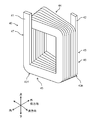
- FIG. 2 is a perspective view of the coil 40.
- FIG. 3A is a schematic cross-sectional view of a main part of the stator.
- FIG. 3B is a schematic cross-sectional view of a main part of the stator for comparison.
- the motor 1000 has a stator 100 and a rotor 200.
- the motor 1000 has components other than these, such as a motor case and bearings that support the output shaft. However, for convenience of explanation, the illustration and description thereof will be omitted.
- the stator 100 is provided between an annular yoke 20, a plurality of teeth 10 connected to the inner circumference of the yoke 20 and provided at equal intervals along the inner circumference, and teeth 10 adjacent to each other in the circumferential direction. It has a slot 30 and a coil 40 housed in the slot 30.
- the stator 100 is arranged on the outer side of the rotor 200 in the radial direction at regular intervals from the rotor 200.
- the teeth 10 and the yoke 20 are formed by, for example, laminating an electromagnetic steel sheet containing silicon or the like and then punching it.
- the coil 40 is a component in which a conducting wire made of copper or the like is spirally wound.
- the coil 40 is a molded coil formed by molding a conducting wire made of copper or the like having a quadrangular cross section.
- the coil 40 is attached to each of the plurality of teeth 10 with the insulator 50 (see FIG. 3A) interposed therebetween, and is housed in the slot 30.
- an insulating film is formed on the surface of the conducting wire constituting the coil 40. The details of the shape of the coil 40 will be described later.
- the "molded coil" in the present specification does not include a coil in which a conducting wire having a constant width and thickness is simply wound in a spiral shape.
- the forming coil is formed, for example, by preparing a plurality of rectangular plate materials having different lengths, widths or thicknesses, and joining these plate materials by cold pressure welding, welding, or other methods.
- the material of the plate material is a low resistance material such as copper and aluminum.
- the molding coil may be formed by so-called casting in which copper or the like is melted and poured into a mold.
- a forming coil may be formed by bending a plate-shaped conducting wire having a width or a thickness different in the middle at a predetermined position.
- a plate-shaped conductor having a constant width and thickness may be rolled at a predetermined portion, the width or thickness may be changed in the middle, and then spirally wound to form a forming coil.
- the forming coil is formed by adding another process other than winding the conductor, or by a method different from simply winding the conductor.
- the rotor 200 has an output shaft 210, a rotor core 220 having the output shaft 210 as an axis, and a plurality of magnets 230.
- the plurality of magnets 230 are embedded inside the rotor core 220, and the north and south poles are alternately arranged along the outer peripheral direction of the output shaft so as to face the stator 100.
- the material, shape, and material of the magnet 230 can be appropriately changed according to the output of the motor 1000 and the like.
- the rotor core 220 is formed by, for example, punching after laminating an electromagnetic steel sheet containing silicon or the like.
- Coil U1 to U4, V1 to V4, W1 to W4 are connected in series, respectively.
- Three phases of U, V, and W which have a phase difference of 120 ° in electrical angle from each other, are supplied to and excited by the coils U1 to U4, V1 to V4, and W1 to W4, respectively, and a rotating magnetic field is generated in the stator 100.
- An interaction occurs between this rotating magnetic field and the magnetic field generated by the magnet 230 provided in the rotor 200 to generate torque, and the output shaft 210 rotates while being supported by a bearing (not shown).
- the output shaft 210 can rotate in either the clockwise direction or the counterclockwise direction according to the phase difference of the three-phase currents of the U, V, and W phases.
- the rotation direction of the output shaft 210 is determined when viewed from the lower side in the axial direction.
- the coil 40 has a first lead portion 41, a second lead portion 42, and a winding portion 43.
- the conducting wire is spirally wound for a plurality of turns.
- the winding portion 43 has first to nth turns 431 to 43n.
- n is an integer of 2 or more.
- n 7.
- the present invention is not particularly limited to this, and this value can be appropriately changed according to the specifications of the motor 1000 and the like.
- the first to nth turns 431 to 43n are stacked in this order from the center side to the outer peripheral side of the motor 1000, and are housed in the slot 30.
- each of the first to nth turns 431 to 43n is a square ring having four sides when viewed in the radial direction.
- the winding portion 43 has a first side portion 44, a second side portion 45, a third side portion 46, and a fourth side portion 47 corresponding to this shape.
- Each side portion 44 to 47 includes a corresponding side portion of the first to nth turns 431 to 43n.
- the first side portion 44 corresponds to the upper end side portion in the axial direction of the four side portions.
- the second side portion 45 corresponds to the lower end side portion in the axial direction of the four side portions.
- the third side portion 46 corresponds to one end portion in the circumferential direction of the four side portions.
- the fourth side portion 47 corresponds to the other end portion in the circumferential direction of the four side portions.
- the first side portion 44 may be referred to as a first coil end 44
- the second side portion 45 may be referred to as a second coil end 45.
- the first lead portion 41 is continuous with the end portion of the first turn 431 and extends upward from the first coil end 44.
- the second lead portion 42 is continuous with the nth turn 43n and extends upward from the first coil end 44.
- the first lead portion 41 and the second lead portion 42 correspond to wiring portions and connection portions with the bus bar (not shown), and the insulating coating is removed from the respective tips. Further, the first lead portion 41 and the second lead portion 42 may be bent in the middle depending on the wiring, the connection position with the bus bar, and the like.
- the thicknesses of the first to nth turns 431 to 43n included in the third side portion 46 are the thicknesses of the first to nth included in the fourth side portion 47. It is thinner than the respective thicknesses of turns 431 to 43n.
- the insulator 50 is a tubular part with both ends open in the radial direction, and is made of an insulating material. By providing the insulator 50, it is possible to prevent a short circuit between the coil 40 and the teeth 10 and suppress a leakage current from the coil 40 to the teeth 10.
- the shape of the insulator 50 can be appropriately changed according to the shape of the teeth 10 and the yoke 20.
- the radial outer surface of the nth turn 43n abuts or approaches the inner circumference of the yoke 20.
- the coil 40 is arranged.
- the first to nth turns 431 to 43n included in the third side portion 46 are arranged so as to be in contact with adjacent turns in the radial direction. Therefore, the radial inner end face of the third side portion 46 recedes radially outward from the radial inner end face of the fourth side portion 47.
- the thicknesses of the third side portion 46 and the fourth side portion 47 are the same in the first to nth turns 431 to 43n. Therefore, the radial inner end surface of the third side portion 46 and the radial inner end surface of the fourth side portion 47 are located at substantially equidistant positions along the radial direction from the center of the motor 1000.
- the third side portion 46 is located on the lag side (hereinafter, simply referred to as the lag side) in the main rotation direction of the rotor 200.
- the fourth side portion 47 is located on the advancing side (hereinafter, simply referred to as the advancing side) of the rotor 200 in the main rotation direction.
- the direction of the magnetic flux generated by the current flowing through the coil 40 is the magnetic flux generated by the plurality of magnets 230 provided in the rotor 200 (hereinafter, hereinafter, It is simply different from the direction of the magnetic flux generated by the magnet 230). Therefore, on the advancing side, the magnetic flux generated by the magnet 230 and the magnetic flux generated by the coil 40 do not substantially interlink the coil 40.
- the direction of the magnetic flux generated by the current flowing through the coil 40 is the same as the direction of the magnetic flux generated by the magnet 230.
- the magnetic flux generated by the magnet 230 and the coil 40 interlinks the coil 40 on the delay side, and an eddy current loss occurs at this portion.
- the end face on the inner side in the radial direction of the third side portion 46 is retracted outward in the radial direction, the amount of magnetic flux interlinking the coil 40 on the lagging side is reduced. be able to. As a result, the eddy current loss can be reduced as compared with the example shown in FIG. 3B.
- the reach of the magnetic flux generated by the magnet 230 and the magnetic flux generated by the coil 40 is determined by the specifications of the magnet 230 and the shape of the tooth 10, and generally, as shown in FIGS. 3A and 3B, the rotor 200 Interlinks with coil 40 on the side closer to.
- the coil 40 according to the present embodiment is mounted on the stator 100 of the motor 1000.
- the motor 1000 has a stator 100, an output shaft 210 at the center of the shaft, and a plurality of magnets 230 on the outer peripheral side.
- the motor 1000 has at least a rotor 200 arranged radially inside the stator 100.
- the coil 40 includes a winding portion 43 composed of spirally wound first to nth turns 431 to 43n, a first lead portion 41 extending from the first turn 431, and a second lead portion 41 extending from the nth turn 43n. It has at least a lead portion 42 of the above.
- the shapes of the first to nth turns 431 to 43n are different between the lagging side and the advancing side in the main rotation direction of the rotor 200. Specifically, the thicknesses of the first to nth turns 431 to 43n included in the third side portion 46 located on the lagging side are included in the fourth side portion 47 located on the advancing side. It is thinner than the thickness of each of the 1st to nth turns 431 to 43n.
- the coil 40 By configuring the coil 40 in this way, it is possible to reduce the amount of magnetic flux in which the magnetic flux generated by the magnet 230 and the coil 40 interlinks the coil 40 when the motor 1000 rotates in the main rotation direction. This makes it possible to reduce the eddy current loss. Therefore, it is possible to suppress a decrease in the efficiency of the motor 1000.
- the resistance of the coil 40 increases, and the loss due to Joule heat (hereinafter referred to as copper loss) increases. Further, the space factor of the coil 40 in the slot 30 decreases. Due to these factors, there is a concern that the efficiency of the motor 1000 may be reduced.
- the present embodiment by making the shape of the coil 40 as described above, it is possible to suppress an increase in copper loss of the coil 40 and a decrease in the space factor of the coil 40 in the slot 30. This makes it possible to suppress a decrease in the efficiency of the motor 1000.
- the shapes of the coil 40 and the stator 100, particularly the insulator 50, are not limited to the examples shown in FIGS. 2 and 3A, and may have different shapes.
- FIG. 4 is a schematic cross-sectional view of a main part of another stator according to the first embodiment.
- the thickness of each of the first to nth turns 431 to 43n included in the third side portion 46 is the fourth side. It is thinner than the thickness of each of the first to nth turns 431 to 43n included in the portion 47.
- a plurality of groove portions 50a separated from each other in the radial direction are provided on the end face on the lagging side of the insulator 50 shown in FIG.
- Each of the first to nth turns 431 to 43n included in the third side portion 46 is housed in the groove portion 50a.
- the coil 40 and the stator 100 may be configured in this way. Also in this case, as compared with the configuration shown in FIG. 3B, the end face on the inner side in the radial direction of the third side portion 46 is retracted outward in the radial direction, so that the amount of magnetic flux interlinking the coil 40 on the lagging side is reduced. be able to. As a result, the eddy current loss can be reduced and the efficiency of the motor 1000 can be suppressed from being lowered.
- each groove portion 50a accommodates a part of the first to nth turns 431 to 43n. Therefore, as compared with the configuration shown in FIG. 3A, the amount of the radial inner end face of the third side portion 46 retracting radially outward is smaller.
- the first to nth turns 431 to 43n are arranged at intervals from each other on the lagging side, the amount of magnetic flux generated by the magnet 230 and the coil 40 interlinks the coil 40 is shown in FIG. 3A. It does not increase so much compared to the configuration shown in.
- an insulating spacer or an insulating paper is sandwiched between each of the first to nth turns 431 to 43n included in the third side portion 46. You may.
- the motor 1000 includes at least a rotor 200 having an output shaft 210 as an axis, and a stator 100 provided at a predetermined distance from the rotor 200 on the radial outer side of the rotor 200.
- the stator 100 has at least an annular yoke 20, a plurality of teeth 10 connected to the inner circumference of the yoke 20, and a plurality of coils 40 attached to each of the plurality of teeth 10.
- the amount of magnetic flux interlinking the coil 40 on the lagging side is reduced. Therefore, the eddy current loss can be reduced and the efficiency of the motor 1000 can be suppressed from being lowered.
- the motor 1000 rotates mainly in only one direction or in both the clockwise and counterclockwise directions depends on the specifications of the motor 1000. However, as typified by the main motor of an electric vehicle, there are many cases where the motor is mainly used by rotating in only one direction. By applying the motor 1000 as such a motor, the degree of reduction of the eddy current loss is increased, and the decrease in the efficiency of the motor 1000 can be suppressed more reliably.
- the coil 40 is mounted on the teeth 10 in a state of being wound in a single layer. By doing so, the structure of the coil 40 can be simplified, and an increase in the manufacturing cost of the coil 40 can be suppressed. Further, it becomes easy to design the total number of turns of the coil 40 wound around the teeth 10. However, the coil 40 may be mounted on the teeth 10 in a state of being wound in multiple layers.
- the shapes of the first to nth turns 431 to 43n of the coil 40 may be different between the lagging side and the leading side.
- the volume of the first to nth turns 431 to 43n located on the lagging side may be smaller than the volume of the first to nth turns 431 to 43n located on the advancing side.
- this relationship may be established on the side closer to the rotor 200.
- the coil 40 of the present embodiment is the coil 40 mounted on the stator of the motor 1000, and the motor 1000 has the stator 100, the output shaft 210 at the axis, and a plurality of magnets 230 on the outer peripheral side.
- the coil 40 has first to nth (n is an integer of 2 or more) turns 431 wound in a spiral shape, and has at least a rotor 200 arranged inside the stator 100 in the radial direction. It has at least a winding portion 43 composed of ⁇ 43n, a first lead portion 41 extending from the first turn 431, and a second lead portion 42 extending from the nth turn 43n, and has at least the first to nth turns 431.
- the shape of a part or all of ⁇ 43n is different from the other parts in the portion where the magnetic flux generated by the magnet 230 or the coil 40 is interlinked with the coil 40.
- the shape of a part or all of the first to nth turns 431 to 43n may be different between the lagging side and the advancing side in the main rotation direction of the rotor 200.
- the thickness of each of some or all turns is the advancing side in the main rotation direction of the rotor 200. It may be thinner than the respective thicknesses of the first to nth turns 431 to 43n located in.
- the motor 1000 of the present embodiment is provided with a rotor 200 having an output shaft 210 at the axis and a plurality of magnets 230 on the outer peripheral side, respectively, and a rotor 200 on the radial outer side of the rotor 200 at a predetermined distance.
- the stator 100 includes at least an annular yoke 20, a plurality of teeth 10 connected to the inner circumference of the yoke 20, and a plurality of coils 40 mounted on each of the plurality of teeth 10.
- Each of the plurality of coils 40 is the coil 40 according to any one of the first and second embodiments and the first to sixth modifications.
- the coil 40 may be mounted on the teeth 10 in a state of being wound in a single layer.
- the shape of the coil 40 is not limited to the shape shown in the present embodiment, and various shapes can be taken. Hereinafter, variations in the shape of the coil 40 will be described with reference to modifications.
- FIG. 5 is a schematic cross-sectional view of a main part of the stator according to the first modification.
- FIG. 6 is a schematic cross-sectional view of a main part of another stator according to the first modification.
- FIGS. 5, 6 and the drawings shown thereafter the same parts as those in the first embodiment are designated by the same reference numerals, and detailed description thereof will be omitted.
- the thickness of the turn on the side closer to the rotor 200 is the thickness. It differs from the configuration shown in the first embodiment in that it is thinner than the other turns. In this modification, on the lagging side, the thickness of only two turns including the nth turn 43n is thinner than that of the other turns. However, it is not particularly limited to this. It can be appropriately changed according to the specifications of the motor 1000 and the request for the degree of decrease in the amount of interlinkage magnetic flux.
- the amount of magnetic flux generated by the magnet 230 and the coil 40 reduces the amount of magnetic flux interlinking the coil 40. Can be done. As a result, the eddy current loss can be reduced and the efficiency of the motor 1000 can be suppressed from being lowered.
- the number of turns for reducing the thickness can be reduced in the third side portion 46. As a result, it is possible to further suppress an increase in copper loss of the coil 40. Further, it is possible to suppress a decrease in the space factor of the coil 40 in the slot 30. As a result, the decrease in efficiency of the motor 1000 can be further suppressed.
- the groove portion 50a may be arranged according to the position and number of turns whose thickness has been reduced. By doing so, it is possible to obtain the same effect as that of the configuration shown in FIG.
- the thickness is reduced. Insulating spacers or insulating paper may be sandwiched.
- the coil 40 of the present modification has a thickness of one or a plurality of turns close to the rotor 200 among the first to nth turns 431 to 43n located on the lagging side in the main rotation direction of the rotor 200. , Thinner than the thickness of other turns.
- FIG. 7 is a schematic cross-sectional view of a main part of the stator according to the second modification.
- FIG. 8 is a schematic cross-sectional view of a main part of another stator according to the second modification.
- the configuration of the present modification shown in FIG. 7 is the width of the k-th turn (k is an integer, 1 ⁇ k ⁇ n) included in the third side portion 46 located on the lagging side, in this case, the width in the circumferential direction. However, it is different from the configuration shown in the first embodiment in that it is narrower than the width of the k-th turn included in the fourth side portion 47 located on the advancing side.
- the thickness of the insulator 51 is different from that of the insulator 50 shown in the first embodiment in that the thickness of the insulator 51 is thicker on the lagging side than on the advancing side.
- the shape of the coil 40 may be defined as shown in this modification. Also in this case, since the volume of the first to nth turns 431 to 43n located on the lagging side is smaller than the volume of the first to nth turns 431 to 43n located on the advancing side, the configuration shown in the first embodiment is shown. Can produce the same effect as.
- the gap in the slot 30 can be filled and the stator 100 can be stabilized.
- the kth turn having a narrow width may be arranged only on the side of the first to nth turns 431 to 43n that is closer to the rotor 200. Good.
- the nth turn 43n and the (n-1) turn correspond to the kth turn.
- it is not particularly limited to this. It can be appropriately changed according to the specifications of the motor 1000, the request for the degree of decrease in the amount of interlinkage magnetic flux, and the like.
- the amount of magnetic flux generated by the magnet 230 and the coil 40 can reduce the amount of magnetic flux interlinking the coil 40.
- the eddy current loss can be reduced and the efficiency of the motor 1000 can be suppressed from being lowered.
- the number of turns in which the width is narrowed from the predetermined value can be reduced in the third side portion 46.
- the thickness of the insulator 51 may be changed along the radial direction according to the position and number of turns whose width is narrowed from a predetermined value.
- the width of the kth turn (k is an integer and 1 ⁇ k ⁇ n) located on the lagging side of the main rotation direction of the rotor 200 is the main rotation direction of the rotor 200. It is narrower than the width of the turn corresponding to the kth turn located on the advancing side of.
- the kth turn may be located on the side closer to the rotor 200 in the first to nth turns 431 to 43n.
- FIG. 9 is a side view of the coil according to the modified example 3.
- FIG. 10 is a partial schematic view of the third side portion and the fourth side portion. Note that FIG. 9 is a side view of the coil 40 as viewed from the inside in the radial direction.
- the configuration of the present modification shown in FIGS. 9 and 10 is an embodiment in which a first concave portion 46a showing a concave shape when the coil 40 is viewed in the radial direction is formed on the third side portion 46. It is different from the configuration shown in 1.
- the coil 40 of this modified example shown in FIGS. 9 and 10 has the third side portion 46 and the fourth side portion 47, and the first to nth turns 431, similarly to the coil 40 shown in FIG. 3B.
- the thickness of each of ⁇ 43n is equal.
- the widths of the first to nth turns 431 to 43n included in the third side portion 46 are equal to the widths of the first to nth turns 431 to 43n included in the fourth side portion 47.
- the third side portion 46 a portion where the magnetic flux generated by the magnet 230 and the coil 40 intersect is simulated in advance, and the first recess 46a is formed in that portion. it can.
- the volume of the coil 40 can be increased as compared with the configurations shown in the first embodiment and the first and second modifications. That is, since the copper loss is further reduced, the efficiency of the motor 1000 can be maintained high.
- a second recess 47a may be formed on the fourth side portion 47. However, it is necessary to establish any of the following relationships between the first recess 46a and the second recess 47a.
- the size of the first recess 46a is larger than the size of the second recess 47a.
- the axial width A1 of the first recess 46a is wider than the axial width A2 of the second recess 47a (A1> A2).
- the circumferential depth B1 of the first recess 46a is deeper than the circumferential depth B2 of the second recess 47a (B1> B2).
- the total volume of the first recess 46a formed in the third side portion 46 may be larger than the total volume of the second recess 47a formed in the fourth side portion 47.
- the magnetic flux generated by the magnet 230 and the coil 40 may be interlinked with the fourth side portion 47.
- the coil of the portion where the magnetic flux generated by the magnet 230 and the coil 40 is interlinked even on the advancing side.
- the volume of 40 can be reduced to reduce the eddy current loss.
- the copper loss is increased while reducing the eddy current loss on the lagging side where the amount of interlinkage magnetic flux is large. Can be suppressed. As a result, the efficiency of the motor 1000 can be maintained high.
- the first recess 46a does not have to be formed on the entire first to nth turns 431 to 43n of the third side portion 46. For example, it may be provided in the first to kth turns on the side closer to the rotor 200. The same applies to the second recess 47a.
- FIG. 9 shows an example in which the second recess 47a is formed on the fourth side portion 47, but if the amount of interlinkage magnetic flux on the fourth side portion 47 is small, the formation of the second recess 47a is omitted. You may.
- the positions, numbers, and sizes of the first recess 46a and the second recess 47a can be appropriately changed according to the region where the magnetic flux generated by the magnet 230 and the coil 40 interlinks with the coil 40.
- the coil 40 of the present modification has at least one or more first recesses 46a in a part or all of the first to nth turns 431 to 43n located on the lagging side in the main rotation direction of the rotor 200. Is formed.
- At least one or more second recesses 47a are formed in a part or all of the first to nth turns 431 to 43n located on the advancing side in the main rotation direction of the rotor, and the entire first recesses 46a are formed. Is preferably larger than the total volume of the second recess 47a.
- FIG. 11 is a side view of the coil according to the modified example 4.
- FIG. 12 is a partial schematic view of the third side portion and the fourth side portion. Note that FIG. 11 is a side view of the coil 40 as viewed from the inside in the radial direction.
- the configuration of the present modification shown in FIGS. 11 and 12 is different from the configuration shown in the modification 3 in that the first slit 46b penetrating the coil 40 is formed on the third side portion 46.
- the same effect as that of the configuration shown in the modified example 3 can be obtained. That is, on the delay side, the volume of the coil 40 at the portion where the magnetic fluxes generated by the magnet 230 and the coil 40 intersect can be reduced to reduce the eddy current loss. As a result, it is possible to suppress a decrease in the efficiency of the motor 1000. Moreover, the volume reduction of the coil 40 can be suppressed. Therefore, the copper loss is further reduced, and the efficiency of the motor 1000 can be maintained high.
- the second slit 47b may be formed on the fourth side portion 47. However, it is necessary to establish any of the following relationships between the first slit 46b and the second slit 47b.
- the size of the first slit 46b is larger than the size of the second slit 47b.
- the axial width A3 of the first slit 46b is wider than the axial width A4 of the second slit 47b (A3> A4).
- the circumferential width B3 of the first slit 46b is wider than the circumferential width B4 of the second slit 47b (B3> B4).
- the total volume of the first slit 46b formed on the third side portion 46 may be larger than the total volume of the second slit 47b formed on the fourth side portion 47.
- the first slit 46b does not have to be formed on the entire first to nth turns 431 to 43n of the third side portion 46. For example, it may be provided in the first to kth turns on the side closer to the rotor 200. The same applies to the second slit 47b.
- FIG. 12 an example in which the second slit 47b is formed on the fourth side portion 47 is shown, but if the amount of interlinkage magnetic flux on the fourth side portion 47 is small, as shown in FIG. The formation of the second slit 47b may be omitted.
- the positions, numbers, and sizes of the first slit 46b and the second slit 47b can be appropriately changed according to the region where the magnetic flux generated by the magnet 230 and the coil 40 interlinks with the coil 40.
- the coil 40 of the present modification has at least one or more first slits 46b in a part or all of the first to nth turns 431 to 43n located on the lagging side in the main rotation direction of the rotor 200. Is formed.
- At least one or more second slits 47b are formed in a part or all of the first to nth turns 431 to 43n located on the advancing side in the main rotation direction of the rotor 200, and the first slit 46b It is preferable that the total volume is larger than the total volume of the second slit 47b.
- FIG. 13 is a schematic view of a main part of the motor according to the second embodiment of the present invention as viewed from the radial direction.
- FIG. 14 is a perspective view of the coil.
- the upper surface of the rotor core 220 and the upper surfaces of the teeth 10 and the yoke 20 are at substantially the same height in the axial direction.
- the lower surface of the rotor core 220 and the lower surfaces of the teeth 10 and the yoke 20 are at substantially the same height.
- the rotor core 220 may be designed to be higher than the stator 100 in the axial direction. By doing so, a larger amount of magnetic flux generated by the magnet 230 can be passed through the teeth 10 and the yoke 20, and the rotational torque of the output shaft 210 can be increased. Further, in such a structure, the magnetic flux generated by the magnet 230 also flows to the outside of the stator 100. Therefore, by arranging a magnetic sensor (not shown) in the vicinity of the rotor 200, the magnetic field inside the motor 1000 can be easily detected. can do.
- the magnetic flux generated by the magnet 230 invades from the upper side in the axial direction and interlinks with the first coil end 44. Therefore, the eddy current loss in this portion increases, and the efficiency of the motor 1000 may decrease.
- the configurations shown in the first embodiment and the modified examples 1 to 4 are modified and applied. As a result, it is possible to reduce the eddy current loss generated at the first coil end 44 and suppress the decrease in efficiency of the motor 1000.
- the thicknesses of the first to nth turns 431 to 43n included in the first coil end 44 are the thicknesses of the first to nth turns 431 included in the second coil end 45. It is thinner than each thickness of ⁇ 43n.
- the volume of the first coil end 44 can be reduced, the eddy current loss can be reduced, and the efficiency decrease of the motor 1000 can be suppressed.
- the coil 40 disclosed in the present specification has the following configurations.
- the coil 40 is mounted on the stator 100 of the motor 1000.
- the motor 1000 has at least a stator 100, an output shaft 210 at the center of the shaft, a plurality of magnets 230 on the outer peripheral side, and a rotor 200 arranged radially inside the stator 100.
- the coil 40 includes a winding portion 43 composed of spirally wound first to nth turns 431 to 43n, a first lead portion 41 extending from the first turn 431, and a second lead portion 41 extending from the nth turn 43n. It has at least a lead portion 42 of the above.
- the shape of a part or all of the first to nth turns 431 to 43n is different from the other parts in the portion where the magnetic flux generated by the magnet 230 interlinks with the coil 40.
- the volume of the first to nth turns 431 to 43n is smaller than the volume of the other portion.
- the winding portion 43 has a first coil end 44 located on one side of the axial direction of the motor 1000 and a second coil end 44 located on the other side of the axial direction. It has two coil ends 45, and includes first to nth turns 431 to 43n included in the first coil end 44 and first to nth turns 431 to 43n included in the second coil end 45. And, some or all of the shapes are different.
- the thickness of each of a part of the turns or all the turns is included in the second coil end 45 from the first to the first to 43n. It is preferably thinner than the respective thicknesses of the nth turns 431 to 43n.
- FIG. 15 is a side view of the coil according to the modified example 5.
- FIG. 16 is a partial schematic view of the first coil end and the second coil end. Note that FIG. 15 is a side view of the coil 40 as viewed from the inside in the radial direction.
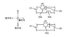
- the configuration of the present modification shown in FIGS. 15 and 16 is the embodiment in that the first coil end 44 is formed with a third concave portion 44a showing a concave shape when the coil 40 is viewed in the radial direction. It is different from the configurations shown in 1 and 2 and the modified example 3.
- the thickness of each of the first coil end 44 and the second coil end 45 is the same for the first to nth turns 431 to 43n.
- the volume of the portion where the magnetic flux generated by the magnet 230 intersects can be reduced, and the eddy current loss can be reduced. As a result, it is possible to suppress a decrease in the efficiency of the motor 1000.
- a portion where the magnetic flux generated by the magnet 230 intersects can be simulated in advance, and a third recess 44a can be formed in that portion.
- the volume of the coil 40 can be increased as compared with the configuration shown in the second embodiment. That is, the copper loss is further reduced. Therefore, the efficiency of the motor 1000 can be maintained high.
- a fourth recess 45a may be formed at the second coil end 45. However, it is necessary to establish any of the following relationships between the third recess 44a and the fourth recess 45a.
- the size of the third recess 44a is larger than the size of the fourth recess 45a.
- the circumferential width A5 of the third recess 44a is wider than the circumferential width A6 of the fourth recess 45a (A5> A6).
- the axial depth B5 of the third recess 44a is deeper than the axial depth B6 of the fourth recess 45a (B5> B6).
- the total volume of the third recess 44a formed in the first coil end 44 may be larger than the total volume of the fourth recess 45a formed in the second coil end 45.
- the magnetic flux generated by the magnet 230 may interlink with the second coil end 45.
- the second coil end 45 may be provided with the fourth recess 45a.
- the third recess 44a does not have to be formed in the entire first to nth turns 431 to 43n of the first coil end 44.
- it may be provided in the first to kth (k is a natural number smaller than n) turns on the side closer to the rotor 200.
- FIG. 15 shows an example in which a fourth recess 45a is formed in the second coil end 45.
- the formation of the fourth recess 45a may be omitted.
- the positions, numbers, and sizes of the third recess 44a and the fourth recess 45a can be appropriately changed according to the region where the magnetic flux generated by the magnet 230 interlinks with the coil 40.
- At least one or more third recesses 44a are formed in a part or all of the first to nth turns 431 to 43n included in the first coil end 44. ing.
- At least one or more fourth recesses 45a are formed in a part or all of the first to nth turns 431 to 43n included in the second coil end 45, and the total volume of the third recess 44a is formed. However, it is preferable that the volume is larger than the total volume of the fourth recess 45a.
- FIG. 17 is a side view of the coil according to the modified example 6.
- FIG. 18 is a partial schematic view of the first coil end and the second coil end.
- FIG. 11 is a side view of the coil 40 as viewed from the inside in the radial direction.
- the configuration of the present modification shown in FIGS. 17 and 18 is different from the configuration shown in the modification 5 in that the third slit 44b is formed in the first coil end 44.
- the same effect as that of the configuration shown in the modified example 4 can be obtained.
- the volume of the portion where the magnetic flux generated by the magnet 230 intersects can be reduced to reduce the eddy current loss.
- copper loss can be reduced. As a result, it is possible to suppress a decrease in the efficiency of the motor 1000.
- a fourth slit 45b may be formed at the second coil end 45. However, it is necessary to establish any of the following relationships between the third slit 44b and the fourth slit 45b.
- the size of the third slit 44b is larger than the size of the fourth slit 45b.
- the axial width A7 of the third slit 44b is wider than the axial width A8 of the fourth slit 45b (A7> A8).
- the circumferential width B7 of the third slit 44b is wider than the circumferential width B8 of the fourth slit 45b (B7> B8).
- the total volume of the third slit 44b formed in the first coil end 44 may be larger than the total volume of the fourth slit 45b formed in the second coil end 45.
- the volume of the portion where the magnetic flux generated by the magnet 230 intersects can be reduced, and the eddy current loss can be reduced.
- the increase in copper loss can be suppressed.
- the efficiency of the motor 1000 can be maintained high.
- the third slit 44b does not have to be formed on the entire first to nth turns 431 to 43n of the first coil end 44. For example, it may be provided in the first to kth turns on the side closer to the rotor 200. The same applies to the fourth slit 45b.
- FIG. 18 shows an example in which the fourth slit 45b is formed in the second coil end 45, but if the amount of interlinkage magnetic flux at the second coil end 45 is small, as shown in FIG. The formation of the fourth slit 45b may be omitted.
- the positions, numbers, and sizes of the third slit 44b and the fourth slit 45b can be appropriately changed according to the region where the magnetic flux generated by the magnet 230 interlinks with the coil 40.
- At least one or more third slits 44b are formed in a part or all of the first to nth turns 431 to 43n included in the first coil end 44. ing.
- At least one or more fourth slits 45b are formed in a part or all of the first to nth turns 431 to 43n included in the second coil end 45, and the total volume of the third slit 44b is formed. However, it is preferable that the volume is larger than the total volume of the fourth slit 45b.
- the third recess 44a may be provided in the first coil end 44.
- a fourth recess 45a may be provided in the second coil end 45.
- the example in which the magnetic flux generated by the magnet 230 interlinks with the first coil end 44 is shown, but depending on the structure of the motor 1000, the magnetic flux generated by the magnet 230 is the second. It may be interlinked with the coil end 45 of. In such a case, it is advisable to apply the deformation applied to the first coil end 44 to the second coil end 45. For example, make the thickness of each of the first to nth turns 43n included in the second coil end 45 thinner than the thickness of each of the first to nth turns 43n included in the first coil end 44. To.
- the total volume of the fourth recess 45a formed in the second coil end 45 is made larger than the total volume of the third recess 44a formed in the first coil end 44.
- the total volume of the fourth slit 45b formed in the second coil end 45 is made larger than the total volume of the third slit 44b formed in the first coil end 44.
- the eddy current loss at the portion where the magnetic flux generated by the magnet 230 is linked to the coil 40 can be reliably reduced.
- the cross-sectional shape of the conducting wire constituting the coil 40 is not particularly limited to a quadrangle, and may be another shape. For example, it may be an m-square (m is an integer of 3 or more). It may also be oval.
- the coil of the present invention can reduce eddy current loss caused by magnets and coils provided in the rotor. Therefore, it is useful for applying to a motor that requires high efficiency.
- Teeth 20 Yoke 30 Slot 40 Coil 41 First lead portion 42 Second lead portion 43 Winding portions 431 to 43n First to n turns 44 First coil end (first side portion) 44a Third recess 44b Third slit 45 Second coil end (second side) 45a 4th recess 45b 4th slit 46 3rd side (delayed side) 46a 1st recess 46b 1st slit 47 4th side (advancing side) 47a Second recess 47b Second slit 50, 51 Insulator 50a Groove 100 Stator 200 Rotor 210 Output shaft 220 Rotor core 230 Magnet 1000 Motor
Landscapes
- Engineering & Computer Science (AREA)
- Power Engineering (AREA)
- Windings For Motors And Generators (AREA)
- Iron Core Of Rotating Electric Machines (AREA)
Priority Applications (1)
| Application Number | Priority Date | Filing Date | Title |
|---|---|---|---|
| JP2021563759A JP7599070B2 (ja) | 2019-12-12 | 2020-10-01 | コイル及びそれを備えたモータ |
Applications Claiming Priority (2)
| Application Number | Priority Date | Filing Date | Title |
|---|---|---|---|
| JP2019-224773 | 2019-12-12 | ||
| JP2019224773 | 2019-12-12 |
Publications (1)
| Publication Number | Publication Date |
|---|---|
| WO2021117320A1 true WO2021117320A1 (ja) | 2021-06-17 |
Family
ID=76329366
Family Applications (1)
| Application Number | Title | Priority Date | Filing Date |
|---|---|---|---|
| PCT/JP2020/037389 Ceased WO2021117320A1 (ja) | 2019-12-12 | 2020-10-01 | コイル及びそれを備えたモータ |
Country Status (2)
| Country | Link |
|---|---|
| JP (1) | JP7599070B2 (https=) |
| WO (1) | WO2021117320A1 (https=) |
Cited By (1)
| Publication number | Priority date | Publication date | Assignee | Title |
|---|---|---|---|---|
| WO2024154677A1 (ja) * | 2023-01-17 | 2024-07-25 | パナソニックIpマネジメント株式会社 | モータ |
Citations (6)
| Publication number | Priority date | Publication date | Assignee | Title |
|---|---|---|---|---|
| JP2006014530A (ja) * | 2004-06-28 | 2006-01-12 | Sumitomo Electric Ind Ltd | コイルとその製造方法 |
| JP2008167593A (ja) * | 2006-12-28 | 2008-07-17 | Toyota Motor Corp | モータの固定子及びモータのコイル製造方法 |
| JP2012186938A (ja) * | 2011-03-07 | 2012-09-27 | Denso Corp | 電機子 |
| JP5805046B2 (ja) * | 2012-10-15 | 2015-11-04 | 三菱電機株式会社 | 車両用電動機および車両用発電機 |
| JP2018117480A (ja) * | 2017-01-20 | 2018-07-26 | アイシン・エィ・ダブリュ株式会社 | コイル、ステータおよびコイルの製造方法 |
| WO2019203076A1 (ja) * | 2018-04-18 | 2019-10-24 | パナソニックIpマネジメント株式会社 | コイル及びそれを用いたモータ |
-
2020
- 2020-10-01 WO PCT/JP2020/037389 patent/WO2021117320A1/ja not_active Ceased
- 2020-10-01 JP JP2021563759A patent/JP7599070B2/ja active Active
Patent Citations (6)
| Publication number | Priority date | Publication date | Assignee | Title |
|---|---|---|---|---|
| JP2006014530A (ja) * | 2004-06-28 | 2006-01-12 | Sumitomo Electric Ind Ltd | コイルとその製造方法 |
| JP2008167593A (ja) * | 2006-12-28 | 2008-07-17 | Toyota Motor Corp | モータの固定子及びモータのコイル製造方法 |
| JP2012186938A (ja) * | 2011-03-07 | 2012-09-27 | Denso Corp | 電機子 |
| JP5805046B2 (ja) * | 2012-10-15 | 2015-11-04 | 三菱電機株式会社 | 車両用電動機および車両用発電機 |
| JP2018117480A (ja) * | 2017-01-20 | 2018-07-26 | アイシン・エィ・ダブリュ株式会社 | コイル、ステータおよびコイルの製造方法 |
| WO2019203076A1 (ja) * | 2018-04-18 | 2019-10-24 | パナソニックIpマネジメント株式会社 | コイル及びそれを用いたモータ |
Cited By (1)
| Publication number | Priority date | Publication date | Assignee | Title |
|---|---|---|---|---|
| WO2024154677A1 (ja) * | 2023-01-17 | 2024-07-25 | パナソニックIpマネジメント株式会社 | モータ |
Also Published As
| Publication number | Publication date |
|---|---|
| JP7599070B2 (ja) | 2024-12-13 |
| JPWO2021117320A1 (https=) | 2021-06-17 |
Similar Documents
| Publication | Publication Date | Title |
|---|---|---|
| US7977826B2 (en) | Multipole permanent-magnet synchronous machine having tooth-wound coils | |
| JP3971692B2 (ja) | スロットレス永久磁石式回転電機及びその巻線製造方法 | |
| KR101255960B1 (ko) | 스위치드 릴럭턴스 모터 | |
| US6236135B1 (en) | Toroidal core type actuator with phase separator | |
| JP2014072988A (ja) | 固定子コア、分割コアブロック、固定子の製造方法、および回転電機 | |
| JP5619046B2 (ja) | 回転電機およびそれに用いられるステータの製造方法 | |
| WO2009084473A1 (ja) | ステータ及びこれを用いた回転電機 | |
| US20120086288A1 (en) | Electric rotating machine | |
| JP5325785B2 (ja) | 回転電気機械のためのステータ | |
| TWI345352B (https=) | ||
| WO2014102950A1 (ja) | 回転電機 | |
| WO2018066654A1 (ja) | 同期リラクタンス型回転電機 | |
| US10312776B2 (en) | Synchronous motor with permanent magnets | |
| JP4735210B2 (ja) | モータ | |
| JP2012095488A (ja) | 回転電機用ロータ、およびこれを用いた回転電機 | |
| WO2021131575A1 (ja) | コイル及びそれを備えたステータ、モータ | |
| JP6210705B2 (ja) | 回転電機およびそれに用いられる固定子 | |
| JP2014207785A (ja) | モータ | |
| JP5239571B2 (ja) | 回転電機 | |
| WO2021117320A1 (ja) | コイル及びそれを備えたモータ | |
| JPWO2021117320A5 (https=) | ||
| JP2005124378A (ja) | リング状の固定子コイルを有する誘導電動機 | |
| JP6747834B2 (ja) | ステータ | |
| WO2003096519A2 (fr) | Moteur a induction dont les enroulements de stator sont divises axialement | |
| JP7172809B2 (ja) | 回転電機 |
Legal Events
| Date | Code | Title | Description |
|---|---|---|---|
| 121 | Ep: the epo has been informed by wipo that ep was designated in this application |
Ref document number: 20897845 Country of ref document: EP Kind code of ref document: A1 |
|
| ENP | Entry into the national phase |
Ref document number: 2021563759 Country of ref document: JP Kind code of ref document: A |
|
| NENP | Non-entry into the national phase |
Ref country code: DE |
|
| 122 | Ep: pct application non-entry in european phase |
Ref document number: 20897845 Country of ref document: EP Kind code of ref document: A1 |