WO2021117234A1 - モデル共有システム、モデル管理装置、および空気調和装置の制御装置 - Google Patents
モデル共有システム、モデル管理装置、および空気調和装置の制御装置 Download PDFInfo
- Publication number
- WO2021117234A1 WO2021117234A1 PCT/JP2019/048993 JP2019048993W WO2021117234A1 WO 2021117234 A1 WO2021117234 A1 WO 2021117234A1 JP 2019048993 W JP2019048993 W JP 2019048993W WO 2021117234 A1 WO2021117234 A1 WO 2021117234A1
- Authority
- WO
- WIPO (PCT)
- Prior art keywords
- model
- air conditioner
- heat load
- operating state
- management device
- Prior art date
- Legal status (The legal status is an assumption and is not a legal conclusion. Google has not performed a legal analysis and makes no representation as to the accuracy of the status listed.)
- Ceased
Links
Images


Classifications
-
- F—MECHANICAL ENGINEERING; LIGHTING; HEATING; WEAPONS; BLASTING
- F24—HEATING; RANGES; VENTILATING
- F24F—AIR-CONDITIONING; AIR-HUMIDIFICATION; VENTILATION; USE OF AIR CURRENTS FOR SCREENING
- F24F11/00—Control or safety arrangements
- F24F11/62—Control or safety arrangements characterised by the type of control or by internal processing, e.g. using fuzzy logic, adaptive control or estimation of values
- F24F11/63—Electronic processing
-
- F—MECHANICAL ENGINEERING; LIGHTING; HEATING; WEAPONS; BLASTING
- F24—HEATING; RANGES; VENTILATING
- F24F—AIR-CONDITIONING; AIR-HUMIDIFICATION; VENTILATION; USE OF AIR CURRENTS FOR SCREENING
- F24F11/00—Control or safety arrangements
- F24F11/30—Control or safety arrangements for purposes related to the operation of the system, e.g. for safety or monitoring
-
- G—PHYSICS
- G05—CONTROLLING; REGULATING
- G05B—CONTROL OR REGULATING SYSTEMS IN GENERAL; FUNCTIONAL ELEMENTS OF SUCH SYSTEMS; MONITORING OR TESTING ARRANGEMENTS FOR SUCH SYSTEMS OR ELEMENTS
- G05B19/00—Program-control systems
- G05B19/02—Program-control systems electric
- G05B19/04—Program control other than numerical control, i.e. in sequence controllers or logic controllers
- G05B19/042—Program control other than numerical control, i.e. in sequence controllers or logic controllers using digital processors
-
- F—MECHANICAL ENGINEERING; LIGHTING; HEATING; WEAPONS; BLASTING
- F24—HEATING; RANGES; VENTILATING
- F24F—AIR-CONDITIONING; AIR-HUMIDIFICATION; VENTILATION; USE OF AIR CURRENTS FOR SCREENING
- F24F2110/00—Control inputs relating to air properties
- F24F2110/10—Temperature
-
- F—MECHANICAL ENGINEERING; LIGHTING; HEATING; WEAPONS; BLASTING
- F24—HEATING; RANGES; VENTILATING
- F24F—AIR-CONDITIONING; AIR-HUMIDIFICATION; VENTILATION; USE OF AIR CURRENTS FOR SCREENING
- F24F2110/00—Control inputs relating to air properties
- F24F2110/10—Temperature
- F24F2110/12—Temperature of the outside air
-
- F—MECHANICAL ENGINEERING; LIGHTING; HEATING; WEAPONS; BLASTING
- F24—HEATING; RANGES; VENTILATING
- F24F—AIR-CONDITIONING; AIR-HUMIDIFICATION; VENTILATION; USE OF AIR CURRENTS FOR SCREENING
- F24F2140/00—Control inputs relating to system states
-
- G—PHYSICS
- G05—CONTROLLING; REGULATING
- G05B—CONTROL OR REGULATING SYSTEMS IN GENERAL; FUNCTIONAL ELEMENTS OF SUCH SYSTEMS; MONITORING OR TESTING ARRANGEMENTS FOR SUCH SYSTEMS OR ELEMENTS
- G05B2219/00—Program-control systems
- G05B2219/20—Pc systems
- G05B2219/26—Pc applications
- G05B2219/2614—HVAC, heating, ventillation, climate control
Definitions
- This disclosure relates to a model sharing system, a model management device, and a control device for an air conditioner.
- a method of performing high-precision control by using machine learning is known.
- a model consisting of a control program and control parameters is generated by learning using the past operation history.
- the plurality of robot control devices described in Patent Document 1 reduce the time required for learning by sharing the trained model.
- an object of the present disclosure is a model sharing system, a model management device, and a model management device capable of performing highly accurate control even when there is a large difference in the control contents of the controlled device depending on the operating state of the controlled device. It is to provide a control system for an air conditioning system.
- Each of the model sharing systems of the present disclosure includes a plurality of control devices that control the corresponding controlled devices, and a model management device that stores the learned model according to the operating state of the controlled devices.
- the control device acquires a trained model corresponding to the operating state that is the same as or similar to the operating state of the corresponding controlled device from the model management device, and uses the acquired trained model to obtain the corresponding controlled device.
- Control includes at least one of the type of controlled device, the environment in which the controlled device is installed, and the setting of the controlled device.
- the present disclosure is a model management device of a model sharing system that shares a plurality of learned heat load models among control devices of a plurality of air conditioners.
- the model management device includes a model storage unit that stores each of a plurality of learned heat load models according to the operating state of the air conditioner, a communication unit that can communicate with the control devices of the plurality of air conditioners, and air. Operation of the air conditioner among a plurality of learned heat load models stored in the model storage unit in response to a transmission request of the heat load model that specifies the operating state of the air conditioner from the control device of the air conditioner.
- a model provider that provides the control device of the air conditioner with a heat load model that corresponds to the operating state that is the same as or has the same degree of similarity to the state, and a learned heat load that specifies the operating state of the air conditioner from the air conditioner. It is provided with a model registration unit that acquires a model and stores the acquired learned heat load model corresponding to the operating state of the acquired air conditioner in the model storage unit.
- the control device of the air conditioner of the present disclosure includes a communication unit capable of communicating with a model management device that manages a learned heat load model shared among the control devices of a plurality of air conditioners.
- the model management device stores the trained heat load model corresponding to the operating state of the air conditioner.
- the control device of the air conditioner of the present disclosure further issues a transmission request for a heat load model that specifies the operating state of the air conditioner, and the trained heat load transmitted from the model management device in response to the transmission request. It includes a control unit that acquires a model.
- the trained thermal load model corresponds to the operating condition that is the same as or has the greatest similarity to the specified operating condition.
- the control device of the air conditioner of the present disclosure further acquires the input data and the teacher data of the heat load model for additional learning by operating the air conditioner, and uses the acquired input data and the teacher data. It also has a learning unit for additional learning of the acquired heat load model.
- the control unit controls the air conditioner using the heat load model that has been additionally learned.
- the communication unit transmits the additionally learned heat load model to the model management device together with the operating state of the air conditioner.
- the operating condition includes at least one of the type of air conditioner, the environment in which the air conditioner is installed, and the setting of the air conditioner.
- the control device acquires a trained model corresponding to the same or similar operating state as the operating state of the corresponding controlled device from the model management device, and uses the acquired trained model. Control the corresponding controlled device. As a result, high-precision control can be executed even when there is a large difference in the control content of the controlled device depending on the operating state of the controlled device.
- FIG. It is a figure which shows the whole structure of the model sharing system 1 of Embodiment 1.
- FIG. It is a figure which shows the example of the information stored in the model storage part 101. It is a figure which shows an example of the structure of the air conditioner. It is a figure for demonstrating an example of the control of the air conditioner 2a by the control unit 112A. It is a figure which shows the example of a heat load model. It is a figure which shows the example of the output data of a heat load model. It is a figure which shows the example of the output data of a heat load model. It is a figure which shows the example of the operating state.
- FIG. 5 is a flowchart showing a procedure in which the control device 11A immediately after operation according to the first embodiment acquires a heat load model from the model management device 10. It is a flowchart which shows the procedure which the control device 11A which concerns on Embodiment 1 has additional learning. It is a figure which shows the hardware composition of the model management apparatus 10, and the control apparatus 11A, 11B.
- FIG. 1 is a diagram showing the overall configuration of the model sharing system 1 of the first embodiment.
- the model sharing system 1 shares a plurality of learned heat load models among the control devices 11A and 11B of the plurality of air conditioners 2a and 2b.
- the model sharing system 1 includes a model management device 10 and a plurality of control devices 11A and 11B.
- the model management device 10 and the control device 11A and the control device 11B are communicably connected via a telecommunication line 13.
- the heat load model can be communicated between the model management device 10 and the control devices 11A and 11B.
- the model management device 10 includes a communication unit 104, a model providing unit 102, a model registration unit 103, and a model storage unit 101.
- the model storage unit 101 stores information representing a learned heat load model corresponding to the operating state of the air conditioner.
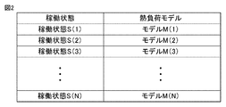
- FIG. 2 is a diagram showing an example of information stored in the model storage unit 101.
- the model storage unit 101 stores information representing the heat load models M (1) to M (N) corresponding to the operating states S (1) to S (N) of the air conditioning device.
- the model storage unit 101 uses the weight coefficient of the neural network as information representing the heat load models M (1) to M (N).
- the communication unit 104 is configured to be able to communicate with the control devices 11A and 11B via the telecommunication line 13.
- the model providing unit 102 receives a transmission request of the heat load model from any of the control devices 11A and 11B of the plurality of air conditioners.
- the model providing unit 102 determines the operating state of the air conditioner 2a among the plurality of learned heat load models stored in the model storage unit 101.
- a heat load model corresponding to the operating state having the same or maximum similarity is provided to the control device 11A of the air conditioner.
- the model providing unit 102 normalizes the value of each item representing the operating state of the air conditioner 2a and the value of each item representing the operating state stored in the model storage unit 101, thereby performing two operations. Normalize the state.
- the model providing unit 102 calculates the similarity between the operating state of the air conditioner 2a and the operating state stored in the model storage unit 101 by the Euclidean distance between the two normalized operating states.
- the model providing unit 102 determines the operating state of the air conditioner 2b among the plurality of learned heat load models stored in the model storage unit 101.
- a heat load model corresponding to the operating state having the same or maximum similarity is provided to the control device 11B of the air conditioner.
- the model providing unit 102 normalizes the value of each item representing the operating state of the air conditioner 2b and the value of each item representing the operating state stored in the model storage unit 101, thereby performing two operations. Normalize the state.
- the model providing unit 102 calculates the similarity between the operating state of the air conditioner 2b and the operating state stored in the model storage unit 101 by the Euclidean distance between the two normalized operating states.
- the above-mentioned calculation method of similarity is an example.
- the similarity calculation method may be any method as long as it is calculated based on the operating state.
- the normalized value may be weighted.
- the model registration unit 103 acquires a set of the operating state of the air conditioner sent from any of the control devices 11A and 11B and the learned heat load model.
- the model registration unit 103 stores the acquired learned heat load model in the model storage unit 101 in accordance with the acquired operating state of the air conditioner.
- the control device 11A includes a communication unit 114A, a learning unit 113A, a model storage unit 110A, a control unit 112A, and an operating state collecting unit 111A.
- the communication unit 114A is configured to be able to communicate with the model management device 10 through the telecommunication line 13.
- the model storage unit 110A further learns the trained heat load model acquired from the model management device 10 or the trained heat load model acquired from the model management device 10, and additionally learns the heat load model.
- the operating state collecting unit 111A collects information on the operating state of the air conditioner 2a.
- the control unit 112A issues a transmission request for a heat load model that specifies the operating state of the air conditioner 2a.
- the control unit 112A acquires the learned heat load model transmitted from the model management device 10 in response to the transmission request of the heat load model, and stores the trained heat load model in the model storage unit 110A.
- the trained heat load model transmitted from the model management device 10 corresponds to an operating state having the same or maximum similarity to the operating state of the air conditioner 2a included in the transmission request.
- the learning unit 113A acquires the input data and the teacher data of the heat load model for additional learning by operating the air conditioner 2a.
- the learning unit 113A additionally learns the heat load model stored in the model storage unit 110A by using the acquired input data and the teacher data.
- the control unit 112A controls the air conditioner 2a using the heat load model that has been additionally learned.
- the communication unit 115A executes a control command from the control unit 112A to the air conditioner 2a and a communication of sensor data from the air conditioner 2a to the control unit 112A.
- the communication unit 114A transmits the additionally learned heat load model to the model management device 10 together with the operating state of the air conditioner 2a.
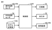
- FIG. 3 is a diagram showing an example of the configuration of the air conditioner 2a.
- the air conditioner 2a includes an outdoor unit 50 and a plurality of indoor units 40a and 40b.
- the outdoor unit 50 includes a compressor 51 that compresses and discharges the refrigerant, a heat source side heat exchanger 52 that exchanges heat between the outside air and the refrigerant, and a four-way valve 53 that switches the flow direction of the refrigerant according to the operation mode.
- the outdoor unit 50 includes an outside air temperature sensor 54 that detects the outside air temperature.
- the indoor unit 40a includes a load-side heat exchanger 41a in which heat is exchanged between indoor air and a refrigerant, and an expansion device 42a that decompresses and expands a high-pressure refrigerant.
- the indoor unit 40a includes an indoor temperature sensor 43a that detects room temperature.
- the indoor unit 40b includes a load-side heat exchanger 41b in which heat is exchanged between indoor air and a refrigerant, and an expansion device 42b that decompresses and expands a high-pressure refrigerant.
- the indoor unit 40b includes an indoor temperature sensor 43b that detects room temperature.
- the compressor 51 is, for example, an inverter type compressor whose capacity can be changed by changing the operating frequency.
- the expansion devices 42a and 42b are, for example, electronic expansion valves.
- the compressor 51, the heat source side heat exchanger 52, the expansion device 42a, and the load side heat exchanger 41a are connected to form a refrigerant circuit 60 in which the refrigerant circulates.
- the compressor 51, the heat source side heat exchanger 52, the expansion device 42b, and the load side heat exchanger 41b are connected to form a refrigerant circuit 60 in which the refrigerant circulates.
- FIG. 4 is a diagram for explaining an example of control of the air conditioner 2a by the control unit 112A.
- the control unit 112A determines the operating frequency of the compressor 51 and the expansion device based on the outside air temperature detected by the outside air temperature sensor 54, the room temperature detected by the indoor temperature sensor 43a, and the set temperature.
- the opening degree of 42a is controlled.
- the control unit 112A determines the operating frequency of the compressor 51 and the expansion device based on the outside air temperature detected by the outside air temperature sensor 54, the room temperature detected by the indoor temperature sensor 43b, and the set temperature.
- the opening degree of 42b is controlled.
- control unit 112A compresses based on the outside air temperature detected by the outside air temperature sensor 54, the room temperature and the set temperature of the indoor unit 40a, and the room temperature and the set temperature of the indoor unit 40b.
- the operating frequency of the machine 51 and the opening degrees of the expansion devices 42a and 42b are controlled.
- the control unit 112A switches the flow path of the four-way valve 53 depending on whether the operation mode of the air conditioner is the cooling operation mode or the heating operation mode.
- the control unit 112A controls the additional learning of the trained heat load model stored in the model storage unit 110A.
- the control unit 112A controls the air conditioner 2a by using the learned heat load model stored in the model storage unit 110A during operation.
- control of the air conditioner 2b by the control unit 112B is the same as the control of the air conditioner 2a by the control unit 112A, the description will not be repeated.
- the learning unit 113A generates a heat load model by using supervised learning using learning data.
- the learning unit 113A modifies the heat load model by using supervised learning using the additional learning data (additional learning).
- additional learning additional learning
- supervised learning by giving a large amount of a set of learning data consisting of inputs and results (labels) to the learning unit, the features of the learning data are learned. This allows the result to be estimated from the input (generalization).
- FIG. 5 is a diagram showing an example of a heat load model.
- the heat load model is configured by a neural network.
- a neural network is composed of an input layer composed of a plurality of neurons, an intermediate layer (hidden layer) composed of a plurality of neurons, and an output layer composed of a plurality of neurons.
- the intermediate layer may be one layer or two or more layers.
- Input data X (i) is given to the i-th unit of the input layer.
- Output data Z is output from the output layer.
- the input data X (1) to X (N) are data representing the influencing factors of the heat load of the air conditioner 2.
- the output data Z is data representing the heat load of the air conditioner 2.
- FIG. 6 is a diagram showing an example of input data of the heat load model.
- the input data of the heat load model is at least one of the difference between the set temperature and the outside air temperature, the difference between the set temperature and the room temperature, and the frequency of the compressor provided in the air conditioner 2. including.
- FIG. 7 is a diagram showing an example of output data of the heat load model. As shown in FIG. 7, the output data Z of the heat load model is the time from the start of operation of the indoor unit 40 until the indoor temperature reaches the set temperature.
- FIG. 8 is a diagram showing an example of an operating state.
- the operating state includes at least one of the type of the air conditioner 2, the environment in which the air conditioner 2 is installed, and the setting of the air conditioner 2.
- the type of the air conditioner 2 includes at least one of the number of outdoor units 50 of the air conditioner 2, the number of indoor units 40 of the air conditioner 2, and the serial number of the air conditioner 2.
- the environment in which the air conditioner 2 is installed includes at least one of the points where the air conditioner 2 is installed and the size of the room in which the air conditioner 2 is installed.
- the setting of the air conditioner 2 includes the amount of change in the room temperature within a certain period of time due to the operation of the air conditioner 2.
- the control unit 112A acquires a heat load model from the model management device 10 based on the operating state of the air conditioner 2a.
- the learning unit 113A additionally learns the acquired heat load model by using the learning data obtained at the time of the trial run.
- the control unit 112A gives input data to the heat load model after the additional learning during the operation of the air conditioner 2a, and acquires the output data of the heat load model after the additional learning.
- the input data is at least one of the difference between the set temperature and the outside air temperature, the difference between the set temperature and the room temperature, and the frequency of the compressor provided in the air conditioner.
- the output data is the time from the start of operation of the indoor unit 40 until the indoor temperature reaches the set temperature.
- the control unit 112A determines a schedule such as an operation start time of the air conditioner 2a based on the output data.
- FIG. 9 is a flowchart showing a procedure in which the control device 11A immediately after the operation according to the first embodiment acquires a heat load model from the model management device 10.
- step S101 the operating state collecting unit 111A of the control device 11A acquires the operating state of the air conditioner 2a.
- the air conditioner 2a the indoor temperature changed over a certain period of time, the number of outdoor units 50, and the number of indoor units 40 have a great influence on the control. Therefore, the operating state collecting unit 111A acquires such information.
- the upper and lower limits are set for the values of each item in the operating state.
- the operating state collecting unit 111A devalues the value of each item to the upper limit value.
- the operating state collecting unit 111A rounds up the value of each item to the lower limit value.
- step S102 the control unit 112A of the control device 11A issues a transmission request for the trained heat load model that specifies the operating state acquired in step S101.
- step S103 the communication unit 114A of the control device 11A transmits the transmission request of the learned heat load model for which the operating state is specified, which was issued in step S102, to the model management device 10.
- step S104 the communication unit 104 of the model management device 10 receives the transmission request of the trained heat load model for which the operating state is specified.
- step S105 the model providing unit 102 of the model management device 10 has learned that among the heat load models stored in the model storage unit 101, the operating state having the same or the highest degree of similarity to the designated operating state corresponds to the operating state.
- the heat load model of is output to the communication unit 104.
- step S106 the communication unit 104 of the model management device 10 transmits the learned heat load model output from the model providing unit 102 to the control device 11A that has issued the transmission request.
- step S107 the communication unit 114A of the control device 11A receives the trained heat load model.
- step S108 the control unit 112A of the control device 11A stores the received learned heat load model in the model storage unit 110A.
- FIG. 10 is a flowchart showing a procedure for additional learning by the control device 11A according to the first embodiment.
- step S201 the control unit 112A of the control device 11A makes the air conditioner 2a test run and acquires learning data for additional learning such as input data and teacher data.
- step S202 the control unit 112A of the control device 11A reads out the heat load model stored in the model storage unit 110A.
- the control unit 112A additionally learns the read heat load model by using the acquired learning data for additional learning.
- step S203 the operating state collecting unit 111A of the control device 11A acquires the operating state of the air conditioner 2a.
- the operating state collecting unit 111A acquires, for example, information on the indoor temperature that has changed in a certain period of time, the number of outdoor units 50, and the number of indoor units 40.
- step S204 the control unit 112A of the control device 11A issues a registration request including the operating state acquired in step S203 and the heat load model after additional learning.
- step S205 the communication unit 114A of the control device 11A transmits the registration request issued in step S204 to the model management device 10.
- step S206 the communication unit 104 of the model management device 10 receives a registration request including the operating state and the heat load model that has been additionally learned.
- step S207 the model registration unit 103 of the model management device 10 stores the additionally learned heat load model included in the registration request in the model storage unit 101 in response to the operating state included in the registration request.
- step S205 the following is executed in the control device 11A. Since the procedure for additional learning by the control device 11B is the same as that in FIG. 10, the description will not be repeated.
- the model management device 10 and the control devices 11A and 11B described in the above embodiment have the functions of the model management device 10 and the control devices 11A and 11B which can be configured by the hardware or software of the digital circuit.
- the model management device 10 and the control devices 11A and 11B include, for example, a processor 5002 connected by a bus 5003 and a memory 5001 as shown in FIG. 11, and are stored in the memory 5001.
- the processed program can be executed by the processor 5002.
- the processor 5002 includes a main processor, a communication processor, and the like.
- the memory 5001 is composed of a RAM, a flash memory, a hard disk, or the like.
- the heat load model of the air conditioner has been described as an example as a learned model shared among a plurality of control devices, but the present invention is not limited to this.
- the learned model to be shared any model may be used as long as it is used for controlling the controlled device.
- the operating state includes at least one of the type of controlled device, the environment in which the controlled device is installed, and the setting of the controlled device.
- the model management device 10 may exist on the cloud server.
- the neural network is applied as the learning algorithm of the heat load model has been described, but the present invention is not limited to this.
- Other machine learning algorithms such as support vector machines may be used.
- the same heat load model is used for the input data item and the output data item even if the operating states are different, but the present invention is not limited to this.
- a heat load model in which the input data item and the output data item are different depending on the operating state may be used.
- the procedure of the flowchart of FIG. 10 can be executed every day. On days when the air conditioner is not used, it is not necessary to determine the operation schedule of the air conditioner, so that the procedure shown in the flowchart of FIG. 10 may not be executed.
- 1 model sharing system 2a, 2b air conditioner, 10 model management device, 11A, 11B control device, 13 telecommunications line, 40a, 40b indoor unit, 41a, 41b load side heat exchanger, 42a, 42b expansion device, 43a , 43b Indoor temperature sensor, 50 outdoor unit, 51 compressor, 52 heat source side heat exchanger, 53 four-way valve, 54 outside air temperature sensor, 60 refrigerant circuit, 101, 110A model storage unit, 102 model provision unit, 103 model registration unit , 104, 114A, 115A, 114B, 115B communication unit, 111A, 111B operation status collection unit, 112A, 112B control unit, 113A, 113B learning unit, 5001 memory, 5002 processor, 5003 bus.
Landscapes
- Engineering & Computer Science (AREA)
- Signal Processing (AREA)
- Physics & Mathematics (AREA)
- Chemical & Material Sciences (AREA)
- Combustion & Propulsion (AREA)
- Mechanical Engineering (AREA)
- General Engineering & Computer Science (AREA)
- Fuzzy Systems (AREA)
- Mathematical Physics (AREA)
- General Physics & Mathematics (AREA)
- Automation & Control Theory (AREA)
- Air Conditioning Control Device (AREA)
Priority Applications (5)
| Application Number | Priority Date | Filing Date | Title |
|---|---|---|---|
| US17/760,851 US20220333810A1 (en) | 2019-12-13 | 2019-12-13 | Model sharing system, model management apparatus, and control apparatus for air conditioning apparatus |
| DE112019007970.0T DE112019007970T5 (de) | 2019-12-13 | 2019-12-13 | Modellteilungssystem, Modellverwaltungsvorrichtung und Steuerungsvorrichtung für Klimaanlagenvorrichtungen |
| PCT/JP2019/048993 WO2021117234A1 (ja) | 2019-12-13 | 2019-12-13 | モデル共有システム、モデル管理装置、および空気調和装置の制御装置 |
| CN201980102441.3A CN114761732B (zh) | 2019-12-13 | 2019-12-13 | 模型共享系统、模型管理装置以及空调装置的控制装置 |
| JP2021563571A JP7378497B2 (ja) | 2019-12-13 | 2019-12-13 | モデル共有システム、モデル管理装置、および空気調和装置の制御装置 |
Applications Claiming Priority (1)
| Application Number | Priority Date | Filing Date | Title |
|---|---|---|---|
| PCT/JP2019/048993 WO2021117234A1 (ja) | 2019-12-13 | 2019-12-13 | モデル共有システム、モデル管理装置、および空気調和装置の制御装置 |
Publications (1)
| Publication Number | Publication Date |
|---|---|
| WO2021117234A1 true WO2021117234A1 (ja) | 2021-06-17 |
Family
ID=76330123
Family Applications (1)
| Application Number | Title | Priority Date | Filing Date |
|---|---|---|---|
| PCT/JP2019/048993 Ceased WO2021117234A1 (ja) | 2019-12-13 | 2019-12-13 | モデル共有システム、モデル管理装置、および空気調和装置の制御装置 |
Country Status (5)
| Country | Link |
|---|---|
| US (1) | US20220333810A1 (https=) |
| JP (1) | JP7378497B2 (https=) |
| CN (1) | CN114761732B (https=) |
| DE (1) | DE112019007970T5 (https=) |
| WO (1) | WO2021117234A1 (https=) |
Cited By (1)
| Publication number | Priority date | Publication date | Assignee | Title |
|---|---|---|---|---|
| WO2024043206A1 (ja) * | 2022-08-26 | 2024-02-29 | 三菱重工サーマルシステムズ株式会社 | 制御装置、制御方法および空気調和機 |
Families Citing this family (1)
| Publication number | Priority date | Publication date | Assignee | Title |
|---|---|---|---|---|
| WO2021262754A1 (en) * | 2020-06-22 | 2021-12-30 | Laughmiller Micah | Innovative system for providing hyper efficient hvac |
Citations (3)
| Publication number | Priority date | Publication date | Assignee | Title |
|---|---|---|---|---|
| JPH0886490A (ja) * | 1994-09-14 | 1996-04-02 | Toshiba Corp | 熱負荷予測装置 |
| JP2016109422A (ja) * | 2014-12-04 | 2016-06-20 | 台達電子工業股▲ふん▼有限公司Delta Electronics,Inc. | 環境快適性制御システム及びその制御方法 |
| JP2019066135A (ja) * | 2017-10-04 | 2019-04-25 | ファナック株式会社 | 空調制御システム |
Family Cites Families (13)
| Publication number | Priority date | Publication date | Assignee | Title |
|---|---|---|---|---|
| JPH08275265A (ja) * | 1995-04-04 | 1996-10-18 | Tokyo Gas Co Ltd | 故障診断装置 |
| JP4661640B2 (ja) * | 2006-03-09 | 2011-03-30 | 株式会社日立製作所 | 空調制御システム |
| JP5224280B2 (ja) * | 2008-08-27 | 2013-07-03 | 株式会社デンソーアイティーラボラトリ | 学習データ管理装置、学習データ管理方法及び車両用空調装置ならびに機器の制御装置 |
| CH705980B1 (fr) * | 2012-01-12 | 2017-10-31 | Neurobat Ag | Système de régulation de la température dans une installation de chauffage d'un immeuble. |
| JP6120650B2 (ja) * | 2013-04-05 | 2017-04-26 | キヤノン株式会社 | コンテンツ管理装置、コンテンツ管理方法及びプログラム |
| CN105143780B (zh) * | 2013-04-15 | 2017-11-17 | 三菱电机株式会社 | 空调系统控制装置 |
| WO2015173842A1 (ja) * | 2014-05-12 | 2015-11-19 | 三菱電機株式会社 | パラメータ学習装置およびパラメータ学習方法 |
| WO2015174176A1 (ja) * | 2014-05-12 | 2015-11-19 | 三菱電機株式会社 | 換気制御装置および換気制御方法 |
| JP2016133294A (ja) * | 2015-01-22 | 2016-07-25 | ジョンソンコントロールズ ヒタチ エア コンディショニング テクノロジー(ホンコン)リミテッド | 空調機の保守・メンテナンスシステム及びその方法 |
| JPWO2017217131A1 (ja) * | 2016-06-15 | 2019-04-11 | 日本電気株式会社 | 建物熱モデル生成装置、建物熱モデル生成方法および建物熱モデル生成プログラム |
| JP2018071853A (ja) * | 2016-10-27 | 2018-05-10 | インフォグリーン株式会社 | 学習装置、制御装置、学習方法、制御方法、学習プログラムおよび制御プログラム |
| KR102440118B1 (ko) * | 2018-03-05 | 2022-09-05 | 삼성전자주식회사 | 공조 장치 및 그 제어 방법 |
| KR102457016B1 (ko) * | 2018-08-28 | 2022-10-19 | 에스케이텔레콤 주식회사 | 인공신경망을 이용한 공조기 최적 제어 장치 및 방법 |
-
2019
- 2019-12-13 JP JP2021563571A patent/JP7378497B2/ja active Active
- 2019-12-13 CN CN201980102441.3A patent/CN114761732B/zh active Active
- 2019-12-13 DE DE112019007970.0T patent/DE112019007970T5/de active Pending
- 2019-12-13 US US17/760,851 patent/US20220333810A1/en not_active Abandoned
- 2019-12-13 WO PCT/JP2019/048993 patent/WO2021117234A1/ja not_active Ceased
Patent Citations (3)
| Publication number | Priority date | Publication date | Assignee | Title |
|---|---|---|---|---|
| JPH0886490A (ja) * | 1994-09-14 | 1996-04-02 | Toshiba Corp | 熱負荷予測装置 |
| JP2016109422A (ja) * | 2014-12-04 | 2016-06-20 | 台達電子工業股▲ふん▼有限公司Delta Electronics,Inc. | 環境快適性制御システム及びその制御方法 |
| JP2019066135A (ja) * | 2017-10-04 | 2019-04-25 | ファナック株式会社 | 空調制御システム |
Cited By (2)
| Publication number | Priority date | Publication date | Assignee | Title |
|---|---|---|---|---|
| WO2024043206A1 (ja) * | 2022-08-26 | 2024-02-29 | 三菱重工サーマルシステムズ株式会社 | 制御装置、制御方法および空気調和機 |
| JP2024031381A (ja) * | 2022-08-26 | 2024-03-07 | 三菱重工サーマルシステムズ株式会社 | 制御装置、制御方法および空気調和機 |
Also Published As
| Publication number | Publication date |
|---|---|
| CN114761732A (zh) | 2022-07-15 |
| US20220333810A1 (en) | 2022-10-20 |
| JP7378497B2 (ja) | 2023-11-13 |
| JPWO2021117234A1 (https=) | 2021-06-17 |
| DE112019007970T5 (de) | 2022-09-22 |
| CN114761732B (zh) | 2024-03-19 |
Similar Documents
| Publication | Publication Date | Title |
|---|---|---|
| US11783203B2 (en) | Building energy system with energy data simulation for pre-training predictive building models | |
| US11473799B2 (en) | Systems and methods for intelligent pic valves with agent interaction | |
| US11372382B2 (en) | Building management system with augmented deep learning using combined regression and artificial neural network modeling | |
| Wei et al. | Multi-objective optimization of the HVAC (heating, ventilation, and air conditioning) system performance | |
| KR101973652B1 (ko) | Hvac 시스템에 대한 가변 공기 용적 모델링 | |
| Belic et al. | HVAC control methods-a review | |
| CA3040117C (en) | Operating an hvac system based on predicted indoor air temperature | |
| Ouf et al. | A simulation-based method to investigate occupant-centric controls | |
| US20180313564A1 (en) | Building network device for generating communication models for connecting building devices to a network | |
| US11243005B2 (en) | Determining the cause of a fault in an HVAC system | |
| US20240263825A1 (en) | A method of commissioning physical hvac devices of an hvac system for an hvac application | |
| JP7378497B2 (ja) | モデル共有システム、モデル管理装置、および空気調和装置の制御装置 | |
| CN118960162A (zh) | 基于人工智能的冷源群控方法、装置、设备以及存储介质 | |
| US12566006B2 (en) | System and method for refrigerant leak detection | |
| Rafeeq et al. | Remote supervision and control of air conditioning systems in different modes | |
| Aguilar et al. | Autonomic management of a building’s multi-HVAC system start-up | |
| WO2022101989A1 (ja) | 空気調和装置、および空気調和装置の学習装置 | |
| US11408626B2 (en) | Central plant control system with dynamic computation reduction | |
| Sierra et al. | Optimizing building’s environments performance using intelligent systems | |
| EP4657186A1 (en) | System and method for dynamically controlling operation of assets in an industrial environment | |
| EP4657199A1 (en) | System and method for managing cooling load within a building | |
| CN119603087A (zh) | 具有合成数据合规控制的建筑物系统 | |
| Pavarelli | Development of detailed HVAC system models for effective simulation of building performance at varying levels of automation | |
| Amanzadeh | Architecting IoT-Enabled Smart Building Testbed | |
| Moore et al. | Clarke JA Cockroj 1". Conne s'. Hand I w. Kelly NJ |
Legal Events
| Date | Code | Title | Description |
|---|---|---|---|
| 121 | Ep: the epo has been informed by wipo that ep was designated in this application |
Ref document number: 19955723 Country of ref document: EP Kind code of ref document: A1 |
|
| ENP | Entry into the national phase |
Ref document number: 2021563571 Country of ref document: JP Kind code of ref document: A |
|
| 122 | Ep: pct application non-entry in european phase |
Ref document number: 19955723 Country of ref document: EP Kind code of ref document: A1 |