WO2021107057A1 - 通信制御方法及びユーザ装置 - Google Patents
通信制御方法及びユーザ装置 Download PDFInfo
- Publication number
- WO2021107057A1 WO2021107057A1 PCT/JP2020/044117 JP2020044117W WO2021107057A1 WO 2021107057 A1 WO2021107057 A1 WO 2021107057A1 JP 2020044117 W JP2020044117 W JP 2020044117W WO 2021107057 A1 WO2021107057 A1 WO 2021107057A1
- Authority
- WO
- WIPO (PCT)
- Prior art keywords
- mobile network
- user device
- timing
- paging
- sim
- Prior art date
- Legal status (The legal status is an assumption and is not a legal conclusion. Google has not performed a legal analysis and makes no representation as to the accuracy of the status listed.)
- Ceased
Links
Images




Classifications
-
- H—ELECTRICITY
- H04—ELECTRIC COMMUNICATION TECHNIQUE
- H04W—WIRELESS COMMUNICATION NETWORKS
- H04W68/00—User notification, e.g. alerting and paging, for incoming communication, change of service or the like
- H04W68/02—Arrangements for increasing efficiency of notification or paging channel
-
- H—ELECTRICITY
- H04—ELECTRIC COMMUNICATION TECHNIQUE
- H04W—WIRELESS COMMUNICATION NETWORKS
- H04W8/00—Network data management
- H04W8/22—Processing or transfer of terminal data, e.g. status or physical capabilities
-
- H—ELECTRICITY
- H04—ELECTRIC COMMUNICATION TECHNIQUE
- H04W—WIRELESS COMMUNICATION NETWORKS
- H04W60/00—Affiliation to network, e.g. registration; Terminating affiliation with the network, e.g. de-registration
- H04W60/005—Multiple registrations, e.g. multihoming
-
- H—ELECTRICITY
- H04—ELECTRIC COMMUNICATION TECHNIQUE
- H04W—WIRELESS COMMUNICATION NETWORKS
- H04W8/00—Network data management
- H04W8/26—Network addressing or numbering for mobility support
-
- H—ELECTRICITY
- H04—ELECTRIC COMMUNICATION TECHNIQUE
- H04W—WIRELESS COMMUNICATION NETWORKS
- H04W88/00—Devices specially adapted for wireless communication networks, e.g. terminals, base stations or access point devices
- H04W88/02—Terminal devices
- H04W88/06—Terminal devices adapted for operation in multiple networks or having at least two operational modes, e.g. multi-mode terminals
Definitions
- This disclosure relates to a communication control method and a user device.
- the user device is a subscriber identification module (SIM: Subscriber) in order to use a mobile communication service (voice call service, data communication service, etc.) provided by a communication carrier (also referred to as an operator or a communication carrier) via a mobile network. It is necessary to install Identity Module).
- SIM subscriber identification module
- the user device is registered in the mobile network using SIM, the mobile communication service from the registration destination mobile network can be used.
- the user device equipped with the two SIMs uses the mobile communication service from the first mobile network, which is the mobile network to which the first SIM is registered, and also uses the mobile communication service.
- the mobile communication service from the second mobile network which is the mobile network to which the second SIM is registered, may be used. Discussions on use cases when using both mobile communication services have been started in 3GPP (Third Generation Partnership Project) (for example, Non-Patent Document 1).
- the communication control method is a communication control method using a user device.
- the user device registers with the first mobile network using the first subscriber identification module (SIM) and registers with the second mobile network using the second SIM.
- SIM subscriber identification module
- the communication control method provides setting information for setting either a non-execution timing in which the user device does not perform downlink transmission from the first mobile network to the user device or an execution timing in which the user device performs downlink transmission. It includes receiving from the first mobile network and transmitting specific information for specifying the timing set by the setting information to the second mobile network.
- the communication control method is a communication control method using a user device.
- the user device registers with the first mobile network using the first subscriber identification module (SIM) and registers with the second mobile network using the second SIM.
- SIM subscriber identification module
- the user device identifies a first paging reception opportunity, which is a candidate timing for the user device to receive a paging message from the first mobile network, and the user device determines the first paging reception opportunity. Identifying a second paging reception opportunity, which is a candidate timing for the user device to receive a paging message from the second mobile network, and the user device using the first mobile network and the second mobile network.
- the user device determines that the overlap timing exists, it has a first control or a second control.
- the first control is a control for receiving only a paging message from the priority mobile network at the overlap timing.
- the second control is a control for transmitting a request for changing the paging reception opportunity to the first mobile network and the non-priority mobile network of the second mobile network that is not the priority mobile network. Is.
- the user device is registered in the first mobile network using the first subscriber identification module (SIM) and registered in the second mobile network using the second SIM.
- SIM subscriber identification module
- the user device has a processor.
- the processor sets setting information from the first mobile network to set either a non-execution timing in which the downlink transmission is not performed from the first mobile network to the user device or an execution timing in which the downlink transmission is performed. Execute the process to receive.
- the processor executes a process of transmitting specific information for specifying the timing set by the setting information to the second mobile network.
- the user device is registered in the first mobile network using the first subscriber identification module (SIM) and registered in the second mobile network using the second SIM.
- the user device has a processor.
- the processor executes a process of identifying a first paging reception opportunity, which is a candidate timing for the user device to receive a paging message from the first mobile network.
- the processor executes a process of identifying a second paging reception opportunity, which is a candidate timing for the user device to receive a paging message from the second mobile network.
- the processor executes a process of identifying the preferred mobile network of the first mobile network and the second mobile network.
- the processor executes a process of determining whether or not there is an overlap timing in which the first paging reception opportunity and the second paging reception opportunity overlap.
- the processor executes a process of performing the first control or the second control.
- the first control is a control for receiving only a paging message from the priority mobile network at the overlap timing.
- the second control is a control for transmitting a request for changing the paging reception opportunity to the first mobile network and the non-priority mobile network of the second mobile network that is not the priority mobile network. Is.
- the user device When the user device has only a single wireless receiver and the downlink transmission from the first mobile network and the downlink transmission from the second mobile network occur at the same time, the first mobile network and It is possible that the downlink transmission from one of the second mobile networks cannot be received.
- the first mobile network and the second mobile network belong to different telecommunications carriers, it is difficult to avoid such a problem by coordinating between the mobile networks.
- An object of the present disclosure is to make it possible to avoid a collision of downlink transmission from a plurality of mobile networks in a user device capable of mounting a plurality of SIMs.
- the configuration of the mobile communication system according to the embodiment will be described.
- the mobile communication system according to one embodiment is a 5G system of 3GPP, but LTE may be applied to the mobile communication system at least partially.
- FIG. 1 is a diagram showing a configuration of a mobile communication system according to an embodiment.
- the mobile communication system is operated by a first mobile network 40-1 operated by a first telecommunications carrier and a second telecommunications carrier operated by a second telecommunications carrier different from the first telecommunications carrier. It has two mobile networks 40-2 and a user device (UE: User Equipment) 100.
- the UE 100 can be registered in the first mobile network 40-1 using the first SIM 140-1 described later, and can be registered in the second mobile network 40-2 using the second SIM 140-2.
- the first mobile network 40-1 and the second mobile network 40-2 are simply referred to as the mobile network 40.
- Each mobile network 40 has a 5G radio access network (NG-RAN: Next Generation Radio Access Network) 10 and a 5G core network (5GC: 5G Core Network) 20.
- NG-RAN Next Generation Radio Access Network
- 5GC 5G Core Network
- the UE100 is a movable device.
- the UE 100 may be any device as long as it is a device used by the user.
- the UE 100 is a mobile phone terminal (including a smartphone), a tablet terminal, a notebook PC, a communication module (including a communication card or a chip set), a sensor or a device provided in the sensor, a vehicle or a device provided in the vehicle (Vehicle UE). ) And / or a vehicle or a device (Aerial UE) provided on the vehicle.
- the NG-RAN 10 includes a base station (called "gNB” in a 5G system) 200.
- the gNB 200 is sometimes referred to as an NG-RAN node.
- the gNB 200s are connected to each other via an Xn interface (not shown), which is an interface between base stations.
- the gNB 200 manages one or more cells.
- the gNB 200 performs wireless communication with the UE 100 that has established a connection with its own cell.
- the gNB 200 has a radio resource management (RRM) function, a routing function for user data (hereinafter, simply referred to as “data”), and / or a measurement control function for mobility control / scheduling.
- RRM radio resource management
- Cell is used as a term to indicate the smallest unit of a wireless communication area.
- the term “cell” is also used to indicate a function or resource for wireless communication with the UE 100.
- One cell belongs to one carrier frequency.
- the gNB may be connected to the LTE core network EPC (Evolved Packet Core), or the LTE base station may be connected to the 5GC. Further, the LTE base station and the gNB may be connected via the inter-base station interface.
- EPC Evolved Packet Core
- 5GC20 includes AMF (Access and Mobility Management Function) and UPF (User Plane Function) 300.
- the AMF performs various mobility controls and the like for the UE 100.
- the AMF 300 manages information on the area in which the UE 100 is located by communicating with the UE 100 using NAS (Non-Access Stratum) signaling.
- UPF controls data transfer.
- the AMF and UPF are connected to the gNB 200 via the NG interface, which is a base station-core network interface.
- FIG. 2 is a diagram showing the configuration of the UE 100 (user device).
- the UE 100 has a receiving unit 110, a transmitting unit 120, a control unit 130, a SIM 140-1 (first SIM), a SIM 140-2 (second SIM), and a user interface 150.
- the UE 100 may have three or more SIM 140s.
- the receiving unit 110 performs various receptions under the control of the control unit 130.
- the receiving unit 110 includes an antenna and a receiver.
- the receiver converts the radio signal received by the antenna into a baseband signal (received signal) and outputs it to the control unit 130.
- the transmission unit 120 performs various transmissions under the control of the control unit 130.
- the transmitter 120 includes an antenna and a transmitter.
- the transmitter converts the baseband signal (transmission signal) output by the control unit 130 into a radio signal and transmits it from the antenna.
- the control unit 130 performs various controls on the UE 100.
- the control unit 130 includes at least one processor and at least one memory electrically connected to the processor.
- the memory stores a program executed by the processor and information used for processing by the processor.
- the processor may include a baseband processor and a CPU (Central Processing Unit).
- the baseband processor modulates / demodulates and encodes / decodes the baseband signal.
- the CPU executes a program stored in the memory to perform various processes.
- SIM140 records information that identifies a subscriber in order to receive a mobile communication service provided by a mobile network. In addition to the information for identifying the subscriber, the SIM 140 may record the carrier identification information for identifying the telecommunications carrier and the information regarding the available services contracted by the subscriber.
- the SIM 140 may be an IC card called a detachable SIM card (or USIM card), that is, an information card.
- the SIM 140 may be an embedded eSIM (Embedded SIM).
- the SIM 140-1 (first SIM) is the first IMSI (International Mobile Subscriber Identity), which is an identification number assigned to the user of the UE 100 by the first telecommunications carrier operating the first mobile network 40-1. ) Is recorded.
- the SIM 140-2 (second SIM) provides information for identifying the second IMSI, which is an identification number assigned to the user of the UE 100 by the second telecommunications carrier operating the second mobile network 40-2. Record.
- SIM140-1 and SIM140-2 may be separate information cards, or may be integrated into the same information card.
- SIM140-1 and SIM140-2 may be included in eSIM (Embedded SIM).
- SIM140-1 is managed by the first telecommunications carrier.
- SIM140-2 is managed by a second carrier. Note that SIM140-1 and SIM140-2 may be managed by the same telecommunications carrier.
- the UE 100 When the UE 100 registers with the first mobile network 40-1 using SIM 140-1, the UE 100 can use the mobile communication service provided by the first communication carrier via the first mobile network 40-1. Further, when the UE 100 registers with the second mobile network 40-2 using the SIM 140-2, the UE 100 uses the mobile communication service provided by the second communication carrier via the second mobile network 40-2. it can.
- the user of UE 100 may set the priority order of SIM 140-1 and SIM 140-2 via the user interface 150.
- the user may set SIM140-1 to take precedence over SIM140-2, or may set SIM140-2 to take precedence over SIM140-1.
- FIG. 3 is a diagram showing the configuration of gNB200 (base station).
- the gNB 200 includes a transmission unit 210, a reception unit 220, a control unit 230, and a backhaul communication unit 240.
- the transmission unit 210 performs various transmissions under the control of the control unit 230.
- the transmitter 210 includes an antenna and a transmitter.
- the transmitter converts the baseband signal (transmission signal) output by the control unit 230 into a radio signal and transmits it from the antenna.
- the receiving unit 220 performs various receptions under the control of the control unit 230.
- the receiving unit 220 includes an antenna and a receiver.
- the receiver converts the radio signal received by the antenna into a baseband signal (received signal) and outputs it to the control unit 230.
- the control unit 230 performs various controls on the gNB 200.
- the control unit 230 includes at least one processor and at least one memory electrically connected to the processor.
- the memory stores a program executed by the processor and information used for processing by the processor.
- the processor may include a baseband processor and a CPU.
- the baseband processor modulates / demodulates and encodes / decodes the baseband signal.
- the CPU executes a program stored in the memory to perform various processes.
- the backhaul communication unit 240 is connected to an adjacent base station via an interface between base stations.
- the backhaul communication unit 240 is connected to the AMF / UPF 300 via the base station-core network interface.
- FIG. 4 is a diagram showing the configuration of AMF300 (core network device).
- the AMF 300 includes a control unit 330 and a backhaul communication unit 340.
- the control unit 330 performs various controls on the AMF 300.
- the control unit 330 includes at least one processor and at least one memory electrically connected to the processor.
- the memory stores a program executed by the processor and information used for processing by the processor.
- the processor may include a baseband processor and a CPU.
- the baseband processor modulates / demodulates and encodes / decodes the baseband signal.
- the CPU executes a program stored in the memory to perform various processes.
- the backhaul communication unit 340 is connected to the gNB 200 via the base station-core network interface.
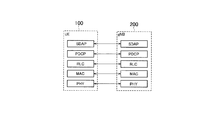
- FIG. 5 is a diagram showing a configuration of a protocol stack of a user plane wireless interface that handles data.
- the wireless interface protocol of the user plane includes a physical (PHY) layer, a MAC (Medium Access Control) layer, an RLC (Radio Link Control) layer, a PDCP (Packet Data Convergence Protocol) layer, and the like. It has an SDAP (Service Data Application Protocol) layer.
- PHY physical
- MAC Medium Access Control
- RLC Radio Link Control
- PDCP Packet Data Convergence Protocol
- SDAP Service Data Application Protocol
- the PHY layer performs encoding / decoding, modulation / demodulation, antenna mapping / demapping, and resource mapping / demapping. Data and control information are transmitted between the PHY layer of the UE 100 and the PHY layer of the gNB 200 via a physical channel.
- a frame structure containing radio frames, subframes, slots, and symbols is used.
- the wireless frame is composed of 10 subframes on the time axis.
- the length of each subframe is 1 ms.
- Each subframe is composed of a plurality of slots.
- Each slot is composed of a plurality of symbols.
- Each subframe contains a plurality of resource blocks (RBs) on the frequency axis.
- Each resource block contains a plurality of subcarriers on the frequency axis.
- the frequency resource can be specified by the resource block, and the time resource can be specified by the subframe (or slot, symbol).
- the section of the first number symbols of each subframe is an area mainly used as a physical downlink control channel (PDCCH: Physical Downlink Control Channel) for transmitting downlink control information.
- the remaining portion of each subframe is an area that can be used mainly as a physical downlink shared channel (PDSCH: Physical Downlink Shared Channel) for transmitting downlink data.
- PDSCH Physical Downlink Shared Channel
- the MAC layer performs data priority control, retransmission processing by hybrid ARQ (HARQ), random access procedure, and the like. Data and control information are transmitted between the MAC layer of the UE 100 and the MAC layer of the gNB 200 via the transport channel.
- the MAC layer of gNB200 includes a scheduler. The scheduler determines the transport format (transport block size, modulation / coding method (MCS)) of the upper and lower links and the resource block allocated to the UE 100.
- MCS modulation / coding method
- the RLC layer transmits data to the receiving RLC layer by using the functions of the MAC layer and the PHY layer. Data and control information are transmitted between the RLC layer of the UE 100 and the RLC layer of the gNB 200 via a logical channel.
- the PDCP layer performs header compression / decompression and encryption / decryption.
- the SDAP layer maps the IP flow, which is a unit for performing QoS control by the core network, with the wireless bearer, which is a unit for performing QoS control by AS (Access Stratum).
- AS Access Stratum
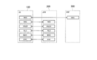
- FIG. 6 is a diagram showing a configuration of a protocol stack of a wireless interface of a control plane that handles signaling (control signal).
- the protocol stack of the radio interface of the control plane has an RRC (Radio Resource Control) layer and a NAS (Non-Access Stratum) layer in place of the SDAP layer shown in FIG.
- RRC signaling for various settings is transmitted between the RRC layer of UE100 and the RRC layer of gNB200.
- the RRC layer controls the logical, transport, and physical channels as the radio bearer is established, reestablished, and released.
- RRC connection connection between the RRC of the UE 100 and the RRC of the gNB 200
- the UE 100 is in the RRC connection state.
- RRC connection no connection between the RRC of the UE 100 and the RRC of the gNB 200
- the UE 100 is in the RRC idle state. Further, when the RRC connection is suspended, the UE 100 is in the RRC inactive state.
- the NAS layer located above the RRC layer performs session management, mobility management, etc.
- NAS signaling is transmitted between the NAS layer of the UE 100 and the NAS layer of the AMF 300.
- the UE 100 has an application layer and the like in addition to the wireless interface protocol.
- the UE 100 has only a single wireless receiver (receiver 110).
- the first mobile network 40-1 and the second mobile network 40-1 and the second There is a possibility that the downlink transmission from one of the mobile networks 40-2 of the mobile network 40-2 cannot be received.
- the first mobile network 40-1 and the second mobile network 40-2 belong to different communication carriers, it is difficult to avoid such a problem by cooperation between the mobile networks 40.
- a first embodiment for avoiding such a problem will be described.
- the UE 100 according to the first embodiment is registered in the first mobile network 40-1 using the first SIM (SIM140-1), and is registered in the second mobile network 40-1 using the second SIM (SIM140-2). Register at 40-2.
- the UE 100 sets setting information from the first mobile network 40-1 to set either a non-execution timing in which the downlink transmission is not performed from the first mobile network 40-1 to the UE 100 or an execution timing in which the downlink transmission is performed. Receive. The UE 100 transmits specific information for specifying the timing set by the setting information to the second mobile network 40-2. The UE 100 for which the non-execution timing is set is exempted from monitoring PDCCH at the non-execution timing.
- the timing of downlink transmission to the UE 100 by the second mobile network 40-2 so as to match the non-execution timing set in the UE 100 from the first mobile network 40-1. Can be determined. Further, in the second mobile network 40-2, the second mobile network 40-2 determines the timing of downlink transmission to the UE 100 so as to avoid the execution timing set in the UE 100 from the first mobile network 40-1. it can. Therefore, in the UE 100, it is possible to avoid a collision of downlink transmission from the first mobile network 40-1 and the second mobile network 40-2.
- An example of non-execution timing is the first mobile network 40 in order for the UE 100 in the RRC connection state in the first mobile network 40-1 to measure a carrier frequency different from the carrier frequency of the first mobile network 40-1.
- This is the measurement timing for interrupting communication with -1.
- Such measurement timing is sometimes referred to as a measurement gap.
- the measurement gap is set from the gNB 200 to the UE 100 by a dedicated RRC message containing the gap setting information that sets the measurement gap.
- the gap setting information includes information indicating the measurement cycle, the measurement start timing, and / or the duration of one measurement.
- the measurement cycle is sometimes referred to as a measurement gap repetition period (Measurement Gap Repetition Period (MGRP)).
- the duration of one measurement is sometimes referred to as the measurement gap length (Measurement Gap Length (MGL)).
- the combination of the measurement cycle and the duration of one measurement is sometimes referred to as the measurement gap pattern.
- the downlink communication period is specified by the downlink SPS (Semi-Persistent Scheduling) set in the UE 100 in the RRC connection state in the first mobile network 40-1.
- the cycle is set to UE100 by a dedicated RRC message, and the allocated resource block is specified to UE100 by PDCCH.
- the UE 100 uses the resource specified by PDCCH in the cycle set by RRC.
- execution timing is the timing of candidates for the UE 100 in the RRC idle state or the RRC inactive state to receive a paging message from the mobile network (first mobile network 40-1 or second mobile network). Such timing is called a paging reception opportunity.
- the UE 100 can perform a DRX (Discontinuation Reception) operation in order to reduce power consumption.
- the UE 100 in the RRC idle state or the RRC inactive state that performs the DRX operation intermittently monitors the PDCCH in order to receive paging for notifying information addressed to the UE 100 such as an incoming call.
- the UE 100 decodes the PDCCH using the paging group identifier (P-RNTI) and acquires the paging channel allocation information.
- P-RNTI paging group identifier
- the UE 100 acquires a paging message based on the allocation information.
- the PDCCH monitoring timing for paging in the DRX operation in the RRC idle state or the RRC inactive state is referred to as a paging opportunity (PO).
- the PO is associated with the paging frame (PF), which is a wireless frame.
- the PO associated with one PF may start in the PF or after the PF.
- the PO may be composed of one or a plurality of subframes in units of subframes.
- the PO may be composed of a plurality of symbols on a symbol-by-symbol basis.
- One PF is associated with one or more POs.
- the parameters that define the correspondence between the PF and PO are included in the paging-related information included in the SIB (System Information Block) broadcast by the gNB 200.
- SIB System Information Block
- the gNB 200 and the UE 100 calculate the PF and PO corresponding to the paging reception opportunity of the UE 100 as follows.
- the system frame number (SFN) of the PF corresponding to the paging reception opportunity of the UE 100 is obtained from the following formula (1).
- the PO corresponding to the paging reception opportunity of the UE 100 is determined by the index i_s obtained from the following equation (2).
- I_s floor (UE_ID / N) mod Ns ... (2)
- T is the DRX cycle of the UE 100 for monitoring paging.
- the DRX cycle is sometimes referred to as the paging cycle.
- the DRX cycle is represented by the number of radio frames.
- T is the smaller of the default DRX value broadcast by the gNB 200 by the SIB (System Information Block) and the UE-specific DRX value set in the UE 100.
- the UE-specific DRX value is set in the UE by an RRC message or a NAS message. If the UE-specific DRX value is not set, the UE 100 applies the default DRX value.
- N is the number of PFs in T.
- Ns is the number of POs associated with 1PF.
- UE_ID is a value obtained by "5G-S-TMSI mod 1024".
- PF_offset is a value used to determine the PF.
- N, Ns, and PF_offset are included in the paging-related information included in the SIB.
- the 5G-S-TMSI Temporal Mobile Subscriber Identity
- the 5G-S-TMSI Temporal Mobile Subscriber Identity is a temporary subscriber identifier assigned to the UE 100 by the AMF 300 when the UE 100 registers with the mobile network 40.
- the UE 100 monitors the paging (specifically, PDCCH).
- the gNB 200 transmits the paging to the UE 100 at the PF and PO corresponding to the paging reception opportunity of the UE 100.
- FIG. 7 is a diagram showing an operation according to the operation example 1 of the first embodiment. First, an outline of the operation according to the operation example 1 of the first embodiment will be described.
- the UE 100 is registered in the first mobile network 40-1 and the second mobile network 40-2.
- the UE 100 is in the RRC connection state in the first mobile network 40-1.
- the UE 100 is in the RRC idle state or the RRC inactive state in the second mobile network 40-2.
- step S101 the UE 100 receives the gap setting information from the gNB 200-1 belonging to the first mobile network 40-1.
- the UE 100 specifies a measurement gap to be set in the own UE 100 based on the gap setting information.
- step S102 the UE 100 transmits specific information for specifying the measurement gap set in the own UE 100 to the AMF300-2 belonging to the second mobile network 40-2.
- step S103 the AMF300-2 determines the paging reception opportunity of the UE 100 based on the measurement gap specified by the specific information.
- the AMF 300-2 transmits the determined information for setting the paging reception opportunity of the UE 100 (hereinafter, referred to as "paging setting information") to the UE 100.
- the paging setting information includes information indicating the above-mentioned 5G-S-TMSI, UE-specific DRX value, and the like.
- the UE 100 When transmitting the specific information in S102, the UE 100 transmits the specific information to the AMF 300-2 via the gNB 200-2.
- the UE 100 may transmit specific information along with a request to set or change a paging reception opportunity.
- the UE 100 When transmitting the specific information, the UE 100 performs a RACH (Random Access Channel) procedure on the gNB 200-2.
- the UE 100 may transmit specific information after establishing an RRC connection to the gNB 200-2.
- the UE 100 may transmit specific information along with the MSG3 message in the RACH procedure before establishing an RRC connection to the gNB 200-2.
- the UE 100 when the UE 100 transmits specific information after establishing the RRC connection, the UE 100 receives the paging setting information from the AMF300-2 via the gNB200-2 in the RRC connection state (step S104).
- the UE 100 when the UE 100 transmits specific information together with the MSG3 message, the UE 100 paging via the gNB 200-2 in a state where an RRC connection has not been established with the gNB 200-2 (RRC inactive state or RRC idle state).
- the setting information may be received from the AMF300-2 (step S104).
- the gNB 200-2 receives the specific information from the UE 100 together with the MSG3 message, the gNB 200-2 transfers the specific information to the AMF 300-2 without transmitting the message for establishing the RRC connection to the UE 100. Then, the gNB 200-2 transmits the paging setting information received from the AMF 300-2 to the UE 100.
- the UE 100 When transmitting the specific information, the UE 100 transmits the specific information in the measurement gap set from the first mobile network 40-1 so as not to adversely affect the communication with the first mobile network 40-1. You may send it. Alternatively, before transmitting the specific information (before step S102), the UE 100 requests the gNB200-1 to suspend the RRC connection, and transitions to a state in which the RRC connection is interrupted (RRC inactive state). Then, the specific information may be transmitted.
- the AMF300-2 determines the paging reception opportunity so that the paging reception opportunity for the UE 100 to receive the paging message from the second mobile network 40-2 is within the measurement gap. For example, the AMF300-2 first identifies a plurality of subframes corresponding to the measurement gap of the UE 100 by the specific information. Next, the AMF300-2 determines a part of the specified subframes as the PO corresponding to the paging reception opportunity of the UE 100. If necessary, the AMF300-2 may acquire the paging-related information contained in the SIB broadcast by the gNB200-2 from the gNB200-2 and determine the PO by referring to the paging-related information.
- step S104 the AMF300-2 transmits the paging setting information to the UE 100 via the gNB200-2.
- the above-mentioned MSG3 may be a message for requesting the recovery of the RRC connection in the RRC inactive state (RRCsumeRequest message), or a message for requesting the establishment of the RRC connection in the RRC idle state (RRCSetupRequest message). There may be.
- the UE 100 may transmit specific information when a predetermined trigger condition is satisfied.
- the trigger conditions for transmitting specific information will be described below.
- the predetermined trigger condition includes at least one of the following first to third conditions.
- the first condition is that the paging reception opportunity for the UE 100 to receive the paging message from the second mobile network 40-2 and the measurement gap set in the UE 100 from the first mobile network 40-1 do not overlap. That is. If there is an overlap timing in which the paging reception opportunity and the measurement gap overlap, the UE 100 can receive the paging at the overlap timing, so that it is not necessary to transmit specific information.
- the UE 100 After the UE 100 receives the gap setting information from the gNB200-1 (after the step S101) and before the step S102, the information contained in the SIB transmitted by the gNB200-2 and the information included in the SIB are registered in the second mobile network 40-2.
- the paging reception opportunity is specified based on the temporary subscriber identifier (5G-S-TMSI) assigned from AMF300-2.
- the UE 100 determines whether or not the specified paging reception opportunity and the measurement gap overlap, and if it determines that they do not overlap, the UE 100 transmits the specific information in step S102.
- the second condition is that the priority of the wireless bearer (bearer for transmitting and receiving user data) established by the UE 100 as the first mobile network 40-1 is equal to or higher than the threshold value.
- the priority of a radio bearer is determined by the type of traffic of user data mapped to that radio bearer. For example, when the traffic type is a voice call, the priority is determined to be high, and when the traffic type is mail, chat, and / or Web browsing, the priority is determined to be low.
- the reception of downlink user data on the wireless bearer does not collide with the paging reception opportunity corresponding to the second mobile network 40-2, so that the UE 100 Sends configuration information.
- the priority of the wireless bearer is low and the reception of downlink user data on the wireless bearer conflicts with the paging reception opportunity corresponding to the second mobile network 40-2, the reception of paging is performed on the user data.
- the UE 100 does not need to transmit specific information because it may take precedence over reception.
- the third condition is that the user possessing the UE 100 sets SIM140-1 corresponding to the first mobile network 40-1 to take precedence over SIM140-2 corresponding to the second mobile network 40-2. That is what you are doing.
- the setting information may set the pause period of the DRX operation in the RRC connection state as the non-execution timing.
- the specific information may specify a pause period as a non-execution timing.
- the specific information may specify the timing at which the UE 100 can receive the paging message.
- the AMF300-2 may determine the paging reception opportunity so that the paging reception opportunity is within the timing.
- the UE 100 may determine such a receivable timing based on the non-execution timing set from the first mobile network 40-1.
- FIG. 8 is a diagram showing an operation according to the operation example 2 of the first embodiment.
- the UE 100 is registered in the first mobile network 40-1 and the second mobile network.
- the UE 100 is in the RRC idle state or the RRC inactive state in the first mobile network 40-1.
- the UE 100 is in the RRC connection state in the second mobile network.
- the UE 100 has a paging reception opportunity for the UE 100 to receive a paging message from the gNB 200-1 belonging to the first mobile network 40-1 from the first mobile network 40-1.
- the setting information includes parameters for calculating the PF and PO corresponding to the paging reception opportunity included in the SIB broadcast by gNB200-1.
- Such parameters include the default DRX values described above, PF_offset, N, Ns and the like.
- the UE 100 specifies the PF and PO corresponding to the paging reception opportunity based on the parameters included in the setting information, the 5G-S-TMSI, and the UE-specific DRX value.
- the UE 100 transmits specific information for identifying the paging reception opportunity to the gNB 200-2 belonging to the second mobile network 40-2.
- the specific information may be information indicating the PF and PO corresponding to the paging reception opportunity specified by the UE 100.
- the specific information may be information for identifying the PF and PO (5G-S-TMSI, default DRX value, UE-specific DRX value, T, N, Ns, PF_offset, etc.).
- the gNB 200-2 determines the timing at which the downlink user data is not transmitted to the UE 100 based on the paging reception opportunity (PF and PO) specified by the specific information. For example, the gNB 200-2 determines the subframe belonging to the PO corresponding to the paging reception opportunity as the timing at which the downlink user data is not transmitted to the UE 100.
- PF and PO paging reception opportunity
- step S114 the gNB 200-2 transmits information for setting the determined timing to the UE 100.
- the UE 100 may transmit specific information when a predetermined trigger condition is satisfied.
- the predetermined trigger condition may include the third condition described above.
- FIG. 9 is a diagram showing an operation according to the operation example 3 of the first embodiment.
- the UE 100 is registered in the first mobile network 40-1 and the second mobile network 40-2.
- the UE 100 is in the RRC connection state in the first mobile network 40-1.
- the UE 100 is in the RRC connection state in the second mobile network 40-2.
- step S121 the UE 100 obtains setting information (information for setting the downlink SPS) for setting the downlink communication period from gNB200-1 belonging to the first mobile network 40-1. Receive. The UE 100 specifies the downlink communication period based on the setting information.
- step S122 the UE 100 transmits the specific information for specifying the downlink communication period set by the gNB200-1 to the gNB200-2 belonging to the second mobile network 40-2.
- the specific information may be information indicating a downlink communication period.
- the specific information may be information for setting the downlink SPS.
- step S123 the gNB 200-2 determines the timing at which the downlink user data is not transmitted to the UE 100 based on the downlink communication period specified by the specific information. For example, gNB200-2 determines a subframe belonging to the downlink communication period as a timing at which downlink user data is not transmitted to the UE 100.
- step S124 the gNB 200-2 transmits information for setting the determined timing to the UE 100.
- the trigger condition for the UE 100 to transmit specific information is not mentioned.
- the UE 100 transmits specific information when a predetermined trigger condition is satisfied.
- the predetermined trigger condition includes at least one of the above-mentioned second condition, the third condition, and the fourth condition described later.
- the fourth condition is that the priority of the radio bearer established by the UE 100 as the first mobile network 40-1 is higher than the priority of the radio bearer established by the UE 100 as the second mobile network 40-2. It's expensive.
- the UE 100 transmits specific information for specifying the execution timing or the non-execution timing set in the UE 100 by the first mobile network 40-1 to the second mobile network 40-2. It was possible to avoid the collision of downlink transmission. In the second embodiment, such a problem is solved mainly by the autonomous operation of the UE 100.
- the UE 100 according to the second embodiment is registered in the first mobile network 40-1 using the first SIM (SIM140-1), and is registered in the second mobile network 40-1 using the second SIM (SIM140-2). Register at 40-2.
- the UE 100 identifies a first paging reception opportunity for receiving a paging message from the first mobile network 40-1.
- the UE 100 identifies a second paging reception opportunity to receive a paging message from the second mobile network.
- the UE 100 identifies the preferred mobile network of the first mobile network 40-1 and the second mobile network.
- the UE 100 determines whether or not there is an overlap timing in which the first paging reception opportunity and the second paging reception opportunity overlap. When the UE 100 determines that the overlap timing exists, the UE 100 performs the first control or the second control.
- the first control is the control of receiving only the paging message from the priority mobile network at the overlapping timing.
- the second control is a control for transmitting a request for changing the paging reception opportunity to the non-priority mobile network of the first mobile network 40-1 and the second mobile network, which is not the preferred mobile network. is there.
- the transmission of the paging message from the first mobile network 40-1 and the second mobile network 40-2 conflicts in the UE 100, the reception of the paging message corresponding to the priority network can be ensured.
- the second control it is possible to avoid the collision of the transmission of the paging message from the first mobile network 40-1 and the second mobile network 40-2 in the UE 100.
- FIG. 10 is a diagram showing an operation according to the second embodiment.
- the UE 100 In the initial state of the second embodiment, the UE 100 is registered in the first mobile network 40-1 and the second mobile network 40-2.
- the UE 100 is in the RRC idle state or the RRC inactive state in the first mobile network 40-1.
- the UE 100 is in the RRC idle state or the RRC inactive state in the second mobile network 40-2.
- the UE 100 identifies a first paging reception opportunity (PF and PO) for receiving a paging message from the first mobile network 40-1.
- the paging reception opportunity is specified by the above-mentioned default DRX value, UE-specific DRX value, PF_offset, N, Ns, 5G-S-TMSI, and the like.
- step S202 the UE 100 identifies a second paging reception opportunity (PF and PO) for receiving a paging message from the second mobile network 40-2.
- the paging reception opportunity is specified by the above-mentioned default DRX value, UE-specific DRX value, PF_offset, N, Ns, 5G-S-TMSI, and the like.
- step S203 the UE 100 identifies the priority mobile network 40 of the second mobile network 40-2 and the first mobile network 40-1.
- the UE 100 identifies the priority mobile network 40 by the following first method or the second method.
- the first method is a method of specifying a mobile network 40 having a long paging cycle (that is, a value of T in the above equation (1)) as a priority mobile network 40.
- the number of POs corresponding to the paging reception opportunity of the UE 100 in the mobile network 40 having a short paging cycle is larger than the number of POs corresponding to the paging reception opportunity of the UE 100 in the mobile network 40 having a long paging cycle. Therefore, the UE 100 can receive the paging message from the mobile network 40 having a short paging cycle at another PO corresponding to the paging reception opportunity without receiving the paging message at the overlapping timing.
- the second method is a method of specifying the mobile network 40 corresponding to the SIM that the user has set as priority among SIM140-1 and SIM140-2 as the priority mobile network 40.
- the description will proceed on the assumption that the UE 100 specifies the first mobile network 40-1 as the priority mobile network and the second mobile network 40-2 as the non-priority mobile network.
- step S204 the UE 100 has an overlapping timing in which the first paging reception opportunity (PF and PO) specified in step S201 and the second paging reception opportunity (PF and PO) specified in step S202 overlap. Judge whether or not.
- step S205 the UE 100 receives only the paging message from the first mobile network 40-1 at the overlap timing (first control). Alternatively, in step S205, the UE 100 transmits a request for changing the paging reception opportunity to the second mobile network 40-2 (second control).
- the AMF300-2 belonging to the second mobile network 40-2 makes the request gNB200-2. Receive via.
- the AMF300-2 changes the temporary subscriber identifier (5G-S-TMSI) assigned to the UE 100 in response to the request.
- the AMF300-2 transmits information identifying the changed temporary subscriber identifier to the UE 100.
- changing the temporary subscriber identifier means generating a new temporary subscriber identifier or providing an offset to the temporary subscriber identifier already assigned to the UE 100.
- the information that identifies the changed temporary subscriber identifier may be information that indicates a new temporary subscriber identifier, or information that indicates an offset provided in the temporary subscriber identifier.
- the request for changing the paging reception opportunity transmitted from the UE 100 to the second mobile network 40-2 may be a change request (the change is left to the AMF300-2), and is assigned to the own UE100. It may be a request to change the temporary subscriber identifier (5G-S-TMSI) to a specific temporary subscriber identifier. In the latter case, the UE 100 specifies a new 5G-S-TMSI candidate, includes it in the request, and transmits it. The UE 100 may notify a portion of the 5G-S-TMSI or 5G-S-TMSI assigned from the mobile network 40-1 (eg, "UE_ID" above).
- the AMF300-2 transmits the paging message addressed to the UE 100 to the gNB 200-2 including the information indicating the offset when the UE 100 is paged.
- the UE 100 receives the setting information for setting the execution timing for downlink transmission from the first mobile network 40-1, and specifies the execution timing for performing the downlink transmission set by the setting information. The specific information for this was transmitted to the second mobile network 40-2.
- the UE 100 receives setting information for setting the execution timing for performing uplink transmission from the first mobile network 40-1, and specific information for specifying the uplink timing set by the setting information. May be transmitted to the second mobile network 40-2.
- An example of the execution timing for performing uplink transmission is a downlink communication period (hereinafter, simply referred to as “downlink communication period”) in which uplink resources are periodically allocated.
- the downlink communication period is specified by the uplink SPS set in the UE 100 in the RRC connection state in the first mobile network 40-1.
- the period is set to UE100 by a dedicated RRC message, and the allocated resource block is specified to UE100 by PDCCH.
- the UE 100 uses the resource specified by PDCCH in the cycle set by RRC.
- the UE 100 may notify the mobile network 40 when two SIM140s (SIM140-1 and SIM140-2) are used at the same time.
- SIM140-1 and SIM140-2 are used at the same time.
- the first mobile network 40-1 which has been registered first, sets a gap for the UE 100 to register and communicate with the second mobile network 40-2. May be good.
- the UE uses the gap setting to access the second mobile network 40-2.
- the UE 100 may notify the mobile network 40 to that effect.
- one mobile network 40 whose registration has been completed first may set a gap for the UE 100 to register and communicate with the remaining two mobile networks 40.
- a program that causes a computer to execute each process performed by the UE 100, gNB 200, and AMF 300 may be provided.
- the program may also be recorded on a computer-readable medium.
- Computer-readable media can be used to install programs on a computer.
- the computer-readable medium on which the program is recorded may be a non-transient recording medium.
- the non-transient recording medium is not particularly limited, but may be, for example, a recording medium such as a CD-ROM or a DVD-ROM.
- a chipset composed of a memory for storing a program for executing each process performed by the UE 100 and the eNB 200 and a processor for executing the program stored in the memory may be provided.
Landscapes
- Engineering & Computer Science (AREA)
- Computer Networks & Wireless Communication (AREA)
- Signal Processing (AREA)
- Databases & Information Systems (AREA)
- Mobile Radio Communication Systems (AREA)
Priority Applications (5)
| Application Number | Priority Date | Filing Date | Title |
|---|---|---|---|
| JP2021561521A JP7227401B2 (ja) | 2019-11-27 | 2020-11-26 | 通信制御方法及びユーザ装置 |
| EP20892258.3A EP4050957B1 (en) | 2019-11-27 | 2020-11-26 | Method and apparatus for avoiding paging collisions in a multi-sim user equipment |
| US17/825,668 US12457581B2 (en) | 2019-11-27 | 2022-05-26 | Communication control method and user equipment |
| JP2023018315A JP7516589B2 (ja) | 2019-11-27 | 2023-02-09 | 通信制御方法、ユーザ装置、プロセッサ、ネットワーク装置、プログラム及びシステム |
| US19/349,488 US20260032641A1 (en) | 2019-11-27 | 2025-10-03 | Communication control method and user equipment |
Applications Claiming Priority (2)
| Application Number | Priority Date | Filing Date | Title |
|---|---|---|---|
| JP2019-214616 | 2019-11-27 | ||
| JP2019214616 | 2019-11-27 |
Related Child Applications (1)
| Application Number | Title | Priority Date | Filing Date |
|---|---|---|---|
| US17/825,668 Continuation US12457581B2 (en) | 2019-11-27 | 2022-05-26 | Communication control method and user equipment |
Publications (1)
| Publication Number | Publication Date |
|---|---|
| WO2021107057A1 true WO2021107057A1 (ja) | 2021-06-03 |
Family
ID=76129538
Family Applications (1)
| Application Number | Title | Priority Date | Filing Date |
|---|---|---|---|
| PCT/JP2020/044117 Ceased WO2021107057A1 (ja) | 2019-11-27 | 2020-11-26 | 通信制御方法及びユーザ装置 |
Country Status (4)
| Country | Link |
|---|---|
| US (2) | US12457581B2 (https=) |
| EP (1) | EP4050957B1 (https=) |
| JP (2) | JP7227401B2 (https=) |
| WO (1) | WO2021107057A1 (https=) |
Families Citing this family (4)
| Publication number | Priority date | Publication date | Assignee | Title |
|---|---|---|---|---|
| JP7261761B2 (ja) * | 2020-03-10 | 2023-04-20 | Kddi株式会社 | 複数の加入者識別モジュールを有する端末装置への呼び出し制御を実行するための端末装置、コアネットワーク装置、制御方法、及びプログラム |
| US12294881B2 (en) * | 2020-07-10 | 2025-05-06 | Qualcomm Incorporated | User equipment (UE) measurement gap request and release for power savings and multiple subscriber identity module (MSIM) measurements |
| WO2022088073A1 (zh) * | 2020-10-30 | 2022-05-05 | 北京小米移动软件有限公司 | 寻呼配置方法和装置、寻呼方法和装置 |
| US20240064542A1 (en) * | 2022-08-19 | 2024-02-22 | Mediatek Inc. | Method and user equipment for performing cell measurement |
Citations (1)
| Publication number | Priority date | Publication date | Assignee | Title |
|---|---|---|---|---|
| JP2019214616A (ja) | 2011-04-08 | 2019-12-19 | ユニバーシティー オブ レスター | Masp−2依存性補体活性化に関連した状態を治療するための方法 |
Family Cites Families (8)
| Publication number | Priority date | Publication date | Assignee | Title |
|---|---|---|---|---|
| US20110122809A1 (en) * | 2009-11-20 | 2011-05-26 | Samsung Electronics Co. Ltd. | Method and apparatus for interworking of 3gpp lte and 3gpp2 legacy wireless communication systems |
| EP2737762B1 (en) * | 2011-07-25 | 2018-05-30 | Telefonaktiebolaget LM Ericsson (publ) | Paging reception in wireless communication devices with dual sim |
| US11076440B2 (en) * | 2014-05-28 | 2021-07-27 | Qualcomm Incorporated | Methods and apparatus for reducing collisions between CDRX and paging operations |
| US11356975B2 (en) * | 2018-12-14 | 2022-06-07 | Qualcomm Incorporated | Resolution of paging collisions in multisim and C-RAT operation |
| CN113557773B (zh) | 2019-03-06 | 2026-01-02 | 诺基亚技术有限公司 | 用以针对无线网络调节ue的寻呼定时的第二ue标识的指配 |
| US11368937B2 (en) * | 2019-04-12 | 2022-06-21 | Ofinno, Llc | Paging time adjustment in a wireless network |
| CN111918330B (zh) * | 2019-05-09 | 2025-04-18 | 三星电子株式会社 | 多通用用户标识模块用户设备及其操作方法 |
| CN118785369A (zh) * | 2019-06-17 | 2024-10-15 | 交互数字专利控股公司 | 用于具有多个usim的wtru的寻呼方法 |
-
2020
- 2020-11-26 JP JP2021561521A patent/JP7227401B2/ja active Active
- 2020-11-26 WO PCT/JP2020/044117 patent/WO2021107057A1/ja not_active Ceased
- 2020-11-26 EP EP20892258.3A patent/EP4050957B1/en active Active
-
2022
- 2022-05-26 US US17/825,668 patent/US12457581B2/en active Active
-
2023
- 2023-02-09 JP JP2023018315A patent/JP7516589B2/ja active Active
-
2025
- 2025-10-03 US US19/349,488 patent/US20260032641A1/en active Pending
Patent Citations (1)
| Publication number | Priority date | Publication date | Assignee | Title |
|---|---|---|---|---|
| JP2019214616A (ja) | 2011-04-08 | 2019-12-19 | ユニバーシティー オブ レスター | Masp−2依存性補体活性化に関連した状態を治療するための方法 |
Non-Patent Citations (3)
| Title |
|---|
| "TR 22.834 V17.1.0", 3GPP TECHNICAL REPORT TR 22.834, September 2019 (2019-09-01), Retrieved from the Internet <URL:http://www.3gpp.org/ftp/Specs/archive/22-series/22.834/22834-h10.zip> |
| INTEL, SONY, OPPO, INTERDIGITAL: "Solution for Paging Reception with PO collision avoidance", 3GPP TSG SA WG2 #136 S 2-1911942, 15 November 2019 (2019-11-15), XP051825715 * |
| SONY: "Solution for KI#3: Receiving Paging Occasions in other Networks", 3GPP TSG SA WG2 #136 S 2-1911145, 8 November 2019 (2019-11-08), XP051821247 * |
Also Published As
| Publication number | Publication date |
|---|---|
| US20220287004A1 (en) | 2022-09-08 |
| US12457581B2 (en) | 2025-10-28 |
| EP4050957B1 (en) | 2024-03-06 |
| EP4050957A4 (en) | 2023-01-04 |
| JP2023053106A (ja) | 2023-04-12 |
| JP7227401B2 (ja) | 2023-02-21 |
| JP7516589B2 (ja) | 2024-07-16 |
| EP4050957A1 (en) | 2022-08-31 |
| JPWO2021107057A1 (https=) | 2021-06-03 |
| US20260032641A1 (en) | 2026-01-29 |
Similar Documents
| Publication | Publication Date | Title |
|---|---|---|
| JP5826937B2 (ja) | 移動通信システム、基地局、ユーザ端末、及びプロセッサ | |
| JP5893141B2 (ja) | 移動通信システム、ユーザ端末、プロセッサ及び基地局 | |
| EP3100374B1 (en) | Method for handling an id collision for d2d communication system and device therefor | |
| JP7516589B2 (ja) | 通信制御方法、ユーザ装置、プロセッサ、ネットワーク装置、プログラム及びシステム | |
| US10028294B2 (en) | Method for notifying for D2D communication system and device therefor | |
| US10098162B2 (en) | Mobile communication system, user terminal, base station, processor, and communication control method | |
| EP3404981B1 (en) | Wireless terminal | |
| JP2019134476A (ja) | 基地局 | |
| EP2861009A1 (en) | Mobile communication system and user terminal | |
| JP5842061B2 (ja) | 移動通信システム、ユーザ端末、及びプロセッサ | |
| EP2861027A1 (en) | Communication control method and base station | |
| US20230403626A1 (en) | Method and apparatus for relay communication | |
| WO2016031662A1 (ja) | 基地局及び無線lan終端装置 | |
| EP4192039B1 (en) | Communication control method |
Legal Events
| Date | Code | Title | Description |
|---|---|---|---|
| 121 | Ep: the epo has been informed by wipo that ep was designated in this application |
Ref document number: 20892258 Country of ref document: EP Kind code of ref document: A1 |
|
| ENP | Entry into the national phase |
Ref document number: 2021561521 Country of ref document: JP Kind code of ref document: A |
|
| ENP | Entry into the national phase |
Ref document number: 2020892258 Country of ref document: EP Effective date: 20220527 |
|
| NENP | Non-entry into the national phase |
Ref country code: DE |