WO2021106739A1 - 歯列矯正具の提供方法 - Google Patents
歯列矯正具の提供方法 Download PDFInfo
- Publication number
- WO2021106739A1 WO2021106739A1 PCT/JP2020/043205 JP2020043205W WO2021106739A1 WO 2021106739 A1 WO2021106739 A1 WO 2021106739A1 JP 2020043205 W JP2020043205 W JP 2020043205W WO 2021106739 A1 WO2021106739 A1 WO 2021106739A1
- Authority
- WO
- WIPO (PCT)
- Prior art keywords
- mouthpiece
- orthodontic
- protrusion
- shape
- auxiliary
- Prior art date
- Legal status (The legal status is an assumption and is not a legal conclusion. Google has not performed a legal analysis and makes no representation as to the accuracy of the status listed.)
- Ceased
Links
Images

Classifications
-
- A—HUMAN NECESSITIES
- A61—MEDICAL OR VETERINARY SCIENCE; HYGIENE
- A61C—DENTISTRY; APPARATUS OR METHODS FOR ORAL OR DENTAL HYGIENE
- A61C7/00—Orthodontics, i.e. obtaining or maintaining the desired position of teeth, e.g. by straightening, evening, regulating, separating, or by correcting malocclusions
- A61C7/12—Brackets; Arch wires; Combinations thereof; Accessories therefor
- A61C7/14—Brackets; Fixing brackets to teeth
-
- A—HUMAN NECESSITIES
- A61—MEDICAL OR VETERINARY SCIENCE; HYGIENE
- A61C—DENTISTRY; APPARATUS OR METHODS FOR ORAL OR DENTAL HYGIENE
- A61C7/00—Orthodontics, i.e. obtaining or maintaining the desired position of teeth, e.g. by straightening, evening, regulating, separating, or by correcting malocclusions
- A61C7/08—Mouthpiece-type retainers or positioners, e.g. for both the lower and upper arch
-
- A—HUMAN NECESSITIES
- A61—MEDICAL OR VETERINARY SCIENCE; HYGIENE
- A61C—DENTISTRY; APPARATUS OR METHODS FOR ORAL OR DENTAL HYGIENE
- A61C7/00—Orthodontics, i.e. obtaining or maintaining the desired position of teeth, e.g. by straightening, evening, regulating, separating, or by correcting malocclusions
- A61C7/002—Orthodontic computer assisted systems
-
- A—HUMAN NECESSITIES
- A61—MEDICAL OR VETERINARY SCIENCE; HYGIENE
- A61C—DENTISTRY; APPARATUS OR METHODS FOR ORAL OR DENTAL HYGIENE
- A61C7/00—Orthodontics, i.e. obtaining or maintaining the desired position of teeth, e.g. by straightening, evening, regulating, separating, or by correcting malocclusions
- A61C7/10—Devices having means to apply outwardly directed force, e.g. expanders
-
- A—HUMAN NECESSITIES
- A61—MEDICAL OR VETERINARY SCIENCE; HYGIENE
- A61C—DENTISTRY; APPARATUS OR METHODS FOR ORAL OR DENTAL HYGIENE
- A61C7/00—Orthodontics, i.e. obtaining or maintaining the desired position of teeth, e.g. by straightening, evening, regulating, separating, or by correcting malocclusions
- A61C7/12—Brackets; Arch wires; Combinations thereof; Accessories therefor
- A61C7/14—Brackets; Fixing brackets to teeth
- A61C7/146—Positioning or placement of brackets; Tools therefor
-
- A—HUMAN NECESSITIES
- A61—MEDICAL OR VETERINARY SCIENCE; HYGIENE
- A61C—DENTISTRY; APPARATUS OR METHODS FOR ORAL OR DENTAL HYGIENE
- A61C9/00—Impression cups, i.e. impression trays; Impression methods
- A61C9/004—Means or methods for taking digitized impressions
- A61C9/0046—Data acquisition means or methods
-
- B—PERFORMING OPERATIONS; TRANSPORTING
- B33—ADDITIVE MANUFACTURING TECHNOLOGY
- B33Y—ADDITIVE MANUFACTURING, i.e. MANUFACTURING OF THREE-DIMENSIONAL [3D] OBJECTS BY ADDITIVE DEPOSITION, ADDITIVE AGGLOMERATION OR ADDITIVE LAYERING, e.g. BY 3D PRINTING, STEREOLITHOGRAPHY OR SELECTIVE LASER SINTERING
- B33Y80/00—Products made by additive manufacturing
Definitions
- the present invention relates to a method for providing an orthodontic appliance, and particularly to a method for performing orthodontic treatment using a mouthpiece precisely, with high degree of freedom and high efficiency.
- Mouthpiece type orthodontic appliances have been provided conventionally.
- the mouthpiece is worn so as to cover all or part of the dentition.
- a pressing force is applied to some teeth in a direction intended in advance.
- the position of the teeth is gradually adjusted.
- the dentist develops a series of orthodontic plans consisting of multiple steps, and the supplier prepares the mouthpiece to be used in each process according to the plan.
- the patient changes the mouthpiece one after another step by step and gradually adjusts the dentition to the correct position.
- the process of making a mouthpiece is roughly as follows.
- the dentist obtains the patient's oral scan data and dental model, and creates an orthodontic plan.
- the supplier creates the 3D data of the oral scan data or the dental model and the 3D CAD data of the mouthpiece used in each step of the orthodontic plan according to the orthodontic plan.
- a mouthpiece is manufactured using, for example, a stereolithography 3D printer using a photocurable resin.
- Patent Document 1 describes that the magnitude and direction of the force applied to the tooth can be freely adjusted by changing the thickness of the mouthpiece at the spot of the tooth to be corrected.
- Patent Document 1 has a problem that special know-how is required for its design.
- the present invention has been made to solve such a problem, and provides a method for providing an orthodontic appliance capable of performing orthodontic treatment precisely, with a high degree of freedom and with high efficiency. With the goal.
- the method of providing the orthodontic appliance according to the embodiment of the present invention is based on the shape of the oral cavity, the shape of the protrusion to be adhered to the tooth to be corrected, and the adhesion position, and the three-dimensional data of the auxiliary mouthpiece. And the step of creating the three-dimensional data of the correction mouthpiece, the step of creating the auxiliary mouthpiece having the recess corresponding to the protrusion piece based on the three-dimensional data of the auxiliary mouthpiece, and the step of creating the correction mouth.
- a step of producing the corrective mouthpiece having a pressing portion in contact with the protruding piece based on the three-dimensional data of the piece is included.
- the method of providing an orthodontic appliance according to an embodiment of the present invention is based on the shape of the oral cavity, the shape of the protrusion to be adhered to the tooth to be corrected, and the adhesion position, and the recess corresponding to the protrusion.
- Orthodontics having a pressing portion that comes into contact with the protruding piece based on the step of producing the auxiliary mouthpiece having the above, the shape of the oral cavity, the shape and the bonding position of the protruding piece to be adhered to the tooth to be corrected. Includes steps to create a mouthpiece for.
- the auxiliary mouthpiece according to the embodiment of the present invention has a recess corresponding to a protrusion to be adhered to the tooth to be corrected.
- the orthodontic mouthpiece according to the embodiment of the present invention has a pressing portion that comes into contact with the protrusions adhered to the orthodontic tooth to generate a force applied to the orthodontic tooth.
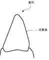
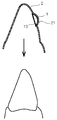
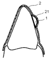
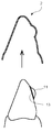
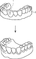
- 1A, 1B, 1C, 1D, 2A and 2B are schematic views for explaining an orthodontic process using an orthodontic appliance according to the present invention.
- Orthodontics consists of two main processes. (1) Process of adhering the protrusion 1 to the tooth to be corrected (hereinafter, simply referred to as the target tooth) (2) Process of attaching the correction mouthpiece 3 from above the protrusion 1
- FIG. 1A is a cross-sectional view of the target tooth before orthodontics as viewed from the lateral direction.
- the right side of the figure corresponds to the outside of the target tooth, and the left side corresponds to the inside.
- the protrusion 1 is first adhered to the surface of the target tooth.
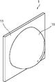
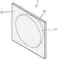
- 5 and 6 show the appearance of the protrusion 1.
- the protrusion 1 in the present embodiment has a hemispherical protrusion 11 and a base 13.
- the back side of the base portion 13 is an adhesive surface 131, and an adhesive is applied.
- the adhesive surface 131 By bringing the adhesive surface 131 into close contact with the surface of the target tooth, the protrusion 1 adheres to the target tooth.
- FIG. 1B is a diagram showing a state before the auxiliary mouthpiece 2 is attached to the dentition. Further, FIG. 7 shows a perspective view of this state.
- the auxiliary mouthpiece 2 is a mouthpiece used for the purpose of adhering the protrusion 1 to the target tooth.
- the inner surface shape of the auxiliary mouthpiece 2 is formed so as to fit the dentition before orthodontics.
- a recess 21 having a shape in which the protrusion 1 fits is formed in a part of the auxiliary mouthpiece 2.
- a protrusion 1 is set inside the recess 21 so that the adhesive surface 131 faces the surface of the target tooth. In this way, the protrusion 1 is provided to the patient in a state of being set in the auxiliary mouthpiece 2.
- FIG. 1C is a diagram showing a state in which the auxiliary mouthpiece 2 is attached to the dentition. In this state, the adhesive surface 131 of the protrusion 1 adheres to the surface of the target tooth, and the protrusion 1 adheres to a predetermined position of the target tooth.
- FIG. 1D is a diagram showing a state in which the auxiliary mouthpiece 2 is removed from the dentition. Since the protrusion 1 is adhered to the surface of the target tooth, the auxiliary mouthpiece 2 is separated from the protrusion 1 when it is removed.
- the material of the auxiliary mouthpiece 2 is preferably one having appropriate rigidity and elasticity so that the auxiliary mouthpiece 2 can be attached to the dentition and the protrusion 1 can be smoothly and surely detached.
- a biocompatible transparent resin or the like for example, a resin can be used.
- the shape of the auxiliary mouthpiece 2 is arbitrary as long as it fits around the target tooth to such an extent that the protrusion 1 can be positioned at a predetermined position of the target tooth. For example, it may cover the entire dentition, a part of the dentition, or only the front surface or the back surface of the dentition.
- the typical manufacturing method of the auxiliary mouthpiece 2 is as follows. First, three-dimensional CAD data that is the basis of the auxiliary mouthpiece 2 is created based on the data indicating the shape in the oral cavity.
- the data showing the shape in the oral cavity includes, for example, three-dimensional scan data in the oral cavity, CT data, X-ray data, three-dimensional scan data of a dental model, and the like.
- three-dimensional CAD data of the auxiliary mouthpiece 2 provided with the recess 21 is created based on the shape to be used and the position to be adhered to the target tooth.
- the created 3D CAD data is transferred to the 3D printer, and the auxiliary mouthpiece 2 is output.
- the protrusion 1 is not limited to the hemispherical protrusion 11 described above, and may have a protrusion 11 having an arbitrary shape such as a square (cone, pyramid).
- the shape of the adhesive surface 131 is not limited to a rectangle, and may be changed as appropriate.
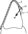
- FIG. 2A is a diagram showing a state before the orthodontic mouthpiece 3 is attached to the dentition.
- the protrusion 1 is already adhered to the target tooth.
- the orthodontic mouthpiece 3 is a mouthpiece for applying a predetermined force to the target tooth for orthodontic treatment.
- the inner surface shape of the orthodontic mouthpiece 3 may be formed so as to give some orthodontic force to the target tooth like the conventional orthodontic mouthpiece, and fits the current dentition without generating the orthodontic force. It may be formed as follows.
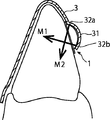
- a recess 31 corresponding to the protrusion 1 is formed in a part of the correction mouthpiece 3.
- a pressing portion 32 is provided in the recess 31.
- a plurality of pressing portions 32 formed in a convex shape are provided (pressing portions 32a and pressing portions 32b), but the shape and number of the pressing portions 32 are arbitrary. That is, it suffices if a part of the correction mouthpiece 3 is formed so as to come into contact with the protrusion 11, and the contact point becomes the pressing portion 32.
- FIG. 2B is a diagram showing a state in which the orthodontic mouthpiece 3 is attached to the dentition.
- the direction and size of the straightening force M can be easily adjusted by changing the position and size of the pressing portion 32 when the convex pressing portion 32 is provided as in the present embodiment. Further, the straightening force M can be adjusted by the thickness and shape of the recess 31.
- FIG. 3 is a diagram showing another form of the orthodontic mouthpiece 3.
- the recess 31 is formed so as to cover at least a part of the protrusion 1, and the contact point (or contact surface) between the protrusion 11 and the recess 31 functions as a pressing portion 32 to generate a straightening force M. ..
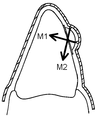
- FIG. 4 is a diagram showing another form of the orthodontic mouthpiece 3.
- the inside of the recess 31 is in contact with the protrusion 11 at one or more contact points (or contact surfaces) to form one or more pressing portions 32.
- two pressing portions 32 are formed to generate corrective forces M1 and M2.
- the typical manufacturing method of the orthodontic mouthpiece 3 is as follows. First, three-dimensional CAD data, which is the basis of the orthodontic mouthpiece 3, is created based on the data showing the shape in the oral cavity.
- the data showing the shape in the oral cavity includes, for example, three-dimensional scan data in the oral cavity, CT data, X-ray data, three-dimensional scan data of a dental model, and the like.
- three-dimensional CAD data of the correction mouthpiece 3 provided with the recess 31 and the pressing portion 32 is created based on the bonding position and shape of the protrusion piece 1.
- the created 3D CAD data is transferred to a 3D printer, and the correction mouthpiece 3 is output.
- a biocompatible transparent resin or the like for example, a resin can be used.
- the straightening force can be adjusted by adjusting the thickness of the material at least in the recess 31 and its periphery. If the thickness of the material is increased, the orthodontic force that can be applied to the target tooth through the protrusion 1 is increased, so that the target tooth can be moved more greatly.
- the orthodontic force M can be applied to the target tooth by contacting the protrusion 1 adhered to the target tooth with the pressing portion 32 of the orthodontic mouthpiece 3.
- the straightening force M can be set precisely and flexibly by adjusting the bonding position of the protrusion 1 and the forming position of the pressing portion 32.
- the orthodontic mouthpiece 3 can efficiently transmit the orthodontic force to the target tooth. Therefore, it is possible to have a higher straightening force than the conventional straightening mouthpiece. Alternatively, the same straightening force as the conventional one can be realized with a thinner material.
- the auxiliary mouthpiece 2 and the protrusion 1 are re-provided if there is the latest design data of the auxiliary mouthpiece 2. It is easy to do. As a result, the protrusion 1 can be installed again at the exact same position.
- the present invention is not limited to the above-described embodiment, and may be arbitrarily modified as long as the gist of the present invention is not impaired.
- the shape of the protrusion 1, the shape of the recess 21 or 31, the contact position between the protrusion 1 and the recess 31, the shape of the contact portion, the material of each member, and the like should be appropriately changed according to the purpose of correction and the like. Can be done.
Landscapes
- Health & Medical Sciences (AREA)
- General Health & Medical Sciences (AREA)
- Veterinary Medicine (AREA)
- Epidemiology (AREA)
- Life Sciences & Earth Sciences (AREA)
- Animal Behavior & Ethology (AREA)
- Oral & Maxillofacial Surgery (AREA)
- Public Health (AREA)
- Dentistry (AREA)
- Engineering & Computer Science (AREA)
- General Engineering & Computer Science (AREA)
- Chemical & Material Sciences (AREA)
- Manufacturing & Machinery (AREA)
- Materials Engineering (AREA)
- Dental Tools And Instruments Or Auxiliary Dental Instruments (AREA)
Priority Applications (4)
| Application Number | Priority Date | Filing Date | Title |
|---|---|---|---|
| KR1020227018916A KR102949795B1 (ko) | 2019-11-29 | 2020-11-19 | 치열 교정구의 제공 방법 |
| CN202080082184.4A CN114727854A (zh) | 2019-11-29 | 2020-11-19 | 齿列矫正器具的提供方法 |
| EP20893918.1A EP4066778A4 (en) | 2019-11-29 | 2020-11-19 | METHOD FOR PROVIDING AN ORTHODONTIC TOOL |
| US17/780,572 US20220409340A1 (en) | 2019-11-29 | 2020-11-19 | Method for providing orthodontic appliance |
Applications Claiming Priority (2)
| Application Number | Priority Date | Filing Date | Title |
|---|---|---|---|
| JP2019-216619 | 2019-11-29 | ||
| JP2019216619A JP2021083926A (ja) | 2019-11-29 | 2019-11-29 | 歯列矯正具の提供方法 |
Publications (1)
| Publication Number | Publication Date |
|---|---|
| WO2021106739A1 true WO2021106739A1 (ja) | 2021-06-03 |
Family
ID=76086422
Family Applications (1)
| Application Number | Title | Priority Date | Filing Date |
|---|---|---|---|
| PCT/JP2020/043205 Ceased WO2021106739A1 (ja) | 2019-11-29 | 2020-11-19 | 歯列矯正具の提供方法 |
Country Status (6)
| Country | Link |
|---|---|
| US (1) | US20220409340A1 (cg-RX-API-DMAC7.html) |
| EP (1) | EP4066778A4 (cg-RX-API-DMAC7.html) |
| JP (2) | JP2021083926A (cg-RX-API-DMAC7.html) |
| KR (1) | KR102949795B1 (cg-RX-API-DMAC7.html) |
| CN (1) | CN114727854A (cg-RX-API-DMAC7.html) |
| WO (1) | WO2021106739A1 (cg-RX-API-DMAC7.html) |
Cited By (1)
| Publication number | Priority date | Publication date | Assignee | Title |
|---|---|---|---|---|
| EP4311518A1 (en) * | 2022-07-26 | 2024-01-31 | Orthodontic Research and Development, S.L. | Attachments for use in orthodontic treatments |
Families Citing this family (1)
| Publication number | Priority date | Publication date | Assignee | Title |
|---|---|---|---|---|
| FR3125959B1 (fr) * | 2021-08-06 | 2024-05-24 | Valere Frederic | Appareil dentaire amovible |
Citations (5)
| Publication number | Priority date | Publication date | Assignee | Title |
|---|---|---|---|---|
| JP2001190569A (ja) * | 2000-01-17 | 2001-07-17 | Rinkai Kk | 歯科矯正に用いるブラケット取付用コア |
| JP2002531167A (ja) * | 1998-11-30 | 2002-09-24 | アライン テクノロジー, インコーポレイテッド | 歯の器具に関する装着デバイスおよび方法 |
| JP2011525848A (ja) * | 2008-06-26 | 2011-09-29 | スリーエム イノベイティブ プロパティズ カンパニー | 歯列矯正装具用のラピッドプロトタイプ移動トレー |
| JP2018094245A (ja) | 2016-12-15 | 2018-06-21 | 岡本化学工業株式会社 | 歯科矯正用アライナー及びその製造方法 |
| JP2019511323A (ja) * | 2016-04-14 | 2019-04-25 | スリーエム イノベイティブ プロパティズ カンパニー | 歯の協調移動を促進する歯科矯正装置 |
Family Cites Families (18)
| Publication number | Priority date | Publication date | Assignee | Title |
|---|---|---|---|---|
| US6705863B2 (en) * | 1997-06-20 | 2004-03-16 | Align Technology, Inc. | Attachment devices and methods for a dental appliance |
| US6299440B1 (en) * | 1999-01-15 | 2001-10-09 | Align Technology, Inc | System and method for producing tooth movement |
| US7771195B2 (en) * | 2001-10-29 | 2010-08-10 | Align Technology, Inc. | Polar attachment devices and method for a dental appliance |
| US6830450B2 (en) * | 2002-04-18 | 2004-12-14 | Align Technology, Inc. | Systems and methods for improved engagement between aligners and teeth |
| JP4150376B2 (ja) | 2005-01-13 | 2008-09-17 | 裕之 石川 | 歯列矯正用具 |
| JP4556941B2 (ja) | 2006-03-28 | 2010-10-06 | パナソニック電工株式会社 | 歯列矯正装置 |
| JP4333730B2 (ja) | 2006-11-27 | 2009-09-16 | パナソニック電工株式会社 | 歯列矯正装置 |
| JP6058889B2 (ja) * | 2008-11-20 | 2017-01-11 | アライン テクノロジー, インコーポレイテッド | パラメトリックなアタッチメントを含む歯列矯正システムおよび方法 |
| JP2011045441A (ja) | 2009-08-25 | 2011-03-10 | Wildent:Kk | 歯列矯正器具及びその製造方法 |
| US8708697B2 (en) * | 2009-12-08 | 2014-04-29 | Align Technology, Inc. | Tactile objects for orthodontics, systems and methods |
| TWI544907B (zh) * | 2013-06-13 | 2016-08-11 | 曾振文 | 牙齒矯正系統的製造方法 |
| US10555792B2 (en) * | 2014-01-31 | 2020-02-11 | Align Technology, Inc. | Direct fabrication of orthodontic appliances with elastics |
| US20150216626A1 (en) | 2014-02-03 | 2015-08-06 | N. Daniel Ranjbar | Method For Placement Of Dental Attachments For Use With Dental Aligners |
| US11931222B2 (en) * | 2015-11-12 | 2024-03-19 | Align Technology, Inc. | Dental attachment formation structures |
| US10045835B2 (en) * | 2016-02-17 | 2018-08-14 | Align Technology, Inc. | Variable direction tooth attachments |
| CN206167068U (zh) * | 2016-05-23 | 2017-05-17 | 浙江中医药大学 | 无托槽隐形矫正器 |
| US11510755B2 (en) | 2018-02-07 | 2022-11-29 | Ormco Corporation | Custom dental attachment placement appliances and appliance manufacturing methods |
| US11813138B2 (en) * | 2018-08-24 | 2023-11-14 | Memory Medical Systems, Inc. | Modular aligner devices and methods for orthodontic treatment |
-
2019
- 2019-11-29 JP JP2019216619A patent/JP2021083926A/ja active Pending
-
2020
- 2020-11-19 EP EP20893918.1A patent/EP4066778A4/en active Pending
- 2020-11-19 KR KR1020227018916A patent/KR102949795B1/ko active Active
- 2020-11-19 US US17/780,572 patent/US20220409340A1/en active Pending
- 2020-11-19 WO PCT/JP2020/043205 patent/WO2021106739A1/ja not_active Ceased
- 2020-11-19 CN CN202080082184.4A patent/CN114727854A/zh active Pending
-
2022
- 2022-09-07 JP JP2022142030A patent/JP7655495B2/ja active Active
Patent Citations (5)
| Publication number | Priority date | Publication date | Assignee | Title |
|---|---|---|---|---|
| JP2002531167A (ja) * | 1998-11-30 | 2002-09-24 | アライン テクノロジー, インコーポレイテッド | 歯の器具に関する装着デバイスおよび方法 |
| JP2001190569A (ja) * | 2000-01-17 | 2001-07-17 | Rinkai Kk | 歯科矯正に用いるブラケット取付用コア |
| JP2011525848A (ja) * | 2008-06-26 | 2011-09-29 | スリーエム イノベイティブ プロパティズ カンパニー | 歯列矯正装具用のラピッドプロトタイプ移動トレー |
| JP2019511323A (ja) * | 2016-04-14 | 2019-04-25 | スリーエム イノベイティブ プロパティズ カンパニー | 歯の協調移動を促進する歯科矯正装置 |
| JP2018094245A (ja) | 2016-12-15 | 2018-06-21 | 岡本化学工業株式会社 | 歯科矯正用アライナー及びその製造方法 |
Non-Patent Citations (1)
| Title |
|---|
| See also references of EP4066778A4 |
Cited By (2)
| Publication number | Priority date | Publication date | Assignee | Title |
|---|---|---|---|---|
| EP4311518A1 (en) * | 2022-07-26 | 2024-01-31 | Orthodontic Research and Development, S.L. | Attachments for use in orthodontic treatments |
| WO2024023171A1 (en) * | 2022-07-26 | 2024-02-01 | Orthodontic Research And Development, S.L. | Attachments for use in orthodontic treatments |
Also Published As
| Publication number | Publication date |
|---|---|
| KR102949795B1 (ko) | 2026-04-07 |
| CN114727854A (zh) | 2022-07-08 |
| JP7655495B2 (ja) | 2025-04-02 |
| JP2022168080A (ja) | 2022-11-04 |
| US20220409340A1 (en) | 2022-12-29 |
| EP4066778A1 (en) | 2022-10-05 |
| KR20220108067A (ko) | 2022-08-02 |
| JP2021083926A (ja) | 2021-06-03 |
| EP4066778A4 (en) | 2023-11-29 |
Similar Documents
| Publication | Publication Date | Title |
|---|---|---|
| US12558193B2 (en) | Methods for fabricating layered appliances | |
| US11298211B2 (en) | Variable direction tooth attachments | |
| KR101547112B1 (ko) | 투명 교정기 데이터 생성 장치 | |
| EP4268763B1 (en) | Computer-implemented method and computing system for designing an orthodontic appliance for repositioning a patient's teeth | |
| CN106413623B (zh) | 具有弹性体的分段的正畸矫正器 | |
| EP3157459B1 (en) | Elastic-coated orthodontic appliance | |
| JP7377227B2 (ja) | 歯の位置を修正することによってアライナーを修正するための方法 | |
| US20170281314A1 (en) | Method for prducing a positioning tray and the device therefor | |
| CN105979907B (zh) | 制作定制正畸托槽的方法 | |
| US20060199142A1 (en) | Dental aligner for providing accurate dental treatment | |
| KR20170012244A (ko) | 치과교정 장치 및 치과교정 장치의 제조 방법 | |
| CN121287337A (zh) | 通过修正牙齿位置而制造校准器的方法 | |
| JP7655495B2 (ja) | 歯列矯正具の提供方法 | |
| WO2022225634A1 (en) | Clear aligner attachment system and method | |
| KR101218388B1 (ko) | 투명 교정기 제조용 교정 치아 데이터 생성 장치 | |
| JP6029220B1 (ja) | 歯列矯正用セットの提供方法 | |
| WO2021112057A1 (ja) | 歯列矯正具 | |
| US20230363863A1 (en) | Systems, methods and devices for providing customized orthodontics devices and techniques | |
| CN119055381A (zh) | 附件定位及数字牙颌模型设计方法、牙颌模型、牙科器械 |
Legal Events
| Date | Code | Title | Description |
|---|---|---|---|
| 121 | Ep: the epo has been informed by wipo that ep was designated in this application |
Ref document number: 20893918 Country of ref document: EP Kind code of ref document: A1 |
|
| ENP | Entry into the national phase |
Ref document number: 20227018916 Country of ref document: KR Kind code of ref document: A |
|
| NENP | Non-entry into the national phase |
Ref country code: DE |
|
| ENP | Entry into the national phase |
Ref document number: 2020893918 Country of ref document: EP Effective date: 20220629 |