WO2021100519A1 - 流体取扱装置 - Google Patents
流体取扱装置 Download PDFInfo
- Publication number
- WO2021100519A1 WO2021100519A1 PCT/JP2020/041739 JP2020041739W WO2021100519A1 WO 2021100519 A1 WO2021100519 A1 WO 2021100519A1 JP 2020041739 W JP2020041739 W JP 2020041739W WO 2021100519 A1 WO2021100519 A1 WO 2021100519A1
- Authority
- WO
- WIPO (PCT)
- Prior art keywords
- tube
- fluid handling
- handling device
- fluid
- opening
- Prior art date
- Legal status (The legal status is an assumption and is not a legal conclusion. Google has not performed a legal analysis and makes no representation as to the accuracy of the status listed.)
- Ceased
Links
Images




Classifications
-
- B—PERFORMING OPERATIONS; TRANSPORTING
- B01—PHYSICAL OR CHEMICAL PROCESSES OR APPARATUS IN GENERAL
- B01L—CHEMICAL OR PHYSICAL LABORATORY APPARATUS FOR GENERAL USE
- B01L3/00—Containers or dishes for laboratory use, e.g. laboratory glassware; Droppers
- B01L3/50—Containers for the purpose of retaining a material to be analysed, e.g. test tubes
- B01L3/502—Containers for the purpose of retaining a material to be analysed, e.g. test tubes with fluid transport, e.g. in multi-compartment structures
- B01L3/5027—Containers for the purpose of retaining a material to be analysed, e.g. test tubes with fluid transport, e.g. in multi-compartment structures by integrated microfluidic structures, i.e. dimensions of channels and chambers are such that surface tension forces are important, e.g. lab-on-a-chip
- B01L3/502715—Containers for the purpose of retaining a material to be analysed, e.g. test tubes with fluid transport, e.g. in multi-compartment structures by integrated microfluidic structures, i.e. dimensions of channels and chambers are such that surface tension forces are important, e.g. lab-on-a-chip characterised by interfacing components, e.g. fluidic, electrical, optical or mechanical interfaces
-
- B—PERFORMING OPERATIONS; TRANSPORTING
- B01—PHYSICAL OR CHEMICAL PROCESSES OR APPARATUS IN GENERAL
- B01L—CHEMICAL OR PHYSICAL LABORATORY APPARATUS FOR GENERAL USE
- B01L3/00—Containers or dishes for laboratory use, e.g. laboratory glassware; Droppers
- B01L3/50—Containers for the purpose of retaining a material to be analysed, e.g. test tubes
- B01L3/502—Containers for the purpose of retaining a material to be analysed, e.g. test tubes with fluid transport, e.g. in multi-compartment structures
-
- B—PERFORMING OPERATIONS; TRANSPORTING
- B01—PHYSICAL OR CHEMICAL PROCESSES OR APPARATUS IN GENERAL
- B01L—CHEMICAL OR PHYSICAL LABORATORY APPARATUS FOR GENERAL USE
- B01L2200/00—Solutions for specific problems relating to chemical or physical laboratory apparatus
- B01L2200/02—Adapting objects or devices to another
- B01L2200/026—Fluid interfacing between devices or objects, e.g. connectors, inlet details
- B01L2200/027—Fluid interfacing between devices or objects, e.g. connectors, inlet details for microfluidic devices
-
- B—PERFORMING OPERATIONS; TRANSPORTING
- B01—PHYSICAL OR CHEMICAL PROCESSES OR APPARATUS IN GENERAL
- B01L—CHEMICAL OR PHYSICAL LABORATORY APPARATUS FOR GENERAL USE
- B01L2200/00—Solutions for specific problems relating to chemical or physical laboratory apparatus
- B01L2200/06—Fluid handling related problems
- B01L2200/0689—Sealing
-
- B—PERFORMING OPERATIONS; TRANSPORTING
- B01—PHYSICAL OR CHEMICAL PROCESSES OR APPARATUS IN GENERAL
- B01L—CHEMICAL OR PHYSICAL LABORATORY APPARATUS FOR GENERAL USE
- B01L2300/00—Additional constructional details
- B01L2300/12—Specific details about materials
- B01L2300/123—Flexible; Elastomeric
Definitions
- the present invention relates to a fluid handling device.
- the fluid handling device has an advantage that the amount of reagents and samples required for analysis may be small, and is expected to be used in various applications such as clinical tests, food tests, and environmental tests.
- Patent Document 1 describes a fluid handling device in which one end of a flexible tube is inserted into a flow path substrate (Patent Document 1).
- the fluid in the flow path substrate can be supplied to various devices by connecting the other end of the tube to another device.
- Patent Document 1 it is difficult to accurately align with various devices because the orientation and height of the tube cannot be determined only by fixing one end of the tube to the flow path substrate. In addition, when there are a plurality of tubes and connection ports, mounting mistakes may occur. Further, even after connecting the flow path board and various devices, the position of the tube is difficult to determine, and the tube may come off from the flow path board or other device, or the tube may interfere with other devices.
- An object of the present invention is to provide a fluid handling device that can be reliably and easily connected to various devices, can supply a fluid to various devices, and can receive a fluid from various devices.
- the present invention provides the following fluid handling devices.
- the first device having a flow path for flowing a fluid and an opening communicating the flow path and the outside, and a tube having a first end inserted into the opening, said first.
- Device 1 is a fluid handling device further comprising a support for fixing the tube so that the central axis of the second end of the tube is at an angle to the central axis of the first end of the tube. ..
- the fluid handling device of the present invention it is possible to reliably and easily connect to various devices via a tube, and it is possible to supply the fluid to the various devices and receive the fluid from the various devices.
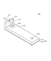
- FIG. 1 is a perspective view of a fluid handling device according to the first embodiment of the present invention.
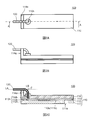
- 2A is a plan view of the fluid handling device shown in FIG. 1
- FIG. 2B is a front view of the fluid handling device
- FIG. 2C is a cross-sectional view taken along the line AA in FIG. 2A.
- FIG. 3 is a cross-sectional view of the fluid handling device according to the modified example of the first embodiment.
- FIG. 4A is a perspective view of the fluid handling device according to a further modification of the first embodiment
- FIG. 4B is a front view of the fluid handling device shown in FIG. 4A.
- FIG. 5A is a perspective view of the fluid handling device according to a further modification of the first embodiment
- FIG. 5B is a cross-sectional view of the fluid handling device shown in FIG. 5A.
- FIG. 6 is a perspective view of the fluid handling device according to the second embodiment of the present invention.
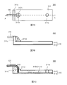
- 7A is a plan view of the fluid handling device shown in FIG. 6,
- FIG. 7B is a front view of the fluid handling device, and
- FIG. 7C is a cross-sectional view taken along the line AA in FIG. 7A.
- FIG. 8A is a perspective view of the fluid handling device according to the modified example of the second embodiment, and
- FIG. 8B is a cross-sectional view of the fluid handling device shown in FIG. 8A.
- the fluid handling device of the present invention has a first device for flowing a fluid and a tube having a first end connected to a flow path of the first device.
- a second device such as a detection device or a reaction device
- the fluid in the first device can be supplied to the second device, or a second device can be used. It becomes possible to receive the fluid in the device to the first device side.
- the case where the fluid in the first device is supplied to the second device will be described as an example, but the present invention is not limited to this aspect.
- the fluid referred to in the present specification is a gas, a liquid, or the like having fluidity, and may contain a single component or a plurality of components, and the fluid is in a solvent.
- a solid component may be dispersed therein.
- droplets or the like that are incompatible with the solvent may be dispersed in the solvent.
- FIG. 1 shows a perspective view of the fluid handling device 100 of the first embodiment.
- FIG. 2A shows a plan view of the fluid handling device 100
- FIG. 2B shows a front view of the fluid handling device 100
- FIG. 2C shows a cross-sectional view taken along the line AA in FIG. 2A.
- these figures schematically show an example of the structure of the fluid handling device 100 of the present embodiment, and the fluid handling device 100 is not limited to the structure.
- the fluid handling device 100 of the present embodiment has a first device 110 and a tube 120, and the first end portion of the tube 120 has an opening 110h of the first device 110. It has been inserted.
- the second end side of the tube 120 is fixed by the support 114a of the first device 110.
- the first device 110 of the present embodiment has a structure in which the first substrate 111, the film 112, the adhesive layer 113, and the second substrate 114 are laminated in this order. Further, as shown in FIG. 2C, the first device 110 of the present embodiment has an introduction port 111a for introducing a fluid, a flow path 110b for communicating with the introduction port 111a and allowing the fluid to flow. It has an opening 110h that communicates with the flow path 110b and the outside, and a support portion 114a that supports the second end side of the tube 120.
- the introduction port 111a for introducing the fluid into the first device 110 is arranged on the first substrate 111 side.
- the position of the introduction port 111a is not limited to the first substrate 111 side, and may be arranged on the second substrate 114 side.
- the introduction port 111a is opened in a columnar shape, but the introduction port 111a may have a structure suitable for the shape of a syringe, a tube, or the like for introducing a fluid.
- the first device 110 may have only one introduction port 111a, or may have two or more introduction ports 111a.
- the flow path 110b for flowing the fluid is composed of a groove 111b provided on the first substrate 111 and a region surrounded by the film 112.
- the flow path 110b may connect the introduction port 111a and the opening 110h, and allow the fluid to flow from the introduction port 111a side to the opening 110h side.
- FIG. 2C shows a flow path 110b that linearly connects the introduction port 111a and the opening 110h, but the structure of the flow path 110b is not limited to a straight line and may be branched in the middle.
- the first device 110 may have a plurality of flow paths 110b, and has a chamber (not shown) or the like for temporarily accommodating the fluid between the flow paths 110b. May be good.
- the chamber can be a region surrounded by the recess provided in the first substrate 111 and the film 112.
- various treatments on the fluid such as observing the fluid in the chamber and reacting the components in the fluid with a reagent or the like. ..
- the width and depth of the flow path 110b and the chamber are appropriately selected according to the type of fluid, the flow rate, and the like.
- the width and depth of the flow path 110b and the chamber may be uniform or may change from the introduction port 111a side to the opening 110h side.
- the opening 110h only needs to be able to communicate with the outside of the flow path 100b and the first device 110, and the through holes 112h and 113h provided in the film 112, the adhesive layer 113, and the second substrate 114, respectively. , 114h.
- a plurality of openings 110h may be arranged in the first device 110.
- the shape of the opening 110h is appropriately selected according to the diameter and shape of the first end of the tube 120 to be inserted into the opening 110h.
- the opening diameter of the opening 110h may be constant from the second substrate 114 side to the film 112 side, or may change continuously or stepwise.
- the tube 120 When inserting the first end of the tube 120 into the opening 110h, the tube 120 may be inserted into the through hole 112h of the film 112, but as shown in FIG. 2C, a part of the opening 110h ( In the present embodiment, the tube 120 may be inserted only into the through hole 114h) of the second substrate 114.
- the side wall of the opening 110h and the outer peripheral surface of the tube 120 are preferably in close contact with each other.
- the opening diameter of the tube 120 is preferably equal to or less than the outer diameter of the tube 120.
- the first device 110 may have a structure for holding the shape of the tube 120 inserted into the opening 110h and fixing the position of the tube 120.
- a cylindrical holding portion 114b arranged so as to surround the opening end of the opening 110h is arranged on the second substrate 114.
- the holding portion 114b is arranged on the second substrate 114, deformation and crushing of the tube 120 in the vicinity of the opening 110h are suppressed.
- the holding portion 114b is arranged, the contact area between the wall surface of the opening 110h and the outer peripheral surface of the tube 120 becomes large, so that the tube 120 is less likely to fall off from the opening 110h.
- the support portion 114a for supporting the second end side of the tube 120 is arranged on the second substrate 114.
- the support portion 114a is a central axis of the first end portion of the tube 120 fixed to the above-mentioned opening 110h (LB in FIG. 2C) and a side of the tube 120 connected to the second device (second end portion). ) (LA in FIG. 2C) and the second end side of the tube 120 are fixed so as to have an angle.
- having an angle means forming an angle whose absolute value is smaller than 180 °. In the present embodiment, as shown in FIG.
- the angle ⁇ formed by the central axis LB of the first end of the tube 120 and the central axis LB of the second end of the tube 120 is approximately 90 °. However, it is not limited to the angle. However, the absolute value of ⁇ is usually preferably about 0 to 175 °, more preferably about 0 to 120 °.
- only one support portion 114a is arranged in the first device 110, but two or more support parts 114a may be arranged in the first device 110.
- a plurality of support portions 114a may be arranged along the tube 120 so that one tube 120 is supported by a plurality of support portions 114a.
- the support portions 114a may be arranged so as to support each tube 120.
- the position of the support portion 114a may be a position that does not hinder the connection between the second device and the tube 120, but is preferably arranged in a region close to the second end portion of the tube 120.
- the support 114a is arranged along the outer edge of the first device 110.
- the shape of the support portion 114a may be such that the second end portion of the tube 120 can be fixed at a desired height and orientation.
- the support portion 114a of the present embodiment is a rectangular parallelepiped region projecting in a direction substantially perpendicular to the joint surface between the second substrate 114 and the adhesive layer 113.
- a U-shaped notch (groove) 1141 for fixing the second end side of the tube 120 is formed on the upper portion of the support portion 114a. By fitting the tube 120 into the notch 1141, the position of the second end of the tube 120 is fixed.
- the shape of the support portion 114a is not limited to the shape.
- the shape of the notch (groove) 1141 of the support portion 114a is U-shaped, but the shape of the notch 1141 can fix the end portion of the tube 120 and the tube.
- the shape may be any shape that does not block the 120, and may be, for example, a semicircular shape or a V shape.
- the depth of the notch is preferably deeper than the outer diameter of the tube 120. If the depth of the notch 1141 is sufficiently deep, the tube 120 does not protrude above the top surface of the support portion 114a, and the tube 120 fixed to the support portion 114a interferes with other members to block or position. It is possible to prevent it from shifting.
- the width of the notch (groove) 1141 is the same as the outer diameter of the tube 120 or slightly smaller than the outer diameter of the tube. As a result, the second end side of the tube 120 is fitted in the notch, and the position of the second end of the tube 120 is easily fixed.
- the first substrate 111 in the first device 110 may have a through hole forming the introduction port 111a and a groove 111b forming a part of the inner wall of the flow path. ..
- materials constituting the first substrate 111 include polyesters such as polyethylene terephthalate; polycarbonate; acrylic resins such as polymethylmethacrylate; polyvinyl chlorides; polyolefins such as polyethylene, polypropylene, and cycloolefin resins; polyethers; Polystyrene; silicone resin; and resin materials such as various elastomers are included.
- the first substrate 111 can be molded by, for example, injection molding.
- the first substrate 111 may have light transmission and may not have light transmission. For example, when observing the fluid from the first substrate 111 side after introducing the fluid into the fluid handling device 100, it is preferable to select the material so that the first substrate 111 has light transmission.
- the film 112 in the first device 110 may be a film capable of covering the introduction port 111a and the groove 111b of the first substrate 111 and the periphery thereof and having the through hole 112h. ..
- the film 112 is arranged so as to cover substantially the entire surface of one surface of the first substrate 111, but may cover only a part of the region of the first substrate 111.
- the film 112 may be a film made of a material that is not eroded by the fluid introduced into the fluid handling device 100, and its thickness and the like are appropriately selected.
- materials constituting the film 112 include polyesters such as polyethylene terephthalate; polycarbonate; acrylic resins such as polymethylmethacrylate; polyvinyl chlorides; polyolefins such as polyethylene, polypropylene, and cycloolefin resins; polyethers; polystyrene; silicones. Resin; and resin materials such as various elastomers are included.
- the film 112 and the first substrate 111 are joined, for example, they are joined by fusion splicing or an adhesive.
- the adhesive layer 113 in the first device 110 may be a layer capable of joining the film 112 and the second substrate 114 described later and having a through hole 113h in a desired region.
- the adhesive layer 113 is arranged almost entirely between the film 112 and the second substrate 114, but may be arranged only in a part of the region.
- the adhesive layer 113 may be made of an elastic material.
- the adhesive layer 113 has elasticity, when the first end portion of the tube 120 is inserted into the through hole 113h of the adhesive layer 113, the adhesive layer 113 easily adheres to the outer periphery of the tube 120, and the first device 110 It is possible to suppress the leakage of fluid from the gap between the opening 110h and the tube 120.
- the adhesive layer 113 may be a layer made of a self-supporting sheet, and may be, for example, a film obtained by applying an adhesive to at least one of the film 112 and the second substrate 114.
- the thickness of the adhesive layer 113 is not particularly limited as long as the film 112 and the second substrate 114 can be sufficiently adhered to each other, and is appropriately selected according to the type of the adhesive layer 113, the required adhesive strength, and the like. ..
- the type of the adhesive layer 113 is not particularly limited, and a layer made of a known adhesive can be used.
- adhesives examples include vinyl acetate resin; ethylene vinyl acetate resin; epoxy resin; cyanoacrylate resin; acrylic resin; chloroprene rubber, styrene butadiene rubber, fluororubber, silicone rubber, nitrile rubber, ethylene rubber, butylene rubber and other rubbers; Fluororesin such as polytetrafluoroethylene, polychlorotrifluoroethylene, polyvinylidene fluoride, polyvinyl fluoride; and the like are included.
- the second substrate 114 in the first device 110 is a plate-shaped member arranged on the adhesive layer 113, and has the support portion 114a and the holding portion 114b on the surface opposite to the adhesive layer 113. I just need to be there.
- the surface of the second substrate 114 facing the adhesive layer 113 may be flat or uneven. Further, the second substrate 114 may cover the entire surface of the first substrate 111 or the film 112, or may cover only a part of the region.
- the material of the second substrate 114 can be the same as the material of the first substrate 111. Further, the second substrate 114 may be integrally molded by injection molding or the like, and a flat plate-shaped member, a support portion 114a, and a holding portion 114b are separately manufactured and bonded together. It may be.
- the tube 120 may be a tubular member that can be connected to the opening 110h of the first device 110 and the connection port of the second device described above, and may have flexibility. It is not necessary to have. Further, the material is not particularly limited as long as it is a material that is not eroded by a fluid, and may be made of metal or resin.
- the inner diameter of the tube is appropriately selected according to the type of fluid and the like.
- the outer diameter of the tube 120 is appropriately selected according to the application of the fluid handling device, the desired strength of the tube 120, and the like.
- the inner and outer diameters of the tube 120 are uniform from the first end inserted into the opening 110h of the first device 110 to the second end side connected to the second device. May be different.
- the tube 120 is configured to be removable from the opening 110h of the first device 110, but the tube 120 may be joined to the opening 110h of the first device 110. ..
- the first end portion of the tube 120 of the fluid handling device 100 is inserted into the opening 110h of the first device 110.
- the second end side of the tube 120 is fitted into the notch 1141 of the support portion 114a of the first device 110, and the tube 120 is fixed at two points.
- the fluid handling device 100 is then placed in the vicinity of the desired second device (not shown) to connect the second end of the tube 120 to the connection port of the second device.
- the desired fluid is introduced from the introduction port 111a of the first device 110 and flows in the flow path 110b. At this time, the fluid may be observed if necessary. Further, the fluid flowing in the first device 110 may be sorted and only the desired fluid may be moved to the flow path 110b connected to the opening 110h (tube 120).
- the fluid that has reached the vicinity of the opening 110h of the first device 110 is moved to the second device side via the tube 120.
- the fluid may be sucked from the device side, or pressure may be applied from the introduction port 111a side of the fluid handling device 100 to push out the fluid.
- the first end of the tube (the end connected to the first device 110) is on the upper side in the direction of gravity
- the second end of the tube (the end connected to the second device) is on the lower side in the direction of gravity.
- the orientation of the fluid handling device 100 may be adjusted so as to be. In this case, gravity makes it easier for the fluid to move within the tube 120 and makes it easier for the fluid to move to the second device.
- FIG. 3 is a cross-sectional view of the fluid handling device 1100 according to the modified example of the present embodiment. Further, since the fluid handling device 1100 shown in FIG. 3 is the same as the above-mentioned fluid handling device 100 except for the sealing member 130, the same members are designated by the same reference numerals, and detailed description thereof will be omitted here. To do.
- a tubular sealing member 130 is fitted into the opening 110h, and the tube 120 is inserted into the sealing member 130 to seal between the sealing member 130 and the tube 120 and to seal the tube 120.
- a gap is less likely to occur between the stop member 130 and the wall surface of the opening 110h, the first end of the tube 120 is less likely to come out of the opening 110h (sealing member 130), and fluid leakage is suppressed. ..
- the opening diameter of the opening 110h is set to be slightly smaller than the outer diameter of the sealing member 130.
- Examples of the material constituting such a sealing member 130 include the same material as the resin or the like constituting the adhesive layer 113 described above.
- the shape of the support portion 114a included in the second substrate 114 of the above-mentioned fluid handling device 100 is not limited to a substantially rectangular parallelepiped shape, and as shown in FIGS. 4A and 4B, for example, the second substrate 214 and the adhesive layer 113 A plate-shaped portion 2142 protruding in a direction substantially perpendicular to the adhesive surface of the fluid handling device, and a protruding portion 2143 protruding from the plate-shaped portion 2142 to the radial outside (second end side of the tube 120) of the fluid handling device 1200. , May be composed of.
- the plate-shaped portion 2142 and the protruding portion 2143 are provided with a groove-shaped notch 2141 into which the tube 120 can be fitted.
- FIG. 4A is a perspective view of the fluid handling device 1200 according to a modified example of the present embodiment
- FIG. 4B is a front view of the fluid handling device 1200.
- the fluid handling device 1200 shown in FIGS. 4A and 4B is the same as the above-mentioned fluid handling device 100 except for the shape of the support portion 214a of the second substrate 214 of the first device 210. Have the same reference numerals, and detailed description thereof will be omitted here.
- the contact area between the support portion 214a and the tube 120 can be increased, and the second end portion of the tube 120 becomes more difficult to move.
- the shape of the notch 2141 (groove) of the support portion 214a is U-shaped, but the shape of the notch is not limited to the shape.
- FIGS. 5A and 5B the fluid handling device 1500 according to a further modification of the present embodiment is shown in FIGS. 5A and 5B.
- FIG. 5A is a perspective view of the fluid handling device 1500 according to the modified example
- FIG. 5B is a cross-sectional view of the fluid handling device 1500.
- the fluid handling device 1500 shown in FIGS. 5A and 5B is the same as the above-mentioned fluid handling device 100 except for the shape of the support portion 514a of the second substrate 514 of the first device 510. Have the same reference numerals, and detailed description thereof will be omitted here.
- the support portion 514a of the second substrate 514 has a second through hole 5141.
- the diameter of the second through hole 5141 is preferably the same as or slightly smaller than the outer diameter of the tube 120.
- the above-mentioned fluid handling device 100 may further have a stopper (not shown) or the like for fixing the support portion 114a and the tube 120.
- the stopper can be an annular member that is fixed at one or more locations on the outer circumference of the tube 120 and projects radially outward of the tube 120. In this case, the movement of the tube 120 is suppressed by the contact between the support portion 114a and the stopper.
- an elastic body (not shown) or the like may be arranged on the inner circumference of the notch 1141 of the support portion 114a.
- an elastic body is arranged on the inner circumference of the notch 1141, a frictional force is generated between the tube 120 and the elastic body, so that the position of the tube 120 is less likely to shift.
- FIG. 6 shows a perspective view of the fluid handling device 300 of the second embodiment.
- FIG. 7A shows a plan view of the fluid handling device 300
- FIG. 7B shows a side view of the fluid handling device 300
- FIG. 7C shows a cross-sectional view taken along the line AA in FIG. 7A.
- these figures schematically show an example of the structure of the fluid handling device 300 of the present embodiment, and the fluid handling device 300 is not limited to the structure.
- the fluid handling device 300 of the second embodiment has a first device 310 and a tube 120.
- the first end of the tube 120 is fixed by the opening 310h of the first device 310, and the second end of the tube 120 is the support of the first device 110. It is fixed by 311c.
- the tube 120 of the fluid handling device 300 of the present embodiment is the same as the tube 120 of the fluid handling device 100 of the first embodiment described above. Therefore, only the first device 310 will be described below.
- the first device 310 of the present embodiment has a structure in which the main body portion 311 and the film 312 are laminated. Further, the first device 310 of the present embodiment communicates with the introduction port 311a for introducing the fluid, the introduction port 311a, and the flow path 310b for flowing the fluid, the flow path 310b, and the outside. It has an opening 310h for communication and a support 311c for supporting the second end side of the tube 120.
- the introduction port 311a for introducing the fluid is arranged in the main body 311.
- the introduction port 311a may be arranged on the film 312 side.
- the first device 310 may have only one introduction port 311a or may have two or more introduction ports 311a.
- the flow path 310b for flowing the fluid is composed of a region surrounded by the groove 311b provided in the main body 311 and the film 312.
- the flow path 310b may connect the introduction port 311a and the opening 310h, and allow the fluid to flow from the introduction port 311a side to the opening 310h side.
- FIG. 7C shows a flow path 310b that linearly connects the introduction port 311a and the opening 310h, but the structure of the flow path 310b is not limited to a straight line and may be branched in the middle.
- the first device 310 may have a plurality of flow paths 310b, and has a chamber (not shown) or the like for temporarily accommodating the fluid between the flow paths 310b. May be good.
- the shape of the flow path 310b and the chamber can be the same as the shape of the flow path 110b and the chamber of the first device 110 of the first embodiment.
- the opening 310h into which the first end of the tube 120 is inserted is composed of a through hole provided in the main body 311.
- the first device 310 of the present embodiment has only one opening 310h, but the first device 310 may have a plurality of openings 310h.
- the shape of the opening 310h can be the same as the shape of the opening 110h of the first device 310 of the first embodiment.
- the first device 310 may have a structure for holding the shape of the tube 120 inserted into the opening 310h and fixing the position of the tube 120.
- the holding portion 311d arranged so as to surround the opening end of the opening portion 310h is arranged in the main body portion 311.
- the holding portion 311d supports the outer peripheral surface of the tube 120, and the deformation and crushing of the tube 120 are suppressed. Further, since the contact area between the opening 310h and the outer peripheral surface of the tube 120 becomes large, the tube 120 is less likely to fall off from the opening 310h.
- the support portion 311c that supports the second end side of the tube 120 is connected to the central axis of the first end portion of the tube 120 fixed to the above-mentioned opening 310h and the second device of the tube 120.
- the configuration may be such that the second end side of the tube 120 is fixed so as to have an angle with the central axis of the second end portion.
- the first device 310 has only one support 311c, but the first device 310 may have two or more support 311c.
- a plurality of support portions 311c may be arranged along the tube 120 so that one tube 120 is supported by a plurality of support portions 311c.
- the support portions 311c may be arranged so as to support each tube 120.
- the position of the support portion 311c is not particularly limited as long as it does not interfere with the connection between the second device and the tube 120, but is arranged in a region close to the second end portion of the tube 120. Is preferable.
- the support 311c is arranged along the outer edge of the first device 310.
- the shape of the support portion 311c may be such that the second end portion of the tube 120 can be fixed at a desired height and orientation.
- the support portion 311c of the present embodiment is a rectangular parallelepiped region projecting in a direction substantially perpendicular to the joint surface between the main body portion 311 and the film 312.
- a U-shaped notch (groove) 3111 for fixing the tube 120 is formed on the upper portion of the support portion 311c. By fitting the tube 120 into the notch 3111, the position of the second end of the tube 120 is fixed.
- the shape of the support portion 311c is not limited to the shape.
- the material constituting the main body 311 is the same as the material constituting the first substrate 111 of the first embodiment described above.
- the main body portion 311 may have light transmission property and may not have light transmission property. For example, when observing a fluid from the main body 311 side of the fluid handling device 300, it is preferable to select a material so that the main body 311 has light transmission.
- the film 312 may be any film that can cover the groove 311b of the main body portion 311 described above.
- the film 312 is arranged so as to cover substantially the entire surface of one surface of the main body portion 311.
- the film 312 may be arranged so as to cover only a part of the main body portion 311.
- the film 312 is made of the same material as the film 112 of the first embodiment described above.
- the film 312 may or may not have light transmission.
- the film 312 does not have to have light transmission.
- the first end portion of the tube 120 of the fluid handling device 300 is inserted into the opening 310h of the first device 310.
- the second end side of the tube 120 is fitted into the notch 3111 of the support portion 311c of the first device 310, and the tube 120 is fixed at two points.
- the fluid handling device 300 is then placed in the vicinity of the desired second device (not shown) to connect the second end of the tube 120 to the connection port of the second device.
- the desired fluid is introduced from the introduction port 311a of the first device 310 and flows in the flow path 310b. At this time, the fluid may be observed if necessary. Further, the fluid flowing in the first device 310 may be sorted and only the desired fluid may be moved to the flow path 310b connected to the opening 310h (tube 120).
- the fluid that has reached the vicinity of the opening 310h of the first device 310 is moved to the device side via the tube 120.
- the fluid may be sucked from the device side, or the fluid may be pushed out by applying pressure from the introduction port 311a side of the fluid handling device 300.
- the first end of the tube (the end connected to the first device 310) is on the upper side in the direction of gravity
- the second end of the tube (the end connected to the second device) is on the lower side in the direction of gravity.
- the orientation of the fluid handling device 300 may be adjusted so as to be. In this case, gravity makes it easier for the fluid to move within the tube 120 and makes it easier for the fluid to move to the second device.
- an elastic tubular sealing member (not shown) may be arranged in place of the holding portion 311d of the main body portion 311.
- the tubular sealing member By fitting the tubular sealing member into the opening 310h and inserting the tube 120 inside the sealing member, the space between the sealing member and the tube 120 and the wall surface between the sealing member and the opening 310h It becomes difficult for a gap to be formed in the tube 120, the tube 120 becomes difficult to come off, and the leakage of fluid is suppressed.
- the opening diameter of the opening 310h is preferably set to be slightly smaller than the outer diameter of the sealing member.
- the sealing member can be the same as that described in the first embodiment described above.
- the shape of the support portion 311c described above is not limited to the shape described above, and for example, the shape of the main body portion 311 of the present embodiment may have the same structure as the second substrate 214 of the first device shown in FIG. 4A. That is, as shown in FIG. 4, the support portion 311c is radially outside (the second end side of the tube 120) of the fluid handling device (1200 in FIG. 4) from the plate-shaped portion 2142 and the plate-shaped portion 2142. ) May have a shape having a protruding portion 2143.
- FIGS. 8A and 8B The fluid handling device 1600 according to a further modification of this embodiment is shown in FIGS. 8A and 8B.
- FIG. 8A is a perspective view of the fluid handling device 1600 according to the modified example
- FIG. 6B is a cross-sectional view of the fluid handling device 1600.
- the fluid handling device 1600 shown in FIGS. 6A and 6B is the same as the above-mentioned fluid handling device 300 except for the shape of the support portion 611c of the main body portion 611 of the first device 610.
- the same members are designated by the same reference numerals, and detailed description thereof will be omitted here.
- the support portion 611c of the main body portion 611 has a second through hole 6111.
- the diameter of the second through hole 6111 is preferably the same as or slightly smaller than the outer diameter of the tube 120.
- the above-mentioned fluid handling device 100 may further have a stopper (not shown) for fixing the support portion 311c and the tube 120, and an elastic body is formed on the inner circumference of the notch of the support portion 311c. (Not shown) and the like may be arranged.
- the tube is fixed at two points by the first device, so that the connection with the second device is easy.
- the tube is difficult to move, so that the tube is caught by another member and damaged, or comes out of the first device or the second device, and the tube is a detection device. There is little interference with such things.
- the fluid handling device of the present invention can be easily and accurately connected to various devices. Therefore, it is particularly useful as a microfluidic handling device or the like used for various inspections and analyzes.
Landscapes
- Chemical & Material Sciences (AREA)
- Health & Medical Sciences (AREA)
- Analytical Chemistry (AREA)
- General Health & Medical Sciences (AREA)
- Hematology (AREA)
- Clinical Laboratory Science (AREA)
- Chemical Kinetics & Catalysis (AREA)
- Dispersion Chemistry (AREA)
- Physical Or Chemical Processes And Apparatus (AREA)
- Automatic Analysis And Handling Materials Therefor (AREA)
Abstract
各種装置と確実かつ容易に接続可能であり、所望の流体を各種装置に供給したり、流体を各種装置から受け取ったりすることが可能な流体取扱装置を提供することを課題とする。上記課題を解決する流体取扱装置は、流体を流動させるための流路、ならびに前記流路および外部を連通する開口部を有する第1のデバイスと、前記開口部に第1の端部が挿入されたチューブと、を有する。前記第1のデバイスは、前記チューブの第2の端部の中心軸が前記チューブの第1の端部の中心軸に対して角度を有するように前記チューブを固定する支持部をさらに有する。
Description
本発明は、流体取扱装置に関する。
近年、タンパク質や核酸等の微量な物質の分析や反応等を高精度かつ高速に行うために、微細な流路を有する流体取扱装置が使用されている。流体取扱装置は、分析に必要な試薬および試料の量が少なくてもよいという利点を有しており、臨床検査や食物検査、環境検査等の様々な用途での使用が期待されている。
ここで、流体取扱装置から特定の物質のみを回収したり、流体取扱装置内の物質を取り出して他の分析や反応に供したりするため、流体取扱装置と他の装置とを接続することがある。例えば、特許文献1には、流路基板に可撓性を有するチューブの一方の端部が挿入された流体取扱装置が記載されている(特許文献1)。当該流体取扱装置では、チューブの他方の端部を他の装置に接続することで、流路基板内の流体を、各種装置側に供給することができる。
しかしながら、特許文献1のように、流路基板にチューブの一方の端部を固定しただけでは、チューブの向きや高さが定まらず、各種装置と精度よく位置合わせすることが難しい。また、チューブや接続口が複数ある場合には、取り付け間違い等が生じることもある。さらに、流路基板と各種装置とを接続した後にも、チューブの位置が定まり難く、チューブが流路基板や他の装置から抜けたり、チューブが他の装置と干渉したりすることもある。
本発明は、各種装置と確実かつ容易に接続可能であり、流体を各種装置に供給したり、流体を各種装置から受け取ったりすることが可能な流体取扱装置の提供を目的とする。
本発明は、以下の流体取扱装置を提供する。
流体を流動させるための流路、ならびに前記流路および外部を連通する開口部を有する第1のデバイスと、前記開口部に第1の端部が挿入されたチューブと、を有し、前記第1のデバイスは、前記チューブの第2の端部の中心軸が前記チューブの第1の端部の中心軸に対して角度を有するように前記チューブを固定する支持部をさらに有する、流体取扱装置。
流体を流動させるための流路、ならびに前記流路および外部を連通する開口部を有する第1のデバイスと、前記開口部に第1の端部が挿入されたチューブと、を有し、前記第1のデバイスは、前記チューブの第2の端部の中心軸が前記チューブの第1の端部の中心軸に対して角度を有するように前記チューブを固定する支持部をさらに有する、流体取扱装置。
本発明の流体取扱装置によれば、チューブを介して各種装置と確実かつ容易に接続可能であり、流体を各種装置に供給したり、流体を各種装置から受け取ったりすることが可能である。
本発明の流体取扱装置は、流体を流動させるための第1のデバイスと、当該第1のデバイスの流路に第1の端部が接続されたチューブと、を有する。当該流体取扱装置のチューブの第2の端部を、検出装置や反応装置等の第2のデバイスに接続することで、第1のデバイス中の流体を第2のデバイスに供給したり、第2のデバイス中の流体を第1のデバイス側に受け取ったりすることが可能となる。なお、以下の説明では、第1のデバイス中の流体を、第2のデバイスに供給する場合を例に説明するが、本発明は、当該態様に制限されない。
なお、本明細書でいう、流体とは、流動性を有する気体や液体等であり、単一の成分を含んでいてもよく、複数の成分を含んでいてもよい、また流体は、溶媒中に固体状の成分が分散されたもの等であってもよい。さらに、溶媒中に、当該溶媒と相溶しないドロップレット(液滴)等が分散されたものであってもよい。以下、本発明の流体取扱装置について、図面を用いて詳しく説明する。
(第1の実施形態)
図1に第1の実施形態の流体取扱装置100の斜視図を示す。また、図2Aに当該流体取扱装置100の平面図を示し、図2Bに当該流体取扱装置100の正面図を示し、図2Cに、図2AにおけるA-A線での断面図を示す。ただし、これらの図は、本実施形態の流体取扱装置100の構造の一例を模式的に示したものであり、流体取扱装置100は、当該構造に限定されない。
図1に第1の実施形態の流体取扱装置100の斜視図を示す。また、図2Aに当該流体取扱装置100の平面図を示し、図2Bに当該流体取扱装置100の正面図を示し、図2Cに、図2AにおけるA-A線での断面図を示す。ただし、これらの図は、本実施形態の流体取扱装置100の構造の一例を模式的に示したものであり、流体取扱装置100は、当該構造に限定されない。
図1に示すように、本実施形態の流体取扱装置100は、第1のデバイス110と、チューブ120とを有し、チューブ120の第1の端部が第1のデバイス110の開口部110hに挿入されている。一方、チューブ120の第2の端部側は、第1のデバイス110の支持部114aによって固定されている。
・第1のデバイス
本実施形態の第1のデバイス110は、第1基板111と、フィルム112と、接着層113と、第2基板114とがこの順に積層された構造を有する。また、本実施形態の第1のデバイス110は、図2Cに示すように、流体を導入するための導入口111aと、当該導入口111aに連通し、流体を流動させるための流路110bと、当該流路110bおよび外部を連通する開口部110hと、チューブ120の第2の端部側を支持する支持部114aと、を有する。
本実施形態の第1のデバイス110は、第1基板111と、フィルム112と、接着層113と、第2基板114とがこの順に積層された構造を有する。また、本実施形態の第1のデバイス110は、図2Cに示すように、流体を導入するための導入口111aと、当該導入口111aに連通し、流体を流動させるための流路110bと、当該流路110bおよび外部を連通する開口部110hと、チューブ120の第2の端部側を支持する支持部114aと、を有する。
本実施形態では、流体を第1のデバイス110に導入するための導入口111aが第1基板111側に配置されている。ただし、導入口111aの位置は第1基板111側に限定されず、第2基板114側に配置されていてもよい。また、本実施形態では、導入口111aが、円柱状に開口しているが、導入口111aは、流体を導入するためのシリンジやチューブ等の形状に合わせた構造を有していてもよい。また、第1のデバイス110は、導入口111aを1つのみ有していてもよく、2つ以上有していてもよい。
流体を流動させるための流路110bは、第1基板111に設けられた溝111bと、フィルム112とに囲まれた領域から構成される。流路110bは、導入口111aと開口部110hとを繋ぎ、導入口111a側から開口部110h側に流体を流動させることが可能であればよい。図2Cには、導入口111aおよび開口部110hを直線状に繋ぐ流路110bを示しているが、流路110bの構造は直線状に限定されず、途中で分岐していてもよい。さらに、第1のデバイス110は、流路110bを複数有していてもよく、流路110bどうしの間に、流体を一次的に収容するためのチャンバー(図示せず)等を有していてもよい。チャンバーは、第1基板111に設けられた凹部とフィルム112とに囲まれた領域とすることができる。第1のデバイス110にチャンバーが配置されていると、チャンバー内で流体を観察したり、流体中の成分を試薬等と反応させたりする等、流体に対して各種処理を行うことが可能となる。
なお、流路110bやチャンバーの幅や深さは、流体の種類や流量等に応じて適宜選択される。例えば、導入口111a側から開口部110h側にかけて、流路110bやチャンバーの幅や深さが均一であってもよく、変化していてもよい。
一方、上記開口部110hは、上記流路100bおよび第1のデバイス110の外部を連通可能でればよく、フィルム112、接着層113、および第2基板114にそれぞれ設けられた貫通孔112h、113h、114hから構成される。本実施形態の第1のデバイス110には、開口部110hが1つのみ配置されているが、第1のデバイス110には、複数の開口部110hが配置されていてもよい。
当該開口部110hの形状は、当該開口部110hに挿入するチューブ120の第1の端部の径や形状等に応じて適宜選択される。開口部110hの開口径は、第2基板114側からフィルム112側にかけて一定であってもよく、連続的または段階的に変化していてもよい。チューブ120の第1の端部を開口部110hに挿入する際、フィルム112の貫通孔112h内まで、チューブ120を挿入してもよいが、図2Cに示すように、開口部110hの一部(本実施形態では、第2基板114の貫通孔114h)にのみチューブ120を挿入してもよい。
なお、開口部110hにチューブ120を挿入した際、開口部110hの側壁およびチューブ120の外周面は密着することが好ましく、本実施形態の第1のデバイス110では、第2基板114の貫通孔114hの開口径が、チューブ120の外径以下であることが好ましい。
ここで、第1のデバイス110は、開口部110hに挿入したチューブ120の形状を保持したり、チューブ120の位置を固定したりするための構造を有していてもよい。本実施形態では、第2基板114に、開口部110hの開口端を囲むように配置された円筒状の保持部114bが配置されている。第2基板114に保持部114bが配置されていると、開口部110h近傍でのチューブ120の変形やつぶれが抑制される。また保持部114bが配置されていると、開口部110hの壁面とチューブ120の外周面との接触面積が大きくなるため、チューブ120が開口部110hから脱落し難くなる。
一方、チューブ120の第2の端部側を支持するための支持部114aは、第2基板114に配置されている。支持部114aは、上述の開口部110hに固定されたチューブ120の第1の端部の中心軸(図2CにおけるLB)と、チューブ120の第2のデバイスと接続する側(第2の端部)の中心軸(図2CにおけるLA)と、が角度を有するようにチューブ120の第2の端部側を固定する。なお、本明細書において、角度を有するとは、絶対値が180°より小さい角度を構成することをいう。本実施形態では、図2Cに示すように、チューブ120の第1の端部の中心軸LBと、チューブ120の第2の端部の中心軸LBとのなす角度θが、略90°であるが、当該角度に制限されない。ただし、通常θの絶対値は0~175°程度であることが好ましく、0~120°程度がより好ましい。
なお、本実施形態では、第1のデバイス110に支持部114aが一つのみ配置されているが、第1のデバイス110に支持部114aが二つ以上配置されていてもよい。例えば、一つのチューブ120を複数の支持部114aで支持するように、複数の支持部114aがチューブ120に沿って配置されていてもよい。また、開口部110hおよびチューブ120がそれぞれ複数ある場合には、各チューブ120を支えるように、支持部114aがそれぞれ配置されていてもよい。
ここで、支持部114aの位置は、第2のデバイスとチューブ120との接続を阻害しない位置であればよいが、チューブ120の第2の端部に近い領域に配置されていることが好ましい。本実施形態では、支持部114aが第1のデバイス110の外縁に沿って配置されている。
支持部114aの形状は、チューブ120の第2の端部を所望の高さおよび向きで固定可能であればよい。本実施形態の支持部114aは、第2基板114と接着層113との接合面に略垂直な方向に突出する直方体状の領域である。当該支持部114aの上部には、チューブ120の第2の端部側を固定するためのU字状の切り欠き(溝)1141が形成されている。当該切り欠き1141にチューブ120を嵌め込むことで、チューブ120の第2の端部の位置が固定される。ただし、支持部114aの形状は当該形状に制限されない。
ここで、本実施形態では、支持部114aが有する切り欠き(溝)1141の形状をU字状としているが、当該切り欠き1141の形状は、チューブ120の端部を固定可能であり、かつチューブ120を閉塞させない形状であればよく、例えば半円状やV字状等であってもよい。ただし、切り欠きの深さは、チューブ120の外径より深いことが好ましい。切り欠き1141の深さが十分に深いと、支持部114aの天面より上にチューブ120が突出せず、支持部114aに固定されたチューブ120が他の部材と干渉して閉塞したり、位置がずれたりすることを防ぐことができる。
また、切り欠き(溝)1141の幅は、チューブ120の外径と同一、またはチューブの外径より若干小さいことが好ましい。これにより、チューブ120の第2の端部側が切り欠き内に嵌まり、チューブ120の第2の端部の位置が固定されやすくなる。
ここで、上記第1のデバイス110における第1基板111は、上述の導入口111aを構成する貫通孔と、上述の流路の内壁の一部を構成する溝111bとを有していればよい。当該第1基板111を構成する材料の例には、ポリエチレンテレフタレート等のポリエステル;ポリカーボネート;ポリメタクリル酸メチル等のアクリル樹脂;ポリ塩化ビニル;ポリエチレン、ポリプロピレン、およびシクロオレフィン樹脂等のポリオレフィン;ポリエーテル;ポリスチレン;シリコーン樹脂;ならびに各種エラストマー等の樹脂材料等が含まれる。また、上記第1基板111は、例えば射出成形等により成形することができる。
なお、第1基板111は、光透過性を有していてもよく、光透過性を有さなくてもよい。例えば、流体取扱装置100に流体を導入後、第1基板111側から流体を観察する場合等には、第1基板111が光透過性を有するように、材料を選択することが好ましい。
また、上記第1のデバイス110におけるフィルム112は、上述の第1基板111の導入口111aおよび溝111b、ならびにその周囲を覆うことが可能であり、かつ上記貫通孔112hを有する膜であればよい。本実施形態では、フィルム112が、第1基板111の一方の表面の略全体を覆うように配置されているが、第1基板111の一部領域のみを覆っていてもよい。
フィルム112は、流体取扱装置100内に導入する流体によって浸食されない材料からなる膜であればよく、その厚み等は適宜選択される。フィルム112を構成する材料の例には、ポリエチレンテレフタレート等のポリエステル;ポリカーボネート;ポリメタクリル酸メチル等のアクリル樹脂;ポリ塩化ビニル;ポリエチレン、ポリプロピレン、およびシクロオレフィン樹脂等のポリオレフィン;ポリエーテル;ポリスチレン;シリコーン樹脂;ならびに各種エラストマー等の樹脂材料等が含まれる。
また、フィルム112および第1基板111は接合されていることが好ましく、例えば融着や接着剤によって接合されていることが好ましい。
上記第1のデバイス110における接着層113は、上記フィルム112と後述の第2基板114とを接合可能であり、かつ所望の領域に貫通孔113hを有する層であればよい。本実施形態では、接着層113が、フィルム112と第2基板114との間の略全てに配置されているが、一部領域のみに配置されていてもよい。
なお、接着層113は弾性を有する材料で構成されていてもよい。接着層113が弾性を有すると、チューブ120の第1の端部を接着層113の貫通孔113h内に挿入した際、接着層113がチューブ120の外周に密着しやすく、第1のデバイス110の開口部110hとチューブ120との隙間から、流体が漏出することを抑制可能となる。
なお、接着層113は、自立可能なシートからなる層であってもよく、例えばフィルム112もしくは第2基板114の少なくとも一方に接着剤を塗布して得られる膜等であってもよい。また、接着層113の厚みは、フィルム112と第2基板114とを十分に接着可能であれば特に制限されず、接着層113の種類や、要求される接着強度等に応じて適宜選択される。接着層113の種類は、特に制限されず公知の接着剤からなる層とすることができる。接着剤の例には、酢酸ビニル樹脂;エチレン酢酸ビニル樹脂;エポキシ樹脂;シアノアクリレート樹脂;アクリル樹脂;クロロプレンゴム、スチレンブタジエンゴム、フッ素ゴム、シリコーンゴム、ニトリルゴム、エチレンゴム、ブチレンゴム等のゴム;ポリテトラフルオロエチレン、ポリクロロトリフルオロエチレン、ポリフッ化ビニリデン、ポリフッ化ビニル等のフッ素樹脂;等が含まれる。
上記第1のデバイス110における第2基板114は、上記接着層113上に配置される板状の部材であり、接着層113と反対側の面に上述の支持部114aおよび保持部114bを有していればよい。第2基板114の接着層113に対向する面は、平板状であってもよく、凹凸を有していてもよい。また、第2基板114は、第1基板111やフィルム112の全面を覆っていてもよく、一部領域のみを覆っていてもよい。
第2基板114の材料は、上記第1基板111の材料と同様とすることができる。また、第2基板114は、射出成形等によって一体成形されたものであってもよく、平板状の部材と、支持部114aと、保持部114bとを別々に作製し、これらを貼り合わせたものであってもよい。
・チューブ120
チューブ120は、上述の第1のデバイス110の開口部110hおよび第2のデバイスの接続口と接続可能な筒状の部材であればよく、可撓性を有していてもよく、可撓性を有していなくてもよい。また、その材料は、流体によって侵食されない材料であれば特に制限されず、金属製であってもよく、樹脂製であってもよい。チューブの内径は、流体の種類等に応じて適宜選択される。また、チューブ120の外径は、流体取扱装置の用途や、所望のチューブ120の強度等に合わせて適宜選択される。なお、チューブ120の内径および外径は、第1のデバイス110の開口部110hに挿入される第1の端部から、第2のデバイスに接続される第2の端部側まで均一であってもよく、異なっていてもよい。
チューブ120は、上述の第1のデバイス110の開口部110hおよび第2のデバイスの接続口と接続可能な筒状の部材であればよく、可撓性を有していてもよく、可撓性を有していなくてもよい。また、その材料は、流体によって侵食されない材料であれば特に制限されず、金属製であってもよく、樹脂製であってもよい。チューブの内径は、流体の種類等に応じて適宜選択される。また、チューブ120の外径は、流体取扱装置の用途や、所望のチューブ120の強度等に合わせて適宜選択される。なお、チューブ120の内径および外径は、第1のデバイス110の開口部110hに挿入される第1の端部から、第2のデバイスに接続される第2の端部側まで均一であってもよく、異なっていてもよい。
なお、本実施形態では、チューブ120が、第1のデバイス110の開口部110hから取り外し可能に構成されているが、チューブ120は、第1のデバイス110の開口部110hに接合されていてもよい。
・流体取扱方法
上述の流体取扱装置100を使用する場合、流体取扱装置100のチューブ120の第1の端部を第1のデバイス110の開口部110hに挿入する。一方、チューブ120の第2の端部側を、第1のデバイス110の支持部114aの切り欠き1141に嵌め込み、チューブ120を2点で固定する。その後、当該流体取扱装置100を所望の第2のデバイス(図示せず)の近傍に配置し、チューブ120の第2の端部を、第2のデバイスの接続口と接続する。
上述の流体取扱装置100を使用する場合、流体取扱装置100のチューブ120の第1の端部を第1のデバイス110の開口部110hに挿入する。一方、チューブ120の第2の端部側を、第1のデバイス110の支持部114aの切り欠き1141に嵌め込み、チューブ120を2点で固定する。その後、当該流体取扱装置100を所望の第2のデバイス(図示せず)の近傍に配置し、チューブ120の第2の端部を、第2のデバイスの接続口と接続する。
そして、所望の流体を、第1のデバイス110の導入口111aから流体を導入し、流路110b内を流動させる。このとき、必要に応じて流体の観察を行ったりしてもよい。さらに、第1のデバイス110内を流れる流体をソーティングし、所望の流体のみを、開口部110h(チューブ120)に接続された流路110bに移動させてもよい。
そして、第1のデバイス110の開口部110h近傍に到達した流体を、チューブ120を介して、第2のデバイス側に移動させる。移動に際し、装置側から流体を吸引してもよく、流体取扱装置100の導入口111a側から圧力をかけて、流体を押し出してもよい。また、チューブの第1の端部(第1のデバイス110と接続する端部)が重力方向上側、チューブの第2の端部(第2のデバイスと接続する端部)が重力方向下側となるように、流体取扱装置100の向きを調整してもよい。この場合、重力によって、流体がチューブ120内を移動しやすくなり、流体を第2のデバイスに移動させやすくなる。
・その他
上述の流体取扱装置100では、第2基板114に保持部114bが配置されていたが、例えば図3に示すように、第1のデバイス110の開口部110h内部に、弾性を有する筒状の封止部材130を配置してもよい。なお、図3は、本実施形態の変形例に係る流体取扱装置1100の断面図である。また、図3に示す流体取扱装置1100は、封止部材130以外は、上述の流体取扱装置100と同様であるため、同一の部材については同一の符号を付し、ここでの詳しい説明は省略する。
上述の流体取扱装置100では、第2基板114に保持部114bが配置されていたが、例えば図3に示すように、第1のデバイス110の開口部110h内部に、弾性を有する筒状の封止部材130を配置してもよい。なお、図3は、本実施形態の変形例に係る流体取扱装置1100の断面図である。また、図3に示す流体取扱装置1100は、封止部材130以外は、上述の流体取扱装置100と同様であるため、同一の部材については同一の符号を付し、ここでの詳しい説明は省略する。
図3に示すように、筒状の封止部材130を開口部110h内に嵌め込み、当該封止部材130の内部にチューブ120を挿入することで、封止部材130およびチューブ120の間、ならびに封止部材130および開口部110hの壁面の間に隙間が生じ難くなり、チューブ120の第1の端部が開口部110h(封止部材130)から抜け難くなったり、流体の漏出が抑制されたりする。この場合、開口部110hの開口径は、封止部材130の外径より若干小さく設定することが好ましい。
このような封止部材130を構成する材料の例には上述の接着層113を構成する樹脂等と同様の材料が含まれる。
また、上述の流体取扱装置100の第2基板114が有する支持部114aの形状は、略直方体状に限定されず、例えば図4Aおよび図4Bに示すように、第2基板214と接着層113との接着面に略垂直な方向に突出する板状部2142と、当該板状部2142から、流体取扱装置1200の径方向外側(チューブ120の第2の端部側)に突出する突出部2143と、から構成されてもよい。当該板状部2142および突出部2143には、チューブ120を嵌め込むことが可能な溝状の切り欠き2141が設けられている。
なお、図4Aは、本実施形態の変形例に係る流体取扱装置1200の斜視図であり、図4Bは、当該流体取扱装置1200の正面図である。なお、図4Aおよび図4Bに示す流体取扱装置1200は、第1のデバイス210の第2基板214の支持部214aの形状以外は、上述の流体取扱装置100と同様であるため、同一の部材については同一の符号を付し、ここでの詳しい説明は省略する。
当該変形例の流体取扱装置1200における支持部214aによれば、支持部214aとチューブ120との接触面積をより多くすることができ、チューブ120の第2の端部がより動きにくくなる。なお、当該変形例においても、支持部214aが有する切り欠き2141(溝)の形状をU字状としているが、切り欠きの形状は当該形状に制限されない。
一方で、本実施形態のさらなる変形例に係る流体取扱装置1500を図5Aおよび図5Bに示す。図5Aは、当該変形例に係る流体取扱装置1500の斜視図であり、図5Bは、当該流体取扱装置1500の断面図である。なお、図5Aおよび図5Bに示す流体取扱装置1500は、第1のデバイス510の第2基板514の支持部514aの形状以外は、上述の流体取扱装置100と同様であるため、同一の部材については同一の符号を付し、ここでの詳しい説明は省略する。
当該変形例における流体取扱装置1500では、第2基板514の支持部514aが第2の貫通孔5141を有する。当該第2の貫通孔5141の径は、チューブ120の外径と同一または若干小さいことが好ましい。支持部514aが第2の貫通孔5141を有すると、チューブ120の外周を第2の貫通孔5141によって支持することができ、チューブ120の第2の端部が固定されやすくなる。
また、上述の流体取扱装置100は、支持部114aとチューブ120とを固定するためのストッパ(図示せず)等をさらに有していてもよい。ストッパは、チューブ120の外周の1箇所もしくは2箇所以上に固定された、チューブ120の径方向外側に突出する円環状の部材とすることができる。この場合、支持部114aと当該ストッパとが当接することで、チューブ120の移動が抑制される。
さらに、上述の流体取扱装置は、支持部114aの切り欠き1141の内周に弾性体(図示せず)等が配置されていてもよい。切り欠き1141の内周に弾性体が配置されると、チューブ120と当該弾性体との間に摩擦力が生じるため、チューブ120の位置がずれ難くなる。
(第2の実施形態)
図6に第2の実施形態の流体取扱装置300の斜視図を示す。また、図7Aに当該流体取扱装置300の平面図を示し、図7Bに当該流体取扱装置300の側面図を示し、図7Cに、図7AにおけるA-A線での断面図を示す。ただし、これらの図は、本実施形態の流体取扱装置300の構造の一例を模式的に示したものであり、流体取扱装置300は、当該構造に限定されない。
図6に第2の実施形態の流体取扱装置300の斜視図を示す。また、図7Aに当該流体取扱装置300の平面図を示し、図7Bに当該流体取扱装置300の側面図を示し、図7Cに、図7AにおけるA-A線での断面図を示す。ただし、これらの図は、本実施形態の流体取扱装置300の構造の一例を模式的に示したものであり、流体取扱装置300は、当該構造に限定されない。
第2の実施形態の流体取扱装置300は、第1のデバイス310と、チューブ120とを有する。当該流体取扱装置300では、チューブ120の第1の端部が、第1のデバイス310の開口部310hで固定されており、チューブ120の第2の端部は、第1のデバイス110の支持部311cによって固定されている。なお、本実施形態の流体取扱装置300のチューブ120については、上述の第1の実施形態の流体取扱装置100のチューブ120と同様である。そこで、以下、第1のデバイス310についてのみ説明する。
本実施形態の第1のデバイス310は、本体部311と、フィルム312とが積層された構造を有する。また、本実施形態の第1のデバイス310は、流体を導入するための導入口311aと、当該導入口311aに連通し、流体を流動させるための流路310bと、当該流路310bおよび外部を連通する開口部310hと、チューブ120の第2の端部側を支持する支持部311cと、を有する。
本実施形態では、流体を導入するための導入口311aが、本体部311に配置されている。ただし、導入口311aは、フィルム312側に配置されていてもよい。また、第1のデバイス310は、導入口311aを1つのみ有していてもよく、2つ以上有していてもよい。
また、流体を流動させるための流路310bは、本体部311に設けられた溝311bと、フィルム312とに囲まれた領域から構成される。流路310bは、導入口311aと開口部310hとを繋ぎ、導入口311a側から開口部310h側に流体を流動させることが可能であればよい。図7Cには、導入口311aおよび開口部310hを直線状に繋ぐ流路310bを示しているが、流路310bの構造は直線状に限定されず、途中で分岐したりしていてもよい。さらに、第1のデバイス310は、流路310bを複数有していてもよく、流路310bどうしの間に、流体を一次的に収容するためのチャンバー(図示せず)等を有していてもよい。当該流路310bやチャンバーの形状については、第1の実施形態の第1のデバイス110の流路110bやチャンバーの形状と同様とすることができる。
一方、チューブ120の第1の端部を挿入する開口部310hは、本体部311に設けられた貫通孔から構成される。本実施形態の第1のデバイス310は、開口部310hを1つのみ有しているが、第1のデバイス310は、複数の開口部310hを有していてもよい。当該開口部310hの形状は、第1の実施形態の第1のデバイス310の開口部110hの形状と同様とすることができる。
また、本実施形態においても、第1のデバイス310は、開口部310hに挿入したチューブ120の形状を保持したり、チューブ120の位置を固定したりするための構造を有していてもよい。本実施形態では、本体部311に、開口部310hの開口端を囲むように配置された保持部311dが配置されている。本体部311に保持部311dが配置されていると、保持部311dが、チューブ120の外周面を支持し、チューブ120の変形やつぶれが抑制される。また、開口部310hとチューブ120の外周面との接触面積が大きくなるため、チューブ120が開口部310hから脱落し難くなる。
一方、チューブ120の第2の端部側を支持する支持部311cは、上述の開口部310hに固定されたチューブ120の第1の端部の中心軸と、チューブ120の第2のデバイスと接続する第2の端部の中心軸と、が角度を有するようにチューブ120の第2の端部側を固定するための構成であればよい。
本実施形態では、第1のデバイス310が支持部311cを一つのみ有するが、第1のデバイス310は支持部311cを二つ以上有していてもよい。例えば、一つのチューブ120を複数の支持部311cで支持するように、複数の支持部311cがチューブ120に沿って配置されていてもよい。また、開口部310hおよびチューブ120がそれぞれ複数ある場合には、各チューブ120を支えるように、支持部311cがそれぞれ配置されていてもよい。
ここで、支持部311cの位置は特に制限されず、第2のデバイスとチューブ120との接続を阻害しない位置であればよいが、チューブ120の第2の端部に近い領域に配置されていることが好ましい。本実施形態では、支持部311cが第1のデバイス310の外縁に沿って配置されている。
支持部311cの形状は、チューブ120の第2の端部を所望の高さおよび向きで固定可能であればよい。本実施形態の支持部311cは、本体部311とフィルム312との接合面に略垂直な方向に突出する直方体状の領域である。当該支持部311cの上部には、チューブ120を固定するためのU字状の切り欠き(溝)3111が形成されている。当該切り欠き3111にチューブ120を嵌め込むことで、チューブ120の第2の端部の位置が固定される。ただし、支持部311cの形状は当該形状に制限されない。
ここで、本体部311を構成する材料は、上述の第1の実施形態の第1基板111を構成する材料と同様である。また、本体部311は、光透過性を有していてもよく、光透過性を有さなくてもよい。例えば、流体を流体取扱装置300の本体部311側から観察する場合等には、本体部311が光透過性を有するように、材料を選択することが好ましい。
一方、フィルム312は、上述の本体部311の溝311bを覆うことが可能な膜であればよい。本実施形態では、フィルム312が、本体部311の一方の表面の略全体を覆うように配置されているが、例えば本体部311の一部領域のみを覆うように配置されていてもよい。当該フィルム312は、上述の第1の実施形態のフィルム112と同様の材料で構成される。
また、フィルム312は、光透過性を有していてもよく、有さなくてもよい。例えば、流体をフィルム312側から観察する場合には、フィルム312が光透過性を有するように、材料を選択することが好ましい。ただし、流体を流体取扱装置300の本体部311側から観察する場合や、流体の観察を行わない場合等には、フィルム312が光透過性を有していなくてもよい。
・流体取扱方法
上述の流体取扱装置300を使用する場合、流体取扱装置300のチューブ120の第1の端部を第1のデバイス310の開口部310hに挿入する。一方、チューブ120の第2の端部側を、第1のデバイス310の支持部311cの切り欠き3111に嵌め込み、チューブ120を2点で固定する。その後、当該流体取扱装置300を所望の第2のデバイス(図示せず)の近傍に配置し、チューブ120の第2の端部を、第2のデバイスの接続口と接続する。
上述の流体取扱装置300を使用する場合、流体取扱装置300のチューブ120の第1の端部を第1のデバイス310の開口部310hに挿入する。一方、チューブ120の第2の端部側を、第1のデバイス310の支持部311cの切り欠き3111に嵌め込み、チューブ120を2点で固定する。その後、当該流体取扱装置300を所望の第2のデバイス(図示せず)の近傍に配置し、チューブ120の第2の端部を、第2のデバイスの接続口と接続する。
そして、所望の流体を、第1のデバイス310の導入口311aから流体を導入し、流路310b内を流動させる。このとき、必要に応じて流体の観察を行ったりしてもよい。さらに、第1のデバイス310内を流れる流体をソーティングし、所望の流体のみを、開口部310h(チューブ120)に接続された流路310bに移動させてもよい。
そして、第1のデバイス310の開口部310h近傍に到達した流体を、チューブ120を介して、装置側に移動させる。移動に際し、装置側から流体を吸引してもよく、流体取扱装置300の導入口311a側から圧力をかけて、流体を押し出してもよい。また、チューブの第1の端部(第1のデバイス310と接続する端部)が重力方向上側、チューブの第2の端部(第2のデバイスと接続する端部)が重力方向下側となるように、流体取扱装置300の向きを調整してもよい。この場合、重力によって、流体がチューブ120内を移動しやすくなり、流体を第2のデバイスに移動させやすくなる。
・その他
なお、本実施形態においても、本体部311が有する保持部311dに替えて、弾性を有する筒状の封止部材(図示せず)を配置してもよい。筒状の封止部材を開口部310h内に嵌め込み、当該封止部材の内部にチューブ120を挿入することで、封止部材およびチューブ120の間、ならびに封止部材および開口部310hの壁面の間に隙間が生じ難くなり、チューブ120が抜け難くなったり、流体の漏出が抑制されたりする。この場合、開口部310hの開口径は、封止部材の外径より若干小さく設定することが好ましい。なお、当該封止部材は、上述の第1実施形態で説明したものと同様とすることができる。
なお、本実施形態においても、本体部311が有する保持部311dに替えて、弾性を有する筒状の封止部材(図示せず)を配置してもよい。筒状の封止部材を開口部310h内に嵌め込み、当該封止部材の内部にチューブ120を挿入することで、封止部材およびチューブ120の間、ならびに封止部材および開口部310hの壁面の間に隙間が生じ難くなり、チューブ120が抜け難くなったり、流体の漏出が抑制されたりする。この場合、開口部310hの開口径は、封止部材の外径より若干小さく設定することが好ましい。なお、当該封止部材は、上述の第1実施形態で説明したものと同様とすることができる。
また、上述の支持部311cの形状も上述の形状に制限されず、例えば本実施形態の本体部311の形状を、図4Aに示す第1デバイスの第2基板214と同様の構造としてもよい。すなわち、支持部311cが、図4に示すように、板状部2142と、当該板状部2142から、流体取扱装置(図4では1200)の径方向外側(チューブ120の第2の端部側)に突出する突出部2143と、を有する形状であってもよい。
本実施形態のさらなる変形例に係る流体取扱装置1600を図8Aおよび図8Bに示す。図8Aは、当該変形例に係る流体取扱装置1600の斜視図であり、図6Bは、当該流体取扱装置1600の断面図である。なお、図6Aおよび図6Bに示す流体取扱装置1600は、第1のデバイス610の本体部611の支持部611cの形状以外は、上述の流体取扱装置300と同様である。同一の部材については、同一の符号を付し、ここでの詳しい説明は省略する。
当該変形例における流体取扱装置1600では、本体部611の支持部611cが第2の貫通孔6111を有する。当該第2の貫通孔6111の径は、チューブ120の外径と同一または若干小さいことが好ましい。支持部611cが第2の貫通孔6111を有すると、支持部611cによってチューブ120の外周を支持することができ、チューブ120の第2の端部が固定されやすくなる。
また、上述の流体取扱装置100は、支持部311cとチューブ120とを固定するためのストッパ(図示せず)等をさらに有していてもよく、支持部311cの切り欠きの内周に弾性体(図示せず)等が配置されていてもよい。
(効果)
本発明の流体取扱装置によれば、いずれの実施形態においても、チューブが第1のデバイスによって、2箇所で固定されるため、第2のデバイスとの接続が容易である。また、チューブを第1のデバイスに取り付けた後、チューブが動きにくいため、チューブが他の部材に引っかかって破損したり、第1のデバイスもしくは第2のデバイスから抜けたり、さらにはチューブが検出装置等と干渉することも少ない。
本発明の流体取扱装置によれば、いずれの実施形態においても、チューブが第1のデバイスによって、2箇所で固定されるため、第2のデバイスとの接続が容易である。また、チューブを第1のデバイスに取り付けた後、チューブが動きにくいため、チューブが他の部材に引っかかって破損したり、第1のデバイスもしくは第2のデバイスから抜けたり、さらにはチューブが検出装置等と干渉することも少ない。
本出願は、2019年11月19日出願の特願2019-208874号に基づく優先権を主張する。当該出願明細書および図面に記載された内容は、すべて本願明細書に援用される。
本発明の流体取扱装置は、各種装置と容易に精度よく接続可能である。したがって、特に各種検査や分析に用いられるマイクロ流体取扱装置等として有用である。
100、300、1100、1200、1500、1600 流体取扱装置
110、210、310、510、610 第1のデバイス
110b、310b 流路
110h、310h 開口部
111 第1基板
111a、311a 導入口
111b、311b 溝
112、312 フィルム
112h、113h、114h 貫通孔
113 接着層
114、214、514 第2基板
114a、214a、311c、514a、611c 支持部
114b、311d 保持部
120 チューブ
130 封止部材
311、611 本体部
1141、2141、3111 切り欠き
2142 板状部材
2143 突出部
5141、6111 第2の貫通孔
LA チューブの第2の端部の中心軸
LB チューブの第1の端部の中心軸
θ チューブの第2の端部の中心軸と第1の中心軸とがなす角度
110、210、310、510、610 第1のデバイス
110b、310b 流路
110h、310h 開口部
111 第1基板
111a、311a 導入口
111b、311b 溝
112、312 フィルム
112h、113h、114h 貫通孔
113 接着層
114、214、514 第2基板
114a、214a、311c、514a、611c 支持部
114b、311d 保持部
120 チューブ
130 封止部材
311、611 本体部
1141、2141、3111 切り欠き
2142 板状部材
2143 突出部
5141、6111 第2の貫通孔
LA チューブの第2の端部の中心軸
LB チューブの第1の端部の中心軸
θ チューブの第2の端部の中心軸と第1の中心軸とがなす角度
Claims (7)
- 流体を流動させるための流路、ならびに前記流路および外部を連通する開口部を有する第1のデバイスと、
前記開口部に第1の端部が挿入されたチューブと、
を有し、
前記第1のデバイスは、前記チューブの第2の端部の中心軸が前記チューブの第1の端部の中心軸に対して角度を有するように前記チューブを固定する支持部をさらに有する、
流体取扱装置。 - 前記チューブが、可撓性を有する、
請求項1に記載の流体取扱装置。 - 前記チューブが、金属製である、
請求項1に記載の流体取扱装置。 - 前記支持部が切り欠きまたは貫通孔を有し、前記チューブが前記切り欠きまたは貫通孔に嵌め込まれている、
請求項1~3のいずれか一項に記載の流体取扱装置。 - 前記第1のデバイスが、
前記流路の内壁の一部を構成する溝を有する第1基板と、
前記第1基板の前記溝を覆うように配置されたフィルムと、
前記フィルム上に配置された接着層と、
前記接着層上に配置され、前記接着層と反対側の面に前記支持部を有する第2基板と、
を有し、
前記フィルム、前記接着層、および前記第2基板がそれぞれ、前記開口部を構成する貫通孔を有する、
請求項1~4のいずれか一項に記載の流体取扱装置。 - 前記第1のデバイスが、
前記流路の内壁の一部を構成する溝、前記溝に接続された前記開口部を構成する貫通孔、および前記溝と反対側の面に配置された支持部を有する本体部と、
前記本体部の前記溝を覆うフィルムと、
を有する、
請求項1~4のいずれか一項に記載の流体取扱装置。 - 前記開口部に嵌め込まれた、弾性を有する筒状の封止部材をさらに有し、
前記チューブの第1の端部が、前記封止部材に挿入されている、
請求項1~6のいずれか一項に記載の流体取扱装置。
Priority Applications (1)
| Application Number | Priority Date | Filing Date | Title |
|---|---|---|---|
| US17/777,033 US20220401948A1 (en) | 2019-11-19 | 2020-11-09 | Fluid handling device |
Applications Claiming Priority (2)
| Application Number | Priority Date | Filing Date | Title |
|---|---|---|---|
| JP2019-208874 | 2019-11-19 | ||
| JP2019208874A JP2021079334A (ja) | 2019-11-19 | 2019-11-19 | 流体取扱装置 |
Publications (1)
| Publication Number | Publication Date |
|---|---|
| WO2021100519A1 true WO2021100519A1 (ja) | 2021-05-27 |
Family
ID=75961965
Family Applications (1)
| Application Number | Title | Priority Date | Filing Date |
|---|---|---|---|
| PCT/JP2020/041739 Ceased WO2021100519A1 (ja) | 2019-11-19 | 2020-11-09 | 流体取扱装置 |
Country Status (3)
| Country | Link |
|---|---|
| US (1) | US20220401948A1 (ja) |
| JP (1) | JP2021079334A (ja) |
| WO (1) | WO2021100519A1 (ja) |
Citations (5)
| Publication number | Priority date | Publication date | Assignee | Title |
|---|---|---|---|---|
| JP2005517179A (ja) * | 2002-02-01 | 2005-06-09 | パーセプティブ バイオシステムズ,インコーポレイテッド | キャピラリーカラムクロマトグラフィーのプロセスおよびシステム |
| JP2009055816A (ja) * | 2007-08-30 | 2009-03-19 | National Institute Of Advanced Industrial & Technology | マイクロ流体チップ装置、マイクロ流体チップおよびこれに用いる流体送入用チューブ並びに試料導入導出方法 |
| JP2011030522A (ja) * | 2009-08-04 | 2011-02-17 | Aida Engineering Ltd | マイクロ流体デバイス |
| JP2016107251A (ja) * | 2014-12-10 | 2016-06-20 | 株式会社エンプラス | 流体取扱装置および流体取扱装置の製造方法 |
| US20160339429A1 (en) * | 2015-05-20 | 2016-11-24 | Massachusetts Institute Of Technology | Methods and apparatus for microfluidic perfusion |
Family Cites Families (3)
| Publication number | Priority date | Publication date | Assignee | Title |
|---|---|---|---|---|
| US6209928B1 (en) * | 1998-06-04 | 2001-04-03 | The Regents Of The University Of California | Microfluidic interconnects |
| US8206664B2 (en) * | 2010-07-06 | 2012-06-26 | Xerox Corporation | Methods of producing multi-layered microfluidic devices |
| EP3429750A1 (en) * | 2016-03-15 | 2019-01-23 | Evonik Röhm GmbH | Microfluidic devices having a microchannel with hydrophilic coating |
-
2019
- 2019-11-19 JP JP2019208874A patent/JP2021079334A/ja active Pending
-
2020
- 2020-11-09 WO PCT/JP2020/041739 patent/WO2021100519A1/ja not_active Ceased
- 2020-11-09 US US17/777,033 patent/US20220401948A1/en not_active Abandoned
Patent Citations (5)
| Publication number | Priority date | Publication date | Assignee | Title |
|---|---|---|---|---|
| JP2005517179A (ja) * | 2002-02-01 | 2005-06-09 | パーセプティブ バイオシステムズ,インコーポレイテッド | キャピラリーカラムクロマトグラフィーのプロセスおよびシステム |
| JP2009055816A (ja) * | 2007-08-30 | 2009-03-19 | National Institute Of Advanced Industrial & Technology | マイクロ流体チップ装置、マイクロ流体チップおよびこれに用いる流体送入用チューブ並びに試料導入導出方法 |
| JP2011030522A (ja) * | 2009-08-04 | 2011-02-17 | Aida Engineering Ltd | マイクロ流体デバイス |
| JP2016107251A (ja) * | 2014-12-10 | 2016-06-20 | 株式会社エンプラス | 流体取扱装置および流体取扱装置の製造方法 |
| US20160339429A1 (en) * | 2015-05-20 | 2016-11-24 | Massachusetts Institute Of Technology | Methods and apparatus for microfluidic perfusion |
Also Published As
| Publication number | Publication date |
|---|---|
| US20220401948A1 (en) | 2022-12-22 |
| JP2021079334A (ja) | 2021-05-27 |
Similar Documents
| Publication | Publication Date | Title |
|---|---|---|
| US10137450B2 (en) | Microfluidics cartridge with pipetting guide | |
| US9644794B2 (en) | Flow cell with cavity and diaphragm | |
| US9784711B2 (en) | Disposable cartridge for microfluidics systems | |
| US6251343B1 (en) | Microfluidic devices and systems incorporating cover layers | |
| US9377439B2 (en) | Disposable cartridge for microfluidics system | |
| JPWO2008132873A1 (ja) | 反応容器プレート及び反応処理方法 | |
| JP5004993B2 (ja) | キャピラリ電気泳動装置 | |
| US7278210B2 (en) | Method for producing a 3-D microscope flow-through cell | |
| EP3460485B1 (en) | Fluid handling device | |
| WO2021100519A1 (ja) | 流体取扱装置 | |
| JP7014592B2 (ja) | 秤取構造及びマイクロチップ | |
| US20160263573A1 (en) | Device and Method for Handling Reagents | |
| US20060051247A1 (en) | Multi-well container processing systems, system components, and related methods | |
| JP5395480B2 (ja) | マイクロチップ及びマイクロチップセット | |
| US20230294093A1 (en) | Digital microfluidics cartridge device and system | |
| US11592114B2 (en) | Fluid handling device and fluid handling system | |
| WO2019151175A1 (ja) | 流体取扱装置 | |
| JP2019093377A (ja) | 流体チップ、流体デバイスおよびそれらの製造方法 | |
| US9527078B2 (en) | Fluid handling device, fluid handling method, and fluid handling system | |
| JP7833302B2 (ja) | インターフェースおよび流路デバイス | |
| WO2019163687A1 (ja) | 流体取扱装置 | |
| WO2015152255A1 (ja) | 支持装置及び検査方法 | |
| US20230256434A1 (en) | Cartridge and liquid handling device | |
| US20220241770A1 (en) | Fluid handling device | |
| US20210278324A1 (en) | Fluid handling device, dispersion liquid production set, and method for producing dispersion liquid |
Legal Events
| Date | Code | Title | Description |
|---|---|---|---|
| 121 | Ep: the epo has been informed by wipo that ep was designated in this application |
Ref document number: 20890309 Country of ref document: EP Kind code of ref document: A1 |
|
| NENP | Non-entry into the national phase |
Ref country code: DE |
|
| 122 | Ep: pct application non-entry in european phase |
Ref document number: 20890309 Country of ref document: EP Kind code of ref document: A1 |