WO2021100513A1 - 放射線撮影システム、放射線撮影方法、画像処理装置およびプログラム - Google Patents
放射線撮影システム、放射線撮影方法、画像処理装置およびプログラム Download PDFInfo
- Publication number
- WO2021100513A1 WO2021100513A1 PCT/JP2020/041695 JP2020041695W WO2021100513A1 WO 2021100513 A1 WO2021100513 A1 WO 2021100513A1 JP 2020041695 W JP2020041695 W JP 2020041695W WO 2021100513 A1 WO2021100513 A1 WO 2021100513A1
- Authority
- WO
- WIPO (PCT)
- Prior art keywords
- image
- information indicating
- skeleton
- optical image
- joint angle
- Prior art date
- Legal status (The legal status is an assumption and is not a legal conclusion. Google has not performed a legal analysis and makes no representation as to the accuracy of the status listed.)
- Ceased
Links
Images


Classifications
-
- A—HUMAN NECESSITIES
- A61—MEDICAL OR VETERINARY SCIENCE; HYGIENE
- A61B—DIAGNOSIS; SURGERY; IDENTIFICATION
- A61B6/00—Apparatus or devices for radiation diagnosis; Apparatus or devices for radiation diagnosis combined with radiation therapy equipment
- A61B6/04—Positioning of patients; Tiltable beds or the like
-
- A—HUMAN NECESSITIES
- A61—MEDICAL OR VETERINARY SCIENCE; HYGIENE
- A61B—DIAGNOSIS; SURGERY; IDENTIFICATION
- A61B6/00—Apparatus or devices for radiation diagnosis; Apparatus or devices for radiation diagnosis combined with radiation therapy equipment
- A61B6/46—Arrangements for interfacing with the operator or the patient
- A61B6/461—Displaying means of special interest
- A61B6/463—Displaying means of special interest characterised by displaying multiple images or images and diagnostic data on one display
-
- A—HUMAN NECESSITIES
- A61—MEDICAL OR VETERINARY SCIENCE; HYGIENE
- A61B—DIAGNOSIS; SURGERY; IDENTIFICATION
- A61B6/00—Apparatus or devices for radiation diagnosis; Apparatus or devices for radiation diagnosis combined with radiation therapy equipment
- A61B6/54—Control of apparatus or devices for radiation diagnosis
-
- G—PHYSICS
- G06—COMPUTING OR CALCULATING; COUNTING
- G06T—IMAGE DATA PROCESSING OR GENERATION, IN GENERAL
- G06T1/00—General purpose image data processing
-
- G—PHYSICS
- G06—COMPUTING OR CALCULATING; COUNTING
- G06T—IMAGE DATA PROCESSING OR GENERATION, IN GENERAL
- G06T11/00—2D [Two Dimensional] image generation
- G06T11/20—Drawing from basic elements, e.g. lines or circles
- G06T11/206—Drawing of charts or graphs
-
- G—PHYSICS
- G06—COMPUTING OR CALCULATING; COUNTING
- G06T—IMAGE DATA PROCESSING OR GENERATION, IN GENERAL
- G06T11/00—2D [Two Dimensional] image generation
- G06T11/60—Editing figures and text; Combining figures or text
-
- G—PHYSICS
- G06—COMPUTING OR CALCULATING; COUNTING
- G06T—IMAGE DATA PROCESSING OR GENERATION, IN GENERAL
- G06T19/00—Manipulating 3D models or images for computer graphics
-
- G—PHYSICS
- G06—COMPUTING OR CALCULATING; COUNTING
- G06T—IMAGE DATA PROCESSING OR GENERATION, IN GENERAL
- G06T7/00—Image analysis
- G06T7/70—Determining position or orientation of objects or cameras
-
- A—HUMAN NECESSITIES
- A61—MEDICAL OR VETERINARY SCIENCE; HYGIENE
- A61B—DIAGNOSIS; SURGERY; IDENTIFICATION
- A61B6/00—Apparatus or devices for radiation diagnosis; Apparatus or devices for radiation diagnosis combined with radiation therapy equipment
- A61B6/50—Apparatus or devices for radiation diagnosis; Apparatus or devices for radiation diagnosis combined with radiation therapy equipment specially adapted for specific body parts; specially adapted for specific clinical applications
- A61B6/505—Apparatus or devices for radiation diagnosis; Apparatus or devices for radiation diagnosis combined with radiation therapy equipment specially adapted for specific body parts; specially adapted for specific clinical applications for diagnosis of bone
-
- A—HUMAN NECESSITIES
- A61—MEDICAL OR VETERINARY SCIENCE; HYGIENE
- A61B—DIAGNOSIS; SURGERY; IDENTIFICATION
- A61B6/00—Apparatus or devices for radiation diagnosis; Apparatus or devices for radiation diagnosis combined with radiation therapy equipment
- A61B6/52—Devices using data or image processing specially adapted for radiation diagnosis
- A61B6/5211—Devices using data or image processing specially adapted for radiation diagnosis involving processing of medical diagnostic data
- A61B6/5229—Devices using data or image processing specially adapted for radiation diagnosis involving processing of medical diagnostic data combining image data of a patient, e.g. combining a functional image with an anatomical image
-
- G—PHYSICS
- G06—COMPUTING OR CALCULATING; COUNTING
- G06T—IMAGE DATA PROCESSING OR GENERATION, IN GENERAL
- G06T2200/00—Indexing scheme for image data processing or generation, in general
- G06T2200/24—Indexing scheme for image data processing or generation, in general involving graphical user interfaces [GUIs]
-
- G—PHYSICS
- G06—COMPUTING OR CALCULATING; COUNTING
- G06T—IMAGE DATA PROCESSING OR GENERATION, IN GENERAL
- G06T2207/00—Indexing scheme for image analysis or image enhancement
- G06T2207/20—Special algorithmic details
- G06T2207/20081—Training; Learning
-
- G—PHYSICS
- G06—COMPUTING OR CALCULATING; COUNTING
- G06T—IMAGE DATA PROCESSING OR GENERATION, IN GENERAL
- G06T2207/00—Indexing scheme for image analysis or image enhancement
- G06T2207/30—Subject of image; Context of image processing
- G06T2207/30196—Human being; Person
-
- G—PHYSICS
- G06—COMPUTING OR CALCULATING; COUNTING
- G06T—IMAGE DATA PROCESSING OR GENERATION, IN GENERAL
- G06T2210/00—Indexing scheme for image generation or computer graphics
- G06T2210/41—Medical
-
- G—PHYSICS
- G06—COMPUTING OR CALCULATING; COUNTING
- G06T—IMAGE DATA PROCESSING OR GENERATION, IN GENERAL
- G06T2219/00—Indexing scheme for manipulating 3D models or images for computer graphics
- G06T2219/004—Annotating, labelling
Definitions
- the present invention relates to a radiography system, a radiography method, an image processing device, and a program.
- Patent Document 1 an optical camera is attached to a radiation generator, and an optical image taken by the optical camera when the radiation generator generates radiation is stored together with a radiation image and a patient's imaging condition. Then, a technique of generating a guide image from an optical image and superimposing the guide image on an optical moving image displayed on a display device of an imaging system at the time of subsequent imaging of the same patient is disclosed.
- the present invention has been made in view of the above problems, and an object of the present invention is to improve the reproducibility of positioning the patient's posture in imaging using a radiography system.
- the radiography system is based on an acquisition means for acquiring a radiographic image based on the radiation applied to the subject and a first optical image of the subject acquired at the first time point.
- a first generation means for generating a first processed image including at least one of information indicating the skeleton of the subject and information indicating the joint angle related to the first optical image, and the first generation means.
- a second generation means for generating a second processed image including at least one of the information, and a display control means for displaying the first processed image and the second processed image superimposed on the display unit. It is characterized by being prepared.
- the reproducibility of positioning the patient's posture can be improved in imaging using a radiography system.
- the radiological imaging system is a radiological imaging system that displays an optical image of a patient on a display device and enables positioning during radiographic imaging while viewing the optical image, and has a positioning accuracy during examination. The purpose is to improve.
- the image is displayed in the same posture in the past.
- Information indicating the skeleton and information indicating the joint angle related to the captured past images are superimposed.
- the inspector performs positioning based on the information indicating the superimposed and displayed skeleton and the joint angle related to the past image and the information indicating the skeleton and the joint angle superimposed and displayed on the current image. It can be carried out.
- a mode in which two pieces of information, information indicating the skeleton and information indicating the joint angle, are superimposed on the optical image will be described as an example, but it is not always necessary to superimpose the two pieces of information, and the information indicating the skeleton At least one of the information indicating the joint angle may be superimposed on the optical image.
- the information superimposed on the current image and the information superimposed on the past image match.
- the information superimposed on the current image and the information superimposed on the past image do not have to be exactly the same, and may be partially matched.
- the radiography system will be described as an example, but the modality for performing imaging may be an MRI apparatus, a three-dimensional ultrasonic imaging apparatus, a photoacoustic tomography apparatus, or the like. That is, the present invention can be applied to any device that is required to take pictures under the same conditions in the past and the present. Further, the optical image obtained by photographing the patient to be inspected does not necessarily have to be an image acquired by one image acquisition device, and may be an image obtained by a different image acquisition device.
- FIG. 1 is a configuration example of the entire radiography system of this embodiment.
- This system is composed of a radiography control device 100, a radiography imaging device 110, a radiation generator 120, and an image acquisition device 130 via a network 140.
- the network 140 may be a wired network or a wireless network.
- the radiography control device 100 is a device composed of an information processing device such as a computer that communicates with the radiography imaging device 110 and controls radiography. Further, the radiography control device 100 communicates with the radiation generator 120 and acquires information when radiation is irradiated from the radiation generator 120. Further, the radiography control device 100 communicates with the image acquisition device 130 to control the image acquisition device 130 and acquire the image captured by the image acquisition device 130.
- an information processing device such as a computer that communicates with the radiography imaging device 110 and controls radiography. Further, the radiography control device 100 communicates with the radiation generator 120 and acquires information when radiation is irradiated from the radiation generator 120. Further, the radiography control device 100 communicates with the image acquisition device 130 to control the image acquisition device 130 and acquire the image captured by the image acquisition device 130.
- the radiography apparatus 110 is an apparatus including an FPD (Flat Panel Detector) and the like, and generates a radiographic image based on the incident radiation.
- the transition to the imaging enable state is performed according to the instruction from the radiography control device 100.
- it is a device that performs radiation imaging under predetermined imaging conditions set by the user while synchronizing with the radiation generator 120, and generates an image based on the radiation emitted from the radiation generator 120. That is, the radiography apparatus 110 corresponds to an example of an acquisition means for acquiring a radiographic image based on the radiation applied to the subject.
- the number of radiographic imaging devices 110 is not limited to one, and a configuration in which a plurality of radiographic imaging devices are used may be used.
- the radiation generator 120 detects the radiation irradiation instruction by the exposure switch 121 and generates radiation from the tube 122 based on the irradiation information set by the user input device (not shown) that accepts the user operation such as the operation panel. It is a device to make it.
- the image acquisition device 130 is a device that acquires an image by taking an image according to an instruction from the radiography control device 100.
- an optical camera is used in the image acquisition device 130 to acquire an optical image. That is, the image acquisition device 130 acquires an optical image by optically photographing the subject.
- the image acquisition device 130 is attached to the tube 122 to take an image of the radiation generation direction of the tube 122.
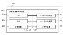
- FIG. 2 is a hardware configuration example of the radiography control device 100 of the radiography imaging system of the present embodiment.
- the radiography control device 100 includes a network device 201 connected to the network 140, a user input device 202 that accepts user operations such as a keyboard, and the like.
- the radiological imaging control device 100 includes an operation screen such as a liquid crystal display, a UI display device 203 for displaying a radiographic image, and a CPU 204 for controlling the entire radiographic imaging control device.
- an operation screen such as a liquid crystal display
- a UI display device 203 for displaying a radiographic image
- a CPU 204 for controlling the entire radiographic imaging control device.
- the radiography control device 100 is a storage device 206 that stores a RAM 205 that provides a workspace for the CPU 204, various control programs, a radiographic image received from the radiography camera 110, and image information received from the image acquisition device 130. Has.
- each device constituting the radiography control device 100 is connected by the main bus 207, and data can be transmitted and received to each other.
- the user input device 202 and the UI display device 203 are described as separate devices, an operation unit in which these devices are integrated may be used.
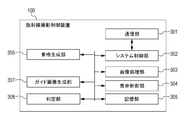
- FIG. 3 is an example of the functional configuration of the radiography control device 100 of the radiography imaging system of the present embodiment.
- Each functional unit shown in FIG. 3 is realized by the CPU 204 on the radiography control device 100 reading the control program stored in the storage device 206 onto the RAM 205 and executing the control program.
- the radiography control device 100 includes a communication unit 301, a system control unit 302, an image processing unit 303, a display control unit 304, a storage unit 305, a skeleton generation unit 306, a guide image generation unit 307, and a determination unit 308.
- the communication unit 301 is software that controls the network device 201 to perform communication.
- the system control unit 302 controls the image acquisition device 130, acquires irradiation information of the radiation generator 120 and imaging information of the radiation imaging device 110, and manages the respective states via the communication unit 301. Further, the system control unit 302 acquires a radiographic image from the radiographic imaging device 110 and an optical image from the image acquisition device 130 via the communication unit 301.
- system control unit 302 is a program that realizes the basic functions of the radiography control device 100, and controls the operation of each unit.
- the image processing unit 303 processes the radiographic image acquired via the system control unit 302 to generate an image to be used by the radiography control device 100.
- the display control unit 304 displays the image generated by the image processing unit 303 via the UI display device 203. Further, the display control unit 304 displays the guide image generated by the guide image generation unit 307 via the UI display device 203. Further, the display control unit 304 displays the past guide image generated from the images taken in the same posture in the past via the UI display device 203. Further, the display control unit 304 reflects the processing on the image instructed by the system control unit 302 based on the operation from the user input device 202, performs the processing of switching the screen display of the UI display device 203, and the like.
- the storage unit 305 uses the radiation image generated by the image processing unit 303, the patient's imaging conditions (patient ID, examination ID, examination site, imaging direction, etc.) related to the radiation image, and the irradiation information (tube) of the radiation generator 120. Save voltage, tube current, etc.). In addition, the storage unit 305 also stores the guide image generated by the guide image generation unit 307 related to the radiographic image.
- the skeleton generation unit 306 estimates the patient's skeleton and joint angle in the optical image using the optical image obtained from the image acquisition device 130, and generates information indicating the skeleton and information indicating the joint angle. Specifically, the skeleton generation unit 306 currently uses a trained model obtained by performing machine learning using the captured optical image of the human body as input data and the captured skeleton and joint angle of the human body as labels. Estimate the patient's skeleton and joint angles in the image. Then, information indicating the skeleton and information indicating the joint angle are generated from the estimated skeleton and joint angle.
- the trained model is a machine learning model that follows a machine learning algorithm such as deep learning using a support vector machine or a neural network, and is trained using appropriate learning data in advance.
- the machine learning model is shown. It should be noted that the trained model does not require further learning, and additional learning can be performed.
- the training data is composed of one or more pairs of input data and output data (correct answer data).
- the trained model according to the present embodiment is a model constructed by supervised learning using a neural network, and has input data (optical image of a human body) and a label (skeleton of the human body, joint angle). The set is learned as learning data.
- the skeleton generation unit 306 uses a trained model learned as a set of a plurality of optical images of the human body, information indicating the skeleton of the plurality of optical images in the human body, and information indicating the joint angle. It corresponds to an example of an estimation means for estimating the skeleton and joint angle of a subject from the optical image of 1.
- the machine learning algorithm and learning data set used for learning are not limited to the above, and for example, the model for estimating the skeleton and the model for estimating the joint angle may be different.
- the skeleton generation unit 306 generates information indicating the skeleton and information indicating the joint angle, but it may be configured to generate at least one of them.
- the skeleton generation unit 306 generates information indicating the joint angle, but the joint position may be learned as a label as well as the joint angle with respect to the trained model. In that case, the joint position is indicated. Information can be generated in the same way.
- the configuration is not limited as long as the skeleton generation unit 306 can generate information indicating the patient's skeleton and information indicating the joint angle in the optical image using the optical image obtained from the image acquisition device 130.
- the skeleton of the patient in the optical image is shown by acquiring the position information having the optical image and the distance information from the image acquisition device 130, acquiring the coordinates of each joint of the patient, and applying it to the human body data saved in advance. Information and information indicating the joint angle may be generated.
- the guide image generation unit 307 uses the information indicating the skeleton generated by the skeleton generation unit 306, the information indicating the joint angle, and the optical image obtained from the image acquisition device 130, and the information indicating the skeleton and the joint on the optical image. Generates a guide image in which information indicating the angle is superimposed and displayed. That is, based on the first optical image of the subject acquired at the first time point, at least one of the information indicating the skeleton of the subject and the information indicating the joint angle related to the first optical image. A first processed image containing information is generated. After that, the guide image generation unit 307 instructs the display control unit 304 to display the guide image on the screen.
- the guide image generation unit 307 acquires the information of the past guide image of the patient stored in the storage unit 305, and the past guide image. To generate. That is, based on the second optical image of the subject acquired at a second time point different from the first time point, the information indicating the skeleton of the subject related to the second optical image and the said. A second processed image containing at least one of the information indicating the joint angle is generated.
- the information of the past guide image includes, for example, the past image, the information indicating the skeleton of the patient related to the past image, and the information indicating the joint angle.
- the past guide image shows, for example, an image in which information indicating a skeleton related to the past image and information indicating a joint angle are superimposed on the past image.
- the guide image generation unit 307 instructs the display control unit 304 to display the guide image on which the past guide image is superimposed on the screen.
- the determination unit 308 determines whether or not there is information that matches the past patient imaging conditions of the storage unit 305 based on the imaging conditions of the patient to be imaged that are input in advance to the radiography control device 100 by the user.
- the determination unit 308 uses at least information on the patient ID, examination ID, examination site, and imaging direction as the imaging conditions of the patient, but the information can be determined to match the imaging conditions of the past patient. If so, there are no restrictions on the configuration.
- the determination unit 308 uses the latest information as the matched information.
- the information used as the matched information is not limited to the above, and does not have to be the latest information.
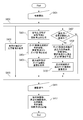
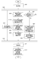
- FIG. 4 is a flowchart showing an example of a display processing process at the time of patient imaging of the radiography control device 100.
- step S401 the system control unit 302 sets the radiography control device 100 to the inspection start state for performing imaging control based on the user operation. Specifically, the system control unit 302 transmits an instruction to prepare for imaging to the radiography imaging device 110 via the communication unit 301 based on the imaging conditions of the patient instructed by the user operation. When the radiography imaging device 110 is ready for imaging, the radiography imaging device 110 returns and sends a notification of completion of preparation for radiography to the radiography imaging control device 100. After receiving the preparation completion notification, the system control unit 302 sets the radiography imaging control device 100 in an imaging enable state and accepts step S411 described later. Further, the system control unit 302 transmits an instruction to start shooting to the image acquisition device 130 via the communication unit 301. After receiving the imaging start instruction, the image acquisition device 130 returns to the radiography imaging control device 100 and sequentially transmits the optical images acquired by itself.
- step S402 and S410 sequential parallel processing by the system control unit 302 is executed. That is, it is a reception of control processing and user control in steps S403, steps S404 to S406, steps S407 to S409, and other operations.
- the processing between steps is executed by the system control unit 302 until step S411 is executed or the inspection is stopped (not shown) by the user operation.
- the processing between S402 and S410 does not necessarily have to be parallel processing, and is generated from an optical image of a patient, a guide image generated from the optical image, and an optical image of the patient taken in the past. It suffices if the past guide image can be displayed on the display device.
- step S403 After executing the process of step S403, the process of steps S404 to S406 may be executed, and then the processes of steps S407 to S409 may be performed.
- step S403 the system control unit 302 displays the optical image acquired from the image acquisition device 130 via the communication unit 301 on the UI display device 203 via the display control unit 304.
- step S404 the skeleton generation unit 306 generates information indicating the patient's skeleton and information indicating the joint angle in the optical image based on the optical image acquired via the system control unit 302.
- step S405 the guide image generation unit 307 generates a guide image based on the information indicating the skeleton generated by the skeleton generation unit 306 and the information indicating the joint angle.
- step S406 the display control unit 304 displays the first superimposed image 502 on which the guide image as shown in FIG. 5 is superimposed on the optical image on the UI display device 203. That is, the display control unit 304 displays at least one of the information indicating the skeleton of the subject and the information indicating the joint angle related to the first optical image obtained by optically photographing the subject as the first optical image.
- the first processed image generated by superimposing on the display unit is displayed on the display unit.
- Steps S403 to S406 are steps of superimposing the information indicating the skeleton and the information indicating the joint angle on the optical image obtained by photographing the patient undergoing the examination in real time and displaying the information on the UI display device 203. ..
- the optical image 500 is an optical image acquired from the image acquisition device 130 displayed on the UI display device 203 in step S403.
- an object within the imaging range of the image acquisition device 130 is reflected, such as the presence of the radiographing device 110 behind the patient, but for the sake of explanation, the patient's body is reflected in the optical image 500.
- the guide image 501 is an image generated by the guide image generation unit 307 based on the information indicating the patient's skeleton and the information indicating the joint angle generated by the skeleton generation unit 306.
- the guide image generation unit 307 gives an instruction to superimpose and display the guide image 501 on the optical image 500 to the display control unit 304, and the optical image 500 on which the guide image 501 is superimposed and displayed is displayed as the first superposed image 502.
- the joint angle of the patient generated by the skeleton generation unit 306 is displayed at the angle position formed between the joint positions of the human body.
- the display method there is no limitation on the display method as long as it is a method of expressing the joint angle in which the location of the joint position of the human body is specified.
- steps S407 to S409 information indicating the patient's skeleton and information indicating the joint angle are superimposed on the optical image obtained by photographing the patient under the same imaging conditions in the past, and the information is displayed on the UI display device 203. It is a process.
- step S407 the determination unit 308 determines whether or not there is a past imaging condition that matches the imaging condition of the patient instructed to be examined by searching the storage unit 305.
- step S408 the guide image generation unit 307 determines the optical image and the skeleton associated with the optical image from the imaging conditions of the storage unit 305.
- the information indicating the above and the information indicating the joint angle are acquired, and the second superimposed image 701 is generated.
- step S409 the display control unit 304 superimposes the second superimposed image 701 on the optical image and the guide image as shown in FIG. 7, and displays them on the UI display device 203. That is, the display control unit 304 uses at least one of the information indicating the skeleton of the subject and the information indicating the joint angle stored in association with the second optical image taken in the past of the first optical image. The second processed image generated by superimposing on the optical image of 2 is displayed on the display unit.
- the radiography control device 100 does not generate the past guide image, that is, does not execute the processes from step S408 to step S409. ..
- FIG. 6 is a diagram showing an example of the configuration of patient information stored in the storage unit 305.
- the storage unit 305 has a past patient imaging condition table 600, and is composed of an imaging condition unit 601 and a guide image information unit 602.
- the imaging condition unit 601 stores the radiation image generated by the image processing unit 303, the imaging conditions of the patient related to the radiation image, the irradiation information of the radiation generator 120, and the like.
- the determination unit 308 uses at least information such as the patient ID, the examination ID, the examination site, and the imaging direction as the imaging conditions of the patient, but can be used for determining the matching of the imaging conditions of the past patients. As long as it is information, there are no restrictions on the configuration. Further, in the present embodiment, when the imaging conditions of a plurality of past patients match, the determination unit 308 uses the latest information as the matched information.
- the information used as the matched information is not limited to the above, and does not have to be the latest information.
- the guide image information unit 602 includes an optical image acquired from the image acquisition device 130 and information indicating the skeleton generated by the skeleton generation unit 306 and a joint angle stored in the imaging condition unit 601 when the radiation image is generated by the image processing unit 303. Memorize the information indicating.
- the optical image, the information indicating the skeleton associated with the optical image, and the information indicating the joint angle are stored in association with each other, but the guide image generated by the guide image generation unit 307 is also combined. It may be stored, or it may be configured to store only the guide image.
- the information indicating the skeleton and the information indicating the joint angle are stored as image information, but only the joint coordinate information of the information indicating the skeleton is stored, and the guide image generation unit 307 stores the information indicating the skeleton from the joint coordinate information.
- the configuration may be such that information indicating the skeleton and information indicating the joint angle are generated. That is, the information indicating the skeleton and the information indicating the joint angle do not necessarily have to be stored / displayed as image information as shown in FIG. 6, but may be simply stored / displayed as characters or numerical parameters.
- the guide image generation unit 307 refers to the imaging condition table 600 of the past patient in the storage unit 305, but there is no limitation on the configuration as long as the determination in step S407 can be performed. That is, the determination may be made using the information on the information processing device (not shown) having the imaging condition table 600 of the past patient via the network 140.
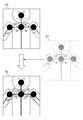
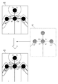
- FIG. 7 is a diagram showing an example of the configuration related to the display of the past guide image.
- the first superimposed image 700 is an image generated in the same manner as the above-mentioned first superimposed image 502.
- the guide image generation unit 307 displays an optical image that matches a predetermined imaging condition from the storage unit 305, information indicating the skeleton associated with the optical image, and information indicating the joint angle. Is an image generated based on them. Further, the guide image generation unit 307 gives an instruction to the display control unit 304 to superimpose and display the second superimposed image 701 on the first superimposed image 700. Then, the display control unit 304 that receives the display instruction displays the first superimposed image 700 in which the second superimposed image 701 is superimposed and displayed as the third superimposed image 702.
- step S411 the user presses the exposure switch 121 of the radiation generator 120 to start photographing.
- the radiation generator 120 When imaging is started, the radiation generator 120 generates radiation from the tube 122, the radiation that has passed through the patient is detected by the radiation imaging device 110, and the radiation imaging device generates a radiographic image. After that, the radiography imaging device 110 transmits a radiographic image to the radiography imaging control device 100. Further, in parallel with the processing, the radiation generator 120 transmits the irradiation information of the radiography to the radiography control device 100.
- step S412 the system control unit 302 stores the radiation image, the imaging conditions of the patient related to the radiation image, the irradiation information of the radiation generator 120, and the like in the storage unit 305. Further, in parallel with the above processing, the system control unit 302 stores the optical image at the time of photographing, the information indicating the skeleton associated with the optical image, and the information indicating the joint angle in the storage unit 305.
- the processing of the radiography system according to the present embodiment is performed.
- the display control unit 304 is a guide image generated based on the optical image acquired from the image acquisition device 130 at the start of the inspection, the information indicating the skeleton generated by the skeleton generation unit 306, and the information indicating the joint angle. Are superimposed and displayed on the UI display device 203. Further, the display control unit 304 determines a patient who has taken an image under the same imaging conditions in the past, and is based on an optical image of the past examination, information indicating a skeleton associated with the optical image, and information indicating a joint angle. The past guide image generated in this manner is superimposed and displayed on the UI display device 203.
- the inspector quantitatively positions the information based on the information indicating the skeleton superimposed on the past image and the information indicating the joint angle, and the information indicating the skeleton superimposed on the current image and the information indicating the joint angle. It can be performed.
- the display control unit 304 superimposes the information indicating the skeleton related to the current image and the information indicating the joint angle, and the information indicating the skeleton and the joint angle stored in association with the past image.
- the positioning accuracy was improved by superimposing and displaying the past image on which the information indicating the above is superimposed.
- the display control unit 304 changes the pixel value based on the information indicating the skeleton related to the current image and the information indicating the joint angle, and the skeleton stored in association with the past image.
- the past image whose pixel value is changed based on the information indicating the above and the information indicating the angle of the joint is superimposed and displayed.
- a guide image is generated by changing the pixel value of.
- the past guide image is generated by changing the pixel values of the pixels constituting the past image so that the information indicating the patient's skeleton and the information indicating the joint angle in the past image can be visually recognized.
- the examiner obtains the information indicating the skeleton superimposed and displayed on the past image and the information indicating the joint angle, and the information indicating the skeleton superimposed and displayed on the current image and the joint angle. Positioning can be performed quantitatively based on the information shown.
- the display control unit 304 superimposes the information indicating the skeleton related to the current image and the information indicating the joint angle, and the information indicating the skeleton and the joint angle stored in association with the past image.
- the positioning accuracy was improved by superimposing and displaying the past image on which the information indicating the above is superimposed.
- the display control unit 304 has only information indicating the skeleton related to the current image and information indicating the joint angle and information indicating the skeleton stored in association with the past image and information indicating the joint angle. Are superimposed and displayed.
- the guide image 501 as shown in FIG. 5 and the past guide image 901 as shown in FIG. 9 are superimposed and displayed.
- positioning can be performed based only on the information indicating the skeleton and the information indicating the angle of the joint without displaying the optical image of the patient, so that the patient's privacy is taken into consideration and the quantity is quantified. Positioning can be performed.
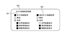
- FIG. 8 is a diagram showing an example of the configuration of the guide image setting screen of the radiography control device 100 of the present embodiment.
- the guide image generation unit 307 additionally has a guide image setting screen 800, and the guide image setting screen 800 is a display instruction from the system control unit 302 (for example, the user operates the radiography control device 100 and the system setting screen. It is displayed on the UI display device 203 by (for example, when the screen is selected from (not shown)).
- the guide image setting screen 800 has a guide image setting unit 801 and a past guide image setting unit 802.
- the guide image setting unit 801 has a setting related to the optical image and the guide image generated based on the information indicating the skeleton and the information indicating the joint angle related to the optical image.
- the radiography control device 100 does not generate the guide image. Specifically, the processes of steps S403 to S406 of FIG. 4 described above are not executed.
- the display of the optical image, the information indicating the skeleton associated with the optical image, and the information indicating the joint angle is additionally set. Of the items, only the items that are validly set by the user are displayed as the optical image and the guide image of the radiography control device 100. In the description of the present embodiment, the description will be continued with the display of the optical image, the information indicating the skeleton associated with the optical image, and the information indicating the joint angle enabled.
- the past guide image setting unit 802 is generated based on the optical images taken in the past that match the predetermined shooting conditions, the information indicating the skeleton associated with the optical images, and the information indicating the joint angle. Has settings related to past guide images.
- the radiography control device 100 does not generate the past guide image. Specifically, the process of steps S407 to S409 of FIG. 4 described above is not executed.
- the display of the optical image, the information indicating the skeleton associated with the optical image, and the information indicating the joint angle is additionally set. Only the items that are validly set by the user will be displayed as the past guide image of the radiography control device 100. In the description of the present embodiment, the description will be continued assuming that the display of the information indicating the skeleton and the information indicating the joint angle is enabled.
- the location and position of the joint angle may be additionally displayed. Specifically, for example, the joint angle and the joint position information may be displayed together, or the location of the joint angle portion may be highlighted by enclosing it with a figure.
- FIG. 9 is a diagram showing an example of the configuration related to the display of the past guide image. Since the configuration for displaying the optical image and the guide image is the same as that in the first embodiment, the description of the same configuration will be omitted. Further, the guide image setting of the radiography control device 100 here is based on the setting of the guide image setting screen 800 of FIG.
- the superimposed image 900 is an image generated by the guide image generation unit 307 in steps S403 to S406 of the first embodiment based on the settings of the guide image setting screen 800.
- the guide image generation unit 307 acquires and generates information indicating the skeleton and joint angle from the storage unit 305 based on the setting of the guide image setting screen 800 in step S408 of the first embodiment. It is an image.
- the guide image generation unit 307 gives an instruction to superimpose and display the past guide image 901 on the superposed image 900 to the display control unit 304, and the superposed image 900 on which the past guide image 901 is superposed and displayed is displayed as the past guide superposed image 902. .
- the radiography control device 100 controls the display of the guide image based on the user setting, the guide image based on the display content setting of the past guide image, and the past guide image. As a result, the user can selectively display appropriate information for reproducing the positioning.
- the radiography control device 100 adds a process of generating a guide image based on the three-dimensional patient skeleton information and the joint angle.
- FIG. 10 is a configuration example of the radiography control device 100 of the radiography system of the present embodiment.
- the radiography control device 100 additionally has a three-dimensional skeleton generation unit 1000.
- the three-dimensional skeleton generation unit 1000 generates information indicating a three-dimensional skeleton and information indicating a three-dimensional joint angle.
- the generation method the same method as in the first embodiment can be used.
- the three-dimensional skeleton generator 1000 uses a trained model obtained by performing machine learning using an optical image of a human body as input data and a three-dimensional skeleton and joint angle of the captured human body as labels. , Estimate the skeleton and joint positions of the human body in the current image.
- the three-dimensional image used as the input data may be generated, for example, by synthesizing two-dimensional images captured from different angles by a plurality of optical cameras.
- the three-dimensional image used as the input data may be generated from the two-dimensional image taken by driving one optical camera and changing the angle. That is, in the present embodiment, the method of acquiring the three-dimensional image is not limited, and it is sufficient that the three-dimensional image obtained by capturing the subject is acquired.
- information indicating a three-dimensional skeleton and information indicating a three-dimensional joint angle are generated.
- the information generated in the present embodiment may be generated based on a two-dimensional optical image or may be generated based on a three-dimensional optical image.
- the configuration of the three-dimensional skeleton generation unit 1000 is not limited as long as it can generate information indicating the three-dimensional skeleton and information indicating the three-dimensional joint angle. For example, by acquiring position information having optical image and distance information from the image acquisition device 130, acquiring the coordinates of each joint of the patient, and applying it to the human body data saved in advance, the three-dimensional shape of the patient in the optical image can be obtained. Information indicating the skeleton and information indicating the three-dimensional joint angle may be generated.
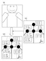
- FIG. 11 is a flowchart showing an example of a display processing process at the time of patient imaging of the radiography control device 100 of the present embodiment.
- step S1101 the three-dimensional skeleton generation unit 1000 uses the information indicating the skeleton generated by the skeleton generation unit 306 and the information indicating the joint angle to provide information indicating the three-dimensional skeleton and information indicating the three-dimensional joint angle. Generate. Therefore, in the subsequent step S406, a guide image is generated based on the information indicating the three-dimensional skeleton generated by the three-dimensional skeleton generation unit 1000 and the information indicating the three-dimensional joint angle, and the UI is generated via the display control unit 304.
- the display device 203 superimposes and displays the optical image.
- step S408 for the generation of the past guide image, the information indicating the three-dimensional skeleton generated by the three-dimensional skeleton generation unit 1000 stored in correspondence with the past image and the information indicating the three-dimensional joint angle are used.
- the three-dimensional guide image 1201 is an image generated by the guide image generation unit 307 based on the information indicating the three-dimensional skeleton of the patient and the information indicating the three-dimensional joint angle generated by the three-dimensional skeleton generation unit 1000 in step S1101. Is.
- the guide image generation unit 307 gives an instruction to the display control unit 304 to superimpose and display the three-dimensional guide image 1201 on the optical image 500, and the optical image 500 on which the three-dimensional guide image 1201 is superposed and displayed as the guide image superimposition display image 1202 is displayed. Is displayed.
- the information indicating the three-dimensional joint angle of the patient generated by the three-dimensional skeleton generation unit 1000 is expressed by the character string display in the three-dimensional polar coordinate format. That is, for the information indicating the skeleton in the direction from the inside to the outside at the joint position of the human body, the angle ⁇ formed by the z-axis and the angle ⁇ formed by the information indicating the skeleton lowered on the x-axis and the xy plane are displayed. ..
- the method is not limited to the above as long as it is a method for expressing a three-dimensional joint angle.
- the radiography control device 100 generates a guide image based on the information indicating the three-dimensional skeleton and the information indicating the three-dimensional joint angle.
- the user can refer to the information indicating the three-dimensional skeleton and the information indicating the three-dimensional joint angle, and the reproducibility of the positioning of the user's posture can be further improved.
- the radiography control device 100 has a configuration in which the patient himself / herself can improve the reproducibility of the posture by showing the image displayed on the UI display device 203 to the patient.
- the display control unit 304 additionally has a control function capable of displaying the optical image, the superimposed display image, or the past superimposed display image displayed on the UI display device 203 in reverse left and right (not shown).
- the user activates the control function and presents the UI display device 203 to the patient.
- the patient himself can confirm the superimposed display of the past guide image generated based on the information indicating the joint angle.
- the patient himself in addition to improving the reproducibility of the posture positioning of the user, the patient himself can improve the reproducibility of the posture.
Landscapes
- Engineering & Computer Science (AREA)
- Life Sciences & Earth Sciences (AREA)
- Health & Medical Sciences (AREA)
- Medical Informatics (AREA)
- Physics & Mathematics (AREA)
- Heart & Thoracic Surgery (AREA)
- General Health & Medical Sciences (AREA)
- High Energy & Nuclear Physics (AREA)
- Veterinary Medicine (AREA)
- Nuclear Medicine, Radiotherapy & Molecular Imaging (AREA)
- Optics & Photonics (AREA)
- Pathology (AREA)
- Radiology & Medical Imaging (AREA)
- Biomedical Technology (AREA)
- Public Health (AREA)
- Molecular Biology (AREA)
- Surgery (AREA)
- Animal Behavior & Ethology (AREA)
- Biophysics (AREA)
- General Physics & Mathematics (AREA)
- Theoretical Computer Science (AREA)
- Human Computer Interaction (AREA)
- Computer Graphics (AREA)
- Computer Hardware Design (AREA)
- General Engineering & Computer Science (AREA)
- Software Systems (AREA)
- Computer Vision & Pattern Recognition (AREA)
- Apparatus For Radiation Diagnosis (AREA)
- Image Processing (AREA)
- Image Analysis (AREA)
Priority Applications (1)
| Application Number | Priority Date | Filing Date | Title |
|---|---|---|---|
| US17/742,238 US20220265228A1 (en) | 2019-11-18 | 2022-05-11 | Radiation imaging system, radiation imaging method, image processing apparatus, and storage medium |
Applications Claiming Priority (2)
| Application Number | Priority Date | Filing Date | Title |
|---|---|---|---|
| JP2019208330A JP7527773B2 (ja) | 2019-11-18 | 2019-11-18 | 放射線撮影システム、放射線撮影方法、画像処理装置およびプログラム |
| JP2019-208330 | 2019-11-18 |
Related Child Applications (1)
| Application Number | Title | Priority Date | Filing Date |
|---|---|---|---|
| US17/742,238 Continuation US20220265228A1 (en) | 2019-11-18 | 2022-05-11 | Radiation imaging system, radiation imaging method, image processing apparatus, and storage medium |
Publications (1)
| Publication Number | Publication Date |
|---|---|
| WO2021100513A1 true WO2021100513A1 (ja) | 2021-05-27 |
Family
ID=75965711
Family Applications (1)
| Application Number | Title | Priority Date | Filing Date |
|---|---|---|---|
| PCT/JP2020/041695 Ceased WO2021100513A1 (ja) | 2019-11-18 | 2020-11-09 | 放射線撮影システム、放射線撮影方法、画像処理装置およびプログラム |
Country Status (3)
| Country | Link |
|---|---|
| US (1) | US20220265228A1 (enExample) |
| JP (1) | JP7527773B2 (enExample) |
| WO (1) | WO2021100513A1 (enExample) |
Cited By (1)
| Publication number | Priority date | Publication date | Assignee | Title |
|---|---|---|---|---|
| WO2024090050A1 (ja) * | 2022-10-27 | 2024-05-02 | 富士フイルム株式会社 | 画像処理装置、方法およびプログラム、並びに学習装置、方法およびプログラム |
Families Citing this family (6)
| Publication number | Priority date | Publication date | Assignee | Title |
|---|---|---|---|---|
| JP7375666B2 (ja) * | 2020-04-20 | 2023-11-08 | オムロン株式会社 | 推定装置、学習装置、教師データ作成装置、推定方法、学習方法、教師データ作成方法、及びプログラム |
| JP2023116868A (ja) * | 2022-02-10 | 2023-08-23 | コニカミノルタ株式会社 | 放射線撮影装置、撮影支援方法及びプログラム |
| EP4364668A1 (en) * | 2022-11-03 | 2024-05-08 | Koninklijke Philips N.V. | A device, computer program product and method for assisting in positioning at least one body part of a patent for an x-ray acquisition |
| JP2024115138A (ja) * | 2023-02-14 | 2024-08-26 | 富士フイルムヘルスケア株式会社 | 医用画像撮像装置及びその制御方法 |
| CN120676906A (zh) * | 2023-02-21 | 2025-09-19 | 富士胶片株式会社 | 信息处理装置、信息处理方法及信息处理程序 |
| JP7670088B2 (ja) * | 2023-07-07 | 2025-04-30 | コニカミノルタ株式会社 | 医用画像撮影システム、撮影制御装置、医用画像撮影方法及びプログラム |
Citations (6)
| Publication number | Priority date | Publication date | Assignee | Title |
|---|---|---|---|---|
| JP2004057804A (ja) * | 2002-06-05 | 2004-02-26 | Fuji Photo Film Co Ltd | 骨関節評価方法、装置およびそのためのプログラム |
| WO2013085048A1 (ja) * | 2011-12-08 | 2013-06-13 | シャープ株式会社 | 情報端末装置、遠隔測定システム、情報端末装置の制御方法、制御プログラムおよび記録媒体 |
| JP2014117368A (ja) * | 2012-12-14 | 2014-06-30 | Toshiba Corp | X線診断装置及びその制御方法 |
| JP2015198824A (ja) * | 2014-04-09 | 2015-11-12 | 株式会社東芝 | 医用画像診断装置 |
| WO2016086266A1 (en) * | 2014-12-05 | 2016-06-09 | Myfiziq Limited | Imaging a body |
| JP2017136300A (ja) * | 2016-02-05 | 2017-08-10 | 東芝メディカルシステムズ株式会社 | X線撮影システム |
Family Cites Families (10)
| Publication number | Priority date | Publication date | Assignee | Title |
|---|---|---|---|---|
| WO2007061099A1 (ja) * | 2005-11-25 | 2007-05-31 | Kabushiki Kaisha Toshiba | 医用画像診断装置、医用画像保管通信システム用サーバ、画像参照装置、及び医用画像診断システム |
| US8562403B2 (en) * | 2010-06-11 | 2013-10-22 | Harmonix Music Systems, Inc. | Prompting a player of a dance game |
| US10033979B2 (en) * | 2012-03-23 | 2018-07-24 | Avigilon Fortress Corporation | Video surveillance systems, devices and methods with improved 3D human pose and shape modeling |
| KR20140116740A (ko) * | 2013-03-25 | 2014-10-06 | 삼성전자주식회사 | 안무 영상을 표시하는 디스플레이 장치 및 표시 방법 |
| EP2808760B1 (en) * | 2013-05-29 | 2023-08-16 | Dassault Systèmes | Body posture tracking |
| US10670679B2 (en) * | 2016-07-01 | 2020-06-02 | Canon Medical Systems Corporation | Magnetic resonance imaging apparatus and image processing apparatus |
| US20180121729A1 (en) * | 2016-11-02 | 2018-05-03 | Umbo Cv Inc. | Segmentation-based display highlighting subject of interest |
| JP7067912B2 (ja) * | 2017-12-13 | 2022-05-16 | キヤノン株式会社 | 放射線撮像装置および放射線撮像システム |
| US20190370537A1 (en) * | 2018-05-29 | 2019-12-05 | Umbo Cv Inc. | Keypoint detection to highlight subjects of interest |
| US10956724B1 (en) * | 2019-09-10 | 2021-03-23 | Facebook Technologies, Llc | Utilizing a hybrid model to recognize fast and precise hand inputs in a virtual environment |
-
2019
- 2019-11-18 JP JP2019208330A patent/JP7527773B2/ja active Active
-
2020
- 2020-11-09 WO PCT/JP2020/041695 patent/WO2021100513A1/ja not_active Ceased
-
2022
- 2022-05-11 US US17/742,238 patent/US20220265228A1/en not_active Abandoned
Patent Citations (6)
| Publication number | Priority date | Publication date | Assignee | Title |
|---|---|---|---|---|
| JP2004057804A (ja) * | 2002-06-05 | 2004-02-26 | Fuji Photo Film Co Ltd | 骨関節評価方法、装置およびそのためのプログラム |
| WO2013085048A1 (ja) * | 2011-12-08 | 2013-06-13 | シャープ株式会社 | 情報端末装置、遠隔測定システム、情報端末装置の制御方法、制御プログラムおよび記録媒体 |
| JP2014117368A (ja) * | 2012-12-14 | 2014-06-30 | Toshiba Corp | X線診断装置及びその制御方法 |
| JP2015198824A (ja) * | 2014-04-09 | 2015-11-12 | 株式会社東芝 | 医用画像診断装置 |
| WO2016086266A1 (en) * | 2014-12-05 | 2016-06-09 | Myfiziq Limited | Imaging a body |
| JP2017136300A (ja) * | 2016-02-05 | 2017-08-10 | 東芝メディカルシステムズ株式会社 | X線撮影システム |
Cited By (1)
| Publication number | Priority date | Publication date | Assignee | Title |
|---|---|---|---|---|
| WO2024090050A1 (ja) * | 2022-10-27 | 2024-05-02 | 富士フイルム株式会社 | 画像処理装置、方法およびプログラム、並びに学習装置、方法およびプログラム |
Also Published As
| Publication number | Publication date |
|---|---|
| JP7527773B2 (ja) | 2024-08-05 |
| US20220265228A1 (en) | 2022-08-25 |
| JP2021078692A (ja) | 2021-05-27 |
Similar Documents
| Publication | Publication Date | Title |
|---|---|---|
| JP7527773B2 (ja) | 放射線撮影システム、放射線撮影方法、画像処理装置およびプログラム | |
| CN108324246B (zh) | 医疗诊断辅助系统及方法 | |
| RU2714665C2 (ru) | Направляющая система для позиционирования пациента для медицинской визуализации | |
| CA3055941C (en) | Augmented reality diagnosis guidance | |
| JP5377153B2 (ja) | 画像処理装置、画像処理プログラムおよび医用診断システム | |
| US10646190B2 (en) | Radiography guide system and method | |
| JP2008194374A (ja) | 放射線画像投影装置および方法 | |
| US10078906B2 (en) | Device and method for image registration, and non-transitory recording medium | |
| CN115670650A (zh) | 用于动态注释医学图像的方法和系统 | |
| JP2020102037A (ja) | 情報処理装置、放射線撮影システムおよび支援方法 | |
| JP2024161485A (ja) | 写損判断支援装置及びプログラム | |
| US10102638B2 (en) | Device and method for image registration, and a nontransitory recording medium | |
| US20110218425A1 (en) | Medical image generating apparatus, medical image display apparatus, medical image generating method and program | |
| JP2021097727A (ja) | 画像処理装置、画像処理方法およびプログラム | |
| JP7099086B2 (ja) | 動態画像処理装置及びプログラム | |
| JP2021069698A (ja) | 放射線撮影装置、放射線撮影システム、放射線撮影方法及びプログラム | |
| JP5738000B2 (ja) | 放射線撮影システム及びその制御方法、並びに、プログラム | |
| US10049480B2 (en) | Image alignment device, method, and program | |
| WO2021111939A1 (ja) | 放射線撮影システム、放射線撮影方法、医用画像撮影システムおよびプログラム | |
| JP2005110844A (ja) | X線画像撮影装置及び撮影方法 | |
| KR101834081B1 (ko) | 3d 영상 디스플레이 방법 및 3d 영상을 이용한 방사선 촬영 가이드 시스템 및 방법 | |
| JP2018175320A (ja) | 放射線撮影システム | |
| KR20150047935A (ko) | 다중 의료 영상을 표시하는 방법 및 이를 수행하기 위한 의료 영상 기기 | |
| US20250095194A1 (en) | Image processing apparatus, storage medium, and image processing method | |
| US20240090864A1 (en) | Radiographic imaging support system, radiographic imaging support method, and recording medium |
Legal Events
| Date | Code | Title | Description |
|---|---|---|---|
| 121 | Ep: the epo has been informed by wipo that ep was designated in this application |
Ref document number: 20888802 Country of ref document: EP Kind code of ref document: A1 |
|
| NENP | Non-entry into the national phase |
Ref country code: DE |
|
| 122 | Ep: pct application non-entry in european phase |
Ref document number: 20888802 Country of ref document: EP Kind code of ref document: A1 |