WO2021090540A1 - 複合線 - Google Patents
複合線 Download PDFInfo
- Publication number
- WO2021090540A1 WO2021090540A1 PCT/JP2020/028621 JP2020028621W WO2021090540A1 WO 2021090540 A1 WO2021090540 A1 WO 2021090540A1 JP 2020028621 W JP2020028621 W JP 2020028621W WO 2021090540 A1 WO2021090540 A1 WO 2021090540A1
- Authority
- WO
- WIPO (PCT)
- Prior art keywords
- line
- core wire
- cross
- section
- composite
- Prior art date
- Legal status (The legal status is an assumption and is not a legal conclusion. Google has not performed a legal analysis and makes no representation as to the accuracy of the status listed.)
- Ceased
Links
Images
Classifications
-
- D—TEXTILES; PAPER
- D02—YARNS; MECHANICAL FINISHING OF YARNS OR ROPES; WARPING OR BEAMING
- D02G—CRIMPING OR CURLING FIBRES, FILAMENTS, THREADS, OR YARNS; YARNS OR THREADS
- D02G3/00—Yarns or threads, e.g. fancy yarns; Processes or apparatus for the production thereof, not otherwise provided for
- D02G3/02—Yarns or threads characterised by the material or by the materials from which they are made
- D02G3/04—Blended or other yarns or threads containing components made from different materials
-
- D—TEXTILES; PAPER
- D02—YARNS; MECHANICAL FINISHING OF YARNS OR ROPES; WARPING OR BEAMING
- D02G—CRIMPING OR CURLING FIBRES, FILAMENTS, THREADS, OR YARNS; YARNS OR THREADS
- D02G3/00—Yarns or threads, e.g. fancy yarns; Processes or apparatus for the production thereof, not otherwise provided for
- D02G3/02—Yarns or threads characterised by the material or by the materials from which they are made
- D02G3/12—Threads containing metallic filaments or strips
-
- D—TEXTILES; PAPER
- D02—YARNS; MECHANICAL FINISHING OF YARNS OR ROPES; WARPING OR BEAMING
- D02G—CRIMPING OR CURLING FIBRES, FILAMENTS, THREADS, OR YARNS; YARNS OR THREADS
- D02G3/00—Yarns or threads, e.g. fancy yarns; Processes or apparatus for the production thereof, not otherwise provided for
- D02G3/22—Yarns or threads characterised by constructional features, e.g. blending, filament/fibre
- D02G3/36—Cored or coated yarns or threads
-
- D—TEXTILES; PAPER
- D02—YARNS; MECHANICAL FINISHING OF YARNS OR ROPES; WARPING OR BEAMING
- D02G—CRIMPING OR CURLING FIBRES, FILAMENTS, THREADS, OR YARNS; YARNS OR THREADS
- D02G3/00—Yarns or threads, e.g. fancy yarns; Processes or apparatus for the production thereof, not otherwise provided for
- D02G3/22—Yarns or threads characterised by constructional features, e.g. blending, filament/fibre
- D02G3/38—Threads in which fibres, filaments, or yarns are wound with other yarns or filaments, e.g. wrap yarns, i.e. strands of filaments or staple fibres are wrapped by a helically wound binder yarn
-
- D—TEXTILES; PAPER
- D07—ROPES; CABLES OTHER THAN ELECTRIC
- D07B—ROPES OR CABLES IN GENERAL
- D07B1/00—Constructional features of ropes or cables
- D07B1/02—Ropes built-up from fibrous or filamentary material, e.g. of vegetable origin, of animal origin, regenerated cellulose, plastics
- D07B1/04—Ropes built-up from fibrous or filamentary material, e.g. of vegetable origin, of animal origin, regenerated cellulose, plastics with a core of fibres or filaments arranged parallel to the centre line
-
- D—TEXTILES; PAPER
- D07—ROPES; CABLES OTHER THAN ELECTRIC
- D07B—ROPES OR CABLES IN GENERAL
- D07B1/00—Constructional features of ropes or cables
- D07B1/06—Ropes or cables built-up from metal wires, e.g. of section wires around a hemp core
-
- D—TEXTILES; PAPER
- D07—ROPES; CABLES OTHER THAN ELECTRIC
- D07B—ROPES OR CABLES IN GENERAL
- D07B1/00—Constructional features of ropes or cables
- D07B1/16—Ropes or cables with an enveloping sheathing or inlays of rubber or plastics
-
- A—HUMAN NECESSITIES
- A01—AGRICULTURE; FORESTRY; ANIMAL HUSBANDRY; HUNTING; TRAPPING; FISHING
- A01K—ANIMAL HUSBANDRY; AVICULTURE; APICULTURE; PISCICULTURE; FISHING; REARING OR BREEDING ANIMALS, NOT OTHERWISE PROVIDED FOR; NEW BREEDS OF ANIMALS
- A01K91/00—Lines
Definitions
- the technique disclosed herein relates to a composite wire comprising a plurality of wires formed of materials having different shear strengths.
- Fishing line with metal wire and resin wire is widely used.
- a fishing line by providing a metal wire and a resin wire, both the strength and the flexibility of the fishing line are achieved.
- a fishing line including a resin wire and a metal wire spirally wound around the resin wire is known (for example, Patent Document 1).
- the conventional fishing line has a structure in which a metal wire is spirally wound around a resin wire, for example, the fishing line collides with an obstacle (for example, a rock, an underwater fish, or another fishing line), and the fishing line is used.
- an obstacle for example, a rock, an underwater fish, or another fishing line
- such a problem is not limited to a fishing line having a metal wire and a resin wire, but is a common problem if it is a composite wire having a plurality of wires formed of materials having different shear strengths.
- This specification discloses a technique capable of solving the above-mentioned problems.
- the techniques disclosed herein can be realized, for example, in the following forms.
- the composite wire disclosed in the present specification is a core wire having a cross-sectional contour line having a shape other than a perfect circle, and a spiral first surface centered on the longitudinal direction of the core wire is formed.
- a spiral first side wire formed of a material having a shear strength lower than the shear strength of the material forming the core wire and arranged on the first surface. , Equipped with.
- the first lateral line having a low shear strength is arranged on the spiral first surface of the core wire, so that when a force is applied to the composite wire, The shearing force applied to the first lateral line through the core wire is suppressed. Therefore, according to this composite wire, as compared with the conventional fishing line in which a metal wire is spirally wound around a resin wire, when a force is applied to the composite wire, the wire is passed through the core wire. It is possible to prevent the first lateral line from breaking due to the application of a shearing force to the first lateral line.
- the core wire and the first side wire may be in surface contact with each other.
- the contact area between the core wire and the first lateral line is larger than that in the configuration in which the core wire and the first lateral line are in point contact with each other. Therefore, when a force is applied to the composite wire, the force applied to the first lateral line is dispersed through the core wire, so that the force applied to the first lateral line per unit area becomes smaller. As a result, when a force is applied to the composite wire, damage to the first lateral line due to the force being applied to the first lateral line via the core wire is suppressed.
- the contour line of the cross section of the core wire has a first straight line portion which is a part of the first surface, and the first lateral line is the first straight line. It may be configured to be in contact with the portion. According to this composite wire, it is possible to easily realize a configuration in which the core wire and the first side wire are in surface contact with each other.
- the contour line of the cross section of the core wire may be a polygon having the first straight line portion in contact with the first lateral line as a side. According to this composite wire, it is possible to easily realize a configuration in which the first lateral line is in contact with the first straight line portion of the core wire. Further, in the present composite wire, since the contour line of the cross section of the core wire is polygonal, the core wire can be easily manufactured by wire drawing processing or swaging processing using a deformed die.
- the contour line of the cross section of the core wire may be a quadrangle having the first straight line portion in contact with the first lateral line as a side.
- the core wire of this composite wire can be more easily manufactured by wire drawing or swaging using a deformed die.
- the contour line of the cross section of the core wire may be a rectangle having the first straight line portion in contact with the first side line as a long side. According to this composite line, while ensuring a sufficient length of the first straight line portion, the diameter of the composite line (more specifically, orthogonal to the first straight line portion in the cross section of the composite line). The diameter in the direction of rotation) can be reduced.
- the width of the core wire in the first direction which is a direction parallel to the cross section, is shorter than the width in the direction orthogonal to the first direction, and the first The surface of 1 is located on one side of the core wire in the first direction, and the first side line is separated from both ends of the core wire in a direction orthogonal to the first direction on the first surface of the core wire. It may be configured as such.
- the width in the direction orthogonal to the first direction is basically increased.
- the relatively long core wire directly receives the force, which prevents the first side wire from breaking.
- the core wire may be made of metal and the first side wire may be made of resin. According to this composite wire, it is possible to easily realize a configuration including the core wire having the above-mentioned configuration and high strength and the first side wire having the above-mentioned configuration but high flexibility.
- the core wire is a second surface opposite to the first surface in a direction substantially orthogonal to the longitudinal direction, and is a spiral first surface centered on the longitudinal direction.
- the composite wire having two surfaces is further formed of a material having a shear strength lower than the shear strength of the material forming the core wire, and a spiral second surface arranged on the second surface. It may be configured to include a side line of.
- the second lateral line having a low shear strength is arranged on the spiral second surface of the core wire, so that when a force is applied to the composite wire, the second lateral wire is passed through the core wire. The shearing force applied to the second lateral line is suppressed.
- this composite wire as compared with the conventional fishing line in which a metal wire is spirally wound around a resin wire, when a force is applied to the composite wire, the wire is passed through the core wire. It is possible to prevent the second lateral line from breaking due to the application of a shearing force to the second lateral line.
- the core wire and the second side wire may be in surface contact with each other.
- the contact area between the core wire and the second lateral line is larger than that in the configuration in which the core wire and the second lateral line are in point contact with each other. Therefore, the odor of the composite wire is per unit area applied to the second lateral line by dispersing the force applied to the second lateral line through the core wire when a force is applied to the composite wire. The force is reduced, and when a force is applied to the composite wire, damage to the second lateral line due to the force being applied to the second lateral line via the core wire is suppressed. ..
- the contour line of the cross section of the core wire has a second straight line portion which is a part of the second surface, and the second side line is the second straight line. It may be configured to be in contact with the portion. According to this composite wire, it is possible to easily realize a configuration in which the core wire and the second side wire are in surface contact with each other.
- the contour line of the cross section of the core wire may be a polygon having the second straight line portion in contact with the second side line as a side. According to this composite wire, it is possible to easily realize a configuration in which the second lateral line is in contact with the second straight line portion of the core wire.
- the contour line of the cross section of the core wire may be a rectangle having the first straight line portion in contact with the first side line as a long side.
- the core wire can be more easily manufactured by wire drawing or swaging using a deformed die.
- the contour line of the cross section of the core wire may be a rectangle having the second straight line portion in contact with the second side line as a long side. Therefore, according to the present composite line, while sufficiently securing the length of the second straight line portion, the diameter of the composite line (more specifically, the second straight line portion in the cross section of the composite line). The diameter in the direction orthogonal to) can be reduced.
- the width of the core wire in the first direction which is a direction parallel to the cross section, is shorter than the width in the direction orthogonal to the first direction, and the first The surface of 1 is located on one side of the core wire in the first direction, the second surface is located on the other side of the core wire in the first direction, and the first side line is The core wire is separated from both ends in a direction orthogonal to the first direction on the first surface of the core wire, and the second side line is orthogonal to the first direction on the second surface of the core wire. It may be configured to be separated from both ends in the direction of movement.
- the width in the direction orthogonal to the first direction is basically increased.
- the relatively long core wire directly receives the force, which prevents the first side wire and the second side wire from breaking.
- the second lateral line may be formed of a resin. According to this composite line, it is possible to easily realize a configuration including the second lateral line having high flexibility despite the above-described configuration.
- the technique disclosed in the present specification can be realized in various forms, for example, a composite line, a method for manufacturing a composite line, and the like.
- the figure which shows the appearance structure of the fishing line 10 in this embodiment Perspective view showing the appearance configuration of the core wire 20
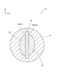
- FIG. 1 is a cross-sectional view schematically showing the cross-sectional structure of the fishing line 10 in the present embodiment, and shows the XZ cross-sectional structure of the fishing line 10 at the position II of FIG.
- the "cross section” is a cross section (XZ cross section) substantially orthogonal to the longitudinal direction of the fishing line 10 (the same applies hereinafter to the "cross section”).
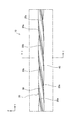
- FIG. 2 is a diagram showing an external configuration of the fishing line 10 in the present embodiment, and shows a YZ plane configuration of the fishing line 10 shown in FIG. In FIG. 2, the coating layer 50, which will be described later, is not shown.
- Each figure shows XYZ axes that are orthogonal to each other to identify the direction.
- the fishing line 10 includes a core wire 20, a first lateral line 30, a second lateral line 40, and a covering layer 50.
- the outer diameter of the fishing line 10 is set to, for example, 0.01 mm or more and 3 mm or less (preferably 0.01 mm or more and 1 mm or less).
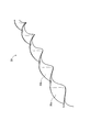
- FIG. 3 is a perspective view showing the external configuration of the core wire 20.
- the core wire 20 is made of metal.
- the metal forming the core wire 20 is not particularly limited, but is not limited to stainless steel (SUS304, SUS316, etc.), cobalt-chromium alloy, nickel-cobalt alloy, brass, titanium, titanium alloy, tungsten, renium tungsten, renium tungsten alloy. And so on.
- the core wire 20 has a configuration in which the core wire 20 is twisted about the longitudinal direction (Y-axis direction) of the core wire 20. That is, the core wire 20 is a member formed by twisting, for example, a substantially plate-shaped metal wire about the longitudinal direction of the metal wire.
- the core wire 20 has a configuration in which the core wire 20 is twisted around the longitudinal direction of the core wire 20, for example, while winding a substantially plate-shaped metal wire formed of the above metal around the bobbin, the bobbin is wound in the longitudinal direction of the metal wire. It can be produced by rotating around the center.
- the spiral first surface 20a centered on the longitudinal direction of the core wire 20 and the longitudinal direction of the core wire 20 It is located on the side opposite to the first surface 20a in a direction substantially orthogonal to the first surface 20a, and has a spiral second surface 20b centered on the longitudinal direction of the core wire 20.
- the contour line of the cross section of the core wire 20 is a quadrangle (hence, a polygon).
- quadrangle means not only a quadrangle in a narrow geometric sense but also a quadrangle in a broad sense including a quadrangle having a low side straightness and a quadrangle having an R at the corner formed by the two sides (hereinafter,). In the same applies when referring to a quadrangle or a polygon other than a quadrangle).
- the contour line of the cross section of the core wire 20 is a quadrangle having high side straightness and having no R at each corner formed by each side. The straightness of the sides is low (slightly curved), and each side makes an R at each corner.
- the width in the direction parallel to the cross section of the core wire 20 is shorter than the width in the direction orthogonal to the direction.
- the width of the core wire 20 in the X-axis direction is shorter than the width in the Z-axis direction (direction orthogonal to the X-axis direction).
- the X-axis direction in this embodiment is an example of the first direction in the claims.
- the first lateral line 30 is arranged on the first surface 20a so as to be along the first surface 20a (the first surface 20a of the core wire 20) which is spiral around the longitudinal direction of the core wire 20.
- the core wire 20 is formed in a spiral shape centered on the longitudinal direction.
- the first surface 20a of the core wire 20 is located on the negative X-axis side (one side in the X-axis direction) of the core wire 20, and the second surface 20b is , Is located on the X-axis positive direction side (the other side in the X-axis direction) of the core wire 20.
- the first lateral line 30 is separated from both ends in the direction parallel to the cross section (any direction parallel to the cross section) on the first surface 20a of the core wire 20 and is separated from the second lateral line.
- Reference numeral 40 denotes a second surface 20b of the core wire 20 which is separated from both ends in the direction.
- the first lateral line 30 is separated from both ends in the Z-axis direction on the first surface 20a of the core wire 20
- the second lateral line 40 is the second lateral line 20 of the core wire 20. It is separated from both ends in the Z-axis direction on the surface 20b of the above.
- the first lateral line 30 and the second lateral line 40 are formed of a resin having a shear strength lower than that of the material forming the core wire 20.
- the resin forming the first side line 30 and the second side line 40 is not particularly limited, but polyarylate fiber, polyparaphenylene benzoxazole (PBO) fiber, aramid fiber, ultra-high molecular weight polyethylene fiber, and the like. Examples thereof include polyimide fibers and carbon fibers.
- the contour line of the cross section of the core wire 20 is a quadrangle.
- the first lateral line 30 is in surface contact with the first surface 20a of the core wire 20.
- the first lateral line 30 is a straight side (S1 in FIG. 1; hereinafter, "the first") forming the contour line (quadrangle) of the cross section of the core wire 20. It is in line contact with (referred to as a straight line portion S1) (similarly, the first lateral line 30 is in line contact in a cross section other than the cross section of the fishing line 10 shown in FIG. 1).
- the “straight line” of the “straight line” here means parallel when the sides are sandwiched between two parallel straight lines (hereinafter, referred to as “parallel two straight lines”) in the cross section of the fishing line 10. It means a shape in which the distance between the parallel two straight lines is less than 30 ⁇ m (preferably less than 20 ⁇ m, more preferably less than 10 ⁇ m) when the distance between the two straight lines is minimized (the same applies hereinafter when it is referred to as “straight line”).
- “line contact” means that the length of the contacting portion (if there are a plurality of the portions, the total length of each relevant portion) is 3 ⁇ m or more (preferably less than 5 ⁇ m, more preferably less than 7 ⁇ m).
- the contour line of the cross section of the core wire 20 is a rectangle having the first straight line portion S1 and the second straight line portion S2 as long sides. is there.
- the second lateral line 40 is in surface contact with the second surface 20b of the core wire 20.
- the second lateral line 40 is a linear side forming the contour line (quadrangle) of the cross section of the core wire 20, and is the first straight line portion S1 described above. (S2 in FIG. 1; hereinafter referred to as “second straight line portion S2”) is in line contact with the side (in the present embodiment, the cross section other than the cross section of the fishing line 10 shown in FIG. 1).
- the second lateral line 40 is in line contact).
- the coating layer 50 is formed of resin and covers the core wire 20, the first lateral line 30, and the second lateral line 40, as shown in FIG.
- the resin forming the coating layer 50 is not particularly limited, but various elastomers such as polyethylene, polypropylene, polyamide, polyester, polyurethane and polyamide elastomer, fluororesin such as polytetrafluoroethylene, polyimide, polyamideimide and the like. Can be mentioned.
- a composite composed of the core wire 20, the first side wire 30, and the second side wire 40 having the above-described configuration is prepared, and the coating layer 50 is applied to a liquid resin which is a material for forming the coating layer 50. It can be produced by dipping the complex and then processing it with a die or the like so that a coating layer 50 having a predetermined diameter is formed.
- the fishing line 10 of the present embodiment is a core wire 20 having a quadrangular contour line in a cross section (a cross section substantially orthogonal to the longitudinal direction of the fishing line 10), centered on the longitudinal direction of the fishing line 10.
- the first core wire 20 is formed of a core wire 20 twisted so as to form a spiral first surface 20a and a material having a shear strength lower than the shear strength of the material forming the core wire 20. It includes a spiral first side line 30 arranged on the surface 20a.
- the fishing line 10 basically has substantially the same degree of deformation of the fishing line 10 when a force in each direction substantially parallel to the cross section of the fishing line 10 is applied to the fishing line 10 (in any direction parallel to the cross section). Even if there is, it is required to be almost equivalent).
- the shape of the cross section of the fishing line 10 is non-uniform (the preferred uniformity is insufficient from the viewpoint of the above-mentioned deformation of the fishing line 10), for example.
- the ease of deformation of the fishing line 10 varies greatly depending on the direction in which the force is applied, such as easy deformation in the plate thickness direction but difficult in the direction perpendicular to the plate thickness direction.
- the core wire 20 is twisted around the longitudinal direction of the fishing line 10. Therefore, the shape of the cross section of the fishing line 10 is uniform to some extent (it has preferable uniformity from the viewpoint of deformation of the fishing line 10 described above). Therefore, in the fishing line 10 of the present embodiment, the ease of deformation of the fishing line 10 when a force in each direction substantially parallel to the cross section of the fishing line 10 is applied to the fishing line 10 is equivalent to some extent.
- the first lateral line 30 having a low shear strength is arranged on the spiral first surface 20a of the core wire 20, so that the force is applied to the fishing line 10. Is applied, the shearing force applied to the first lateral line 30 via the core wire 20 is suppressed. Therefore, according to the fishing line 10 of the present embodiment, as compared with the conventional fishing line having a configuration in which a metal wire is spirally wound around the resin wire, the core wire 20 is used when a force is applied to the fishing line 10. Therefore, it is possible to prevent the first side line 30 from breaking due to the shearing force applied to the first side line 30.
- the core wire 20 and the first lateral line 30 are in surface contact with each other. Therefore, the contact area between the core wire 20 and the first lateral line 30 is larger than that in which the core wire 20 and the first lateral wire 30 are in point contact with each other. Therefore, when a force is applied to the fishing line 10, the force applied to the first lateral line 30 via the core wire 20 is dispersed, so that the force applied to the first lateral line 30 via the core wire 20 is applied per unit area. Is reduced, and as a result, damage to the first lateral line 30 due to the force being applied to the first lateral line 30 via the core wire 20 when a force is applied to the fishing line 10 is suppressed.
- the contour line of the cross section of the core wire 20 has a first straight line portion S1 which is a part of the first surface 20a, and the first lateral line 30 is. , Is in contact with the first straight portion S1 of the core wire 20. Therefore, according to the present embodiment, it is possible to easily realize a configuration in which the core wire 20 and the first side wire 30 are in surface contact with each other.
- the contour line of the cross section of the core wire 20 is a polygon having the first straight line portion S1 in contact with the first lateral line 30 as a side. Therefore, according to the present embodiment, it is possible to easily realize a configuration in which the first side wire 30 is in contact with the first straight line portion S1 of the core wire 20. Further, in the fishing line 10 of the present embodiment, since the contour line of the cross section of the core wire 20 is polygonal, the core wire 20 can be easily manufactured by wire drawing processing or swaging processing using a deformed die. it can.
- the contour line of the cross section of the core wire 20 is a quadrangle whose side is the first straight line portion S1 in which the first lateral line 30 contacts. Therefore, in the fishing line 10 of the present embodiment, the core wire 20 can be more easily manufactured by wire drawing or swaging using a deformed die.
- the contour line of the cross section of the core wire 20 is a rectangle having a first straight line portion S1 in contact with the first lateral line 30 as a long side. .. Therefore, according to the present embodiment, the diameter of the fishing line 10 (more specifically, orthogonal to the first straight line portion S1 in the cross section of the fishing line 10) while sufficiently securing the length of the first straight line portion S1. The diameter in the direction of fishing can be reduced.
- the width of the core wire 20 in the X-axis direction is shorter than the width in the Z-axis direction (direction orthogonal to the X-axis direction).
- the first surface 20a of the core wire 20 is located on the negative X-axis direction side (one side in the X-axis direction) of the core wire 20.
- the first lateral line 30 is separated from both ends in the Z-axis direction on the first surface 20a of the core wire 20.
- the fishing line 10 of the present embodiment when a force substantially parallel to the core wire 20 is applied in the Z-axis direction, basically, the core wire 20 having a relatively long width in the Z-axis direction is concerned. The force is directly received, which prevents the first lateral line 30 from breaking.
- the core wire 20 is made of metal
- the first lateral line 30 is made of resin. Therefore, according to the present embodiment, it is possible to easily realize a configuration including the core wire 20 having the above-mentioned configuration and high strength, and the first side wire 30 having the above-mentioned configuration but high flexibility.
- the core wire 20 is a second surface 20b opposite to the first surface 20a in a direction substantially orthogonal to the longitudinal direction of the core wire 20, and the longitudinal direction of the core wire 20 is defined. It has a spiral second surface 20b at the center.
- the fishing line 10 is further formed of a material having a shear strength lower than the shear strength of the material forming the core wire 20, and includes a spiral second lateral line 40 arranged on the second surface 20b.
- the second lateral line 40 having a low shear strength is arranged on the spiral second surface 20b of the core wire 20, the core wire 20 is formed when a force is applied to the fishing line 10.
- the shearing force applied to the second lateral line 40 is suppressed. Therefore, according to the fishing line 10 of the present embodiment, as compared with the conventional fishing line having a configuration in which a metal wire is spirally wound around the resin wire, the core wire 20 is used when a force is applied to the fishing line 10. Therefore, it is possible to prevent the second side line 40 from breaking due to the shearing force applied to the second side line 40.
- the core wire 20 and the second lateral line 40 are in surface contact with each other. Therefore, the contact area between the core wire 20 and the second lateral line 40 is larger than that in which the core wire 20 and the second lateral wire 40 are in point contact with each other. Therefore, when a force is applied to the fishing line 10, the force applied to the second lateral line 40 via the core wire 20 is dispersed, so that the force applied to the second lateral line 40 via the core wire 20 is applied per unit area. Is reduced, and as a result, damage to the second lateral line 40 due to the force being applied to the second lateral line 40 via the core wire 20 when a force is applied to the fishing line 10 is suppressed.
- the contour line of the cross section of the core wire 20 has a second straight line portion S2 which is a part of the second surface 20b, and the second lateral line 40 is. , Is in contact with the second straight portion S2 of the core wire 20. Therefore, according to the present embodiment, it is possible to easily realize a configuration in which the core wire 20 and the second side wire 40 are in surface contact with each other.
- the contour line of the cross section of the core wire 20 is a polygon having the second straight line portion S2 in contact with the second lateral line 40 as a side. Therefore, according to the present embodiment, it is possible to easily realize a configuration in which the second side wire 40 is in contact with the second straight line portion S2 of the core wire 20.
- the contour line of the cross section of the core wire 20 is a quadrangle whose side is the second straight line portion S2 in which the second lateral line 40 contacts. Therefore, the core wire 20 can be more easily manufactured by wire drawing or swaging using a deformed die.
- the contour line of the cross section of the core wire 20 is a rectangle having a second straight line portion S2 in contact with the second lateral line 40 as a long side. .. Therefore, according to the present embodiment, the diameter of the fishing line 10 (more specifically, orthogonal to the second straight line portion S2 in the cross section of the fishing line 10) while sufficiently securing the length of the second straight line portion S2. The diameter in the direction of fishing can be reduced.
- the width of the core wire 20 in the X-axis direction is shorter than the width in the Z-axis direction (direction orthogonal to the X-axis direction).
- the first surface 20a of the core wire 20 is located on the negative side of the core wire 20 in the negative direction of the X axis (one side in the X axis direction), and the second surface 20b is the X axis of the core wire 20. It is located on the positive side (the other side in the X-axis direction).
- the first lateral line 30 is separated from both ends in the Z-axis direction on the first surface 20a of the core wire 20, and the second lateral line 40 is the Z-axis on the second surface 20b of the core wire 20. Separated from both ends in the direction. Therefore, in the fishing line 10 of the present embodiment, when a force substantially parallel to the core wire 20 in the Z-axis direction is applied, basically, the core wire 20 having a relatively long width in the Z-axis direction is concerned. The force is directly received, which prevents the first lateral line 30 and the second lateral line 40 from breaking.
- the second lateral line 40 is formed of resin. Therefore, according to the present embodiment, it is possible to easily realize a configuration including the second lateral line 40 having high flexibility despite the above-described configuration.
- the configuration of the fishing line 10 in the above embodiment is just an example and can be variously deformed.
- the material of each member in the above embodiment is merely an example and can be variously deformed.
- the core wire 20 may be formed of a material other than metal
- the first lateral line 30 and the second lateral line 40 may be a material having a shear strength lower than the shear strength of the material forming the core wire 20.
- it may be formed of a material other than resin.
- the first lateral line 30 and the second lateral line 40 may be made of different materials.
- the fishing line 10 does not have to include the coating layer 50. In the above embodiment, the fishing line 10 does not have to include the second lateral line 40.
- the contour line of the cross section of the core wire 20 has a first straight line portion S1 which is a part of the first surface 20a, and the first lateral line 30 is. , Is in contact with the first straight portion S1 of the core wire 20.
- the contour line of the cross section of the core wire 20 is a quadrangle whose side is the first straight line portion S1 in which the first side line 30 contacts.
- first specific cross section in only a part of the cross section of the fishing line 10 (hereinafter, referred to as "first specific cross section"), the contour line of the cross section of the core wire 20 is a part of the first surface 20a.
- the configuration may have a third straight line portion, and the first side line 30 may be in contact with the third straight line portion of the core wire 20. Also in this configuration, it is possible to easily realize a configuration in which the core wire 20 and the first side wire 30 are in surface contact with each other. Further, in the above embodiment, only in the first specific cross section of the fishing line 10, the contour line of the cross section of the core wire 20 is a third straight line portion (third line portion of the core wire 20) with which the first lateral line 30 contacts. It may be a quadrangle whose side is a straight line portion). Also in this configuration, it is possible to easily realize a configuration in which the first side wire 30 is in contact with the third straight line portion of the core wire 20.
- the contour line of the cross section of the core wire 20 preferably has such a configuration in the cross section of a portion of 50% or more of the total length of the fishing line 10 in the longitudinal direction, and 80% of the total length of the fishing line 10 in the longitudinal direction. It is more preferable that the cross section of the above portion has such a configuration.
- the contour line of the cross section of the core wire 20 has a second straight line portion S2 which is a part of the second surface 20b, and the second lateral line 40 is. , Is in contact with the second straight portion S2 of the core wire 20.
- the contour line of the cross section of the core wire 20 is a quadrangle whose side is the second straight line portion S2 to which the second side line 40 contacts.
- second specific cross section in only a part of the cross section of the fishing line 10 (hereinafter, referred to as "second specific cross section"), the contour line of the cross section of the core wire 20 is a part of the second surface 20b.
- the second side line 40 may have a fourth straight line portion and may be in contact with the fourth straight line portion of the core wire 20. Also in this configuration, it is possible to easily realize a configuration in which the core wire 20 and the second side wire 40 are in surface contact with each other. Further, in the above embodiment, in the second specific cross section of the fishing line 10, the contour line of the cross section of the core wire 20 is a quadrangle having a fourth straight line portion in contact with the second lateral line 40 as a side. It may be. Also in this configuration, it is possible to easily realize a configuration in which the second lateral line 40 is in contact with the fourth straight line portion of the core wire 20.
- the contour line of the cross section of the core wire 20 preferably has such a configuration in the cross section of a portion of 50% or more of the total length of the fishing line 10 in the longitudinal direction, and 80% of the total length of the fishing line 10 in the longitudinal direction. It is more preferable that the cross section of the above portion has such a configuration.
- the core wire 20 is in a direction parallel to the third specific cross section of the core wire 20.
- the width in any direction parallel to the third specific cross section
- the core wire 20 having a long width in the predetermined direction receives the force. This prevents the first side line 30 and the second side line 40 from breaking.
- the contour line of the cross section of the core wire 20 preferably has such a configuration in the cross section of a portion of 50% or more of the total length of the fishing line 10 in the longitudinal direction, and 80% of the total length of the fishing line 10 in the longitudinal direction. It is more preferable that the cross section of the above portion has such a configuration.
- the contour line of the cross section of the core wire 20 may have a shape other than a quadrangle (however, a perfect circle is excluded).
- the contour line of the cross section of the core wire 20 is either both a straight line portion with which the first lateral line 30 contacts and a straight line portion with which the second lateral line 40 contacts. It may be a polygon (for example, a triangle) having one side as a side, or it may be an oval or gourd shape. The polygon may be a polygon having an even number of sides.
- the core wire 20 can be easily manufactured by wire drawing or swaging using a deformed die as in the case of the above embodiment. can do.
- the core wire 20 may have the above-mentioned shape such as a quadrangle or a contour line of the cross section of the core wire 20 other than the quadrangle.
- the first lateral line 30 is in a direction parallel to the cross section of the first surface 20a of the core wire 20 (any direction parallel to the cross section).
- the second lateral line 40 may be separated from both ends in the direction on the second surface 20b of the core wire 20.
- the fishing line has been described as an example, but the present invention is not limited to the fishing line, and can be similarly applied to other composite lines having a plurality of lines formed of materials having different shear strengths from each other. is there.
Landscapes
- Engineering & Computer Science (AREA)
- Mechanical Engineering (AREA)
- Textile Engineering (AREA)
- Ropes Or Cables (AREA)
- Yarns And Mechanical Finishing Of Yarns Or Ropes (AREA)
Applications Claiming Priority (2)
| Application Number | Priority Date | Filing Date | Title |
|---|---|---|---|
| JP2019-202231 | 2019-11-07 | ||
| JP2019202231A JP2021075808A (ja) | 2019-11-07 | 2019-11-07 | 複合線 |
Publications (1)
| Publication Number | Publication Date |
|---|---|
| WO2021090540A1 true WO2021090540A1 (ja) | 2021-05-14 |
Family
ID=75848326
Family Applications (1)
| Application Number | Title | Priority Date | Filing Date |
|---|---|---|---|
| PCT/JP2020/028621 Ceased WO2021090540A1 (ja) | 2019-11-07 | 2020-07-27 | 複合線 |
Country Status (2)
| Country | Link |
|---|---|
| JP (1) | JP2021075808A (enExample) |
| WO (1) | WO2021090540A1 (enExample) |
Citations (2)
| Publication number | Priority date | Publication date | Assignee | Title |
|---|---|---|---|---|
| JPS5130446Y2 (enExample) * | 1972-05-15 | 1976-07-31 | ||
| JPH0210160Y2 (enExample) * | 1985-12-20 | 1990-03-13 |
Family Cites Families (1)
| Publication number | Priority date | Publication date | Assignee | Title |
|---|---|---|---|---|
| JP7248502B2 (ja) * | 2019-05-28 | 2023-03-29 | 東京製綱株式会社 | ワイヤロープ用心材,ワイヤロープおよびその製造方法 |
-
2019
- 2019-11-07 JP JP2019202231A patent/JP2021075808A/ja not_active Ceased
-
2020
- 2020-07-27 WO PCT/JP2020/028621 patent/WO2021090540A1/ja not_active Ceased
Patent Citations (2)
| Publication number | Priority date | Publication date | Assignee | Title |
|---|---|---|---|---|
| JPS5130446Y2 (enExample) * | 1972-05-15 | 1976-07-31 | ||
| JPH0210160Y2 (enExample) * | 1985-12-20 | 1990-03-13 |
Also Published As
| Publication number | Publication date |
|---|---|
| JP2021075808A (ja) | 2021-05-20 |
Similar Documents
| Publication | Publication Date | Title |
|---|---|---|
| US10603471B2 (en) | Medical guide wire | |
| US20200002947A1 (en) | Stranded cable wedge | |
| WO2021090540A1 (ja) | 複合線 | |
| JP5096763B2 (ja) | 加工用ブラシのブラシ片及び加工用ブラシ | |
| JPH06257078A (ja) | ワイヤロープのコア及びその製造方法、並びにワイヤロープ | |
| JP4784968B2 (ja) | 釣り竿用の竿体 | |
| BR0311230B1 (pt) | corda de metal. | |
| JP7574002B2 (ja) | コイル体 | |
| KR20180065965A (ko) | 다층체, 다층 중공체 및 다층 중공체를 구비한 카테터 | |
| KR20200108039A (ko) | 카테터 | |
| JP5954741B2 (ja) | 釣糸 | |
| US5375404A (en) | Wide rope with reduced internal contact stresses | |
| JP2020119857A (ja) | 導体および電源ケーブル | |
| WO2018146948A1 (ja) | ガイドワイヤ | |
| JP6953378B2 (ja) | 複数の竿体が継合される釣竿 | |
| US20240271362A1 (en) | Wire rope | |
| JP6956623B2 (ja) | ガイドワイヤ | |
| EP2607724A1 (en) | Wire coil | |
| JP2862543B2 (ja) | 複合撚合型抗張力体 | |
| JPS6347584B2 (enExample) | ||
| JP6720524B2 (ja) | カテーテル | |
| JP2016142340A (ja) | ゴムロール及びゴムロールの製造方法 | |
| JP2025103104A (ja) | 多層コイル | |
| JP2024147204A (ja) | 多条コイル | |
| CN211705592U (zh) | 导丝 |
Legal Events
| Date | Code | Title | Description |
|---|---|---|---|
| 121 | Ep: the epo has been informed by wipo that ep was designated in this application |
Ref document number: 20883963 Country of ref document: EP Kind code of ref document: A1 |
|
| NENP | Non-entry into the national phase |
Ref country code: DE |
|
| 122 | Ep: pct application non-entry in european phase |
Ref document number: 20883963 Country of ref document: EP Kind code of ref document: A1 |