WO2021090425A1 - カテーテル - Google Patents
カテーテル Download PDFInfo
- Publication number
- WO2021090425A1 WO2021090425A1 PCT/JP2019/043601 JP2019043601W WO2021090425A1 WO 2021090425 A1 WO2021090425 A1 WO 2021090425A1 JP 2019043601 W JP2019043601 W JP 2019043601W WO 2021090425 A1 WO2021090425 A1 WO 2021090425A1
- Authority
- WO
- WIPO (PCT)
- Prior art keywords
- tip
- mesh
- mesh member
- hollow shaft
- minimum width
- Prior art date
- Legal status (The legal status is an assumption and is not a legal conclusion. Google has not performed a legal analysis and makes no representation as to the accuracy of the status listed.)
- Ceased
Links
Images




Classifications
-
- A—HUMAN NECESSITIES
- A61—MEDICAL OR VETERINARY SCIENCE; HYGIENE
- A61B—DIAGNOSIS; SURGERY; IDENTIFICATION
- A61B17/00—Surgical instruments, devices or methods
- A61B17/22—Implements for squeezing-off ulcers or the like on inner organs of the body; Implements for scraping-out cavities of body organs, e.g. bones; for invasive removal or destruction of calculus using mechanical vibrations; for removing obstructions in blood vessels, not otherwise provided for
-
- A—HUMAN NECESSITIES
- A61—MEDICAL OR VETERINARY SCIENCE; HYGIENE
- A61M—DEVICES FOR INTRODUCING MEDIA INTO, OR ONTO, THE BODY; DEVICES FOR TRANSDUCING BODY MEDIA OR FOR TAKING MEDIA FROM THE BODY; DEVICES FOR PRODUCING OR ENDING SLEEP OR STUPOR
- A61M25/00—Catheters; Hollow probes
-
- A—HUMAN NECESSITIES
- A61—MEDICAL OR VETERINARY SCIENCE; HYGIENE
- A61M—DEVICES FOR INTRODUCING MEDIA INTO, OR ONTO, THE BODY; DEVICES FOR TRANSDUCING BODY MEDIA OR FOR TAKING MEDIA FROM THE BODY; DEVICES FOR PRODUCING OR ENDING SLEEP OR STUPOR
- A61M25/00—Catheters; Hollow probes
- A61M25/01—Introducing, guiding, advancing, emplacing or holding catheters
-
- A—HUMAN NECESSITIES
- A61—MEDICAL OR VETERINARY SCIENCE; HYGIENE
- A61M—DEVICES FOR INTRODUCING MEDIA INTO, OR ONTO, THE BODY; DEVICES FOR TRANSDUCING BODY MEDIA OR FOR TAKING MEDIA FROM THE BODY; DEVICES FOR PRODUCING OR ENDING SLEEP OR STUPOR
- A61M29/00—Dilators with or without means for introducing media, e.g. remedies
Definitions
- the present invention relates to a catheter.
- CTO chronic complete occlusion
- a catheter that captures a retrograde guide wire via a mesh member is known.
- the catheter is, for example, a retrograde guidewire in which the tip of the catheter is transported to the occlusion site along an antegrade guidewire previously inserted into the blood vessel, and then the antegrade guidewire is removed from the catheter. Accept.
- Some catheters are provided with a guide membrane made of, for example, a resin for guiding the catheter to receive the retrograde guide wire (Patent Document 1).
- the guide film made of the resin as described above has poor visibility, and the position of the tip of the guide film cannot be easily grasped, so that the retrograde guide is used. There is a risk that the wire cannot be guided into the induction membrane. Further, in general, since the guide membrane made of resin is inferior in rigidity to the retrograde guide wire, the retrograde guide wire may penetrate the guide membrane and the retrograde guide wire may not be guided to the catheter.
- the present invention has been made based on the above circumstances, and an object of the present invention is to enable a retrograde guide wire to be appropriately guided into the lumen of a catheter.
- the catheter according to the first aspect includes a tubular mesh member that can be expanded and contracted in the radial direction, a hollow shaft connected to the base end portion of the mesh member, and a tip of the mesh member.
- the hollow tip tip connected to the portion and the tip portion are connected to the tip portion and / or the tip tip of the mesh member so that the proximal end is located closer to the proximal end side than the proximal end of the first hollow shaft.
- the mesh member includes a core wire extending through the inside of the hollow shaft, and the mesh member includes a first mesh portion arranged on the hollow shaft side and a second mesh portion arranged on the tip end side.
- the design minimum width of each first opening formed in the first mesh portion is smaller than the minimum width of the lumen of the tip portion of the hollow shaft, and is formed in the second mesh portion.
- the design minimum width of each of the second openings made is greater than the design minimum width of the first opening.
- the design minimum width of the second opening may be larger than the minimum width of the lumen at the tip of the hollow shaft.
- the hollow shaft is formed with a communication hole for transmitting the retrograde guide wire to be captured by the mesh member to the outside from the lumen, and the design minimum width of the first opening is the said. It may be smaller than the minimum width of the communication hole.
- the catheter according to the second aspect has a tubular mesh member that can be expanded and contracted in the radial direction, a hollow shaft connected to the base end portion of the mesh member, and a hollow connected to the tip end portion of the mesh member.
- the mesh member and the hollow so that the tip and the tip are connected to the tip and / or the tip of the mesh member and the proximal end is located closer to the proximal end than the proximal end of the hollow shaft.
- the mesh member includes a core wire extending through the inside of the shaft, and the mesh member includes a first mesh portion arranged on the hollow shaft side and a second mesh portion arranged on the tip end side.
- the design minimum width of each first opening in one mesh portion is smaller than the maximum diameter of the tip end portion of the retrograde guide wire to be captured by the mesh member, and the minimum diameter of each second opening in the second mesh portion is smaller.
- the minimum design width is larger than the maximum diameter of the tip of the retrograde guide wire to be captured by the mesh member.
- the second mesh portion is arranged on the distal end side of the maximum expansion portion having the maximum width in the direction perpendicular to the axial direction of the hollow shaft when the mesh member is expanded, and the first mesh portion is arranged.
- the portion may be arranged on the proximal end side of the maximum expansion site.
- the first mesh portion and the second mesh portion are formed by weaving the same wire, and the pitch of the wire in the braid is different to design the first opening.
- the upper minimum width and the design minimum width of the second opening may be different.
- the retrograde guide wire can be appropriately guided into the lumen of the catheter.
- the catheter according to the embodiment will be described with reference to the drawings, but the present invention is not limited to the embodiments described in the drawings. Further, the dimensions of the catheter shown in each drawing are the dimensions shown for facilitating the understanding of the implementation contents, and do not correspond to the actual dimensions.
- forward guide wire means a guide wire among guide wires which is pushed to the surgical part in a body cavity such as a blood vessel such as an occluded site in a blood vessel prior to the catheter.
- “Retrograde guide wire” means a guide wire that comes toward the tip side of the catheter in a body cavity such as a blood vessel among the guide wires.
- the "tip side” means a direction along the longitudinal direction of the catheter (a direction along the axial direction of the hollow shaft) and a direction in which the mesh member is located with respect to the hollow shaft. ..
- the “base end side” means a direction along the longitudinal direction of the catheter and a direction opposite to the distal end side.
- the “tip” refers to the end portion on the distal end side of any member or portion, and the “base end” indicates the end portion on the proximal end side of any member or portion.
- the "minimum width in the design of the opening" in the mesh member means the minimum width of the opening in the state assumed in the design of the mesh member, specifically, for example. Corresponds to the minimum width of the opening when the mesh member is not contracted.
- FIG. 1 is a schematic cross-sectional view of a catheter according to an embodiment.
- the catheter 1 roughly includes a hollow shaft 11, a mesh member 21, a tip tip 41, a core wire 51, and a connector 61.
- the hollow shaft 11 is a hollow shaft, and its tip is connected to the base end portion of the mesh member 21.
- the hollow shaft 11 has, for example, a hollow-shaped tip-side shaft 111 and a hollow-shaped base-end-side shaft 112.
- the tip end side shaft 111 is connected to the base end portion of the mesh member 21.
- the tip-side shaft 111 has a lumen 111a penetrating from the tip to the base end, and for example, an antegrade guide wire, a retrograde guide wire W (see FIG. 3), a core wire 51, and the like (not shown) are included. It is inserted.
- the proximal end side shaft 112 is connected to the proximal end of the distal end side shaft 111 and has a lumen 112a penetrating from the distal end to the proximal end, and for example, a core wire 51 or the like is inserted therethrough.
- a communication hole 113 that opens toward the proximal end side is formed at the connection portion between the distal end side shaft 111 and the proximal end side shaft 112.
- the communication hole 113 is used, for example, as a guide wire port for sending the retrograde guide wire W received in the cavity 111a of the distal shaft 111 of the hollow shaft 11 to the outside of the catheter 1.
- the distal end side shaft 111 and the proximal end side shaft 112 are integrally formed.
- the hollow shaft 11 since the hollow shaft 11 is inserted into a body cavity such as a blood vessel, it is preferable that the hollow shaft 11 has antithrombotic property, flexibility and biocompatibility, and is preferably a resin material or a metal.
- the material can be adopted. From the viewpoint of improving flexibility and the like, it is preferable to use a resin material such as a polyamide resin, a polyolefin resin, a polyester resin, a polyurethane resin, a silicone resin, or a fluororesin as the tip-side shaft 111. From the viewpoint of improving pushability and the like, it is preferable to use a metal material such as stainless steel (SUS304 or the like) for the base end side shaft 112. As the proximal end side shaft 112, a hypotube (metal tube) can be preferably used.
- the mesh member 21 is a tubular member that can be expanded and contracted in the radial direction.
- the mesh member 21 is joined (fixed) to, for example, the tip of the hollow shaft 11.
- a method of joining the mesh member 21 and the hollow shaft 11 for example, a method of embedding the base end portion of the mesh member 21 in the tip end portion of the hollow shaft 11 by welding or the like can be adopted.
- the mesh member 21 is made of, for example, a wire rod 21a braided into a mesh shape, and is easily deformed (expanded / contracted).
- the mesh member 21 has a first mesh portion 22 on the proximal end side and a second mesh portion 23 on the distal end side.
- the first mesh portion 22 acts to guide the retrograde guide wire incorporated in the mesh member 21 to the cavity 111a of the hollow shaft 11 when the diameter is expanded.
- the second mesh portion 23 acts to take in the retrograde guide wire W coming from the tip end side toward the second mesh portion 23 into the mesh member 21 through the opening 22a described later.
- the boundary between the first mesh portion 22 and the second mesh portion 23 may be set to be the maximum width portion 21b (see FIG. 3) when the diameter of the mesh member 21 is expanded.
- the maximum width portion 21b of the mesh member 21 coincides with the inner wall of the blood vessel, even when the object to be taken in (for example, the retrograde guide wire W) comes into contact with the inner wall of the blood vessel and reaches the mesh member 21, it is taken in.
- the object can be appropriately incorporated into the first mesh portion 22.
- the mesh member 21 bulges (diameters) outward in diameter, and the retrograde guide wire W can be taken into the cavity 111a of the hollow shaft 11.
- the base end portion of the core wire 51 is pushed into the hollow shaft 11 toward the tip end side, the diameter of the mesh member 21 is reduced, the mesh member 21 becomes compact, and the catheter 1 can be easily moved in the body cavity. ..
- the material of the wire rod 21a constituting the mesh member 21 examples include metal materials such as stainless steel (for example, SUS304), nickel-titanium alloys, and cobalt-chromium alloys; resins such as polyamide, polyester, polyacrylate, and polyetheretherketone. Materials and the like can be mentioned. Among these, from the viewpoint of improving the strength and flexibility and improving the visibility of the confirmation image used during the procedure, the material of the wire rod 21a is preferably a metal material. .. When the mesh member 21 is composed of a plurality of wire rods, these wire rods may be formed of the same material or may be formed of different materials.
- the tip tip 41 is a hollow member connected to the tip of the mesh member 21.
- the tip tip 41 can, for example, reduce the resistance of the catheter 1 to move forward in the body cavity and allow the catheter 1 to advance smoothly.
- the tip tip 41 is provided with a cavity 41a for inserting a guide wire (for example, an antegrade guide wire (not shown)), and the tip portion is rounded toward the tip side. It can be formed so as to have a substantially sharp shape.
- the base end portion of the tip tip 41 is joined (fixed) to the tip end portion of the mesh member 21 or the like.
- the material constituting the tip tip 41 is preferably flexible so as to reduce the impact on the body cavity and the like.
- Examples of such a material include resin materials such as polyurethane and polyurethane elastomer.
- a method of joining the tip tip 41 and the mesh member 21 for example, a method of burying the tip of each wire rod 21a constituting the mesh member 21 in the base end of the tip tip 41 by welding or the like can be adopted. it can.
- the core wire 51 has a tip end portion bonded (fixed) to the tip tip 41, and has a space inside the mesh member 21, a cavity 111a of the tip side shaft 111 of the hollow shaft 11, and a connector 61 described later. It can be arranged so that the proximal end is exposed to the outside through the lumen 61a.
- the material constituting the core wire 51 preferably has sufficient rigidity and tensile strength from the viewpoint of reliably expanding and contracting the mesh member 21 and preventing the core wire 1 itself from being cut.
- Examples of such a material include metal materials such as stainless steel (SUS304 and the like), nickel titanium alloys, and cobalt-chromium alloys.
- a method of joining the core wire 51 and the tip tip 41 and / or the mesh member 21 for example, a method of embedding the tip of the core wire 51 in the base end of the tip tip 41 by welding or the like, and / or the tip of the core wire 51.
- a method of welding the portion and the tip portion of the mesh member 21 or the like can be adopted.
- the connector 61 is a member for which the operator grips the catheter 1.
- the connector 61 is connected to the base end portion of the hollow shaft 11.
- the connector 61 is formed with a cavity 61a communicating with the cavity 111a of the hollow shaft 11 and an opening 61b formed at the base end of the cavity 61a so that the core wire 51 is exposed to the outside.
- the form of the connector 61 is not particularly limited as long as the effect of the present invention is not impaired.
- FIG. 2 is an enlarged view of the first mesh portion and the second mesh portion according to the embodiment.
- FIG. 2A shows the second mesh portion 23, and
- FIG. 2B shows the first mesh portion 22.
- FIG. 2 shows the state of each grid in the design of the mesh member 21.
- the state of each grid in the design of the mesh member 21 corresponds to, for example, the state of each grid when the mesh member 21 is not contracted (when the diameter of the mesh member 21 is expanded).
- each grid of the mesh member 21 is basically in the state of a design grid when it is not contracted.
- the first mesh portion 22 is configured such that the design minimum width (opening) of the mesh portion opening (first opening) 22a is the width Sn.
- the width Sn which is the design minimum width of the opening 22a, can be defined by the pitch when the wire rod 21a constituting the first mesh portion 22 is braided.
- the design minimum width Sn of the opening 22a of the first mesh portion 22 is smaller than the minimum width Ds (see FIG. 1) of the lumen 111a of the tip-side shaft 111 of the hollow shaft 11.
- the opening of the first mesh portion 22 is basically expanded in diameter. Therefore, since the object can only be increased to the same size as the design minimum width, an object whose maximum width is smaller than the minimum width Ds of the cavity 111a, that is, an object to be incorporated into the cavity 111a of the hollow shaft 11.
- the object can be appropriately taken into the lumen 111a by preventing or making it difficult for the opening 22a of the first mesh portion 22 to pass through.
- the design minimum width Sn of the opening 22a of the first mesh portion 22 may be smaller than the minimum width Dp (see FIG. 1) of the communication hole 113 of the hollow shaft 11. As described above, when the design minimum width Sn of the opening 22a of the first mesh portion 22 is made smaller than the minimum width Dp of the communication hole 113, the opening 22a of the first mesh portion 22 is the same as the design minimum width. Since it can only grow to a size, an object that is taken into the cavity 111a of the hollow shaft 11 and discharged from the communication hole 113, that is, an object whose maximum width is smaller than the minimum width Dp of the communication hole 113, is the first mesh. It can be properly taken into the lumen 111a by preventing or making it difficult to pass through the opening of the portion 22.
- the design minimum width Sn of the opening 22a of the first mesh portion 22 may be smaller than the maximum diameter on the tip end side of the retrograde guide wire W to be taken in by the catheter 1. As described above, when the design minimum width Sn of the opening 22a of the first mesh portion 22 is made smaller than the maximum diameter on the tip end side of the retrograde guide wire W, the opening of the first mesh portion 22 has the design minimum width. Since the size of the retrograde guide wire W can be increased only to the same size as the above, the retrograde guide wire W can be appropriately taken into the lumen 111a without passing through the opening of the first mesh portion 22.
- the second mesh portion 23 is configured such that the design minimum width (opening) of the opening (second opening) 23a of the mesh portion is the width Sw.
- the width Sw which is the design minimum width of the opening of the opening 23a, can be defined by the pitch when the wire rod 21a constituting the second mesh portion 23 is knitted. Therefore, when the design minimum widths of the openings 22a and the openings 23a are different, the pitches may be different.
- the design minimum width Sw of the opening 23a of the second mesh portion 23 is larger than the design minimum width Sn of the opening 22a of the first mesh portion 22.
- the opening 23a of the second mesh portion 23 is designed. Since the size can be the same as the above minimum width, an object having a width that cannot pass through the opening 22a of the first mesh portion 22 is passed through the opening of the second mesh portion 23 into the mesh member 21. Can be captured.
- the design minimum width Sw of the opening 23a of the second mesh portion 23 may be larger than the minimum width of the cavity 111a of the hollow shaft 11. As described above, when the design minimum width Sn of the opening 23a of the second mesh portion 23 is made larger than the minimum width of the cavity 111a of the hollow shaft 11, the opening 23a of the second mesh portion 23 is set to the design minimum width. Since the size can be the same, the object taken into the cavity 111a of the hollow shaft 11, that is, the object whose maximum width is smaller than the minimum width of the cavity 111a, is opened in the second mesh portion 23. It can be appropriately taken into the mesh member 21 by passing through 23a.
- the design minimum width Sw of the opening 23a of the second mesh portion 23 is made larger than the maximum diameter on the tip end side of the retrograde guide wire W to be taken in by the catheter 1. As described above, when the design minimum width Sw of the opening 23a of the second mesh portion 23 is made larger than the maximum diameter on the tip end side of the retrograde guide wire W, the opening 23a of the second mesh portion 23 is set to the design minimum width. Since the size can be the same as that of the above, the retrograde guide wire W can be appropriately taken into the mesh member 21 through the opening of the second mesh portion 23.
- an antegrade guide wire (not shown) is inserted into the blood vessel, and then the antegrade guide wire is pushed along the blood vessel to the occluded site.
- the tip of the catheter 1 is pushed into the blood vessel to the occlusion site using the antegrade guide wire as a guide.
- the catheter 1 is inserted into the blood vessel with the mesh member 21 reduced in diameter, and is pushed forward until the tip of the catheter 1 reaches the occlusion site while the mesh member 21 is maintained in the reduced diameter state. ..
- the antegrade guide wire is pulled from the catheter 1 by pulling the antegrade guide wire toward the proximal end side with respect to the catheter 1.
- the end portion of the core wire 51 exposed to the outside from the opening 61b of the connector 61 is pulled toward the base end side.
- the end portion of the core wire 51 is pulled toward the proximal end side in this way, the distance between the tip end of the mesh member 21 and the tip end of the hollow shaft 11 is narrowed in the catheter 1 as shown in FIG. 3, resulting in As a result, the mesh member 21 bulges (expands) toward the outside of the diameter.
- the opening of the mesh member 21 is expanded, and the minimum width of the opening becomes the minimum width in design or a state close to this minimum width, and the second mesh portion 23 is at the tip.
- the retrograde guide wire W coming from the side is easily received in the mesh member 21, and the first mesh portion 22 puts the retrograde guide wire W received in the mesh member 21 into the cavity 111a of the hollow shaft 11. It becomes easy to induce.
- the retrograde guide wire W coming from the distal end side is received in the catheter 1.
- a route to which the retrograde guide wire W is directed for example, a false cavity in the blood vessel wall surrounding the obstruction site, a through hole penetrating the obstruction site, or the like is assumed, and the retrograde guide wire from any of the routes is assumed. It may be W.
- the retrograde guide wire W is accepted into the space inside the mesh member 21 through the opening of the second mesh portion 23 of the expanded mesh member 21, and then does not pass through the opening of the first mesh portion 22. It is received in the cavity 111a of the tip-side shaft 111 through the opening 11b at the tip of the hollow shaft 11, and is delivered to the outside of the catheter 1 through the communication hole 113.
- the retrograde guide wire W can be received by the mesh member 21 and appropriately guided to the cavity 111a of the hollow shaft 11. Further, when the mesh member 21 is made of a metal material, it is possible to prevent the object from penetrating the object in the first mesh portion 22, and it is possible to improve the visibility of the confirmation image used during the procedure.
- the catheter 1 since the catheter 1 has the above configuration, the retrograde guide wire W can be appropriately guided to the lumen 111a of the hollow shaft 11 without providing a guide membrane or the like.
- the catheter 1 may be provided with an induction membrane.
- FIG. 4 is a diagram illustrating a configuration and a method of creating a mesh member according to the first modification.
- the wire rod 71a is braided at a constant pitch to produce the part 70.
- a process for example, an etching process or a polishing process for reducing the wire diameter of the wire rod 71a in the region on the tip side (left side of the drawing) of the component 70 is executed.
- the mesh member 71 including the first mesh portion 72 made of the wire rod 71a and the second mesh portion 73 made of the wire rod 71b having a wire diameter smaller than that of the wire rod 71a is produced.
- the minimum width in the design of the opening is different.
- the relationship between the design minimum width of the opening between the first mesh portion 72 and the second mesh portion 73 is based on the design of the opening between the first mesh portion 22 and the second mesh portion 23 according to the above embodiment. It may be the same as the relation of the minimum width of.
- the minimum design width of the opening can be adjusted to an appropriate minimum width by appropriately adjusting the wire diameter of the wire rod 71a to be used and the wire diameter of the wire rod 71b obtained by the treatment.
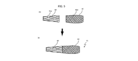
- FIG. 5 is a diagram illustrating a configuration and a method of creating a mesh member according to the second modification.
- the wire rod 82a is braided at a predetermined pitch to produce the first mesh portion 82
- the wire rod 83a is braided at a predetermined pitch to produce the second mesh portion 83.
- the relationship between the design minimum width of the opening between the first mesh portion 82 and the second mesh portion 83 is based on the design of the opening between the first mesh portion 22 and the second mesh portion 23 according to the above-described embodiment. It may be the same as the relation of the minimum width of.
- the minimum design width of the opening should be adjusted to an appropriate minimum width by appropriately adjusting the wire diameter of the wire rod 82a and the wire rod 83a to be used, the pitch of each braid of the wire rod 82a and the wire rod 83a, and the like. Can be done.
- the mesh member 81 is manufactured by joining the tip end side of the first mesh portion 82 and the base end side of the second mesh portion 83.
- a method of joining the first mesh portion 82 and the second mesh portion 83 a method of adhering the first mesh portion 82 and the second mesh portion 83 or a method of welding may be used.
- the boundary between the first mesh portion 22 and the second mesh portion 23 is the maximum width portion 21b
- the first mesh portion 22 and the second mesh portion 23 have been described.
- the boundary of the above may be set to be from the maximum width portion 21b to the proximal end side.
- the first mesh portion 22 has more wire rods 21a constituting the mesh member 21 and has higher rigidity. Since the length of the first mesh portion 22 having a relatively high rigidity is shortened by such a configuration, the mesh member 21 can have high insertability along the curvature of the inner wall of the blood vessel.
- the boundary between the first mesh portion 22 and the second mesh portion 23 may be set to be on the tip side from the maximum width portion 21b.
- the boundary between the first mesh portion 22 and the second mesh portion 23 can be appropriately determined according to the desired characteristics of the catheter 1.
- the catheter 1 in which the hollow shaft 11 includes the distal end side shaft 111, the proximal end side shaft 112, and the communication hole 113 has been described, but the catheter does not have a communication hole and is from the distal end. It may be a catheter (over-the-wire type (OTW) catheter) with a hollow shaft having a single lumen extending over the proximal end.
- OGW over-the-wire type
Landscapes
- Health & Medical Sciences (AREA)
- Life Sciences & Earth Sciences (AREA)
- Public Health (AREA)
- Engineering & Computer Science (AREA)
- Veterinary Medicine (AREA)
- Biomedical Technology (AREA)
- Heart & Thoracic Surgery (AREA)
- Animal Behavior & Ethology (AREA)
- General Health & Medical Sciences (AREA)
- Hematology (AREA)
- Anesthesiology (AREA)
- Biophysics (AREA)
- Pulmonology (AREA)
- Surgery (AREA)
- Orthopedic Medicine & Surgery (AREA)
- Vascular Medicine (AREA)
- Nuclear Medicine, Radiotherapy & Molecular Imaging (AREA)
- Medical Informatics (AREA)
- Molecular Biology (AREA)
- Media Introduction/Drainage Providing Device (AREA)
Priority Applications (2)
| Application Number | Priority Date | Filing Date | Title |
|---|---|---|---|
| PCT/JP2019/043601 WO2021090425A1 (ja) | 2019-11-07 | 2019-11-07 | カテーテル |
| JP2021554488A JPWO2021090425A1 (https=) | 2019-11-07 | 2019-11-07 |
Applications Claiming Priority (1)
| Application Number | Priority Date | Filing Date | Title |
|---|---|---|---|
| PCT/JP2019/043601 WO2021090425A1 (ja) | 2019-11-07 | 2019-11-07 | カテーテル |
Publications (1)
| Publication Number | Publication Date |
|---|---|
| WO2021090425A1 true WO2021090425A1 (ja) | 2021-05-14 |
Family
ID=75848782
Family Applications (1)
| Application Number | Title | Priority Date | Filing Date |
|---|---|---|---|
| PCT/JP2019/043601 Ceased WO2021090425A1 (ja) | 2019-11-07 | 2019-11-07 | カテーテル |
Country Status (2)
| Country | Link |
|---|---|
| JP (1) | JPWO2021090425A1 (https=) |
| WO (1) | WO2021090425A1 (https=) |
Citations (5)
| Publication number | Priority date | Publication date | Assignee | Title |
|---|---|---|---|---|
| JP2013544565A (ja) * | 2010-10-20 | 2013-12-19 | メドトロニック アーディアン ルクセンブルク ソシエテ ア レスポンサビリテ リミテ | 腎神経調節のための拡張可能なメッシュ構造を有するカテーテル器具並びに関連するシステムおよび方法 |
| JP2017077323A (ja) * | 2015-10-20 | 2017-04-27 | 朝日インテック株式会社 | カテーテル |
| WO2018193604A1 (ja) * | 2017-04-20 | 2018-10-25 | 朝日インテック株式会社 | カテーテル |
| JP2019072301A (ja) * | 2017-10-18 | 2019-05-16 | テルモ株式会社 | 回収方法 |
| WO2019198210A1 (ja) * | 2018-04-12 | 2019-10-17 | 朝日インテック株式会社 | カテーテル |
-
2019
- 2019-11-07 JP JP2021554488A patent/JPWO2021090425A1/ja not_active Withdrawn
- 2019-11-07 WO PCT/JP2019/043601 patent/WO2021090425A1/ja not_active Ceased
Patent Citations (5)
| Publication number | Priority date | Publication date | Assignee | Title |
|---|---|---|---|---|
| JP2013544565A (ja) * | 2010-10-20 | 2013-12-19 | メドトロニック アーディアン ルクセンブルク ソシエテ ア レスポンサビリテ リミテ | 腎神経調節のための拡張可能なメッシュ構造を有するカテーテル器具並びに関連するシステムおよび方法 |
| JP2017077323A (ja) * | 2015-10-20 | 2017-04-27 | 朝日インテック株式会社 | カテーテル |
| WO2018193604A1 (ja) * | 2017-04-20 | 2018-10-25 | 朝日インテック株式会社 | カテーテル |
| JP2019072301A (ja) * | 2017-10-18 | 2019-05-16 | テルモ株式会社 | 回収方法 |
| WO2019198210A1 (ja) * | 2018-04-12 | 2019-10-17 | 朝日インテック株式会社 | カテーテル |
Also Published As
| Publication number | Publication date |
|---|---|
| JPWO2021090425A1 (https=) | 2021-05-14 |
Similar Documents
| Publication | Publication Date | Title |
|---|---|---|
| US8449526B2 (en) | Torqueable soft tip medical device and method of usage | |
| EP2956197B1 (en) | Steerable medical device having multiple curve profiles | |
| JP2018533392A (ja) | 改善された支持体を備えるカテーテル構造および関連するシステム、方法、およびデバイス | |
| JP6304713B2 (ja) | バルーンカテーテル | |
| JPWO2018061598A1 (ja) | カテーテル | |
| US20220000647A1 (en) | Stent delivery apparatus | |
| US20210145465A1 (en) | Catheter | |
| JP2012045043A (ja) | 医療用器具 | |
| JP2013176488A (ja) | ガイドワイヤ | |
| JP6722350B2 (ja) | カテーテル | |
| JP2020062318A (ja) | カテーテル | |
| US11213306B2 (en) | Catheter | |
| WO2020250934A1 (ja) | カテーテル | |
| WO2021090425A1 (ja) | カテーテル | |
| CN111601632B (zh) | 导管 | |
| JP6735910B2 (ja) | カテーテル | |
| JP6633513B2 (ja) | カテーテル及びカテーテルセット | |
| JPWO2018193598A1 (ja) | カテーテル | |
| JP6882482B2 (ja) | バルーンカテーテル | |
| JP7403617B1 (ja) | カテーテル | |
| JP6844000B2 (ja) | カテーテル | |
| WO2021064825A1 (ja) | カテーテル | |
| WO2022249413A1 (ja) | カテーテル | |
| WO2023171200A1 (ja) | カテーテル | |
| WO2025244010A1 (ja) | カテーテル |
Legal Events
| Date | Code | Title | Description |
|---|---|---|---|
| 121 | Ep: the epo has been informed by wipo that ep was designated in this application |
Ref document number: 19951904 Country of ref document: EP Kind code of ref document: A1 |
|
| ENP | Entry into the national phase |
Ref document number: 2021554488 Country of ref document: JP Kind code of ref document: A |
|
| NENP | Non-entry into the national phase |
Ref country code: DE |
|
| 122 | Ep: pct application non-entry in european phase |
Ref document number: 19951904 Country of ref document: EP Kind code of ref document: A1 |