WO2021085401A1 - Fibre scintillante en plastique et son procédé de fabrication - Google Patents
Fibre scintillante en plastique et son procédé de fabrication Download PDFInfo
- Publication number
- WO2021085401A1 WO2021085401A1 PCT/JP2020/040174 JP2020040174W WO2021085401A1 WO 2021085401 A1 WO2021085401 A1 WO 2021085401A1 JP 2020040174 W JP2020040174 W JP 2020040174W WO 2021085401 A1 WO2021085401 A1 WO 2021085401A1
- Authority
- WO
- WIPO (PCT)
- Prior art keywords
- core
- clad layer
- fiber
- layer
- phosphor
- Prior art date
Links
- 239000000835 fiber Substances 0.000 title claims abstract description 127
- 229920003023 plastic Polymers 0.000 title claims abstract description 80
- 239000004033 plastic Substances 0.000 title claims abstract description 80
- 238000004519 manufacturing process Methods 0.000 title claims description 20
- OAICVXFJPJFONN-UHFFFAOYSA-N Phosphorus Chemical compound [P] OAICVXFJPJFONN-UHFFFAOYSA-N 0.000 claims abstract description 69
- 238000006243 chemical reaction Methods 0.000 claims abstract description 63
- 239000002245 particle Substances 0.000 claims abstract description 40
- 230000002093 peripheral effect Effects 0.000 claims description 40
- 239000011347 resin Substances 0.000 claims description 30
- 229920005989 resin Polymers 0.000 claims description 30
- 239000000463 material Substances 0.000 claims description 22
- 239000010419 fine particle Substances 0.000 claims description 20
- 238000000034 method Methods 0.000 claims description 14
- 238000010438 heat treatment Methods 0.000 claims description 8
- 238000005253 cladding Methods 0.000 abstract 2
- 230000001678 irradiating effect Effects 0.000 abstract 1
- 239000000178 monomer Substances 0.000 description 15
- 230000005540 biological transmission Effects 0.000 description 13
- 238000001514 detection method Methods 0.000 description 13
- 238000000295 emission spectrum Methods 0.000 description 12
- 238000000862 absorption spectrum Methods 0.000 description 10
- 229920003229 poly(methyl methacrylate) Polymers 0.000 description 9
- 239000004926 polymethyl methacrylate Substances 0.000 description 9
- 230000003287 optical effect Effects 0.000 description 7
- -1 4-t-butylphenyl Chemical group 0.000 description 6
- AIXZBGVLNVRQSS-UHFFFAOYSA-N 5-tert-butyl-2-[5-(5-tert-butyl-1,3-benzoxazol-2-yl)thiophen-2-yl]-1,3-benzoxazole Chemical compound CC(C)(C)C1=CC=C2OC(C3=CC=C(S3)C=3OC4=CC=C(C=C4N=3)C(C)(C)C)=NC2=C1 AIXZBGVLNVRQSS-UHFFFAOYSA-N 0.000 description 6
- BAPJBEWLBFYGME-UHFFFAOYSA-N Methyl acrylate Chemical compound COC(=O)C=C BAPJBEWLBFYGME-UHFFFAOYSA-N 0.000 description 6
- 239000004793 Polystyrene Substances 0.000 description 6
- YTPLMLYBLZKORZ-UHFFFAOYSA-N Thiophene Chemical compound C=1C=CSC=1 YTPLMLYBLZKORZ-UHFFFAOYSA-N 0.000 description 6
- 125000003118 aryl group Chemical group 0.000 description 6
- 229920013655 poly(bisphenol-A sulfone) Polymers 0.000 description 6
- 229920001577 copolymer Polymers 0.000 description 5
- 229920002223 polystyrene Polymers 0.000 description 5
- 238000012805 post-processing Methods 0.000 description 5
- 230000005855 radiation Effects 0.000 description 5
- 230000035945 sensitivity Effects 0.000 description 5
- PPBRXRYQALVLMV-UHFFFAOYSA-N Styrene Chemical compound C=CC1=CC=CC=C1 PPBRXRYQALVLMV-UHFFFAOYSA-N 0.000 description 4
- ZWEHNKRNPOVVGH-UHFFFAOYSA-N 2-Butanone Chemical compound CCC(C)=O ZWEHNKRNPOVVGH-UHFFFAOYSA-N 0.000 description 3
- VVQNEPGJFQJSBK-UHFFFAOYSA-N Methyl methacrylate Chemical compound COC(=O)C(C)=C VVQNEPGJFQJSBK-UHFFFAOYSA-N 0.000 description 3
- 125000005396 acrylic acid ester group Chemical group 0.000 description 3
- 230000005260 alpha ray Effects 0.000 description 3
- 229920001519 homopolymer Polymers 0.000 description 3
- 229920000642 polymer Polymers 0.000 description 3
- 239000000126 substance Substances 0.000 description 3
- 229930192474 thiophene Natural products 0.000 description 3
- 125000000391 vinyl group Chemical group [H]C([*])=C([H])[H] 0.000 description 3
- WHXSMMKQMYFTQS-BJUDXGSMSA-N (6Li)Lithium Chemical compound [6Li] WHXSMMKQMYFTQS-BJUDXGSMSA-N 0.000 description 2
- XJKSTNDFUHDPQJ-UHFFFAOYSA-N 1,4-diphenylbenzene Chemical group C1=CC=CC=C1C1=CC=C(C=2C=CC=CC=2)C=C1 XJKSTNDFUHDPQJ-UHFFFAOYSA-N 0.000 description 2
- BOBLSBAZCVBABY-WPWUJOAOSA-N 1,6-diphenylhexatriene Chemical compound C=1C=CC=CC=1\C=C\C=C\C=C\C1=CC=CC=C1 BOBLSBAZCVBABY-WPWUJOAOSA-N 0.000 description 2
- CNRNYORZJGVOSY-UHFFFAOYSA-N 2,5-diphenyl-1,3-oxazole Chemical compound C=1N=C(C=2C=CC=CC=2)OC=1C1=CC=CC=C1 CNRNYORZJGVOSY-UHFFFAOYSA-N 0.000 description 2
- YCKRFDGAMUMZLT-UHFFFAOYSA-N Fluorine atom Chemical compound [F] YCKRFDGAMUMZLT-UHFFFAOYSA-N 0.000 description 2
- LSDPWZHWYPCBBB-UHFFFAOYSA-N Methanethiol Chemical compound SC LSDPWZHWYPCBBB-UHFFFAOYSA-N 0.000 description 2
- MASVCBBIUQRUKL-UHFFFAOYSA-N POPOP Chemical compound C=1N=C(C=2C=CC(=CC=2)C=2OC(=CN=2)C=2C=CC=CC=2)OC=1C1=CC=CC=C1 MASVCBBIUQRUKL-UHFFFAOYSA-N 0.000 description 2
- 125000000319 biphenyl-4-yl group Chemical group [H]C1=C([H])C([H])=C([H])C([H])=C1C1=C([H])C([H])=C([*])C([H])=C1[H] 0.000 description 2
- 239000011248 coating agent Substances 0.000 description 2
- 238000000576 coating method Methods 0.000 description 2
- 239000013078 crystal Substances 0.000 description 2
- 230000007423 decrease Effects 0.000 description 2
- HVQAJTFOCKOKIN-UHFFFAOYSA-N flavonol Chemical compound O1C2=CC=CC=C2C(=O)C(O)=C1C1=CC=CC=C1 HVQAJTFOCKOKIN-UHFFFAOYSA-N 0.000 description 2
- 239000011737 fluorine Substances 0.000 description 2
- 229910052731 fluorine Inorganic materials 0.000 description 2
- 125000005397 methacrylic acid ester group Chemical group 0.000 description 2
- 230000004048 modification Effects 0.000 description 2
- 238000012986 modification Methods 0.000 description 2
- 239000013307 optical fiber Substances 0.000 description 2
- 150000001451 organic peroxides Chemical class 0.000 description 2
- 239000002861 polymer material Substances 0.000 description 2
- 239000000758 substrate Substances 0.000 description 2
- 229920006352 transparent thermoplastic Polymers 0.000 description 2
- 238000005491 wire drawing Methods 0.000 description 2
- MYOQALXKVOJACM-UHFFFAOYSA-N (2-methylpropan-2-yl)oxy pentaneperoxoate Chemical compound CCCCC(=O)OOOC(C)(C)C MYOQALXKVOJACM-UHFFFAOYSA-N 0.000 description 1
- JHPBZFOKBAGZBL-UHFFFAOYSA-N (3-hydroxy-2,2,4-trimethylpentyl) 2-methylprop-2-enoate Chemical compound CC(C)C(O)C(C)(C)COC(=O)C(C)=C JHPBZFOKBAGZBL-UHFFFAOYSA-N 0.000 description 1
- DPGYCJUCJYUHTM-UHFFFAOYSA-N 2,4,4-trimethylpentan-2-yloxy 2-ethylhexaneperoxoate Chemical compound CCCCC(CC)C(=O)OOOC(C)(C)CC(C)(C)C DPGYCJUCJYUHTM-UHFFFAOYSA-N 0.000 description 1
- BJEAUUFMQKUXAX-UHFFFAOYSA-N 2-phenyl-5-(2,4,6-trimethylphenyl)-3,4-dihydropyrazole Chemical compound CC1=CC(C)=CC(C)=C1C1=NN(C=2C=CC=CC=2)CC1 BJEAUUFMQKUXAX-UHFFFAOYSA-N 0.000 description 1
- VLDFXDUAENINOO-UHFFFAOYSA-N 4-methyl-2-[4-(4-methyl-5-phenyl-1,3-oxazol-2-yl)phenyl]-5-phenyl-1,3-oxazole Chemical compound CC=1N=C(C=2C=CC(=CC=2)C=2OC(=C(C)N=2)C=2C=CC=CC=2)OC=1C1=CC=CC=C1 VLDFXDUAENINOO-UHFFFAOYSA-N 0.000 description 1
- 239000004925 Acrylic resin Substances 0.000 description 1
- 229920000178 Acrylic resin Polymers 0.000 description 1
- 238000010521 absorption reaction Methods 0.000 description 1
- 238000000149 argon plasma sintering Methods 0.000 description 1
- 239000004305 biphenyl Substances 0.000 description 1
- XZCJVWCMJYNSQO-UHFFFAOYSA-N butyl pbd Chemical compound C1=CC(C(C)(C)C)=CC=C1C1=NN=C(C=2C=CC(=CC=2)C=2C=CC=CC=2)O1 XZCJVWCMJYNSQO-UHFFFAOYSA-N 0.000 description 1
- 239000012986 chain transfer agent Substances 0.000 description 1
- 239000002131 composite material Substances 0.000 description 1
- 238000010276 construction Methods 0.000 description 1
- 238000003618 dip coating Methods 0.000 description 1
- 239000002612 dispersion medium Substances 0.000 description 1
- 238000002189 fluorescence spectrum Methods 0.000 description 1
- 238000004898 kneading Methods 0.000 description 1
- 239000000203 mixture Substances 0.000 description 1
- KZCOBXFFBQJQHH-UHFFFAOYSA-N octane-1-thiol Chemical compound CCCCCCCCS KZCOBXFFBQJQHH-UHFFFAOYSA-N 0.000 description 1
- 125000000962 organic group Chemical group 0.000 description 1
- 229920000620 organic polymer Polymers 0.000 description 1
- 239000003973 paint Substances 0.000 description 1
- 239000013308 plastic optical fiber Substances 0.000 description 1
- 239000003505 polymerization initiator Substances 0.000 description 1
- 238000006116 polymerization reaction Methods 0.000 description 1
- 229920005553 polystyrene-acrylate Polymers 0.000 description 1
- 229920002102 polyvinyl toluene Polymers 0.000 description 1
- 238000012545 processing Methods 0.000 description 1
- 238000006862 quantum yield reaction Methods 0.000 description 1
- 239000011163 secondary particle Substances 0.000 description 1
- 239000007787 solid Substances 0.000 description 1
- 238000005507 spraying Methods 0.000 description 1
- GSECCTDWEGTEBD-UHFFFAOYSA-N tert-butylperoxycyclohexane Chemical compound CC(C)(C)OOC1CCCCC1 GSECCTDWEGTEBD-UHFFFAOYSA-N 0.000 description 1
- 229920001169 thermoplastic Polymers 0.000 description 1
- 229920005992 thermoplastic resin Polymers 0.000 description 1
- 239000004416 thermosoftening plastic Substances 0.000 description 1
- JFLKFZNIIQFQBS-FNCQTZNRSA-N trans,trans-1,4-Diphenyl-1,3-butadiene Chemical compound C=1C=CC=CC=1\C=C\C=C\C1=CC=CC=C1 JFLKFZNIIQFQBS-FNCQTZNRSA-N 0.000 description 1
- 238000002834 transmittance Methods 0.000 description 1
- 238000007740 vapor deposition Methods 0.000 description 1
Images


Classifications
-
- C—CHEMISTRY; METALLURGY
- C09—DYES; PAINTS; POLISHES; NATURAL RESINS; ADHESIVES; COMPOSITIONS NOT OTHERWISE PROVIDED FOR; APPLICATIONS OF MATERIALS NOT OTHERWISE PROVIDED FOR
- C09K—MATERIALS FOR MISCELLANEOUS APPLICATIONS, NOT PROVIDED FOR ELSEWHERE
- C09K11/00—Luminescent, e.g. electroluminescent, chemiluminescent materials
- C09K11/08—Luminescent, e.g. electroluminescent, chemiluminescent materials containing inorganic luminescent materials
- C09K11/58—Luminescent, e.g. electroluminescent, chemiluminescent materials containing inorganic luminescent materials containing copper, silver or gold
- C09K11/582—Chalcogenides
- C09K11/584—Chalcogenides with zinc or cadmium
-
- G—PHYSICS
- G02—OPTICS
- G02B—OPTICAL ELEMENTS, SYSTEMS OR APPARATUS
- G02B6/00—Light guides; Structural details of arrangements comprising light guides and other optical elements, e.g. couplings
- G02B6/02—Optical fibres with cladding with or without a coating
-
- B—PERFORMING OPERATIONS; TRANSPORTING
- B29—WORKING OF PLASTICS; WORKING OF SUBSTANCES IN A PLASTIC STATE IN GENERAL
- B29D—PRODUCING PARTICULAR ARTICLES FROM PLASTICS OR FROM SUBSTANCES IN A PLASTIC STATE
- B29D11/00—Producing optical elements, e.g. lenses or prisms
- B29D11/00663—Production of light guides
- B29D11/00682—Production of light guides with a refractive index gradient
-
- B—PERFORMING OPERATIONS; TRANSPORTING
- B29—WORKING OF PLASTICS; WORKING OF SUBSTANCES IN A PLASTIC STATE IN GENERAL
- B29D—PRODUCING PARTICULAR ARTICLES FROM PLASTICS OR FROM SUBSTANCES IN A PLASTIC STATE
- B29D11/00—Producing optical elements, e.g. lenses or prisms
- B29D11/00663—Production of light guides
- B29D11/00701—Production of light guides having an intermediate layer between core and cladding
-
- C—CHEMISTRY; METALLURGY
- C09—DYES; PAINTS; POLISHES; NATURAL RESINS; ADHESIVES; COMPOSITIONS NOT OTHERWISE PROVIDED FOR; APPLICATIONS OF MATERIALS NOT OTHERWISE PROVIDED FOR
- C09K—MATERIALS FOR MISCELLANEOUS APPLICATIONS, NOT PROVIDED FOR ELSEWHERE
- C09K11/00—Luminescent, e.g. electroluminescent, chemiluminescent materials
- C09K11/02—Use of particular materials as binders, particle coatings or suspension media therefor
-
- C—CHEMISTRY; METALLURGY
- C09—DYES; PAINTS; POLISHES; NATURAL RESINS; ADHESIVES; COMPOSITIONS NOT OTHERWISE PROVIDED FOR; APPLICATIONS OF MATERIALS NOT OTHERWISE PROVIDED FOR
- C09K—MATERIALS FOR MISCELLANEOUS APPLICATIONS, NOT PROVIDED FOR ELSEWHERE
- C09K11/00—Luminescent, e.g. electroluminescent, chemiluminescent materials
- C09K11/06—Luminescent, e.g. electroluminescent, chemiluminescent materials containing organic luminescent materials
-
- C—CHEMISTRY; METALLURGY
- C09—DYES; PAINTS; POLISHES; NATURAL RESINS; ADHESIVES; COMPOSITIONS NOT OTHERWISE PROVIDED FOR; APPLICATIONS OF MATERIALS NOT OTHERWISE PROVIDED FOR
- C09K—MATERIALS FOR MISCELLANEOUS APPLICATIONS, NOT PROVIDED FOR ELSEWHERE
- C09K11/00—Luminescent, e.g. electroluminescent, chemiluminescent materials
- C09K11/08—Luminescent, e.g. electroluminescent, chemiluminescent materials containing inorganic luminescent materials
- C09K11/77—Luminescent, e.g. electroluminescent, chemiluminescent materials containing inorganic luminescent materials containing rare earth metals
- C09K11/7728—Luminescent, e.g. electroluminescent, chemiluminescent materials containing inorganic luminescent materials containing rare earth metals containing europium
- C09K11/7732—Halogenides
- C09K11/7733—Halogenides with alkali or alkaline earth metals
-
- C—CHEMISTRY; METALLURGY
- C09—DYES; PAINTS; POLISHES; NATURAL RESINS; ADHESIVES; COMPOSITIONS NOT OTHERWISE PROVIDED FOR; APPLICATIONS OF MATERIALS NOT OTHERWISE PROVIDED FOR
- C09K—MATERIALS FOR MISCELLANEOUS APPLICATIONS, NOT PROVIDED FOR ELSEWHERE
- C09K11/00—Luminescent, e.g. electroluminescent, chemiluminescent materials
- C09K11/08—Luminescent, e.g. electroluminescent, chemiluminescent materials containing inorganic luminescent materials
- C09K11/77—Luminescent, e.g. electroluminescent, chemiluminescent materials containing inorganic luminescent materials containing rare earth metals
- C09K11/7728—Luminescent, e.g. electroluminescent, chemiluminescent materials containing inorganic luminescent materials containing rare earth metals containing europium
- C09K11/7734—Aluminates
-
- G—PHYSICS
- G01—MEASURING; TESTING
- G01T—MEASUREMENT OF NUCLEAR OR X-RADIATION
- G01T1/00—Measuring X-radiation, gamma radiation, corpuscular radiation, or cosmic radiation
- G01T1/16—Measuring radiation intensity
- G01T1/20—Measuring radiation intensity with scintillation detectors
- G01T1/201—Measuring radiation intensity with scintillation detectors using scintillating fibres
-
- G—PHYSICS
- G01—MEASURING; TESTING
- G01T—MEASUREMENT OF NUCLEAR OR X-RADIATION
- G01T1/00—Measuring X-radiation, gamma radiation, corpuscular radiation, or cosmic radiation
- G01T1/16—Measuring radiation intensity
- G01T1/20—Measuring radiation intensity with scintillation detectors
- G01T1/2012—Measuring radiation intensity with scintillation detectors using stimulable phosphors, e.g. stimulable phosphor sheets
-
- G—PHYSICS
- G01—MEASURING; TESTING
- G01T—MEASUREMENT OF NUCLEAR OR X-RADIATION
- G01T1/00—Measuring X-radiation, gamma radiation, corpuscular radiation, or cosmic radiation
- G01T1/16—Measuring radiation intensity
- G01T1/20—Measuring radiation intensity with scintillation detectors
- G01T1/203—Measuring radiation intensity with scintillation detectors the detector being made of plastics
-
- G—PHYSICS
- G01—MEASURING; TESTING
- G01T—MEASUREMENT OF NUCLEAR OR X-RADIATION
- G01T3/00—Measuring neutron radiation
- G01T3/06—Measuring neutron radiation with scintillation detectors
-
- G—PHYSICS
- G02—OPTICS
- G02B—OPTICAL ELEMENTS, SYSTEMS OR APPARATUS
- G02B6/00—Light guides; Structural details of arrangements comprising light guides and other optical elements, e.g. couplings
- G02B6/02—Optical fibres with cladding with or without a coating
- G02B6/036—Optical fibres with cladding with or without a coating core or cladding comprising multiple layers
- G02B6/03616—Optical fibres characterised both by the number of different refractive index layers around the central core segment, i.e. around the innermost high index core layer, and their relative refractive index difference
- G02B6/03622—Optical fibres characterised both by the number of different refractive index layers around the central core segment, i.e. around the innermost high index core layer, and their relative refractive index difference having 2 layers only
-
- G—PHYSICS
- G02—OPTICS
- G02B—OPTICAL ELEMENTS, SYSTEMS OR APPARATUS
- G02B6/00—Light guides; Structural details of arrangements comprising light guides and other optical elements, e.g. couplings
- G02B6/02—Optical fibres with cladding with or without a coating
- G02B6/02033—Core or cladding made from organic material, e.g. polymeric material
-
- G—PHYSICS
- G02—OPTICS
- G02B—OPTICAL ELEMENTS, SYSTEMS OR APPARATUS
- G02B6/00—Light guides; Structural details of arrangements comprising light guides and other optical elements, e.g. couplings
- G02B6/02—Optical fibres with cladding with or without a coating
- G02B6/036—Optical fibres with cladding with or without a coating core or cladding comprising multiple layers
- G02B6/03694—Multiple layers differing in properties other than the refractive index, e.g. attenuation, diffusion, stress properties
Definitions
- the present invention relates to a plastic scintillation fiber and a method for manufacturing the same.
- the conventional plastic scintillation fiber is a plastic fiber in which the outer peripheral surface of the core, which is a scintillator, is covered with a clad layer having a lower refractive index than the core, and is mainly used for radiation detection.
- the core is composed of a polymer material obtained by adding an organic phosphor to a base material having an aromatic ring such as polystyrene or polyvinyltoluene.
- the clad layer is composed of a low refractive index polymer material such as polymethylmethacrylate or fluorine-containing polymethylmethacrylate.
- the core base material of the scintillation fiber has an aromatic ring, and when the irradiated radiation crosses the scintillation fiber, it absorbs a part of the energy by re-radiation of secondary particles in the core and emits it as ultraviolet rays. It has the characteristic of doing. If no phosphor is added to the core base material, this ultraviolet light is self-absorbed by the core base material itself and disappears without being transmitted in the core.
- this ultraviolet ray is absorbed by the phosphor added to the core base material, and the light having a longer wavelength is re-emitted. Therefore, by selecting an appropriate phosphor, it is converted into light having a long wavelength such as blue, which is difficult to be self-absorbed by the core substrate, and transmitted in the fiber.
- the light transmitted in the fiber is detected by a detector connected to one end or both ends.
- the scintillation fiber has two functions of light emission by radiation detection and optical transmission, and is used for applications such as calculating the passing position of radiation.
- it is important how to efficiently convert the ultraviolet light emitted from the core into a long wavelength and transmit it over a long distance.
- plastic wavelength conversion fiber (WLSF: Wavelength Shifting Fiber) is often used alongside scintillation fiber.
- the wavelength conversion fiber is used in combination with, for example, a plastic scintillator that emits blue light. Grooves and holes are provided in a plate-shaped or rod-shaped plastic scintillator, and a wavelength conversion fiber that absorbs blue light and converts it into green light is embedded.
- a wavelength conversion fiber that is thin, easy to bend, and capable of long-distance transmission is preferably used.
- a large number of wavelength conversion fibers can be freely laid out up to an external photoelectric detector.
- the core of the wavelength conversion fiber is made of polystyrene or polymethylmethacrylate resin, and a phosphor for wavelength conversion is dissolved in it.
- the scintillation light incident from the external scintillator is absorbed by the phosphor in the core, the wavelength is efficiently converted, and the scintillation light is transmitted in the fiber.
- the scintillator to be combined with the wavelength conversion fiber is not limited to a plastic scintillator, but an inorganic scintillator having high sensitivity to neutrons and the like is used.
- the wavelength conversion fiber can easily collect the scintillation light emitted from a large-area or long scintillator or a special scintillator for neutron detection or the like.
- the wavelength conversion fiber transmits the wavelength-converted light in the core and can be freely connected to the photoelectric detector.
- the inorganic scintillator has an attenuation length of several mm and is not highly transparent, and cannot transmit emitted light (that is, scintillation light) over a long distance. Further, since there are restrictions on the crystal size, it is difficult to perform optical transmission to the photoelectric detector by an inorganic scintillator.
- Patent Documents 2 and 3 a sheet in which fine particles obtained by crushing an inorganic scintillator are dispersed in a transparent resin has been developed for detecting neutrons and heavy particle beams.
- the difference in refractive index between the inorganic scintillator and the transparent resin is large, transparency cannot be ensured, and the sheet itself cannot efficiently transmit light to the photoelectric detector.
- the wavelength conversion fiber is placed along the end face and surface of the scintillator, and the wavelength conversion fiber is used for optical transmission to the photoelectric detector.
- the detected light can be transmitted over a longer distance.
- a large number of post-processings in which a scintillator and a wavelength conversion fiber are combined are required. Become.
- the core itself is required to have high transparency because the core itself emits scintillation light and optical transmission is performed to the photoelectric detector. Therefore, it is not possible to obtain a plastic scintillation fiber for detecting a neutron beam or a heavy particle beam by including a material that emits scintillation light by irradiation with a neutron beam or a heavy particle beam in the core.
- the scintillation light irradiated from the external scintillator is wavelength-converted in the core and transmitted through the core, so that the core is required to have high transparency. Therefore, it is not possible to obtain a plastic scintillation fiber for detecting a neutron beam or a heavy particle beam by including a material that emits scintillation light by irradiation with a neutron beam or a heavy particle beam in the core.
- a conventional scintillation detector using a wavelength conversion fiber requires post-processing that combines a scintillator and a wavelength conversion fiber. Further, in the case of image detection, it is necessary to separate and combine one scintillator for each of a large number of wavelength conversion fibers, which makes processing extremely difficult.
- the present invention has been made in view of such circumstances, and an object of the present invention is to provide a plastic scintillation fiber capable of detecting at least one of a neutron beam and a heavy particle beam and having excellent productivity.
- the plastic scintillation fiber according to one aspect of the present invention is The outermost layer containing a material that emits scintillation light by irradiation of at least one of neutron beam and heavy particle beam, A core provided inside the outermost layer and containing at least one type of phosphor that absorbs the scintillation light and converts the wavelength into a long wavelength. A clad layer that covers the outer peripheral surface of the core and has a lower refractive index than that of the core is provided.
- the wavelength conversion fiber including the core and the clad layer and the outermost peripheral layer covering the outer peripheral surface of the wavelength conversion fiber are integrally formed.
- scintillation light is generated in the outermost peripheral layer by irradiation with neutron rays or heavy particle beams, and the scintillation light is absorbed by the internal core to convert the wavelength and optical transmission. To do. Therefore, neutron rays and heavy particle beams, which are difficult to detect with conventional plastic scintillation fibers, can be detected. Further, since the wavelength conversion fiber including the core and the clad layer and the outermost peripheral layer covering the outer peripheral surface of the wavelength conversion fiber are integrally formed, post-processing for combining the scintillator and the wavelength conversion fiber, which has been conventionally required, is unnecessary. It becomes. That is, it is possible to provide a highly productive plastic scintillation fiber capable of detecting at least one of a neutron beam and a heavy particle beam.
- the material may be fine particles of an inorganic fluorescent substance, and the outermost peripheral layer may be made of a transparent resin in which the fine particles are dispersed. It can detect neutron rays and heavy particle beams with high sensitivity.
- wavelength conversion fiber and the outermost peripheral layer may be integrally formed by wire drawing. Productivity is improved.
- the clad layer may have a multi-clad structure including an inner clad layer and an outer clad layer that covers the outer peripheral surface of the inner clad layer and has a refractive index lower than that of the inner clad layer. .. The total reflection angle becomes wider and the light emission becomes higher.
- the method for manufacturing a plastic scintillation fiber according to one aspect of the present invention is as follows.
- the outermost layer containing a phosphor that emits scintillation light by irradiation of at least one of neutron beam and heavy particle beam,
- a core provided inside the outermost layer and containing at least one type of phosphor that absorbs the scintillation light and converts the wavelength into a long wavelength.
- a method for producing a plastic scintillation fiber which covers the outer peripheral surface of the core and includes a clad layer having a refractive index lower than that of the core.
- the method for manufacturing a plastic scintillation fiber according to one aspect of the present invention is as follows.
- the outermost layer containing a phosphor that emits scintillation light by irradiation of at least one of neutron beam and heavy particle beam,
- a core having a high refractive index which is provided inside the outermost layer and contains at least one kind of phosphor that absorbs the scintillation light and converts the wavelength into a long wavelength.
- a method for producing a plastic scintillation fiber which covers the outer peripheral surface of the core and includes a clad layer having a refractive index lower than that of the core.
- the outermost peripheral layer is coated on the surface of the clad layer.
- a plastic scintillation fiber capable of detecting at least one of a neutron beam and a heavy particle beam and having excellent productivity.
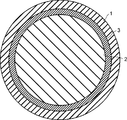
- FIG. It is sectional drawing of the plastic scintillation fiber which concerns on Embodiment 1.
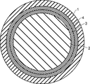
- FIG. It is sectional drawing of the plastic scintillation fiber which concerns on the modification of Embodiment 1.
- FIG. It is a perspective view which shows the manufacturing method of the plastic scintillation fiber which concerns on Embodiment 1.
- FIG. It is a perspective view which shows the application example of the scintillation fiber which concerns on Embodiment 1.
- FIG. It is a graph which shows the emission spectrum of the neutron phosphor LiCaAlF 6 : Eu, and the absorption and emission spectrum of the wavelength conversion phosphor BBOT.
- FIG. 1 is a cross-sectional view of the plastic scintillation fiber according to the first embodiment.
- the plastic scintillation fiber according to the first embodiment includes an outermost peripheral layer 1, a core 2, and a clad layer 3.
- the outermost layer 1 is made of a resin containing a material that scintillates and emits light by at least one of a neutron beam and a heavy particle beam (for example, an alpha ray).
- the outermost layer 1 is made of a transparent resin (transparent organic polymer) in which fine particles of an inorganic phosphor (inorganic scintillator) that emits scintillation by neutron rays or heavy particle beams are dispersed.
- the outermost peripheral layer 1 may emit sufficient light and be transparent to the extent that scintillation light penetrates the clad layer 3 and enters the core 2 in the center, and high transparency is not required, but it is as transparent as possible. The thinner one is desirable. Even if the outermost layer 1 which is a scintillator layer has low transparency, long-distance transmission is possible if the core 2 at the center, which is responsible for optical transmission, has high transparency.
- the core 2 is provided inside the outermost layer 1, and is made of a transparent resin having a high refractive index containing at least one kind of phosphor that absorbs the scintillation light generated in the outermost layer 1 and converts it into a longer wavelength.
- the refractive index of the transparent resin constituting the core 2 is preferably 1.5 or more.
- the clad layer 3 covers the outer peripheral surface of the core 2 and is made of a transparent resin having a lower refractive index than that of the core 2.
- the wavelength conversion fiber composed of the core 2 and the clad layer 3 and the outermost peripheral layer 1 covering the outer peripheral surface of the wavelength conversion fiber are integrally formed.
- the transparency of the clad layer 3 is as important as the transparency of the core 2.
- the transparency of the outermost layer 1 is not so important.
- the thickness of the clad layer 3 is preferably 3 ⁇ m to 100 ⁇ m, which is sufficiently thicker than the depth of the evanescent wave in which the transmitted light seeps from the core 2 to the clad layer 3.
- the refractive indexes of the clad layer 3 and the outermost peripheral layer 1 may be the same, or the same transparent resin may be used.
- the core 2 may include a second phosphor for further wavelength conversion in order to match the wavelength sensitivity of a photoelectric detector such as a photomultiplier tube (PMT) or an avalanche photodiode (APD).
- a photoelectric detector such as a photomultiplier tube (PMT) or an avalanche photodiode (APD). The details of the phosphor will be described later.
- the plastic scintillation fiber according to the first embodiment scintillation light is generated in the outermost peripheral layer 1 due to irradiation with neutron rays or heavy particle beams, and the scintillation light is absorbed by the internal core 2 to convert the wavelength and light. To transmit. Therefore, neutron rays and heavy particle beams, which are difficult to detect with conventional plastic scintillation fibers, can be detected with high sensitivity. That is, the plastic scintillation fiber according to the first embodiment is a composite type plastic optical fiber having both a neutron beam and heavy particle beam scintillation function and a wavelength conversion function.
- the wavelength conversion fiber composed of the core 2 and the clad layer 3 and the outermost peripheral layer 1 covering the outer peripheral surface of the wavelength conversion fiber are integrally formed. Therefore, post-processing that combines a scintillator and a wavelength conversion fiber, which has been required in the past, is not required, and productivity can be dramatically improved and costs can be reduced as compared with the conventional case.
- FIG. 2 is a cross-sectional view of a plastic scintillation fiber according to a modified example of the first embodiment.
- the plastic scintillation fiber according to the modified example includes a clad layer 3 as an inner clad layer and a clad layer 4 as an outer clad layer. That is, the clad layer has a multi-clad structure including an inner clad layer (clad layer 3) and an outer clad layer (clad layer 4).
- the clad layer 4 covers the outer peripheral surface of the clad layer 3 and is made of a transparent resin having a lower refractive index than that of the clad layer 3.
- the re-emitted light whose wavelength is converted in the core 2 is radiated isotropically in a solid angle in the core 2. Therefore, only light within the total reflection angle based on the difference in refractive index between the core 2 and the clad layer 3 or the clad layer 4 can be transmitted in the fiber direction. Since the plastic scintillation fiber according to the modified example includes the clad layer 4 having a low refractive index in addition to the clad layer 3, the total reflection angle is wider (the numerical aperture NA is larger) than the plastic scintillation fiber of FIG. High light emission.
- the outermost layer 1 which is a scintillator layer is made of a resin containing a material (fluorescent substance) that emits scintillation light by irradiation with at least one of a neutron beam and a heavy particle beam (alpha ray, etc.).
- the outermost layer 1 is made of a transparent resin in which fine particles of an inorganic phosphor that emits scintillation by neutron rays or heavy particle beams are uniformly or non-uniformly dispersed.
- the transparent resin constituting the outermost outer layer 1 is preferably thermoplastic so that it can be thinly drawn by heating.
- a transparent resin any one of a methacrylic acid ester monomer group represented by methyl methacrylate, an acrylic acid ester monomer group represented by methyl acrylate, and an aromatic monomer group having a vinyl group represented by styrene.
- a homopolymer or a copolymer composed of the above is preferable.
- the refractive index of the transparent resin constituting the outermost outermost layer 1 is not limited from the viewpoint of optical transmission performance, but it is preferably close to the refractive index of the inorganic phosphor to be dispersed. This is because if the difference in refractive index between the inorganic phosphor to be dispersed and the transparent resin as the dispersion medium is large, light scattering becomes large and the scintillation light generated in the outermost peripheral layer 1 does not effectively reach the core 2.
- an inorganic phosphor as described in Patent Documents 1 and 2 may be preferable because it has no sensitivity to gamma rays and selectively emits light only by neutron rays.
- the outermost layer 1 is formed by dispersing 1 to 30% by mass of fine particles of LiCaAlF 6 : Eu, an inorganic phosphor that contains lithium 6 and is doped with Eu and scintillates and emits light by neutron rays.
- the transparent resin for dispersing the fine particles of the inorganic phosphor can be preferably selected from the same as the core 2 or the clad layers 3 and 4.
- the outermost layer 1 scintillates ultraviolet light of 350 to 400 nm by neutron rays.
- the outermost layer 1 is a transparent resin in which fine particles of the inorganic phosphor ZnS: Ag that scintillates and emits light by heavy particle beams (alpha rays, etc.) are dispersed.
- the transparent resin for dispersing the fine particles of the inorganic phosphor can also be preferably selected from the same as the core 2 or the clad layers 3 and 4.
- the outermost layer 1 emits visible light of 400 to 500 nm by heavy particle beams.
- the particle size of the inorganic phosphor dispersed in the transparent resin is preferably 0.1 to 100 ⁇ m, more preferably 1 to 10 ⁇ m.
- the concentration of the inorganic phosphor to be dispersed is preferably 1 to 50% by mass, more preferably 5 to 30% by mass. If the concentration is too low, the luminous efficiency of the neutron beam or heavy particle beam in the outermost layer 1 deteriorates. If the concentration is too high, it becomes difficult to disperse in the transparent resin, or it becomes difficult to draw a line by heating.
- the inorganic phosphor to be dispersed is appropriately selected depending on the neutron beam or heavy particle beam to be detected, and is not limited to the above. Further, the particle size and concentration of the inorganic phosphor are also appropriately selected depending on the detection performance, the difficulty of production, and the like, and are not limited to the above. Further, the transparent resin to be dispersed is also appropriately selected depending on the dispersibility, ease of production, and the like, and is not limited to the above.
- a polymer composed of an aromatic monomer having a vinyl group has a high refractive index and is preferable.
- the difference in refractive index between the core 2 and the clad layer 3 becomes large, and the total reflection angle becomes wide. That is, among the wavelength-converted light in the core 2, the light having a wider angle can be transmitted, so that a scintillation fiber having higher light emission can be obtained.
- the wavelength conversion phosphor contained in the core 2 is an organic phosphor having an aromatic ring and a structure capable of resonating, and it is preferable that a single molecule is dissolved in the core 2.
- Typical phosphors include 2- (4-t-butylphenyl) -5- (4-biphenyl) -1,3,4-oxadiazole (b-PBD), 2-which absorbs 250 to 350 nm.
- BDB 4,4'-bis- (2,5-dimethylstyryl) -diphenyl
- BBOT 2,5-bis- (5-t-butyl-benzoxazoyl) thiophene
- POPOP 4-Bis- (2- (5-phenyloxazolyl)) Benzene
- DMPOPOP 1,4-Bis- (4-Methyl-5-Phenyl-2-oxazolyl) Benzene
- DMPOPOP 1,4- Diphenyl-1,3-butadiene
- DPH 1,6-diphenyl-1,3,5-hexatriene
- HOSTASOLE YELLOW 3G that absorbs 400 to 500 nm
- MACROLEX FLUORESCENT YELLOW 10GN Kayaset Yellow SF-G
- LUMOGEN F ORANGE 240 that absorbs 500 to 600 nm
- LUMOGEN F RED 300 and the like.
- the absorption spectrum of the wavelength-converted phosphor contained in the core 2 and the emission spectrum of the inorganic phosphor contained in the outermost layer 1 have a large overlap.
- the above-mentioned wavelength conversion phosphor may be used alone, or a plurality of wavelength conversion phosphors may be used in combination.
- the quantum yield is high and the overlap between the absorption spectrum and the emission spectrum is small (the Stokes shift is large).
- a wavelength conversion phosphor that emits light at a longer wavelength is preferable, and two or more kinds may be used in combination as appropriate.
- the wavelength conversion phosphor is preferably soluble in the transparent resin constituting the core 2.
- the concentration of the wavelength conversion phosphor is preferably 50 to 10000 ppm, more preferably 100 to 1000 ppm, in terms of mass concentration, whether it is used alone or in combination of two or more. If the density is too low, the scintillation light from the outermost layer 1 cannot be efficiently absorbed by the core 2. On the contrary, if the concentration is too high, the influence of self-absorption of the phosphor itself becomes large, the wavelength conversion efficiency decreases, the transmittance for the converted light decreases, and the attenuation length deteriorates.
- the material used for the clad layer 3 is not limited as long as it is a transparent resin having a lower refractive index than the core 2.
- a homopolymer or a copolymer made from the above is preferable.
- the material used for the clad layer 4 may be a transparent resin having a lower refractive index than that of the clad layer 3. It can be selected from the monomer group of the clad layer 3 and the like. In particular, it is preferable to select from the group of fluorine-containing monomers having a low refractive index.
- an organic peroxide or an azo compound may be added as a polymerization initiator.
- Typical organic peroxides include 1,1,3,3-tetramethylbutylperoxy-2-ethylhexanoate, n-butyl-4,4-bis (t-butylperoxy) valerate, 1, Examples thereof include 1-bis (t-butylperoxy) cyclohexane, but the present invention is not particularly limited as long as it generates radicals by heat or light irradiation.
- mercaptan may be added as a chain transfer agent for adjusting the molecular weight.
- a typical mercaptan is octyl mercaptan, but there is no particular limitation as long as it has an R-SH structure (where R represents an organic group).
- FIG. 3 is a perspective view showing a method of manufacturing the plastic scintillation fiber according to the first embodiment.
- FIG. 3 shows a base material (preform) for manufacturing the plastic scintillation fiber shown in FIG.
- the first cylinder 11 is a cylinder made of a thermoplastic resin in which fine particles of an inorganic phosphor that emits scintillation by at least one of a neutron beam and a heavy particle beam are dispersed.
- the first cylindrical body 11 constitutes the outermost peripheral layer 1 after the drawing process. Details of the method for manufacturing the first cylindrical body 11 will be described later.
- the rod 12 is a cylinder made of a transparent thermoplastic resin in which at least one kind of phosphor that absorbs scintillation light and converts the wavelength into a long wavelength is dissolved.
- the rod 12 constitutes the core 2 after the wire drawing process.
- the second cylindrical body 13 has a refractive index lower than that of the rod 12, and is a cylindrical body made of a transparent thermoplastic resin.
- the second cylindrical body 13 constitutes the clad layer 3 after the drawing process.
- FIG. 3 shows a state in which the rod 12 is being inserted into the second cylindrical body 13.
- the plastic scintillation fiber according to the first embodiment can be obtained by drawing a wire to, for example, an outer diameter of 1 mm while heating the tip of the produced preform.
- a gap is formed between the first cylindrical body 11, the second cylindrical body 13, and the rod 12, but since the line drawing process is performed under reduced pressure, the core 2 and the clad layer are formed. 3 and the outermost peripheral layer 1 are in close contact with each other and integrally formed.
- the plastic scintillation fiber according to the modified example shown in FIG. 2 can also be manufactured by the same manufacturing method.
- a scintillator layer (outermost peripheral layer 1) that emits light by a neutron beam or a heavy particle beam is integrally formed on the outer peripheral surface of a wavelength conversion fiber (core 2 and clad layer 3). .. Therefore, the plastic scintillation fiber can detect neutron rays and heavy particle beams and can transmit light. That is, the plastic scintillation fiber alone has the functions of a conventional scintillator and a wavelength conversion fiber.
- the scintillator layer (outermost peripheral layer 1) may be integrally formed by coating (including coating) such as vapor deposition, dip coating, and spray coating.
- coating including coating
- a material fluorescent substance that emits scintillation light by irradiation with at least one of neutron beam and heavy particle beam (alpha ray, etc.) can be added at a higher concentration.
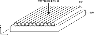
- FIG. 4 is a perspective view showing an application example of the plastic scintillation fiber according to the first embodiment.
- the plastic scintillation fiber PSF according to the first embodiment is arranged in an array on the substrate.
- the right-handed xyz orthogonal coordinates shown in FIG. 4 are for convenience to explain the positional relationship of the components.
- the z-axis positive direction is vertically upward
- the xy plane is a horizontal plane.
- a photoelectric detector such as a photomultiplier tube is connected to each plastic scintillation fiber PSF (not shown), and the transmitted light can be detected.
- one-dimensional image detection becomes possible, for example, with a resolution of 1 mm.
- the resolution is equal to the diameter of the plastic scintillation fiber PSF.
- such an array of plastic scintillation fiber PSFs is provided in two stages and arranged so as to be orthogonal to each other and stacked one above the other, two-dimensional image detection can be realized.
- LiCaAlF 6 An inorganic phosphor that contains lithium 6 and is doped with Eu and scintillates with neutron rays. After kneading fine particles of Eu with polymethyl methacrylate, a cylindrical body for the outermost layer having an outer diameter of 50 mm and an inner diameter of 40 mm (Fig. 3) The first cylindrical body 11) of the above was molded. The average particle size of the fine particles was 6.2 ⁇ m, and the concentration of the fine particles was 22% by mass.
- a core rod (rod 12 in FIG. 3) having a diameter of 32 mm made of polystyrene (refractive index 1.59) and a cylinder for a clad layer having an outer diameter of 38 mm and an inner diameter of 34 mm made of polymethylmethacrylate (refractive index 1.49).
- the second cylindrical body 13) of FIG. 3 was prepared. 2,5-Bis- (5-t-butyl-benzoxazoyl) thiophene (BBOT) as a wavelength conversion phosphor was dissolved in the core rod at a concentration of 200 mass ppm.
- BBOT 2,5-Bis- (5-t-butyl-benzoxazoyl) thiophene
- the cylinder for the clad layer was inserted inside the cylinder for the outermost layer, and the rod for the core was inserted inside the cylinder for the clad layer to prepare a preform. While heating the tip of this preform, an integral wire was drawn so that the outer diameter was 1 mm under reduced pressure to obtain a plastic scintillation fiber according to Example 1.
- This plastic scintillation fiber has the cross-sectional structure shown in FIG. The outer diameter was 1000 ⁇ m, the diameter of the clad layer 3 was 770 ⁇ m, the diameter of the core 2 was 680 ⁇ m, the thickness of the outermost peripheral layer 1 was 115 ⁇ m, and the thickness of the clad layer 3 was 45 ⁇ m.
- FIG. 5 is a graph showing the emission spectrum of the neutron phosphor LiCaAlF 6 : Eu and the absorption and emission spectra of the wavelength conversion phosphor BBOT. As shown in FIG. 5, there is a large overlap between the scintillation emission spectrum of the neutron phosphor and the absorption spectrum of the wavelength conversion phosphor. When a neutron beam was incident on the plastic scintillation fiber according to Example 1, a sufficient amount of light could be observed at the tip 10 m away.
- Example 2 In the same manner as in Example 1, a cylindrical body for the outermost peripheral layer (first cylindrical body 11 in FIG. 3) having an outer diameter of 50 mm and an inner diameter of 40 mm was formed. Further, as in Example 1, a core rod (rod 12 in FIG. 3) having a diameter of 28 mm made of polystyrene (refractive index 1.59) and an outer diameter 33 mm made of polymethylmethacrylate (refractive index 1.49), A cylindrical body for an inner clad layer having an inner diameter of 30 mm (second cylindrical body 13 in FIG. 3) was prepared. BBOT was dissolved in the core rod as a wavelength conversion phosphor at a concentration of 300 mass ppm.
- Example 2 a cylinder (not shown) for an outer clad layer having an outer diameter of 38 mm and an inner diameter of 35 mm made of a copolymer of a fluorinated monomer such as perfluoroalkyl acrylate (refractive index 1.42) was prepared.
- the cylinder for the outer clad layer constitutes the clad layer 4 shown in FIG. 2 after the drawing process.
- the preform is produced by inserting the cylinder for the outer clad layer inside the cylinder for the outermost layer, inserting the cylinder for the inner clad layer inside, and inserting the rod for the core inside the cylinder. did.
- This plastic scintillation fiber has the cross-sectional structure shown in FIG.
- the outer diameter is 1000 ⁇ m
- the outer diameter of the clad layer 4 is 754 ⁇ m
- the outer diameter of the clad layer 3 is 682 ⁇ m
- the diameter of the core 2 is 612 ⁇ m
- the thickness of the outermost peripheral layer 1 is 123 ⁇ m
- the thickness of the clad layer 4 is 36 ⁇ m
- the clad layer 3 The thickness of was 35 ⁇ m.
- Example 2 When a neutron beam was incident on the plastic scintillation fiber according to Example 2, a light amount about 30% higher than that of Example 1 could be observed at the tip 10 m away. Although the diameter of the core 2 was smaller than that of the first embodiment, it is considered that the total reflection angle was widened and the light emission was higher due to the provision of the clad layer 4 having a lower refraction.
- Inorganic phosphor ZnS Ag fine particles that emit light by scintillation by heavy particle beams such as alpha rays are kneaded with polymethylmethacrylate, and then a cylinder for the outermost layer having an outer diameter of 50 mm and an inner diameter of 40 mm (the first cylinder in FIG. 3). 11) was molded. The average particle size of the fine particles was 5.3 ⁇ m, and the concentration of the fine particles was 25% by mass.
- a core rod (rod 12 in FIG. 3) having a diameter of 32 mm made of polystyrene (refractive index 1.59) and a cylinder for a clad layer having an outer diameter of 38 mm and an inner diameter of 34 mm made of polymethylmethacrylate (refractive index 1.49).
- the second cylindrical body 13) of FIG. 3 was prepared.
- HOSTASOLE YELLOW 3G was dissolved in the core rod as a wavelength conversion phosphor at a concentration of 300 mass ppm.
- the cylinder for the clad layer was inserted inside the cylinder for the outermost layer, and the rod for the core was inserted inside the cylinder for the clad layer to prepare a preform. While heating the tip of this preform, an integral wire was drawn so that the outer diameter was 1 mm under reduced pressure to obtain a plastic scintillation fiber according to Example 3.
- This plastic scintillation fiber has the cross-sectional structure shown in FIG. The outer diameter was 1000 ⁇ m, the diameter of the clad layer 3 was 770 ⁇ m, the diameter of the core 2 was 680 ⁇ m, the thickness of the outermost peripheral layer 1 was 115 ⁇ m, and the thickness of the clad layer 3 was 45 ⁇ m.
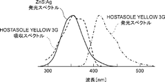
- FIG. 6 is a graph showing the emission spectrum of the inorganic phosphor ZnS: Ag and the absorption and emission spectra of the wavelength conversion phosphor HOSTASOLE YELLOW 3G.
- the scintillation emission spectrum of the inorganic phosphor and the absorption spectrum of the wavelength conversion phosphor have a large overlap.
- alpha rays were incident on the plastic scintillation fiber according to Example 3, a sufficient amount of light could be observed at the tip 10 m away.
- BBOT 2,5-bis- (5-t-butyl-benzoxazoyl) thiophene
- a wavelength conversion fiber having a diameter of 770 ⁇ m composed of a clad layer 3 made of polymethylmethacrylate (refractive index 1.49) having a thickness of 45 ⁇ m was prepared.
- a paint prepared by dissolving 7% by mass of an acrylic resin and 3% by mass of fine particles of the neutron phosphor LiCaAlF 6 : Eu in 90% by mass of methyl ethyl ketone was applied to the surface of the wavelength conversion fiber by a dip method and dried.
- the outermost layer 1 having a thickness of 115 ⁇ m was formed, and the plastic scintillation fiber having an outer diameter of 1000 ⁇ m according to Example 4 was obtained.
- a neutron beam was incident on the plastic scintillation fiber according to Example 4, a sufficient amount of light could be observed at the tip 10 m away.
Abstract
La présente invention concerne une fibre scintillante en plastique comprenant : une couche externe (1) comprenant un phosphore qui émet une lumière scintillante par irradiation de faisceaux de neutrons et/ou de faisceaux de particules lourdes ; un noyau (2) disposé à l'intérieur de la couche externe (1) et comprenant au moins un type de phosphore qui absorbe et convertit la lumière scintillante en une lumière de longueur d'onde supérieure ; et une couche de gainage (3) qui recouvre la surface externe du noyau (2) et possède un indice de réfraction inférieur à celui du noyau (2). Le noyau (2) et la couche de gainage (3) constituent des fibres de conversion de longueur d'onde et sont formés d'un seul tenant avec la couche externe (1) qui recouvre la surface externe des fibres de conversion de longueur d'onde.
Priority Applications (4)
| Application Number | Priority Date | Filing Date | Title |
|---|---|---|---|
| JP2021553616A JPWO2021085401A1 (fr) | 2019-10-31 | 2020-10-27 | |
| US17/773,278 US20230040697A1 (en) | 2019-10-31 | 2020-10-27 | Plastic scintillating fiber and its manufacturing method |
| CN202080074049.5A CN114600013A (zh) | 2019-10-31 | 2020-10-27 | 塑料闪烁光纤及其制造方法 |
| EP20881303.0A EP4053856A4 (fr) | 2019-10-31 | 2020-10-27 | Fibre scintillante en plastique et son procédé de fabrication |
Applications Claiming Priority (2)
| Application Number | Priority Date | Filing Date | Title |
|---|---|---|---|
| JP2019198101 | 2019-10-31 | ||
| JP2019-198101 | 2019-10-31 |
Publications (1)
| Publication Number | Publication Date |
|---|---|
| WO2021085401A1 true WO2021085401A1 (fr) | 2021-05-06 |
Family
ID=75715988
Family Applications (1)
| Application Number | Title | Priority Date | Filing Date |
|---|---|---|---|
| PCT/JP2020/040174 WO2021085401A1 (fr) | 2019-10-31 | 2020-10-27 | Fibre scintillante en plastique et son procédé de fabrication |
Country Status (5)
| Country | Link |
|---|---|
| US (1) | US20230040697A1 (fr) |
| EP (1) | EP4053856A4 (fr) |
| JP (1) | JPWO2021085401A1 (fr) |
| CN (1) | CN114600013A (fr) |
| WO (1) | WO2021085401A1 (fr) |
Citations (8)
| Publication number | Priority date | Publication date | Assignee | Title |
|---|---|---|---|---|
| JPH09236669A (ja) * | 1996-03-01 | 1997-09-09 | Tohoku Electric Power Co Inc | ファイバ型放射線検出器 |
| JP2011141239A (ja) | 2010-01-08 | 2011-07-21 | Japan Atomic Energy Agency | ピクセル型二次元イメージ検出器 |
| JP2012126854A (ja) | 2010-12-16 | 2012-07-05 | Tokuyama Corp | 中性子用シンチレーターおよび中性子検出器 |
| JP2015072227A (ja) | 2013-10-04 | 2015-04-16 | 独立行政法人日本原子力研究開発機構 | 中性子検出器 |
| JP2015513075A (ja) * | 2012-02-14 | 2015-04-30 | アメリカン サイエンス アンド エンジニアリング,インコーポレイテッドAmerican Science and Engineering,Inc. | 波長シフトファイバ結合シンチレーション検出器を用いるx線検査 |
| JP2018200172A (ja) * | 2017-05-25 | 2018-12-20 | 株式会社クラレ | プラスチック波長変換ファイバ及びその製造方法 |
| JP2019148538A (ja) * | 2018-02-28 | 2019-09-05 | 株式会社クラレ | 高線量場プラスチックシンチレーションファイバー及びその製造方法 |
| JP2019198101A (ja) | 2011-09-09 | 2019-11-14 | エルジー エレクトロニクス インコーポレイティド | インタ予測方法及びその装置 |
Family Cites Families (6)
| Publication number | Priority date | Publication date | Assignee | Title |
|---|---|---|---|---|
| CN102183812A (zh) * | 2011-02-21 | 2011-09-14 | 北京大学 | 一种闪烁—移波光纤及快中子转换屏 |
| CN110146913A (zh) * | 2019-05-10 | 2019-08-20 | 南开大学 | 一种用于超长距离辐射传感的双包层闪烁光纤结构 |
| JP7428714B2 (ja) * | 2019-07-30 | 2024-02-06 | 株式会社クラレ | プラスチック波長変換ファイバ |
| CN116261677A (zh) * | 2020-09-16 | 2023-06-13 | 株式会社可乐丽 | 塑料闪烁光纤及其制造方法 |
| WO2022079956A1 (fr) * | 2020-10-15 | 2022-04-21 | 株式会社クラレ | Fibre scintillante en plastique et son procédé de fabrication |
| US20230391030A1 (en) * | 2020-10-15 | 2023-12-07 | Kuraray Co., Ltd. | Plastic scintillating fiber and its manufacturing method |
-
2020
- 2020-10-27 EP EP20881303.0A patent/EP4053856A4/fr active Pending
- 2020-10-27 JP JP2021553616A patent/JPWO2021085401A1/ja active Pending
- 2020-10-27 WO PCT/JP2020/040174 patent/WO2021085401A1/fr unknown
- 2020-10-27 US US17/773,278 patent/US20230040697A1/en active Pending
- 2020-10-27 CN CN202080074049.5A patent/CN114600013A/zh active Pending
Patent Citations (8)
| Publication number | Priority date | Publication date | Assignee | Title |
|---|---|---|---|---|
| JPH09236669A (ja) * | 1996-03-01 | 1997-09-09 | Tohoku Electric Power Co Inc | ファイバ型放射線検出器 |
| JP2011141239A (ja) | 2010-01-08 | 2011-07-21 | Japan Atomic Energy Agency | ピクセル型二次元イメージ検出器 |
| JP2012126854A (ja) | 2010-12-16 | 2012-07-05 | Tokuyama Corp | 中性子用シンチレーターおよび中性子検出器 |
| JP2019198101A (ja) | 2011-09-09 | 2019-11-14 | エルジー エレクトロニクス インコーポレイティド | インタ予測方法及びその装置 |
| JP2015513075A (ja) * | 2012-02-14 | 2015-04-30 | アメリカン サイエンス アンド エンジニアリング,インコーポレイテッドAmerican Science and Engineering,Inc. | 波長シフトファイバ結合シンチレーション検出器を用いるx線検査 |
| JP2015072227A (ja) | 2013-10-04 | 2015-04-16 | 独立行政法人日本原子力研究開発機構 | 中性子検出器 |
| JP2018200172A (ja) * | 2017-05-25 | 2018-12-20 | 株式会社クラレ | プラスチック波長変換ファイバ及びその製造方法 |
| JP2019148538A (ja) * | 2018-02-28 | 2019-09-05 | 株式会社クラレ | 高線量場プラスチックシンチレーションファイバー及びその製造方法 |
Non-Patent Citations (1)
| Title |
|---|
| See also references of EP4053856A4 |
Also Published As
| Publication number | Publication date |
|---|---|
| US20230040697A1 (en) | 2023-02-09 |
| EP4053856A4 (fr) | 2023-11-29 |
| CN114600013A (zh) | 2022-06-07 |
| JPWO2021085401A1 (fr) | 2021-05-06 |
| EP4053856A1 (fr) | 2022-09-07 |
Similar Documents
| Publication | Publication Date | Title |
|---|---|---|
| WO2018043383A1 (fr) | Fibre à scintillation en plastique à champ de rayonnement à haute dose et son procédé de fabrication | |
| US8314399B2 (en) | Radiation detector with optical waveguide and neutron scintillating material | |
| US20200191980A1 (en) | Plastic scintillating fiber and method for producing same | |
| WO2011044266A2 (fr) | Système et procédé pour détecter un rayonnement cible | |
| JP6963547B2 (ja) | プラスチックシンチレーションファイバ及びその製造方法 | |
| JP6833611B2 (ja) | プラスチック波長変換ファイバ及びその製造方法 | |
| WO2022059298A1 (fr) | Fibre de scintillation en plastique et son procédé de fabrication | |
| WO2022079957A1 (fr) | Fibre scintillante en plastique et son procédé de fabrication | |
| WO2022079956A1 (fr) | Fibre scintillante en plastique et son procédé de fabrication | |
| JP7048349B2 (ja) | 高線量場プラスチックシンチレーションファイバー及びその製造方法 | |
| WO2021085401A1 (fr) | Fibre scintillante en plastique et son procédé de fabrication | |
| CN105137472B (zh) | 基于表面共振腔结构的定向发射闪烁体器件 | |
| JP2010169674A (ja) | 放射線検出器 | |
| WO2021020478A1 (fr) | Fibre de conversion de longueur d'onde en plastique | |
| WO2020145278A1 (fr) | Fibre scintillante en plastique pour détecter un rayonnement à faible pénétration | |
| WO2007106333A2 (fr) | Scintillateur a meilleur captage de lumiere | |
| US10234571B1 (en) | Radiation detector | |
| WO2022154071A1 (fr) | Fibre de conversion de longueur d'onde en plastique et son procédé de fabrication | |
| KR102046225B1 (ko) | 측면 광전달 시스템 | |
| CN111081728A (zh) | X射线平板探测器及制备方法 |
Legal Events
| Date | Code | Title | Description |
|---|---|---|---|
| 121 | Ep: the epo has been informed by wipo that ep was designated in this application |
Ref document number: 20881303 Country of ref document: EP Kind code of ref document: A1 |
|
| ENP | Entry into the national phase |
Ref document number: 2021553616 Country of ref document: JP Kind code of ref document: A |
|
| NENP | Non-entry into the national phase |
Ref country code: DE |
|
| ENP | Entry into the national phase |
Ref document number: 2020881303 Country of ref document: EP Effective date: 20220531 |