WO2021085142A1 - 変倍光学系および撮像装置 - Google Patents
変倍光学系および撮像装置 Download PDFInfo
- Publication number
- WO2021085142A1 WO2021085142A1 PCT/JP2020/038809 JP2020038809W WO2021085142A1 WO 2021085142 A1 WO2021085142 A1 WO 2021085142A1 JP 2020038809 W JP2020038809 W JP 2020038809W WO 2021085142 A1 WO2021085142 A1 WO 2021085142A1
- Authority
- WO
- WIPO (PCT)
- Prior art keywords
- group
- optical system
- variable magnification
- magnification optical
- conditional expression
- Prior art date
- Legal status (The legal status is an assumption and is not a legal conclusion. Google has not performed a legal analysis and makes no representation as to the accuracy of the status listed.)
- Ceased
Links
Images


Classifications
-
- G—PHYSICS
- G02—OPTICS
- G02B—OPTICAL ELEMENTS, SYSTEMS OR APPARATUS
- G02B15/00—Optical objectives with means for varying the magnification
- G02B15/14—Optical objectives with means for varying the magnification by axial movement of one or more lenses or groups of lenses relative to the image plane for continuously varying the equivalent focal length of the objective
- G02B15/145—Optical objectives with means for varying the magnification by axial movement of one or more lenses or groups of lenses relative to the image plane for continuously varying the equivalent focal length of the objective having five groups only
- G02B15/1451—Optical objectives with means for varying the magnification by axial movement of one or more lenses or groups of lenses relative to the image plane for continuously varying the equivalent focal length of the objective having five groups only the first group being positive
- G02B15/145127—Optical objectives with means for varying the magnification by axial movement of one or more lenses or groups of lenses relative to the image plane for continuously varying the equivalent focal length of the objective having five groups only the first group being positive arranged ++-++
-
- G—PHYSICS
- G02—OPTICS
- G02B—OPTICAL ELEMENTS, SYSTEMS OR APPARATUS
- G02B15/00—Optical objectives with means for varying the magnification
- G02B15/14—Optical objectives with means for varying the magnification by axial movement of one or more lenses or groups of lenses relative to the image plane for continuously varying the equivalent focal length of the objective
- G02B15/16—Optical objectives with means for varying the magnification by axial movement of one or more lenses or groups of lenses relative to the image plane for continuously varying the equivalent focal length of the objective with interdependent non-linearly related movements between one lens or lens group, and another lens or lens group
- G02B15/163—Optical objectives with means for varying the magnification by axial movement of one or more lenses or groups of lenses relative to the image plane for continuously varying the equivalent focal length of the objective with interdependent non-linearly related movements between one lens or lens group, and another lens or lens group having a first movable lens or lens group and a second movable lens or lens group, both in front of a fixed lens or lens group
- G02B15/167—Optical objectives with means for varying the magnification by axial movement of one or more lenses or groups of lenses relative to the image plane for continuously varying the equivalent focal length of the objective with interdependent non-linearly related movements between one lens or lens group, and another lens or lens group having a first movable lens or lens group and a second movable lens or lens group, both in front of a fixed lens or lens group having an additional fixed front lens or group of lenses
-
- G—PHYSICS
- G02—OPTICS
- G02B—OPTICAL ELEMENTS, SYSTEMS OR APPARATUS
- G02B17/00—Systems with reflecting surfaces, with or without refracting elements
- G02B17/08—Catadioptric systems
- G02B17/0804—Catadioptric systems using two curved mirrors
- G02B17/0808—Catadioptric systems using two curved mirrors on-axis systems with at least one of the mirrors having a central aperture
-
- G—PHYSICS
- G02—OPTICS
- G02B—OPTICAL ELEMENTS, SYSTEMS OR APPARATUS
- G02B17/00—Systems with reflecting surfaces, with or without refracting elements
- G02B17/08—Catadioptric systems
- G02B17/0896—Catadioptric systems with variable magnification or multiple imaging planes, including multispectral systems
Definitions
- the technology of the present disclosure relates to a variable magnification optical system and an imaging device.
- the technique of the present disclosure includes a reflection / refraction type variable magnification optical system having better optical performance and a smaller device, and an imaging device provided with this variable magnification optical system.
- the purpose is to provide.
- the variable magnification optical system includes a first group having a positive power, a second group having a positive power, and a negative power in this order from the object side to the image side along the optical path. Only five groups consisting of a third group having a positive power, a fourth group having a positive power, and a fifth group having a positive power are provided as a group having power, and the first group is the most object on the optical path.
- An intermediate image is formed in the optical path between the first group and the second group, and the second group, the third group, and the fourth group are refractive optical systems.
- the aperture is arranged between the 3rd group and the 4th group, and when scaling from the wide-angle end to the telescopic end, the 1st mirror, the 2nd mirror, the 2nd group, the aperture, and the 5th group.
- the group is fixed to the image plane, the third group moves to the image side, and the fourth group moves to the object side.
- the first group is fixed to the image plane at the time of magnification change
- the focal length of the variable magnification optical system at the telephoto end is fT
- the focal length of the first group is set.
- f1 it is preferable that the following conditional formula (1) is satisfied, and it is more preferable that the following conditional formula (1-1) is satisfied.
- variable magnification optical system of the above aspect when the first group is fixed to the image plane at the time of magnification change and the lateral magnification of the second group in the state of being in focus on the infinity object is ⁇ 2, It is preferable that the following conditional expression (2) is satisfied, and it is more preferable that the following conditional expression (2-1) is satisfied. -2 ⁇ 2 ⁇ -0.5 (2) -1.5 ⁇ 2 ⁇ -1 (2-1)
- variable magnification optical system of the above aspect when the focal length of the third group is f3 and the focal length of the fourth group is f4, it is preferable that the following conditional expression (3) is satisfied, and the following conditional expression (3-) is satisfied. It is more preferable to satisfy 1). -2 ⁇ f3 / f4 ⁇ -0.1 (3) -1 ⁇ f3 / f4 ⁇ -0.5 (3-1)
- variable magnification optical system of the above aspect in the fourth group, a biconvex lens arranged on the most object side and two lenses arranged on the image side of the biconvex lens and a positive lens and a negative lens are joined. It is preferable to include a bonded lens configured in the above.
- variable magnification optical system of the above aspect when the lateral magnification of the third group at the telephoto end is ⁇ 3T and the lateral magnification of the third group at the wide-angle end is ⁇ 3W in a state of focusing on an infinity object, the following It is preferable that the conditional formula (4) is satisfied, and it is more preferable that the following conditional formula (4-1) is satisfied. 1 ⁇ 3T / ⁇ 3W ⁇ 5 (4) 1.2 ⁇ 3T / ⁇ 3W ⁇ 3.5 (4-1)
- variable magnification optical system of the above aspect when the lateral magnification of the 4th group at the telephoto end is ⁇ 4T and the lateral magnification of the 4th group at the wide-angle end is ⁇ 4W in a state of focusing on an infinity object, It is preferable that the conditional formula (5) is satisfied, and it is more preferable that the following conditional formula (5-1) is satisfied. 1 ⁇ 4T / ⁇ 4W ⁇ 5 (5) 1.2 ⁇ 4T / ⁇ 4W ⁇ 3 (5-1)
- the lateral magnification of the third group at the telephoto end is ⁇ 3T
- the lateral magnification of the third group at the wide-angle end is ⁇ 3W
- the lateral magnification at the telephoto end is ⁇ 3W in the state of focusing on an infinity object.
- the following conditional expression (6) it is preferable that the following conditional expression (6) is satisfied. 0.25 ⁇ ( ⁇ 3T / ⁇ 3W) / ( ⁇ 4T / ⁇ 4W) ⁇ 2 (6)
- variable magnification optical system of the above aspect it is preferable that the following conditional expression (7) is satisfied when the lateral magnification of the fifth group at the wide-angle end in the state of being in focus on an infinity object is ⁇ 5W. 1 ⁇ 5W ⁇ 3 (7)
- the reflecting surface of the first mirror and the reflecting surface of the second mirror have a spherical shape
- the first group has at least one spherical surface in the optical path between the second mirror and the intermediate image. It is preferable to include a lens.
- the average of the partial dispersion ratio between the g-line and the F-line of all the positive lenses in the second group is ⁇ gF2P
- the g-line and the F-line of all the negative lenses in the second group are
- the average of the partial dispersion ratios is ⁇ gF2N
- the average of the partial dispersion ratio between the C line and the t line of all the positive lenses in the second group is ⁇ Ct2P
- the average of the partial dispersion ratios between the C line and the t line of all the negative lenses in the second group is
- the average of the partial dispersion ratios is ⁇ Ct2N
- the average of the partial dispersion ratio between the g-line and the F-line of all the positive lenses in the fourth group is ⁇ gF4P
- the g-line and the F-line of all the negative lenses in the fourth group are
- the average of the partial dispersion ratios is ⁇ gF4N
- the average of the partial dispersion ratio between the C line and the t line of all the positive lenses in the fourth group is ⁇ Ct4P
- the average of the partial dispersion ratio between the C line and the t line of all the negative lenses in the fourth group is
- the average of the partial dispersion ratios is ⁇ Ct4N
- the imaging apparatus includes the variable magnification optical system of the above aspect.
- Consisting of and “consisting of” in the present specification are other than lenses having substantially no power, and lenses such as an aperture, a filter, and a cover glass. It is intended that the optical elements of the above, as well as mechanical parts such as a lens flange, a lens barrel, an image sensor, and an image stabilization mechanism, and the like may be included.
- having positive power-group means having positive power as a whole group.
- having a negative power-group means having a negative power as a whole group.
- “Lens with positive power”, “positive lens”, and “positive lens” are synonymous.
- “Lens with negative power”, “negative lens”, and “negative lens” are synonymous.
- the “second group”, “third group”, “fourth group”, and “fifth group” are not limited to the configuration consisting of a plurality of lenses, but may be configured to consist of only one lens.
- a composite aspherical lens (that is, a lens in which a spherical lens and an aspherical film formed on the spherical lens are integrally formed and function as one aspherical lens as a whole) is a junction lens. Is not considered and is treated as a single lens. The sign of power and the surface shape of the optical element including the aspherical surface will be considered in the paraxial region. "Power” used for a lens is synonymous with refractive power. “Having power” means that the reciprocal of the focal length is not zero.
- the "refractive optics system” in the present specification is a system that does not include a reflective optical element having power.
- the "focal length” used in the conditional expression is the paraxial focal length.
- the values of the conditional expressions other than the conditional expression relating to the partial dispersion ratio are the values when the d line is used as a reference in the state of focusing on the infinity object.
- the "d line”, “C line”, “F line”, “g line”, and “t line” described in the present specification are bright lines.
- the wavelength of the d line is 587.56 nm (nanometer)
- the wavelength of the C line is 656.27 nm (nanometer)
- the wavelength of the F line is 486.13 nm (nanometer)
- the wavelength of the g line is 486.13 nm.
- the "near infrared light” in the present specification is light in the wavelength band of 700 nm (nanometers) to 1000 nm (nanometers).
- variable magnification optical system having better optical performance and a smaller device, and an imaging device provided with this variable magnification optical system. Can be done.
- FIG. 1 It is sectional drawing which shows the structure and the optical path at the wide-angle end of the variable magnification optical system (the variable magnification optical system of Example 1) which concerns on one Embodiment. It is a partial cross-sectional view which shows the structure of the comparative example which arranged the aperture diaphragm between the 2nd group and the 3rd group, and an optical path. It is a partial cross-sectional view which shows the structure and the optical path of the example which arranged the aperture diaphragm between the 3rd group and the 4th group. It is each aberration diagram of the variable magnification optical system of Example 1. FIG. It is sectional drawing which shows the structure and the optical path at the wide-angle end of the variable magnification optical system of Example 2. FIG.
- FIG. It is each aberration diagram of the variable magnification optical system of Example 2.
- FIG. It is sectional drawing which shows the structure and the optical path at the wide-angle end of the variable magnification optical system of Example 3.
- FIG. It is each aberration diagram of the variable magnification optical system of Example 3.
- FIG. It is sectional drawing which shows the structure and the optical path at the wide-angle end of the variable magnification optical system of Example 4.
- FIG. It is each aberration diagram of the variable magnification optical system of Example 4.
- FIG. It is sectional drawing which shows the structure and the optical path at the wide-angle end of the variable magnification optical system of Example 5.
- FIG. It is each aberration diagram of the variable magnification optical system of Example 5.
- FIG. 1 shows a configuration at a wide-angle end and a cross-sectional view of an optical path of the variable magnification optical system according to the embodiment of the present disclosure.
- the left side is the object side and the right side is the image side.
- the example shown in FIG. 1 corresponds to the variable magnification optical system of Example 1 described later.
- This variable magnification optical system can be applied to, for example, a surveillance camera.
- the variable magnification optical system of the present embodiment has a first group G1 having a positive power, a second group G2 having a positive power, and a first group having a negative power in order from the object side to the image side along the optical path. Only five groups consisting of the third group G3, the fourth group G4 having positive power, and the fifth group G5 having positive power are provided as the group having power.
- An aperture stop St is arranged between the third group G3 and the fourth group G4. It should be noted that the aperture stop St in FIG. 1 does not indicate the shape and size, but indicates the position in the optical axis direction, and the method of showing the aperture stop St is the same for other figures.
- FIG. 1 shows an example in which a parallel plate-shaped optical member PP is arranged between the variable magnification optical system and the image plane Sim on the assumption that the variable magnification optical system is applied to an imaging device.
- the optical member PP is a member that assumes various filters, cover glass, and the like.
- the various filters include, for example, a low-pass filter, an infrared cut filter, a filter that cuts a specific wavelength range, and the like.
- the optical member PP is a member having no power, and a configuration in which the optical member PP is omitted is also possible.
- each group of the example of FIG. 1 is composed of the following optical elements. That is, the first group G1 includes a first mirror M1, a lens L11, a lens L12, and a second mirror M2 in this order from the object side to the image side along the optical path.
- the second group G2 is composed of five lenses L21 to L25 in order from the object side to the image side.
- the third group G3 is composed of four lenses L31 to L34 in order from the object side to the image side.
- the fourth group G4 is composed of four lenses L41 to L44 in order from the object side to the image side.
- the fifth group G5 is composed of five lenses L51 to L55 in order from the object side to the image side.
- all the above optical elements have a common optical axis Z.
- the variable magnification optical system in the example of FIG. 1 is a zoom optical system.
- the first mirror M1, the second mirror M2, the second group G2, the aperture stop St, and the fifth group G5 are fixed with respect to the image plane Sim.
- the third group G3 moves from the object side to the image side
- the fourth group G4 moves from the image side to the object side.
- FIG. 1 under the third group G3 and the fourth group G4, the movement loci of each group when scaling from the wide-angle end to the telephoto end are schematically indicated by arrows.
- the first mirror M1 has a ring shape having an opening in the center.
- the light incident on the variable magnification optical system from the object is first reflected to the object side by the first mirror M1, passes through the lens L11 and the lens L12 in this order, and then moves to the image side by the second mirror M2. It is reflected and passes through the lens L12 and the lens L11 in this order, and then reaches the image plane Sim via the second group G2, the third group G3, the fourth group G4, and the fifth group G5.
- an intermediate image Im is formed in the optical path between the first group G1 and the second group G2.
- the intermediate image Im is reimaged on the image plane Sim via the second group G2, the third group G3, the fourth group G4, and the fifth group G5. That is, the second group G2 to the fifth group G5 function as a relay optical system.
- the first group G1 has positive power as a whole.
- the first group G1 includes a first mirror M1 and a second mirror M2.
- the first mirror M1 has a concave reflecting surface directed toward the object side, and reflects the light incident from the object toward the object side.
- the second mirror M2 has a convex reflecting surface directed toward the image side, and reflects light from the first mirror M1 toward the object side toward the image side. That is, the first mirror M1 and the second mirror M2 are arranged so that their reflecting surfaces face each other. Since the mirror does not participate in chromatic aberration, the two mirrors do not cause chromatic aberration, which is a problem in the long focus lens system.
- the mirror in the first group G1 By using the mirror in the first group G1, it becomes easy to obtain a super-telephoto optical system with almost no chromatic aberration. Further, by using two mirrors in which the reflecting surfaces are arranged to face each other, the optical path can be folded back, so that the total optical length can be shortened.
- the first mirror M1 is an optical element located closest to the object side on the optical path among the optical elements having power included in the variable magnification optical system. If the refraction optical system is arranged in the optical path on the object side of the first mirror M1, the diameter of the refraction optical system becomes large, which makes it expensive. Further, if the bending optical system is arranged in the optical path on the object side of the first mirror M1, the center of gravity of the variable magnification optical system is biased toward the tip portion and the weight balance becomes poor, which is not preferable. Further, since the reflective optical element does not transmit light rays, it has an advantage that the degree of freedom in material selection is higher than that of the transmissive optical element.
- the reflecting surface of the first mirror M1 and the reflecting surface of the second mirror M2 have a spherical shape. In this case, it can be manufactured at a lower cost than in the case of having an aspherical shape.
- the first group G1 includes at least one spherical lens in the optical path between the second mirror M2 and the intermediate image Im. It may be configured as follows.
- a negative lens L11 and a positive lens L12 are arranged as two spherical lenses in the optical path between the second mirror M2 and the intermediate image Im. These two spherical lenses are also located in the optical path between the first mirror M1 and the second mirror M2. Therefore, the light rays are emitted twice, when the light reflected by the first mirror M1 is directed toward the second mirror M2 and when the light reflected by the second mirror M2 is directed toward the intermediate image Im. Pass through.
- the spherical lens By arranging the spherical lens in the optical path in which the light rays reciprocate in this way, it becomes easy to satisfactorily correct the spherical aberration even if the number of optical elements such as a lens and a mirror is reduced, and further, the number of optical elements. Even when the aspherical surface is not used for both the first mirror M1 and the second mirror M2, it becomes easy to satisfactorily correct the spherical aberration.
- the portion of the variable magnification optical system on the object side is compared with the case where the number of lenses is three or more.
- the load on the lens can be kept small, and the strength required for the gantry for installing the variable magnification optical system can be reduced.
- the number of lenses arranged in the optical path between the second mirror M2 and the intermediate image Im is one, the number of optical elements used is smaller than when the number of lenses is two or more, so that the cost and manufacturability are as low as possible. It is advantageous in that respect.
- the first group G1 is fixed to the image plane Sim at the time of scaling. That is, it is preferable that all the optical elements constituting the first group G1 including the elements other than the mirror are fixed to the image plane Sim at the time of scaling. Can be simplified.
- the second group G2 is a refractive optics system and has a positive power as a whole.
- the second group G2 having a positive power at the position where the luminous flux turns to divergence on the image side of the intermediate image Im, the divergence of the luminous flux can be suppressed, thereby making the lens on the image side of the second group G2. It is advantageous for miniaturization.
- the third group G3 is a refractive optics system and has a negative power as a whole.
- the fourth group G4 is a refractive optics system and has a positive power as a whole. That is, the second group G2, the third group G3, and the fourth group G4 have positive, negative, and positive powers, respectively, and are arranged so that the powers of adjacent groups have different signs from each other. As a result, the power of each group can be strengthened, and the amount of movement of each group at the time of scaling can be shortened, so that the optical system can be miniaturized.
- the fourth group G4 includes a biconvex lens arranged on the most object side and a junction lens arranged on the image side of the biconvex lens and formed by joining two lenses, a positive lens and a negative lens. Is preferable.
- the positive lens and the negative lens may be bonded in order from the object side, or the negative lens and the positive lens may be bonded in order from the object side. Since the biconvex lens of the 4th group G4 can exert a converging action on the luminous flux emitted from the 3rd group G3 due to the divergence action of the 3rd group G3, it is possible to suppress the increase in the outer diameter of the lens of the 4th group G4. It becomes easy to do. Further, by arranging the junction lens on the image side of the biconvex lens, axial chromatic aberration generated by the biconvex lens can be corrected.
- Group 5 G5 of the example of FIG. 1 is a refractive optics system.
- Group 5 G5 has positive power as a whole.
- the aperture stop St is arranged between the 3rd group G3 and the 4th group G4, which makes it possible to reduce the size of the opening stop St.
- the aperture diameter of the aperture diaphragm St is preferably variable, and in particular, it is preferable that the aperture diameter is variable in surveillance camera applications in which shooting is performed from daytime to nighttime.
- the aperture stop St becomes larger, the aperture mechanism that changes the aperture diameter also becomes larger. Therefore, in order to reduce the size of the device, it is preferable that the aperture stop St is also small.
- the position where the aperture diaphragm St is arranged is preferably a position where the peripheral illumination ratio is unlikely to decrease when the aperture diaphragm St is throttled.
- the aperture diaphragm St in the vicinity of either the first mirror M1 or the second mirror M2.
- the diaphragm mechanism becomes very large.
- the aperture diaphragm St is placed in the vicinity of the second mirror M2
- a part of the incident luminous flux is blocked by the diaphragm mechanism, so that the amount of light loss becomes large, and it can be used for surveillance cameras even in low illuminance.
- the value of the optical system is reduced.
- the position of the aperture diaphragm St in the optical axis direction is from the point where the upper ray of the axial luminous flux and the upper ray of the off-axis luminous flux intersect (hereinafter referred to as point P1) to the lower ray of the axial luminous flux and the off-axis. It is preferably within the range up to the point where the lower light beam of the luminous flux intersects (hereinafter, referred to as point P2).
- FIG. 2 shows an example in which the aperture stop St is arranged between the second group G2 and the third group G3.
- the luminous flux near the optical axis is not used for imaging. Therefore, in FIG. 2, the parts of the on-axis luminous flux Ba and the off-axis luminous flux Bx that are not used for imaging are outlined and used for imaging. The part is shaded.
- the aperture stop St is arranged between the second group G2 and the third group G3, the range from the point P1 to the point P2 is in the vicinity of the third group as shown in FIG.
- the distance between the second group G2 and the aperture stop St becomes wider at the wide angle end, and therefore, the second group G2 and the third group G3 The interval between the two is also widened, which leads to an increase in the total optical length.
- FIG. 3 shows an example in which the aperture stop St is arranged between the third group G3 and the fourth group G4.
- the off-axis luminous flux Bx emitted from the second group G2 and incident on the third group G3 is diverged by the negative power third group G3, so that the light of the off-axis luminous flux emitted from the third group G3 is emitted.
- the tilt angle with respect to the axis Z is smaller than the tilt angle of the off-axis luminous flux emitted from the second group G2 with respect to the optical axis Z. Therefore, the points P1 and P2 are located closer to the image side than when the aperture stop St is arranged between the second group G2 and the third group G3.
- the aperture stop St is arranged between the third group G3 and the fourth group G4 as shown in FIG. 3, unlike the example of FIG. 2, there is no aperture stop St on the object side of the third group G3.
- the distance between the second group G2 and the third group G3 at the wide-angle end can be shortened, and at the same time, the amount of movement of the third group G3 required for scaling can be secured.
- the aperture diaphragm St When the aperture diaphragm St is arranged between the 4th group G4 and the 5th group G5, it is preferable to pass more light rays below the off-axis luminous flux than when it is arranged at a position other than this position.
- the outer diameter of the lens of the 3rd group G3 becomes large.
- the aperture stop St is fixed to the image plane Sim at the time of scaling. If the aperture stop St is configured to move at the time of scaling, power will be supplied to the driving component for driving the aperture stop St, and there is a risk that the lead wire for that purpose will be broken. On the other hand, in a configuration in which the aperture stop St is fixed at the time of scaling, such a risk does not occur, so that the durability, which is important for monitoring applications, can be maintained higher.
- the configuration relating to the conditional expression of the variable magnification optical system of the present embodiment will be described.
- the first group G1 is fixed to the image plane Sim at the time of magnification change
- the focal length of the variable magnification optical system at the telephoto end is fT
- the focal length of the first group G1 is f1.
- the distance between the second mirror M2 and the intermediate image Im is not too short, so that the intermediate image Im is located closer to the image side.
- the second group G2 is also located closer to the image side, and the distance between the second group G2 and the second mirror M2 can be increased.
- the amount of the light flux near the optical axis shielded by the second group G2 can be reduced, which is advantageous for securing the amount of light.
- the distance between the second group G2 and the second mirror M2 becomes shorter, the amount of light flux near the optical axis shielded by the second group G2 increases. Further, if the configuration satisfies the following conditional expression (1-1), better characteristics can be obtained.
- the following conditional expression (2) is used. It is preferable to be satisfied. Satisfying the conditional expression (2) is advantageous in suppressing the occurrence of spherical aberration. More specifically, the emission light flux from the second group G2 can be appropriately focused by not being less than the lower limit of the conditional expression (2), so that the divergence angle of the emission light flux from the third group G3 can be appropriately collected. Can be prevented from becoming too large, which is advantageous in suppressing the occurrence of spherical aberration.
- conditional expression (2) by not exceeding the upper limit of the conditional expression (2), the emission angle of the luminous flux emitted from the second group G2 does not become too large, which is advantageous in suppressing the occurrence of spherical aberration. Further, if the configuration satisfies the following conditional expression (2-1), better characteristics can be obtained. -2 ⁇ 2 ⁇ -0.5 (2) -1.5 ⁇ 2 ⁇ -1 (2-1)
- the focal length of the third group G3 is f3 and the focal length of the fourth group G4 is f4, it is preferable that the following conditional expression (3) is satisfied.
- the negative power of the third group G3 does not become too weak, so that the amount of movement of the third group G3 at the time of scaling can be shortened. It is possible to suppress the increase in the total optical length. Further, by shortening the amount of movement of the third group G3, it is advantageous to suppress an increase in the distance between the third group G3 and the aperture diaphragm St at the wide-angle end, so that the large diameter of the lens outer diameter of the third group G3 is large. It is advantageous in suppressing the conversion.
- the positive power of the fourth group G4 does not become too weak, which is advantageous in shortening the movement amount of the fourth group G4 at the time of scaling. As a result, it is possible to suppress an increase in the total optical length. Further, by shortening the movement amount of the 4th group G4, it is advantageous to suppress the increase in the distance between the 4th group G4 and the aperture diaphragm St at the wide-angle end, so that the large diameter of the lens outer diameter of the 4th group G4 is large. It is advantageous in suppressing the conversion. Further, if the configuration satisfies the following conditional expression (3-1), better characteristics can be obtained. -2 ⁇ f3 / f4 ⁇ -0.1 (3) -1 ⁇ f3 / f4 ⁇ -0.5 (3-1)
- the following conditional expression (4) is satisfied. Is preferable. By making sure that the value does not fall below the lower limit of the conditional expression (4), the amount of movement of the third group G3 at the time of scaling can be shortened, so that the increase in the total optical length can be suppressed. By not exceeding the upper limit of the conditional expression (4), the power of the third group G3 does not become too strong, so that the aberration fluctuation due to the scaling can be suppressed. Further, if the configuration satisfies the following conditional expression (4-1), better characteristics can be obtained. 1 ⁇ 3T / ⁇ 3W ⁇ 5 (4) 1.2 ⁇ 3T / ⁇ 3W ⁇ 3.5 (4-1)
- the lateral magnification of the third group G3 at the telephoto end is ⁇ 3T
- the lateral magnification of the third group G3 at the wide-angle end is ⁇ 3W
- the lateral magnification of the fourth group G4 at the telephoto end is ⁇ 4T
- the third group G3 and the fourth group G4 can contribute to the scaling in a well-balanced manner.
- the power of only one of the third group G3 and the fourth group G4 does not become too strong, so that the aberration fluctuation due to the scaling can be reduced as much as possible. .. Further, if the configuration satisfies the following conditional expression (6-1), better characteristics can be obtained. 0.25 ⁇ ( ⁇ 3T / ⁇ 3W) / ( ⁇ 4T / ⁇ 4W) ⁇ 2 (6) 0.5 ⁇ ( ⁇ 3T / ⁇ 3W) / ( ⁇ 4T / ⁇ 4W) ⁇ 1.5 (6-1)
- the following conditional expression (7) is satisfied.
- the combined focal length from the first group G1 to the fourth group G4 can be shortened, so that the total optical length can be shortened.
- the upper limit of the conditional expression (7) it is possible to suppress an increase in curvature of field and suppress deterioration of the image in the peripheral portion of the imaging region. Further, if the configuration satisfies the following conditional expression (7-1), better characteristics can be obtained. 1 ⁇ 5W ⁇ 3 (7) 1.2 ⁇ 5W ⁇ 2.5 (7-1)
- the average of the partial dispersion ratios between the g-lines and F-lines of all the positive lenses in the second group G2 is ⁇ gF2P
- the average of the partial dispersion ratios between the g-lines and F-lines of all the negative lenses in the second group G2 is ⁇ gF2N. If so, it is preferable to satisfy the following conditional expression (8).
- the conditional expression (8) it is possible to suppress the occurrence of secondary axial chromatic aberration in the visible light region. Further, if the configuration satisfies the following conditional expression (8-1), better characteristics can be obtained. -0.15 ⁇ gF2P- ⁇ gF2N ⁇ -0.005 (8) -0.09 ⁇ gF2P- ⁇ gF2N ⁇ -0.015 (8-1)
- the average of the partial dispersion ratios between the C and t lines of all the positive lenses of the second group G2 is ⁇ Ct2P
- the average of the partial dispersion ratios of all the negative lenses of the second group G2 between the C and t lines is ⁇ Ct2N. If so, it is preferable to satisfy the following conditional expression (9).
- the conditional expression (9) it is possible to suppress the occurrence of secondary axial chromatic aberration in the red light to near infrared light region. Further, if the configuration satisfies the following conditional expression (9-1), better characteristics can be obtained. 0.01 ⁇ Ct2P- ⁇ Ct2N ⁇ 0.3 (9) 0.025 ⁇ Ct2P- ⁇ Ct2N ⁇ 0.2 (9-1)
- the average of the partial dispersion ratios between the g-lines and F-lines of all the positive lenses of the fourth group G4 is ⁇ gF4P
- the average of the partial dispersion ratios of all the negative lenses of the fourth group G4 between the g-lines and the F-lines is ⁇ gF4N. If so, it is preferable to satisfy the following conditional expression (10).
- the conditional expression (10) it is possible to suppress the occurrence of secondary axial chromatic aberration and secondary chromatic aberration of magnification in the visible light region. Further, if the configuration satisfies the following conditional expression (10-1), better characteristics can be obtained.
- the average of the partial dispersion ratios between the C and t lines of all the positive lenses of the 4th group G4 is ⁇ Ct4P
- the average of the partial dispersion ratios of all the negative lenses of the 4th group G4 between the C and t lines is ⁇ Ct4N. If so, it is preferable to satisfy the following conditional expression (11).
- the conditional expression (11) it is possible to suppress the occurrence of secondary axial chromatic aberration and secondary chromatic aberration of magnification in the red light to near infrared light region. Further, if the configuration satisfies the following conditional expression (11-1), better characteristics can be obtained. 0.01 ⁇ Ct4P- ⁇ Ct4N ⁇ 0.3 (11) 0.025 ⁇ Ct4P- ⁇ Ct4N ⁇ 0.2 (11-1)
- the above-mentioned preferable configuration and possible configuration can be any combination, and it is preferable that they are appropriately selectively adopted according to the required specifications.
- various modifications are possible within a range that does not deviate from the gist of the technique of the present disclosure.
- the number of lenses constituting each group may be different from the number shown in FIG. 1.
- the variable magnification optical system can be a varifocal optical system.
- variable magnification optical system of the present disclosure will be described.
- the reference numerals attached to the lenses in the cross-sectional views of each embodiment are used independently for each embodiment in order to avoid complication of explanation due to an increase in the number of digits of the reference numerals. Therefore, even if common reference numerals are given in the drawings of different examples, they are not necessarily the same configuration.
- Example 1 The cross-sectional view and the optical path of the variable magnification optical system of the first embodiment are shown in FIG. 1, and the configuration and the method of drawing the same are as described above.
- the variable magnification optical system of the first embodiment sequentially applies a first group G1 having a positive power, a second group G2 having a positive power, and a negative power in order from the object side to the image side along the optical path.
- It is a zoom optical system including a third group G3 having a group G3, an aperture aperture St, a fourth group G4 having a positive power, and a fifth group G5 having a positive power.
- An intermediate image Im is formed in the optical path between the first group G1 and the second group G2.
- the third group G3 moves to the image side
- the fourth group G4 moves to the object side
- other components including the aperture stop St move with respect to the image plane Sim. Is fixed.
- the first group G1 includes a ring-shaped first mirror M1, a second mirror M2, a lens L11, and a lens L12.
- the second group G2 is composed of lenses L21 to L25.
- the third group G3 is composed of lenses L31 to L34.
- the fourth group G4 is composed of lenses L41 to L44.
- the fifth group G5 is composed of lenses L51 to L55. The above is the outline of the variable magnification optical system of Example 1.
- the basic lens data is shown in Tables 1A and 1B, and the specifications and variable surface spacing are shown in Table 2.
- the basic lens data is divided into two tables, Table 1A and Table 1B, in order to avoid lengthening one table.
- Table 1A shows the first group G1, the second group G2, and the third group G3, and Table 1B shows the aperture stop St, the fourth group G4, the fifth group G5, and the optical member PP.
- Tables 1A and 1B the rightmost column is divided into groups, and the codes G1 to G5 of each group are shown.
- Tables 1A and 1B show the components along the optical path.
- the Sn column shows the surface numbers when the surface on the optical path on the object side is the first surface and the number is increased one by one toward the image side along the optical path.
- the column of shows the radius of curvature of each surface
- the column of D shows the distance between each surface and the surface adjacent to the image side on the optical path on the optical axis.
- the Nd column shows the refractive index of each component on the d-line
- the ⁇ d column shows the Abbe number based on the d-line of each component
- the ⁇ gF column shows the interval between the g-line and F-line of each component.
- the partial dispersion ratio of is shown, and the partial dispersion ratio between the C line and the t line of each component is shown in the column of ⁇ Ct.
- Table 2 shows the absolute value, F number, maximum image height, and maximum half angle of view of the focal length of the variable magnification optical system, respectively, as “
- FIG. 4 shows each aberration diagram in the state of being in focus on the infinity object of the variable magnification optical system of Example 1.
- spherical aberration, astigmatism, distortion, and chromatic aberration of magnification are shown in order from the left.
- the upper row labeled "WIDE” shows the aberration diagram in the wide-angle end state
- the middle row labeled "MIDDLE” shows the aberration diagram in the intermediate focal length state
- the lower row labeled "TELE” shows the aberration diagram in the telephoto end state.
- the aberration diagram is shown.
- the aberrations on the d line, g line, F line, C line, and t line are shown by solid lines, long dashed lines, alternate long and short dash lines, short dashed lines, and dotted lines, respectively.
- the aberration on the d-line in the sagittal direction is shown by a solid line
- the aberration on the d-line in the meridional direction is shown by a broken line.
- the aberration on the d line is shown by a solid line.
- the aberrations on the t-line and g-line are shown by broken lines and solid lines, respectively.
- FIG. 5 shows a cross-sectional view and an optical path of the variable magnification optical system of the second embodiment.
- the variable magnification optical system of the second embodiment is the same as the outline of the variable magnification optical system of the first embodiment except that the fourth group G4 is composed of lenses L41 to L45 and the fifth group G5 is composed of lenses L51 to L57. It has a similar configuration.
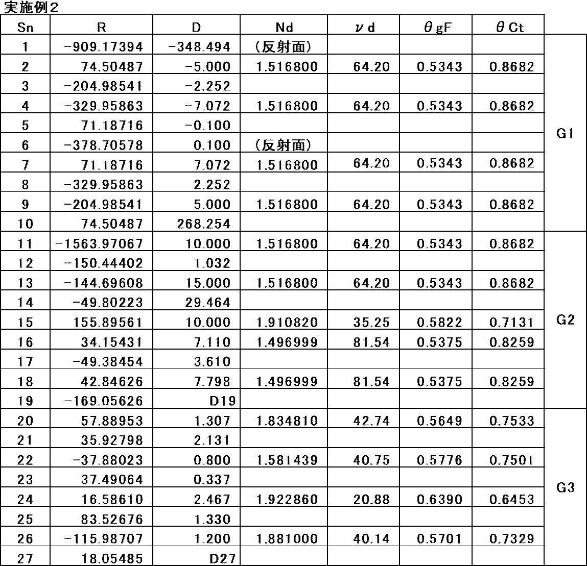
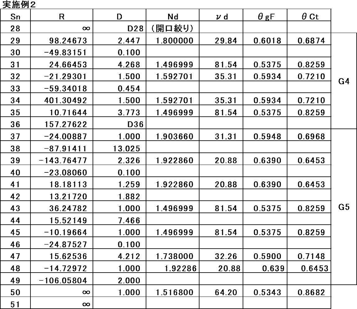
- the basic lens data is shown in Tables 3A and 3B, the specifications and variable surface spacing are shown in Table 4, and each aberration diagram is shown in FIG.
- FIG. 7 shows a cross-sectional view and an optical path of the variable magnification optical system of Example 3.
- the variable magnification optical system of Example 3 is the same as the outline of the variable magnification optical system of Example 1 except that the fourth group G4 is composed of lenses L41 to L45 and the fifth group G5 is composed of lenses L51 to L57. It has a similar configuration.
- the basic lens data is shown in Tables 5A and 5B, the specifications and variable surface spacing are shown in Table 6, and each aberration diagram is shown in FIG.
- FIG. 9 shows a cross-sectional view and an optical path of the variable magnification optical system of Example 4.
- the first group G1 is composed of the ring-shaped first mirror M1, the second mirror M2 and the lens L11
- the second group G2 is composed of the lenses L21 to L24. It has the same configuration as the outline of the variable magnification optical system of Example 1.
- the basic lens data is shown in Tables 7A and 7B, the specifications and variable surface spacing are shown in Table 8, and each aberration diagram is shown in FIG.
- FIG. 11 shows a cross-sectional view and an optical path of the variable magnification optical system of Example 5.
- the first group G1 is composed of a ring-shaped first mirror M1 and the second mirror M2, the second group G2 is composed of lenses L21 to L24, and the third group G3. It has the same configuration as the outline of the variable magnification optical system of the first embodiment except that the lens is composed of lenses L31 to L33.
- the variable magnification optical system of Example 5 has an aspherical surface.
- the basic lens data is shown in Tables 9A and 9B, the specifications and variable surface spacing are shown in Table 10, the aspherical coefficient is shown in Table 11, and each aberration diagram is shown in FIG.
- the surface numbers of the aspherical surface are marked with *, and the numerical value of the radius of curvature of the paraxial axis is described in the column of the radius of curvature of the aspherical surface.
- the Sn column shows the surface number of the aspherical surface
- the numerical value “E ⁇ n” (n: integer) of the aspherical coefficient in Table 11 means “ ⁇ 10 ⁇ n ”.
- KA and Am are aspherical coefficients in the aspherical expression represented by the following equation.
- Zd C ⁇ h 2 / ⁇ 1 + (1- (1 + K) ⁇ C 2 ⁇ h 2 ) 1/2 ⁇ + ⁇ Am ⁇ h m
- Zd Aspherical depth (length of a perpendicular line drawn from a point on the aspherical surface at height h to a plane perpendicular to the optical axis where the aspherical vertices touch)
- h Height (distance from the optical axis to the lens surface)
- C The reciprocal of the paraxial radius of curvature K
- Am the aspherical coefficient
- the aspherical ⁇ means the sum with respect to m.
- FIG. 13 shows a cross-sectional view and an optical path of the variable magnification optical system of Example 6.
- the variable magnification optical system of Example 6 has the same configuration as the outline of the variable magnification optical system of Example 1 except that the fifth group G5 is composed of lenses L51 to L57.
- the basic lens data is shown in Tables 12A and 12B, the specifications and variable surface spacing are shown in Table 13, and each aberration diagram is shown in FIG.
- FIG. 15 shows a cross-sectional view and an optical path of the variable magnification optical system of Example 7.
- the variable magnification optical system of Example 7 has the same configuration as the outline of the variable magnification optical system of Example 1 except that the fifth group G5 is composed of lenses L51 to L57.
- the basic lens data is shown in Tables 14A and 14B, the specifications and variable surface spacing are shown in Table 15, and each aberration diagram is shown in FIG.
- Table 16 shows the corresponding values of the conditional expressions (1) to (11) of the variable magnification optical system of Examples 1 to 7. Corresponding values other than the partial dispersion ratio in Table 16 are values based on the d-line.
- variable magnification optical systems of Examples 1 to 7 are reflection and refraction optical systems, and the focal length at the telephoto end exceeds 1000 mm (millimeters), but the diameter exceeds 100 mm (millimeters). There is only one large-diameter optical element, and the weight is reduced. Further, the variable magnification optical systems of Examples 1 to 7 have a magnification ratio of 3.9 times or more, have a fixed aperture stop St, and can be miniaturized while ensuring the long focal length as described above. As a result, various aberrations are satisfactorily corrected in a wide range from the visible light region to the near infrared light region, and high optical performance is realized.
- FIG. 17 shows a schematic configuration diagram of an image pickup apparatus 10 using the variable magnification optical system 1 according to the embodiment of the present disclosure as an example of the image pickup apparatus of the embodiment of the present disclosure.
- the image pickup device 10 include a surveillance camera, a video camera, an electronic still camera, and the like.
- the image pickup device 10 outputs signals from the variable magnification optical system 1, the filter 4 arranged on the image side of the variable magnification optical system 1, the image pickup element 5 arranged on the image side of the filter 4, and the image pickup element 5. It includes a signal processing unit 6 for arithmetic processing and a scaling control unit 7 for controlling the scaling of the scaling optical system 1.
- the image sensor 5 converts the optical image formed by the variable magnification optical system 1 into an electric signal.
- the image sensor 5 for example, a CCD (Charge Coupled Device) or a CMOS (Complementary Metal Oxide Semiconductor) or the like can be used.
- the image pickup device 5 is arranged so that its image pickup surface coincides with the image plane of the variable magnification optical system 1.
- the image sensor 10 may be configured to include a plurality of image sensors.
- the techniques of the present disclosure have been described above with reference to embodiments and examples, the techniques of the present disclosure are not limited to the above embodiments and examples, and various modifications are possible.
- the radius of curvature, the interplanar spacing, the refractive index, the Abbe number, the aspherical coefficient, and the like of each optical element are not limited to the values shown in the above numerical examples, and may take other values.
Landscapes
- Physics & Mathematics (AREA)
- General Physics & Mathematics (AREA)
- Optics & Photonics (AREA)
- Spectroscopy & Molecular Physics (AREA)
- Nonlinear Science (AREA)
- Lenses (AREA)
Abstract
変倍光学系は、光路に沿って物体側から順に、正のパワーを有する第1群と、正のパワーを有する第2群と、負のパワーを有する第3群と、絞りと、正のパワーを有する第4群と、正のパワーを有する第5群とを備える。第1群は2つのミラーを備える。第1群と第2群との間の光路に中間像が形成される。第2群と第3群と第4群とは屈折光学系である。変倍の際に、第1群の2つのミラーと、第2群と、絞りと、第5群とは不動であり、第3群は像側へ移動し、第4群は物体側へ移動する。
Description
本開示の技術は、変倍光学系、および撮像装置に関する。
反射屈折型の変倍光学系として、特開平11-202208号公報に記載のものが知られている。
近年、より良好な光学性能を有し、より装置の小型化が可能な、反射屈折型の変倍光学系が求められている。
上記事情に鑑み、本開示の技術は、より良好な光学性能を有し、より装置の小型化が可能な、反射屈折型の変倍光学系、およびこの変倍光学系を備えた撮像装置を提供することを目的とする。
本開示の技術の一態様に係る変倍光学系は、光路に沿って物体側から像側へ順に、正のパワーを有する第1群と、正のパワーを有する第2群と、負のパワーを有する第3群と、正のパワーを有する第4群と、正のパワーを有する第5群とからなる5つの群のみをパワーを有する群として備え、第1群は、光路上で最も物体側に位置するパワーを有する光学素子であり、かつ凹面形状の反射面を物体側に向けた第1ミラーと、第1ミラーから物体側へ向かう光を像側へ反射する、凸面形状の反射面を像側に向けた第2ミラーとを含み、第1群と第2群との間の光路に中間像が形成され、第2群と第3群と第4群とは屈折光学系であり、第3群と第4群との間に絞りが配置され、広角端から望遠端への変倍の際に、第1ミラーと、第2ミラーと、第2群と、絞りと、第5群とは像面に対して固定されており、第3群は像側へ移動し、第4群は物体側へ移動する。
上記態様の変倍光学系においては、変倍の際に第1群は像面に対して固定されており、望遠端での変倍光学系の焦点距離をfT、第1群の焦点距離をf1とした場合、下記条件式(1)を満足することが好ましく、下記条件式(1-1)を満足することがより好ましい。
0.5<|fT/f1|<4 (1)
1<|fT/f1|<2.5 (1-1)
0.5<|fT/f1|<4 (1)
1<|fT/f1|<2.5 (1-1)
上記態様の変倍光学系においては、変倍の際に第1群は像面に対して固定されており、無限遠物体に合焦した状態における第2群の横倍率をβ2とした場合、下記条件式(2)を満足することが好ましく、下記条件式(2-1)を満足することがより好ましい。
-2<β2<-0.5 (2)
-1.5<β2<-1 (2-1)
-2<β2<-0.5 (2)
-1.5<β2<-1 (2-1)
上記態様の変倍光学系においては、第3群の焦点距離をf3、第4群の焦点距離をf4とした場合、下記条件式(3)を満足することが好ましく、下記条件式(3-1)を満足することがより好ましい。
-2<f3/f4<-0.1 (3)
-1<f3/f4<-0.5 (3-1)
-2<f3/f4<-0.1 (3)
-1<f3/f4<-0.5 (3-1)
上記態様の変倍光学系においては、第4群は、最も物体側に配置された両凸レンズと、この両凸レンズより像側に配置されて正レンズと負レンズとの2枚のレンズが接合されて構成された接合レンズとを含むことが好ましい。
上記態様の変倍光学系においては、無限遠物体に合焦した状態において、望遠端での第3群の横倍率をβ3T、広角端での第3群の横倍率をβ3Wとした場合、下記条件式(4)を満足することが好ましく、下記条件式(4-1)を満足することがより好ましい。
1<β3T/β3W<5 (4)
1.2<β3T/β3W<3.5 (4-1)
1<β3T/β3W<5 (4)
1.2<β3T/β3W<3.5 (4-1)
上記態様の変倍光学系においては、無限遠物体に合焦した状態において、望遠端での第4群の横倍率をβ4T、広角端での第4群の横倍率をβ4Wとした場合、下記条件式(5)を満足することが好ましく、下記条件式(5-1)を満足することがより好ましい。
1<β4T/β4W<5 (5)
1.2<β4T/β4W<3 (5-1)
1<β4T/β4W<5 (5)
1.2<β4T/β4W<3 (5-1)
上記態様の変倍光学系においては、無限遠物体に合焦した状態において、望遠端での第3群の横倍率をβ3T、広角端での第3群の横倍率をβ3W、望遠端での第4群の横倍率をβ4T、広角端での第4群の横倍率をβ4Wとした場合、下記条件式(6)を満足することが好ましい。
0.25<(β3T/β3W)/(β4T/β4W)<2 (6)
0.25<(β3T/β3W)/(β4T/β4W)<2 (6)
上記態様の変倍光学系においては、無限遠物体に合焦した状態における広角端での第5群の横倍率をβ5Wとした場合、下記条件式(7)を満足することが好ましい。
1<β5W<3 (7)
1<β5W<3 (7)
上記態様の変倍光学系においては、第1ミラーの反射面および第2ミラーの反射面は球面形状であり、第1群は第2ミラーと中間像との間の光路に少なくとも1枚の球面レンズを含むことが好ましい。
上記態様の変倍光学系においては、第2群の全ての正レンズのg線とF線間の部分分散比の平均をθgF2P、第2群の全ての負レンズのg線とF線間の部分分散比の平均をθgF2Nとした場合、下記条件式(8)を満足することが好ましい。
-0.15<θgF2P-θgF2N<-0.005 (8)
-0.15<θgF2P-θgF2N<-0.005 (8)
上記態様の変倍光学系においては、第2群の全ての正レンズのC線とt線間の部分分散比の平均をθCt2P、第2群の全ての負レンズのC線とt線間の部分分散比の平均をθCt2Nとした場合、下記条件式(9)を満足することが好ましい。
0.01<θCt2P-θCt2N<0.3 (9)
0.01<θCt2P-θCt2N<0.3 (9)
上記態様の変倍光学系においては、第4群の全ての正レンズのg線とF線間の部分分散比の平均をθgF4P、第4群の全ての負レンズのg線とF線間の部分分散比の平均をθgF4Nとした場合、下記条件式(10)を満足することが好ましい。
-0.15<θgF4P-θgF4N<-0.005 (10)
-0.15<θgF4P-θgF4N<-0.005 (10)
上記態様の変倍光学系においては、第4群の全ての正レンズのC線とt線間の部分分散比の平均をθCt4P、第4群の全ての負レンズのC線とt線間の部分分散比の平均をθCt4Nとした場合、下記条件式(11)を満足することが好ましい。
0.01<θCt4P-θCt4N<0.3 (11)
0.01<θCt4P-θCt4N<0.3 (11)
本開示の技術の別の態様に係る撮像装置は、上記態様の変倍光学系を備えている。
なお、本明細書の「~からなり」、「~からなる」は、挙げられた構成要素以外に、実質的にパワーを有さないレンズ、並びに、絞り、フィルタ、およびカバーガラス等のレンズ以外の光学要素、並びに、レンズフランジ、レンズバレル、撮像素子、および手振れ補正機構等の機構部分、等が含まれていてもよいことを意図する。
なお、本明細書において、「正のパワーを有する~群」は、群全体として正のパワーを有することを意味する。同様に「負のパワーを有する~群」は、群全体として負のパワーを有することを意味する。「正のパワーを有するレンズ」、「正のレンズ」、および「正レンズ」は同義である。「負のパワーを有するレンズ」、「負のレンズ」、および「負レンズ」は同義である。「第2群」、「第3群」、「第4群」、および「第5群」は、複数のレンズからなる構成に限らず、1枚のみのレンズからなる構成としてもよい。
複合非球面レンズ(つまり、球面レンズと、その球面レンズ上に形成された非球面形状の膜とが一体的に構成されて、全体として1つの非球面レンズとして機能するレンズ)は、接合レンズとは見なさず、1枚のレンズとして扱う。非球面を含む光学素子に関するパワーの符号、および面形状は、近軸領域で考えることにする。レンズに関して用いている「パワー」は屈折力と同義である。「パワーを有する」とは、焦点距離の逆数が0でないことを意味する。本明細書における「屈折光学系」は、パワーを有する反射型の光学素子を含まない系である。
条件式で用いている「焦点距離」は、近軸焦点距離である。部分分散比に関する条件式以外の条件式の値は、無限遠物体に合焦した状態においてd線を基準とした場合の値である。本明細書に記載の「d線」、「C線」、「F線」、「g線」、および「t線」は輝線である。本明細書においては、d線の波長は587.56nm(ナノメートル)、C線の波長は656.27nm(ナノメートル)、F線の波長は486.13nm(ナノメートル)、g線の波長は435.83nm(ナノメートル)、t線の波長は1013.98nm(ナノメートル)として扱う。あるレンズのg線とF線間の部分分散比θgFとは、g線、F線、およびC線に対するそのレンズの屈折率をそれぞれNg、NF、およびNCとした場合、θgF=(Ng-NF)/(NF-NC)で定義される。あるレンズのC線とt線間の部分分散比θCtとは、t線、F線、およびC線に対するそのレンズの屈折率をそれぞれNt、NF、およびNCとした場合、θCt=(NC-Nt)/(NF-NC)で定義される。本明細書における「近赤外光」は、波長700nm(ナノメートル)~1000nm(ナノメートル)の帯域の光とする。
本開示の技術によれば、より良好な光学性能を有し、より装置の小型化が可能な、反射屈折型の変倍光学系、およびこの変倍光学系を備えた撮像装置を提供することができる。
以下、本開示の技術に係る実施形態の一例について図面を参照して説明する。図1に、本開示の一実施形態に係る変倍光学系の広角端における構成および光路の断面図を示す。図1では左側が物体側、右側が像側である。図1に示す例は後述の実施例1の変倍光学系に対応している。この変倍光学系は例えば監視カメラ等に適用可能である。
本実施形態の変倍光学系は、光路に沿って物体側から像側へ順に、正のパワーを有する第1群G1と、正のパワーを有する第2群G2と、負のパワーを有する第3群G3と、正のパワーを有する第4群G4と、正のパワーを有する第5群G5とからなる5つの群のみをパワーを有する群として備える。第3群G3と第4群G4との間に開口絞りStが配置されている。なお、図1の開口絞りStは形状および大きさを示しているのではなく、光軸方向の位置を示しており、開口絞りStに関するこの図示方法は他の図についても同様である。
図1では、変倍光学系が撮像装置に適用されることを想定して、変倍光学系と像面Simとの間に平行平板状の光学部材PPが配置された例を示している。光学部材PPは、各種フィルタおよびカバーガラス等を想定した部材である。各種フィルタとは例えば、ローパスフィルタ、赤外線カットフィルタ、および特定の波長域をカットするフィルタ等である。光学部材PPはパワーを有しない部材であり、光学部材PPを省略した構成も可能である。
一例として図1の例の各群は以下の光学素子から構成されている。すなわち、第1群G1は、光路に沿って物体側から像側へ順に、第1ミラーM1と、レンズL11と、レンズL12と、第2ミラーM2とからなる。第2群G2は、物体側から像側へ順に、レンズL21~L25の5枚のレンズからなる。第3群G3は、物体側から像側へ順に、レンズL31~L34の4枚のレンズからなる。第4群G4は、物体側から像側へ順に、レンズL41~L44の4枚のレンズからなる。第5群G5は、物体側から像側へ順に、レンズL51~L55の5枚のレンズからなる。図1の例では上記の全ての光学素子が共通の光軸Zを有する。
図1の例の変倍光学系はズーム光学系である。広角端から望遠端への変倍の際に、第1ミラーM1と、第2ミラーM2と、第2群G2と、開口絞りStと、第5群G5とは像面Simに対して固定されており、第3群G3は物体側から像側へ移動し、第4群G4は像側から物体側へ移動する。図1では、第3群G3および第4群G4の下にそれぞれ、広角端から望遠端へ変倍する際の各群の移動軌跡を模式的に矢印で示している。
図1の例では、第1ミラーM1は中心部に開口部を有するリング形状である。図1の例では、物体から変倍光学系に入射した光は、まず第1ミラーM1で物体側へ反射され、レンズL11とレンズL12をこの順に経由した後、第2ミラーM2で像側へ反射され、レンズL12とレンズL11をこの順に経由した後、第2群G2、第3群G3、第4群G4、および第5群G5を経由して像面Simに到達する。
無限遠物体に合焦している状態において、第1群G1と第2群G2との間の光路には中間像Imが形成される。図1では中間像Imの光軸付近を含む一部のみを簡略的に点線で表しており、その形状は必ずしも正確ではない。中間像Imは、第2群G2、第3群G3、第4群G4、および第5群G5を介して像面Sim上に再結像される。すなわち、第2群G2から第5群G5まではリレー光学系として機能する。変倍光学系を再結像光学系とすることによって、変倍の際に移動する群のレンズ径を小さくすることができるので、装置の小型化、および変倍動作の高速化に有利となる。
第1群G1は、全体として正のパワーを有する。第1群G1は、第1ミラーM1および第2ミラーM2を備える。第1ミラーM1は、凹面形状の反射面を物体側に向けており、物体から入射された光を物体側へ反射する。第2ミラーM2は、凸面形状の反射面を像側に向けており、第1ミラーM1から物体側へ向かう光を像側へ反射する。すなわち、第1ミラーM1と第2ミラーM2とは各反射面が対向するように配置されている。ミラーは色収差に関与しないため、上記2枚のミラーでは長焦点レンズ系で課題となる色収差が発生することはない。第1群G1に上記ミラーを用いることによって、色収差をほぼ発生させずに超望遠光学系を得ることが容易となる。また、各反射面が対向配置された2枚のミラーを用いることによって光路を折り返すことができるため光学全長を短縮化することができる。
第1ミラーM1は、変倍光学系に含まれるパワーを有する光学素子のうち、光路上で最も物体側に位置する光学素子である。仮に、第1ミラーM1よりも物体側の光路に屈折光学系を配置すると、その屈折光学系の口径は大きなものとなるため、高価となってしまう。また、第1ミラーM1よりも物体側の光路に屈折光学系を配置すると、変倍光学系の重心が先端部の方に偏って位置し重量バランスが悪くなるため、好ましくない。さらに、反射型の光学素子は、光線が透過しないため、透過型の光学素子に比べて材料の選択の自由度が高いという長所もある。
第1ミラーM1の反射面および第2ミラーM2の反射面は球面形状であることが好ましい。このようにした場合は、非球面形状にした場合に比べ安価に製造可能である。第1ミラーM1の反射面および第2ミラーM2の反射面を球面形状にした場合は、第1群G1は第2ミラーM2と中間像Imとの間の光路に少なくとも1枚の球面レンズを含むように構成してもよい。上記位置に少なくとも1枚の球面レンズを配置することによって、2枚の球面ミラーで発生する球面収差を補正することができるので、加工および測定が難しい非球面ミラーを用いることなく高い光学性能を得ることが容易となる。
図1の例では第2ミラーM2と中間像Imとの間の光路に、負のレンズL11および正のレンズL12が2枚の球面レンズとして配置されている。これら2枚の球面レンズは第1ミラーM1と第2ミラーM2との間の光路にも位置している。従って、第1ミラーM1で反射された光が第2ミラーM2へ向かう際と、第2ミラーM2で反射された光が中間像Imへ向かう際との2回、光線は上記2枚の球面レンズを通過する。このように光線が往復する光路中に球面レンズを配置することによって、レンズおよびミラー等の光学素子の数を少なくしても球面収差を良好に補正することが容易となり、さらには光学素子の数を少なくして、かつ、第1ミラーM1および第2ミラーM2ともに非球面を用いない場合でも、球面収差を良好に補正することが容易となる。
第2ミラーM2と中間像Imとの間の光路に配置されるレンズの枚数を1枚又は2枚にした場合は、3枚以上にした場合に比べて、変倍光学系の物体側の部分への荷重を小さく抑えることができ、変倍光学系を設置するための架台に要求される強度を低くすることができる。第2ミラーM2と中間像Imとの間の光路に配置されるレンズの枚数を1枚にした場合は、2枚以上にした場合よりも使用する光学素子の数が少なくなるためコストおよび製造性の点で有利となる。
第1群G1は変倍の際に像面Simに対して固定されていることが好ましい。すなわち、ミラー以外の素子も含め、第1群G1を構成する全ての光学素子は変倍の際に像面Simに対して固定されていることが好ましく、このようにした場合は、装置の構成をより簡素化できる。
第2群G2は、屈折光学系であり、全体として正のパワーを有する。中間像Imより像側で光束が発散に転じる位置に正のパワーを有する第2群G2を配置することによって、光束の発散を抑えることができ、これによって第2群G2より像側のレンズを小型化することに有利となる。
第3群G3は、屈折光学系であり、全体として負のパワーを有する。第4群G4は、屈折光学系であり、全体として正のパワーを有する。すなわち、第2群G2、第3群G3、第4群G4はそれぞれ正、負、正のパワーを有し、隣り合う群のパワーが互いに異符号となるように配置されている。これによって、各群のパワーを強めることが可能となり、変倍の際の各群の移動量を短縮化できるので光学系の小型化が可能となる。
第4群G4は、最も物体側に配置された両凸レンズと、両凸レンズより像側に配置されて正レンズと負レンズとの2枚のレンズが接合されて構成された接合レンズとを含むことが好ましい。この接合レンズは、正レンズと負レンズとが物体側から順に接合されていてもよく、負レンズと正レンズとが物体側から順に接合されていてもよい。第3群G3で発散作用を受けて第3群G3から射出した光束に第4群G4の両凸レンズが収束作用を施すことができるため、第4群G4のレンズ外径の大径化を抑制することが容易となる。また、両凸レンズの像側に上記接合レンズを配置することによって、両凸レンズで発生した軸上色収差を補正することができる。
図1の例の第5群G5は屈折光学系である。第5群G5は全体として正のパワーを有する。像面Simに最も近い位置に正のパワーを有する第5群G5を配置することによって、像面湾曲の補正が可能となり、結像領域の中心から周辺まで良好な光学性能を得ることが容易となる。
開口絞りStは第3群G3と第4群G4との間に配置されており、これによって開口絞りStの小型化を図ることができる。種々の撮影条件に対応するためには開口絞りStの開口径は可変であることが好ましく、特に、日中から夜間まで撮影が行われる監視カメラ用途では開口径が可変であることが好ましい。一方、開口絞りStが大型になれば開口径を変化させる絞り機構も大型になるため、装置の小型化のためには開口絞りStも小型であることが好ましい。
開口絞りStを配置する位置としては、開口絞りStを絞った際に周辺光量比の低下が生じにくい位置であることが好ましい。本変倍光学系のような構成では、第1ミラーM1および第2ミラーM2のどちらかの近傍に開口絞りStを配置することが考えられる。しかしながら、第1ミラーM1の近傍に開口絞りStを置いた場合は、絞り機構が非常に大型化してしまう。また、第2ミラーM2の近傍に開口絞りStを置いた場合は、入射光束の一部が絞り機構により遮光されてしまうため、光量損失が大きくなってしまい、低照度でも使用可能な監視カメラ用途の光学系としての価値が低下してしまう。
中間像Imより像側の光路に開口絞りStを配置する場合は、開口絞りStを絞った際に結像領域の一部が遮光されないような位置に配置することが好ましい。このため、開口絞りStの光軸方向の位置としては、軸上光束の上光線と軸外光束の上光線とが交わる点(以下、点P1という)から、軸上光束の下光線と軸外光束の下光線とが交わる点(以下、点P2という)までの範囲内であることが好ましい。
比較例として、図2に第2群G2と第3群G3との間に開口絞りStを配置した場合の例を示す。本変倍光学系では光軸近傍の光束は結像に使用されないため、図2では軸上光束Baおよび軸外光束Bxのうち、結像に使用されない部分は白抜きにし、結像に使用される部分は斜線を付している。第2群G2と第3群G3との間に開口絞りStを配置する場合は、図2に示すように点P1から点P2までの範囲は第3群近傍となるため、第3群G3と第4群G4との間に開口絞りStを配置する場合に比べ、広角端で第2群G2と開口絞りStとの間隔が広くなってしまい、従って、第2群G2と第3群G3との間隔も広くなってしまい、光学全長の増大を招いてしまう。
図3に第3群G3と第4群G4との間に開口絞りStを配置した場合の例を示す。この場合、第2群G2から射出して第3群G3に入射した軸外光束Bxは負のパワーの第3群G3により発散作用を受けるため、第3群G3から射出した軸外光束の光軸Zに対する傾角は第2群G2から射出した軸外光束の光軸Zに対する傾角よりも、小さくなる。そのため、第2群G2と第3群G3との間に開口絞りStを配置した場合に比べ、点P1および点P2がより像側に位置する。図3に示すように第3群G3と第4群G4との間に開口絞りStを配置した場合は、図2の例とは異なり第3群G3の物体側に開口絞りStが無いため、広角端での第2群G2と第3群G3との間隔を短くすることができると同時に、変倍に求められる第3群G3の移動量を確保することができる。
開口絞りStを第4群G4と第5群G5との間に配置した場合は、この位置以外に配置した場合に比べ、軸外光束の下側の光線をより多く通すことが好ましいため、第3群G3のレンズの外径が大きくなってしまう。
開口絞りStは変倍の際に像面Simに対して固定されている。仮に、変倍の際に開口絞りStが移動するように構成した場合は、開口絞りStを駆動するための駆動部品へ電力を供給することになり、そのための導線が断線するリスクが生じる。これに対して、変倍の際に開口絞りStが固定されている構成ではそのようなリスクは生じないため監視用途として重要な耐久性をより高く保持することができる。
次に、本実施形態の変倍光学系の条件式に関する構成について説明する。変倍光学系は、変倍の際に第1群G1が像面Simに対して固定されており、望遠端での変倍光学系の焦点距離をfT、第1群G1の焦点距離をf1とした場合、下記条件式(1)を満足することが好ましい。条件式(1)の下限以下とならないようにすることによって、第1群G1のパワーが弱まり過ぎず、光学全長の長大化を抑制することができる。条件式(1)の上限以上とならないようにすることによって、第2ミラーM2と中間像Imとの間隔が短くなり過ぎないため、中間像Imがより像側に位置することになり、これに伴い、第2群G2もより像側に位置することになり、第2群G2と第2ミラーM2との距離を長くとることができる。その結果、第2群G2によって遮光される光軸近傍の光束の量をより少なくできるので、光量の確保に有利となる。仮に、第2群G2と第2ミラーM2との距離がより短くなると、第2群G2によって遮光される光軸近傍の光束の量が増大してしまう。さらに下記条件式(1-1)を満足する構成とすれば、より良好な特性とすることができる。
0.5<|fT/f1|<4 (1)
1<|fT/f1|<2.5 (1-1)
0.5<|fT/f1|<4 (1)
1<|fT/f1|<2.5 (1-1)
変倍の際に第1群G1は像面Simに対して固定されており、無限遠物体に合焦した状態における第2群G2の横倍率をβ2とした場合、下記条件式(2)を満足することが好ましい。条件式(2)を満足することによって、球面収差の発生を抑制することに有利となる。より詳しくは、条件式(2)の下限以下とならないようにすることによって、第2群G2からの射出光束を適切に集光させることができるため、第3群G3からの射出光束の発散角度が大きくなり過ぎないようにすることができ、これによって球面収差の発生の抑制に有利となる。また、条件式(2)の上限以上とならないようにすることによって、第2群G2からの射出光束の射出角度が大きくなり過ぎないため球面収差の発生の抑制に有利となる。さらに下記条件式(2-1)を満足する構成とすれば、より良好な特性とすることができる。
-2<β2<-0.5 (2)
-1.5<β2<-1 (2-1)
-2<β2<-0.5 (2)
-1.5<β2<-1 (2-1)
第3群G3の焦点距離をf3、第4群G4の焦点距離をf4とした場合、下記条件式(3)を満足することが好ましい。条件式(3)の下限以下とならないようにすることによって、第3群G3の負のパワーが弱くなり過ぎないため、変倍の際の第3群G3の移動量を短縮化でき、これにより光学全長の長大化を抑制することができる。また、第3群G3の移動量の短縮化によって、広角端における第3群G3と開口絞りStとの距離の長大化の抑制に有利となるので、第3群G3のレンズ外径の大径化の抑制に有利となる。条件式(3)の上限以上とならないようにすることによって、第4群G4の正のパワーが弱くなり過ぎないため、変倍の際の第4群G4の移動量の短縮化に有利となり、これにより光学全長の長大化を抑制することができる。また、第4群G4の移動量の短縮化によって、広角端における第4群G4と開口絞りStとの距離の長大化の抑制に有利となるので、第4群G4のレンズ外径の大径化の抑制に有利となる。さらに下記条件式(3-1)を満足する構成とすれば、より良好な特性とすることができる。
-2<f3/f4<-0.1 (3)
-1<f3/f4<-0.5 (3-1)
-2<f3/f4<-0.1 (3)
-1<f3/f4<-0.5 (3-1)
無限遠物体に合焦した状態において、望遠端での第3群G3の横倍率をβ3T、広角端での第3群G3の横倍率をβ3Wとした場合、下記条件式(4)を満足することが好ましい。条件式(4)の下限以下とならないようにすることによって、変倍の際の第3群G3の移動量を短縮化できるので光学全長の長大化を抑えることができる。条件式(4)の上限以上とならないようにすることによって、第3群G3のパワーが強くなり過ぎないため、変倍に伴う収差変動を抑制することができる。さらに下記条件式(4-1)を満足する構成とすれば、より良好な特性とすることができる。
1<β3T/β3W<5 (4)
1.2<β3T/β3W<3.5 (4-1)
1<β3T/β3W<5 (4)
1.2<β3T/β3W<3.5 (4-1)
無限遠物体に合焦した状態において、望遠端での第4群G4の横倍率をβ4T、広角端での第4群G4の横倍率をβ4Wとした場合、下記条件式(5)を満足することが好ましい。条件式(5)の下限以下とならないようにすることによって、変倍の際の第4群G4の移動量を短縮化できるので光学全長の長大化を抑えることができる。条件式(5)の上限以上とならないようにすることによって、第4群G4のパワーが強くなり過ぎないため、変倍に伴う収差変動を抑制することができる。さらに下記条件式(5-1)を満足する構成とすれば、より良好な特性とすることができる。
1<β4T/β4W<5 (5)
1.2<β4T/β4W<3 (5-1)
1<β4T/β4W<5 (5)
1.2<β4T/β4W<3 (5-1)
無限遠物体に合焦した状態において、望遠端での第3群G3の横倍率をβ3T、広角端での第3群G3の横倍率をβ3W、望遠端での第4群G4の横倍率をβ4T、広角端での第4群G4の横倍率をβ4Wとした場合、下記条件式(6)を満足することが好ましい。条件式(6)を満足することによって、第3群G3および第4群G4をバランス良く変倍に寄与させることができる。条件式(6)を満足することによって、第3群G3および第4群G4のいずれか一方のみパワーが強くなり過ぎることが無いため、変倍に伴う収差変動を極力低減することが可能となる。さらに下記条件式(6-1)を満足する構成とすれば、より良好な特性とすることができる。
0.25<(β3T/β3W)/(β4T/β4W)<2 (6)
0.5<(β3T/β3W)/(β4T/β4W)<1.5 (6-1)
0.25<(β3T/β3W)/(β4T/β4W)<2 (6)
0.5<(β3T/β3W)/(β4T/β4W)<1.5 (6-1)
無限遠物体に合焦した状態における広角端での第5群G5の横倍率をβ5Wとした場合、下記条件式(7)を満足することが好ましい。条件式(7)の下限以下とならないようにすることによって、第1群G1から第4群G4までの合成焦点距離を短くできるため、光学全長を短くすることができる。条件式(7)の上限以上とならないようにすることによって、像面湾曲の増大を抑え、結像領域周辺部の画像の劣化を抑制することができる。さらに下記条件式(7-1)を満足する構成とすれば、より良好な特性とすることができる。
1<β5W<3 (7)
1.2<β5W<2.5 (7-1)
1<β5W<3 (7)
1.2<β5W<2.5 (7-1)
第2群G2の全ての正レンズのg線とF線間の部分分散比の平均をθgF2P、第2群G2の全ての負レンズのg線とF線間の部分分散比の平均をθgF2Nとした場合、下記条件式(8)を満足することが好ましい。条件式(8)を満足することによって、可視光域における二次の軸上色収差の発生を抑えることができる。さらに下記条件式(8-1)を満足する構成とすれば、より良好な特性とすることができる。
-0.15<θgF2P-θgF2N<-0.005 (8)
-0.09<θgF2P-θgF2N<-0.015 (8-1)
-0.15<θgF2P-θgF2N<-0.005 (8)
-0.09<θgF2P-θgF2N<-0.015 (8-1)
第2群G2の全ての正レンズのC線とt線間の部分分散比の平均をθCt2P、第2群G2の全ての負レンズのC線とt線間の部分分散比の平均をθCt2Nとした場合、下記条件式(9)を満足することが好ましい。条件式(9)を満足することによって、赤色光から近赤外光域における二次の軸上色収差の発生を抑えることができる。さらに下記条件式(9-1)を満足する構成とすれば、より良好な特性とすることができる。
0.01<θCt2P-θCt2N<0.3 (9)
0.025<θCt2P-θCt2N<0.2 (9-1)
0.01<θCt2P-θCt2N<0.3 (9)
0.025<θCt2P-θCt2N<0.2 (9-1)
第4群G4の全ての正レンズのg線とF線間の部分分散比の平均をθgF4P、第4群G4の全ての負レンズのg線とF線間の部分分散比の平均をθgF4Nとした場合、下記条件式(10)を満足することが好ましい。条件式(10)を満足することによって、可視光域における二次の軸上色収差および二次の倍率色収差の発生を抑えることができる。さらに下記条件式(10-1)を満足する構成とすれば、より良好な特性とすることができる。
-0.15<θgF4P-θgF4N<-0.005 (10)
-0.09<θgF4P-θgF4N<-0.015 (10-1)
-0.15<θgF4P-θgF4N<-0.005 (10)
-0.09<θgF4P-θgF4N<-0.015 (10-1)
第4群G4の全ての正レンズのC線とt線間の部分分散比の平均をθCt4P、第4群G4の全ての負レンズのC線とt線間の部分分散比の平均をθCt4Nとした場合、下記条件式(11)を満足することが好ましい。条件式(11)を満足することによって、赤色光から近赤外光域における二次の軸上色収差および二次の倍率色収差の発生を抑えることができる。さらに下記条件式(11-1)を満足する構成とすれば、より良好な特性とすることができる。
0.01<θCt4P-θCt4N<0.3 (11)
0.025<θCt4P-θCt4N<0.2 (11-1)
0.01<θCt4P-θCt4N<0.3 (11)
0.025<θCt4P-θCt4N<0.2 (11-1)
上述した好ましい構成および可能な構成は、任意の組合せが可能であり、要求される仕様に応じて適宜選択的に採用されることが好ましい。また、本開示の技術の主旨を逸脱しない範囲内において種々の変形が可能である。例えば、各群を構成するレンズの枚数は、図1に示す例と異なる枚数にすることも可能である。また、変倍光学系は、バリフォーカル光学系にすることも可能である。
次に、本開示の変倍光学系の数値実施例について説明する。なお、各実施例の断面図のレンズに付された参照符号は、参照符号の桁数の増大による説明の煩雑化を避けるため、実施例ごとに独立して用いている。したがって、異なる実施例の図面において共通の参照符号が付されていても、必ずしも共通の構成ではない。
[実施例1]
実施例1の変倍光学系の断面図と光路は図1に示されており、その構成および図示方法は上述したとおりであるので、ここでは重複説明を一部省略する。実施例1の変倍光学系は、光路に沿って物体側から像側へ向かって順に、正のパワーを有する第1群G1と、正のパワーを有する第2群G2と、負のパワーを有する第3群G3と、開口絞りStと、正のパワーを有する第4群G4と、正のパワーを有する第5群G5とからなるズーム光学系である。第1群G1と第2群G2との間の光路に中間像Imが形成されている。広角端から望遠端への変倍の際に、第3群G3は像側へ移動し、第4群G4は物体側へ移動し、開口絞りStも含めその他の構成要素は像面Simに対して固定されている。第1群G1は、リング形状の第1ミラーM1と、第2ミラーM2と、レンズL11と、レンズL12とからなる。第2群G2はレンズL21~L25からなる。第3群G3はレンズL31~L34からなる。第4群G4はレンズL41~L44からなる。第5群G5はレンズL51~L55からなる。以上が実施例1の変倍光学系の概要である。
[実施例1]
実施例1の変倍光学系の断面図と光路は図1に示されており、その構成および図示方法は上述したとおりであるので、ここでは重複説明を一部省略する。実施例1の変倍光学系は、光路に沿って物体側から像側へ向かって順に、正のパワーを有する第1群G1と、正のパワーを有する第2群G2と、負のパワーを有する第3群G3と、開口絞りStと、正のパワーを有する第4群G4と、正のパワーを有する第5群G5とからなるズーム光学系である。第1群G1と第2群G2との間の光路に中間像Imが形成されている。広角端から望遠端への変倍の際に、第3群G3は像側へ移動し、第4群G4は物体側へ移動し、開口絞りStも含めその他の構成要素は像面Simに対して固定されている。第1群G1は、リング形状の第1ミラーM1と、第2ミラーM2と、レンズL11と、レンズL12とからなる。第2群G2はレンズL21~L25からなる。第3群G3はレンズL31~L34からなる。第4群G4はレンズL41~L44からなる。第5群G5はレンズL51~L55からなる。以上が実施例1の変倍光学系の概要である。
実施例1の変倍光学系について、基本レンズデータを表1Aおよび表1Bに、諸元と可変面間隔を表2に示す。ここでは、1つの表の長大化を避けるため基本レンズデータを表1Aおよび表1Bの2つの表に分けて表示している。表1Aには第1群G1、第2群G2、および第3群G3を示し、表1Bには開口絞りSt、第4群G4、第5群G5、および光学部材PPを示す。表1Aおよび表1Bでは最も右の欄を群ごとに区切り、各群の符号であるG1~G5を示す。
表1Aおよび表1Bでは光路に沿って構成要素を示している。表1Aおよび表1Bにおいて、Snの欄には光路上で最も物体側の面を第1面とし光路に沿って像側に向かうに従い1つずつ番号を増加させた場合の面番号を示し、Rの欄には各面の曲率半径を示し、Dの欄には各面と光路上でその像側に隣接する面との光軸上の面間隔を示す。Ndの欄には各構成要素のd線における屈折率を示し、νdの欄には各構成要素のd線基準のアッベ数を示し、θgFの欄には各構成要素のg線とF線間の部分分散比を示し、θCtの欄には各構成要素のC線とt線間の部分分散比を示す。
表1Aおよび表1Bでは、物体側に凸面を向けた形状の面の曲率半径の符号を正、像側に凸面を向けた形状の面の曲率半径の符号を負としている。表1Aでは反射面に相当する面のNdの欄に「(反射面)」を記入し、表1Bでは開口絞りStに相当する面のNdの欄に「(開口絞り)」を記入している。また、表1Aおよび表1Bでは変倍の際の可変面間隔については、「D」にその間隔の物体側の面番号を付してDの欄に記入している。
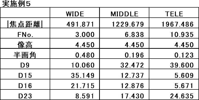
表2に、変倍光学系の焦点距離の絶対値、Fナンバー、最大像高、最大半画角をそれぞれ、「|焦点距離|」、「FNo.」、「像高」、「半画角」と表記した行に示す。表2には各可変面間隔の値も示す。表2では、広角端状態、中間焦点距離状態、望遠端状態の各値をそれぞれ「WIDE」、「MIDDLE」、「TELE」と表記した欄に示す。表1A、表1B、および表2には、無限遠物体に合焦した状態において、d線を基準とした場合のデータを示す。
各表のデータにおいて、角度の単位としては度を用い、長さの単位としてはmm(ミリメートル)を用いているが、光学系は比例拡大又は比例縮小しても使用可能なため他の適当な単位を用いることもできる。また、以下に示す各表では所定の桁でまるめた数値を記載している。

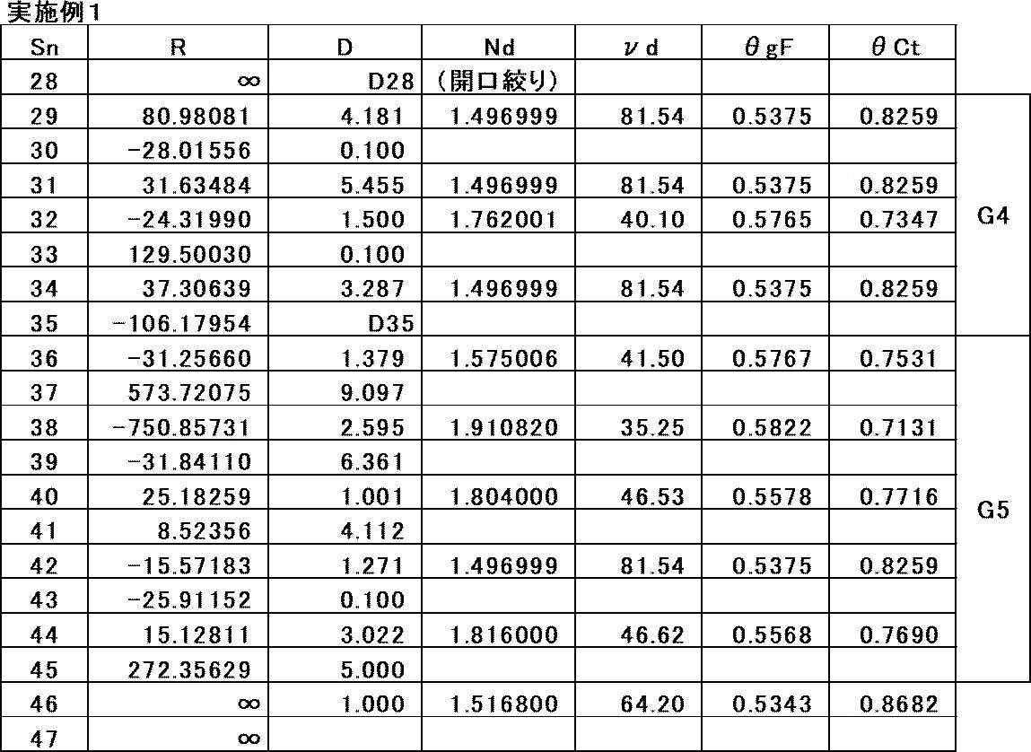
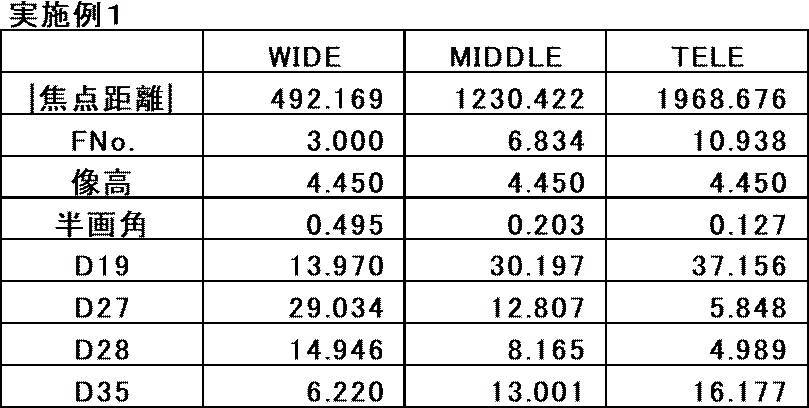
図4に、実施例1の変倍光学系の無限遠物体に合焦した状態の各収差図を示す。図4では左から順に、球面収差、非点収差、歪曲収差、および倍率色収差を示す。図4では「WIDE」と付した上段に広角端状態における収差図を示し、「MIDDLE」と付した中段に中間焦点距離状態における収差図を示し、「TELE」と付した下段に望遠端状態における収差図を示す。球面収差図では、d線、g線、F線、C線、およびt線における収差をそれぞれ実線、長破線、一点鎖線、短破線、および点線で示す。非点収差図では、サジタル方向のd線における収差を実線で示し、メリディオナル方向のd線における収差を破線で示す。歪曲収差図ではd線における収差を実線で示す。倍率色収差図では、t線、およびg線における収差をそれぞれ破線、および実線で示す。球面収差図では「FNo.=」の横にFナンバーの値を示し、その他の収差図では「IH=」の横に最大像高の値を示す。なお、第1ミラーM1はリング形状のため、図4の球面収差図の縦軸の0近傍のデータは参考データとして示す。
上記の実施例1に関する各データの記号、意味、記載方法、および図示方法は、特に断りが無い限り以下の実施例においても同様であるので、以下では重複説明を省略する。
[実施例2]
実施例2の変倍光学系の断面図と光路を図5に示す。実施例2の変倍光学系は、第4群G4がレンズL41~L45からなる点、および第5群G5がレンズL51~L57からなる点以外は、実施例1の変倍光学系の概要と同様の構成を有する。実施例2の変倍光学系について、基本レンズデータを表3Aおよび表3Bに、諸元と可変面間隔を表4に、各収差図を図6に示す。
実施例2の変倍光学系の断面図と光路を図5に示す。実施例2の変倍光学系は、第4群G4がレンズL41~L45からなる点、および第5群G5がレンズL51~L57からなる点以外は、実施例1の変倍光学系の概要と同様の構成を有する。実施例2の変倍光学系について、基本レンズデータを表3Aおよび表3Bに、諸元と可変面間隔を表4に、各収差図を図6に示す。

[実施例3]
実施例3の変倍光学系の断面図と光路を図7に示す。実施例3の変倍光学系は、第4群G4がレンズL41~L45からなる点、および第5群G5がレンズL51~L57からなる点以外は、実施例1の変倍光学系の概要と同様の構成を有する。実施例3の変倍光学系について、基本レンズデータを表5Aおよび表5Bに、諸元と可変面間隔を表6に、各収差図を図8に示す。
実施例3の変倍光学系の断面図と光路を図7に示す。実施例3の変倍光学系は、第4群G4がレンズL41~L45からなる点、および第5群G5がレンズL51~L57からなる点以外は、実施例1の変倍光学系の概要と同様の構成を有する。実施例3の変倍光学系について、基本レンズデータを表5Aおよび表5Bに、諸元と可変面間隔を表6に、各収差図を図8に示す。

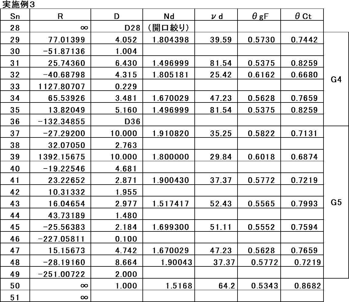
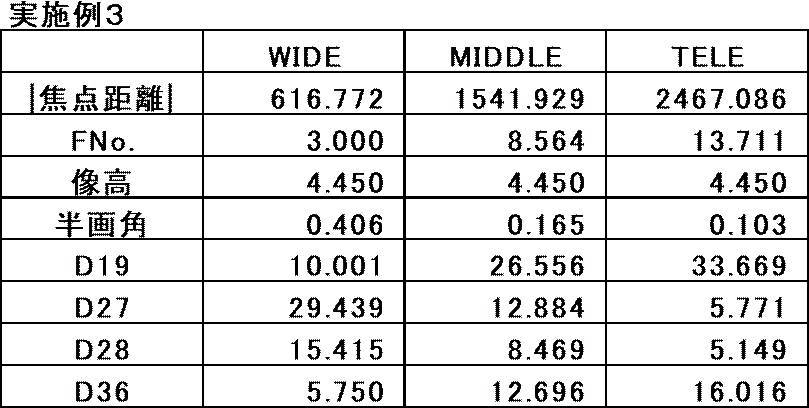
[実施例4]
実施例4の変倍光学系の断面図と光路を図9に示す。実施例4の変倍光学系は、第1群G1がリング形状の第1ミラーM1と第2ミラーM2とレンズL11とからなる点、および第2群G2がレンズL21~L24からなる点以外は実施例1の変倍光学系の概要と同様の構成を有する。実施例4の変倍光学系について、基本レンズデータを表7Aおよび表7Bに、諸元と可変面間隔を表8に、各収差図を図10に示す。
実施例4の変倍光学系の断面図と光路を図9に示す。実施例4の変倍光学系は、第1群G1がリング形状の第1ミラーM1と第2ミラーM2とレンズL11とからなる点、および第2群G2がレンズL21~L24からなる点以外は実施例1の変倍光学系の概要と同様の構成を有する。実施例4の変倍光学系について、基本レンズデータを表7Aおよび表7Bに、諸元と可変面間隔を表8に、各収差図を図10に示す。

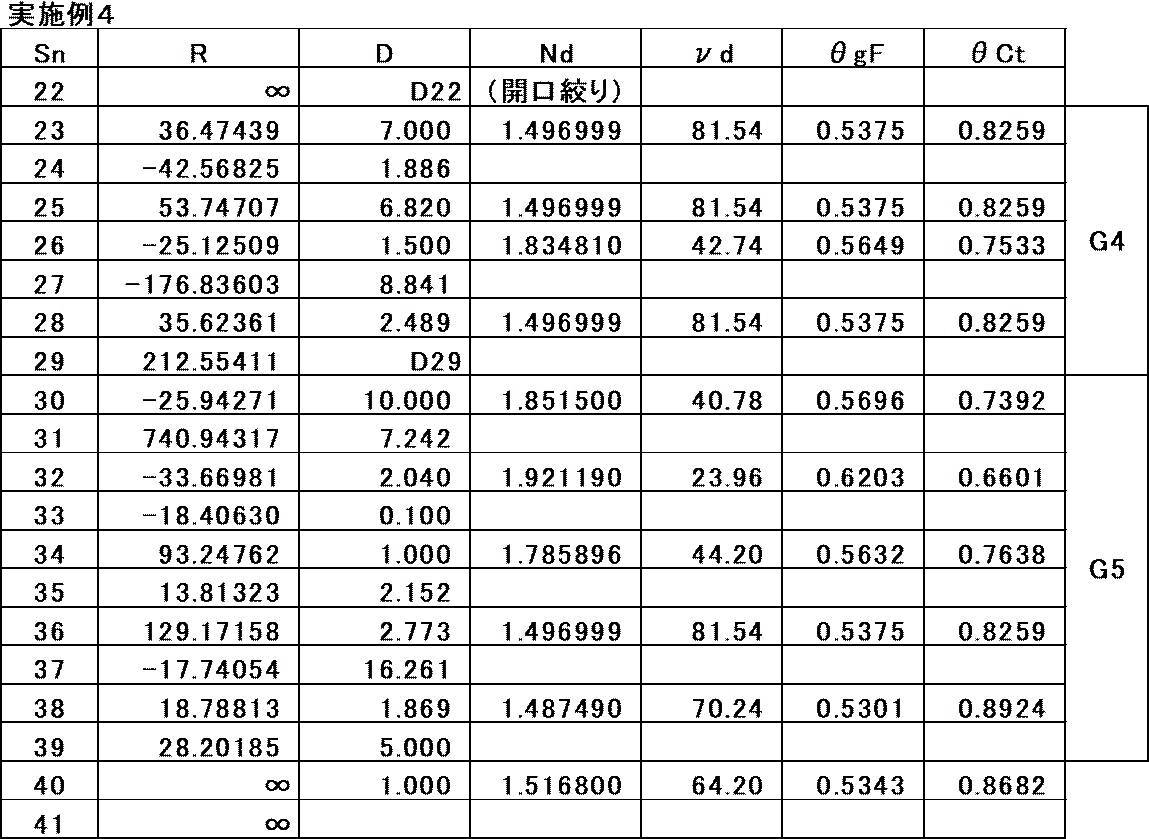

[実施例5]
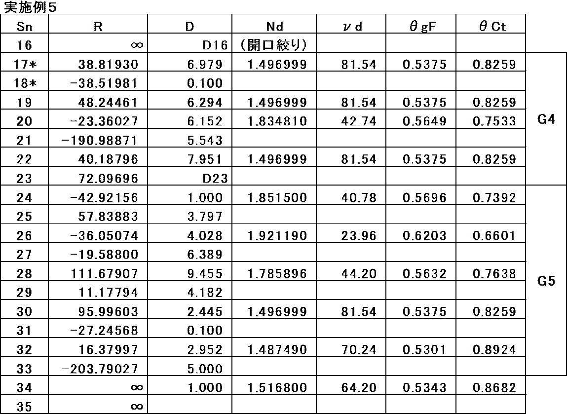
実施例5の変倍光学系の断面図と光路を図11に示す。実施例5の変倍光学系は、第1群G1がリング形状の第1ミラーM1と第2ミラーM2とからなる点、第2群G2がレンズL21~L24からなる点、および第3群G3がレンズL31~L33からなる点以外は実施例1の変倍光学系の概要と同様の構成を有する。実施例5の変倍光学系は非球面を有する。実施例5の変倍光学系について、基本レンズデータを表9Aおよび表9Bに、諸元と可変面間隔を表10に、非球面係数を表11に、各収差図を図12に示す。
実施例5の変倍光学系の断面図と光路を図11に示す。実施例5の変倍光学系は、第1群G1がリング形状の第1ミラーM1と第2ミラーM2とからなる点、第2群G2がレンズL21~L24からなる点、および第3群G3がレンズL31~L33からなる点以外は実施例1の変倍光学系の概要と同様の構成を有する。実施例5の変倍光学系は非球面を有する。実施例5の変倍光学系について、基本レンズデータを表9Aおよび表9Bに、諸元と可変面間隔を表10に、非球面係数を表11に、各収差図を図12に示す。
基本レンズデータの表では、非球面の面番号に*印を付しており、非球面の曲率半径の欄には近軸の曲率半径の数値を記載している。非球面係数の表において、Snの欄には非球面の面番号を示し、KAおよびAm(m=4、6、8、10)の欄には各非球面についての非球面係数の数値を示す。表11の非球面係数の数値の「E±n」(n:整数)は「×10±n」を意味する。KAおよびAmは下式で表される非球面式における非球面係数である。
Zd=C×h2/{1+(1-(1+K)×C2×h2)1/2}+ΣAm×hm
ただし、
Zd:非球面深さ(高さhの非球面上の点から、非球面頂点が接する光軸に垂直な平面に
下ろした垂線の長さ)
h:高さ(光軸からレンズ面までの距離)
C:近軸曲率半径の逆数
K、Am:非球面係数
であり、非球面式のΣはmに関する総和を意味する。
Zd=C×h2/{1+(1-(1+K)×C2×h2)1/2}+ΣAm×hm
ただし、
Zd:非球面深さ(高さhの非球面上の点から、非球面頂点が接する光軸に垂直な平面に
下ろした垂線の長さ)
h:高さ(光軸からレンズ面までの距離)
C:近軸曲率半径の逆数
K、Am:非球面係数
であり、非球面式のΣはmに関する総和を意味する。


[実施例6]
実施例6の変倍光学系の断面図と光路を図13に示す。実施例6の変倍光学系は、第5群G5がレンズL51~L57からなる点以外は、実施例1の変倍光学系の概要と同様の構成を有する。実施例6の変倍光学系について、基本レンズデータを表12Aおよび表12Bに、諸元と可変面間隔を表13に、各収差図を図14に示す。
実施例6の変倍光学系の断面図と光路を図13に示す。実施例6の変倍光学系は、第5群G5がレンズL51~L57からなる点以外は、実施例1の変倍光学系の概要と同様の構成を有する。実施例6の変倍光学系について、基本レンズデータを表12Aおよび表12Bに、諸元と可変面間隔を表13に、各収差図を図14に示す。


[実施例7]
実施例7の変倍光学系の断面図と光路を図15に示す。実施例7の変倍光学系は、第5群G5がレンズL51~L57からなる点以外は、実施例1の変倍光学系の概要と同様の構成を有する。実施例7の変倍光学系について、基本レンズデータを表14Aおよび表14Bに、諸元と可変面間隔を表15に、各収差図を図16に示す。
実施例7の変倍光学系の断面図と光路を図15に示す。実施例7の変倍光学系は、第5群G5がレンズL51~L57からなる点以外は、実施例1の変倍光学系の概要と同様の構成を有する。実施例7の変倍光学系について、基本レンズデータを表14Aおよび表14Bに、諸元と可変面間隔を表15に、各収差図を図16に示す。
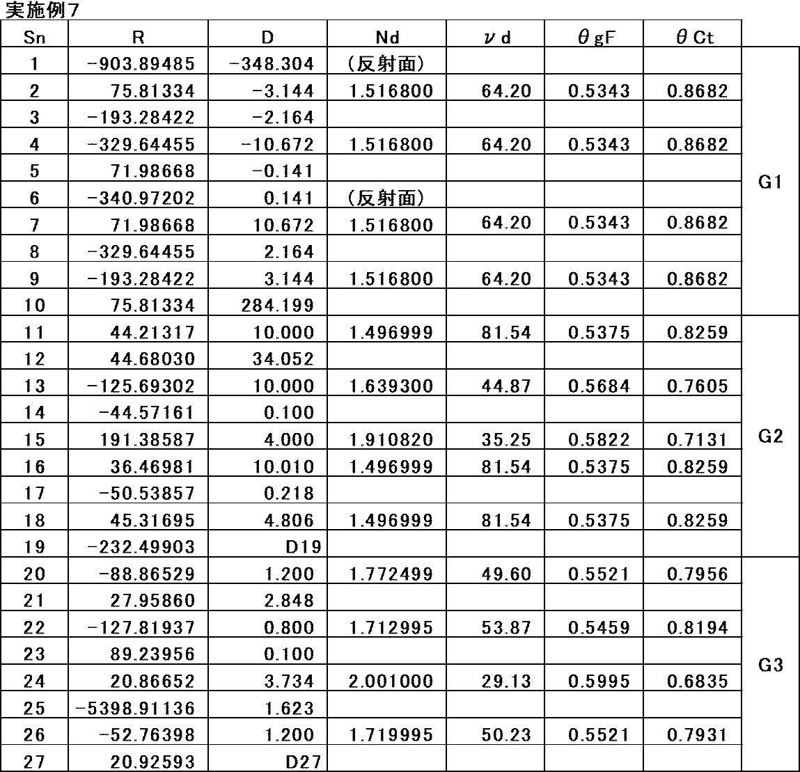


表16に実施例1~7の変倍光学系の条件式(1)~(11)の対応値を示す。表16中の部分分散比以外の対応値は、d線基準での値である。

以上のデータからわかるように、実施例1~7の変倍光学系は、反射屈折光学系であり、望遠端での焦点距離が1000mm(ミリメートル)以上ありながら、直径が100mm(ミリメートル)を超える大口径の光学素子は1つのみであり軽量化が図られている。また、実施例1~7の変倍光学系は、変倍比が3.9倍以上あり、固定された開口絞りStを有し、上記のような長焦点距離を確保しながら、小型化が図られ、可視光域から近赤外光域までの広い範囲で諸収差が良好に補正されて高い光学性能を実現している。
次に、本開示の実施形態に係る撮像装置について説明する。図17に、本開示の実施形態の撮像装置の一例として、本開示の実施形態に係る変倍光学系1を用いた撮像装置10の概略構成図を示す。撮像装置10としては、例えば、監視カメラ、ビデオカメラ、および電子スチルカメラ等を挙げることができる。
撮像装置10は、変倍光学系1と、変倍光学系1の像側に配置されたフィルタ4と、フィルタ4の像側に配置された撮像素子5と、撮像素子5からの出力信号を演算処理する信号処理部6と、変倍光学系1の変倍を制御する変倍制御部7とを備える。
撮像素子5は、変倍光学系1により形成される光学像を電気信号に変換する。撮像素子5としては例えばCCD(Charge Coupled Device)又はCMOS(Complementary Metal Oxide Semiconductor)等を用いることができる。撮像素子5は、その撮像面が変倍光学系1の像面に一致するように配置される。なお、図17では1つの撮像素子5のみ図示しているが、撮像装置10は複数の撮像素子を備えるように構成してもよい。
以上、実施形態および実施例を挙げて本開示の技術を説明したが、本開示の技術は上記実施形態および実施例に限定されず、種々の変形が可能である。例えば、各光学素子の曲率半径、面間隔、屈折率、アッベ数、および非球面係数等は、上記各数値実施例で示した値に限定されず、他の値をとり得る。
本明細書に記載された全ての文献、特許出願、および技術規格は、個々の文献、特許出願、および技術規格が参照により取り込まれることが具体的かつ個々に記された場合と同程度に、本明細書中に参照により取り込まれる。
Claims (20)
- 光路に沿って物体側から像側へ順に、正のパワーを有する第1群と、正のパワーを有する第2群と、負のパワーを有する第3群と、正のパワーを有する第4群と、正のパワーを有する第5群とからなる5つの群のみをパワーを有する群として備え、
前記第1群は、光路上で最も物体側に位置するパワーを有する光学素子であり、かつ凹面形状の反射面を物体側に向けた第1ミラーと、前記第1ミラーから物体側へ向かう光を像側へ反射する、凸面形状の反射面を像側に向けた第2ミラーとを含み、
前記第1群と前記第2群との間の光路に中間像が形成され、
前記第2群と前記第3群と前記第4群とは屈折光学系であり、
前記第3群と前記第4群との間に絞りが配置され、
広角端から望遠端への変倍の際に、前記第1ミラーと、前記第2ミラーと、前記第2群と、前記絞りと、前記第5群とは像面に対して固定されており、前記第3群は像側へ移動し、前記第4群は物体側へ移動する変倍光学系。 - 変倍の際に前記第1群は像面に対して固定されており、
望遠端での前記変倍光学系の焦点距離をfT、
前記第1群の焦点距離をf1とした場合、
0.5<|fT/f1|<4 (1)
で表される条件式(1)を満足する請求項1に記載の変倍光学系。 - 変倍の際に前記第1群は像面に対して固定されており、
無限遠物体に合焦した状態における前記第2群の横倍率をβ2とした場合、
-2<β2<-0.5 (2)
で表される条件式(2)を満足する請求項1又は2に記載の変倍光学系。 - 前記第3群の焦点距離をf3、
前記第4群の焦点距離をf4とした場合、
-2<f3/f4<-0.1 (3)
で表される条件式(3)を満足する請求項1から3のいずれか1項に記載の変倍光学系。 - 前記第4群は、最も物体側に配置された両凸レンズと、前記両凸レンズより像側に配置されて正レンズと負レンズとの2枚のレンズが接合されて構成された接合レンズとを含む請求項1から4のいずれか1項に記載の変倍光学系。
- 無限遠物体に合焦した状態において、
望遠端での前記第3群の横倍率をβ3T、
広角端での前記第3群の横倍率をβ3Wとした場合、
1<β3T/β3W<5 (4)
で表される条件式(4)を満足する請求項1から5のいずれか1項に記載の変倍光学系。 - 無限遠物体に合焦した状態において、
望遠端での前記第4群の横倍率をβ4T、
広角端での前記第4群の横倍率をβ4Wとした場合、
1<β4T/β4W<5 (5)
で表される条件式(5)を満足する請求項1から6のいずれか1項に記載の変倍光学系。 - 無限遠物体に合焦した状態において、
望遠端での前記第3群の横倍率をβ3T、
広角端での前記第3群の横倍率をβ3W、
望遠端での前記第4群の横倍率をβ4T、
広角端での前記第4群の横倍率をβ4Wとした場合、
0.25<(β3T/β3W)/(β4T/β4W)<2 (6)
で表される条件式(6)を満足する請求項1から7のいずれか1項に記載の変倍光学系。 - 無限遠物体に合焦した状態における広角端での前記第5群の横倍率をβ5Wとした場合、
1<β5W<3 (7)
で表される条件式(7)を満足する請求項1から8のいずれか1項に記載の変倍光学系。 - 前記第1ミラーの反射面および前記第2ミラーの反射面は球面形状であり、
前記第1群は前記第2ミラーと前記中間像との間の光路に少なくとも1枚の球面レンズを含む請求項1から9のいずれか1項に記載の変倍光学系。 - 前記第2群の全ての正レンズのg線とF線間の部分分散比の平均をθgF2P、
前記第2群の全ての負レンズのg線とF線間の部分分散比の平均をθgF2Nとした場合、
-0.15<θgF2P-θgF2N<-0.005 (8)
で表される条件式(8)を満足する請求項1から10のいずれか1項に記載の変倍光学系。 - 前記第2群の全ての正レンズのC線とt線間の部分分散比の平均をθCt2P、
前記第2群の全ての負レンズのC線とt線間の部分分散比の平均をθCt2Nとした場合、
0.01<θCt2P-θCt2N<0.3 (9)
で表される条件式(9)を満足する請求項1から11のいずれか1項に記載の変倍光学系。 - 前記第4群の全ての正レンズのg線とF線間の部分分散比の平均をθgF4P、
前記第4群の全ての負レンズのg線とF線間の部分分散比の平均をθgF4Nとした場合、
-0.15<θgF4P-θgF4N<-0.005 (10)
で表される条件式(10)を満足する請求項1から12のいずれか1項に記載の変倍光学系。 - 前記第4群の全ての正レンズのC線とt線間の部分分散比の平均をθCt4P、
前記第4群の全ての負レンズのC線とt線間の部分分散比の平均をθCt4Nとした場合、
0.01<θCt4P-θCt4N<0.3 (11)
で表される条件式(11)を満足する請求項1から13のいずれか1項に記載の変倍光学系。 - 1<|fT/f1|<2.5 (1-1)
で表される条件式(1-1)を満足する請求項2に記載の変倍光学系。 - -1.5<β2<-1 (2-1)
で表される条件式(2-1)を満足する請求項3に記載の変倍光学系。 - -1<f3/f4<-0.5 (3-1)
で表される条件式(3-1)を満足する請求項4に記載の変倍光学系。 - 1.2<β3T/β3W<3.5 (4-1)
で表される条件式(4-1)を満足する請求項6に記載の変倍光学系。 - 1.2<β4T/β4W<3 (5-1)
で表される条件式(5-1)を満足する請求項7に記載の変倍光学系。 - 請求項1から19のいずれか1項に記載の変倍光学系を備えた撮像装置。
Priority Applications (3)
| Application Number | Priority Date | Filing Date | Title |
|---|---|---|---|
| CN202080075162.5A CN114600027B (zh) | 2019-10-29 | 2020-10-14 | 变倍光学系统及摄像装置 |
| JP2021554326A JP7109686B2 (ja) | 2019-10-29 | 2020-10-14 | 変倍光学系および撮像装置 |
| US17/729,642 US12050311B2 (en) | 2019-10-29 | 2022-04-26 | Variable magnification optical system and imaging apparatus |
Applications Claiming Priority (2)
| Application Number | Priority Date | Filing Date | Title |
|---|---|---|---|
| JP2019196725 | 2019-10-29 | ||
| JP2019-196725 | 2019-10-29 |
Related Child Applications (1)
| Application Number | Title | Priority Date | Filing Date |
|---|---|---|---|
| US17/729,642 Continuation US12050311B2 (en) | 2019-10-29 | 2022-04-26 | Variable magnification optical system and imaging apparatus |
Publications (1)
| Publication Number | Publication Date |
|---|---|
| WO2021085142A1 true WO2021085142A1 (ja) | 2021-05-06 |
Family
ID=75716267
Family Applications (1)
| Application Number | Title | Priority Date | Filing Date |
|---|---|---|---|
| PCT/JP2020/038809 Ceased WO2021085142A1 (ja) | 2019-10-29 | 2020-10-14 | 変倍光学系および撮像装置 |
Country Status (4)
| Country | Link |
|---|---|
| US (1) | US12050311B2 (ja) |
| JP (1) | JP7109686B2 (ja) |
| CN (1) | CN114600027B (ja) |
| WO (1) | WO2021085142A1 (ja) |
Cited By (1)
| Publication number | Priority date | Publication date | Assignee | Title |
|---|---|---|---|---|
| JPWO2022138054A1 (ja) * | 2020-12-21 | 2022-06-30 |
Families Citing this family (3)
| Publication number | Priority date | Publication date | Assignee | Title |
|---|---|---|---|---|
| JP7401265B2 (ja) * | 2019-11-07 | 2023-12-19 | キヤノン株式会社 | 光学系および光学機器 |
| CN116413894B (zh) * | 2021-12-31 | 2026-02-24 | 中国科学院长春光学精密机械与物理研究所 | 一折反式共口径三档变焦光学系统 |
| CN117355781A (zh) * | 2022-05-05 | 2024-01-05 | 北京小米移动软件有限公司 | 光学系统、以及具备光学系统的拍摄装置 |
Citations (5)
| Publication number | Priority date | Publication date | Assignee | Title |
|---|---|---|---|---|
| US4971428A (en) * | 1989-03-27 | 1990-11-20 | Lenzar Optics Corporation | Catadioptric zoom lens |
| JPH11202208A (ja) * | 1997-10-27 | 1999-07-30 | Wescam Inc | 反射屈折光学系ズームレンズ組立体 |
| US20050259330A1 (en) * | 2005-07-29 | 2005-11-24 | Panavision International, L.P. | Zoom lens system |
| JP2017187640A (ja) * | 2016-04-06 | 2017-10-12 | オリンパス株式会社 | 変倍光学系及びそれを備えた撮像装置 |
| JP2019148791A (ja) * | 2018-02-27 | 2019-09-05 | 富士フイルム株式会社 | 変倍光学系及び撮像装置 |
Family Cites Families (6)
| Publication number | Priority date | Publication date | Assignee | Title |
|---|---|---|---|---|
| EP2899581B1 (en) * | 2012-09-20 | 2017-08-23 | Nittoh Inc. | Zoom lens system and image-capturing device |
| US10558025B2 (en) | 2016-04-06 | 2020-02-11 | Olympus Corporation | Variable magnification optical system and image pickup apparatus using the same |
| JP6678604B2 (ja) * | 2017-01-05 | 2020-04-08 | 富士フイルム株式会社 | ズームレンズおよび撮像装置 |
| CN106772963B (zh) * | 2017-01-26 | 2019-03-29 | 西安应用光学研究所 | 全球面大口径折反式连续变焦光学系统 |
| US10948701B2 (en) * | 2018-02-27 | 2021-03-16 | Fujifilm Corporation | Variable magnification optical system and imaging apparatus |
| US11221470B2 (en) * | 2018-02-27 | 2022-01-11 | Fujifilm Corporation | Variable magnification optical system and imaging apparatus |
-
2020
- 2020-10-14 WO PCT/JP2020/038809 patent/WO2021085142A1/ja not_active Ceased
- 2020-10-14 CN CN202080075162.5A patent/CN114600027B/zh active Active
- 2020-10-14 JP JP2021554326A patent/JP7109686B2/ja active Active
-
2022
- 2022-04-26 US US17/729,642 patent/US12050311B2/en active Active
Patent Citations (5)
| Publication number | Priority date | Publication date | Assignee | Title |
|---|---|---|---|---|
| US4971428A (en) * | 1989-03-27 | 1990-11-20 | Lenzar Optics Corporation | Catadioptric zoom lens |
| JPH11202208A (ja) * | 1997-10-27 | 1999-07-30 | Wescam Inc | 反射屈折光学系ズームレンズ組立体 |
| US20050259330A1 (en) * | 2005-07-29 | 2005-11-24 | Panavision International, L.P. | Zoom lens system |
| JP2017187640A (ja) * | 2016-04-06 | 2017-10-12 | オリンパス株式会社 | 変倍光学系及びそれを備えた撮像装置 |
| JP2019148791A (ja) * | 2018-02-27 | 2019-09-05 | 富士フイルム株式会社 | 変倍光学系及び撮像装置 |
Cited By (3)
| Publication number | Priority date | Publication date | Assignee | Title |
|---|---|---|---|---|
| JPWO2022138054A1 (ja) * | 2020-12-21 | 2022-06-30 | ||
| WO2022138054A1 (ja) * | 2020-12-21 | 2022-06-30 | 富士フイルム株式会社 | 変倍光学系および撮像装置 |
| JP7317252B2 (ja) | 2020-12-21 | 2023-07-28 | 富士フイルム株式会社 | 変倍光学系および撮像装置 |
Also Published As
| Publication number | Publication date |
|---|---|
| CN114600027A (zh) | 2022-06-07 |
| JPWO2021085142A1 (ja) | 2021-05-06 |
| US20220308326A1 (en) | 2022-09-29 |
| CN114600027B (zh) | 2023-11-14 |
| JP7109686B2 (ja) | 2022-07-29 |
| US12050311B2 (en) | 2024-07-30 |
Similar Documents
| Publication | Publication Date | Title |
|---|---|---|
| JP6820878B2 (ja) | ズームレンズ及び撮像装置 | |
| JP5694508B2 (ja) | 変倍光学系および撮像装置 | |
| CN110501810B (zh) | 光学系统和摄像装置 | |
| JP7061980B2 (ja) | ズームレンズおよび撮像装置 | |
| JP7109686B2 (ja) | 変倍光学系および撮像装置 | |
| KR20230003216A (ko) | 렌즈 광학계 | |
| JP2018120152A (ja) | ズームレンズおよび撮像装置 | |
| JP7167000B2 (ja) | ズームレンズおよび撮像装置 | |
| CN110196489B (zh) | 变倍光学系统及摄像装置 | |
| JP6493896B2 (ja) | ズームレンズおよび撮像装置 | |
| JP7321127B2 (ja) | ズームレンズ及び撮像装置 | |
| JP2017146519A (ja) | 撮像レンズおよび撮像装置 | |
| JP2017116919A (ja) | ズームレンズ系、撮像装置 | |
| JP5841675B2 (ja) | ズームレンズおよび撮像装置 | |
| JP4817551B2 (ja) | ズームレンズ | |
| CN112859310A (zh) | 变焦镜头及摄像装置 | |
| JP7314200B2 (ja) | 変倍光学系および撮像装置 | |
| JP6815376B2 (ja) | 変倍光学系及び撮像装置 | |
| JP6815375B2 (ja) | 変倍光学系及び撮像装置 | |
| CN111061049B (zh) | 变焦镜头及摄像装置 | |
| JP2018109711A (ja) | ズームレンズおよび撮像装置 | |
| JP7420903B2 (ja) | 撮像レンズおよび撮像装置 | |
| JP7666992B2 (ja) | ズームレンズおよび撮像装置 | |
| JP2025018369A (ja) | ズームレンズおよび撮像装置 | |
| JP7317252B2 (ja) | 変倍光学系および撮像装置 |
Legal Events
| Date | Code | Title | Description |
|---|---|---|---|
| 121 | Ep: the epo has been informed by wipo that ep was designated in this application |
Ref document number: 20881705 Country of ref document: EP Kind code of ref document: A1 |
|
| ENP | Entry into the national phase |
Ref document number: 2021554326 Country of ref document: JP Kind code of ref document: A |
|
| NENP | Non-entry into the national phase |
Ref country code: DE |
|
| 122 | Ep: pct application non-entry in european phase |
Ref document number: 20881705 Country of ref document: EP Kind code of ref document: A1 |