WO2021085135A1 - 医療用ポンプ、医療用ポンプの制御方法、及び、医療用ポンプシステム - Google Patents
医療用ポンプ、医療用ポンプの制御方法、及び、医療用ポンプシステム Download PDFInfo
- Publication number
- WO2021085135A1 WO2021085135A1 PCT/JP2020/038755 JP2020038755W WO2021085135A1 WO 2021085135 A1 WO2021085135 A1 WO 2021085135A1 JP 2020038755 W JP2020038755 W JP 2020038755W WO 2021085135 A1 WO2021085135 A1 WO 2021085135A1
- Authority
- WO
- WIPO (PCT)
- Prior art keywords
- identification information
- drug
- medical pump
- information
- tag
- Prior art date
Links
- 238000000034 method Methods 0.000 title claims description 25
- 238000004891 communication Methods 0.000 claims abstract description 37
- 239000003814 drug Substances 0.000 claims description 209
- 229940079593 drug Drugs 0.000 claims description 207
- 238000001647 drug administration Methods 0.000 claims description 6
- 230000010365 information processing Effects 0.000 description 17
- 229940071643 prefilled syringe Drugs 0.000 description 13
- 238000010586 diagram Methods 0.000 description 10
- 238000001802 infusion Methods 0.000 description 10
- 238000009434 installation Methods 0.000 description 10
- 230000008569 process Effects 0.000 description 9
- 238000012806 monitoring device Methods 0.000 description 8
- 230000005856 abnormality Effects 0.000 description 5
- 238000007726 management method Methods 0.000 description 5
- 238000012545 processing Methods 0.000 description 5
- 238000001514 detection method Methods 0.000 description 4
- VYFYYTLLBUKUHU-UHFFFAOYSA-N dopamine Chemical compound NCCC1=CC=C(O)C(O)=C1 VYFYYTLLBUKUHU-UHFFFAOYSA-N 0.000 description 4
- 239000007788 liquid Substances 0.000 description 4
- SNIOPGDIGTZGOP-UHFFFAOYSA-N Nitroglycerin Chemical compound [O-][N+](=O)OCC(O[N+]([O-])=O)CO[N+]([O-])=O SNIOPGDIGTZGOP-UHFFFAOYSA-N 0.000 description 3
- 239000000006 Nitroglycerin Substances 0.000 description 3
- 230000005540 biological transmission Effects 0.000 description 3
- 229960003711 glyceryl trinitrate Drugs 0.000 description 3
- 239000002869 intravenous anesthetic agent Substances 0.000 description 3
- 230000004044 response Effects 0.000 description 3
- 239000002550 vasoactive agent Substances 0.000 description 3
- SFLSHLFXELFNJZ-QMMMGPOBSA-N (-)-norepinephrine Chemical compound NC[C@H](O)C1=CC=C(O)C(O)=C1 SFLSHLFXELFNJZ-QMMMGPOBSA-N 0.000 description 2
- UCTWMZQNUQWSLP-VIFPVBQESA-N (R)-adrenaline Chemical compound CNC[C@H](O)C1=CC=C(O)C(O)=C1 UCTWMZQNUQWSLP-VIFPVBQESA-N 0.000 description 2
- 229930182837 (R)-adrenaline Natural products 0.000 description 2
- JRWZLRBJNMZMFE-UHFFFAOYSA-N Dobutamine Chemical compound C=1C=C(O)C(O)=CC=1CCNC(C)CCC1=CC=C(O)C=C1 JRWZLRBJNMZMFE-UHFFFAOYSA-N 0.000 description 2
- ZTVQQQVZCWLTDF-UHFFFAOYSA-N Remifentanil Chemical compound C1CN(CCC(=O)OC)CCC1(C(=O)OC)N(C(=O)CC)C1=CC=CC=C1 ZTVQQQVZCWLTDF-UHFFFAOYSA-N 0.000 description 2
- 230000003444 anaesthetic effect Effects 0.000 description 2
- 239000002246 antineoplastic agent Substances 0.000 description 2
- 239000003795 chemical substances by application Substances 0.000 description 2
- 229960001089 dobutamine Drugs 0.000 description 2
- 229960003638 dopamine Drugs 0.000 description 2
- 229960005139 epinephrine Drugs 0.000 description 2
- 230000006870 function Effects 0.000 description 2
- 238000001990 intravenous administration Methods 0.000 description 2
- MOYKHGMNXAOIAT-JGWLITMVSA-N isosorbide dinitrate Chemical compound [O-][N+](=O)O[C@H]1CO[C@@H]2[C@H](O[N+](=O)[O-])CO[C@@H]21 MOYKHGMNXAOIAT-JGWLITMVSA-N 0.000 description 2
- 229960000201 isosorbide dinitrate Drugs 0.000 description 2
- -1 mitazolam Chemical compound 0.000 description 2
- 229960002748 norepinephrine Drugs 0.000 description 2
- SFLSHLFXELFNJZ-UHFFFAOYSA-N norepinephrine Natural products NCC(O)C1=CC=C(O)C(O)=C1 SFLSHLFXELFNJZ-UHFFFAOYSA-N 0.000 description 2
- OLBCVFGFOZPWHH-UHFFFAOYSA-N propofol Chemical compound CC(C)C1=CC=CC(C(C)C)=C1O OLBCVFGFOZPWHH-UHFFFAOYSA-N 0.000 description 2
- 229960004134 propofol Drugs 0.000 description 2
- 229960003394 remifentanil Drugs 0.000 description 2
- HBBGRARXTFLTSG-UHFFFAOYSA-N Lithium ion Chemical compound [Li+] HBBGRARXTFLTSG-UHFFFAOYSA-N 0.000 description 1
- 230000002159 abnormal effect Effects 0.000 description 1
- 230000004308 accommodation Effects 0.000 description 1
- 239000000853 adhesive Substances 0.000 description 1
- 230000001070 adhesive effect Effects 0.000 description 1
- 230000000202 analgesic effect Effects 0.000 description 1
- 229940035674 anesthetics Drugs 0.000 description 1
- 238000012550 audit Methods 0.000 description 1
- 238000012790 confirmation Methods 0.000 description 1
- 229940127089 cytotoxic agent Drugs 0.000 description 1
- 239000000645 desinfectant Substances 0.000 description 1
- 239000012530 fluid Substances 0.000 description 1
- 239000003193 general anesthetic agent Substances 0.000 description 1
- 239000004973 liquid crystal related substance Substances 0.000 description 1
- 229910001416 lithium ion Inorganic materials 0.000 description 1
- 239000000463 material Substances 0.000 description 1
- 230000007246 mechanism Effects 0.000 description 1
- 238000012986 modification Methods 0.000 description 1
- 230000004048 modification Effects 0.000 description 1
- 210000000653 nervous system Anatomy 0.000 description 1
- 235000016709 nutrition Nutrition 0.000 description 1
- 238000011160 research Methods 0.000 description 1
- 239000011347 resin Substances 0.000 description 1
- 229920005989 resin Polymers 0.000 description 1
- 238000007789 sealing Methods 0.000 description 1
- 239000000932 sedative agent Substances 0.000 description 1
- 230000001624 sedative effect Effects 0.000 description 1
- 239000004065 semiconductor Substances 0.000 description 1
- 239000000126 substance Substances 0.000 description 1
- 230000002227 vasoactive effect Effects 0.000 description 1
Images


Classifications
-
- G—PHYSICS
- G16—INFORMATION AND COMMUNICATION TECHNOLOGY [ICT] SPECIALLY ADAPTED FOR SPECIFIC APPLICATION FIELDS
- G16H—HEALTHCARE INFORMATICS, i.e. INFORMATION AND COMMUNICATION TECHNOLOGY [ICT] SPECIALLY ADAPTED FOR THE HANDLING OR PROCESSING OF MEDICAL OR HEALTHCARE DATA
- G16H20/00—ICT specially adapted for therapies or health-improving plans, e.g. for handling prescriptions, for steering therapy or for monitoring patient compliance
- G16H20/10—ICT specially adapted for therapies or health-improving plans, e.g. for handling prescriptions, for steering therapy or for monitoring patient compliance relating to drugs or medications, e.g. for ensuring correct administration to patients
- G16H20/17—ICT specially adapted for therapies or health-improving plans, e.g. for handling prescriptions, for steering therapy or for monitoring patient compliance relating to drugs or medications, e.g. for ensuring correct administration to patients delivered via infusion or injection
-
- A—HUMAN NECESSITIES
- A61—MEDICAL OR VETERINARY SCIENCE; HYGIENE
- A61M—DEVICES FOR INTRODUCING MEDIA INTO, OR ONTO, THE BODY; DEVICES FOR TRANSDUCING BODY MEDIA OR FOR TAKING MEDIA FROM THE BODY; DEVICES FOR PRODUCING OR ENDING SLEEP OR STUPOR
- A61M5/00—Devices for bringing media into the body in a subcutaneous, intra-vascular or intramuscular way; Accessories therefor, e.g. filling or cleaning devices, arm-rests
- A61M5/14—Infusion devices, e.g. infusing by gravity; Blood infusion; Accessories therefor
- A61M5/142—Pressure infusion, e.g. using pumps
- A61M5/145—Pressure infusion, e.g. using pumps using pressurised reservoirs, e.g. pressurised by means of pistons
- A61M5/1452—Pressure infusion, e.g. using pumps using pressurised reservoirs, e.g. pressurised by means of pistons pressurised by means of pistons
- A61M5/14546—Front-loading type injectors
-
- A—HUMAN NECESSITIES
- A61—MEDICAL OR VETERINARY SCIENCE; HYGIENE
- A61M—DEVICES FOR INTRODUCING MEDIA INTO, OR ONTO, THE BODY; DEVICES FOR TRANSDUCING BODY MEDIA OR FOR TAKING MEDIA FROM THE BODY; DEVICES FOR PRODUCING OR ENDING SLEEP OR STUPOR
- A61M5/00—Devices for bringing media into the body in a subcutaneous, intra-vascular or intramuscular way; Accessories therefor, e.g. filling or cleaning devices, arm-rests
- A61M5/14—Infusion devices, e.g. infusing by gravity; Blood infusion; Accessories therefor
- A61M5/142—Pressure infusion, e.g. using pumps
-
- G—PHYSICS
- G06—COMPUTING; CALCULATING OR COUNTING
- G06K—GRAPHICAL DATA READING; PRESENTATION OF DATA; RECORD CARRIERS; HANDLING RECORD CARRIERS
- G06K7/00—Methods or arrangements for sensing record carriers, e.g. for reading patterns
- G06K7/10—Methods or arrangements for sensing record carriers, e.g. for reading patterns by electromagnetic radiation, e.g. optical sensing; by corpuscular radiation
- G06K7/10009—Methods or arrangements for sensing record carriers, e.g. for reading patterns by electromagnetic radiation, e.g. optical sensing; by corpuscular radiation sensing by radiation using wavelengths larger than 0.1 mm, e.g. radio-waves or microwaves
- G06K7/10366—Methods or arrangements for sensing record carriers, e.g. for reading patterns by electromagnetic radiation, e.g. optical sensing; by corpuscular radiation sensing by radiation using wavelengths larger than 0.1 mm, e.g. radio-waves or microwaves the interrogation device being adapted for miscellaneous applications
-
- G—PHYSICS
- G16—INFORMATION AND COMMUNICATION TECHNOLOGY [ICT] SPECIALLY ADAPTED FOR SPECIFIC APPLICATION FIELDS
- G16H—HEALTHCARE INFORMATICS, i.e. INFORMATION AND COMMUNICATION TECHNOLOGY [ICT] SPECIALLY ADAPTED FOR THE HANDLING OR PROCESSING OF MEDICAL OR HEALTHCARE DATA
- G16H40/00—ICT specially adapted for the management or administration of healthcare resources or facilities; ICT specially adapted for the management or operation of medical equipment or devices
- G16H40/60—ICT specially adapted for the management or administration of healthcare resources or facilities; ICT specially adapted for the management or operation of medical equipment or devices for the operation of medical equipment or devices
- G16H40/63—ICT specially adapted for the management or administration of healthcare resources or facilities; ICT specially adapted for the management or operation of medical equipment or devices for the operation of medical equipment or devices for local operation
-
- G—PHYSICS
- G16—INFORMATION AND COMMUNICATION TECHNOLOGY [ICT] SPECIALLY ADAPTED FOR SPECIFIC APPLICATION FIELDS
- G16H—HEALTHCARE INFORMATICS, i.e. INFORMATION AND COMMUNICATION TECHNOLOGY [ICT] SPECIALLY ADAPTED FOR THE HANDLING OR PROCESSING OF MEDICAL OR HEALTHCARE DATA
- G16H40/00—ICT specially adapted for the management or administration of healthcare resources or facilities; ICT specially adapted for the management or operation of medical equipment or devices
- G16H40/60—ICT specially adapted for the management or administration of healthcare resources or facilities; ICT specially adapted for the management or operation of medical equipment or devices for the operation of medical equipment or devices
- G16H40/67—ICT specially adapted for the management or administration of healthcare resources or facilities; ICT specially adapted for the management or operation of medical equipment or devices for the operation of medical equipment or devices for remote operation
-
- A—HUMAN NECESSITIES
- A61—MEDICAL OR VETERINARY SCIENCE; HYGIENE
- A61M—DEVICES FOR INTRODUCING MEDIA INTO, OR ONTO, THE BODY; DEVICES FOR TRANSDUCING BODY MEDIA OR FOR TAKING MEDIA FROM THE BODY; DEVICES FOR PRODUCING OR ENDING SLEEP OR STUPOR
- A61M5/00—Devices for bringing media into the body in a subcutaneous, intra-vascular or intramuscular way; Accessories therefor, e.g. filling or cleaning devices, arm-rests
- A61M5/14—Infusion devices, e.g. infusing by gravity; Blood infusion; Accessories therefor
- A61M5/142—Pressure infusion, e.g. using pumps
- A61M2005/14208—Pressure infusion, e.g. using pumps with a programmable infusion control system, characterised by the infusion program
-
- A—HUMAN NECESSITIES
- A61—MEDICAL OR VETERINARY SCIENCE; HYGIENE
- A61M—DEVICES FOR INTRODUCING MEDIA INTO, OR ONTO, THE BODY; DEVICES FOR TRANSDUCING BODY MEDIA OR FOR TAKING MEDIA FROM THE BODY; DEVICES FOR PRODUCING OR ENDING SLEEP OR STUPOR
- A61M2205/00—General characteristics of the apparatus
- A61M2205/33—Controlling, regulating or measuring
-
- A—HUMAN NECESSITIES
- A61—MEDICAL OR VETERINARY SCIENCE; HYGIENE
- A61M—DEVICES FOR INTRODUCING MEDIA INTO, OR ONTO, THE BODY; DEVICES FOR TRANSDUCING BODY MEDIA OR FOR TAKING MEDIA FROM THE BODY; DEVICES FOR PRODUCING OR ENDING SLEEP OR STUPOR
- A61M2205/00—General characteristics of the apparatus
- A61M2205/35—Communication
- A61M2205/3546—Range
- A61M2205/3569—Range sublocal, e.g. between console and disposable
-
- A—HUMAN NECESSITIES
- A61—MEDICAL OR VETERINARY SCIENCE; HYGIENE
- A61M—DEVICES FOR INTRODUCING MEDIA INTO, OR ONTO, THE BODY; DEVICES FOR TRANSDUCING BODY MEDIA OR FOR TAKING MEDIA FROM THE BODY; DEVICES FOR PRODUCING OR ENDING SLEEP OR STUPOR
- A61M2205/00—General characteristics of the apparatus
- A61M2205/35—Communication
- A61M2205/3576—Communication with non implanted data transmission devices, e.g. using external transmitter or receiver
- A61M2205/3584—Communication with non implanted data transmission devices, e.g. using external transmitter or receiver using modem, internet or bluetooth
-
- A—HUMAN NECESSITIES
- A61—MEDICAL OR VETERINARY SCIENCE; HYGIENE
- A61M—DEVICES FOR INTRODUCING MEDIA INTO, OR ONTO, THE BODY; DEVICES FOR TRANSDUCING BODY MEDIA OR FOR TAKING MEDIA FROM THE BODY; DEVICES FOR PRODUCING OR ENDING SLEEP OR STUPOR
- A61M2205/00—General characteristics of the apparatus
- A61M2205/60—General characteristics of the apparatus with identification means
- A61M2205/6054—Magnetic identification systems
-
- A—HUMAN NECESSITIES
- A61—MEDICAL OR VETERINARY SCIENCE; HYGIENE
- A61M—DEVICES FOR INTRODUCING MEDIA INTO, OR ONTO, THE BODY; DEVICES FOR TRANSDUCING BODY MEDIA OR FOR TAKING MEDIA FROM THE BODY; DEVICES FOR PRODUCING OR ENDING SLEEP OR STUPOR
- A61M5/00—Devices for bringing media into the body in a subcutaneous, intra-vascular or intramuscular way; Accessories therefor, e.g. filling or cleaning devices, arm-rests
- A61M5/14—Infusion devices, e.g. infusing by gravity; Blood infusion; Accessories therefor
- A61M5/142—Pressure infusion, e.g. using pumps
- A61M5/145—Pressure infusion, e.g. using pumps using pressurised reservoirs, e.g. pressurised by means of pistons
- A61M5/1452—Pressure infusion, e.g. using pumps using pressurised reservoirs, e.g. pressurised by means of pistons pressurised by means of pistons
- A61M5/1456—Pressure infusion, e.g. using pumps using pressurised reservoirs, e.g. pressurised by means of pistons pressurised by means of pistons with a replaceable reservoir comprising a piston rod to be moved into the reservoir, e.g. the piston rod is part of the removable reservoir
-
- G—PHYSICS
- G06—COMPUTING; CALCULATING OR COUNTING
- G06K—GRAPHICAL DATA READING; PRESENTATION OF DATA; RECORD CARRIERS; HANDLING RECORD CARRIERS
- G06K7/00—Methods or arrangements for sensing record carriers, e.g. for reading patterns
- G06K7/10—Methods or arrangements for sensing record carriers, e.g. for reading patterns by electromagnetic radiation, e.g. optical sensing; by corpuscular radiation
- G06K7/10009—Methods or arrangements for sensing record carriers, e.g. for reading patterns by electromagnetic radiation, e.g. optical sensing; by corpuscular radiation sensing by radiation using wavelengths larger than 0.1 mm, e.g. radio-waves or microwaves
- G06K7/10366—Methods or arrangements for sensing record carriers, e.g. for reading patterns by electromagnetic radiation, e.g. optical sensing; by corpuscular radiation sensing by radiation using wavelengths larger than 0.1 mm, e.g. radio-waves or microwaves the interrogation device being adapted for miscellaneous applications
- G06K7/10376—Methods or arrangements for sensing record carriers, e.g. for reading patterns by electromagnetic radiation, e.g. optical sensing; by corpuscular radiation sensing by radiation using wavelengths larger than 0.1 mm, e.g. radio-waves or microwaves the interrogation device being adapted for miscellaneous applications the interrogation device being adapted for being moveable
- G06K7/10386—Methods or arrangements for sensing record carriers, e.g. for reading patterns by electromagnetic radiation, e.g. optical sensing; by corpuscular radiation sensing by radiation using wavelengths larger than 0.1 mm, e.g. radio-waves or microwaves the interrogation device being adapted for miscellaneous applications the interrogation device being adapted for being moveable the interrogation device being of the portable or hand-handheld type, e.g. incorporated in ubiquitous hand-held devices such as PDA or mobile phone, or in the form of a portable dedicated RFID reader
Definitions
- This disclosure relates to a medical pump, a control method for a medical pump, and a medical pump system.
- Medical pumps such as syringe pumps and infusion pumps are used, for example, in operating rooms and intensive care units (ICUs). Medical pumps are used when administering drugs such as anticancer agents, anesthetics, chemotherapeutic agents, and nutritional agents to patients with high accuracy for a relatively long period of time.
- drugs such as anticancer agents, anesthetics, chemotherapeutic agents, and nutritional agents to patients with high accuracy for a relatively long period of time.
- a method using a drug library is known in order to suppress administration of a drug with an incorrect setting when administering a drug with a medical pump (see, for example, Patent Document 1).
- the drug library is, for example, a database of setting information and the like at the time of administration for each of several thousand kinds of drugs.
- each drug has drug-specific setting information such as reference administration rate, upper / lower limit of administration rate, drug code, and drug color.
- a method has been proposed in which a drug library is stored in a medical pump and a drug is administered according to drug-specific setting information using an RF (radio frequency) tag attached to a syringe filled with the drug (for example). , See Reference 2).
- the medical pump reads out the drug identification information stored in the RF tag, and sets information on the administration of the drug such as the administration rate based on the drug-specific setting information corresponding to the drug identification information.
- the drug-specific information is information that can identify a drug, for example, a drug code.
- the RF tag By using the RF tag, it is possible to automate and speed up the acquisition of setting information corresponding to the medicine contained in the syringe container and the infusion container used for the medical pump in a medical institution such as a hospital. In addition, by using RF tags, it can be expected to suppress erroneous administration of drugs due to human error. Therefore, it is expected that RF tags will be used in medical pumps in the future.
- the drug used in the medical pump may be provided by the drug manufacturer as a prefilled syringe or the like in which the syringe container is filled with the drug in advance.
- prefilled syringes will be equipped with RF tags in the factories of drug manufacturers for the purpose of logistics management.
- RF tag for physical distribution management, it is considered that a standard code such as SGTIN (Serialized Global Trade Item Number) that can uniquely identify an individual item in the world is adopted.
- the RF tag for drug authentication aims to suppress erroneous administration of a drug. It is considered that the RF tag for drug authentication adopts the unique code of the medical institution associated with the prescription information for the patient.
- the standard code and the original code obtained from the RF tag are referred to as identification information because they are information for identifying the drug filled in the drug storage container such as the syringe container and the infusion container to which the RF tag is attached. ..
- two RF tags are read when the medical pump reads out these RF tags.
- Identification information may be read out. When the two identification information is read out, it is necessary to clarify which identification information the medical pump follows to set the information regarding the administration of the drug.
- An object of the present disclosure made in view of such a point is to provide a medical pump, a control method of the medical pump, and a medical pump system capable of appropriately administering a drug when a plurality of identification information is read. There is.
- the medical pump as the first aspect of the present disclosure has a reader capable of reading the identification information stored in the RF tag by wireless communication, and information on administration of the drug based on the identification information read from the RF tag. It is provided with a control unit to be set. When the reader reads the two different identification information, the control unit selects only one of the two different identification information and sets the information regarding the administration.
- the RF tag is attached to a drug storage container that houses the drug.
- the drug storage container is a syringe.
- the control unit uses only the one identification information based on the data of a predetermined area included in the identification information. select.
- control unit when the reader reads the same two identical identification information, the control unit does not set the information regarding the administration.
- the control unit when the reader reads three or more of the identification information, the control unit does not set the information regarding the administration.
- the control unit when the reader reads only one of the identification information, the control unit sets information regarding the administration based on the read identification information.
- the medical pump further includes a display unit that displays information about the administration.
- the identification information includes a first type of identification information and a second type of identification information having different data structures.
- the control unit selects only the second type of identification information.
- the first type of identification information is identification information assigned to the drug
- the second type of identification information is identification associated with prescription information for administering the drug. Information.
- the control unit when the identification information includes the second type of identification information, sets at least a part of the prescription information as information regarding the administration.
- the medical pump further comprises a communication unit that communicates with a server, and the control unit is associated with the identification information of the second type from the server via the communication unit. Acquire the prescription information stored in the server.
- the first type of identification information is identification information uniquely defined according to a standard.
- the second type of identification information is identification information uniquely set by a medical institution.
- the identification information stored in the RF tag is read by wireless communication, and the information regarding the administration of the drug is set based on the identification information read from the RF tag. It is a control method of a medical pump. In this control method, when two different identification information is read, only one identification information is selected from the two different identification information to set the information regarding the administration.
- the medical pump system as the third aspect of the present disclosure is a medical pump system including a drug storage container equipped with an RF tag and a medical pump.
- the drug storage container stores the drug to be administered to the patient.
- the medical pump includes a reader that can read the identification information stored in the RF tag by wireless communication, and a control unit that sets information related to drug administration based on the identification information read from the RF tag. Be prepared. When the reader reads the two different identification information, the control unit selects only one of the two different identification information and sets the information regarding the administration.
- a server is further provided, and the medical pump further includes a communication unit that communicates with the server.
- the identification information includes a first type of identification information and a second type of identification information.
- the server stores information stored in association with the second type of identification information.
- the control unit selects only the second type of identification information.
- the control unit acquires the information stored in association with the identification information of the second type from the server via the communication unit, and sets the information regarding the administration.
- the control method of the medical pump, and the medical pump system according to the present disclosure when a plurality of identification information is read, the information regarding the administration of the drug can be appropriately set.
- FIG. 1 is a schematic configuration diagram of a medical pump system according to an embodiment of the present disclosure.
- FIG. 2 is a diagram showing an example of a system in a medical institution including the medical pump system of FIG.
- FIG. 3 is an overview perspective view showing the medical pump of FIG. 1 in a state where a syringe is attached.
- FIG. 4 is an overview front view of the medical pump shown in FIG.
- FIG. 5 is an overview perspective view of the syringe shown in FIG.
- FIG. 6 is a schematic configuration diagram of the RF tag shown in FIG.
- FIG. 7 is a diagram showing an example of a data structure of a standard code (first type of identification information).
- FIG. 8 is a diagram showing an example of a data structure of a unique code (second type of identification information).
- FIG. 1 is a schematic configuration diagram of a medical pump system according to an embodiment of the present disclosure.
- FIG. 2 is a diagram showing an example of a system in a medical institution including the medical pump
- FIG. 9 is a schematic view showing the electrical configuration of the medical pump shown in FIG.
- FIG. 10 is an example of the display of the display unit of the medical pump shown in FIG.
- FIG. 11 is a flowchart showing an example of a procedure for attaching an RF tag containing the second type of identification information to a syringe.
- FIG. 12 is a flowchart showing an example of the operation of the medical pump of FIG.
- FIG. 13 is a flowchart showing an example of a procedure for setting information regarding administration of a drug to a medical pump based on identification information.
- FIG. 1 is a schematic configuration diagram of a medical pump system 1 according to an embodiment of the present disclosure.
- the medical pump system 1 includes a medical pump 100 and a syringe 200.
- the syringe 200 can be attached to the medical pump 100.
- One or more RF tags 300 are attached to the syringe 200.
- one or more RF tags 300 include a first RF tag 301 and a second RF tag 302.
- the RF tag 300 is a small electronic device that can read information wirelessly.
- the RF tag 300 can receive at least identification information (ID information) by receiving electromagnetic waves from the outside.
- ID information is information that can identify the drug in the syringe 200 to which each RF tag 300 is attached.
- the RF tag 300 is synonymous with an RFID (radio frequency identifier), a wireless tag, and an IC (Integrated Circuit) tag.
- the medical pump 100 and the RF tag 300 can communicate with each other by wireless communication using, for example, a frequency in the UHF (Ultra High Frequency) band or the HF (High Frequency) band.
- the RF tag 300 may adopt an RF tag conforming to the ISO / IEC 18000-63 standard.
- the RF tag 300 is not limited to the RF tag conforming to the ISO / IEC 18000-63 standard.
- the first RF tag 301 is an RF tag that employs a standard code used for physical distribution management and the like.
- the standard code is the first type of identification information.
- Standard codes include, for example, SGTIN.
- SGTIN includes a business code that identifies a business, a product code that identifies a product, and a serial number for each product. Therefore, the standard code contains drug-specific information that identifies the drug.
- the first RF tag 301 can be attached at a factory or the like of a manufacturer that manufactures the prefilled syringe.
- the standard code is an example of the first type of identification information.
- the first type of identification information is not limited to the standard code.
- the second RF tag 302 can be an RF tag that employs a code unique to the medical institution (unique code) that is attached for the purpose of drug authentication within the medical institution.
- the unique code of the medical institution is the second type of identification information.
- a prescription ID for the patient in the medical institution or a code associated with the prescription ID can be used.
- the prescription ID is identification information assigned to prescription information which is an instruction of a method of administering a drug to a patient by a doctor.
- the second RF tag 302 is issued when a drug is dispensed or dispensed in a medical institution, and can be attached to a container for the drug such as a syringe 200.
- the medical institution's unique code is an example of the second type of identification information.
- the second type of identification information is not limited to the unique code of the medical institution.
- the intensity of the electromagnetic wave transmitted by the medical pump 100 to the RF tag 300 is limited to a predetermined intensity or less.
- the RF tag 300 can receive the predetermined strength when the syringe 200 is attached to the medical pump 100, but when the syringe 200 is separated from the medical pump 100 by a predetermined distance or more, the RF tag 300 can be received. Is so strong that it cannot be received. As a result, it is possible to prevent the medical pump 100 from erroneously reading data from the RF tag 300 attached to the syringe 200 that is not attached to the medical pump 100.
- the medical pump 100 may store the drug library.
- the drug library is, for example, a database of drug-specific setting information and the like at the time of administration for each of thousands of drugs.
- each drug has setting information such as a reference administration rate, an upper / lower limit value of the administration rate, a drug code, and a drug color.
- a collection of a plurality of setting information for one drug is also referred to as a "drug profile".
- the drug library may be stored in the server 410 in the medical institution described later instead of the medical pump 100. In that case, the medical pump 100 may be configured to appropriately acquire necessary setting information from the drug library stored in the server 410.
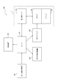
- FIG. 2 is a diagram showing an example of a system 400 in a medical institution including the medical pump system 1 of FIG.
- the medical institution system 400 includes a medical pump system 1, a server 410, a first information processing device 420, a second information processing device 430, and an RF tag writer 440.
- the institutional system 400 may further include a monitoring device 450.
- the components included in the medical institution system 400 are not limited to these, and various devices can be connected.
- the server 410 is a device that manages prescription information associated with each patient.
- Prescription information includes information regarding the administration of the drug to the patient.
- the prescription information may include information for identifying a patient (hereinafter referred to as "patient identification information"), drug identification information, drug dose, administration rate, administration time, and the like.
- patient identification information information for identifying a patient
- the server 410 issues a unique code for each prescription information, and manages the unique code in association with the prescription information.
- the unique code can be a unique number at the medical institution.
- the server 410 may also store the drug library as described above.
- the medical pump 100 can be configured so that necessary information can be appropriately acquired from the server 410.
- the medical pump system 1 may include a server 410 in addition to the medical pump 100, syringe 200 and RF tag 300.
- the server 410 can receive operation information from the medical pump 100 while the medical pump 100 is operating.
- the operation information is information including states such as operation start, operation end, normal operation, administration rate, amount of administered drug, and abnormal occurrence of the medical pump 100.
- the server 410 can display the operation information on the monitoring device 450.
- the first information processing device 420 is a device for inputting prescription information by a doctor and a nurse or the like who has been instructed by the doctor.
- the first information processing device 420 is, for example, an information processing terminal such as a personal computer used by each doctor.
- One unique code is issued and associated with the set of prescription information input from the first information processing device 420 on the server 410.
- the second information processing device 430 is a device that instructs and manages drug dispensing and dispensing based on prescription information.
- a medical worker such as a pharmacist dispenses and dispenses a drug in accordance with the instructions of the second information processing device 430.
- the drug may be dispensed in a pre-filled state such as a prefilled syringe, or the drug may be dispensed in a medical institution according to prescription information and filled in a container.
- the prefilled syringe may be previously equipped with a first RF tag 301 including a standard code which is the first type of identification information for physical distribution management.
- the first type of identification information is unique identification information assigned to the drug as an article.
- the RF tag writer 440 is a device that issues the second RF tag 302 in conjunction with the second information processing device 430.
- the RF tag writer 440 can write data to the memory 330 described later of the second RF tag 302 before writing the data prepared in advance.
- the RF tag writer 440 writes, for example, a unique code which is the second type of identification information on the second RF tag 302.
- the unique code is, for example, a prescription ID.
- the second RF tag 302 issued by the RF tag writer 440 is attached to a syringe 200 including a prefilled syringe and a drug storage container for containing a drug such as an infusion container.
- the second RF tag 302 issued by the RF tag writer 440 may be a sticky sticker on one side.
- the second RF tag 302 can be attached to the syringe 200 by attaching the adhesive seal surface to the syringe 200.
- the monitoring device 450 is a device that is located at a position different from that of the medical pump 100 and displays the operating state of the medical pump 100.
- the monitoring device 450 may be arranged at a nurse station or the like where a nurse is resident. A nurse or the like can monitor the operating state of the medical pump 100 by the monitoring device 450.
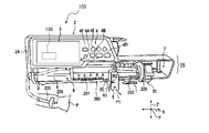
- FIG. 3 is an overview perspective view of the medical pump 100 according to the embodiment of the present disclosure.
- FIG. 4 is an overview front view of the medical pump 100 according to the embodiment of the present disclosure. 3 and 4 show a case where the medical pump 100 is a syringe pump as an example.
- the medical pump 100 is an intravenous anesthetic filled in a syringe 200 in, for example, an operating room and an intensive care unit such as an ICU (Intensive Care Unit), a CCU (Coronary Care Unit), and an NICU (Neonatal Intensive Care Unit). And various drugs including vasoactive drugs are used to continuously deliver liquid into the patient's body.
- Intravenous anesthetics include agents that act on the nervous system to exert a sedative and / or analgesic effect.
- the medical pump 100 can deliver various drugs including an intravenous anesthetic and a vasoactive drug filled in a syringe 200 into the patient's body.
- intravenous anesthetics include propofol, mitazolam, and remifentanil.
- vasoactive agents include epinephrine, noradrenaline, dobutamine, dopamine, isosorbide dinitrate, nitroglycerin and the like.
- the medical pump 100 presses the syringe pusher 202 of the syringe 200 as the drug storage container filled with the drug in the T direction to push the drug in the syringe body 201 into a tube. Accurately deliver fluid to patient P via 203 and indwelling needle 204. At this time, the syringe body 201 of the syringe 200 is set by the clamp 5 so as not to move with respect to the medical pump 100.
- the medical pump 100 has a main body cover 2.
- the main body cover 2 is integrally molded with a molded resin material having chemical resistance. As a result, the main body cover 2 has a splash-proof treatment structure.
- the splash-proof treatment structure can prevent the drug or the like from invading the inside of the medical pump 100 even if the medical pump 100 is exposed to the drug or the like.
- the splash-proof structure is such that the drug in the syringe body 201 spills, the drip solution arranged above the medical pump 100 spills, and the disinfectant solution used in the surrounding area scatters. This is because it may adhere.
- the main body cover 2 has an upper portion 2A and a lower portion 2B.
- a display unit 3 and an operation panel unit 4 are arranged in the upper portion 2A.
- a syringe installation unit 6 and a syringe pusher drive unit 7 for pushing the syringe pusher 202 are arranged in the lower portion 2B.
- the display unit 3 is an image display device capable of displaying in color.
- the display unit 3 can be configured by, for example, a color liquid crystal display device.
- the display unit 3 can display not only information notation in Japanese but also information in a plurality of foreign languages as needed.
- the display unit 3 is located at the upper left position of the upper portion 2A of the main body cover 2, and is arranged above the syringe installation portion 6 and the syringe pusher drive portion 7.
- the display unit 3 may include an input device such as a touch sensor and may accept input from the user.
- the operation panel unit 4 is arranged on the right side of the display unit 3 in the upper portion 2A of the main body cover 2.
- a power ON / OFF button 4A, an operation indicator 4F, and an operation button are arranged on the operation panel unit 4.
- 3 and 4 show an example in which a fast-forward switch button 4B, a start switch button 4C, a stop switch button 4D, and a menu selection button 4E are arranged as operation buttons.
- the syringe installation unit 6 and the syringe pusher drive unit 7 are arranged side by side in the X direction.
- the syringe installation portion 6 can be fitted and fixed to the syringe 200 in a detachable manner.
- the syringe installation unit 6 can fix a plurality of types of syringes 200 having different sizes.
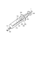
- FIG. 5 shows an external perspective view of the syringe 200.
- the syringe 200 has a syringe body 201 and a syringe pusher 202.
- the syringe body 201 has a body flange 209.
- the syringe pusher 202 has a pusher flange 205.
- a drug scale 210 is formed on the syringe body 201.
- One end of the flexible tube 203 is detachably connected to the outlet portion 211 of the syringe body 201.
- the syringe 200 is a prefilled syringe in which a drug is pre-filled in the syringe body 201
- the syringe 200 is medically provided with a cap for sealing the opening of the outlet 211 attached to the outlet 211 of the syringe body 201.
- Drugs pre-filled in the syringe body 201 include intravenous anesthetics such as propofol, mitazolam, and remifentanil, as well as vasoactive agents such as epinephrine, noradrenaline, dobutamine, dopamine, isosorbide dinitrate, and nitroglycerin. ..
- the syringe 200 is a prefilled syringe.
- the syringe 200 is provided to a medical institution in a state in which a first RF tag 301 storing identification information including drug identification information corresponding to a drug filled in the syringe body 201 is attached to the syringe body 201 in advance.
- a second RF tag 302 that stores a unique code corresponding to prescription information input by a doctor can be further attached to a syringe 200 to which the first RF tag 301 is attached.
- FIG. 6 shows a schematic configuration diagram of the RF tag 300.
- the RF tag 300 includes a communication unit 310, a control circuit 320, and a memory 330.
- the communication unit 310 wirelessly communicates with the reader 170 (see FIG. 9) included in the medical pump 100.
- the communication unit 310 communicates with the reader 170 by short-range wireless communication using, for example, a frequency in the UHF (Ultra High Frequency) band or the HF (High Frequency) band.
- UHF Ultra High Frequency
- HF High Frequency
- the control circuit 320 controls the entire RF tag 300.
- the control circuit 320 returns the identification information stored in the memory 330.
- the memory 330 is a storage device that stores identification information.
- the memory 330 may be mounted on the same IC chip as the control circuit 320.
- the memory 330 may include a non-rewritable area and a rewritable area.
- the identification information can be stored in a rewritable area.
- the memory 330 may include first-class identification information (standard code) uniquely set for articles such as drugs according to the standard.
- the RF tag 300 is the second RF tag 302
- the memory 330 may include a second type of identification information (unique code) uniquely set by the medical institution.
- the memory 330 may store information other than the identification information.
- control circuit 320 when the control circuit 320 receives the identification information transmission request from the medical pump 100 via the communication unit 310, the control circuit 320 transmits the identification information stored in the memory 330 to the medical pump 100.
- the first RF tag 301 can adopt the identification code defined in the ISO / IEC 15459 standard as the identification information.
- ISO / IEC 15459 includes an identification code between ISO format and GS1 format.
- the memory 330 stores information called EPC (Electronic Product Code).
- EPC Electronic Product Code
- the standard to which the first RF tag 301 conforms is not limited to the above.
- the first RF tag 301 may employ RF tags that follow various standards.
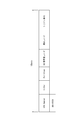
- FIG. 7 is a diagram showing an example of the data structure of SGTIN, which is a standard code according to the GS1 EPC / RFID standard. SGTIN is used as identification information used to identify individual products such as consumer goods and pharmaceuticals.
- EPC Header is an 8-bit area representing the type of EPC standard code. In the case of SGTIN, the EPC Header is 00110000. In addition to SGTIN, various standard codes such as SSCC (Serial Shipping Container Code) and GRAI (Global Returnable Asset Identifier) exist in the EPC standard code. The value of the bit string of "EPC Header” differs depending on each standard code.
- the "GS1 business operator code” is an area in which a code indicating a business operator is stored. The GS1 operator code can be obtained from the Distribution Systems Research Institute in Japan.
- the "product code” is an area in which a code indicating a product is stored.
- the product identification code (GTIN: Global Trade Item Number) of the prefilled syringe is stored by the "GS1 business code” and the “product code”. Therefore, the "GS1 business operator code” and the “product code” are drug identification information capable of identifying the drug.
- the second RF tag 302 can use the same RF tag as the first RF tag 301 except for the information stored in the memory 330.
- FIG. 8 is a diagram showing an example of a data structure of a unique code which is the second type of identification information stored in the second RF tag 302.
- the second type of identification information has a different data structure from the first type of identification information.
- a bit string other than the bit string representing the type of the EPC standard code is arranged in the “EPC Header” area. For example, by setting the first bit of "EPC Header” to 1, a difference from the standard code "EPC Header" can be provided.
- the area following the "EPC Header" area of the memory 330 can be an area for storing the original code.
- the area in which the unique code of FIG. 8 is stored can further have a unique data structure.
- the medical pump 100 can refer to the identification information "EPC Header" received from the RF tag 300 and determine whether the identification information is a standard code or a medical institution's own code.
- the device configuration of the medical pump 100 will be described again with reference to FIGS. 3 and 4.
- the syringe installation unit 6 has an accommodating unit 8 for accommodating the syringe body 201 and a clamp 5.
- the accommodating portion 8 is a recess having a substantially semicircular cross section for accommodating the syringe body 201, and is formed along the X direction.
- a tube fixing portion 9 for detachably sandwiching the tube 203 is formed on the wall portion at the end of the accommodating portion 8.
- the clamp 5 When the clamp 5 is operated to remove the syringe 200 from the syringe installation portion 6, the clamp 5 is pulled in the Y1 direction (frontward direction) against the force of a spring (not shown), and further turned 90 degrees in the R1 direction. By this operation, the fixation of the syringe body 201 by the clamp 5 is released, and the syringe 200 can be removed from the accommodating portion 8. Further, when the clamp 5 is operated to attach the syringe 200 to the syringe installation portion 6, the clamp 5 is pulled in the Y1 direction against the force of a spring (not shown) and turned 90 degrees in the R2 direction by the force of the spring. Return to the Y2 direction.
- the syringe body 201 can be accommodated in the accommodating portion 8 and fixed by the clamp 5.
- a part of the right end 8E of the accommodation part 8 of the syringe installation part 6 is a notch so that the clamp 5 can fix the syringe 200 having various capacitys such as 5mL, 10mL, 20mL, 30mL, and 50mL. It has become.
- the syringe pusher 202 When the syringe body 201 is accommodated and fixed in the accommodating portion 8, the syringe pusher 202 is arranged in the syringe pusher drive portion 7.
- the syringe pusher drive unit 7 has a slider 10. The slider 10 pushes the pusher flange 205 of the syringe pusher 202 little by little along the T direction relative to the syringe body 201 in response to a command from the control unit 180 shown in FIG.
- the X, Y, and Z directions in FIGS. 3 and 4 are orthogonal to each other.
- the Z direction is the vertical direction.
- the medical pump 100 has a control unit (computer) 180 that determines and controls the overall operation.
- the control unit 180 is, for example, a one-chip microcomputer.
- control unit 180 the power ON / OFF button 4A and the switch 111 are connected.
- the switch 111 supplies power to the control unit 180 from either the power converter unit 112 or the rechargeable battery 113 by switching between the power converter unit (power supply unit) 112 and the rechargeable battery 113 such as a lithium ion battery. To do.
- the power converter unit 112 is connected to the commercial AC power supply 115 via the outlet 114.
- the pump unit 160 is electrically connected to the control unit 180.
- the pump unit 160 administers the drug to the patient according to the information regarding the administration of the drug according to the command from the control unit 180.
- Information regarding the administration of a drug includes at least one or more of a drug dose, a rate of administration, an administration time, an upper limit value and a lower limit value of the administration rate.
- the information regarding the administration of the drug is set based on at least one of the prescription information obtained from the server 410 and the drug profile of the drug library stored in the server 410 or the storage unit 110.
- a pair of detection switches 120 and 121 are arranged in the accommodating portion 8 of the pump portion 160.
- the detection switches 120 and 121 detect whether or not the syringe body 201 of the syringe 200 is correctly arranged in the accommodating unit 8 and notify the control unit 180.
- the clamp sensor 122 of the pump unit 160 detects the position state of the clamp 5 to notify the control unit 180 whether or not the syringe body 201 is securely clamped by the clamp 5.
- the feed screw 135 is rotated to move the slider 10 in the T direction.
- the slider 10 presses the pusher flange 205 of the syringe pusher 202 in the T direction, and the drug in the syringe body 201 shown in FIG. 4 is passed through the tube 203 to the patient P via the indwelling needle 204. Send the liquid accurately.
- the fast forward switch button 4B, the start switch button 4C, the stop switch button 4D, and the menu selection button 4E are electrically connected to the control unit 180.
- the start switch button 4C is pressed, a control signal for starting liquid feeding is input to the control unit 180.
- the stop switch button 4D is pressed, a control signal for stopping the liquid feeding is input to the control unit 180.
- the display unit driver 130 is electrically connected to the control unit 180.
- the display unit driver 130 drives the display unit 3 in response to a command from the control unit 180 to display various information on the display unit 3.
- the notification unit 131 is electrically connected to the control unit 180.
- the notification unit 131 notifies various alarm contents by voice, light, vibration, or the like according to the command of the control unit 180. Further, when the control unit 180 notifies various alarm contents by displaying on the display unit 3, the display unit 3 may have a function as a notification unit.
- the communication unit 140 may include at least one of a wireless communication means and a wired communication means.
- the communication unit 140 may be connected to a network such as a LAN (Local Area Network) in the medical institution.
- the communication unit 140 communicates with the server 410 of the medical institution via the network.
- the control unit 180 may acquire prescription information, a drug library, and the like from the server 410 via the communication unit 140.
- the communication unit 140 may transmit / receive data to / from the monitoring device 450 via the network.
- the control unit 180 may notify the monitoring device 450 of the abnormality via the communication unit 140.
- the communication unit 140 may transmit / receive data by locally connecting to a computer such as a desktop computer.
- the reader 170 communicates with the communication unit 310 of the RF tag 300 attached to the syringe 200 by wireless communication.
- the reader 170 can communicate with a plurality of RF tags 300.
- the reader 170 transmits a request for transmitting identification information to the RF tag 300.
- the reader 170 acquires the identification information transmitted from the RF tag 300 in response to the transmission request from the reader 170.
- the syringe 200 has a first RF tag 301 and a second RF tag 302
- the reader 170 acquires identification information from each of the first RF tag 301 and the second RF tag 302.
- control unit 180 Based on the data in the predetermined area of the identification information acquired by the reader 170, the control unit 180 is either the first type of identification information uniquely defined according to the standard, or is independently set by the medical institution. Determine if it is the second type of identification information.
- the storage unit 110 may be configured by using, for example, a semiconductor memory, a magnetic memory, or the like.
- the storage unit 110 stores various information and programs necessary for the operation of the medical pump 100.
- the storage unit 110 may store a drug library containing a plurality of drug profiles.
- the storage unit 110 can store a drug library customized by the medical institution that owns the medical pump 100.
- the control unit 180 downloads the drug library stored in the server 410 of the medical institution to the storage unit 110 via the communication unit 140, so that the storage unit 110 downloads the drug library customized by the medical institution. Can be remembered.
- the control unit 180 identifies the drug from the standard code included in the identification information.
- the first type of identification information is a GSTIN standard code according to the SG1 EPC / RFID standard shown in FIG. 7, the control unit 180 uses the “GS1 operator code” and the “product code” as drug identification information for the drug. Can be identified.
- control unit 180 When the control unit 180 acquires only the first type of identification information, the control unit 180 can execute the following processing.
- the control unit 180 determines whether or not the drug profile corresponding to the acquired drug specific information is stored in the storage unit 110, and if it is stored, reads the information of the drug profile.
- the drug profile includes a reference administration rate, an upper limit value / a lower limit value of the administration rate, and the like.
- the control unit 180 can display the reference administration rate on the display unit 3 as the initial setting value of the administration rate.
- the control unit 180 warns by the notification unit 131. It can be notified.
- the display unit 3 functions as a notification unit, the control unit 180 may notify the warning by changing the display of the display unit 3.
- the control unit 180 notifies the notification unit 131 of a warning. ..
- the medical pump 100 can thereby prevent the user from administering the drug at a dosing rate greater than or less than the lower limit of the dosing rate specified in the drug profile.
- control unit 180 may execute the following processing. it can.
- the control unit 180 acquires the prescription information associated with the original code from the server 410 based on the original code included in the acquired second type identification information.
- the prescription information includes information such as patient-specific information, drug-specific information, drug dose, administration rate, and administration time.
- the control unit 180 can display the patient name on the display unit 3 based on the patient identification information.
- the control unit 180 can display set values such as the dose, administration rate, and administration time of the drug included in the prescription information on the display unit 3. These set values can be set as information regarding the administration of the drug as they are after confirmation by the user. As a result, the medical pump 100 can reduce the possibility that the user erroneously sets the set value related to the administration of the drug.
- the control unit 180 determines whether or not the drug profile corresponding to the drug specific information is stored in the storage unit 110, as in the case where only the first type of identification information is acquired, and if it is stored, the control unit 180 determines whether or not the drug profile corresponding to the drug specific information is stored in the storage unit 110.
- the drug profile information may be read. If it is not stored, it may be obtained from the drug library stored in the server 410. Similar to the case where only the identification information of the first type is acquired, the control unit 180 uses the notification unit 131 when the administration rate of the drug exceeds the upper limit value or the lower limit value of the administration rate specified in the drug profile. A warning can be sent.
- the control unit 180 When only the first type of identification information is acquired, the control unit 180 performs processing based only on the drug-specific information specified only by the drug-specific information. On the other hand, when the second type of identification information is acquired, the control unit 180 is different in that it executes a process that reflects the prescription information for the individual patient. Further, as compared with the case where only the first type of identification information is acquired, when the second type of identification information is acquired, more information can be associated with the drug filled in the syringe 200. different.
- the control unit 180 Based on the identification information of the RF tag 300 attached to the syringe 200 attached to the medical pump 100, the control unit 180 sets a part or all of the drug identification information, the drug profile, and the prescription information as information on administration. To get.
- the control unit 18 can reflect at least a part of the information regarding administration in the display content of the display unit 3.
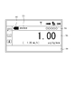
- FIG. 10 shows an example of the display of the display unit 3.
- the drug name display field 701, the drug color display field 702, and the administration setting display field 703 are displayed. If there is a message, the message is displayed in the message field 704. Further, when the patient name can be obtained, the patient name display field 705 is displayed.
- a drug name such as "nitroglycerin” is displayed.
- a preset color corresponding to the drug is displayed.
- the administration rate and the flow rate are displayed.
- 1.00 [ ⁇ g / kg / min] is displayed as the administration rate
- 1.20 [mL / h] is displayed as the flow rate.
- the control unit 180 acquires the prescription information
- the patient name is displayed based on the patient identification information included in the prescription information.
- control unit 180 controls the pump unit 160 so that the drug is administered to the patient according to the set information regarding the administration of the drug.
- FIGS. 2 and 11 For a procedure for mounting the second RF tag 302 including the second type of identification information in the hospital system 400, which is a premise for the explanation of the operation of the medical pump system 1, on the syringe 200. I will explain.
- the doctor who examined the patient inputs the prescription information via the first information processing device 420 (step S101).
- the doctor inputs the patient identification information, the drug identification information such as the drug name, the dose of the drug, the administration rate, the administration time, and the like into the first information processing device 420.
- the prescription information entered by the doctor is transmitted to the server 410.
- the server 410 that has received the prescription information from the first information processing device 420 issues the second type of identification information and manages the received prescription information (step S102).
- the second type of identification information is, for example, a unique code such as a prescription ID represented by a unique number in a medical institution.
- the prescription information is associated with the second type of identification information and is managed in the server 410.
- the prescription information is transmitted to the second information processing device 430 after undergoing a prescription audit as necessary.
- the second information processing device 430 is located, for example, in the pharmaceutical department in a medical institution.
- the pharmacist in the pharmaceutical department dispenses and / or dispenses the drug based on the prescription information presented to the second information processing device 430 (step S103).
- the drug may be used as it is filled in a container such as a prefilled syringe, or may be dispensed in a medical institution and filled in the syringe 200.
- the prefilled syringe may be equipped with a first RF tag 301 previously attached by a drug manufacturer.
- the RF tag writer 440 issues a second RF tag 302 having the second type of identification information (step S104).
- the issuance of the second RF tag 302 is executed by the RF tag writer 440 writing the second type of identification information to the memory 330 of the second RF tag 302 prepared in advance.
- the process of step S104 may be performed before the process of step S103. Alternatively, the process of step S104 may be performed in parallel with the process of step S103.
- the second RF tag 302 issued in step S104 is attached to the syringe 200 including the prefilled syringe discharged in step S103 or the syringe filled with the dispensed drug (step S105).
- both the first RF tag 301 and the second RF tag 302, or only the second RF tag 302 are attached to the surface of the syringe 200.
- the second RF tag 302 in step S104 is not issued and the second RF tag 302 is not attached to the container in step S105. Therefore, only the first RF tag 301 may be attached to some syringes 200.
- a user such as a nurse attaches a syringe 200, which is a drug storage container, to the medical pump 100 (step S201).
- the reader 170 of the medical pump 100 reads the identification information from the RF tag 300 attached to the syringe 200 (step S202). When a plurality of RF tags 300 are attached to the medical pump 100, the reader 170 reads the plurality of identification information.
- the control unit 180 of the medical pump 100 performs the subsequent processing according to the number of identification information read by the reader 170 (step S203).
- the number of identification information read by the reader 170 is the same as the number of RF tags with which the reader 170 communicated.
- step S203 when the number of identification information read by the reader 170 is only one, the control unit 180 uses the one identification information to set the information regarding the administration of the drug in the medical pump 100. Is selected as (step S204).
- the selected identification information may be the first identification information acquired by the reader 170 from the first RF tag 301 or the second identification information acquired by the reader 170 from the second RF tag 302.
- step S203 when the number of identification information read by the reader 170 is two, the control unit 180 determines whether or not the two identification information are the same (step S205).
- the first identification information is a code uniquely given to the drug based on the standard.
- the second identification information is a code that is assigned without duplication within the medical institution. Therefore, when the two identification information is the same (step S205: Yes), it means that some abnormality has occurred. For example, it is assumed that there is an error in which the same code is assigned to different RF tags 300.
- step S205: No the control unit 180 proceeds to the next step S206.
- step S206 the control unit 180 determines whether the two identification information read by the reader 170 includes one of the second type of identification information.
- one of the two identification information is not the second type of identification information (step S206: No)
- the syringe 200 is equipped with only the first RF tag 301, but when the reader 170 reads the identification information, it seems that the identification information of the RF tag 300 of another syringe 200 located close to the syringe 200 is read. A case is assumed.
- both of the two identification information are the second type of identification information, it is considered that it is due to some abnormality.
- the control unit 180 proceeds to the next step S207.
- step S207 the control unit 180 selects the second type of identification information as the identification information used to set the information regarding the administration of the drug to the medical pump 100 (step S207).
- step S203 when the number of identification information read by the reader 170 is three or more, the control unit 180 suspends the selection of the identification information (step S208). That is, the control unit 180 leaves the determination of selection of the identification information undecided and does not set the information regarding the administration of the drug. Since a maximum of two RF tags 300 are attached to the syringe 200, it is determined that the reader 170 reads three or more identification information due to some error. For example, it is assumed that the cause of this occurrence is that the reader 170 mistakenly reads the RF tags of other syringes located in close proximity to the syringe 200 mounted on the medical pump 100. Will be done.
- step S205 Yes
- step S206 No
- the control unit 180 also performs.
- the selection of the identification information is suspended (step S208), and the information regarding the administration of the drug based on the identification information is not set.
- control unit 180 After step S208, the control unit 180 returns to step S202 and continues the process.
- the control unit 180 repeats reading the identification information from the RF tag 300 until the RF tag 300 attached to the syringe 200 can be read normally.
- the control unit 180 sets the information regarding the administration of the drug to the medical pump 100 based on the identification information (step). S209).
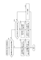
- the process of setting the information regarding the administration of the drug based on the identification information will be described with reference to the flowchart of FIG.
- control unit 180 determines whether or not the identification information is the second type of identification information (step S301).
- the control unit 180 reads the prescription information stored in association with the second type of identification information from the server 410 (step S302).
- the read prescription information can be stored in the storage unit 110.
- the control unit 180 may acquire the drug profile corresponding to the drug identification information from the drug library of the server 410 based on the drug identification information included in the prescription information together with the prescription information.
- the control unit 180 sets the information regarding the administration of the drug according to the read prescription information (step S303). Specifically, the control unit 180 sets information such as the patient name, drug identification information, drug dose, administration rate, and administration time defined in the prescription information as information related to drug administration. In addition, the information regarding the administration of the set drug may include information included in the drug profile of the drug specified by the drug specific information.
- the control unit 180 determines whether or not the identification information is the first type of identification information (step S304).
- step S304 When the identification information is the first type of identification information (step S304: Yes), the control unit 180 acquires a drug profile corresponding to the drug identification information included in the identification information from the storage unit 110 or the server 410 in the medical institution. (Step S305).
- the control unit 180 sets the information regarding the administration of the drug according to the acquired drug profile (step S306). Specifically, the control unit 180 can display the reference administration rate defined in the drug profile on the display unit 3 as the initial setting value of the administration rate. When the administration rate exceeding the upper limit value specified in the drug profile or the administration rate lower than the lower limit value is set, the control unit 180 can issue an alarm by the notification unit 131.
- step S304 When it is determined in step S304 that the identification information is not the first type of identification information (step S304: No), the control unit 180 notifies the error by the notification unit 131 (step S307). The control unit 180 may return to the process of step S202 instead of notifying the error.
- the control unit 180 selects only one identification information. Therefore, even when the two RF tags 300 are attached to the syringe 200, the information regarding the administration of the drug can be appropriately set in the medical pump 100.
- the reader 170 refers to the data in a predetermined area of the information acquired from the RF tag 300, and refers to the identification information and the prescription information of the first type assigned to the drug. It is possible to easily distinguish it from the second type of identification information associated with. Therefore, the control unit 180 of the medical pump 100 can perform processing according to the type of identification information.
- the medical pump system 1 of the present disclosure when reading the identification information of the RF tag 300 attached to the syringe 200, when the same identification information is read more than once, or when three or more identification informations are read. , Recognize as an error and do not set information on drug administration. This makes it possible to reduce the risk of erroneous administration of the drug in a situation suspected of being an error.
- the medical pump system 1 of the present disclosure includes a case where a first RF tag 301 having the first type of identification information is attached to a prefilled syringe or the like in advance, and a second RF tag having the second type of identification information uniquely in a medical institution. It is possible to deal with both the case where 302 is attached. Further, since the control unit 180 of the medical pump 100 preferentially adopts the second type of identification information over the first type of identification information, the prescription information is associated with the patient's prescription information and has a larger amount of information. Can be set as information regarding the administration of the drug.
- the medical pump system 1 of the present disclosure is configured so that prescription information can be acquired from the server 410 via the communication unit 140, so that it can be linked with the prescription information created by a doctor and is a medical pump.
- the capacity of the storage unit 132 of 100 can be reduced.
- the medical pump 100 reads the identification information of the second type of the second RF tag 302 attached to the syringe 200.
- the medical pump 100 acquires prescription information associated with the second type of identification information from the server 410, and sets a part or all of the prescription information in the medical pump 100 as information regarding the administration of the drug.
- Information regarding the administration of the drug set in the medical pump 100 is displayed, at least in part, on the display unit 3 of the medical pump 100.
- the doctor or nurse who administers the drug by the medical pump 100 can confirm information such as the name of the patient who is trying to administer the drug and the drug.
- a doctor or a nurse can confirm that the personally identifiable information such as a medical examination ticket held by a patient who is trying to administer a drug matches the name of the patient displayed on the display unit 3.
- a doctor or a nurse possesses an information terminal and can confirm that the prescription information read from the server 410 and the information displayed on the display unit 3 of the medical pump 100 are consistent. ..
- the reader 170 of the medical pump 100 reads the second type identification information of the second RF tag 302, acquires the prescription information from the server 410, and sets them in the medical pump 100, the medical pump 100 initially sets them. It can be configured to be set as a value. As a result, it is possible to suppress the occurrence of errors such as a doctor or a nurse misreading the prescription information and making a mistake in the dose or administration rate of the drug.
- the medical pump is not limited to a syringe pump, and may be another type of medical pump such as an infusion pump that delivers a drug contained in an infusion bag. If the medical pump is an infusion pump, the infusion bag is the drug compartment.
- This disclosure relates to medical pumps, control methods for medical pumps, and medical pump systems.
Abstract
医療用ポンプは、RFタグに記憶された識別情報を無線通信により読み取り可能なリーダと、前記RFタグから読み取った前記識別情報に基づいて、投与に関する情報を設定する制御部と、を備え、前記リーダが2つの異なる前記識別情報を読み取った場合、前記制御部は、前記2つの異なる前記識別情報のうち1つの識別情報のみを選択して、前記投与に関する情報を設定する。
Description
本開示は、医療用ポンプ、医療用ポンプの制御方法、及び、医療用ポンプシステムに関する。
シリンジポンプ及び輸液ポンプなどの医療用ポンプは、例えば手術室及び集中治療室(ICU)等で使用される。医療用ポンプは、患者に対して抗癌剤、麻酔剤、化学療法剤、及び栄養剤などの薬剤の投与を、高い精度で比較的長時間行う場合などに用いられる。
医療用ポンプで薬剤を投与する際に、誤った設定で薬剤を投与することを抑制するため、薬剤ライブラリを用いる手法が知られている(例えば、特許文献1参照)。薬剤ライブラリは、例えば数千種類の薬剤のそれぞれについて、投与する際の設定情報等をデータベース化したものである。薬剤ライブラリにおいて、各薬剤は、基準投与速度、投与速度の上限値/下限値、薬剤コード、及び薬剤カラーなどの薬剤固有の設定情報を有する。
また、薬剤ライブラリを医療用ポンプに記憶させ、薬剤を充填したシリンジ等に貼り付けたRF(radio frequency)タグを用いて、薬剤固有の設定情報に従い薬剤を投与する方法が提案されている(例えば、引用文献2参照)。この場合、医療用ポンプは、RFタグに記憶された薬剤特定情報を読み出し、当該薬剤特定情報に対応する薬剤固有の設定情報に基づいて、投与速度等の薬剤の投与に関する情報が設定される。薬剤特定情報は、薬剤を特定することができる情報であり、例えば薬剤コードである。
RFタグを使用することによって、病院等の医療機関内において、医療用ポンプに使用するシリンジ容器及び輸液容器等に収容される薬に対応した設定情報の取得を自動化及び迅速化することができる。また、RFタグを使用することによって、人為的な誤りによる薬剤の誤投与を抑制することが期待できる。このため、将来的に、医療用ポンプにおけるRFタグの活用が期待される。
医療用ポンプで使用される薬剤は、シリンジ容器に予め薬剤を充填したプレフィルドシリンジ等として、医薬品メーカーから提供される場合がある。将来的に、プレフィルドシリンジには、物流管理を目的として薬品メーカーの工場内でRFタグが装着されることが想定される。物流管理用のRFタグは、例えば、SGTIN(Serialized Global Trade Item Number)のような、世界的に一意的に個々の物品を識別できる標準コードが採用されるものと考えられる。
一方、医療用ポンプで使用されるシリンジ容器及び輸液容器等には、将来的に、医療機関内での薬剤認証を目的とするRFタグが装着されることが想定される。薬剤認証用のRFタグは、薬剤の誤投与等を抑制することを目的とする。薬剤認証用のRFタグは、患者に対する処方情報と関連付けられた医療機関の独自コードが採用されるものと考えられる。本開示において、RFタグから取得される標準コード及び独自コードは、RFタグが装着されたシリンジ容器及び輸液容器等の薬剤収納容器に充填された薬剤を識別するための情報なので、識別情報と呼ぶ。
しかしながら、1つのシリンジ容器又は輸液容器に、物流管理用のRFタグと薬剤認証用のRFタグとの2つのRFタグが装着されると、医療用ポンプでこれらのRFタグを読み出す際に2つの識別情報が読み出されることがある。2つの識別情報を読み出した場合、医療用ポンプは何れの識別情報に従って、薬剤の投与に関する情報を設定するのか明確化される必要がある。
かかる点に鑑みてなされた本開示の目的は、複数の識別情報を読み取った場合に適切に薬剤を投与することができる医療用ポンプ、医療用ポンプの制御方法、及び医療用ポンプシステムを提供することにある。
本開示の第1態様としての医療用ポンプは、RFタグに記憶された識別情報を無線通信により読み取り可能なリーダと、前記RFタグから読み取った前記識別情報に基づいて、薬剤の投与に関する情報を設定する制御部とを備える。前記リーダが2つの異なる前記識別情報を読み取った場合、前記制御部は、前記2つの異なる前記識別情報のうち1つの識別情報のみを選択して、前記投与に関する情報を設定する。
本開示の1つの実施形態として、前記RFタグは、前記薬剤を収容する薬剤収納容器に装着される。
本開示の1つの実施形態として、前記薬剤収納容器はシリンジである。
本開示の1つの実施形態として、前記リーダが2つの異なる前記識別情報を読み取った場合、前記制御部は、それぞれの前記識別情報に含まれる所定領域のデータに基づいて前記1つの識別情報のみを選択する。
本開示の1つの実施形態として、前記リーダが2つの同じ前記識別情報を読み取った場合、前記制御部は、前記投与に関する情報を設定しない。
本開示の1つの実施形態として、前記リーダが3つ以上の前記識別情報を読み取った場合、前記制御部は、前記投与に関する情報を設定しない。
本開示の1つの実施形態として、前記リーダが1つの前記識別情報のみを読み取った場合、前記制御部は、読み取った前記1つの識別情報に基づいて、前記投与に関する情報を設定する。
本開示の1つの実施形態として、前記医療用ポンプは、前記投与に関する情報を表示する表示部をさらに備える。
本開示の1つの実施形態として、前記識別情報は、データ構造の異なる第1種類の識別情報と第2種類の識別情報とを含む。前記制御部は、前記2つの異なる前記識別情報の一方が前記第1種類の識別情報であり、他方が前記第2種類の識別情報であるとき、前記第2種類の識別情報のみを選択する。
本開示の1つの実施形態として、前記第1種類の識別情報は、前記薬剤に割り当てられた識別情報であり、前記第2種類の識別情報は、前記薬剤を投与する処方情報に関連付けられた識別情報である。
本開示の1つの実施形態として、前記制御部は、前記識別情報が前記第2種類の識別情報を含む場合、前記処方情報の少なくとも一部を前記投与に関する情報として設定する。
本開示の1つの実施形態として、前記医療用ポンプは、サーバと通信する通信部をさらに備え、前記制御部は、前記通信部を介して前記サーバから前記第2種類の前記識別情報に関連付けられて記憶される前記処方情報を取得する。
本開示の1つの実施形態として、前記第1種類の識別情報は、標準に従い一意的に定義された識別情報である。前記第2種類の識別情報は、医療機関により独自に設定された識別情報である。
本開示の第2の態様としての医療用ポンプの制御方法は、RFタグに記憶された識別情報を無線通信により読み取り、前記RFタグから読み取った前記識別情報に基づき、薬剤の投与に関する情報を設定する医療用ポンプの制御方法である。この制御方法は、2つの異なる前記識別情報を読み取った場合、前記2つの異なる前記識別情報のうち、1つの識別情報のみを選択して、前記投与に関する情報を設定する。
本開示の第3の態様としての医療用ポンプシステムは、RFタグが装着された薬剤収納容器と、医療用ポンプとを備える医療用ポンプシステムである。前記薬剤収納容器は、患者に投与する薬剤を収容する。前記医療用ポンプは、前記RFタグに記憶された識別情報を無線通信により読み取り可能なリーダと、前記RFタグから読み取った前記識別情報に基づいて、薬剤の投与に関する情報を設定する制御部とを備える。前記リーダが2つの異なる前記識別情報を読み取った場合、前記制御部は、前記2つの異なる前記識別情報のうち、1つの識別情報のみを選択して、前記投与に関する情報を設定する。
本開示の1つの実施形態として、サーバをさらに備え、前記医療用ポンプはサーバと通信する通信部をさらに備える。前記識別情報は、第1種類の識別情報と第2種類の識別情報とを含む。前記サーバは、前記第2種類の識別情報に関連づけられて記憶される情報を記憶する。前記制御部は、前記2つの異なる前記識別情報の一方が前記第1種類の識別情報であり、他方が前記第2種類の識別情報であるとき、前記第2種類の識別情報のみを選択する。前記制御部は、前記通信部を介して前記サーバから前記第2種類の前記識別情報に関連付けられて記憶される前記情報を取得し、前記投与に関する情報を設定する。
本開示に係る医療用ポンプ、医療用ポンプの制御方法、及び医療用ポンプシステムによれば、複数の識別情報を読み取った場合に、適切に薬剤の投与に関する情報を設定することができる。
以下、図面を参照して、本開示の実施形態を説明する。図面の寸法比率は、説明の都合上、誇張されて実際の比率とは異なる場合がある。また、各図において、共通の部材には同一の符号を付している。
(医療用ポンプシステムを含む医療機関内システムの概略)
図1は、本開示の一実施形態に係る医療用ポンプシステム1の概略構成図である。医療用ポンプシステム1は、医療用ポンプ100と、シリンジ200とを備える。シリンジ200は、医療用ポンプ100に装着可能である。シリンジ200には、1つ以上のRFタグ300が装着されている。図示の例では、1つ以上のRFタグ300は、第1RFタグ301及び第2RFタグ302を含む。
図1は、本開示の一実施形態に係る医療用ポンプシステム1の概略構成図である。医療用ポンプシステム1は、医療用ポンプ100と、シリンジ200とを備える。シリンジ200は、医療用ポンプ100に装着可能である。シリンジ200には、1つ以上のRFタグ300が装着されている。図示の例では、1つ以上のRFタグ300は、第1RFタグ301及び第2RFタグ302を含む。
RFタグ300は、無線により情報を読み出し可能な小型の電子装置である。RFタグ300は、外部から電磁波を受けて、少なくとも識別情報(ID情報)を送信することができる。識別情報は、個々のRFタグ300が装着されたシリンジ200内の薬剤を識別することができる情報である。本願において、RFタグ300は、RFID(radio frequency identifier)、無線タグ及びIC(Integrated Circuit)タグと同義である。医療用ポンプ100と、RFタグ300とは、例えば、UHF(Ultra High Frequency)帯、又は、HF(High Frequency)帯の周波数を用いて無線通信によって通信を行うことができる。例えば、RFタグ300は、ISO/IEC 18000-63規格に準拠するRFタグを採用しうる。RFタグ300は、ISO/IEC 18000-63規格に準拠するRFタグに限られない。
本開示の一実施形態において、第1RFタグ301は、物流管理等に使用される標準コードを採用するRFタグである。本実施形態において、標準コードは第1種類の識別情報である。標準コードは、例えば、SGTINを含む。SGTINは、事業者を特定する事業者コード、商品を特定する商品コード、及び、商品ごとのシリアル番号を含む。したがって、標準コードは薬剤を特定する薬剤特定情報を含む。シリンジ200がプレフィルドシリンジである場合、第1RFタグ301は、プレフィルドシリンジを製造するメーカーの工場等において装着されうる。標準コードは、第1種類の識別情報の一例である。第1種類の識別情報は、標準コードに限られない。
第2RFタグ302は、医療機関内での薬剤認証等を目的として装着される、医療機関独自のコード(独自コード)を採用したRFタグとしうる。本実施形態において、医療機関の独自コードは第2種類の識別情報である。独自コードとしては、医療機関内での患者への処方ID、又は、処方IDと関係付けられたコードを使用しうる。ここで、処方IDとは、医師による患者への薬剤の投与方法の指示である処方情報に割り当てられる識別情報である。第2RFタグ302は、医療機関内において薬剤を払出又は調剤するときに発行され、シリンジ200等の薬剤の容器に装着されうる。医療機関の独自コードは、第2種類の識別情報の一例である。第2種類の識別情報は、医療機関の独自コードに限られない。
医療用ポンプ100がRFタグ300に送信する電磁波の強度は、所定の強度以下に制限される。所定の強度は、シリンジ200が医療用ポンプ100に装着されているときはRFタグ300が受信可能であるが、シリンジ200が医療用ポンプ100から所定の距離以上離れているときは、RFタグ300が受信することができない程度の強度である。これにより、医療用ポンプ100が、医療用ポンプ100に装着されていないシリンジ200に貼り付けられたRFタグ300から誤ってデータを読み取ることを抑制することができる。
医療用ポンプ100は、薬剤ライブラリを記憶してよい。薬剤ライブラリは、例えば数千種類の薬剤のそれぞれについて、投与する際の薬剤固有の設定情報等をデータベース化したものである。薬剤ライブラリにおいて、各薬剤は、基準投与速度、投与速度の上限値/下限値、薬剤コード、及び薬剤カラーなどの設定情報を有する。以後、一つの薬剤についての複数の設定情報の集まりを「薬剤プロファイル」とも称する。薬剤ライブラリは、医療用ポンプ100ではなく後述する医療機関内のサーバ410に記憶されてもよい。その場合、医療用ポンプ100は、サーバ410に記憶される薬剤ライブラリから必要な設定情報を適宜取得するように構成されもよい。
図2は、図1の医療用ポンプシステム1を含む医療機関内システム400の一例を示す図である。医療機関内システム400は、医療用ポンプシステム1、サーバ410、第1情報処理装置420、第2情報処理装置430、RFタグライタ440を含む。医療機関内システム400は、さらに監視装置450を含んでよい。医療機関内システム400に含まれる構成要素はこれらに限られず、種々の装置が接続可能である。
サーバ410は、各患者に関連付けられた処方情報を管理する装置である。処方情報は、患者に対する薬剤の投与に関する情報を含む。処方情報は、患者を特定する情報(以下、「患者特定情報」とよぶ)、薬剤特定情報、薬剤の投与量、投与速度、投与時間等の情報を含んでよい。サーバ410は、各処方情報に対して独自コードを発行し、この独自コードと処方情報とを関連付けて管理する。独自コードは、医療機関において重複のない番号としうる。また、サーバ410は、上述のように薬剤ライブラリを記憶してよい。医療用ポンプ100は、適宜必要な情報をサーバ410から取得可能に構成しうる。医療用ポンプシステム1は、医療用ポンプ100、シリンジ200及びRFタグ300に加え、サーバ410を含んでもよい。
サーバ410は、医療用ポンプ100の動作中に、医療用ポンプ100から動作情報を受信することができる。動作情報は、医療用ポンプ100の動作開始、動作終了、正常動作中、投与速度、投与済みの薬剤の量、異常発生等の状態を含む情報である。サーバ410は、動作情報を監視装置450に表示させることができる。
第1情報処理装置420は、医師及び医師から指示を受けた看護師等が処方情報を入力する装置である。第1情報処理装置420は、例えば、各医師が使用するパーソナルコンピュータ等の情報処理端末である。第1情報処理装置420から入力される一組の処方情報に対して、サーバ410において1つの独自コードが発行され関連づけられる。
第2情報処理装置430は、処方情報に基づいて、薬剤の払出及び調剤を指示、管理する装置である。薬剤師等の医療関係従事者は、第2情報処理装置430の指示に従って、薬剤の払出及び調剤を行う。薬剤は、プレフィルドシリンジのように、予め薬剤が充填された状態で払出される場合と、処方情報に従い医療機関内で薬剤を調剤して容器に充填する場合とがある。プレフィルドシリンジには、予め物流管理のために第1種類の識別情報である標準コードを含む第1RFタグ301が装着されていることがある。第1種類の識別情報は、物品としての薬剤に割り当てられた固有の識別情報である。
RFタグライタ440は、第2情報処理装置430と連動して第2RFタグ302を発行する装置である。RFタグライタ440は、予め用意されたデータを書き込む前の第2RFタグ302の後述するメモリ330に、データを書き込むことができる。RFタグライタ440は、第2RFタグ302に、例えば、第2種類の識別情報である独自コードを書き込む。独自コードは、例えば処方IDである。RFタグライタ440により発行された第2RFタグ302は、プレフィルドシリンジを含むシリンジ200、及び、輸液容器等の薬剤を収容する薬剤収納容器に装着される。RFタグライタ440の発行する第2RFタグ302は、一方の面が粘着性のシールであってよい。第2RFタグ302は、粘着性のシールの面をシリンジ200に貼り付けることにより、シリンジ200に装着することができる。
監視装置450は、医療用ポンプ100とは異なる位置に位置して医療用ポンプ100の動作状態を表示する装置である。例えば、監視装置450は、看護師が常駐しているナースステーション等に配置されてよい。看護師等は、監視装置450により、医療用ポンプ100の動作状態を監視することができる。
(医療用ポンプシステムの構成)
次に、医療用ポンプシステム1の各構成要素について詳細に説明する。図3は、本開示の一実施形態に係る医療用ポンプ100の概観斜視図である。図4は、本開示の一実施形態に係る医療用ポンプ100の概観正面図である。図3及び図4においては、一例として、医療用ポンプ100がシリンジポンプである場合を示している。
次に、医療用ポンプシステム1の各構成要素について詳細に説明する。図3は、本開示の一実施形態に係る医療用ポンプ100の概観斜視図である。図4は、本開示の一実施形態に係る医療用ポンプ100の概観正面図である。図3及び図4においては、一例として、医療用ポンプ100がシリンジポンプである場合を示している。
医療用ポンプ100は、例えば、手術室並びにICU(Intensive Care Unit)、CCU(Coronary Care Unit)、及びNICU(Neonatal Intensive Care Unit)等の集中治療室等において、シリンジ200に充填された静脈麻酔薬及び血管作動薬等を含む種々の薬剤を持続的に患者の体内に送液するために使用される。静脈麻酔薬は、神経系に作用して鎮静効果及び/又は鎮痛効果を発揮する薬剤を含む。
医療用ポンプ100は、シリンジ200に充填された静脈麻酔薬及び血管作動薬等を含む種々の薬剤を患者の体内に送液することができる。適用可能な静脈麻酔薬の例として、プロポフォール、ミタゾラム、及びレミフェンタニル等がある。適用可能な血管作動薬の例として、エピネフリン、ノルアドレナリン、ドブタミン、ドパミン、硝酸イソソルビド、及びニトログリセリン等がある。
図3及び図4に示すように、医療用ポンプ100は、薬剤を充填した、薬剤収納容器としてのシリンジ200のシリンジ押子202をT方向に押圧して、シリンジ本体201内の薬剤を、チューブ203及び留置針204を介して、患者Pに対して正確に送液する。このとき、シリンジ200のシリンジ本体201は、クランプ5によって医療用ポンプ100に対して動かないようにセットされている。
医療用ポンプ100は、本体カバー2を有する。
本体カバー2は、耐薬品性を有する成型樹脂材料により一体成型されている。これにより、本体カバー2は防沫処理構造を有する。防沫処理構造は、仮に医療用ポンプ100に薬剤等がかかっても、医療用ポンプ100の内部に薬剤等が侵入することを抑制することができる。防沫処理構造を有するようにしているのは、シリンジ本体201内の薬剤がこぼれたり、医療用ポンプ100の上方に配置されている点滴液がこぼれ落ちたり、周辺で用いる消毒液等が飛散して付着したりすることがあるためである。
図3及び図4に示すように、本体カバー2は、上部分2A及び下部分2Bを有する。
上部分2Aには、表示部3と、操作パネル部4とが配置されている。
下部分2Bには、シリンジ設置部6と、シリンジ押子202を押すためのシリンジ押子駆動部7とが配置されている。
表示部3は、カラー表示することができる画像表示装置である。表示部3は、例えば、カラー液晶表示装置により構成することができる。表示部3は、日本語表記による情報表記だけでなく、必要に応じて複数の外国語による情報の表示を行うことができる。表示部3は、本体カバー2の上部分2Aの左上位置であって、シリンジ設置部6とシリンジ押子駆動部7の上側に配置されている。表示部3は、タッチセンサ等の入力デバイスを備え、ユーザからの入力を受け付けてもよい。
操作パネル部4は、本体カバー2の上部分2Aにおいて表示部3の右側に配置されている。操作パネル部4には、電源ON/OFFボタン4A、動作インジケータ4F、及び操作ボタンが配置されている。図3及び図4には、操作ボタンとして、早送りスイッチボタン4B、開始スイッチボタン4C、停止スイッチボタン4D、及びメニュー選択ボタン4Eが配置されている例を示している。
図3及び図4に示すように、シリンジ設置部6とシリンジ押子駆動部7は、X方向に沿って並べて配置されている。シリンジ設置部6は、シリンジ200を着脱可能にはめ込んで固定することができる。シリンジ設置部6は、複数の種類の大きさの異なるシリンジ200を固定することができる。
図5に、シリンジ200の外観斜視図を示す。シリンジ200は、シリンジ本体201と、シリンジ押子202とを有している。シリンジ本体201は、本体フランジ209を有している。シリンジ押子202は、押子フランジ205を有している。シリンジ本体201には、薬剤の目盛210が形成されている。シリンジ本体201の出口部211には、フレキシブルなチューブ203の一端部が着脱可能に接続される。シリンジ200がシリンジ本体201内に予め薬剤が充填されたプレフィルドシリンジである場合、シリンジ本体201の出口部211に出口部211の開口部を封止するキャップが装着された状態で、シリンジ200が医療機関に提供される。シリンジ本体201内に予め充填される薬剤には、プロポフォール、ミタゾラム、及びレミフェンタニル等の静脈麻酔薬、並びに、エピネフリン、ノルアドレナリン、ドブタミン、ドパミン、硝酸イソソルビド、及びニトログリセリン等の血管作動薬が含まれる。
シリンジ200がプレフィルドシリンジである場合を想定する。シリンジ200は、シリンジ本体201に充填された薬剤に対応する薬剤特定情報を含む識別情報を記憶した第1RFタグ301が予めシリンジ本体201に装着された状態で、医療機関に提供される。医療機関内において、第1RFタグ301が装着されたシリンジ200に対して、医師の入力した処方情報に対応する独自コードを記憶した第2RFタグ302が、さらに装着されうる。
図6に、RFタグ300の概略構成図を示す。上述のように、RFタグ300は、通信部310と、制御回路320と、メモリ330とを備える。
通信部310は、医療用ポンプ100が備えるリーダ170(図9参照)と無線通信を行う。通信部310は、リーダ170と、例えば、UHF(Ultra High Frequency)帯、又は、HF(High Frequency)帯の周波数を用いて、近距離の無線通信によって通信を行う。
制御回路320は、RFタグ300の全体を制御する。制御回路320は、通信部310が医療用ポンプ100のリーダ170から識別情報の送信要求を受信すると、メモリ330に記憶される識別情報を返信する。
メモリ330は、識別情報を記憶する記憶装置である。メモリ330は、制御回路320と同じICチップ上に搭載されてよい。メモリ330は、書き換え不可の領域と書き換え可能な領域とを含みうる。識別情報は、書き換え可能な領域に記憶されうる。RFタグ300が第1RFタグ301のとき、メモリ330は、標準に従う薬剤等の物品に一意的に設定された第1種類の識別情報(標準コード)を含みうる。RFタグ300が第2RFタグ302のとき、メモリ330は、医療機関により独自に設定された第2種類の識別情報(独自コード)を含みうる。メモリ330は、識別情報以外の情報を記憶してもよい。
前述のように、制御回路320は、通信部310を介して医療用ポンプ100から識別情報の送信要求を受信すると、メモリ330に記憶されている識別情報を医療用ポンプ100に送信する。
例えば、RFタグ300がUHF帯で使用される場合、第1RFタグ301は、識別情報として、ISO/IEC 15459規格に規定される識別コードを採用しうる。ISO/IEC 15459は、ISO様式とGS1様式との識別コードを含む。一例として、第1RFタグ301が、GS1 EPC/RFID標準に従う場合、メモリ330は、EPC(Electronic Product Code)と呼ばれる情報を記憶する。第1RFタグ301が準拠する標準規格は、上述のものに限られない。第1RFタグ301は、種々の標準に従うRFタグを採用しうる。
図7は、GS1 EPC/RFID標準に従う標準コードであるSGTINのデータ構造の一例を示す図である。SGTINは、消費財及び医薬品等の個々の商品を識別するために用いられる識別情報として使用される。
図7のSGTINのデータ構造は公知なので、以下に部分的にのみ簡単に説明する。図7において、「EPC Header」は、EPC標準コードの種別を表す8ビットの領域である。SGTINの場合、EPC Headerは、00110000である。EPC標準コードには、SGTIN以外にSSCC(Serial Shipping Container Code)、GRAI(Global Returnable Asset Identifier)等の種々の標準コードが存在する。それぞれの標準コードに応じて、「EPC Header」のビット列の値が異なる。「GS1事業者コード」は、事業者を示すコードが格納される領域である。GS1事業者コードは、日本では流通システム開発センターから取得することができる。「商品コード」は、商品を示すコードが格納される領域である。「GS1事業者コード」及び「商品コード」により、プレフィルドシリンジの商品識別コード(GTIN:Global Trade Item Number)が格納される。したがって、「GS1事業者コード」及び「商品コード」は、薬剤を特定することができる薬剤特定情報である。
第2RFタグ302は、メモリ330に格納される情報を除き、第1RFタグ301と同じRFタグを使用することができる。図8は、第2RFタグ302に記憶される第2種類の識別情報である独自コードのデータ構造の一例を示す図である。第2種類の識別情報は、第1種類の識別情報とデータ構造が異なる。図8に例示する第2RFタグ302では、「EPC Header」の領域に、EPC標準コードの種別を表すビット列以外のビット列を配置する。例えば、「EPC Header」の最初の1ビットを1とすることにより、標準コードの「EPC Header」と差異を設けることができる。第2RFタグ302では、メモリ330の「EPC Header」の領域に続く領域は、独自コードを格納する領域とすることができる。図8の独自コードが格納される領域は、さらに独自のデータ構造を持つことができる。
医療用ポンプ100は、RFタグ300から受信した識別情報の「EPC Header」を参照し、当該識別情報が、標準コードであるのか医療機関の独自コードであるのかを判断することが可能である。
再び図3及び図4を参照して、医療用ポンプ100の装置構成について説明する。
シリンジ設置部6は、シリンジ本体201を収容する収容部8と、クランプ5とを有している。収容部8は、シリンジ本体201を収容するために、断面がほぼ半円形形状の凹部であり、X方向に沿って形成されている。収容部8の端部の壁部分には、チューブ203を着脱可能に挟み込むためのチューブ固定部9が形成されている。
クランプ5を操作してシリンジ200をシリンジ設置部6から取り外す際には、クランプ5を図示しないスプリングの力に抗してY1方向(手前方向)に引っ張って、さらにR1方向に90度回す。この操作により、シリンジ本体201のクランプ5による固定は解除され、シリンジ200を収容部8から取り外すことができる。また、クランプ5を操作してシリンジ200をシリンジ設置部6に取り付ける際には、クランプ5を図示しないスプリングの力に抗してY1方向に引っ張ってR2方向に90度回して、スプリングの力によりY2方向に戻す。この操作により、シリンジ本体201を収容部8に収容して、クランプ5により固定することができる。クランプ5により、5mL、10mL、20mL、30mL、50mLなどの様々な収容量のシリンジ200を固定することができるように、シリンジ設置部6の収容部8の右端部8Eは一部が切欠部となっている。
シリンジ本体201が収容部8内に収容されて固定されると、シリンジ押子202がシリンジ押子駆動部7内に配置される。このシリンジ押子駆動部7は、スライダ10を有している。このスライダ10は、図9に示す制御部180からの指令により、シリンジ押子202の押子フランジ205を、シリンジ本体201に対して相対的にT方向に沿って少しずつ押す。
図3及び図4におけるX方向、Y方向、及びZ方向は互いに直交している。Z方向は上下方向である。
次に、図9を参照して、図1に示す医療用ポンプ100の電気的な構成例を詳細に説明する。
図9において、医療用ポンプ100は、全体的な動作の判断及び制御を行う制御部(コンピュータ)180を有している。この制御部180は、例えばワンチップのマイクロコンピュータである。
制御部180は、電源ON/OFFボタン4Aと、スイッチ111とが接続されている。
スイッチ111は、電源コンバータ部(電源部)112と、例えばリチウムイオン電池のような充電池113とを切り換えることで、電源コンバータ部112及び充電池113のいずれか一方から制御部180に電源を供給する。
電源コンバータ部112は、コンセント114を介して商用交流電源115に接続されている。
図9において、ポンプ部160は、制御部180に電気的に接続されている。ポンプ部160は、制御部180からの指令により、薬剤の投与に関する情報に従って薬剤を患者に投与する。薬剤の投与に関する情報は、薬剤の投与量、投与速度、投与時間、投与速度の上限値及び下限値の少なくとも1つ以上を含む。薬剤の投与に関する情報は、サーバ410から取得される処方情報、及び、サーバ410又は記憶部110に記憶される薬剤ライブラリの薬剤プロファイルの少なくとも何れかに基づいて設定される。
図9において、ポンプ部160の収容部8内には、一対の検出スイッチ120及び121が配置されている。検出スイッチ120及び121は、シリンジ200のシリンジ本体201が、収容部8に正しく配置されているかどうかを検知して、制御部180に通知する。
ポンプ部160のクランプセンサ122は、クランプ5の位置状態を検知することで、シリンジ本体201がクランプ5により確実にクランプされているかどうかを、制御部180に通知する。
ポンプ部160のシリンジ押子駆動部7のモータ133は、制御部180の指令によりモータドライバ134により駆動されると、送りネジ135を回転させてスライダ10をT方向に移動させる。これにより、スライダ10は、シリンジ押子202の押子フランジ205をT方向に押圧して、図4に示すシリンジ本体201内の薬剤を、チューブ203を通じて患者Pに対して留置針204を介して正確に送液する。
図9において、早送りスイッチボタン4B、開始スイッチボタン4C、停止スイッチボタン4D、及びメニュー選択ボタン4Eは、制御部180に電気的に接続されている。開始スイッチボタン4Cが押下されると送液開始の制御信号が制御部180に入力される。また、停止スイッチボタン4Dが押下されると送液停止の制御信号が制御部180に入力される。
図9において、表示部ドライバ130は、制御部180に電気的に接続されている。表示部ドライバ130は、制御部180の指令により表示部3を駆動して種々の情報を表示部3に表示する。
図9において、報知部131は、制御部180に電気的に接続されている。報知部131は、制御部180の指令により各種の警報内容を、音声、光、又は振動などにより告知する。また、制御部180が各種の警報内容を、表示部3への表示により告知する場合、表示部3が報知部としての機能を有してもよい。
通信部140は、無線による通信手段及び有線による通信手段の少なくとも何れかを備えてよい。通信部140は、医療機関内のLAN(Local Area Network)等のネットワークに接続されてよい。通信部140は、ネットワークを介して医療機関のサーバ410と通信を行う。制御部180は、通信部140を介して、サーバ410から処方情報、及び薬剤ライブラリ等を取得してよい。通信部140は、ネットワークを介して監視装置450とデータの送受信を行ってよい。制御部180は、医療用ポンプ100に異常が発生したとき、通信部140を介して、監視装置450に異常を通知してよい。また、通信部140は、例えばデスクトップコンピュータのようなコンピュータとローカルに接続して、データの送受信を行ってもよい。
リーダ170は、シリンジ200に貼り付けられたRFタグ300の通信部310と、無線通信によって通信を行う。リーダ170は、複数のRFタグ300と通信を行うことができる。
リーダ170は、シリンジ200が医療用ポンプ100に装着されると、RFタグ300に対して識別情報の送信要求を送信する。リーダ170は、リーダ170からの送信要求に応答してRFタグ300から送信される識別情報を取得する。シリンジ200が、第1RFタグ301及び第2RFタグ302を有する場合、リーダ170は、第1RFタグ301及び第2RFタグ302のそれぞれから識別情報を取得する。
制御部180は、リーダ170により取得した識別情報の所定領域のデータに基づいて、当該識別情報が、標準に従い一意的に定義された第1種類の識別情報か、医療機関により独自に設定された第2種類の識別情報かを判断する。
記憶部110は、例えば半導体メモリ及び磁気メモリ等を用いて構成されてよい。記憶部110は、医療用ポンプ100の動作に必要な種々の情報及びプログラムを記憶する。
記憶部110は、複数の薬剤プロファイルを含む薬剤ライブラリを記憶してよい。記憶部110は、医療用ポンプ100を所有する医療機関によってカスタマイズされた薬剤ライブラリを記憶することができる。例えば、制御部180が、医療機関のサーバ410に保存されている薬剤ライブラリを、通信部140を介して記憶部110にダウンロードすることで、記憶部110は、医療機関によってカスタマイズされた薬剤ライブラリを記憶することができる。
制御部180は、シリンジ200が医療用ポンプ100に装着され、リーダ170がRFタグ300から第1種類の識別情報を取得すると、当該識別情報に含まれる標準コードから薬剤を特定する。例えば、第1種類の識別情報が、図7に示したSG1 EPC/RFID標準に従うGSTIN標準コードの場合、制御部180は、「GS1事業者コード」及び「商品コード」を薬剤特定情報として、薬剤を特定することができる。
制御部180は、第1種類の識別情報のみを取得した場合、以下の処理を実行することができる。
制御部180は、取得した薬剤特定情報に対応する薬剤プロファイルが記憶部110に記憶されているか否かを判定し、記憶されている場合、該薬剤プロファイルの情報を読み込む。薬剤プロファイルは、上述したように、基準投与速度、及び、投与速度の上限値/下限値などを含む。
制御部180は、シリンジ200が医療用ポンプ100に装着されると、投与速度の初期設定値として表示部3に基準投与速度を表示することができる。看護師等のユーザが投与速度を設定し、その投与速度が薬剤プロファイルに規定される投与速度の上限値を上回るとき、または、下限値を下回るとき、制御部180は、報知部131により警告を報知させることができる。表示部3が報知部として機能している場合、制御部180は、表示部3の表示を変更することにより、警告を報知してもよい。また、ユーザが薬剤の投与中に投与速度を変更したことにより、投与速度の上限値を上回るか、又は下限値を下回ることとなった場合、制御部180は、報知部131に警告を報知させる。医療用ポンプ100は、これにより、ユーザが薬剤プロファイルにおいて規定されている投与速度の上限値より大きい、又は、下限値より小さい投与速度で、薬剤を投与することを防止することができる。
シリンジ200が医療用ポンプ100に装着され、リーダ170がRFタグ300から第2種類の識別情報を含む1つまたは2つの識別情報を取得すると、制御部180は、以下の処理を実行することができる。
制御部180は、取得した第2種類の識別情報に含まれる独自コードに基づいて、サーバ410から独自コードに関連付けられた処方情報を取得する。処方情報は、前述のごとく、患者特定情報、薬剤特定情報、薬剤の投与量、投与速度、投与時間等の情報を含む。制御部180は、患者特定情報に基づき患者名を表示部3に表示させることができる。制御部180は、処方情報に含まれる薬剤の投与量、投与速度、投与時間等の設定値を表示部3に表示することができる。これらの設定値は、ユーザが確認を行った後そのまま薬剤の投与に関する情報として設定されうる。医療用ポンプ100は、これにより、ユーザが薬剤の投与に係る設定値を誤設定する虞を低減することができる。
制御部180は、第1種類の識別情報のみを取得した場合と同様に、薬剤特定情報に対応する薬剤プロファイルが記憶部110に記憶されているか否かを判定し、記憶されている場合、該薬剤プロファイルの情報を読み込んでもよい。また、記憶されていない場合は、サーバ410に記憶される薬剤ライブラリから取得してもよい。制御部180は、第1種類の識別情報のみを取得した場合と同様に、薬剤の投与速度が薬剤プロファイルに規定される投与速度の上限値を上回る場合及び下限値を下回る場合、報知部131により警告を報知させることができる。
第1種類の識別情報のみを取得した場合、制御部180は、薬剤特定情報のみにより特定される薬剤固有の情報のみに基づき処理を行う。これに対し、第2種類の識別情報を取得した場合は、制御部180が、患者個人に対する処方情報を反映した処理を実行する点で異なる。また、第1種類の識別情報のみを取得した場合と比較して、第2種類の識別情報を取得した場合は、シリンジ200に充填される薬剤に、より多くの情報を関連づけることができる点で異なる。
制御部180は、医療用ポンプ100に装着されたシリンジ200に装着されたRFタグ300の識別情報に基づいて、投与に関する情報として、薬剤特定情報、薬剤プロファイル、及び、処方情報の一部又は全部を取得する。制御部18は、投与に関する情報の少なくとも一部を表示部3の表示内容に反映させることができる。
図10に、表示部3の表示の一例を示す。図10に示す例では、薬剤名表示欄701、薬剤カラー表示欄702、及び投与設定表示欄703が表示される。また、メッセージがある場合、メッセージ欄704にメッセージが表示される。さらに患者名が取得可能な場合、患者名表示欄705が表示される。
薬剤名表示欄701には、例えば、「ニトログリセリン」のような薬剤名が表示される。薬剤カラー表示欄702には、薬剤に対応して予め設定されている色が表示される。
投与設定表示欄703には、例えば、投与速度及び流量などが表示される。図7に示す例では、投与速度として、1.00[μg/kg/min]が表示され、流量として、1.20[mL/h]が表示されている。
メッセージ欄704には、制御部180が薬剤特定情報を読み込んだ場合、例えば、「薬剤を認識しました」のようなメッセージが表示される。
患者名表示欄705には、制御部180が処方情報を取得した場合、処方情報に含まれる患者特定情報に基づいて患者氏名が表示される。
制御部180は、開始スイッチボタン4Cが押されると、設定された薬剤の投与に関する情報に従って薬剤を患者に投与するように、ポンプ部160を制御する。
(医療用ポンプシステムの動作)
以下に医療用ポンプシステム1の動作について説明する。はじめに、医療用ポンプシステム1の動作の説明の前提となる、病医院内システム400における第2種類の識別情報を含む第2RFタグ302をシリンジ200に搭載する手順について、図2及び図11を参照して説明する。
以下に医療用ポンプシステム1の動作について説明する。はじめに、医療用ポンプシステム1の動作の説明の前提となる、病医院内システム400における第2種類の識別情報を含む第2RFタグ302をシリンジ200に搭載する手順について、図2及び図11を参照して説明する。
まず、患者を診察した医師が、第1情報処理装置420を介して処方情報を入力する(ステップS101)。医師は、第1情報処理装置420に、患者特定情報、薬剤名等の薬剤特定情報、薬剤の投与量、投与速度、投与時間等を入力する。医師が入力した処方情報は、サーバ410に送信される。
第1情報処理装置420から処方情報を受信したサーバ410は、第2種類の識別情報を発行して、受信した処方情報を管理する(ステップS102)。第2種類の識別情報は、例えば、医療機関内で重複のない番号で表される処方ID等の独自コードである。処方情報は、第2種類の識別情報と関連づけられて、サーバ410内で管理される。
処方情報は、必要に応じて処方監査を受けた後、第2情報処理装置430に送信される。第2情報処理装置430は、例えば医療機関内の薬剤部門内に位置する。薬剤部門の薬剤師は、第2情報処理装置430に提示される処方情報に基づいて、薬剤の払出及び/又は調剤を行う(ステップS103)。薬剤は、プレフィルドシリンジ等の容器に充填されたものをそのまま使用する場合と、医療機関内で調剤してシリンジ200に充填する場合とがある。プレフィルドシリンジには、予め薬剤メーカーが装着した第1RFタグ301が装着されている場合がある。
ステップS103の処理に続いて、RFタグライタ440が、第2種類の識別情報を有する第2RFタグ302を発行する(ステップS104)。第2RFタグ302の発行は、RFタグライタ440が、予め用意された第2RFタグ302のメモリ330に、第2種類の識別情報を書き込むことによって実行される。ステップS104の処理は、ステップS103の処理の前に行われてもよい。あるいは、ステップS104の処理は、ステップS103の処理と並行して行われてもよい。
ステップS103、S104の後、ステップS103において払出されたプレフィルドシリンジ又は調剤された薬剤を充填したシリンジ等を含むシリンジ200に、ステップS104において発行された第2RFタグ302を装着する(ステップS105)。以上により、シリンジ200の表面には、第1RFタグ301及び第2RFタグ302の双方、又は、第2RFタグ302のみが装着される。
なお、本実施形態では、一部のプレフィルドシリンジについては、ステップS104の第2RFタグ302の発行及びステップS105の容器への貼り付けを行わないものとする。そのため、一部のシリンジ200には、第1RFタグ301のみが装着されることがある。
次に、図12及び図13のフローチャートを参照して、医療用ポンプ100の動作について説明する。
まず、看護師等のユーザが、医療用ポンプ100に薬剤収納容器であるシリンジ200を装着する(ステップS201)。
医療用ポンプ100のリーダ170は、シリンジ200に貼り付けられたRFタグ300から識別情報を読み取る(ステップS202)。医療用ポンプ100に複数のRFタグ300が装着されている場合、リーダ170は、複数の識別情報を読み取る。
医療用ポンプ100の制御部180は、リーダ170が読み取った識別情報の数に応じて、以降の処理を行う(ステップS203)。リーダ170が読み取った識別情報の数は、リーダ170が通信を行ったRFタグの数と同じである。
ステップS203において、リーダ170が読み取った識別情報の数が1つのみの場合、制御部180は、当該1つの識別情報を、医療用ポンプ100に薬剤の投与に関する情報を設定するために用いる識別情報として選択する(ステップS204)。選択された識別情報は、第1RFタグ301からリーダ170が取得した第1の識別情報である場合と、第2RFタグ302からリーダ170が取得した第2の識別情報である場合とがある。
ステップS203において、リーダ170が読み取った識別情報の数が2つの場合、制御部180は、2つの識別情報が同じか否かを判断する(ステップS205)。第1の識別情報は、規格に基づき薬剤に対して一意的に与えられるコードである。第2の識別情報は、医療機関内で重複なく割り当てられるコードである。したがって、2つの識別情報が同じである場合(ステップS205:Yes)は、何らかの異常が発生していることを意味する。例えば、異なるRFタグ300に同一のコードが割り当てられる誤りがあった場合が想定される。制御部180は、2つの識別情報が異なる場合(ステップS205:No)、次のステップS206に進む。
ステップS206において、制御部180は、リーダ170が読み取った2つの識別情報に、第2種類の識別情報が1つ含まれるか判断する。2つの識別情報の一方が第2種類の識別情報でない場合(ステップS206:No)、何らかの異常が発生していることを意味する。例えば、シリンジ200が第1RFタグ301のみを装着しているが、リーダ170が識別情報を読み込む際に、近接して位置する他のシリンジ200のRFタグ300の識別情報を読み込んでしまったような場合が想定される。また、2つの識別情報の双方が第2種類の識別情報である場合も、何らかの異常によるものと考えられる。制御部180は、2つの識別情報の一方が第2種類の識別情報である場合(ステップS206:Yes)、次のステップS207に進む。
ステップS207において、制御部180は、第2種類の識別情報を医療用ポンプ100に薬剤の投与に関する情報を設定するために用いる識別情報として選択する(ステップS207)。
ステップS203において、リーダ170が読み取った識別情報の数が3つ以上の場合、制御部180は識別情報の選択を保留する(ステップS208)。すなわち、制御部180は識別情報の選択の決定を行わないままとし、薬剤の投与に関する情報を設定しない。シリンジ200には、最大2つのRFタグ300が装着されるので、リーダ170が3つ以上の識別情報を読み取るのは、何らかの誤りによるものと判断される。例えば、このようなことが起こる原因は、リーダ170が、医療用ポンプ100に装着されたシリンジ200以外に、近接して位置する他のシリンジのRFタグを、誤って読み込んだような場合が想定される。
また、ステップS205で2つの識別情報が同じ場合(ステップS205:Yes)、又は、ステップS206で第2種類の識別情報が1つ含まれない場合(ステップS206:No)についても、制御部180は識別情報の選択を保留し(ステップS208)、識別情報に基づく薬剤の投与に関する情報の設定を行わない。
ステップS208の後、制御部180は、ステップS202に戻って処理を継続する。制御部180は、シリンジ200に装着されたRFタグ300を正常に読み取れるまで、RFタグ300からの識別情報の読み取りを繰り返す。
ステップS204及びステップS207で、医療用ポンプ100の制御に使用される識別情報が選択されると、制御部180は、識別情報に基づいて医療用ポンプ100に薬剤の投与に関する情報を設定する(ステップS209)。以下に、識別情報に基づき薬剤の投与に関する情報を設定する処理を、図13のフローチャートを用いて説明する。
まず、制御部180は、識別情報が第2種類の識別情報か否かを判断する(ステップS301)。
識別情報が第2種類の識別情報であるとき(ステップS301:Yes)、制御部180は、サーバ410から第2種類の識別情報に関連づけられて記憶されている処方情報を読み込む(ステップS302)。読み込まれた処方情報は、記憶部110に記憶することができる。制御部180は、処方情報とともに、処方情報に含まれる薬剤特定情報に基づいて、サーバ410の薬剤ライブラリから薬剤特定情報に対応する薬剤プロファイルを取得してもよい。
制御部180は、読み込んだ処方情報に従って、薬剤の投与に関する情報を設定する(ステップS303)。具体的には、制御部180は、処方情報に規定される患者名、薬剤特定情報、薬剤の投与量、投与速度、投与時間等の情報を、薬剤の投与に関する情報として設定する。また、設定される薬剤の投与に関する情報は、薬剤特定情報により特定される薬剤の薬剤プロファイルに含まれる情報を含んでもよい。
識別情報が第2種類の識別情報ではないとき(ステップS301:No)、制御部180は、識別情報が第1種類の識別情報か否かを判定する(ステップS304)。
識別情報が第1種類の識別情報であるとき(ステップS304:Yes)、制御部180は、記憶部110又は医療機関内のサーバ410から識別情報に含まれる薬剤特定情報に対応する薬剤プロファイルを取得する(ステップS305)。
制御部180は、取得した薬剤プロファイルに従って、薬剤の投与に関する情報を設定する(ステップS306)。具体的には、制御部180は、薬剤プロファイルに規定される基準投与速度を、投与速度の初期設定値として表示部3に表示させることができる。制御部180は、薬剤プロファイルに規定される上限値を上回る投与速度、又は、下限値を下回る投与速度が設定された場合、報知部131により警報を発することができる。
ステップS304において識別情報が第1種類の識別情報ではないと判断された場合(ステップS304:No)、制御部180は、報知部131によりエラーを報知する(ステップS307)。制御部180は、エラーを報知することに代えて、ステップS202の処理に戻ってもよい。
以上説明したように、本開示の医療用ポンプシステム1によれば、リーダ170が2つの異なる識別情報を読み取った場合、制御部180が1つの識別情報のみを選択する。これにより、シリンジ200に2つのRFタグ300が装着された場合でも、医療用ポンプ100に薬剤の投与に関する情報を適切に設定することができる。
また、本開示の医療用ポンプシステム1によれば、リーダ170は、RFタグ300から取得される情報の所定領域のデータを参照して、薬剤に割り当てられた第1種類の識別情報と処方情報と関連づけられた第2種類の識別情報との区別を容易に行うことができる。このため、医療用ポンプ100の制御部180は、識別情報の種類に応じた処理を行うことができる。
また、本開示の医療用ポンプシステム1では、シリンジ200に装着されるRFタグ300の識別情報を読み出す際、同一の識別情報を複数読み取った場合、及び、3つ以上の識別情報を読み取った場合、エラーと認識して薬剤の投与に関する情報を設定しない。これによって、エラーと疑われる状況において、薬剤の誤投与がなされる虞を低減することができる。
本開示の医療用ポンプシステム1は、プレフィルドシリンジ等に予め第1種類の識別情報を有する第1RFタグ301が装着された場合と、医療機関において独自に第2種類の識別情報を有する第2RFタグ302が付された場合との双方に対応することができる。また、医療用ポンプ100の制御部180が、第1種類の識別情報に対して第2種類の識別情報を優先して採用するので、患者の処方情報と関連づけられ且つより情報量の多い処方情報を、薬剤の投与に関する情報として設定することができる。
本開示の医療用ポンプシステム1は、通信部140を介してサーバ410から処方情報を取得可能に構成されることにより、医師が作成する処方情報との連携が可能になり、且つ、医療用ポンプ100の記憶部132の容量を低減することができる。
本開示の医療用ポンプシステム1によれば、医療用ポンプ100は、シリンジ200に装着された第2RFタグ302の第2種類の識別情報を読み取る。医療用ポンプ100は、サーバ410から第2種類の識別情報に関連付けられた処方情報を取得して、その一部又は全部を薬剤の投与に関する情報として医療用ポンプ100に設定する。医療用ポンプ100に設定された薬剤の投与に関する情報は、少なくとも部分的に医療用ポンプ100の表示部3に表示される。これによって、医療用ポンプ100により薬剤を投与する医師又は看護師は、薬剤を投与しようとしている患者及び薬剤の名称等の情報を確認することができる。例えば、医師又は看護師は、薬剤を投与しようとしている患者の有する診察券などの個人を特定する情報と、表示部3に表示された患者の名前が一致することを確認することができる。例えば、医師又は看護師は、情報端末を所持し、サーバ410から読み出される処方情報と、医療用ポンプ100の表示部3に表示されている情報とが整合していることを確認することができる。
さらに、医療用ポンプ100のリーダ170が、第2RFタグ302の第2種類の識別情報を読み取りサーバ410から処方情報を取得して医療用ポンプ100に設定した場合、医療用ポンプ100はこれらを初期値として設定するように構成することができる。これにより、医師又は看護師が、処方情報を読み誤って薬剤の投与量又は投与速度を間違える等のエラーの発生を抑制することができる。
本発明は、上述した実施形態のみに限定されず、本発明の技術的思想内において当業者により種々変更が可能である。例えば、医療用ポンプは、シリンジポンプに限定されず、輸液バッグに収容された薬剤を送液する輸液ポンプなどの他の種類の医療用ポンプであってもよい。医療用ポンプが輸液ポンプの場合、輸液バッグが薬剤収容部である。
本開示は、医療用ポンプ、医療用ポンプの制御方法、及び医療用ポンプシステムに関する。
1 医療用ポンプシステム
2 本体カバー
2A 本体カバーの上部分
2B 本体カバーの下部分
3 表示部
4 操作パネル部
4A 電源ON/OFFボタン
4B 早送りスイッチボタン
4C 開始スイッチボタン
4D 停止スイッチボタン
4E メニュー選択ボタン
4F 動作インジケータ
5 クランプ
6 シリンジ設置部
7 シリンジ押子駆動部
8 収容部
8E 収容部の右端部
9 チューブ固定部
10 スライダ
100 医療用ポンプ
110 記憶部
111 スイッチ
112 電源コンバータ部(電源部)
113 充電池
114 コンセント
115 商用交流電源
120 検出スイッチ
121 検出スイッチ
122 クランプセンサ
130 表示部ドライバ
131 報知部
133 モータ
134 モータドライバ
135 送りネジ
140 通信部
160 ポンプ部(調整機構)
170 リーダ
180 制御部
200 シリンジ(薬剤収納容器)
201 シリンジ本体
202 シリンジ押子
203 チューブ
204 留置針
205 押子フランジ
209 本体フランジ
210 薬剤の目盛
211 シリンジの出口部
300 RFタグ
301 第1RFタグ
302 第2RFタグ
310 通信部
320 制御回路
330 メモリ
400 医療機関内システム
410 サーバ
420 第1情報処理装置
430 第2情報処理装置
440 RFタグライタ
450 監視装置
701 表示部の薬剤名表示欄
702 表示部の薬剤カラー表示欄
703 表示部の投与設定表示欄
704 表示部のメッセージ欄
705 表示部の患者名表示欄
P 患者
Claims (16)
- RFタグに記憶された識別情報を無線通信により読み取り可能なリーダと、
前記RFタグから読み取った前記識別情報に基づいて、薬剤の投与に関する情報を設定する制御部と、
を備え、
前記リーダが2つの異なる前記識別情報を読み取った場合、前記制御部は、前記2つの異なる前記識別情報のうち1つの識別情報のみを選択して、前記投与に関する情報を設定する、医療用ポンプ。 - 前記RFタグは、前記薬剤を収容する薬剤収納容器に装着されるものである、請求項1に記載の医療用ポンプ。
- 前記薬剤収納容器はシリンジである、請求項2に記載の医療用ポンプ。
- 前記リーダが2つの異なる前記識別情報を読み取った場合、前記制御部は、それぞれの前記識別情報に含まれる所定領域のデータに基づいて前記1つの識別情報のみを選択する、請求項1から3の何れか一項に記載の医療用ポンプ。
- 前記リーダが2つの同じ前記識別情報を読み取った場合、前記制御部は、前記投与に関する情報を設定しない、請求項1から4の何れか一項に記載の医療用ポンプ。
- 前記リーダが3つ以上の前記識別情報を読み取った場合、前記制御部は、前記投与に関する情報を設定しない、請求項1から5の何れか一項に記載の医療用ポンプ。
- 前記リーダが1つの前記識別情報のみを読み取った場合、前記制御部は、読み取った前記1つの識別情報に基づいて、前記投与に関する情報を設定する、請求項1から6の何れか一項に記載の医療用ポンプ。
- 前記投与に関する情報を表示する表示部をさらに備える、請求項1から7の何れか一項に記載の医療用ポンプ。
- 前記識別情報は、データ構造の異なる第1種類の識別情報と第2種類の識別情報とを含み、前記制御部は、前記2つの異なる前記識別情報の一方が前記第1種類の識別情報であり、他方が前記第2種類の識別情報であるとき、前記第2種類の識別情報のみを選択する、請求項1から8の何れか一項に記載の医療用ポンプ。
- 前記第1種類の識別情報は、前記薬剤に割り当てられた識別情報であり、前記第2種類の識別情報は、前記薬剤を投与する処方情報に関連付けられた識別情報である、請求項9に記載の医療用ポンプ。
- 前記制御部は、前記識別情報が前記第2種類の識別情報を含む場合、前記処方情報の少なくとも一部を前記投与に関する情報として設定する、請求項10に記載の医療用ポンプ。
- サーバと通信する通信部をさらに備え、前記制御部は、前記通信部を介して前記サーバから前記第2種類の前記識別情報に関連付けられて記憶される前記処方情報を取得する、請求項10または11に記載の医療用ポンプ。
- 前記第1種類の識別情報は、標準に従い前記薬剤に対して一意的に定義された識別情報であり、前記第2種類の識別情報は、医療機関により独自に設定された識別情報である、請求項9から12の何れか一項に記載の医療用ポンプ。
- RFタグに記憶された識別情報を無線通信により読み取り、
前記RFタグから読み取った前記識別情報に基づき、薬剤の投与に関する情報を設定する医療用ポンプの制御方法であって、
2つの異なる前記識別情報を読み取った場合、前記2つの異なる前記識別情報のうち、1つの識別情報のみを選択して、前記投与に関する情報を設定する、制御方法。 - RFタグが装着された薬剤収納容器と、医療用ポンプとを備える医療用ポンプシステムであって、
前記薬剤収納容器は、患者に投与する薬剤を収容し、
前記医療用ポンプは、
前記RFタグに記憶された識別情報を無線通信により読み取り可能なリーダと、
前記RFタグから読み取った前記識別情報に基づいて、薬剤の投与に関する情報を設定する制御部と
を備え、
前記リーダが2つの異なる前記識別情報を読み取った場合、前記制御部は、前記2つの異なる前記識別情報のうち、1つの識別情報のみを選択して、前記投与に関する情報を設定する、医療用ポンプシステム。 - サーバをさらに備え、前記医療用ポンプはサーバと通信する通信部をさらに備え、前記識別情報は、第1種類の識別情報と第2種類の識別情報とを含み、前記サーバは、前記第2種類の識別情報に関連づけられて記憶される情報を記憶し、前記制御部は、前記2つの異なる前記識別情報の一方が前記第1種類の識別情報であり、他方が前記第2種類の識別情報であるとき、前記第2種類の識別情報のみを選択し、前記通信部を介して前記サーバから前記第2種類の前記識別情報に関連付けられて記憶される前記情報を取得し、前記投与に関する情報を設定する、請求項15に記載の医療用ポンプシステム。
Priority Applications (4)
| Application Number | Priority Date | Filing Date | Title |
|---|---|---|---|
| JP2021554322A JPWO2021085135A1 (ja) | 2019-10-29 | 2020-10-14 | |
| CN202080073545.9A CN114585403B (zh) | 2019-10-29 | 2020-10-14 | 医疗用泵、医疗用泵的控制方法及医疗用泵系统 |
| EP20882446.6A EP4043046A4 (en) | 2019-10-29 | 2020-10-14 | MEDICAL PUMP, MEDICAL PUMP CONTROL METHOD AND MEDICAL PUMP SYSTEM |
| US17/725,277 US20220241496A1 (en) | 2019-10-29 | 2022-04-20 | Medical infusion pump, method of controlling medical infusion pump, and medical infusion pump system |
Applications Claiming Priority (2)
| Application Number | Priority Date | Filing Date | Title |
|---|---|---|---|
| JP2019-196702 | 2019-10-29 | ||
| JP2019196702 | 2019-10-29 |
Related Child Applications (1)
| Application Number | Title | Priority Date | Filing Date |
|---|---|---|---|
| US17/725,277 Continuation US20220241496A1 (en) | 2019-10-29 | 2022-04-20 | Medical infusion pump, method of controlling medical infusion pump, and medical infusion pump system |
Publications (1)
| Publication Number | Publication Date |
|---|---|
| WO2021085135A1 true WO2021085135A1 (ja) | 2021-05-06 |
Family
ID=75715154
Family Applications (1)
| Application Number | Title | Priority Date | Filing Date |
|---|---|---|---|
| PCT/JP2020/038755 WO2021085135A1 (ja) | 2019-10-29 | 2020-10-14 | 医療用ポンプ、医療用ポンプの制御方法、及び、医療用ポンプシステム |
Country Status (5)
| Country | Link |
|---|---|
| US (1) | US20220241496A1 (ja) |
| EP (1) | EP4043046A4 (ja) |
| JP (1) | JPWO2021085135A1 (ja) |
| CN (1) | CN114585403B (ja) |
| WO (1) | WO2021085135A1 (ja) |
Citations (5)
| Publication number | Priority date | Publication date | Assignee | Title |
|---|---|---|---|---|
| JP2012005756A (ja) * | 2010-06-28 | 2012-01-12 | Univ Of Yamanashi | 患者・注射薬情報認証機能付き輸液ポンプ |
| JP2012179099A (ja) | 2011-02-28 | 2012-09-20 | Terumo Corp | 医療用ポンプ |
| US10089055B1 (en) * | 2017-12-27 | 2018-10-02 | Icu Medical, Inc. | Synchronized display of screen content on networked devices |
| WO2019064903A1 (ja) | 2017-09-29 | 2019-04-04 | テルモ株式会社 | 医療用ポンプ、医療用ポンプの制御方法、及び医療用ポンプシステム |
| WO2019187689A1 (ja) * | 2018-03-29 | 2019-10-03 | テルモ株式会社 | シリンジポンプシステム及びシリンジポンプ |
Family Cites Families (10)
| Publication number | Priority date | Publication date | Assignee | Title |
|---|---|---|---|---|
| US6519569B1 (en) * | 1999-12-01 | 2003-02-11 | B. Braun Medical, Inc. | Security infusion pump with bar code reader |
| DK1642608T3 (da) * | 2001-12-06 | 2011-08-01 | Carefusion 303 Inc | CO2-overvåget lægemiddelinfusionssystem |
| US8065161B2 (en) * | 2003-11-13 | 2011-11-22 | Hospira, Inc. | System for maintaining drug information and communicating with medication delivery devices |
| WO2006086735A2 (en) * | 2005-02-11 | 2006-08-17 | Cardinal Health 303, Inc. | Identification system and method for medication management |
| BRPI0622088A2 (pt) * | 2005-04-06 | 2011-07-12 | Mallinckrodt Inc | sistemas e métodos para o gerenciamento de informações referentes a fluidos médicos e recipientes para os mesmos |
| JP2008080036A (ja) * | 2006-09-29 | 2008-04-10 | Terumo Corp | 医療用ポンプ |
| US8998100B2 (en) * | 2013-06-26 | 2015-04-07 | Carefusion 303, Inc. | Infusion system configured for transfer of data |
| US9498131B1 (en) * | 2015-07-16 | 2016-11-22 | International Business Machines Corporation | Aids for maintaining scheduled medication dosing |
| CA3200794A1 (en) * | 2015-12-28 | 2017-07-06 | Dexcom, Inc. | Systems and methods for remote and host monitoring communications |
| WO2019064952A1 (ja) * | 2017-09-29 | 2019-04-04 | テルモ株式会社 | 医療用ポンプ、医療用ポンプの制御方法、及び医療用ポンプシステム |
-
2020
- 2020-10-14 JP JP2021554322A patent/JPWO2021085135A1/ja active Pending
- 2020-10-14 WO PCT/JP2020/038755 patent/WO2021085135A1/ja unknown
- 2020-10-14 EP EP20882446.6A patent/EP4043046A4/en active Pending
- 2020-10-14 CN CN202080073545.9A patent/CN114585403B/zh active Active
-
2022
- 2022-04-20 US US17/725,277 patent/US20220241496A1/en active Pending
Patent Citations (5)
| Publication number | Priority date | Publication date | Assignee | Title |
|---|---|---|---|---|
| JP2012005756A (ja) * | 2010-06-28 | 2012-01-12 | Univ Of Yamanashi | 患者・注射薬情報認証機能付き輸液ポンプ |
| JP2012179099A (ja) | 2011-02-28 | 2012-09-20 | Terumo Corp | 医療用ポンプ |
| WO2019064903A1 (ja) | 2017-09-29 | 2019-04-04 | テルモ株式会社 | 医療用ポンプ、医療用ポンプの制御方法、及び医療用ポンプシステム |
| US10089055B1 (en) * | 2017-12-27 | 2018-10-02 | Icu Medical, Inc. | Synchronized display of screen content on networked devices |
| WO2019187689A1 (ja) * | 2018-03-29 | 2019-10-03 | テルモ株式会社 | シリンジポンプシステム及びシリンジポンプ |
Non-Patent Citations (1)
| Title |
|---|
| See also references of EP4043046A4 |
Also Published As
| Publication number | Publication date |
|---|---|
| EP4043046A4 (en) | 2022-12-07 |
| US20220241496A1 (en) | 2022-08-04 |
| JPWO2021085135A1 (ja) | 2021-05-06 |
| CN114585403B (zh) | 2023-08-29 |
| CN114585403A (zh) | 2022-06-03 |
| EP4043046A1 (en) | 2022-08-17 |
Similar Documents
| Publication | Publication Date | Title |
|---|---|---|
| EP1402470B1 (en) | Rf-id label for a medical container | |
| US8219413B2 (en) | Identification system and method for medication management | |
| US6335907B1 (en) | Package with integrated circuit chip embedded therein and system for using same | |
| US7933780B2 (en) | Method and apparatus for controlling an infusion pump or the like | |
| US20040051368A1 (en) | Systems and methods for programming pumps | |
| US11617830B2 (en) | Medical pump, method of controlling medical pump, and medical pump system | |
| US20080004908A1 (en) | RFID Medical Supply Monitoring And Tracking System | |
| WO2020214717A1 (en) | System for onboard electronic encoding of the contents and administration parameters of iv containers and the secure use and disposal thereof | |
| EP1944709A1 (en) | Identification system and method for medication management | |
| MXPA06011169A (es) | Sistema de reconocimiento de informacion de identificacion para un dispositivo medico. | |
| JP2012005756A (ja) | 患者・注射薬情報認証機能付き輸液ポンプ | |
| US20180116610A1 (en) | Medical device customization | |
| WO2021085135A1 (ja) | 医療用ポンプ、医療用ポンプの制御方法、及び、医療用ポンプシステム | |
| JP7397592B2 (ja) | 投薬管理システム、投薬支援装置、投薬支援方法、及び投薬支援プログラム | |
| US20220254479A1 (en) | Smart medication label | |
| JPWO2019064903A1 (ja) | 医療用ポンプ、医療用ポンプの制御方法、及び医療用ポンプシステム | |
| US20230130432A1 (en) | Medical intravenous fluid delivery and disposal devices | |
| JPWO2019064953A1 (ja) | 医療用ポンプ、医療用ポンプの制御方法、及び医療用ポンプシステム |
Legal Events
| Date | Code | Title | Description |
|---|---|---|---|
| 121 | Ep: the epo has been informed by wipo that ep was designated in this application |
Ref document number: 20882446 Country of ref document: EP Kind code of ref document: A1 |
|
| ENP | Entry into the national phase |
Ref document number: 2021554322 Country of ref document: JP Kind code of ref document: A |
|
| NENP | Non-entry into the national phase |
Ref country code: DE |
|
| ENP | Entry into the national phase |
Ref document number: 2020882446 Country of ref document: EP Effective date: 20220503 |