WO2021084992A1 - 電動作業機 - Google Patents
電動作業機 Download PDFInfo
- Publication number
- WO2021084992A1 WO2021084992A1 PCT/JP2020/036448 JP2020036448W WO2021084992A1 WO 2021084992 A1 WO2021084992 A1 WO 2021084992A1 JP 2020036448 W JP2020036448 W JP 2020036448W WO 2021084992 A1 WO2021084992 A1 WO 2021084992A1
- Authority
- WO
- WIPO (PCT)
- Prior art keywords
- component
- electric
- housing
- electric motor
- holder
- Prior art date
- Legal status (The legal status is an assumption and is not a legal conclusion. Google has not performed a legal analysis and makes no representation as to the accuracy of the status listed.)
- Ceased
Links
Images







Classifications
-
- H—ELECTRICITY
- H02—GENERATION; CONVERSION OR DISTRIBUTION OF ELECTRIC POWER
- H02K—DYNAMO-ELECTRIC MACHINES
- H02K5/00—Casings; Enclosures; Supports
- H02K5/04—Casings or enclosures characterised by the shape, form or construction thereof
- H02K5/22—Auxiliary parts of casings not covered by groups H02K5/06-H02K5/20, e.g. shaped to form connection boxes or terminal boxes
- H02K5/225—Terminal boxes or connection arrangements
-
- H—ELECTRICITY
- H02—GENERATION; CONVERSION OR DISTRIBUTION OF ELECTRIC POWER
- H02K—DYNAMO-ELECTRIC MACHINES
- H02K5/00—Casings; Enclosures; Supports
- H02K5/04—Casings or enclosures characterised by the shape, form or construction thereof
-
- B—PERFORMING OPERATIONS; TRANSPORTING
- B25—HAND TOOLS; PORTABLE POWER-DRIVEN TOOLS; MANIPULATORS
- B25F—COMBINATION OR MULTI-PURPOSE TOOLS NOT OTHERWISE PROVIDED FOR; DETAILS OR COMPONENTS OF PORTABLE POWER-DRIVEN TOOLS NOT PARTICULARLY RELATED TO THE OPERATIONS PERFORMED AND NOT OTHERWISE PROVIDED FOR
- B25F5/00—Details or components of portable power-driven tools not particularly related to the operations performed and not otherwise provided for
- B25F5/02—Construction of casings, bodies or handles
-
- H—ELECTRICITY
- H02—GENERATION; CONVERSION OR DISTRIBUTION OF ELECTRIC POWER
- H02K—DYNAMO-ELECTRIC MACHINES
- H02K5/00—Casings; Enclosures; Supports
- H02K5/04—Casings or enclosures characterised by the shape, form or construction thereof
- H02K5/14—Means for supporting or protecting brushes or brush holders
-
- H—ELECTRICITY
- H02—GENERATION; CONVERSION OR DISTRIBUTION OF ELECTRIC POWER
- H02K—DYNAMO-ELECTRIC MACHINES
- H02K5/00—Casings; Enclosures; Supports
- H02K5/04—Casings or enclosures characterised by the shape, form or construction thereof
- H02K5/16—Means for supporting bearings, e.g. insulating supports or means for fitting bearings in the bearing-shields
- H02K5/161—Means for supporting bearings, e.g. insulating supports or means for fitting bearings in the bearing-shields radially supporting the rotary shaft at both ends of the rotor
-
- H—ELECTRICITY
- H02—GENERATION; CONVERSION OR DISTRIBUTION OF ELECTRIC POWER
- H02K—DYNAMO-ELECTRIC MACHINES
- H02K5/00—Casings; Enclosures; Supports
- H02K5/04—Casings or enclosures characterised by the shape, form or construction thereof
- H02K5/16—Means for supporting bearings, e.g. insulating supports or means for fitting bearings in the bearing-shields
- H02K5/173—Means for supporting bearings, e.g. insulating supports or means for fitting bearings in the bearing-shields using bearings with rolling contact, e.g. ball bearings
- H02K5/1732—Means for supporting bearings, e.g. insulating supports or means for fitting bearings in the bearing-shields using bearings with rolling contact, e.g. ball bearings radially supporting the rotary shaft at both ends of the rotor
-
- H—ELECTRICITY
- H02—GENERATION; CONVERSION OR DISTRIBUTION OF ELECTRIC POWER
- H02K—DYNAMO-ELECTRIC MACHINES
- H02K5/00—Casings; Enclosures; Supports
- H02K5/04—Casings or enclosures characterised by the shape, form or construction thereof
- H02K5/22—Auxiliary parts of casings not covered by groups H02K5/06-H02K5/20, e.g. shaped to form connection boxes or terminal boxes
-
- H—ELECTRICITY
- H02—GENERATION; CONVERSION OR DISTRIBUTION OF ELECTRIC POWER
- H02K—DYNAMO-ELECTRIC MACHINES
- H02K7/00—Arrangements for handling mechanical energy structurally associated with dynamo-electric machines, e.g. structural association with mechanical driving motors or auxiliary dynamo-electric machines
- H02K7/06—Means for converting reciprocating motion into rotary motion or vice versa
-
- H—ELECTRICITY
- H02—GENERATION; CONVERSION OR DISTRIBUTION OF ELECTRIC POWER
- H02K—DYNAMO-ELECTRIC MACHINES
- H02K7/00—Arrangements for handling mechanical energy structurally associated with dynamo-electric machines, e.g. structural association with mechanical driving motors or auxiliary dynamo-electric machines
- H02K7/08—Structural association with bearings
- H02K7/083—Structural association with bearings radially supporting the rotary shaft at both ends of the rotor
-
- H—ELECTRICITY
- H02—GENERATION; CONVERSION OR DISTRIBUTION OF ELECTRIC POWER
- H02K—DYNAMO-ELECTRIC MACHINES
- H02K7/00—Arrangements for handling mechanical energy structurally associated with dynamo-electric machines, e.g. structural association with mechanical driving motors or auxiliary dynamo-electric machines
- H02K7/10—Structural association with clutches, brakes, gears, pulleys or mechanical starters
-
- H—ELECTRICITY
- H02—GENERATION; CONVERSION OR DISTRIBUTION OF ELECTRIC POWER
- H02K—DYNAMO-ELECTRIC MACHINES
- H02K7/00—Arrangements for handling mechanical energy structurally associated with dynamo-electric machines, e.g. structural association with mechanical driving motors or auxiliary dynamo-electric machines
- H02K7/10—Structural association with clutches, brakes, gears, pulleys or mechanical starters
- H02K7/116—Structural association with clutches, brakes, gears, pulleys or mechanical starters with gears
-
- H—ELECTRICITY
- H02—GENERATION; CONVERSION OR DISTRIBUTION OF ELECTRIC POWER
- H02K—DYNAMO-ELECTRIC MACHINES
- H02K7/00—Arrangements for handling mechanical energy structurally associated with dynamo-electric machines, e.g. structural association with mechanical driving motors or auxiliary dynamo-electric machines
- H02K7/14—Structural association with mechanical loads, e.g. with hand-held machine tools or fans
- H02K7/145—Hand-held machine tool
Definitions
- the present invention relates to an electric working machine having an electric motor and a housing in which the electric motor is housed.
- Patent Document 1 describes an example of an electric working machine having an electric motor and a housing in which the electric motor is housed.
- the electric working machine described in Patent Document 1 is a hammer drill, and the hammer drill has a motor housing as a housing, a handle connected to the motor housing, and an electric motor housed in the motor housing.
- the electric motor has an output shaft as a rotating element.
- a weight housing is attached to the motor housing. Further, a first intermediate shaft and a second intermediate shaft are provided in the weight housing.
- a power cable is attached to the handle, and a trigger and switch mechanism are provided on the handle.
- the power cable connects the switch mechanism to an external power source.
- the switch mechanism and the power supply are connected and disconnected.
- the switch mechanism is connected to the power supply and the output shaft of the electric motor rotates, the rotational force of the output shaft is transmitted to the second intermediate shaft via the first intermediate shaft.
- the inventor of the present application has recognized that there is a problem that the housing becomes larger in the axial direction of the rotating element depending on the position where the electric wire for supplying the electric power of the power source to the electric motor is arranged in the housing.
- An object of the present invention is to provide an electric working machine capable of suppressing the housing from becoming larger in the axial direction of the rotating element.
- the electric work machine of one embodiment includes an electric motor having a rotating element to which electric power is supplied and rotates, a housing for accommodating the electric motor inside, and electric power provided in the housing and applied to the electric motor.
- An electric motor having an electric wire to be supplied wherein the housing includes a first component and a second component divided in an intersecting direction intersecting the axial direction of the rotating element, and the first component includes a first component and a second component.
- the electric motor is placed between the first component and the second component in the crossing direction. It has a holder that accommodates, is integrally formed with the first component, and supports the electric motor, and is between the first component and the holder and overlaps with the holder when viewed from the opening. It has an electric wire arrangement portion including an invisible area.
- the present invention it is possible to overlap the electric wire arrangement area and the holder arrangement area in the axial direction of the rotating element. Therefore, it is possible to prevent the housing from becoming larger in the axial direction of the rotating element.
- FIG. 7 It is a right side sectional view of the first component shown in FIG. 7 in line II-II.
- A is a front sectional view showing a mold for manufacturing the first part
- B is a right side view of FIG. 11 (A).
- A) is a bottom sectional view taken along line III-III of FIG. 11 (B)
- (B) is a sectional view of the bottom surface taken along line IV-IV of FIG. 11 (B).
- A) is a cross-sectional view of the right side of the line VV of FIG. 11 (A)
- (B) is a cross-sectional view of the right side of the line VI-VI of FIG. 11 (A).
- the hammer drill 10 shown in FIG. 1 has a housing 11, a gear case 12, a cylinder 13, and an electric motor 14.
- the cylinder 13 can support the tool 15.
- the hammer drill 10 has a function of rotating the tool 15 by the power of the electric motor 14 and a function of applying a striking force to the tool 15 by the power of the electric motor 14.
- the housing 11 has a motor accommodating portion 16 and a handle 17.
- a first accommodating chamber 18 is provided in the motor accommodating portion 16, and the electric motor 14 is accommodated in the first accommodating chamber 18.
- the electric motor 14 has a stator 19 fixed to the motor accommodating portion 16 and a rotatable armature 20.
- the armature 20 has a coil of conductive wires, and the armature 20 is attached to a rotating shaft 21.
- the rotating shaft 21 is rotatably supported by two bearings 22 and 23 about the rotation center line A1.
- the two bearings 22 and 23 position the rotation shaft 21 in the radial direction centered on the rotation center line A1 and in the direction along the rotation center line A1.
- the direction along the rotation center line A1 can be defined as the front-back direction X2.
- the stator 19 is arranged outside the armature 20 in the radial direction centered on the rotation center line A1. There is a radial gap of the rotating shaft 21 between the armature 20 and the stator 19. Further, a commutator 24 is provided on the rotating shaft 21. The commutator 24 switches the direction of current between the AC power supply 48 and the armature 20. In the armature 20, an electric current flows to form a magnetic field. The commutator 24 and the armature 20 are arranged side by side in the direction along the rotation center line A1. Further, the two bearings 22 and 23 are arranged at intervals in the direction along the rotation center line A1.
- the commutator 24 and the armature 20 are arranged between the bearing 22 and the bearing 23 in the direction along the rotation center line A1.
- the commutator 24 is arranged between the bearing 22 and the armature 20 in the direction along the rotation center line A1.
- the rotating shaft 21 has an output gear 27.
- FIG. 1 shows an example in which the handle 17 is arranged along the vertical direction X3 intersecting the rotation center line A1.
- the vertical direction X3 coincides with the direction of action of gravity on the premise that the rotation center line A1 is substantially horizontal.
- the gear case 12 is fixed at a portion of the motor accommodating portion 16 opposite to the portion where the handle 17 is connected in the direction along the rotation center line A1.
- the motor accommodating portion 16 and the gear case 12 are fixed by a fixing element, for example, a screw member.
- the gear case 12 has a tubular shape, and a partition wall 25 is provided in the gear case 12.
- the partition wall 25 separates the first accommodating chamber 18 from the second accommodating chamber 26 of the gear case 12.
- the bearing 23 is supported by the partition wall 25.
- the end of the rotating shaft 21 in the direction along the rotation center line A1 is arranged in the second accommodating chamber 26.
- the output gear 27 is provided at a position on the rotating shaft 21 arranged in the second accommodating chamber 26.
- a brush holder 28 made of an insulating material, for example, a synthetic resin, is provided in the housing 11.
- the brush holder 28 is arranged in the first storage chamber 18.
- the brush holder 28 is arranged outside the rotating shaft 21 in the radial direction of the rotating shaft 21.
- a plurality of brush holders 28, for example, brushes 57 and 58 are supported, and the brushes 57 and 58 are in contact with the outer peripheral surface of the commutator 24, respectively.
- the brushes 57 and 58 connect the AC power supply 48 and the commutator 24 so as to be energized.
- the electric motor 14 can be defined as a brushed motor.
- the power cable 30 is attached to a portion opposite to the portion connected to the motor accommodating portion 16.
- the power cable 30 is connected to an AC power source.
- the power cable 30 is formed by coating two cords 31 and 32 with an insulating material.
- the two cords 31 and 32 are connected to the brushes 57 and 58 via an electric circuit. Current flows through the two cords 31 and 32.
- An intermediate shaft 33 is provided in the second storage chamber 26.
- the intermediate shaft 33 is an element that transmits the power of the rotating shaft 21 to the tool 15.
- Two bearings 34 and 35 are provided in the second accommodation chamber 26.
- the intermediate shaft 33 is rotatably supported around the rotation center line A2 by two bearings 34 and 35.
- the rotation center line A2 is parallel to the rotation center line A1, and the rotation center line A1 is arranged non-coaxially with the rotation center line A2.
- the gear 36 is fixed to both ends of the intermediate shaft 33 in the longitudinal direction, whichever is closer to the partition wall 25.
- the gear 36 rotates together with the intermediate shaft 33, and the gear 36 is meshed with the output gear 27.
- a gear 37 is provided on the intermediate shaft 33.
- the cylinder 13 is provided in the second storage chamber 26.
- the cylinder 13 is arranged outside the second accommodating chamber 26 and the gear case 12.
- the cylinder 13 can rotate about the rotation center line A3.
- the rotation center line A3 is parallel to the rotation center lines A1 and A2, and the rotation center line A3 is arranged eccentrically with respect to the rotation center lines A1 and A2.
- the tool 15 is supported by the cylinder 13.
- the tool 15 and the cylinder 13 do not rotate relative to each other, and the tool 15 can move within a predetermined range in the direction along the rotation center line A3 with respect to the cylinder 13.
- the second hammer 38 is provided so as to be movable in the cylinder 13 in the direction along the rotation center line A3.
- the piston 39 is arranged in the cylinder 13.
- the piston 39 can move in the direction along the rotation center line A3 with respect to the cylinder.
- the piston 39 has a tubular shape.
- the striker 40 is arranged in the piston 39.
- the striker 40 can move in the direction along the rotation center line A3 with respect to the piston 39.
- a pressure chamber 41 is provided in the piston 39. The striker 40 is urged by the pressure of the pressure chamber 41 in a direction approaching the second hammer 38.
- the conversion unit 42 is provided in the second storage chamber 26.
- the conversion unit 42 has, for example, a cam mechanism, and the conversion unit converts the rotational force of the intermediate shaft 33 into the direct power of the piston 39.
- a clutch 43 is provided in the second storage chamber 26.
- a mode switching lever is provided in the housing 11, and when the operator operates the mode switching lever, the clutch 43 operates.
- the clutch 43 connects and disconnects the power transmission path between the intermediate shaft 33 and the conversion unit 42.
- a gear 44 is attached to the cylinder 13, and the gear 44 is meshed with the gear 37.
- the grip 45 is attached to the gear case 12, and the user grips the grip 45 by hand.
- a trigger 46 is provided on the handle 17.
- the trigger 46 is arranged at a position closest to the motor accommodating portion 16 in the direction in which the handle 17 protrudes from the motor accommodating portion 16.
- the trigger 46 can be operated in the direction along the rotation center line A1 with respect to the handle 17 from the initial position.
- the trigger 46 is stopped at the initial position.
- the trigger 46 operates from the initial position.
- the trigger 46 returns to the initial position by the force of the spring and stops.
- a speed change switch 47 is provided in the handle 17.
- the speed change switch 47 is an element that changes the rotation speed of the electric motor 14 according to the amount by which the trigger 46 operates from the initial position.
- FIG. 4 shows an electric circuit that supplies electric power from the AC power supply 48 to the electric motor 14.
- the AC power supply 48 and the speed change switch 47 are connected by two cords 31 and 32.
- a changeover switch 49 for switching the rotation direction of the electric motor 14 is provided in the housing 11.
- the stator 19 has conductive coils 50, 51 arranged in parallel. The first end of the coil 50 is connected to the speed change switch 47 by the cord 52, and the second end of the coil 50 is connected to the changeover switch 49 by the cord 53. The first end of the coil 51 is connected to the speed change switch 47 by the cord 54, and the second end of the coil 51 is connected to the changeover switch 49 by the cord 55. Further, the capacitor 56 is connected to the speed change switch 47.
- the brush 57 is connected to the changeover switch 49 via the cord 59, the choke coil 60, and the cord 61.
- the brush 58 is connected to the changeover switch 49 via the cord 62, the choke coil 63, and the cord 64.
- These codes 52, 53, 54, 55, 59, 61, 62, 64 are arranged in the first accommodation chamber 18 or the handle 17. Current flows through the codes 52, 53, 54, 55, 59, 61, 62, 64, respectively.
- the user grips the grip 45 with the first hand, grips the handle 17 with the second hand, and presses the tool 15 against the object.
- electric power is supplied from the AC power supply 48 to the electric motor 14, a magnetic field is generated between the stator 19 and the armature 20, and the rotating shaft 21 rotates.
- the rotational force of the rotating shaft 21 is transmitted to the intermediate shaft 33 via the gear 36.
- the rotational force of the intermediate shaft 33 is transmitted to the cylinder 13 via the gear 44, and the tool 15 rotates together with the cylinder 13.
- the speed change switch 47 adjusts the rotation speed of the rotation shaft 21 of the electric motor 14 according to the amount by which the trigger 46 operates from the initial position. When the operating amount of the trigger 46 increases, the rotation speed of the rotating shaft 21 of the electric motor 14 increases. When the operating amount of the trigger 46 decreases, the rotation speed of the rotating shaft 21 of the electric motor 14 decreases.
- the clutch 43 When the mode changeover switch is operated and the drill mode is selected, the clutch 43 does not transmit the rotational force of the intermediate shaft 33 to the conversion unit 42. Therefore, the piston 39 is stopped and no striking force is applied to the tool 15.
- the clutch 43 transmits the rotational force of the intermediate shaft 33 to the conversion unit 42. Therefore, the piston 39 reciprocates, and the pressure in the pressure chamber 41 rises. Therefore, the striker 40 is activated and the second hammer 38 hits the tool 15. Therefore, the tool 15 is rotated and receives a striking force.
- the housing 11 has a first component 65 and a second component 66 as shown in FIG.
- the first component 65 and the second component 66 are physically separate members.
- the first component 65 and the second component 66 are each configured by coating the surface of the synthetic resin with synthetic rubber.
- the first component 65 and the second component 66 are fixed by a fixing element, for example, a screw member 78.
- the first component 65 includes a main body 67, a connecting portion 68 connected to the main body 67, and a tubular portion 69 connected to the main body 67.
- the main body 67 is arranged on the rear side of the tubular portion 69 in the direction along the rotation center line A1.
- the tubular portion 69 is arranged between the gear case 12 and the main body 67 in the direction along the rotation center line A1.
- the first component 65 has an opening 72 as shown in FIGS. 5, 7 and 8.
- the opening 72 is formed over substantially the entire left side of the main body 67 shown in FIG. 5, and opens toward the left side. When the first component 65 is viewed in a plan view as shown in FIG. 5, the opening 72 connects the inside and the outside of the main body 67 in the left-right direction X1 intersecting the rotation center line A1.
- the left-right direction X1 intersects the rotation center line A1.
- the left and right in the left-right direction X1 are determined when the housing 11 is viewed from the rear. Further, in the housing 11 shown in FIG. 5, the direction along the rotation center line A1 can be defined as the front-rear direction X2.
- the second component 66 has a main body 70 and a connecting portion 71 connected to the main body 70.
- the main body 67 and the connecting portion 68 of the first component 65 and the main body 70 and the connecting portion 71 of the second component 66 are divided into two with the rotation center line A1 as a boundary.
- the main body 70 is arranged at the same position as the main body 67 in the direction along the rotation center line A1. In other words, the main body 70 is arranged side by side on one side of the tubular portion 69 in the direction along the rotation center line A1. That is, the main body 70 is arranged next to the tubular portion 69 in the direction along the rotation center line A1.
- first component 65 and the second component 66 are fixed in a state where the main body 70 is in contact with the main body 67 and the tubular portion 69, forming the motor accommodating portion 16.
- a first storage chamber 18 is provided between the main body 67 and the main body 70 and in the tubular portion 69.
- the second component 66 is fixed to the first component 65 so as to close the opening 72.
- the main body 70 of the second component 66 is in contact with the tubular portion 69, and a first storage chamber 18 is provided between the main body 70 of the second component 66 and the main body 67 of the first component 65.
- the electric motor 14 is arranged between the main body 67 and the main body 70 in the left-right direction X1. Further, the first component 65 and the second component 66 are fixed in a state where the connecting portion 68 and the connecting portion 71 are in contact with each other to form the handle 17.
- the two brush holders 28 are sandwiched and supported by the first component 65 and the second component 66.
- a positioning portion 73 that supports the bearing 22 is provided in the housing 11.
- the positioning portion 73 is made of synthetic resin, and the positioning portion 73 and the first component 65 are integrally molded products.
- the positioning portion 73 is provided at a connection point between the motor accommodating portion 16 and the handle 17.
- the positioning portion 73 includes a tubular portion 74 and a wall portion 75 provided at the end of the tubular portion 74 in the direction along the rotation center line A1.
- the tubular portion 74 is arranged outside the bearing 22 in the radial direction of the rotation center line A1.
- the positioning portion 73 and the cylinder portion 69 are arranged at different positions in the direction along the rotation center line A1.
- the positioning unit 73 positions the bearing 22 in the direction along the rotation center line A1 and positions the bearing 22 in the radial direction of the rotation center line A1.
- ribs 76A, 76B, 76C, and 76D protruding in the radial direction of the rotating shaft 21 from the tubular portion 74 are provided.
- the rib 76A and the rib 76B are arranged at the same position in the circumferential direction of the tubular portion 74, and are arranged at different positions in the direction along the rotation center line A1.
- the ribs 76A and 76B are connected to the first component 65.
- a passage 84 is provided between the rib 76A and the rib 76B.
- the passage 84 is surrounded by the wall surfaces of the ribs 76A and 76B, the tubular portion 74, and the main body 67, respectively.
- the passage 84 is a hole provided between the first component 65 and the tubular portion 74.
- the rib 76C and the rib 76D are arranged at the same position in the circumferential direction of the tubular portion 74, and are arranged at different positions in the direction along the rotation center line A1.
- the ribs 76C and 76D are connected to the first component 65.
- a passage 85 is provided between the rib 76C and the rib 76D.
- the passage 85 is surrounded by the wall surfaces of the rib 76C and the rib 76D, the tubular portion 74, and the main body 67, respectively. In other words, the passage 85 is a hole provided between the first component 65 and the tubular portion 74.
- the passage 84 is located above the tubular portion 74 in FIG. 6, and the passage 85 is located below the tubular portion 74.
- the passage 84 and the passage 85 are arranged at point-symmetrical positions about the rotation center line A1. As shown in FIG. 8, when the second component 66 is separated from the first component 65, the user can visually recognize the tubular portion 74 through the opening 72.
- the bearing 22 is arranged in the tubular portion 74, the wall portion 75 positions the bearing 22 in the direction along the rotation center line A1, and the tubular portion 74 positions the bearing 22 in the radial direction.
- an arrangement portion 77 is provided between the outer peripheral surface of the tubular portion 74 and the inner surface of the first component 65 in the radial direction of the circle centered on the rotation center line A1.
- the arrangement portion 77 is an arc-shaped space or a gap.
- the arrangement portion 77 is connected to the passages 84 and 85. A part of the three cords 52, 55, 61 in the length direction is arranged over the passages 84, 85 and the arrangement portion 77.
- the second component 66 is separated from the first component 65, and when the user sees the opening 72, the passage 85 and the arrangement portion 77 cannot be visually recognized due to the presence of the holder 73. Is.
- the intermediate shaft 33, the cylinder 13, the gear 44, and the conversion unit 42 are arranged in the second accommodating chamber 26.
- the partition wall 25 is arranged between the first storage chamber 18 and the second storage chamber 26 in the direction along the rotation center line A1.
- the electric motor 14 is arranged between the partition wall 25 and the positioning portion 73 in the direction along the rotation center line A1.
- the housing 11 has a wall 80 located opposite to the gear case 12 in the direction along the rotation center line A1.
- the wall 80 is provided so that the edge 81 of the first component 65 shown in FIGS. 5 and 8 and the edge 82 of the second component 66 are butted against each other.
- the positioning portion 73 is arranged between the commutator 24 and the wall 80 in the direction along the rotation center line A1.
- the arrangement portion 77 is provided outside the positioning portion 73 in the radial direction centered on the rotation center line A1.
- a part of the three cords 52, 55, 61 in the length direction is arranged in the arrangement portion 77. That is, a part of the arrangement area in the length direction of the three cords 52, 55, 61 in the direction along the rotation center line A1 is in the arrangement area of the positioning unit 73. Therefore, it is possible to prevent the housing 11 from becoming larger in the direction along the rotation center line A1.
- the first component 65 can be unitized while being arranged in the arrangement unit 77. After that, the first component 65 and the second component 66 can be brought into contact with each other, and the first component 65 and the second component 66 can be fixed by the screw member 78. Therefore, it is possible to prevent at least a part of the three cords 52, 55, 61 from being sandwiched between the first component 65 and the second component 66. Further, since the ribs 76A, B, C, and D are provided, the strength of the positioning portion 73 can be ensured.
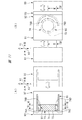
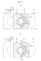
- the mold for manufacturing the first component 65 is shown in FIGS. 11 (A), 11 (B), 12 (A), 12 (B), 13 (A) and 13 (B).
- the mold 90 has cores 91, 92 and a cavity 93.
- the core 91 is movable in the left-right direction in FIG. 12 (A).
- the core 92 is movable in the vertical direction in FIG. 12 (A).
- the vertical direction in FIG. 12A corresponds to the direction along the rotation center line A1 in the first component 65 in FIG.
- the cavity 93 is movable in the left-right direction in FIG. 12 (A).
- the resin material in a fluid state is injected into the space partitioned by the cores 91, 92 and the cavity 93, and the resin material is solidified. After that, the cores 91 and 92 and the cavity 93 are separated from each other, and the first component 65 is taken out.
- the hammer drill 10 is an example of an electric working machine.
- the rotating shaft 21 is an example of a rotating element.
- the electric motor 14 is an example of an electric motor.
- the housing 11 is an example of a housing.
- the cords 52, 55, 61 are examples of electric wires.
- the bearing 22 is an example of a bearing.
- the cylinder portion 74 is an example of a holder.
- the arrangement unit 77 is an example of the arrangement unit.
- the first component 65 is an example of the first component.
- the second component 66 is an example of the second component.
- the main body 67 is an example of the first main body portion.
- the main body 70 is an example of the second main body portion.
- the tubular portion 69 is an example of the tubular portion.
- the first accommodation chamber 18 is an example of a motor accommodation chamber.
- the ribs 76A, 76B, 76C, and 76D are examples of ribs, respectively.
- Passages 84 and 85 are examples of holes.
- the passages 84 and 85 and the arrangement portion 77 are examples of the electric wire arrangement portion.
- the rotation center line A1 is an example of the rotation center line.
- the gear case 12 is an example of a case.
- the intermediate shaft 33, the cylinder 13, the gear 44, and the conversion unit 42 are examples of the operating unit.
- the handle 17 is an example of a handle.
- the trigger is an example of an operating member.
- the direction along the rotation center line A1 is an example of the axial direction of the rotation element.
- the housing is divided into the first component and the second component in the intersecting direction intersecting the axial direction of the rotating element
- the electric working machine is not limited to the hammer drill disclosed in the embodiment, and can be variously changed without departing from the gist thereof.
- the electric motor may be either a brushed motor or a brushless motor.
- the power source for supplying electric power to the electric motor may be either an AC power source or a DC power source.
- the DC power supply includes a battery pack that is attached to and detached from the handle.
- the actuating part includes at least one of a rotating element and a linearly moving element.
- the operating unit includes a piston, a cylinder, a rotating shaft, a gear, and the like.
- the operating member includes a lever, an arm, and the like.
- the operating member may be either a linearly removable member or a member that can rotate within a predetermined angle.
- the holder may be divided into a first component piece and a second component piece, the first component piece may be connected to the first component, and the second component piece may be connected to the second component.
- the electric wire arrangement portion between the first component and the first component, and at least one of the second component and the second component.
- the first rotation center line of the rotating element and the second rotation center line of the electric motor may be arranged concentrically. Further, the first rotation center line and the second center line may be arranged in parallel and eccentric to each other. Further, the first rotation center line and the second center line may be arranged so as to intersect with each other.
- the conversion unit that converts the rotational force of the electric motor into the direct power of the piston may be either a cam mechanism or a crank mechanism.
- the embodiment of the electric working machine includes a hammer driver, an impact driver, an impact wrench, a driver drill, and the like, in addition to the hammer drill.
Landscapes
- Engineering & Computer Science (AREA)
- Power Engineering (AREA)
- Mechanical Engineering (AREA)
- Connection Of Motors, Electrical Generators, Mechanical Devices, And The Like (AREA)
- Portable Power Tools In General (AREA)
- Drilling And Boring (AREA)
Abstract
ハウジングが回転要素の軸方向に大型化することを抑制可能な電動作業機を提供する。電力が供給されて回転する回転軸21を有する電動モータ14と、電動モータ14を内部に収容するハウジング11と、ハウジング11内に設けられ、かつ、電動モータ14に電力を供給するコード52,55,61と、を有する、ハンマドリル10であって、ハウジング11は、回転軸21の軸方向と交差する交差方向に分割された第1部品及び第2部品を含み、第1部品は、交差方向に向かって開口する開口部を有し、開口部に第2部品が取り付けられた状態において、交差方向における第1部品と第2部品との間に電動モータ14を収容し、第1部品と一体に形成され、電動モータ14を支持する筒部74を有し、第1部品と筒部74との間であって、開口部から見て筒部74と重なり視認不能な領域を含む電線配置部を有する。
Description
本発明は、電動モータと、電動モータが収容されたハウジングと、を有する電動作業機に関する。
電動モータと、電動モータが収容されたハウジングと、を有する電動作業機の例が、特許文献1に記載されている。特許文献1に記載された電動作業機はハンマドリルであり、ハンマドリルは、ハウジングとしてのモータハウジングと、モータハウジングに接続されたハンドルと、モータハウジング内に収容された電動モータと、を有する。電動モータは、回転要素としての出力軸を有する。モータハウジングにウェイトハウジングが取り付けられている。また、第1中間シャフト及び第2中間シャフトがウェイトハウジング内に設けられている。
ハンドルに電源ケーブルが取り付けられるとともに、トリガ及びスイッチ機構が、ハンドルに設けられている。電源ケーブルは、スイッチ機構を外部電源に接続している。作業者がトリガを操作することにより、スイッチ機構と電源とが接続及び遮断される。スイッチ機構が電源に接続されて、電動モータの出力軸が回転すると、出力軸の回転力は、第1中間シャフトを経由して第2中間シャフトに伝達される。
本願発明者は、電源の電力を電動モータに供給する電線がハウジング内に配置される位置によって、ハウジングが回転要素の軸方向に大型化する課題があることを認識した。
本発明の目的は、ハウジングが回転要素の軸方向に大型化することを抑制可能な電動作業機を提供することにある。
一実施形態の電動作業機は、電力が供給されて回転する回転要素を有する電動モータと、前記電動モータを内部に収容するハウジングと、前記ハウジング内に設けられ、かつ、前記電動モータに電力を供給する電線と、を有する、電動作業機であって、前記ハウジングは、前記回転要素の軸方向と交差する交差方向に分割された第1部品及び第2部品を含み、前記第1部品は、前記交差方向に向かって開口する開口部を有し、前記開口部に前記第2部品が取り付けられた状態において、前記交差方向における前記第1部品と前記第2部品との間に前記電動モータを収容し、前記第1部品と一体に形成され、かつ、前記電動モータを支持するホルダを有し、前記第1部品と前記ホルダとの間であって、前記開口部から見て前記ホルダと重なり視認不能な領域を含む電線配置部を有する。
本発明によれば、回転要素の軸方向で、電線の配置領域と、ホルダの配置領域とを、重ならせることが可能である。したがって、ハウジングが回転要素の軸方向に大型化することを抑制可能である。
以下、本発明の電動作業機の一実施形態であるハンマドリルを、図面を用いて説明する。
図1に示されたハンマドリル10は、ハウジング11、ギヤケース12、シリンダ13及び電動モータ14を有する。シリンダ13は、工具15を支持可能である。ハンマドリル10は、電動モータ14の動力で工具15を回転させる機能と、電動モータ14の動力で工具15に打撃力を与える機能と、を有する。
ハウジング11は、モータ収容部16及びハンドル17を有する。モータ収容部16内に第1収容室18が設けられ、電動モータ14は、第1収容室18に収容されている。電動モータ14は、モータ収容部16に固定されたステータ19と、回転可能なアーマチュア20と、を有する。アーマチュア20は導電線のコイルを有し、アーマチュア20は回転軸21に取り付けられている。回転軸21は、2個の軸受22,23によって回転中心線A1を中心として回転可能に支持されている。2個の軸受22,23は、回転軸21を、回転中心線A1を中心とする径方向、及び回転中心線A1に沿った方向に位置決めする。図1において、回転中心線A1に沿った方向は、前後方向X2と定義可能である。
ステータ19は、回転中心線A1を中心とする径方向で、アーマチュア20よりも外側に配置されている。アーマチュア20とステータ19との間に、回転軸21の径方向の隙間がある。また、回転軸21にコンミテータ24が設けられている。コンミテータ24は、交流電源48とアーマチュア20との間で電流の方向を切り替える。アーマチュア20は、電流が流れて磁界を形成する。コンミテータ24及びアーマチュア20は、回転中心線A1に沿った方向に並べて配置されている。さらに、2個の軸受22,23は、回転中心線A1に沿った方向に間隔をおいて配置されている。コンミテータ24及びアーマチュア20は、回転中心線A1に沿った方向で軸受22と軸受23との間に配置されている。コンミテータ24は、回転中心線A1に沿った方向で軸受22とアーマチュア20との間に配置されている。さらに、回転軸21は、出力ギヤ27を有している。
ハンドル17はモータ収容部16につながっている。図1では、ハンドル17が、回転中心線A1に対して交差する上下方向X3に沿って配置された例を示す。なお、上下方向X3は、回転中心線A1が、略水平であることを前提として、重力の作用方向と一致する。モータ収容部16のうち、回転中心線A1に沿った方向でハンドル17がつながった箇所とは反対の箇所に、ギヤケース12が固定されている。モータ収容部16とギヤケース12とは、固定要素、例えば、ねじ部材によって固定されている。
ギヤケース12は筒形状であり、ギヤケース12内に隔壁25が設けられている。隔壁25は、第1収容室18と、ギヤケース12の第2収容室26とを隔てる。軸受23は、隔壁25によって支持されている。回転軸21の回転中心線A1に沿った方向の端部は、第2収容室26に配置されている。出力ギヤ27は、回転軸21であって第2収容室26に配置された箇所に設けられている。
また、絶縁材料製、例えば合成樹脂製のブラシホルダ28が、ハウジング11に設けられている。ブラシホルダ28は、第1収容室18に配置されている。ブラシホルダ28は、回転軸21の径方向で回転軸21よりも外側に配置されている。ブラシホルダ28は、複数、例えば、ブラシ57,58を支持しており、ブラシ57,58はコンミテータ24の外周面にそれぞれ接触されている。ブラシ57,58は、交流電源48とコンミテータ24とを通電可能に接続する。このように、電動モータ14は、ブラシ付きモータと定義可能である。
ハンドル17において、モータ収容部16につながった箇所とは反対の箇所に電源ケーブル30が取り付けられている。電源ケーブル30は、交流電源に接続される。電源ケーブル30は、2つのコード31,32を絶縁材で被覆したものである。2つのコード31,32は、電気回路を介してブラシ57,58に接続されている。2つのコード31,32は、電流が流れる。
中間シャフト33が第2収容室26に設けられている。中間シャフト33は、回転軸21の動力を工具15に伝達する要素である。2つの軸受34,35が第2収容室26に設けられている。中間シャフト33は、2つの軸受34,35により回転中心線A2を中心として回転可能に支持されている。回転中心線A2は回転中心線A1と平行であり、かつ、回転中心線A1は回転中心線A2と非同軸に配置されている。中間シャフト33の長手方向の両端部のうち、隔壁25に近い方の端部にギヤ36が固定されている。ギヤ36は中間シャフト33と共に回転し、ギヤ36は出力ギヤ27に噛み合わされている。また、中間シャフト33にギヤ37が設けられている。
シリンダ13は、第2収容室26に設けられている。シリンダ13は、第2収容室26及びギヤケース12の外部に亘って配置されている。シリンダ13は、回転中心線A3を中心として回転可能である。回転中心線A3は、回転中心線A1,A2と平行であり、かつ、回転中心線A3は、回転中心線A1,A2に対して偏心して配置されている。
工具15は、シリンダ13に支持されている。工具15とシリンダ13とは相対回転せず、かつ、工具15は、シリンダ13に対して回転中心線A3に沿った方向の所定範囲内で移動可能である。セカンドハンマ38が、シリンダ13内で回転中心線A3に沿った方向に移動可能に設けられている。
ピストン39がシリンダ13内に配置されている。ピストン39は、シリンダに対して回転中心線A3に沿った方向に移動可能である。ピストン39は、筒形状である。ストライカ40が、ピストン39内に配置されている。ストライカ40は、ピストン39に対して回転中心線A3に沿った方向に移動可能である。ピストン39内に圧力室41が設けられている。ストライカ40は、圧力室41の圧力でセカンドハンマ38に近づく向きに付勢される。
変換部42が第2収容室26に設けられている。変換部42は、例えばカム機構を有し、変換部は、中間シャフト33の回転力をピストン39の直動力に変換する。さらに、クラッチ43が第2収容室26に設けられている。ハウジング11にモード切替レバーが設けられており、作業者がモード切替レバーを操作すると、クラッチ43が作動する。クラッチ43は、中間シャフト33と変換部42との間の動力伝達経路を接続及び遮断する。ギヤ44がシリンダ13に取り付けられており、ギヤ44がギヤ37に噛み合わされている。なお、グリップ45がギヤケース12に取り付けられており、ユーザは、手でグリップ45を握る。
トリガ46がハンドル17に設けられている。トリガ46は、ハンドル17がモータ収容部16から突出された方向でモータ収容部16に最も近い箇所に配置されている。トリガ46は、初期位置からハンドル17に対して回転中心線A1に沿った方向に作動可能である。トリガ46に対する操作力が解除されていると、トリガ46は初期位置で停止している。ユーザがトリガ46に操作力を付加すると、トリガ46は初期位置から作動する。なお、トリガ46に対する操作力が解除されると、トリガ46は、スプリングの力で初期位置へ戻って停止する。また、変速スイッチ47が、ハンドル17内に設けられている。変速スイッチ47は、トリガ46が初期位置から作動する量に応じて電動モータ14の回転速度を変更する要素である。
図4は、交流電源48から電動モータ14に電力を供給する電気回路を示している。電源ケーブル30が交流電源48に接続されると、交流電源48と変速スイッチ47とが、2本のコード31,32によって接続される。電動モータ14の回転方向を切り替える切替スイッチ49が、ハウジング11に設けられている。ステータ19は、並列に配置された導電性のコイル50,51を有する。コイル50の第1端部は、コード52によって変速スイッチ47に接続され、コイル50の第2端部は、コード53によって切替スイッチ49に接続されている。コイル51の第1端部は、コード54によって変速スイッチ47に接続され、コイル51の第2端部は、コード55によって切替スイッチ49に接続されている。さらに、コンデンサ56が、変速スイッチ47に接続されている。
ブラシ57は、コード59、チョークコイル60及びコード61を介して切替スイッチ49に接続されている。ブラシ58は、コード62、チョークコイル63及びコード64を介して切替スイッチ49に接続されている。これらのコード52,53,54,55,59,61,62,64は、第1収容室18またはハンドル17内に配置されている。コード52,53,54,55,59,61,62,64は、それぞれ電流が流れる。
ハンマドリル10の使用例を説明する。まず、ユーザは第1の手でグリップ45を握り、かつ、第2の手でハンドル17を握り、かつ、工具15を対象物に押し付ける。ユーザがトリガ46に操作力を付加すると、交流電源48から電動モータ14に電力が供給されて、ステータ19とアーマチュア20との間に磁界が発生し、回転軸21が回転する。回転軸21の回転力は、ギヤ36を経由して中間シャフト33に伝達される。中間シャフト33の回転力は、ギヤ44を経由してシリンダ13に伝達され、工具15がシリンダ13と共に回転する。
変速スイッチ47は、トリガ46が初期位置から作動する量に応じて、電動モータ14の回転軸21の回転数を調整する。トリガ46の作動量が増加すると、電動モータ14の回転軸21の回転数が上昇する。トリガ46の作動量が減少すると、電動モータ14の回転軸21の回転数が低下する。
モード切替スイッチが操作されてドリルモードが選択されていると、クラッチ43は、中間シャフト33の回転力を変換部42に伝達しない。このため、ピストン39が停止され、工具15に打撃力は付加されない。これに対して、モード切替スイッチが操作されて、ハンマドリルモードが選択されていると、クラッチ43は、中間シャフト33の回転力を変換部42に伝達する。このため、ピストン39が往復動作し、圧力室41の圧力が上昇する。したがって、ストライカ40が作動し、セカンドハンマ38が工具15を打撃する。したがって、工具15は回転され、かつ、打撃力を受ける。
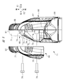
次に、ハウジング11の構成を説明する。ハウジング11は、図5のように第1部品65及び第2部品66を有する。第1部品65と第2部品66とは、物理的に別部材である。第1部品65及び第2部品66は、合成樹脂の表面を合成ゴムで被覆して、それぞれ構成されている。第1部品65と第2部品66とが、固定要素、例えば、ねじ部材78によって固定されている。
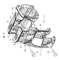
第1部品65は、本体67と、本体67につながる接続部68と、本体67につながる筒部69とを有する。本体67は、回転中心線A1に沿った方向で筒部69よりも後方側に配置される。言い換えると、筒部69は、回転中心線A1に沿った方向でギヤケース12と本体67との間に配置されている。第1部品65は、図5、図7及び図8のように、開口部72を有する。開口部72は、図5に示す本体67の左側の略全面に亘って形成され、左側に向かって開口している。第1部品65を図5のように平面視すると、開口部72は、回転中心線A1に対して交差する左右方向X1において、本体67の内部と外部とをつなげる。
ハウジング11を図5のように平面視すると、左右方向X1は、回転中心線A1に対して交差する。左右方向X1における左右は、ハウジング11を後方から見た状態で決定される。また、図5に示すハウジング11おいて、回転中心線A1に沿った方向は、前後方向X2と定義可能である。
第2部品66は、本体70と、本体70につながる接続部71と、を有する。ハウジング11を平面視すると、第1部品65の本体67及び接続部68と、第2部品66の本体70及び接続部71とが、回転中心線A1を境界として2つに分割されている。本体70は、回転中心線A1に沿った方向で本体67と同じ位置に配置されている。言い換えると、本体70は、回転中心線A1に沿った方向で筒部69の一方側に並べて配置されている。つまり、本体70は、回転中心線A1に沿った方向で筒部69の隣に配置されている。
そして、本体70が、本体67及び筒部69に接触した状態で第1部品65と第2部品66とが固定され、モータ収容部16を構成している。本体67と本体70との間、及び筒部69内に亘って第1収容室18が設けられている。また、第2部品66は、開口部72を塞ぐように第1部品65に固定されている。第2部品66の本体70は、筒部69に接触し、第2部品66の本体70と第1部品65の本体67との間に第1収容室18が設けられている。第1部品65と第2部品66とが互いに固定されると、左右方向X1において、本体67と本体70との間に電動モータ14が配置されている。さらに、接続部68と接続部71とが接触した状態で第1部品65と第2部品66とが固定され、ハンドル17を構成している。2個のブラシホルダ28は、第1部品65及び第2部品66によって挟まれて支持されている。
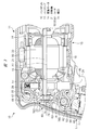
図3のように、軸受22を支持する位置決め部73が、ハウジング11に設けられている。位置決め部73は、合成樹脂製であり、位置決め部73と第1部品65とは、一体成形品である。位置決め部73は、モータ収容部16とハンドル17との接続箇所に設けられている。位置決め部73は、筒部74と、筒部74の回転中心線A1に沿った方向の端に設けた壁部75と、を有する。筒部74は、回転中心線A1の径方向で軸受22よりも外側に配置されている。回転中心線A1に沿った方向で、位置決め部73と筒部69とが、異なる位置に配置されている。
図5及び図7のように、筒部74と筒部69とをつなぐステー79が設けられている。位置決め部73は、軸受22を回転中心線A1に沿った方向に位置決めし、かつ、軸受22を回転中心線A1の径方向に位置決めする。
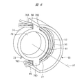
図6のように、筒部74から回転軸21の径方向に突出されたリブ76A,76B,76C,76Dが設けられている。リブ76Aとリブ76Bとは、筒部74の円周方向で同じ位置に配置され、かつ、回転中心線A1に沿った方向で異なる位置に配置されている。リブ76A,76Bは、第1部品65につながっている。
リブ76Aとリブ76Bとの間に、通路84が設けられている。通路84はリブ76A及びリブ76B、筒部74、本体67のそれぞれの壁面によって囲われている。換言すると、通路84は、第1部品65と筒部74との間に設けられた穴である。
リブ76Cとリブ76Dとは、筒部74の円周方向で同じ位置に配置され、かつ、回転中心線A1に沿った方向で異なる位置に配置されている。リブ76C,76Dは、第1部品65につながっている。リブ76Cとリブ76Dとの間に、通路85が設けられている。通路85は、リブ76C及びリブ76D、筒部74、本体67のそれぞれの壁面によって囲われている。換言すると、通路85は、第1部品65と筒部74との間に設けられた穴である。
通路84は、図6において筒部74の上に位置し、通路85は、筒部74の下に位置する。換言すると、通路84と通路85とは、回転中心線A1を中心として点対称の位置に配置されている。図8のように、第2部品66が第1部品65から離間されていると、ユーザは、開口部72を介して筒部74を視認可能である。
図3のように、軸受22は筒部74内に配置され、壁部75が軸受22を回転中心線A1に沿った方向に位置決めし、筒部74が軸受22を径方向に位置決めする。そして、図9及び図10のように、回転中心線A1を中心とする円の径方向で、筒部74の外周面と、第1部品65の内面との間に、配置部77が設けられている。配置部77は、円弧状の空間また隙間である。配置部77は、通路84,85につながっている。そして、3本のコード52,55,61の長さ方向の一部が、通路84,85及び配置部77に亘って配置されている。図5及び図8のように、第2部品66が第1部品65から離間されており、ユーザが、開口部72を見ると、ホルダ73の存在により、通路85及び配置部77を視認不可能である。
図1を参照して、ハウジング11及びギヤケース12の内部に配置されている要素の位置関係を説明する。中間シャフト33、シリンダ13、ギヤ44及び変換部42は第2収容室26に配置されている。隔壁25は、回転中心線A1に沿った方向で、第1収容室18と第2収容室26との間に配置されている。電動モータ14は、回転中心線A1に沿った方向で、隔壁25と位置決め部73との間に配置されている。
また、ハウジング11は、回転中心線A1に沿った方向でギヤケース12の反対に位置する壁80を有する。壁80は、図5及び図8に示す第1部品65の縁81と、第2部品66の縁82とが突き合わされて設けられている。さらに、位置決め部73は、回転中心線A1に沿った方向でコンミテータ24と壁80との間に配置されている。そして、配置部77は、回転中心線A1を中心とする径方向で位置決め部73よりも外側に設けられている。
そして、図6のように、3本のコード52,55,61の長さ方向の一部が、配置部77に配置されている。つまり、回転中心線A1に沿った方向で、3本のコード52,55,61の長さ方向の一部の配置領域は、位置決め部73の配置領域内にある。したがって、ハウジング11が回転中心線A1に沿った方向に大型化することを抑制できる。
さらに、ハウジング11を組み立てる場合、3本のコード52,55,61の長さ方向の一部が、リブ76Aとリブ76Bとの間、及びリブ76Cとリブ76Dとの間を通され、かつ、配置部77に配置されている状態で、第1部品65をユニット化できる。その後、第1部品65と第2部品66とを接触させ、かつ、ねじ部材78によって第1部品65と第2部品66とを固定することができる。したがって、3本のコード52,55,61の少なくとも一部が、第1部品65と第2部品66との間に挟まれることを回避できる。また、リブ76A,B,C,Dが設けられているため、位置決め部73の強度を確保できる。
第1部品65を製造する金型が、図11(A)、図11(B)、図12(A)、図12(B)、図13(A)及び図13(B)に示されている。金型90は、コア91,92及びキャビティ93を有する。コア91は、図12(A)において左右方向に移動可能である。コア92は、図12(A)において上下方向に移動可能である。図12(A)における上下方向は、図6の第1部品65における回転中心線A1に沿った方向に相当する。キャビティ93は、図12(A)において左右方向に移動可能である。
コア91,92及びキャビティ93を互いに接近させて停止させた後、コア91,92及びキャビティ93によって区画された空間へ、流動状態の樹脂材料が注入され、樹脂材料が固化する。その後、コア91,92及びキャビティ93が互いに離間され、第1部品65が取り出される。
本実施形態で開示された事項の技術的意味の一例は、次の通りである。ハンマドリル10は、電動作業機の一例である。回転軸21は、回転要素の一例である。電動モータ14は、電動モータの一例である。ハウジング11は、ハウジングの一例である。コード52,55,61は、電線の一例である。軸受22は、軸受の一例である。筒部74は、ホルダの一例である。配置部77は、配置部の一例である。第1部品65は、第1部品の一例である。第2部品66は、第2部品の一例である。本体67は、第1本体部の一例である。本体70は、第2本体部の一例である。筒部69は、筒部の一例である。第1収容室18は、モータ収容室の一例である。
リブ76A,76B,76C,76Dは、それぞれリブの一例である。通路84,85は、穴の一例である。通路84、85、配置部77は、電線配置部の一例である。回転中心線A1は、回転中心線の一例である。ギヤケース12は、ケースの一例である。中間シャフト33、シリンダ13、ギヤ44及び変換部42は、作動部の一例である。ハンドル17は、ハンドルの一例である。トリガは、操作部材の一例である。回転中心線A1に沿った方向は、回転要素の軸方向の一例である。
また、“ハウジングは、回転要素の軸方向と交差する交差方向に分割された第1部品及び第2部品”は、図5及び図10に示す左右方向X1に分割された第1部品65及び第2部品66を意味する。
電動作業機は、実施形態で開示されたハンマドリルに限定されるものではなく、その要旨を逸脱しない範囲で種々変更可能であることは言うまでもない。例えば、電動モータは、ブラシ付きモータまたはブラシレスモータの何れでもよい。電動モータに電力を供給する電源は、交流電源または直流電源の何れでもよい。直流電源は、ハンドルに着脱される電池パックを含む。作動部は、回転する要素または直動する要素のうち、少なくとも一方の要素を含む。作動部は、ピストン、シリンダ、回転軸、ギヤ等を含む。操作部材は、レバー、アーム等を含む。操作部材は、直線状に復動可能なもの、または、所定角度の範囲内で回転可能なもの、の何れでもよい。
ホルダは、第1構成片及び第2構成片に分割され、第1構成片が第1部品につながり、第2構成片が第2部品につながっていてもよい。この場合、第1部品と第1構成品との間、第2部品と第2構成品との間の少なくとも一方に、電線配置部を設けることが可能である。
回転要素の第1回転中心線と、電動モータの第2回転中心線とは、同心状に配置されていてもよい。また、第1回転中心線と第2中心線とが平行に配置され、かつ、互いに偏心して配置されていてもよい。さらに、第1回転中心線と第2中心線とが交差して配置されていてもよい。
電動モータの回転力を、ピストンの直動力に変換する変換部は、カム機構またはクランク機構の何れでもよい。電動作業機の実施形態は、ハンマドリルの他、ハンマドライバ、インパクトドライバ、インパクトレンチ、ドライバドリル、等を含む。
10…ハンマドリル、11…ハウジング、12…ギヤケース、13…シリンダ、14…電動モータ、17…ハンドル、21…回転軸、22…軸受、33…中間シャフト、42…変換部、44…ギヤ、46…トリガ、52,55,61…コード、65…第1部品、66…第2部品、67,70…本体、69,74…筒部、76A,76B,76C,76D…リブ、77…配置部、84,85…通路、A1…回転中心線
Claims (9)
- 電力が供給されて回転する回転要素を有する電動モータと、
前記電動モータを内部に収容するハウジングと、
前記ハウジング内に設けられ、かつ、前記電動モータに電力を供給する電線と、
を有する、電動作業機であって、
前記ハウジングは、前記回転要素の軸方向と交差する交差方向に分割された第1部品及び第2部品を含み、
前記第1部品は、前記交差方向に向かって開口する開口部を有し、
前記開口部に前記第2部品が取り付けられた状態において、前記交差方向における前記第1部品と前記第2部品との間に前記電動モータを収容し、
前記第1部品と一体に形成され、かつ、前記電動モータを支持するホルダを有し、
前記第1部品と前記ホルダとの間であって、前記開口部から見て前記ホルダと重なり視認不能な領域を含む電線配置部を有する、電動作業機。 - 前記電線配置部は、前記ハウジングと前記ホルダとの間に設けられて前記電線が通される穴を含む、請求項1記載の電動作業機。
- 前記ホルダと前記ハウジングとをつなぐリブが、前記回転要素の径方向に沿って延びるように設けられ、
前記穴は、前記ハウジング及び前記ホルダ、前記リブによって囲われて形成される、請求項2記載の電動作業機。 - 前記穴は、前記回転要素の回転中心線を中心として対称な2か所に形成される、請求項3記載の電動作業機。
- 前記ハウジング内に設けられ、かつ、前記回転要素を回転可能に支持する軸受を更に有し、
前記ホルダは、前記回転要素の径方向で前記軸受よりも外側に配置されて前記軸受を支持する、請求項1乃至4の何れか1項記載の電動作業機。 - 前記第1部品は、
前記回転要素の径方向で前記電動モータの外側を取り囲む筒部と、
前記回転要素の軸方向で前記筒部の一方側に配置されて前記開口部が形成される第1本体部と、
を有し、
前記第2部品は、前記軸方向で前記筒部の一方側に配置される第2本体部を有し、
前記第1本体部と前記第2本体部との間、及び前記筒部内に亘って形成され、かつ、前記電動モータを収容するモータ収容室と、
を有し、
前記ホルダは、前記第1本体部につながっており、
前記電線配置部は、前記第1本体部と前記ホルダとの間に設けられている、請求項1乃至5の何れか1項記載の電動作業機。 - 前記筒部と前記ホルダとが、前記軸方向で異なる位置に配置されている、請求項6記載の電動作業機。
- 前記ハウジングに固定されたケースと、
前記ケースによって支持され、かつ、前記回転要素から回転力が伝達されて作動する作動部と、
を有し、
前記電動モータは、前記軸方向で前記作動部と前記ホルダとの間に配置されている、請求項1乃至7の何れか1項記載の電動作業機。 - 前記ハウジングは、前記軸方向に対して交差する方向に沿って配置され、かつ、ユーザが手で握るハンドルを有し、
前記回転要素の回転数を変更するためにユーザが操作する操作部材が、前記ハンドルに設けられている、請求項1乃至8の何れか1項記載の電動作業機。
Priority Applications (4)
| Application Number | Priority Date | Filing Date | Title |
|---|---|---|---|
| JP2021554189A JP7276492B2 (ja) | 2019-10-31 | 2020-09-25 | 電動作業機 |
| US17/772,944 US20220379455A1 (en) | 2019-10-31 | 2020-09-25 | Electric power tool |
| CN202080075725.0A CN114631249B (zh) | 2019-10-31 | 2020-09-25 | 电动作业机 |
| DE112020005384.9T DE112020005384T5 (de) | 2019-10-31 | 2020-09-25 | Elektrowerkzeug |
Applications Claiming Priority (2)
| Application Number | Priority Date | Filing Date | Title |
|---|---|---|---|
| JP2019-198182 | 2019-10-31 | ||
| JP2019198182 | 2019-10-31 |
Publications (1)
| Publication Number | Publication Date |
|---|---|
| WO2021084992A1 true WO2021084992A1 (ja) | 2021-05-06 |
Family
ID=75715115
Family Applications (1)
| Application Number | Title | Priority Date | Filing Date |
|---|---|---|---|
| PCT/JP2020/036448 Ceased WO2021084992A1 (ja) | 2019-10-31 | 2020-09-25 | 電動作業機 |
Country Status (5)
| Country | Link |
|---|---|
| US (1) | US20220379455A1 (ja) |
| JP (1) | JP7276492B2 (ja) |
| CN (1) | CN114631249B (ja) |
| DE (1) | DE112020005384T5 (ja) |
| WO (1) | WO2021084992A1 (ja) |
Families Citing this family (2)
| Publication number | Priority date | Publication date | Assignee | Title |
|---|---|---|---|---|
| DE102022134555A1 (de) * | 2022-12-22 | 2024-06-27 | Andreas Stihl Ag & Co. Kg | Handgeführtes Arbeitsgerät |
| JPWO2025005244A1 (ja) * | 2023-06-30 | 2025-01-02 |
Citations (3)
| Publication number | Priority date | Publication date | Assignee | Title |
|---|---|---|---|---|
| US20090126964A1 (en) * | 2007-11-21 | 2009-05-21 | Black & Decker Inc. | Mid-handle drill construction and assembly process |
| WO2018003369A1 (ja) * | 2016-06-30 | 2018-01-04 | 日立工機株式会社 | 電動工具 |
| JP2019076994A (ja) * | 2017-10-24 | 2019-05-23 | パナソニックIpマネジメント株式会社 | 電動工具 |
Family Cites Families (18)
| Publication number | Priority date | Publication date | Assignee | Title |
|---|---|---|---|---|
| JP3676956B2 (ja) * | 1999-11-19 | 2005-07-27 | 株式会社マキタ | 電動工具及びその組み付け方法 |
| US20060028088A1 (en) * | 2004-08-06 | 2006-02-09 | Mcfarland Dalton E | Bearing support for motors |
| US8251158B2 (en) * | 2008-11-08 | 2012-08-28 | Black & Decker Inc. | Multi-speed power tool transmission with alternative ring gear configuration |
| JP5852846B2 (ja) * | 2010-12-28 | 2016-02-03 | アスモ株式会社 | モータ |
| US8901800B2 (en) * | 2010-12-28 | 2014-12-02 | Asmo Co., Ltd. | Motor |
| US8905885B2 (en) * | 2011-02-04 | 2014-12-09 | Aisin Aw Co., Ltd. | Vehicle drive device |
| JP5757172B2 (ja) * | 2011-06-16 | 2015-07-29 | 日立工機株式会社 | 電動工具 |
| JP5821620B2 (ja) * | 2011-12-26 | 2015-11-24 | アイシン・エィ・ダブリュ株式会社 | ハイブリッド駆動装置 |
| WO2014036003A1 (en) * | 2012-08-27 | 2014-03-06 | Ingersoll-Rand Company | Power tool housing construction |
| WO2015198860A1 (ja) * | 2014-06-24 | 2015-12-30 | 日立工機株式会社 | 電動作業機 |
| WO2016067997A1 (ja) * | 2014-10-29 | 2016-05-06 | 日立工機株式会社 | 動力作業機 |
| JP6453658B2 (ja) * | 2015-01-21 | 2019-01-16 | 株式会社マキタ | 電動工具 |
| EP3251803B1 (en) * | 2015-01-30 | 2022-10-26 | Koki Holdings Co., Ltd. | Work machine |
| US10876595B2 (en) * | 2016-06-17 | 2020-12-29 | Mitsuba Corporation | Speed reducer-attached motor and speed reducer-attached motor assembly method |
| JPWO2018150743A1 (ja) * | 2017-02-20 | 2019-12-12 | 日本電産株式会社 | モータ |
| JP2019131175A (ja) * | 2018-01-29 | 2019-08-08 | Ntn株式会社 | インホイールモータ駆動装置 |
| WO2019146793A1 (ja) * | 2018-01-29 | 2019-08-01 | Ntn株式会社 | インホイールモータ駆動装置 |
| DE102019107523A1 (de) * | 2018-05-24 | 2019-11-28 | Hanon Systems | Vorrichtung zum Antreiben eines Verdichters und Verfahren zum Montieren der Vorrichtung |
-
2020
- 2020-09-25 CN CN202080075725.0A patent/CN114631249B/zh active Active
- 2020-09-25 JP JP2021554189A patent/JP7276492B2/ja active Active
- 2020-09-25 WO PCT/JP2020/036448 patent/WO2021084992A1/ja not_active Ceased
- 2020-09-25 DE DE112020005384.9T patent/DE112020005384T5/de active Pending
- 2020-09-25 US US17/772,944 patent/US20220379455A1/en not_active Abandoned
Patent Citations (3)
| Publication number | Priority date | Publication date | Assignee | Title |
|---|---|---|---|---|
| US20090126964A1 (en) * | 2007-11-21 | 2009-05-21 | Black & Decker Inc. | Mid-handle drill construction and assembly process |
| WO2018003369A1 (ja) * | 2016-06-30 | 2018-01-04 | 日立工機株式会社 | 電動工具 |
| JP2019076994A (ja) * | 2017-10-24 | 2019-05-23 | パナソニックIpマネジメント株式会社 | 電動工具 |
Also Published As
| Publication number | Publication date |
|---|---|
| US20220379455A1 (en) | 2022-12-01 |
| JP7276492B2 (ja) | 2023-05-18 |
| CN114631249B (zh) | 2024-10-01 |
| DE112020005384T5 (de) | 2022-08-11 |
| CN114631249A (zh) | 2022-06-14 |
| JPWO2021084992A1 (ja) | 2021-05-06 |
Similar Documents
| Publication | Publication Date | Title |
|---|---|---|
| US20250114931A1 (en) | Impact power tool | |
| JP6574318B2 (ja) | 動力工具用のブラシレスモータ | |
| CN109909962B (zh) | 电动工具 | |
| EP2139095B1 (en) | Power tool including hybrid electric motor design | |
| CN104339324A (zh) | 冲击工具 | |
| WO2021084992A1 (ja) | 電動作業機 | |
| JP5253717B2 (ja) | Dcブラシレスモータ | |
| JP2019017129A (ja) | 電動工具 | |
| JP7684467B2 (ja) | 電動作業機 | |
| US8136559B2 (en) | Planer | |
| JP2019198158A (ja) | 電動作業機 | |
| JP5797608B2 (ja) | Dcブラシレスモータを備えた電動工具 | |
| WO2019187992A1 (ja) | 電動作業機 | |
| CN110815138B (zh) | 电动工具 | |
| JP5172034B2 (ja) | Dcブラシレスモータを備えた電動工具 | |
| CN110601488A (zh) | 一种振动电机及电动牙刷 | |
| WO2019026501A1 (ja) | 電動工具 | |
| JP2013110962A (ja) | Dcブラシレスモータを備えた電動工具 | |
| CN113459046A (zh) | 冲击工具 | |
| JP7017461B2 (ja) | 電動作業機 | |
| JP5547827B2 (ja) | Dcブラシレスモータを備えた電動工具 | |
| JP2013158133A (ja) | ステータ、電動工具用モータ、電動工具及びステータの製造方法 | |
| JP2013094063A (ja) | Dcブラシレスモータを備えた電動工具 | |
| JP7338535B2 (ja) | 作業機 | |
| JP5319028B2 (ja) | Dcブラシレスモータを備えた電動工具 |
Legal Events
| Date | Code | Title | Description |
|---|---|---|---|
| 121 | Ep: the epo has been informed by wipo that ep was designated in this application |
Ref document number: 20883627 Country of ref document: EP Kind code of ref document: A1 |
|
| ENP | Entry into the national phase |
Ref document number: 2021554189 Country of ref document: JP Kind code of ref document: A |
|
| 122 | Ep: pct application non-entry in european phase |
Ref document number: 20883627 Country of ref document: EP Kind code of ref document: A1 |